WO2017169034A1 - 船底構造及び船舶 - Google Patents
船底構造及び船舶 Download PDFInfo
- Publication number
- WO2017169034A1 WO2017169034A1 PCT/JP2017/002561 JP2017002561W WO2017169034A1 WO 2017169034 A1 WO2017169034 A1 WO 2017169034A1 JP 2017002561 W JP2017002561 W JP 2017002561W WO 2017169034 A1 WO2017169034 A1 WO 2017169034A1
- Authority
- WO
- WIPO (PCT)
- Prior art keywords
- ship
- hull
- angle
- rof
- lubrication system
- Prior art date
Links
Images


Classifications
-
- B—PERFORMING OPERATIONS; TRANSPORTING
- B63—SHIPS OR OTHER WATERBORNE VESSELS; RELATED EQUIPMENT
- B63B—SHIPS OR OTHER WATERBORNE VESSELS; EQUIPMENT FOR SHIPPING
- B63B1/00—Hydrodynamic or hydrostatic features of hulls or of hydrofoils
- B63B1/02—Hydrodynamic or hydrostatic features of hulls or of hydrofoils deriving lift mainly from water displacement
- B63B1/04—Hydrodynamic or hydrostatic features of hulls or of hydrofoils deriving lift mainly from water displacement with single hull
-
- B—PERFORMING OPERATIONS; TRANSPORTING
- B63—SHIPS OR OTHER WATERBORNE VESSELS; RELATED EQUIPMENT
- B63B—SHIPS OR OTHER WATERBORNE VESSELS; EQUIPMENT FOR SHIPPING
- B63B1/00—Hydrodynamic or hydrostatic features of hulls or of hydrofoils
- B63B1/32—Other means for varying the inherent hydrodynamic characteristics of hulls
- B63B1/34—Other means for varying the inherent hydrodynamic characteristics of hulls by reducing surface friction
- B63B1/38—Other means for varying the inherent hydrodynamic characteristics of hulls by reducing surface friction using air bubbles or air layers gas filled volumes
-
- Y—GENERAL TAGGING OF NEW TECHNOLOGICAL DEVELOPMENTS; GENERAL TAGGING OF CROSS-SECTIONAL TECHNOLOGIES SPANNING OVER SEVERAL SECTIONS OF THE IPC; TECHNICAL SUBJECTS COVERED BY FORMER USPC CROSS-REFERENCE ART COLLECTIONS [XRACs] AND DIGESTS
- Y02—TECHNOLOGIES OR APPLICATIONS FOR MITIGATION OR ADAPTATION AGAINST CLIMATE CHANGE
- Y02T—CLIMATE CHANGE MITIGATION TECHNOLOGIES RELATED TO TRANSPORTATION
- Y02T70/00—Maritime or waterways transport
- Y02T70/10—Measures concerning design or construction of watercraft hulls
Definitions
- the present invention relates to the bottom structure of a ship equipped with an air lubrication system and a ship equipped with the same.
- the air lubrication system that reduces the frictional resistance of the hull by generating bubbly flow from the bow side to the stern side during sailing and covering the bottom of the vessel with bubbly flow.
- the air lubrication system is mainly applied to ships with a fattened hull such as a tanker (expanded vessels), but application to thin-type ships such as ferries and car carriers is desired.
- ROF Rise Of Floor
- ship bottom inclined portion which inclines upward from the center toward the outside in order to maintain stability.
- the effects of the air lubrication system are fully exhibited. This is because the enlarged vessel has a flat bottom shape, so that the bubble flow is less likely to be detached from the bottom, and the effect of reducing the frictional resistance can be obtained well.
- the effect of the air lubrication system may not be sufficiently exhibited. This is because, as described above, the lean type ship is provided with the ROF to maintain the stability as described above, so there are fewer flat portions at the bottom of the ship compared to the enlarged ship, and the outer slope of the bottom is large. This is because the bubbly flow is likely to flow from the ROF to the outside and be separated from the bottom of the vessel.
- An object of the present invention is to provide a ship bottom structure and a ship capable of favorably obtaining a frictional resistance reduction effect by an air lubrication system even in a thin ship provided with a ship bottom inclined portion at the ship bottom.
- the ship bottom structure of the present invention is equipped with an air lubrication system that ejects air bubbles to the bottom of the ship, and from the center side to the outside of the ship width direction.
- the structure of the bottom of a ship having a bottom sloped portion that slopes upward, wherein the angle of the bottom sloped portion at the maximum cross-sectional position where the cross-section of the hull is maximum is greater than 0 degrees and more than 15 degrees Also, it is characterized by being set in a small range.
- the shape of the said bottom slope part in the said largest cross-sectional position is linear shape.
- the shape of the bottom slope portion at the maximum cross section position is formed in a spline curve that smoothly connects the bottom and the hull, and the angle of the bottom slope portion at the maximum cross section position is the bottom slope Specified as a tangent angle at a specific position of the part, and the specific position is a position separated by a predetermined length obtained by multiplying the width dimension of the hull by 0.4 from the center in the hull width direction Is preferred.
- the ship of the present invention is provided with an air lubrication system that ejects air bubbles to the bottom of the ship, and the ship bottom structure according to any of (1) to (3). It is characterized by
- the angle of the bottom slope portion is set in a range larger than 0 degrees and smaller than 15 degrees, separation of bubble flow from the bottom slope portion can be suppressed, and the bottom of the bottom of the bottom Even in a lean ship provided with an inclined portion, the frictional resistance reduction effect by the air lubrication system can be favorably obtained.
- FIG. 1 is a schematic side view showing the entire structure of a ship according to a first embodiment of the present invention, and a distribution map of a cross sectional area with respect to the position in the longitudinal direction of the hull is shown below.
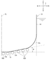
- FIG. 2 is a schematic view showing the structure (shape) of the ship bottom according to the first embodiment of the present invention, and is a cross-sectional view at the position of the maximum cross section.
- FIG. 3 is a diagram in which test results are plotted in a graph in which the horizontal axis is a flat plate inclination angle ⁇ and the vertical axis is a shear force change rate rf.
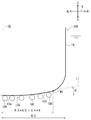
- FIG. 4 is a schematic view showing a structure (shape) of a ship bottom according to a second embodiment of the present invention, and is a cross-sectional view at the position of the maximum cross-section.
- a direction orthogonal to the longitudinal direction of the hull (hereinafter, also referred to as “longitudinal direction”) X is a hull width direction (hereinafter, also referred to as “width direction” or “ship width direction”) Y.
- the approaching side is an inner side
- the opposite side from the center line CL is an outer side.
- the bubble 100 is shown larger than the actual size.
- FIG. 1 is a schematic side view showing the entire structure of a ship according to a first embodiment of the present invention, and a distribution map of a cross sectional area with respect to the position in the longitudinal direction of the hull is shown below.
- the ship 1 includes a hull 10 which is a main body of the ship 1, a control room 20 in which various controls of the ship 1 are performed, and an air lubrication system 30.
- a propeller 16 for propelling the hull 10 is installed at the rear part (close to the stern 12), and further, a rudder 17 for determining the traveling direction of the hull 10 is installed behind the propeller 16.
- the air lubrication system 30 ejects air from the bottom 13 to generate a flow (bubble flow) of bubbles 100 at the boundary between the bottom 13 and the water surface, and the bubbles 100 form a bubble layer covering the bottom 13. Thereby, the frictional resistance of the hull 1 to be navigated can be reduced.
- the air lubrication system 30 includes, for example, an air supply source 31 configured by a blower and a compressor, a bubble ejection portion 33 installed near the bow 11 of the bottom 13, the air supply source 31 and the bubble ejection portion 33. And the air supply passage 32 connecting them, and by operating the air supply source 31, the air bubbles 100 are ejected from the air bubble ejection part 33 toward the stern 12.
- the horizontal axis is "position P with respect to the longitudinal direction X of the hull” and the vertical axis is "cross sectional area of the hull 10 (area of cross section cut perpendicular to the longitudinal direction X of the hull)"
- the cross-sectional distribution diagram in which the distribution of the cross-sectional area of the hull 10 is plotted is shown in the graph of FIG.
- the position of the horizontal axis corresponds to the position of the hull 10 shown in the upper side view.
- the cross-sectional area A of the hull 10 is usually largest at the central portion in the front-rear direction X.
- the maximum cross sectional position Pmax the position in the front-rear direction X at which the cross sectional area A becomes maximum
- the maximum cross sectional position Pmax the maximum cross sectional area
- the maximum cross sectional area Amax is referred to as the maximum cross sectional area Amax.
- FIG. 2 is a schematic cross-sectional view showing the structure (shape) of the bottom 13 and is a cross-sectional view at the maximum cross-sectional position Pmax (see FIG. 1).
- FIG. 2 shows only the right side, ie, the side of the starboard (ship) 14 with respect to the center line CL in the width direction Y
- the shape of the hull 10 is symmetrical with respect to the center line CL
- the shape of the bottom 13 is also
- the shape on the starboard 14 side and the shape on the port side are axisymmetrical. Therefore, only the starboard side (one side) is shown in FIG.
- the bottom 13 includes a central horizontal flat keel portion 13a, the ROF 13b continuously provided outside the keel portion 13a, and a curved portion 13c that smoothly connects the ROF 13b and the starboard 14.
- the ROF 13 b has a linear shape that linearly connects the outer end of the keel portion 13 a and the inner end of the curved portion 13 c in the cross section at the maximum cross section position Pmax.
- the inclination angle (hereinafter also referred to as "ROF angle") ⁇ of the ROF 13b is defined as the angle of the ROF with respect to the keel portion 13a which is in the horizontal posture in the stable state at the time of navigation. If the ROF angle ⁇ at the maximum cross sectional position Pmax is smaller than 15 degrees ( ⁇ ⁇ 15), the peeling of the air bubble 100 is suppressed, and a layer of air bubble 100 is formed in the ROF 13b as shown in FIG. Is known from the test results.
- FIG. 3 is a diagram in which the test result is plotted in a graph in which the horizontal axis represents the flat plate inclination angle ⁇ and the vertical axis represents the shear force change rate rf.
- a flat plate is submerged in a flow of water, and a shear force change rate rf of a tilt angle (flat plate tilt angle) ⁇ of the flat plate is measured.
- the flat plate inclination angle ⁇ is an angle based on the horizontal, and corresponds to the ROF angle ⁇ .
- the shear force change rate rf is lower than 1, it can be determined that air bubbles capable of reducing the friction acting on the flat plate as a shear force are attached to the flat plate, and the shear force change rate rf is low. It can be determined that there were a lot of bubbles adhering to the flat plate.
- the ROF angle ⁇ at the maximum cross sectional position Pmax is generally defined by the shape of the hull forward of the maximum cross sectional position Pmax or in order to suppress the resistance that the hull receives during navigation. Since the ROF angle ⁇ increases toward the rear side, the upper limit of the ROF angle ⁇ is defined at the maximum cross sectional position Pmax that has little influence on the resistance during navigation even when flattened. Also, as shown in the distribution map of the cross sectional area of the hull in FIG.
- the shear force change rate rf can be made smaller as the flat plate inclination angle ⁇ is made smaller, so it is preferable to make the ROF angle ⁇ smaller as well.
- the ROF 13 b itself disappears, so the ROF angle ⁇ is naturally larger than 0 [degree] ( ⁇ > 0).
- the ROF angle ⁇ is set to a range larger than 0 [degree] and smaller than 15 [degree], suppressing separation of the air bubble 100 from the ROF 13 b Even in the case of a thin ship provided with the ROF 13b at the bottom 13, the reduction effect of the frictional resistance by the air lubrication system 30 can be favorably obtained.
- FIG. 4 is a schematic cross-sectional view showing the structure (shape) of the bottom of the second embodiment of the present invention, and is a cross-sectional view at the maximum cross-sectional position Pmax (see FIG. 1).
- the same components as those of the first embodiment are denoted by the same reference numerals, and the description thereof is omitted.
- the ship of this embodiment is different from the first embodiment in the configuration of the ROF. Specifically, as shown in FIG.
- the bottom 13A of the hull 10A of the present embodiment includes a central horizontal flat keel portion 13a and an ROF 13b 'continuously provided outside the keel portion 13a.
- the ROF 13 b ′ is formed into a curved shape (spline curve shape) that smoothly connects with the starboard 14.
- the inclination angle (also referred to as "ROF angle”) ⁇ 'of the curved ROF 13b' is defined as the angle of the tangent L1 at the specific position W1 with respect to the keel portion 13a.
- width dimension the dimension in the width direction Y of the hull 10A
- width dimension of the right half of the hull 10A is (B / 2)
- W1 is 0.8 ⁇ (B / 2) This means a position separated in the width direction Y from the center line CL by 0.4 ⁇ B.
- the ROF angle ⁇ ′ is a representative inclination angle of the curved ROF 13b ′, and the ROF angle ⁇ ′ is in a range larger than 0 [degree] and smaller than 15 [degree] as in the first embodiment (0 ⁇ ′ By setting to ⁇ 15), peeling of the air bubble 100 can be suppressed.
- the ROF angle ⁇ ′ is set in a range larger than 0 [degree] and smaller than 15 [degree]. Peeling off of the air bubbles 100 can be suppressed, and the frictional resistance reduction effect by the air lubrication system can be favorably obtained even in a thin boat provided with the ROF 13b 'at the bottom 13A.
Landscapes
- Physics & Mathematics (AREA)
- Fluid Mechanics (AREA)
- Chemical & Material Sciences (AREA)
- Engineering & Computer Science (AREA)
- Combustion & Propulsion (AREA)
- Mechanical Engineering (AREA)
- Ocean & Marine Engineering (AREA)
- Vibration Prevention Devices (AREA)
- Lubricants (AREA)
Abstract
Description
空気潤滑システムは、主に、タンカーのような船体が肥えた船(肥大船)について適用されているが、フェリーや自動車運搬船のような痩せ型船についても適用が望まれている。
痩せ型船は、復原性の保持するために、船底に、中央から外側に向かって上方へ傾斜する傾斜部(ROF:Rise Of Floor。以下、ROF又は船底傾斜部ともいう)が設けられている(例えば特許文献1参照)。
その一方、空気潤滑システムを痩せ型船に適用しようとすると、空気潤滑システムの効果が十分に発揮されないおそれがある。これは、痩せ型船は、上述したとおり復原性の保持するためにROFが設けられているので、肥大船に較べて、船底部分にフラットな部分が少なく、船底部分の外側の傾斜が大きいため、気泡流がROFから外側へと流れて船底から剥離しやすいためである。
なお、以下の説明では、船舶1の船首11側(進行方向)を前方とし、船尾12側を後方とし、前方を基準に左右を定め、重力の方向を下方とし、その逆を上方として説明する。また、船体前後方向(以下「前後方向」ともいう)Xと直交する方向を船体幅方向(以下「幅方向」又は「船幅方向」ともいう)Yとし、船幅方向Yの中心線CLに近づく側を内側とし、その逆に中心線CLから離れる側を外側として説明する。また、便宜上、図2、4では気泡100を実際よりも大きく示す。
各実施形態では、本発明をフェリーに使用される痩せ型船に適用した例を説明する。
[1-1.構成]
本発明の第1実施形態としての船舶の全体構成について、図1を参照して説明する。
図1は、本発明の第1実施形態としての船舶の全体構成を示す模式な側面図であり、その下方に船体前後方向の位置に関する横断面積の分布図を併せて示す。
船舶1は、船舶1の本体である船体10と、船舶1の各種制御が行われるコントロールルーム20と、空気潤滑システム30とを備える。
空気潤滑システム30は、船底13から空気を噴出して船底13と水面との境界に気泡100の流れ(気泡流)を発生させ、この気泡100により船底13を覆う気泡層を形成する。これにより、航行する船体1の摩擦抵抗を低減することができる。
具体的には、空気潤滑システム30は、例えばブロアやコンプレッサにより構成される空気供給源31と、船底13の船首11寄りに設置された気泡噴出部33と、空気供給源31と気泡噴出部33とを繋ぐ空気供給通路32とを備えて構成され、空気供給源31を作動させることで、気泡噴出部33から船尾12に向けて気泡100が噴出される。
この分布図でもそうであるが、通常、船体10の横断面積Aは、前後方向Xの中央部で最大となる。以下、横断面積Aが最大となる前後方向Xの位置を最大横断面位置Pmaxと呼び、最大の横断面積を最大横断面積Amaxと呼ぶ。
図2は、船底13の構造(形状)を示す模式的な横断面図であって、最大横断面位置Pmax(図1参照)における横断面図である。
図2では、船幅方向Yの中心線CLよりも右側つまり右舷(船舷)14側のみ示すが、船体10の形状は中心線CLに対して対称の形状となっており、船底13の形状も、右舷14側の形状と左舷側の形状とは線対称の形状となっている。そこで、図2では右舷14側(片側)だけを示し、右舷14側の形状を代表として船底13の形状について説明する。
船体10には、船舶1が痩せ型船であることから、復原性を保持するために、船底13に中央から外側に向かって上方へ傾斜する傾斜部(ROF:Rise Of Floor。以下、ROF又は船底傾斜部ともいう)13bが設けられている。
船底13は、中央の水平且つ平坦なキール部13aと、キール部13aの外側に連設される前記ROF13bと、ROF13bと右舷14とを滑らかに繋ぐ湾曲部13cとを備えて構成されている。
この最大横断面位置PmaxにおけるROF角度φが15[degree]よりも小さいと(φ<15)、気泡100の剥離が抑制され、図2に示すようにROF13bに気泡100の層が形成されることが試験結果から判明している。
図3は、横軸を平板傾斜角度θとし、縦軸をせん断力変化率rfとしたグラフに試験結果をプロットした図である。
この試験は、水の流れの中に平板を水没させ、この平板の傾斜角度(平板傾斜角度)θのせん断力変化率rfを計測したものである。平板傾斜角度θは水平を基準とした角度であり、ROF角度φに相当する。
また、せん断力変化率rfとは、「空気潤滑システムの非作動時に平板が前記の水の流れから受けるせん断力f_off」に対する「空気潤滑システムの作動時に平板が前記の水の流れから受けるせん断力f_on」の比である(rf=f_on/f_off)である。したがって、せん断力変化率rfが1よりも低ければ、空気潤滑システムの効果が得られ、また、せん断力変化率rfが低いほど空気潤滑システムの効果が高かったと判定できる。換言すれば、せん断力変化率rfが1よりも低ければ、せん断力として平板に作用する摩擦を低減できる量の気泡が、平板に付着していたと判定でき、また、せん断力変化率rfが低いほど平板に付着していた気泡が多かったと判定できる。
本発明の第1実施形態によれば、ROF角度φが、0[degree]よりも大きく15[degree]よりも小さい範囲に設定されているので、ROF13bからの気泡100の剥離を抑制することができ、船底13にROF13bを備えた痩せ型船においても空気潤滑システム30による摩擦抵抗の低減効果を良好に得ることができる。
[2-1.構成]
本発明の第2実施形態の船舶について、図4を参照して説明する。
図4は、本発明の第2実施形態の船底の構造(形状)を示す模式的な横断面図であって、最大横断面位置Pmax(図1参照)における横断面図である。なお、第1実施形態と同一の構成要素については同一の符号を付し、その説明を省略する。
本実施形態の船舶は、第1実施形態に対しROFの構成が異なる。具体的には、図4に示すように、本実施形態の船体10Aの船底13Aは、中央の水平且つ平坦なキール部13aと、キール部13aの外側に連設されるROF13b′とを備えて構成され、ROF13b′は、右舷14とを滑らかに繋ぐ湾曲形状(スプラインカーブ状)とされている。
特定位置W1は、船体10Aの幅方向Yの寸法(以下「幅寸法」という)をBとし、船体10Aの右舷半分の幅寸法を(B/2)としたときに、0.8×(B/2)すなわち0.4×Bだけ、中心線CLから幅方向Yに離れた位置をいう。
ROF角度φ′は、湾曲形状のROF13b′の代表傾斜角度であり、ROF角度φ′を、第1実施形態と同様に0[degree]より大きく15[degree]よりも小さい範囲(0<φ′<15)に設定することにより気泡100の剥離を抑制できる。
本発明の第2実施形態によれば、第1実施形態と同様に、ROF角度φ′が、0[degree]よりも大きく15[degree]よりも小さい範囲で設定されているので、ROF13b′からの気泡100の剥離を抑制することができ、船底13AにROF13b′を備えた痩せ型船においても空気潤滑システムによる摩擦抵抗低減効果を良好に得ることができる。
上記各実施形態では、本発明をフェリーに適用した例を説明したが、本発明はROFを有する痩せ型船であればフェリーに限定されることなく適用しうるものであり、例えば自動車運搬船にも適用できる。
10,10A 船体
13 船底
13a キール部
13b,13b′ 船底傾斜部,ROF
14 右舷(船舷)
CL 船幅方向Yの中心線
30 空気潤滑システム
33 気泡噴出部
W1 船底傾斜部13b′の特定位置
L1 特定位置Wにおける接線
CL 船幅方向Yの中心線
φ 船底傾斜部13bの傾斜角度(ROF角度)
φ′ 船底傾斜部13b′の傾斜角度(ROF角度)
Claims (4)
- 船体の船底に気泡を噴出する空気潤滑システムを装備すると共に、前記船底に、船体幅方向の中心側から外側に向かって上方に傾斜する船底傾斜部を備えた船舶の前記船底の構造であって、
前記船体の横断面が最大となる最大横断面位置における前記船底傾斜部の角度が、0度よりも大きく15度よりも小さい範囲で設定されたことを特徴とする、船底構造。 - 前記最大横断面位置における前記船底傾斜部の形状が、直線形状であることを特徴とする、請求項1に記載の船底構造。
- 前記最大横断面位置における前記船底傾斜部の形状が、前記船底と船舷とを滑らかに繋ぐスプラインカーブ状に形成され、
前記最大横断面位置における前記船底傾斜部の角度が、前記船底傾斜部の特定位置における接線の角度として規定され、
前記特定位置は、前記船体幅方向の中心から、前記船体の幅寸法に0.4を乗じて得られた所定長さだけ離れた位置である
ことを特徴とする、請求項1に記載の船底構造。 - 船体の船底に気泡を噴出する空気潤滑システムと、
請求項1~3の何れか一項に記載の船底構造とを備えた
ことを特徴とする、船舶。
Priority Applications (1)
| Application Number | Priority Date | Filing Date | Title |
|---|---|---|---|
| KR1020187020106A KR102114753B1 (ko) | 2016-03-31 | 2017-01-25 | 선저 구조 및 선박 |
Applications Claiming Priority (2)
| Application Number | Priority Date | Filing Date | Title |
|---|---|---|---|
| JP2016-071337 | 2016-03-31 | ||
| JP2016071337A JP6674821B2 (ja) | 2016-03-31 | 2016-03-31 | 船底構造及び船舶 |
Publications (1)
| Publication Number | Publication Date |
|---|---|
| WO2017169034A1 true WO2017169034A1 (ja) | 2017-10-05 |
Family
ID=59962820
Family Applications (1)
| Application Number | Title | Priority Date | Filing Date |
|---|---|---|---|
| PCT/JP2017/002561 WO2017169034A1 (ja) | 2016-03-31 | 2017-01-25 | 船底構造及び船舶 |
Country Status (3)
| Country | Link |
|---|---|
| JP (1) | JP6674821B2 (ja) |
| KR (1) | KR102114753B1 (ja) |
| WO (1) | WO2017169034A1 (ja) |
Citations (2)
| Publication number | Priority date | Publication date | Assignee | Title |
|---|---|---|---|---|
| JP2003104279A (ja) * | 2001-10-01 | 2003-04-09 | Shipbuilding Research Centre Of Japan | 大型輸送船 |
| JP2014012443A (ja) * | 2012-07-04 | 2014-01-23 | Japan Marine United Corp | 摩擦抵抗低減船 |
Family Cites Families (4)
| Publication number | Priority date | Publication date | Assignee | Title |
|---|---|---|---|---|
| JP5059725B2 (ja) | 2008-09-24 | 2012-10-31 | 株式会社新来島どっく | 自動車運搬船 |
| KR20100049150A (ko) * | 2008-11-03 | 2010-05-12 | 현대중공업 주식회사 | 발라스트수의 사용을 감소시킨 대형 운반선 |
| KR102122091B1 (ko) * | 2013-09-27 | 2020-06-11 | 대우조선해양 주식회사 | 아령형 구상선수 구조 및 그 구조를 포함하는 선박 |
| JP6354082B2 (ja) * | 2015-01-13 | 2018-07-11 | 三菱造船株式会社 | 船舶 |
-
2016
- 2016-03-31 JP JP2016071337A patent/JP6674821B2/ja active Active
-
2017
- 2017-01-25 WO PCT/JP2017/002561 patent/WO2017169034A1/ja active Application Filing
- 2017-01-25 KR KR1020187020106A patent/KR102114753B1/ko active IP Right Grant
Patent Citations (2)
| Publication number | Priority date | Publication date | Assignee | Title |
|---|---|---|---|---|
| JP2003104279A (ja) * | 2001-10-01 | 2003-04-09 | Shipbuilding Research Centre Of Japan | 大型輸送船 |
| JP2014012443A (ja) * | 2012-07-04 | 2014-01-23 | Japan Marine United Corp | 摩擦抵抗低減船 |
Also Published As
| Publication number | Publication date |
|---|---|
| JP2017178182A (ja) | 2017-10-05 |
| JP6674821B2 (ja) | 2020-04-01 |
| KR20180091917A (ko) | 2018-08-16 |
| KR102114753B1 (ko) | 2020-05-26 |
Similar Documents
| Publication | Publication Date | Title |
|---|---|---|
| US8047148B2 (en) | Ship | |
| US7578250B2 (en) | Watercraft with wave deflecting hull | |
| US9517813B2 (en) | Hybrid monohull planing vessels | |
| US20050215132A1 (en) | Line design and propulsion system for a directionally stable, seagoing boat with rudder propeller drive system | |
| JP2008260445A (ja) | 船舶 | |
| JP6687673B2 (ja) | 風圧抵抗の少ない船舶 | |
| US10953955B1 (en) | Pontoon-style vessel having motor pod providing extreme turning radius and performance handling | |
| US20160207591A1 (en) | Variable Second Pad Keel | |
| US20150329178A1 (en) | Planing Hull with Concentric Pad Keel | |
| US8915206B1 (en) | T-step hull form for monohull planing vessels | |
| US10106234B2 (en) | High speed triangular shaped hydroplaning monohull craft with aircraft-like control surfaces having surface adhesion hull characteristics | |
| JP2015085930A (ja) | 水上走行体 | |
| US10858069B2 (en) | Marine vessel hull with a longitudinally vented transverse step | |
| WO2017169034A1 (ja) | 船底構造及び船舶 | |
| KR20140078272A (ko) | 선박 | |
| US7165503B2 (en) | Hull of a ship having a central keel and side chines | |
| US8281730B2 (en) | Watercraft with asymmetrical and symmetrical boat hull | |
| TWI821906B (zh) | 包含滑行船體之船舶及操作船舶之方法 | |
| KR101810696B1 (ko) | 선박 | |
| US11319025B2 (en) | Marine vessel hull with a longitudinally-vented, partial-beam transverse step | |
| US20200331561A1 (en) | Marine vessel hull with a longitudinally-vented, partial-beam transverse step | |
| JP2002145171A (ja) | 摩擦抵抗低減型船舶 | |
| US10676158B2 (en) | Watercraft using narrowing concave channels | |
| CN114829243A (zh) | 水运工具 | |
| JP2011093366A (ja) | 船体形状 |
Legal Events
| Date | Code | Title | Description |
|---|---|---|---|
| ENP | Entry into the national phase |
Ref document number: 20187020106 Country of ref document: KR Kind code of ref document: A |
|
| WWE | Wipo information: entry into national phase |
Ref document number: 1020187020106 Country of ref document: KR |
|
| NENP | Non-entry into the national phase |
Ref country code: DE |
|
| 121 | Ep: the epo has been informed by wipo that ep was designated in this application |
Ref document number: 17773584 Country of ref document: EP Kind code of ref document: A1 |
|
| 122 | Ep: pct application non-entry in european phase |
Ref document number: 17773584 Country of ref document: EP Kind code of ref document: A1 |