WO2017168971A1 - 回転電機の固定子及びそれを用いた回転電機 - Google Patents
回転電機の固定子及びそれを用いた回転電機 Download PDFInfo
- Publication number
- WO2017168971A1 WO2017168971A1 PCT/JP2017/001624 JP2017001624W WO2017168971A1 WO 2017168971 A1 WO2017168971 A1 WO 2017168971A1 JP 2017001624 W JP2017001624 W JP 2017001624W WO 2017168971 A1 WO2017168971 A1 WO 2017168971A1
- Authority
- WO
- WIPO (PCT)
- Prior art keywords
- stator
- connection
- phase
- layer
- electrical machine
- Prior art date
- Legal status (The legal status is an assumption and is not a legal conclusion. Google has not performed a legal analysis and makes no representation as to the accuracy of the status listed.)
- Ceased
Links
Images






Classifications
-
- H—ELECTRICITY
- H02—GENERATION; CONVERSION OR DISTRIBUTION OF ELECTRIC POWER
- H02K—DYNAMO-ELECTRIC MACHINES
- H02K3/00—Details of windings
- H02K3/04—Windings characterised by the conductor shape, form or construction, e.g. with bar conductors
- H02K3/28—Layout of windings or of connections between windings
-
- H—ELECTRICITY
- H02—GENERATION; CONVERSION OR DISTRIBUTION OF ELECTRIC POWER
- H02K—DYNAMO-ELECTRIC MACHINES
- H02K3/00—Details of windings
- H02K3/04—Windings characterised by the conductor shape, form or construction, e.g. with bar conductors
- H02K3/12—Windings characterised by the conductor shape, form or construction, e.g. with bar conductors arranged in slots
-
- H—ELECTRICITY
- H02—GENERATION; CONVERSION OR DISTRIBUTION OF ELECTRIC POWER
- H02K—DYNAMO-ELECTRIC MACHINES
- H02K3/00—Details of windings
- H02K3/32—Windings characterised by the shape, form or construction of the insulation
- H02K3/38—Windings characterised by the shape, form or construction of the insulation around winding heads, equalising connectors, or connections thereto
-
- H—ELECTRICITY
- H02—GENERATION; CONVERSION OR DISTRIBUTION OF ELECTRIC POWER
- H02K—DYNAMO-ELECTRIC MACHINES
- H02K3/00—Details of windings
- H02K3/46—Fastening of windings on the stator or rotor structure
- H02K3/50—Fastening of winding heads, equalising connectors, or connections thereto
-
- H—ELECTRICITY
- H02—GENERATION; CONVERSION OR DISTRIBUTION OF ELECTRIC POWER
- H02P—CONTROL OR REGULATION OF ELECTRIC MOTORS, ELECTRIC GENERATORS OR DYNAMO-ELECTRIC CONVERTERS; CONTROLLING TRANSFORMERS, REACTORS OR CHOKE COILS
- H02P27/00—Arrangements or methods for the control of AC motors characterised by the kind of supply voltage
- H02P27/04—Arrangements or methods for the control of AC motors characterised by the kind of supply voltage using variable-frequency supply voltage, e.g. inverter or converter supply voltage
- H02P27/06—Arrangements or methods for the control of AC motors characterised by the kind of supply voltage using variable-frequency supply voltage, e.g. inverter or converter supply voltage using DC to AC converters or inverters
-
- H—ELECTRICITY
- H02—GENERATION; CONVERSION OR DISTRIBUTION OF ELECTRIC POWER
- H02P—CONTROL OR REGULATION OF ELECTRIC MOTORS, ELECTRIC GENERATORS OR DYNAMO-ELECTRIC CONVERTERS; CONTROLLING TRANSFORMERS, REACTORS OR CHOKE COILS
- H02P9/00—Arrangements for controlling electric generators for the purpose of obtaining a desired output
- H02P9/14—Arrangements for controlling electric generators for the purpose of obtaining a desired output by variation of field
- H02P9/26—Arrangements for controlling electric generators for the purpose of obtaining a desired output by variation of field using discharge tubes or semiconductor devices
- H02P9/30—Arrangements for controlling electric generators for the purpose of obtaining a desired output by variation of field using discharge tubes or semiconductor devices using semiconductor devices
-
- H—ELECTRICITY
- H02—GENERATION; CONVERSION OR DISTRIBUTION OF ELECTRIC POWER
- H02K—DYNAMO-ELECTRIC MACHINES
- H02K17/00—Asynchronous induction motors; Asynchronous induction generators
- H02K17/02—Asynchronous induction motors
- H02K17/12—Asynchronous induction motors for multi-phase current
-
- H—ELECTRICITY
- H02—GENERATION; CONVERSION OR DISTRIBUTION OF ELECTRIC POWER
- H02K—DYNAMO-ELECTRIC MACHINES
- H02K47/00—Dynamo-electric converters
- H02K47/18—AC/AC converters
- H02K47/30—Single-armature phase-number converters without frequency conversion
Definitions
- the present invention relates to a rotating electric machine such as a motor or a generator, and a stator of the rotating electric machine.
- Patent Document 1 describes a structure of a rotating electrical machine in which a three-phase wire is disposed at a non-connection side coil end.
- the stator of the rotating electrical machine shown in FIG. 2 has a configuration in which a three-phase output line connected from the non-connection side coil end to the current sensor is arranged.
- a three-phase output line connected from the non-connection side coil end to the current sensor is arranged.
- this requires a significant change in the structure, which complicates the stator assembly process. Become.
- an object of the present invention is to provide a rotating electrical machine that can simplify the process while adopting a configuration in which a three-phase output line is provided from the connection side coil end.
- connection-side winding portion disposed on one side of the stator core and connected to the slot at the same slot pitch
- stator core A plurality of segment coils having a plurality of segment coils disposed on the other side of the slot and inserted at a plurality of types of slot pitches with respect to the slots.
- a first connection group provided with a plurality of terminal portions for connecting the first connection group, and a second connection group for connecting a different layer from the first connection group and provided with a plurality of terminal portions.
- a plurality of slot pitches are required for either the connection side coil end or the anti-connection side coil end, but the slot pitch of the anti-connection side coil end is a plurality of arrangements as in this embodiment.
- the slot pitch of the connection side coil end can be made the same, and the twist forming process can be performed at one time, thereby simplifying the process.
- FIG. 4 is an r- ⁇ cross-sectional view of the stator 230 and the rotor 250 of the present embodiment.
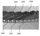
- FIG. 13B is an enlarged view of part B in FIG. 13A, and shows a 5-slot pitch segment coil 248 and a 7-slot pitch segment coil 249 provided for each winding group shown in the connection diagram of FIG. 11. It is an enlarged view of.
- the rotating electrical machine according to the present invention can be applied to a pure electric vehicle that runs only by the rotating electrical machine and a hybrid type electric vehicle that is driven by both the engine and the rotating electrical machine.
- a hybrid type electric vehicle is taken as an example. explain.
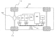
- FIG. 1 is a diagram showing a schematic configuration of a hybrid electric vehicle equipped with a rotating electrical machine according to an embodiment of the present invention.
- the vehicle 100 is mounted with an engine 120, a first rotating electrical machine 200, a second rotating electrical machine 202, and a battery 180.
- the battery 180 supplies DC power to the first rotating electric machine 200 and the second rotating electric machine 202 via the power converter 600 when the driving force by the first rotating electric machine 200 and the second rotating electric machine 202 is required. Supply. Further, the battery 180 receives DC power from the first rotating electric machine 200 and the second rotating electric machine 202 during regenerative running. Transfer of DC power between the battery 180 and the first rotating electrical machine 200 or the second rotating electrical machine 202 is performed via the power converter 600.
- the vehicle is equipped with a battery that supplies low-voltage power (for example, 14 volt system power) and supplies DC power to a control circuit described below.
- Rotational torque by the engine 120 and the first rotating electric machine 200 and the second rotating electric machine 202 is transmitted to the front wheels 110 via the transmission 130 and the differential gear 160.
- the transmission 130 is controlled by a transmission control device 134
- the engine 120 is controlled by an engine control device 124.
- the battery 180 is controlled by the battery control device 184.
- Transmission control device 134, engine control device 124, battery control device 184, power conversion device 600 and integrated control device 170 are connected by communication line 174.
- the integrated control device 170 is a higher-level control device than the transmission control device 134, the engine control device 124, the power conversion device 600, and the battery control device 184, and the transmission control device 134, the engine control device 124, and the power conversion device 600. And information representing each state of the battery control device 184 is received from each of them via the communication line 174. The integrated control device 170 calculates a control command for each control device based on the acquired information. The calculated control command is transmitted to each control device via the communication line 174.
- the high voltage battery 180 is composed of a secondary battery such as a lithium ion battery or a nickel metal hydride battery, and outputs a high voltage DC power of 250 to 600 volts or more.
- the battery control device 184 outputs the charge / discharge status of the battery 180 and the state of each unit cell battery constituting the battery 180 to the integrated control device 170 via the communication line 174.
- the integrated control device 170 determines that the battery 180 needs to be charged based on the information from the battery control device 184, the integrated control device 170 instructs the power conversion device 600 to perform a power generation operation.
- the integrated control device 170 mainly manages the output torque of the engine 120, the first rotating electrical machine 200, and the second rotating electrical machine 202, the output torque of the engine 120, the first rotating electrical machine 200, and the second rotation. Computation processing of the total torque and torque distribution ratio with the output torque of the electric machine 202 is performed, and a control command based on the computation processing result is transmitted to the transmission control device 134, the engine control device 124 and the power conversion device 600. Based on the torque command from the integrated control device 170, the power conversion device 600 controls the first rotating electrical machine 200 and the second rotating electrical machine 202 so as to generate torque output or generated power as commanded.
- Power converter 600 is provided with a power semiconductor that constitutes an inverter circuit for operating first rotating electric machine 200 and second rotating electric machine 202.
- the power conversion device 600 controls the switching operation of the power semiconductor based on a command from the integrated control device 170. By the switching operation of the power semiconductor, the first rotating electric machine 200 and the second rotating electric machine 202 are operated as an electric motor or a generator.
- DC power from the high-voltage battery 180 is supplied to the DC terminal of the inverter of the power converter 600.
- the power converter 600 converts the DC power supplied by controlling the switching operation of the power semiconductor into three-phase AC power, and supplies it to the first rotating electric machine 200 and the second rotating electric machine 202.
- the first rotating electrical machine 200 and the second rotating electrical machine 202 are operated as generators, the rotors of the first rotating electrical machine 200 and the second rotating electrical machine 202 rotate with rotational torque applied from the outside.
- three-phase AC power is generated in the stator windings of the first rotating electric machine 200 and the second rotating electric machine 202.
- the generated three-phase AC power is converted into DC power by the power converter 600, and the DC power is supplied to the high-voltage battery 180, whereby the battery 180 is charged.
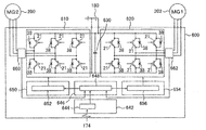
- FIG. 2 shows a circuit diagram of the power conversion device 600 of FIG.
- the power conversion device 600 is provided with a first inverter device for the rotating electrical machine 200 and a second inverter device for the rotating electrical machine 202.
- the first inverter device includes a power module 610, a first drive circuit 652 that controls the switching operation of each power semiconductor 21 of the power module 610, and a current sensor 660 that detects the current of the first rotating electrical machine 200. I have.
- the first drive circuit 652 is provided on the drive circuit board 650.
- the second inverter device includes a power module 620, a second drive circuit 656 that controls the switching operation of each power semiconductor 21 in the power module 620, and a current sensor 662 that detects the current of the second rotating electrical machine 202.
- the second drive circuit 656 is provided on the drive circuit board 654.
- the control circuit 648 provided on the control circuit board 646, the capacitor module 630, and the transmission / reception circuit 644 mounted on the connector board 642 are commonly used by the first inverter device and the second inverter device.
- the power module 610 and the power module 620 operate according to the drive signals output from the corresponding first drive circuit 652 and second drive circuit 656, respectively.
- the power module 610 and the power module 620 convert DC power supplied from the battery 180 into three-phase AC power, respectively, and the armature windings of the first rotating electrical machine 200 and the second rotating electrical machine 202 corresponding to the power. Is supplied to the stator winding.
- the power modules 610 and 620 convert AC power induced in the stator windings of the first rotating electric machine 200 and the second rotating electric machine 202 into DC and supply it to the battery 180.
- the power module 610 and the power module 620 include a three-phase bridge circuit as shown in FIG. 2, and series circuits corresponding to the three phases are electrically connected in parallel between the positive electrode side and the negative electrode side of the battery 180, respectively. It is connected.
- Each series circuit includes a power semiconductor 21 constituting an upper arm and a power semiconductor 21 constituting a lower arm, and these power semiconductors 21 are connected in series.
- the power module 610 and the power module 620 have substantially the same circuit configuration as shown in FIG. 2, and the power module 610 will be described as a representative here.
- an IGBT (insulated gate bipolar transistor) 21 is used as a switching power semiconductor element.
- the IGBT 21 includes three electrodes, a collector electrode, an emitter electrode, and a gate electrode.
- a diode 38 is electrically connected between the collector electrode and the emitter electrode of the IGBT 21.
- the diode 38 includes two electrodes, a cathode electrode and an anode electrode.
- the cathode electrode is the collector electrode of the IGBT 21 and the anode electrode is the IGBT 21 so that the direction from the emitter electrode to the collector electrode of the IGBT 21 is the forward direction.
- Each is electrically connected to the emitter electrode.
- a MOSFET metal oxide semiconductor field effect transistor
- the MOSFET includes three electrodes, a drain electrode, a source electrode, and a gate electrode.
- a parasitic diode whose forward direction is from the drain electrode to the source electrode is provided between the source electrode and the drain electrode, so there is no need to provide the diode 38 of FIG.
- the arm of each phase is configured such that the emitter electrode of the IGBT 21 and the collector electrode of the IGBT 21 are electrically connected in series.
- the emitter electrode of the IGBT 21 and the collector electrode of the IGBT 21 are electrically connected in series.
- only one IGBT of each upper and lower arm of each phase is shown, but since the current capacity to be controlled is large, a plurality of IGBTs are actually electrically connected in parallel. ing. Below, in order to simplify description, it demonstrates as one power semiconductor.
- each upper and lower arm of each phase is composed of three IGBTs.
- the collector electrode of the IGBT 21 of each upper arm of each phase is electrically connected to the positive electrode side of the battery 180, and the source electrode of the IGBT 21 of each lower arm of each phase is electrically connected to the negative electrode side of the battery 180.
- the midpoint of each arm of each phase corresponds to the corresponding first rotating electric machine 200 and second rotating electric machine 202. It is electrically connected to the armature winding (stator winding) of the phase.
- the first drive circuit 652 and the second drive circuit 656 constitute a drive unit for controlling the corresponding power module 610 and power module 620, and based on the control signal output from the control circuit 648, A drive signal for driving the IGBT 21 is generated.
- the drive signals generated by the first drive circuit 652 and the second drive circuit 656 are output to the gates of the power semiconductor elements of the corresponding power module 610 and power module 620, respectively.
- the first drive circuit 652 and the second drive circuit 656 are each provided with six integrated circuits that generate drive signals to be supplied to the gates of the upper and lower arms of each phase. It is configured as a block.
- the control circuit 648 constitutes a control unit of the power module 610 and the power module 620, and is constituted by a microcomputer that calculates control signals (control values) for operating (turning on and off) a plurality of switching power semiconductor elements.
- the control circuit 648 includes a torque command signal (torque command value) from the host controller, sensor outputs of the current sensor 660 and the current sensor 662, rotation sensors mounted on the first rotating electric machine 200 and the second rotating electric machine 202. Sensor output is input.
- the control circuit 648 calculates a control value based on these input signals and outputs a control signal for controlling the switching timing to the first drive circuit 652 and the second drive circuit 656.
- the transmission / reception circuit 644 mounted on the connector board 642 is for electrically connecting the power conversion apparatus 600 and an external control apparatus, and communicates information with other apparatuses via the communication line 174 in FIG. Send and receive.
- Capacitor module 630 constitutes a smoothing circuit for suppressing fluctuations in DC voltage caused by the switching operation of IGBT 21, and is electrically connected in parallel to terminals on the DC side of power module 610 and power module 620. .
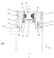
- FIG. 3 shows an rZ sectional view of the first rotating electric machine 200 of FIG.
- the first rotating electrical machine 200 and the second rotating electrical machine 202 have substantially the same structure, and the structure of the first rotating electrical machine 200 will be described below as a representative example. However, the structure shown below does not have to be employed in both the first rotating electrical machine 200 and the second rotating electrical machine 202, and may be employed in only one of them.
- a stator 230 is held inside the housing 212.
- the stator 230 includes a stator core 232 and a stator winding 238.
- a rotor 280 (see FIG. 4) is rotatably held via a gap 222.
- the rotor 280 includes a rotor core 282 fixed to the shaft 218, a permanent magnet 284, and a non-magnetic contact plate 226.
- the housing 212 has a pair of end brackets 214 provided with bearings 216, and the shaft 218 is rotatably held by these bearings 216.
- the shaft 218 is provided with a resolver 224 that detects the position and rotation speed of the pole of the rotor 280.
- the output from the resolver 224 is taken into the control circuit 648 shown in FIG.
- the control circuit 648 outputs a control signal to the first drive circuit 652 based on the fetched output.
- the first drive circuit 652 outputs a drive signal based on the control signal to the power module 610.
- the power module 610 performs a switching operation based on the control signal, and converts DC power supplied from the battery 180 into three-phase AC power. This three-phase AC power is supplied to the stator winding 238 shown in FIG. 3 and a rotating magnetic field is generated in the stator 230.
- the frequency of the three-phase alternating current is controlled based on the output value of the resolver 224, and the phase of the three-phase alternating current with respect to the rotor 280 is also controlled based on the output value of the resolver 224.
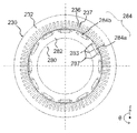
- FIG. 4 is a view showing the r- ⁇ cross section of the stator 230 and the rotor 280, and shows the AA cross section of FIG.
- FIG. 4 the housing 212, the shaft 218, and the stator winding 238 are not shown.
- a large number of slots 237 and teeth 236 are arranged uniformly over the entire circumference.
- all slots and teeth are not labeled, and only some teeth and slots are represented by symbols.
- a slot insulating material (not shown) is provided in the slot 237, and a plurality of phase windings of U phase, V phase, and W phase constituting the stator winding 238 of FIG.
- the number of slots per phase per pole is 2, 72 slots 237 are formed at equal intervals.
- the number of slots per phase per pole is two for the U phase, V phase, and W phase of each slot 237 in the ⁇ direction: U phase, U phase, V phase, V phase, W phase, W phase,.
- the phases are arranged so that they are lined up one by one, and six slots 237 are used in one pole U phase, V phase, and W phase.
- 12 permanent magnets 284 described later are 12 poles arranged in the ⁇ direction
- the number of slots 237 of the stator core 232 is 72 of 6 ⁇ 12.
- a plurality of holes 283 for inserting rectangular magnets are arranged at equal intervals along the ⁇ direction.
- Each hole 283 is formed along the z direction, and a permanent magnet 284 is embedded in each hole 283 and fixed with an adhesive or the like.
- the width of the hole 283 in the ⁇ direction is set to be larger than the width of the permanent magnet 284 (284a, 284b) in the ⁇ direction, and the hole space 287 on both sides of the permanent magnet 284 functions as a magnetic gap.
- the hole space 287 may be embedded with an adhesive, or may be solidified integrally with the permanent magnet 284 with a molding resin.
- the permanent magnet 284 acts as a field pole of the rotor 280 and has a 12-pole configuration in this embodiment.
- the magnetization direction of the permanent magnet 284 faces the radial direction, and the direction of the magnetization direction is reversed for each field pole. That is, if the stator side surface of the permanent magnet 284a is N-pole and the surface on the shaft side is S-pole, the stator side surface of the adjacent permanent magnet 284b is S-pole and the surface on the shaft side is N-pole. . These permanent magnets 284a and 284b are alternately arranged in the ⁇ direction.
- the permanent magnet 284 may be inserted into the hole 283 after being magnetized, or may be magnetized by applying a strong magnetic field after being inserted into the hole 283 of the rotor core 282.
- the magnetized permanent magnet 284 is a strong magnet, if the magnet is magnetized before fixing the permanent magnet 284 to the rotor 280, a strong attractive force between the rotor core 282 and the permanent magnet 284 is fixed. Occurs and hinders assembly work. Further, due to the strong attractive force of the permanent magnet 284, dust such as iron powder may adhere to the permanent magnet 284. Therefore, when considering the productivity of the rotating electrical machine, it is preferable that the permanent magnet 284 is magnetized after being inserted into the rotor core 282.
- the permanent magnet 284 can be a neodymium-based or samarium-based sintered magnet, a ferrite magnet, a neodymium-based bond magnet, or the like.
- the residual magnetic flux density of the permanent magnet 284 is about 0.4 to 1.4T.
- the alternating current since the alternating current is controlled to be sinusoidal, the product of the fundamental wave component of the interlinkage magnetic flux and the fundamental wave component of the alternating current becomes the time-average component of the torque, and the harmonic component of the interlinkage magnetic flux
- the product of the fundamental wave components of the alternating current becomes the torque ripple that is the harmonic component of the torque. That is, in order to reduce the torque ripple, the harmonic component of the flux linkage may be reduced.
- the harmonic component of the interlinkage magnetic flux since the product of the interlinkage magnetic flux and the angular velocity at which the rotor rotates is the induced voltage, reducing the harmonic component of the interlinkage magnetic flux is equivalent to reducing the harmonic component of the induced voltage.
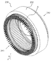
- FIG. 5 is a perspective view of the stator 230.
- a plurality of substantially U-shaped segment coils 243 are used for the stator core 232, and the stator winding 238 is formed by wave winding in which the segment coil 243 is wound in a wave shape.
- the connection side coil end 241 for connecting the terminal portion of the segment coil 243
- a non-connection side coil end 242 formed by a U-shaped bottom portion of the segment coil 243. Is formed.
- FIG. 6 is an enlarged schematic view of the r- ⁇ cross section of one slot of the stator 230, and a simplified diagram in which the slot insulating material provided between the stator core 232 and the segment coil 243 is omitted.
- segment coils 243 are arranged in the stator core 232 so as to form a plurality of layers.
- layers 1 to 8 are arranged in order from the inner circumference side (lower part in the figure) in the r direction.
- the non-connection side coil end 242 is composed of four winding groups.
- the first winding group 242a is layer 1 and layer 2
- the second winding group 242b is layer 3 and layer 4, and the third winding group.
- 242c is inserted in layers 5 and 6
- the fourth winding group 242d is inserted in layers 7 and 8.
- a segment coil having a square cross section is used, but a segment coil having a round cross section may be used.
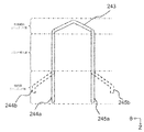
- FIG. 7A is a view of the segment coil 243 before being assembled to the stator core 232 as seen from the inner peripheral side of the stator core 232.
- the r- ⁇ cross section shown in FIG. 6 is a cross sectional view of a portion corresponding to the insertion portion of the slot 237 shown in FIG.
- the segment coil 243 has a substantially U shape.
- the terminal portion 244a is inserted into the layer 1 and the terminal portion 245a is inserted into the layer 2.
- the terminal portion 244a inserted into the layer 1 is twisted in the left direction ⁇ like the terminal portion 244b shown by a broken line, and the terminal portion 245a inserted into the layer 2 is broken. Is twisted in the right direction of ⁇ like a terminal portion 245b shown in FIG.
- the terminal portion 244b after twisting and the terminal portion 245b after twisting are arranged in the r direction (244b is the layer 1, 245b is the layer 2), when viewed in the ⁇ direction A wave-like wave winding is formed.
- the terminal portion 244a is layer 3
- the terminal portion 245a is layer 4
- the third winding group is the terminal portion 244a is layer 5
- the terminal portion 245a is layer 6, and the fourth winding group is the terminal portion.
- the layer 244a is inserted into the layer 7 and the terminal unit 245a is inserted into the layer 8, the odd layer is twisted as the terminal unit 244b, and the even layer is twisted as the terminal unit 245b.
- the terminal unit 244a entering the odd layer and the terminal unit 245a entering the even layer may be reversed.
- FIG. 8 is a perspective view seen from the connection side coil end 241 of the stator 230.
- each layer is twisted at the same slot pitch.
- each layer is twisted at a pitch of 3 slots.
- the odd layers of Layer 1, Layer 3, Layer 5, and Layer 7 are twisted clockwise, and Layer 2 and Layer 4
- the even layers of layer 6 and layer 8 are twisted counterclockwise.
- the terminal portions 244b and 245b of the segment coil 243 of each layer are connected, the total pitch is 6 slots.
- the twisting is performed by dividing the 6-slot pitch into each layer 3 slot pitch. For example, the odd layers of layer 1, layer 3, layer 5, and layer 7 are twisted by 2 slots, and layer 2 and layer 4 are twisted. If the even layers of layer 6 and layer 8 are twisted and formed into a 4-slot pitch to obtain a 6-slot pitch, not all layers need to have the same slot pitch. However, after twist forming, in order to connect the terminal portion 244b and the terminal portion 245b of the segment coil 243, it is desirable to set the slot pitch so that the terminal portion 244b and the terminal portion 245b are aligned in a straight line in the r direction.
- FIG. 9 is an enlarged view of the range shown in A of FIG.
- terminal units other than the terminal unit connected to the U-phase, V-phase, and W-phase current sensors 660 and the terminal unit serving as a neutral point layer 1 and layer 2, layer 3 and layer 4, layer 5 and layer 6, and layer 7 1n and the layer 8 are connected to each other, and a first connection group 246a is formed which is connected so that four connection portions are arranged in the radial direction. By making this connection, each winding group is electrically connected.
- the layer 2 and the layer 3, the layer 4 and the layer 5, the layer 6 and the layer 7, and the layer 2n + 1 are connected, and a second connection group 246b is formed which is connected so that three connection portions are arranged in the radial direction.
- the remaining layer 1 and layer 8 become the U phase, V phase, W phase, and neutral point connected to the current sensor 660.
- independent winding groups are electrically connected to each other and are connected to the current sensor 660.
- the terminals connected to the U-phase, V-phase, and W-phase current sensors 660 are connected to the U1 phase lead wire 247a, the U2 phase lead wire 247j, the V1 phase lead wire 247c, There are two V2-phase lead wires 247n, W1 phase lead wires 247h, and W2-phase lead wires 247e.
- the neutral points for forming the star connection are the U1 phase neutral point 247g, the U2 phase neutral point 247d, and V1. There are one phase neutral point 247i, one V2 phase neutral point 247f, one W1 phase neutral point 247b, and one W2 phase neutral point 247k, and a total of 12 lead wires are drawn.
- each is not yet connected.
- the connection to the current sensor 660 it is possible to pull it out to a place where it is desired to pull it out later by using another member.
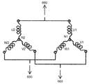
- FIG. 10 is a connection diagram of the stator winding 238, showing the connection method and the electrical phase relationship of each phase winding.
- double star connection is adopted for the stator winding 238 of the present embodiment, and a first star connection comprising a U1 phase winding group, a V1 phase winding group, and a W1 phase winding group,
- a second star connection composed of a U2-phase winding group, a V2-phase winding group, and a W2-phase winding group is connected in parallel.
- the first star connection and the second star connection are U phases (U1 phase lead wire 247a and U2 phase lead wire 247j in FIG. 9) and V phases (V1 phase lead wire in FIG. 9).
- 247c, V2 phase lead wire 247n), and W phases (W1 phase lead wire 247h, W2 phase lead wire 247e) are electrically connected, and the connection is connected to the current sensor 660.
- U1, V1, and W1 are connected at a neutral point N1 (U1 phase neutral point 247g, V1 phase neutral point 247i, and W1 phase neutral point 247b in FIG. 9), and U2 , V2 and W2 are electrically connected by being connected at a neutral point N2 (U2 phase neutral point 247d, V2 phase neutral point 247f and W2 phase neutral point 247k in FIG. 9).
- N1 U1 phase neutral point 247g, V1 phase neutral point 247i, and W1 phase neutral point 247b in FIG. 9
- N2 U2 phase neutral point 247d, V2 phase neutral point 247f and W2 phase neutral point 247k in FIG. 9
- the neutral point N1 and the neutral point N2 are not connected, but may be connected.
- the V phase and the W phase have substantially the same configuration as the U phase, and are arranged so that the phase of the voltage induced in each phase is shifted by 120 degrees in electrical angle.
- the stator winding 238 employs a double star (2Y) connection connected in parallel. However, depending on the driving voltage of the rotating electrical machine, they may be connected in series to form a single star (1Y) connection. good.
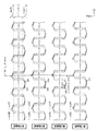
- FIG. 11 is a diagram showing a detailed connection of U1 in FIG. 10, as viewed from the inner peripheral side of the stator core 232.
- 72 slots 237 are formed in the stator core 232 (see FIG. 4), and reference numerals 01, 02,..., 71, 72 shown in FIG.
- the upper part of the slot number corresponds to the connection side coil end 241
- the lower part corresponds to the non-connection side coil end 242.
- connection side coil end 241 When one turn is taken from the connection point 252 in the winding group indicated by a circle (circle symbol in FIG. 11) to the connection point 252 in the adjacent winding group, the connection side coil end 241 has a 6-slot pitch, the non-connection side coil. After the end 242 is wound for 5 turns at a 6-slot pitch, only the non-connection side coil end 242 is wound with a 5-slot segment coil 248, which is shorter by 1 slot pitch, so that the number of slots per phase is 2. turn. Then, the slot number 02 next to the segment coil that entered the first slot number 01 is entered, and the number of slots per phase per pole is 2.
- connection point 253 indicated by a square (symbol ⁇ ). *
- both the connection side coil end 241 and the non-connection side coil end 242 are wound in the 6-slot segment coil in the right direction ( ⁇ direction) in FIG. Only the side coil end 242 is wound with the 5-slot pitch segment coil 248 for one turn, and after the 6-slot pitch segment coil is again wound with 5 turns, the non-connection side coil end 242 has a 7-slot pitch segment coil 249.
- connection point 255 indicated by a triangle (symbol ⁇ )
- the U1-phase neutral point 247g is drawn from the eleventh first winding group, and the U1-phase winding group is completed.
- FIG. 11 there are three types of slot pitches in the anti-connection side coil ends 242 in each winding group, but all the connection side coil end portions have a 6-slot pitch. Therefore, the connection points 252 in the winding group indicated by ⁇ are aligned in the r direction and correspond to the first connection group 246a shown in FIG.
- connection point 253, a connection point 254, and a connection point 255 that connect the winding groups indicated by ⁇ ⁇ ⁇ are also arranged in the r direction, and the terminal portions that exit from the layer 1 and the layer 8 are in the U1 phase lead wire 247a and the U1 phase. It becomes a sex point 247g and corresponds to the second connection group 246b shown in FIG. FIG. 11 shows the detailed connection of U1, but it has the same configuration except that U2 and slots 237 into which all of V1, V2, W1, and W2 enter are different.
- connection side coil end 241 when the number of slots per phase per pole is two or more, a plurality of slot pitches are required for either the connection side coil end 241 or the non-connection side coil end 242, as in this embodiment.
- the slot pitch of the connection side coil end 241 can be made the same.
- the molding process can be performed at once, and the process can be simplified. In this embodiment, there is a configuration from the first winding group to the fourth winding group, but if there are two or more winding groups, the same configuration as the present invention can be adopted.
- 5 turns of the non-connection side coil end 242 in the winding group of U1 are set to 6 slot pitches, and the number of slots per phase per pole is set to 2 to 5 slot pitches per turn.
- the connection is made when the slot pitch is used and all the connection side coil ends 241 are set to 6 slot pitch.
- 5 turns of the non-connection side coil end 242 is set to 7 slot pitch, and the number of slots per phase per pole is 2. Therefore, the configuration of the present invention can also be adopted as a connection when a 6-slot pitch and an 8-slot pitch are used for each turn and all the connection-side coil ends 241 have a 5-slot pitch.
- the number of slots per phase per pole is 2, but the same configuration can be adopted as long as it is 2 or more.
- the segment coil 248 having a 5-slot pitch in each winding group enters two turns, and the segment coil 249 having a 7-slot pitch that is the final turn in the winding group is set to 8 turns.
- the same slot number is returned to that at the beginning of winding, and the same configuration is obtained.
- the segment coils of layer 1 to layer 4 are in slot numbers 01 and 72
- the segment coils of layer 5 to layer 8 are in slot numbers 02 and 01.
- the arrangement of the coils for example, by adjusting the location where the second winding group and the third winding group are connected, it is possible to make all the windings into slot numbers 01 and 72 from layer 1 to layer 8. It becomes possible.
- FIG. 12 is a diagram showing the detailed connection of U1 in a combination different from FIG.
- all the connection side coil ends 241 have a 6-slot pitch
- the counter-connection side coil ends 242 have a 5, 6, 7-slot pitch.
- the first winding group and the fourth winding group in FIG. 12 have a 7-slot pitch for 5 turns of the non-connection side coil end 242 and the number of slots per phase per pole is 2.
- the connection-side coil end 241 is connected using a 5-slot pitch with a 6-slot pitch and an 8-slot pitch for one turn.
- the first winding group and the fourth winding group are different in 5 slot pitch
- the second winding group and the third winding group are different in 6 slot pitch and slot pitch.
- the twist pitch of the 5-slot pitch of the group and the fourth winding group the layer 7 and the layer 1 are divided into the 2-slot pitch and the layer 8 and the layer 2 are divided into the 3-slot pitch.
- the first connection group and the second connection group can be arranged in the direction, and the winding groups can be connected without using a separate member. In this way, the slot pitch is different for each winding group, but the same slot pitch is used for each layer, so twisting can be performed at the same time. Obtainable.
- FIG. 13 (a) is a perspective view of the stator 230
- FIG. 13 (b) is an enlarged view of a portion B of FIG. 13 (a), and one for each winding group shown in the connection diagram of FIG. It is an enlarged view of a portion of a segment coil 248 having a 5-slot pitch and a segment coil 249 having a 7-slot pitch provided for each type.
- the 5-slot pitch segment coil 248 and the 7-slot segment coil 249 are provided so as to be arranged vertically in the z direction.
- a 6-slot pitch segment coil, a 5-slot pitch segment coil 248, and a 7-slot pitch segment coil 249 assembled in a plurality around the entire circumference have the same shape and segment coil shape of the manufacturing method. And it is possible to make it compact so that the non-connection side coil end does not travel in the r direction.
- the segment coil 249 having a 7-slot pitch is formed in a segment coil shape that is arranged in the r-direction, that is, the outer peripheral side of the non-connection side coil end 242 instead of the z-direction, the segment coil having a 7-slot pitch among a plurality of segment coils Only 249 must be molded in a variety of ways so as to avoid other segment coils, which increases the difficulty of manufacturing the segment coils.
- the present invention is not limited to the above-described embodiment, and includes various modifications.
- the above-described embodiment has been described in detail for easy understanding of the present invention, and is not necessarily limited to one having all the configurations described.
- a part of the configuration of an embodiment can be replaced with the configuration of another embodiment, and the configuration of another embodiment can be added to the configuration of an embodiment.
- capacitor module 642 ... connector board, 644 ... transmission / reception circuit, 646 ... Control circuit board, 648 ... Control circuit, 650 ... Drive circuit board, 652 ... First drive circuit, 654 ... Drive circuit board, 656 ... Second drive circuit, 660 ... Current sensor, 662 ... Current sensor, N1 ... Neutral point, N2 ... Neutral point
Landscapes
- Engineering & Computer Science (AREA)
- Power Engineering (AREA)
- Windings For Motors And Generators (AREA)
- Manufacture Of Motors, Generators (AREA)
- Insulation, Fastening Of Motor, Generator Windings (AREA)
Abstract
Description
Claims (7)
- ステータコアの一方側に配置されかつスロットに対して同一のスロットピッチで接続され接続側巻線部と、
前記ステータコアの他方側に配置されかつ前記スロットに対して複数種のスロットピッチで挿入される反接続側巻線部と、を有する複数のセグメントコイルを備え、
前記接続側巻線部において、
前記複数のセグメントコイル同士を接続する複数の端末部が設けられる第1接続群と、
前記第1接続群とは異なる層間を接続しかつ複数の端末部が設けられる第2接続群と、を有する回転電機の固定子。 - 請求項1に記載された回転電機の固定子であって、
前記接続側巻線部は、前記スロットに対して前記ステータコアの径方向の前記セグメントコイル各層ごとに円周方向に同一のスロットピッチで接続される回転電機の固定子。 - 請求項1または2に記載された回転電機の固定子であって、
前記接続側巻線部側に設けられる出力線と、を有する回転電機の固定子。 - 請求項1ないし3に記載されたいずれかの回転電機の固定子であって、
n=1以上であって、
前記第1接続群は、2n-1層と2n層のセグメント同士の前記端末部を接続し、
前記第2接続群は、2n層と2n+1層のセグメント同士の前記端末部を接続する回転電機の固定子。 - 請求項3に記載された回転電機の固定子であって、
前記第1接続群の複数の前記端末部は、径方向に沿って並べられ、
前記出力線と前記第2接続群の複数の前記端末部は、径方向に沿って並べられる回転電機の固定子。 - 請求項5に記載された回転電機の固定子であって、
前記出力線は、径方向の最外周側または最内周側に配置される回転電機の固定子。 - 請求項1ないし6にいずれかの回転電機の固定子を備える回転電機。
Priority Applications (7)
| Application Number | Priority Date | Filing Date | Title |
|---|---|---|---|
| CN202010552878.1A CN111682673B (zh) | 2016-03-31 | 2017-01-19 | 旋转电机的定子以及使用它的旋转电机 |
| DE112017000288.5T DE112017000288B4 (de) | 2016-03-31 | 2017-01-19 | Stator für elektrische Rotationsmaschine und elektrische Rotationsmaschine, die ihn verwendet |
| US16/072,396 US11245299B2 (en) | 2016-03-31 | 2017-01-19 | Stator for rotary electric machine and rotary electric machine using same |
| CN201780004017.6A CN108886288B (zh) | 2016-03-31 | 2017-01-19 | 旋转电机的定子以及使用它的旋转电机 |
| JP2018508421A JP6585826B2 (ja) | 2016-03-31 | 2017-01-19 | 回転電機の固定子及びそれを用いた回転電機 |
| US17/220,170 US11811284B2 (en) | 2016-03-31 | 2021-04-01 | Stator for rotary electric machine and rotary electric machine using same |
| US18/373,156 US20240030770A1 (en) | 2016-03-31 | 2023-09-26 | Stator for Rotary Electric Machine and Rotary Electric Machine Using Same |
Applications Claiming Priority (2)
| Application Number | Priority Date | Filing Date | Title |
|---|---|---|---|
| JP2016-069949 | 2016-03-31 | ||
| JP2016069949 | 2016-03-31 |
Related Child Applications (2)
| Application Number | Title | Priority Date | Filing Date |
|---|---|---|---|
| US16/072,396 A-371-Of-International US11245299B2 (en) | 2016-03-31 | 2017-01-19 | Stator for rotary electric machine and rotary electric machine using same |
| US17/220,170 Continuation US11811284B2 (en) | 2016-03-31 | 2021-04-01 | Stator for rotary electric machine and rotary electric machine using same |
Publications (1)
| Publication Number | Publication Date |
|---|---|
| WO2017168971A1 true WO2017168971A1 (ja) | 2017-10-05 |
Family
ID=59964099
Family Applications (1)
| Application Number | Title | Priority Date | Filing Date |
|---|---|---|---|
| PCT/JP2017/001624 Ceased WO2017168971A1 (ja) | 2016-03-31 | 2017-01-19 | 回転電機の固定子及びそれを用いた回転電機 |
Country Status (5)
| Country | Link |
|---|---|
| US (3) | US11245299B2 (ja) |
| JP (3) | JP6585826B2 (ja) |
| CN (2) | CN108886288B (ja) |
| DE (1) | DE112017000288B4 (ja) |
| WO (1) | WO2017168971A1 (ja) |
Cited By (7)
| Publication number | Priority date | Publication date | Assignee | Title |
|---|---|---|---|---|
| US10707713B2 (en) | 2018-01-15 | 2020-07-07 | Ford Global Technologies, Llc | Balanced hairpin winding electric machine |
| US10998787B2 (en) | 2018-03-13 | 2021-05-04 | Ford Global Technologies, Llc | Hairpin winding electric machine with staggered hairpin connections |
| US11056954B2 (en) | 2018-11-28 | 2021-07-06 | Ford Global Technologies, Llc | Hairpin winding electric machine with multi-conductor hairpin assemblies |
| DE112021006414T5 (de) | 2021-03-29 | 2023-09-21 | Hitachi Astemo, Ltd. | Stator für eine drehende elektrische maschine und drehende elektrische maschine |
| DE112024003647T5 (de) | 2023-12-28 | 2026-07-30 | Komatsu Ltd. | Stator, rotierende elektrische maschine und arbeitsmaschine |
| DE112025000217T5 (de) | 2024-01-31 | 2026-08-06 | Komatsu Ltd. | Elektrische Rotationsmaschine und Arbeitsmaschine |
| DE112025000204T5 (de) | 2024-01-29 | 2026-08-06 | Komatsu Ltd. | Rotor, rotierende elektrische Maschine und Arbeitsmaschine |
Families Citing this family (7)
| Publication number | Priority date | Publication date | Assignee | Title |
|---|---|---|---|---|
| DE112017000288B4 (de) * | 2016-03-31 | 2025-07-31 | Hitachi Astemo, Ltd. | Stator für elektrische Rotationsmaschine und elektrische Rotationsmaschine, die ihn verwendet |
| US11431188B1 (en) * | 2016-12-29 | 2022-08-30 | Hive Energy Systems Llc | System for highly efficient transfer of energy produced by Photovoltaic panels into batteries for storage |
| KR102342561B1 (ko) * | 2017-04-19 | 2021-12-23 | 엘지마그나 이파워트레인 주식회사 | 회전전기기기의 스테이터 |
| US11539255B2 (en) | 2020-03-24 | 2022-12-27 | Ford Global Technologies, Llc | Hairpin winding electric machine |
| US11309761B2 (en) * | 2020-03-24 | 2022-04-19 | Ford Global Technologies, Llc | Hairpin winding electric machine |
| US11368066B2 (en) * | 2020-04-03 | 2022-06-21 | Ford Global Technologies, Llc | Hairpin winding electric machine |
| CN114400841B (zh) * | 2022-01-24 | 2024-02-13 | 芜湖清川电气有限公司 | 一种伺服电机定子接线装置及工艺 |
Citations (7)
| Publication number | Priority date | Publication date | Assignee | Title |
|---|---|---|---|---|
| JP3988617B2 (ja) * | 2002-09-18 | 2007-10-10 | 株式会社デンソー | セグメント導体接合型電機子及びこの電機子を備えた交流機 |
| WO2007146252A2 (en) * | 2006-06-12 | 2007-12-21 | Remy International, Inc. | Terminals and connections between multi-set segmented hairpin windings |
| US20090140596A1 (en) * | 2007-11-30 | 2009-06-04 | Gm Global Technology Operations, Inc. | Methods and apparatus for a bar-wound stator with parallel connections |
| WO2012011493A1 (ja) * | 2010-07-20 | 2012-01-26 | 日立オートモティブシステムズ株式会社 | 回転電機、およびその回転電機を備えた車両 |
| JP2012222874A (ja) * | 2011-04-05 | 2012-11-12 | Denso Corp | 回転電機の固定子 |
| WO2013108680A1 (ja) * | 2012-01-19 | 2013-07-25 | 日立オートモティブシステムズ株式会社 | 回転電機、およびその回転電機を備えた車両 |
| US20140319953A1 (en) * | 2013-04-24 | 2014-10-30 | GM Global Technology Operations LLC | Bar wound stator winding layout with long-pitched and short-pitched coils |
Family Cites Families (24)
| Publication number | Priority date | Publication date | Assignee | Title |
|---|---|---|---|---|
| JP3405280B2 (ja) | 1997-05-26 | 2003-05-12 | 株式会社デンソー | 車両用交流発電機 |
| JP3384337B2 (ja) * | 1998-09-07 | 2003-03-10 | 株式会社デンソー | 車両用交流発電機の固定子 |
| JP3199068B2 (ja) | 1999-03-31 | 2001-08-13 | 株式会社デンソー | ステータの製造装置 |
| JP2001161050A (ja) * | 1999-11-30 | 2001-06-12 | Denso Corp | 液冷型車両用回転電機 |
| JP3155532B1 (ja) * | 1999-12-01 | 2001-04-09 | 三菱電機株式会社 | 車両用交流発電機の固定子 |
| DE10103935A1 (de) * | 2000-02-03 | 2001-08-09 | Denso Corp | Statoranordnung einer elektrischen Umlaufmaschine für ein Fahrzeug |
| FR2819117B1 (fr) * | 2000-12-21 | 2004-10-29 | Valeo Equip Electr Moteur | Alternateur a elements conducteurs en epingle pour vehicule automobile |
| JP2003134711A (ja) | 2001-10-25 | 2003-05-09 | Toyota Motor Corp | 回転電機および相コイルの結線方法 |
| DE10362345B3 (de) * | 2002-05-15 | 2018-01-25 | Remy Inc. | Wicklungen aus rechtwinkligen Kupferhaarnadeln in mehreren Sätzen für elektrische Maschinen |
| US20030214190A1 (en) | 2002-05-15 | 2003-11-20 | Delco Remy America | Connection device for hairpin wound electric machines |
| JP3741081B2 (ja) | 2002-06-12 | 2006-02-01 | 株式会社デンソー | 回転電機のセグメント順次接合型ステータコイル |
| JP3815394B2 (ja) | 2002-07-29 | 2006-08-30 | 株式会社デンソー | 導体セグメント成形装置 |
| US7348705B2 (en) | 2005-07-21 | 2008-03-25 | Remy Technologies, L.L.C. | Multi-phase fractional slot windings for electric machines having segmented bar-shaped windings |
| JP5704418B2 (ja) | 2009-07-17 | 2015-04-22 | 株式会社デンソー | 回転電機の固定子 |
| IT1401829B1 (it) * | 2010-09-29 | 2013-08-28 | Magneti Marelli Spa | Macchina elettrica presentante un avvolgimento statorico con barre rigide e relativo metodo di costruzione |
| JP5712660B2 (ja) | 2011-02-18 | 2015-05-07 | トヨタ自動車株式会社 | ステータ製造方法 |
| JP2013090437A (ja) | 2011-10-18 | 2013-05-13 | Mitsuba Corp | 電動モータ |
| JP2013121183A (ja) | 2011-12-06 | 2013-06-17 | Toyota Motor Corp | 回転電機 |
| US20130156071A1 (en) * | 2011-12-16 | 2013-06-20 | Remy Technologies, Llc | Electric Machine Including Insulated Slot Liner With Temperature Sensor |
| US20140033514A1 (en) * | 2012-08-06 | 2014-02-06 | Remy Technologies, Llc | Electric machine with single or dual-shape winding configuration and method |
| JP6118594B2 (ja) | 2013-03-15 | 2017-04-19 | 日立オートモティブシステムズ株式会社 | コイル、それを備えた回転電機、及びその製造方法 |
| JP5896250B2 (ja) | 2013-09-18 | 2016-03-30 | 株式会社デンソー | 回転電機の固定子 |
| JP6160397B2 (ja) * | 2013-09-20 | 2017-07-12 | トヨタ自動車株式会社 | 回転電機ステータ |
| DE112017000288B4 (de) * | 2016-03-31 | 2025-07-31 | Hitachi Astemo, Ltd. | Stator für elektrische Rotationsmaschine und elektrische Rotationsmaschine, die ihn verwendet |
-
2017
- 2017-01-19 DE DE112017000288.5T patent/DE112017000288B4/de active Active
- 2017-01-19 CN CN201780004017.6A patent/CN108886288B/zh active Active
- 2017-01-19 JP JP2018508421A patent/JP6585826B2/ja active Active
- 2017-01-19 CN CN202010552878.1A patent/CN111682673B/zh active Active
- 2017-01-19 WO PCT/JP2017/001624 patent/WO2017168971A1/ja not_active Ceased
- 2017-01-19 US US16/072,396 patent/US11245299B2/en active Active
-
2019
- 2019-09-05 JP JP2019162153A patent/JP7159131B2/ja active Active
-
2021
- 2021-04-01 US US17/220,170 patent/US11811284B2/en active Active
- 2021-06-30 JP JP2021109464A patent/JP2021177695A/ja active Pending
-
2023
- 2023-09-26 US US18/373,156 patent/US20240030770A1/en active Pending
Patent Citations (7)
| Publication number | Priority date | Publication date | Assignee | Title |
|---|---|---|---|---|
| JP3988617B2 (ja) * | 2002-09-18 | 2007-10-10 | 株式会社デンソー | セグメント導体接合型電機子及びこの電機子を備えた交流機 |
| WO2007146252A2 (en) * | 2006-06-12 | 2007-12-21 | Remy International, Inc. | Terminals and connections between multi-set segmented hairpin windings |
| US20090140596A1 (en) * | 2007-11-30 | 2009-06-04 | Gm Global Technology Operations, Inc. | Methods and apparatus for a bar-wound stator with parallel connections |
| WO2012011493A1 (ja) * | 2010-07-20 | 2012-01-26 | 日立オートモティブシステムズ株式会社 | 回転電機、およびその回転電機を備えた車両 |
| JP2012222874A (ja) * | 2011-04-05 | 2012-11-12 | Denso Corp | 回転電機の固定子 |
| WO2013108680A1 (ja) * | 2012-01-19 | 2013-07-25 | 日立オートモティブシステムズ株式会社 | 回転電機、およびその回転電機を備えた車両 |
| US20140319953A1 (en) * | 2013-04-24 | 2014-10-30 | GM Global Technology Operations LLC | Bar wound stator winding layout with long-pitched and short-pitched coils |
Cited By (9)
| Publication number | Priority date | Publication date | Assignee | Title |
|---|---|---|---|---|
| US10707713B2 (en) | 2018-01-15 | 2020-07-07 | Ford Global Technologies, Llc | Balanced hairpin winding electric machine |
| US10998787B2 (en) | 2018-03-13 | 2021-05-04 | Ford Global Technologies, Llc | Hairpin winding electric machine with staggered hairpin connections |
| US11056954B2 (en) | 2018-11-28 | 2021-07-06 | Ford Global Technologies, Llc | Hairpin winding electric machine with multi-conductor hairpin assemblies |
| US11955851B2 (en) | 2018-11-28 | 2024-04-09 | Ford Global Technologies, Llc | Hairpin winding electric machine with multi-conductor hairpin assemblies |
| DE112021006414T5 (de) | 2021-03-29 | 2023-09-21 | Hitachi Astemo, Ltd. | Stator für eine drehende elektrische maschine und drehende elektrische maschine |
| US12658755B2 (en) | 2021-03-29 | 2026-06-16 | Hitachi Astemo, Ltd. | Stator for rotary electric machine and rotary electric machine |
| DE112024003647T5 (de) | 2023-12-28 | 2026-07-30 | Komatsu Ltd. | Stator, rotierende elektrische maschine und arbeitsmaschine |
| DE112025000204T5 (de) | 2024-01-29 | 2026-08-06 | Komatsu Ltd. | Rotor, rotierende elektrische Maschine und Arbeitsmaschine |
| DE112025000217T5 (de) | 2024-01-31 | 2026-08-06 | Komatsu Ltd. | Elektrische Rotationsmaschine und Arbeitsmaschine |
Also Published As
| Publication number | Publication date |
|---|---|
| US11245299B2 (en) | 2022-02-08 |
| US11811284B2 (en) | 2023-11-07 |
| JPWO2017168971A1 (ja) | 2018-08-09 |
| US20190044403A1 (en) | 2019-02-07 |
| JP2019205352A (ja) | 2019-11-28 |
| US20240030770A1 (en) | 2024-01-25 |
| JP2021177695A (ja) | 2021-11-11 |
| US20210328473A1 (en) | 2021-10-21 |
| CN108886288B (zh) | 2020-07-14 |
| DE112017000288B4 (de) | 2025-07-31 |
| CN111682673B (zh) | 2023-11-17 |
| JP7159131B2 (ja) | 2022-10-24 |
| CN111682673A (zh) | 2020-09-18 |
| DE112017000288T5 (de) | 2018-09-20 |
| CN108886288A (zh) | 2018-11-23 |
| JP6585826B2 (ja) | 2019-10-02 |
Similar Documents
| Publication | Publication Date | Title |
|---|---|---|
| JP7159131B2 (ja) | 回転電機の固定子の製造方法、回転電機の製造方法 | |
| US10797550B2 (en) | Rotary electric machine and vehicle provided with the same | |
| US10868448B2 (en) | Dynamo-electric machine and vehicle | |
| US9735640B2 (en) | Rotating electrical machine and vehicle equipped with rotating electrical machine | |
| US9425666B2 (en) | Stator and rotating electric machine | |
| US11735968B2 (en) | Rotary electric machine and vehicle provided with the same | |
| JP7113003B2 (ja) | 回転電機の回転子及びこれを備えた回転電機 | |
| JP6768672B2 (ja) | 回転電機の回転子、回転電機、及び車両 | |
| US20110273128A1 (en) | Synchronous motor and system for driving synchronous motor | |
| JP7532645B2 (ja) | 回転電機の固定子、回転電機 | |
| JP6670767B2 (ja) | 回転電機 | |
| JP6626768B2 (ja) | 回転電機の固定子、及びこれを備えた回転電機 | |
| JP2016158401A (ja) | 回転電機の回転子、及びこれを備えた回転電機 | |
| JP2025014651A (ja) | 回転電機の固定子、及びそれを備えた回転電機 | |
| WO2024232250A1 (ja) | 回転電機 |
Legal Events
| Date | Code | Title | Description |
|---|---|---|---|
| ENP | Entry into the national phase |
Ref document number: 2018508421 Country of ref document: JP Kind code of ref document: A |
|
| WWE | Wipo information: entry into national phase |
Ref document number: 112017000288 Country of ref document: DE |
|
| 121 | Ep: the epo has been informed by wipo that ep was designated in this application |
Ref document number: 17773521 Country of ref document: EP Kind code of ref document: A1 |
|
| 122 | Ep: pct application non-entry in european phase |
Ref document number: 17773521 Country of ref document: EP Kind code of ref document: A1 |
|
| WWG | Wipo information: grant in national office |
Ref document number: 112017000288 Country of ref document: DE |