WO2017168938A1 - レンズ装置及びレンズ装置の製造方法 - Google Patents
レンズ装置及びレンズ装置の製造方法 Download PDFInfo
- Publication number
- WO2017168938A1 WO2017168938A1 PCT/JP2017/000865 JP2017000865W WO2017168938A1 WO 2017168938 A1 WO2017168938 A1 WO 2017168938A1 JP 2017000865 W JP2017000865 W JP 2017000865W WO 2017168938 A1 WO2017168938 A1 WO 2017168938A1
- Authority
- WO
- WIPO (PCT)
- Prior art keywords
- lens
- adhesive
- protrusion
- tip
- lens device
- Prior art date
- Legal status (The legal status is an assumption and is not a legal conclusion. Google has not performed a legal analysis and makes no representation as to the accuracy of the status listed.)
- Ceased
Links
Images






Classifications
-
- G—PHYSICS
- G02—OPTICS
- G02B—OPTICAL ELEMENTS, SYSTEMS OR APPARATUS
- G02B7/00—Mountings, adjusting means, or light-tight connections, for optical elements
- G02B7/02—Mountings, adjusting means, or light-tight connections, for optical elements for lenses
Definitions
- the present invention relates to a lens device and a manufacturing method of the lens device.
- a lens device used in an in-vehicle camera a camera mounted on a portable terminal such as a smartphone, or an optical device such as an optical pickup, the lens is bonded to another lens, or an interval ring interposed between the other lens and It is bonded or fixed to a lens frame that houses a lens.
- a cylinder lens is bonded to a frame.
- An adhesive surface that is concave with respect to the seating surface is provided on the seating surface of the frame on which the cylinder lens is installed.
- the cylinder lens is provided with a reference surface that is directly abutted against the seating surface of the frame body, and an adhesive surface that is disposed opposite to the adhesive surface of the frame body.
- the reference surface and the adhesive surface are provided on the cylinder lens. It is convex with respect to the lower surface.
- the reference surface of the cylinder lens With the adhesive applied to the adhesive surface of the frame, the reference surface of the cylinder lens is abutted against the seat surface of the frame, and the adhesive surface of the cylinder lens contacts the adhesive applied to the adhesive surface of the frame To do.
- the adhesive surface of the frame body to which the adhesive is applied is concave with respect to the seating surface, and the adhesive does not reach the seating surface and stays between the adhesive surface of the cylinder lens and the adhesive surface of the frame body. .
- the reference surface of the cylinder lens and the seating surface of the frame body are in direct contact with each other without an adhesive, and the cylinder lens is positioned.
- the lens is bonded to the lens frame.
- the receiving portion of the lens frame on which the lens is installed is provided with an adhesive surface having a groove portion, and the groove portion is provided with an intermediate portion that is convex with respect to the surrounding buffer portion.
- the lens is provided with a flat portion disposed to face the adhesive surface including the groove of the lens frame.
- the flat part of the lens In a state where the adhesive is applied to the middle part of the groove part of the lens frame, the flat part of the lens is abutted against the adhesive surface of the lens frame and comes into contact with the adhesive disposed in the middle part of the groove part of the lens frame.
- An intermediate portion of the groove portion of the lens frame to which the adhesive is applied is convex with respect to the surrounding buffer portion, and the adhesive does not reach the bonding surface of the lens frame but stays in the groove portion of the lens frame.
- the planar portion of the lens and the adhesive surface of the lens frame are in direct contact with each other without an adhesive, and the lens is positioned.
- the viscosity of the adhesive that bonds the lens and the member to be bonded is high as long as it does not interfere with the coating operation. Due to the reasonably high viscosity of the adhesive, the adhesive applied to one of the lens and the adherend is in contact with the other of the lens and the adherend, for example, wetting and spreading on the coated surface. It is possible to suppress the dissipation of the adhesive due to the inclination of the coated surface and the like, and the workability can be improved.
- the cylinder lens adhesive surface is flat, and the cylinder lens adhesive surface sinks into the adhesive applied to the frame adhesive surface, Contact with adhesive.
- the viscosity of the adhesive is high, the adhesive surface of the cylinder lens may be insufficiently sunk into the adhesive due to the viscous resistance of the adhesive. If the adhesive surface of the cylinder lens is not sufficiently submerged in the adhesive, the reference surface of the cylinder lens is lifted from the seating surface of the frame, and the positioning accuracy of the cylinder lens may be reduced.
- the middle portion of the groove portion of the lens frame is flat, and the middle portion of the groove portion of the lens frame sinks into the adhesive applied to the middle portion, and the planar portion of the lens. And the adhesive contact.
- the viscosity of the adhesive is high, there is a possibility that the sinking of the intermediate portion of the groove portion of the lens frame into the adhesive is insufficient due to the viscous resistance of the adhesive. If the sinking of the intermediate portion of the groove portion of the lens frame into the adhesive is insufficient, the flat portion of the lens is lifted from the adhesive surface of the lens frame, and the lens positioning accuracy may be reduced.
- the viscosity of the adhesive is low, the adhesive may spread out and dissipate before contact with the flat portion of the lens, and as a result, the adhesion between the lens and the lens frame may be insufficient.
- the present invention has been made in view of the above-described circumstances, and it is possible to reliably perform adhesion between a lens and a member to be bonded, and to improve the positioning accuracy of the lens and the member to be bonded.
- the object is to provide a manufacturing method.
- a lens device is a lens device including: a lens; and a member to be bonded, which is adjacent to the lens in the optical axis direction of the lens and to which the lens is bonded.
- the adhesive member is provided in a region outside the optically effective diameter of the lens on each facing surface, with a contact portion that is in direct contact with each other in the optical axis direction, and spaced in the circumferential direction of the lens.
- a plurality of bonding portions or annular bonding portions provided over the entire circumference, and bonded to each other via an adhesive, and each of the bonding of the lens and the member to be bonded
- One of the bonding portions is provided with a convex portion including one or more protrusions, and at least one of the bonding portions of the lens and the member to be bonded is provided on the bonding portion.
- the protrusion includes a cross section including an optical axis of the lens and a cross section perpendicular to a radial direction centered on the optical axis of the lens.
- At least one of the cross-sections is formed in a tapered shape having a pointed tip and narrowing toward the tip, and at least the tip of the protrusion is immersed in the adhesive contained in the recess.
- the adhesive includes a surface of the other adhesive portion on the side opposite to the one adhesive portion on which the convex portion is provided, and a surface of the protrusion. And is attached to
- the manufacturing method of the lens apparatus of 1 aspect of this invention WHEREIN: Among the said adhesion parts of the said lens and the said to-be-adhered member, the said other of the other side on the opposite side to the one said adhesion part in which the said convex part was provided.
- the adhesive is disposed in the bonding portion, and the lens and the member to be bonded are overlapped in the optical axis direction of the lens to bond the lens and the member to be bonded.
- the lens and the adherend member can be securely bonded, and the positioning accuracy of the lens and the adherend member can be increased.
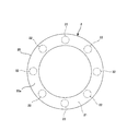
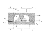
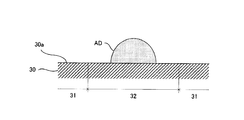
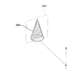
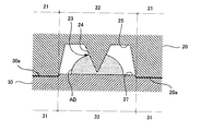
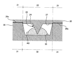
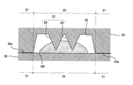
- FIG. 1 It is sectional drawing of an example of a lens apparatus for describing embodiment of this invention. It is a top view of the structural example of the adhesion location of the lens of the lens apparatus of FIG. 1, and a to-be-adhered member. It is sectional drawing of the adhesion location of FIG. It is a schematic diagram which shows the manufacturing method of the lens apparatus of FIG. It is a schematic diagram which shows the manufacturing method of the lens apparatus of FIG. It is a schematic diagram which shows the manufacturing method of the lens apparatus of FIG. It is a perspective view of an example of the projection provided in any one of the adhesion part of each of the lens and the to-be-adhered member which constitutes the adhesion part of Drawing 2, and is a perspective view showing the shape of one section.
- FIG. 5A It is a perspective view which shows the shape of the other cross section of the protrusion of FIG. 5A. It is sectional drawing of the protrusion of FIG. 5A and FIG. 5B. It is a perspective view of other examples of the projection provided in either one of the adhesion part of the lens which constitutes the adhesion location of Drawing 2, and a member to be adhered, and is a perspective view showing the shape of one section. It is a perspective view which shows the shape of the other cross section of the protrusion of FIG. 7A. It is a perspective view of the other example of the protrusion provided in the adhesion part of the lens which comprises the adhesion location of FIG.
- FIG. 1 It is a perspective view of the other example of the protrusion provided in the adhesion part of the lens which comprises the adhesion location of FIG. It is a top view of the other structural example of the adhesion location of the lens of the lens apparatus of FIG. 1, and a to-be-adhered member. It is sectional drawing of the other structural example of the adhesion location of the lens of the lens apparatus of FIG. 1, and a to-be-adhered member. It is sectional drawing of the other structural example of the adhesion location of the lens of the lens apparatus of FIG. 1, and a to-be-adhered member. It is sectional drawing of the other structural example of the adhesion location of the lens of the lens apparatus of FIG.
- FIG. 1 shows an example of a lens apparatus for explaining an embodiment of the present invention.
- the lens device 1 includes a lens 2 and a lens 3 as an adherend member.
- the lens 2 and the lens 3 are adjacent to each other in the axial direction of the optical axis X.
- the member to be bonded is a lens.
- the member to be bonded is not limited to a lens, and may be, for example, an interval ring interposed between the lens 2 and another lens, or the lens 2 is accommodated. It may be a mirror frame.
- the lens 2 is a substantially circular lens, and is a lens molded using a molding die using resin or glass as a material.
- an edge portion 20 that extends in a circular shape substantially perpendicular to the optical axis X is provided.
- the lens 3 is also a substantially circular lens, and is a lens formed using a molding die using resin or glass as a material.
- an edge portion 30 that extends in a circular shape substantially perpendicular to the optical axis X is provided.
- the surface 20a of the edge portion 20 of the lens 2 arranged to face the edge portion 30 of the lens 3 constitutes an area outside the optical effective diameter EA1 on the surface of the lens 2 including the surface 20a.
- the surface 30a of the edge portion 30 of the lens 3 arranged to face the edge portion 20 of the lens 2 constitutes an area outside the optical effective diameter EA2 on the surface of the lens 3 including the surface 30a.
- the “optically effective diameter” is defined by the surface of the lens in which the light beam contributing to image formation in the lens device 1 passes when passing through each lens.
- the lens 2 and the lens 3 are adhered to each other by an adhesive locally disposed between the surface 20a of the edge portion 20 and the surface 30a of the edge portion 30 that are disposed to face each other.
- FIG. 2 and FIG. 3 show an example of the configuration of the adhesion location between the lens 2 and the lens 3.
- a contact portion 21 and an adhesive portion 22 are provided on the surface 20 a of the edge portion 20 of the lens 2.
- a contact portion 31 and an adhesive portion 32 are provided on the surface 30 a of the edge portion 30 of the lens 3.
- a plurality of adhesive portions 22 of the lens 2 are provided at intervals in the circumferential direction of the lens 2.
- Each of the adhesive portions 22 has a convex portion 23 including a single protrusion 24, and each has a concave portion 25 surrounding the convex portion 23. is doing.
- the contact portion 21 of the lens 2 is formed by a region of the surface 20a of the edge portion 20 excluding the adhesive portion 22, and is formed on a plane substantially perpendicular to the optical axis X (see FIG. 1).
- a plurality of adhesive portions 32 of the lens 3 are provided at intervals in the circumferential direction of the lens 3, and are configured by a region disposed on the surface 30 a of the edge portion 30 so as to face the adhesive portion 22 of the lens 2.
- the contact portion 31 of the lens 3 is a region of the surface 30a of the edge portion 30 excluding the adhesive portion 32, and is configured by a region disposed to face the contact portion 21 of the lens 2, and has an optical axis. It is formed on a plane substantially perpendicular to X (see FIG. 1).
- the adhesive AD that bonds the lens 2 and the lens 3 is accommodated in the concave portion 25 of the adhesive portion 22 of the lens 2, and the tip portion of the protrusion 24 of the convex portion 23 surrounded by the concave portion 25 is immersed in the adhesive AD. ing.
- the adhesive AD adheres to the surface of the tip end portion of the protrusion 24 and the surface of the adhesive portion 32 of the lens 3 and adheres the lens 2 and the lens 3 to each other.
- the contact portion 21 of the lens 2 and the contact portion 31 of the lens 3 are in direct contact with each other in the axial direction of the optical axis X, whereby the lens 2 and the lens 3 are positioned relative to each other in the axial direction of the optical axis X. . Positioning accuracy of the lens 2 and the lens 3 is improved by the contact portion 21 and the contact portion 31 directly contacting each other without using the adhesive AD.
- the tip of the protrusion 24 may touch the surface of the adhesive portion 32 of the lens 3.
- the adhering adhesive AD may remain at the tip of the protrusion 24, and the adhesive AD remaining at the tip of the protrusion 24 is sandwiched between the surface of the adhesive portion 32 of the lens 3 and the contact portion 21 is applied. From the viewpoint of reliably preventing floating from the contact portion 31, it is desirable that a gap G is placed between the surface of the adhesive portion 32 of the lens 3 and the tip of the protrusion 24.
- the gap G is preferably 0.001 mm or more and 0.4 mm. It is as follows.
- the adhesive AD is applied to the adhesive portion 32 of the lens 3.
- the adhesive AD applied to the adhesive portion 32 is less than the volume of the concave portion 25 provided in the adhesive portion 22 of the lens 2.
- the lens 2 and the lens 3 are arranged in a state where the adhesive portion 22 of the lens 2 and the adhesive portion 32 of the lens 3 face each other. Then, as shown in FIG. 4C, the lens 2 and the lens 3 are overlapped, and the contact portion 21 of the lens 2 is abutted against the contact portion 31 of the lens 3.
- the adhesive AD applied to the adhesive portion 32 of the lens 3 is accommodated in the concave portion 25 of the adhesive portion 22 of the lens 2, and the tip portion of the protrusion 24 of the adhesive portion 22 is Cut into the adhesive AD.
- the adhesive AD is pushed away when the tip of the protrusion 24 bites in.
- the adhesive AD is less than the volume of the recess 25, the adhesive AD overflows from the recess 25 and contacts the contact portion 21 of the lens 2 and the lens 3. It does not reach between the contact portions 31 and remains inside the recess 25. Thereafter, the adhesive AD is cured, and the lens 2 and the lens 3 are bonded to each other.
- the viscosity at the start of the adhesive action of the adhesive AD that is, the tip of the protrusion 24 of the adhesive portion 22 of the lens 2 on the adhesive AD applied to the adhesive portion 32 of the lens 3 when the lens 2 and the lens 3 are overlapped.
- the viscosity at the time of contact is desirably high as long as the coating operation is not hindered, and is preferably 2000 mPa ⁇ s or more and 250,000 mPa ⁇ s or less.
- Adhesive AD is bonded to the adhesive AD by suppressing the dissipation of the adhesive AD due to the wetting and spreading of the adhesive AD and the inclination of the lens 3 before the start of the adhesive action due to the reasonably high viscosity of the adhesive AD. It can be kept on the part 32, and workability
- the protrusion 24 that immerses the tip in the adhesive AD is at least one of a cross section including the optical axis X and a cross section perpendicular to the radial direction centered on the optical axis X.
- the tip is formed in a tapered shape that is point-like and narrows toward the tip.
- the protrusion 24 Since the protrusion 24 has the above-described cross-sectional shape, the resistance when the tip portion of the protrusion 24 bites into the adhesive AD is reduced as compared with the case where the tip is formed in a flat shape, and the adhesive AD Even if the viscosity is relatively high, the tip end portion of the protrusion 24 can be smoothly sunk into the adhesive AD. Thereby, the contact part 21 of the lens 2 can be reliably abutted on the contact part 31 of the lens 3, and the positioning accuracy of the lens 2 and the lens 3 can be improved.
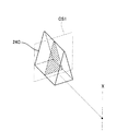
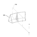
- FIG. 5A and FIG. 5B show an example of the protrusion 24.
- the protrusion 24A shown in FIGS. 5A and 5B is formed in a conical shape.
- the protrusion 24A has a triangular shape in a cross section CS1 perpendicular to the radial direction centered on the optical axis X, and has a tapered shape in which the tip is point-like and narrows toward the tip. Further, the protrusion 24A also has a triangular shape in the cross section CS2 including the optical axis X, and has a tapered shape in which the tip is dotted and narrows toward the tip.
- FIG. 6 shows the cross-sectional shape of the protrusion 24A shown in FIGS. 5A and 5B in detail.
- the lens 2 is a lens molded using resin or glass as a material using a molding die, and the protrusion 24A provided on the adhesive portion 22 of the lens 2 is also molded integrally with the lens 2 using the molding die. is there.
- molding die has a curvature. Therefore, “spot-like” with respect to the tip appearing in the cross section of the protrusion 24A includes a rounded shape having a curvature.
- the curvature radius r of the tip of the protrusion 24A is preferably 1 ⁇ m or more and 100 ⁇ m or less, more preferably, in a cross section where the tip appears in a dotted shape. Is from 5 ⁇ m to 70 ⁇ m, more preferably from 10 ⁇ m to 50 ⁇ m.
- the apex angle ⁇ of the tip of the protrusion 24A having a triangular shape in the cross section where the tip appears in a dotted shape is preferably 10 ° or more and 120. Or less, more preferably 20 ° or more and 100 ° or less, and further preferably 30 ° or more and 90 ° or less.
- the “vertical angle” of the tip of the projection 24A having a curvature is an angle formed by the tangent line T1 and the tangent line T2 at both ends of an arc having a radius of curvature r that forms the outline of the tip part.
- FIG. 7A and 7B show another example of the protrusion 24.
- FIG. 7A and 7B show another example of the protrusion 24.
- the protrusion 24B has a tapered shape in which the tip is point-like and narrows toward the tip in a cross section CS1 perpendicular to the radial direction centered on the optical axis X. Further, the protrusion 24B also has a tapered shape in which the tip is dotted and narrows toward the tip in the cross section CS2 including the optical axis X.
- the radius of curvature of the tip of the protrusion 24B is preferably 1 ⁇ m or more and 100 ⁇ m or less, more preferably, in the cross section where the tip appears in a dotted shape. They are 5 micrometers or more and 70 micrometers or less, More preferably, they are 10 micrometers or more and 50 micrometers or less.
- the protrusion 24 is not limited to the cone shape, and may be a column shape.
- the protrusion 24C shown in FIG. 8 is formed in a triangular prism shape, and is formed to extend in the radial direction around the optical axis X.
- the protrusion 24C has a triangular shape that is the same as the cross-sectional shape of the protrusion 24A shown in FIG. 5A in a cross section CS1 perpendicular to the radial direction centered on the optical axis X, and has a pointed tip and a taper that narrows toward the tip.
- the cross-sectional shape of the protrusion 24C is not limited to a triangular shape, and may be the same spindle shape as the cross-sectional shape of the protrusion 24B shown in FIG. 7A.
- the protrusion 24D shown in FIG. 9 is formed in a triangular prism shape and extends in the circumferential direction with the optical axis X as the center.
- the protrusion 24D has the same triangular shape as the cross section of the protrusion 24A illustrated in FIG. 5B, and has a tapered shape in which the tip is dotted and narrows toward the tip.
- the cross-sectional shape of the protrusion 24D is not limited to a triangular shape, and may be the same spindle shape as the cross-sectional shape of the protrusion 24B shown in FIG. 7B.
- the projection 24 when the projection 24 is formed to extend in the circumferential direction around the optical axis X as in the projection 24D shown in FIG. 9, as shown in FIG. It can also be provided in an annular shape over the entire circumference of the edge portion 20.
- FIG. 11 shows another configuration example of a bonding portion between the lens 2 and the lens 3.
- a concave portion 35 is provided in the adhesive portion 32 of the lens 3 as a concave portion that surrounds the periphery of the convex portion 23 provided in the adhesive portion 22 of the lens 2 and accommodates the adhesive AD.
- an adhesive AD less than the volume of the recess 35 is applied to the bottom of the recess 35, and the lens 2 and the lens 3 are overlapped and bonded to each other.
- the application position of the adhesive AD is clearly indicated by the concave portion 35 provided in the adhesive portion 32 of the lens 3, and further, dissipation of the adhesive AD applied to the concave portion 35 is further suppressed, so that workability is improved.
- FIG. 12 shows another configuration example of a bonding portion between the lens 2 and the lens 3.
- the first concave portion 26 is provided in the adhesive portion 22 of the lens 2
- the second concave portion 36 is provided in the adhesive portion 32 of the lens 3.
- a concave portion that surrounds the periphery of the convex portion 23 provided in the adhesive portion 22 of the lens 2 and accommodates the adhesive AD is configured.
- an adhesive AD less than the total volume of the first recess 26 and the second recess 36 is applied to the bottom of the second recess 36, and the lens 2 and the lens 3 are overlapped and bonded to each other.
- the application position of the adhesive AD is clearly indicated by the second concave portion 36 provided in the adhesive portion 32 of the lens 3, and furthermore, dissipation of the adhesive AD applied to the second concave portion 36 is further suppressed, so that workability is improved. Rise.
- FIG. 13 and FIG. 14 show other examples of the structure of the adhesion between the lens 2 and the lens 3, respectively.
- the fitting convex portion 37 that fits into the concave portion 25 provided in the bonding portion 22 of the lens 2 is formed in the lens 3. This is further provided in the adhesive portion 32.
- the lens 2 and the lens 3 are arranged in a state where the adhesive portion 22 of the lens 2 and the adhesive portion 32 of the lens 3 face each other and overlap each other. At this time, the concave portion 25 and the fitting convex portion 37 This facilitates the positioning of the lens 2 and the lens 3 and improves workability.
- the lens 2 and the lens 3 can be easily positioned by fitting the concave portion 35 and the fitting convex portion 27, and the workability is improved.
- the convex portion 23 provided on the adhesive portion 22 of the lens 2 has been described as being configured by one protrusion 24.
- the convex portion 23 is centered on the optical axis X. It may be constituted by a plurality of protrusions 24 arranged in multiple rows in the radial direction.
- the tips of the protrusions 24 are immersed in the adhesive AD, and the adhesive AD adheres to the surfaces of the tips of the protrusions 24 and the surface of the bonding portion 32 of the lens 3 to bond the lens 2 and the lens 3 to each other. To do. Thereby, the adhesive strength between the lens 2 and the lens 3 is increased.
- the lens device disclosed in the present specification is a lens device including a lens and an adherend member that is adjacent to the lens in the optical axis direction of the lens and to which the lens is bonded.
- the lens and the member to be bonded are in contact with each other in the optical axis direction in a region outside the optically effective diameter of the lens on each facing surface, and in the circumferential direction of the lens.
- One of the bonding portions of the bonding member is provided with a convex portion including one or more protrusions, and at least one of the bonding portions of the lens and the member to be bonded is provided.
- the adhesive part is provided with a concave part surrounding the convex part and containing the adhesive, and the protrusion has a cross section including the optical axis of the lens and the optical axis of the lens as a center.
- the tip is formed in a tapered shape having a dot shape and narrowing toward the tip, and at least the tip portion of the protrusion is accommodated in the recess.
- the adhesive is immersed in the adhesive, and the adhesive is bonded to the other of the adhesive portions of the lens and the member to be bonded, which is opposite to the one of the adhesive portions provided with the convex portion. It adheres to the surface of the part and the surface of the protrusion.
- the curvature radius of the tip of the projection is 1 ⁇ m or more and 100 ⁇ m or less in the cross section where the tip of the projection appears in a dot shape.
- the protrusion in the cross section in which the tip of the protrusion appears in a dotted shape, the protrusion has a triangular shape, and the apex angle of the tip of the protrusion is not less than 10 ° and not more than 120 °. is there.
- the lens device disclosed in the present specification is configured such that, of the adhesion portions of the lens and the adherend member, the other adhesion portion on the opposite side to the one adhesion portion where the convex portion is provided.
- the gap between the surface and the tip of the protrusion is 0.001 mm or more and 0.4 mm or less.
- the convex portion includes a plurality of the protrusions, and the plurality of protrusions are provided in a double row in a radial direction centered on the optical axis of the lens. ing.
- the lens device disclosed in the present specification is such that at least one of the bonding portions of the lens and the member to be bonded is bonded to the other side opposite to the one bonding portion provided with the convex portion.
- the recess is provided in the part.
- the concave portion is provided only in one of the bonding portions of the lens and the bonded member, and the concave portion is provided in the other bonding portion.
- the fitting convex part fitted to is provided.
- the other of the bonding portions on the side opposite to the bonding portion provided with the convex portion is disposed on the bonding portion, and the lens and the member to be bonded are overlapped in the optical axis direction of the lens to bond the lens and the member to be bonded.
- the other of the bonding portions on the side opposite to the bonding portion provided with the convex portion is disposed on the adhesive portion.
- the viscosity at the start of the adhesive action of the adhesive is 2000 mPa ⁇ s or more and 250,000 mPa ⁇ s or less.
- the present invention can be used for a lens device of an optical device such as a camera mounted on a portable terminal such as an in-vehicle camera or a smartphone, an optical pickup, and a manufacturing method thereof.
- Lens device 2 Lens 3 Lens (Adhered member) 20 Edge 20a Surface 21 Abutment 22 Adhesive 23 Protrusion 24 Protrusion 24A Protrusion 24B Protrusion 24C Protrusion 24D Protrusion 25 Concavity 26 First Concavity 27 Fitting Convex 30 Edge 30A Surface 31 Abutment 32 Adhesion 35 Concavity 36 2nd recessed part 37 Fitting convex part AD Adhesive CS1 Section CS2 Section EA1 Optical effective diameter EA2 Optical effective diameter r Curvature radius T1 Tangent T2 Tangent X Optical axis ⁇ Vertical angle
Landscapes
- Physics & Mathematics (AREA)
- General Physics & Mathematics (AREA)
- Optics & Photonics (AREA)
- Lens Barrels (AREA)
Abstract
レンズ装置1のレンズ2及びレンズ3は、光軸方向に互いに直接当接した当接部と、レンズの周方向に間隔をあけて設けられた複数の接着部をそれぞれ有し、レンズ2の接着部22には、突起24を含む凸部23が設けられ、凸部23の周囲を囲む凹部25であって接着剤ADを収容した凹部25が設けられており、突起24は、先端が点状であり且つ先端に向かって細くなるテーパ状の断面形状に形成されており、突起24の先端部は、凹部25に収容された接着剤ADに没入しており、接着剤ADは、レンズ3の接着部32の表面と、突起24の表面と、に付着している。
Description
本発明は、レンズ装置及びレンズ装置の製造方法に関する。
車載カメラ、スマートフォンなどの携帯端末に搭載されるカメラ、光ピックアップ等の光学機器に用いられるレンズ装置では、レンズが、他のレンズと接着され、若しくは他のレンズとの間に介在する間隔環と接着され、又はレンズを収納する鏡枠と接着されて固定されている。
特許文献1に記載された走査光学装置では、シリンダレンズが枠体に接着されている。シリンダレンズが設置される枠体の座面には、座面に対して凹となる接着面が設けられている。シリンダレンズには、枠体の座面に直接に突き当てられる基準面と、枠体の接着面と対向して配置される接着面とが設けられており、基準面及び接着面はシリンダレンズの下面に対して凸となっている。
枠体の接着面に接着剤が塗布された状態で、シリンダレンズの基準面が枠体の座面に突き当てられ、シリンダレンズの接着面が枠体の接着面に塗布された接着剤に接触する。接着剤が塗布された枠体の接着面は座面に対して凹となっており、接着剤は、座面には及ばず、シリンダレンズの接着面と枠体の接着面との間にとどまる。シリンダレンズの基準面と枠体の座面とが接着剤を介することなく直接当接し、シリンダレンズが位置決めされる。
特許文献2に記載されたレンズユニットでは、レンズがレンズ枠に接着されている。レンズが設置されるレンズ枠の受け部には、溝部を有する接着面が設けられており、溝部には、周囲のバッファ部に対して凸となる中間部が設けられている。レンズには、レンズ枠の溝を含む接着面に対向して配置される平面部が設けられている。
レンズ枠の溝部の中間部に接着剤が塗布された状態で、レンズの平面部が、レンズ枠の接着面に突き当てられ、レンズ枠の溝部の中間部に配置された接着剤に接触する。接着剤が塗布されたレンズ枠の溝部の中間部は周囲のバッファ部に対して凸となっており、接着剤は、レンズ枠の接着面には及ばず、レンズ枠の溝部にとどまる。レンズの平面部とレンズ枠の接着面とが接着剤を介することなく直接当接し、レンズが位置決めされる。
レンズと被接着部材(他のレンズ若しくは間隔環、又は鏡枠)とを接着する接着剤の粘度は塗布作業に支障がない範囲で高いことが望ましい。接着剤の粘度が適度に高いことにより、レンズ及び被接着部材の一方に塗布された接着剤がレンズ及び被接着部材の他方と接触するまでの間に、例えば塗布面上での濡れ広がり、また塗布面の傾き等に起因して接着剤が散逸することを抑制でき、作業性を高めることができる。
特許文献1に記載された走査光学装置では、シリンダレンズの接着面は平面状であり、シリンダレンズの接着面が枠体の接着面に塗布された接着剤に沈み込んでシリンダレンズの接着面と接着剤とが接触する。この場合に、接着剤の粘度が高いと、接着剤の粘性抵抗に起因して、シリンダレンズの接着面の接着剤への沈み込みが不足する虞がある。そして、シリンダレンズの接着面の接着剤への沈み込みが不足すると、シリンダレンズの基準面が枠体の座面から浮いてしまい、シリンダレンズの位置決め精度が低下する虞がある。一方、接着剤の粘度が低いと、シリンダレンズの接着面との接触以前に接着剤が濡れ広がって散逸する虞があり、その結果、シリンダレンズと枠体との接着が不十分となる虞がある。
特許文献2に記載されたレンズユニットもまた、レンズ枠の溝部の中間部は平面状であり、レンズ枠の溝部の中間部がこの中間部に塗布された接着剤に沈み込んでレンズの平面部と接着剤とが接触する。この場合に、接着剤の粘度が高いと、接着剤の粘性抵抗に起因して、レンズ枠の溝部の中間部の接着剤への沈み込みが不足する虞がある。そして、レンズ枠の溝部の中間部の接着剤への沈み込みが不足すると、レンズの平面部がレンズ枠の接着面から浮いてしまい、レンズの位置決め精度が低下する虞がある。一方、接着剤の粘度が低いと、レンズの平面部との接触以前に接着剤が濡れ広がって散逸する虞があり、その結果、レンズとレンズ枠との接着が不十分となる虞がある。
本発明は、上述した事情に鑑みなされたものであり、レンズと被接着部材との接着を確実に行うことができ、レンズと被接着部材の位置決め精度を高めることができるレンズ装置及びレンズ装置の製造方法を提供することを目的としている。
本発明の一態様のレンズ装置は、レンズと、上記レンズの光軸方向に上記レンズと隣設され上記レンズが接着される被接着部材と、を備えるレンズ装置であって、上記レンズ及び上記被接着部材は、それぞれの対向面における上記レンズの光学的有効径よりも外側の領域に、上記光軸方向に互いに直接当接した当接部と、上記レンズの周方向に間隔をあけて設けられた複数の接着部又は全周に亘って設けられた環状の接着部であって接着剤を介して互いに接着された接着部と、をそれぞれ有し、上記レンズ及び上記被接着部材それぞれの上記接着部のうち一方の上記接着部には、一つ以上の突起を含む凸部が設けられており、また、上記レンズ及び上記被接着部材それぞれの上記接着部のうち少なくとも一方の上記接着部には、上記凸部の周囲を囲む凹部であって上記接着剤を収容した凹部が設けられており、上記突起は、上記レンズの光軸を含む断面及び上記レンズの光軸を中心とする放射方向に垂直な断面のうち少なくとも一方の断面において、先端が点状であり且つ先端に向かって細くなるテーパ状にそれぞれ形成されており、上記突起の少なくとも先端部は、上記凹部に収容された上記接着剤に没入しており、上記接着剤は、上記レンズ及び上記被接着部材それぞれの上記接着部のうち上記凸部が設けられた一方の上記接着部とは反対側の他方の上記接着部の表面と、上記突起の表面と、に付着している
また、本発明の一態様のレンズ装置の製造方法は、上記レンズ及び上記被接着部材それぞれの上記接着部のうち、上記凸部が設けられた一方の上記接着部とは反対側の他方の上記接着部に上記接着剤を配置し、上記レンズ及び上記被接着部材を上記レンズの光軸方向に重ね合わせて、上記レンズ及び上記被接着部材を接着する。
本発明によれば、レンズと被接着部材との接着を確実に行うことができ、レンズと被接着部材の位置決め精度を高めることができる。
図1は、本発明の実施形態を説明するための、レンズ装置の一例を示す。
レンズ装置1は、レンズ2と、被接着部材としてのレンズ3とを備える。レンズ2とレンズ3とは、光軸Xの軸方向に隣設されている。なお、本例では被接着部材がレンズであるが、被接着部材はレンズに限られず、例えばレンズ2と他のレンズとの間に介在する間隔環であってもよいし、レンズ2を収納する鏡枠であってもよい。
レンズ2は、略円形状のレンズであり、樹脂又はガラスを材料として成形型を用いて成形されたレンズである。レンズ2の外周部には、光軸Xに対して略垂直に円状に広がるコバ部20が設けられている。レンズ3もまた、略円形状のレンズであり、樹脂又はガラスを材料として成形型を用いて成形されたレンズである。レンズ3の外周部には、光軸Xに対して略垂直に円状に広がるコバ部30が設けられている。
レンズ3のコバ部30に対向して配置されるレンズ2のコバ部20の表面20aは、この表面20aを含むレンズ2の表面における光学的有効径EA1よりも外側の領域を構成している。同様に、レンズ2のコバ部20に対向して配置されるレンズ3のコバ部30の表面30aは、この表面30aを含むレンズ3の表面における光学的有効径EA2よりも外側の領域を構成している。なお、「光学的有効径」とは、レンズ装置1において結像に寄与する光線が各レンズを通過する際に通る領域をレンズの表面にて規定したものである。
互いに対向して配置されたコバ部20の表面20aとコバ部30の表面30aとの間に局所的に配置された接着剤によって、レンズ2とレンズ3とは互いに接着されている。
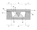
図2及び図3は、レンズ2とレンズ3との接着箇所の構成例を示す。
レンズ2のコバ部20の表面20aには、当接部21と、接着部22とが設けられている。また、レンズ3のコバ部30の表面30aには、当接部31と、接着部32とが設けられている。
レンズ2の接着部22は、レンズ2の周方向に間隔をあけて複数設けられ、一つの突起24からなる凸部23をそれぞれ有し、さらに、凸部23の周囲を囲む凹部25をそれぞれ有している。レンズ2の当接部21は、コバ部20の表面20aのうち接着部22を除いた領域によって構成されており、光軸X(図1参照)に略垂直な平面に形成されている。
レンズ3の接着部32は、レンズ3の周方向に間隔をあけて複数設けられ、コバ部30の表面30aのうちレンズ2の接着部22と対向して配置される領域によって構成されている。レンズ3の当接部31は、コバ部30の表面30aのうち、接着部32を除いた領域であって、レンズ2の当接部21と対向して配置される領域によって構成され、光軸X(図1参照)に略垂直な平面に形成されている。
レンズ2とレンズ3とを接着する接着剤ADはレンズ2の接着部22の凹部25に収容されており、凹部25によって囲まれた凸部23の突起24の先端部は接着剤ADに没入している。接着剤ADは、突起24の先端部の表面、及びレンズ3の接着部32の表面に付着し、レンズ2とレンズ3とを互いに接着している。
レンズ2の当接部21とレンズ3の当接部31とは光軸Xの軸方向に互いに直接当接して、これによりレンズ2及びレンズ3は光軸Xの軸方向に互いに位置決めされている。当接部21と当接部31とが接着剤ADを介することなく直接当接することにより、レンズ2及びレンズ3の位置決め精度が高められる。
レンズ2の当接部21とレンズ3の当接部31とが直接当接した状態で、突起24の先端がレンズ3の接着部32の表面に触れていてもよいが、突起24の先端に付着した接着剤ADが突起24の先端に残留する可能性もあり、突起24の先端に残留した接着剤ADがレンズ3の接着部32の表面との間に挟まれて当接部21が当接部31から浮くことを確実に防止する観点から、レンズ3の接着部32の表面と突起24の先端との間に隙間Gが置かれていることが望ましい。ただし、隙間Gが過大であると接着剤ADと突起24の先端部との接触面積が小さくなって接着強度が不足する可能性があるため、隙間Gは、好ましくは0.001mm以上0.4mm以下である。
図4Aから図4Cは、レンズ2とレンズ3との接着工程を順に示す。
まず、図4Aに示すように、レンズ3の接着部32に接着剤ADがそれぞれ塗布される。接着部32に塗布される接着剤ADは、レンズ2の接着部22に設けられた凹部25の容積未満とされる。
次に、図4Bに示すように、レンズ2の接着部22とレンズ3の接着部32とが互いに対向した状態にレンズ2とレンズ3とが配置される。そして、図4Cに示すように、レンズ2とレンズ3とが重ね合され、レンズ2の当接部21がレンズ3の当接部31に突き当てられる。
レンズ2とレンズ3との重ね合せに伴い、レンズ3の接着部32に塗布された接着剤ADは、レンズ2の接着部22の凹部25に収容され、接着部22の突起24の先端部が接着剤ADに食い込む。突起24の先端部が食い込むことによって接着剤ADは周囲に押し退けられるが、接着剤ADは凹部25の容積未満であることから、凹部25から溢れてレンズ2の当接部21とレンズ3の当接部31との間に及ぶことはなく、凹部25の内部にとどまる。その後、接着剤ADが硬化され、レンズ2とレンズ3とが互いに接着される。
接着剤ADの接着行為の開始時における粘度、即ち、レンズ2とレンズ3との重ね合せに伴いレンズ3の接着部32に塗布された接着剤ADにレンズ2の接着部22の突起24の先端が接触する時の粘度は、塗布作業に支障がない範囲で高いことが望ましく、好ましくは2000mPa・s以上250000mPa・s以下である。接着剤ADの粘度が適度に高いことにより、接着行為の開始以前に接着剤ADの濡れ広がり、レンズ3の傾き等に起因して接着剤ADが散逸することを抑制して接着剤ADを接着部32に留め置くことができ、作業性を高めることができる。
レンズ2とレンズ3との重ね合せに伴って先端部を接着剤ADに没入させる突起24は、光軸Xを含む断面及び光軸Xを中心とする放射方向に垂直な断面のうち少なくとも一方の断面において、先端が点状であり且つ先端に向かって細くなるテーパ状に形成されている。
突起24が上記の断面形状を有していることにより、先端が平面状に形成されている場合に比べて、突起24の先端部が接着剤ADに食い込む際の抵抗が低減され、接着剤ADの粘度が比較的高くとも突起24の先端部を接着剤ADに円滑に食い込ませることができる。これにより、レンズ2の当接部21をレンズ3の当接部31に確実に突き当てることができ、レンズ2及びレンズ3の位置決め精度を高められる。
図5A及び図5Bは、突起24の一例を示す。
図5A及び図5Bに示す突起24Aは円錐状に形成されている。突起24Aは、光軸Xを中心とする放射方向に垂直な断面CS1において、三角形状を呈し、先端が点状で且つ先端に向かって細くなるテーパ状を呈する。また、突起24Aは、光軸Xを含む断面CS2においても、三角形状を呈し、先端が点状で且つ先端に向かって細くなるテーパ状を呈する。
図6は、図5A及び図5Bに示した突起24Aの断面形状を詳細に示す。
レンズ2は樹脂又はガラスを材料として成形型を用いて成形されたレンズであり、レンズ2の接着部22に設けられる突起24Aもまた、成形型を用いてレンズ2と一体に成形されたものである。一般に、成形型を用いて成形された成形体のエッジは曲率を有する。したがって、突起24Aの断面に表れる先端に関して「点状」であるとは、曲率を有し、丸みを帯びたものも含むものである。
突起24Aの先端部が接着剤ADに食い込む際の抵抗を低減する観点から、先端が点状に表れる断面において、突起24Aの先端の曲率半径rは、好ましくは1μm以上100μm以下であり、より好ましくは5μm以上70μm以下であり、さらに好ましくは10μm以上50μm以下である。
また、突起24Aの先端部が接着剤ADに食い込む際の抵抗を低減する観点から、先端が点状に表れる断面において三角形状を呈する突起24Aの先端の頂角θは、好ましくは10°以上120°以下であり、より好ましくは20°以上100°以下であり、さらに好ましくは30°以上90°以下である。なお、曲率を有する突起24Aの先端の「頂角」は、先端部の輪郭を形成する曲率半径rの円弧の両端の接線T1及び接線T2によって形成される角とする。
図7A及び図7Bは、突起24の他の例を示す。
図7A及び図7Bに示す突起24Bは紡錘状に形成されている。突起24Bは、光軸Xを中心とする放射方向に垂直な断面CS1において、先端が点状で且つ先端に向かって細くなるテーパ状を呈する。また、突起24Bは、光軸Xを含む断面CS2においても、先端が点状で且つ先端に向かって細くなるテーパ状を呈する。
突起24Bの先端部が接着剤ADに食い込む際の抵抗を低減する観点から、先端が点状に表れる断面において、突起24Bの先端の曲率半径は、好ましくは1μm以上100μm以下であり、より好ましくは5μm以上70μm以下であり、さらに好ましくは10μm以上50μm以下である。
また、突起24は、錐状に限られず、柱状であってもよい。
図8に示す突起24Cは、三角柱状に形成されており、且つ光軸Xを中心とする放射方向に延びて形成されている。突起24Cは、光軸Xを中心とする放射方向に垂直な断面CS1において、図5Aに示した突起24Aの断面形状と同じ三角形状を呈し、先端が点状で且つ先端に向かって細くなるテーパ状を呈する。なお、突起24Cの断面形状は、三角形状に限られず、図7Aに示した突起24Bの断面形状と同じ紡錘形状であってもよい。
図9に示す突起24Dは、三角柱状に形成されており、且つ光軸Xを中心とする円周方向に延びて形成されている。突起24Dは、光軸Xを含む断面CS2において、図5Bに示した突起24Aの断面形状と同じ三角形状を呈し、先端が点状で且つ先端に向かって細くなるテーパ状を呈する。なお、突起24Dの断面形状は、三角形状に限られず、図7Bに示した突起24Bの断面形状と同じ紡錘形状であってもよい。
また、図9に示した突起24Dのように、突起24が光軸Xを中心とする円周方向に延びて形成される場合に、図10に示すように、レンズ2の接着部22を、コバ部20の全周に亘って円環状に設けることもできる。
図11は、レンズ2とレンズ3との接着箇所の他の構成例を示す。
図11に示す例では、レンズ2の接着部22に設けられた凸部23の周囲を囲み、且つ接着剤ADを収容する凹部として、レンズ3の接着部32に凹部35が設けられている。本例では、凹部35の容積未満の接着剤ADが凹部35の底に塗布され、レンズ2とレンズ3とが重ね合されて互いに接着される。レンズ3の接着部32に設けられた凹部35によって接着剤ADの塗布位置が明示され、さらに、凹部35に塗布された接着剤ADは散逸が一層抑制されるので、作業性が高まる。
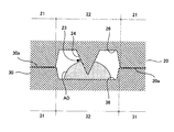
図12は、レンズ2とレンズ3との接着箇所の他の構成例を示す。
図12に示す例では、レンズ2の接着部22に第1凹部26が設けられ、レンズ3の接着部32に第2凹部36が設けられており、これら第1凹部26及び第2凹部36によって、レンズ2の接着部22に設けられた凸部23の周囲を囲み、且つ接着剤ADを収容する凹部が構成されている。本例では、第1凹部26及び第2凹部36の合計の容積未満の接着剤ADが第2凹部36の底に塗布され、レンズ2とレンズ3とが重ね合されて互いに接着される。レンズ3の接着部32に設けられた第2凹部36によって接着剤ADの塗布位置が明示され、さらに、第2凹部36に塗布された接着剤ADは散逸が一層抑制されるので、作業性が高まる。
図13及び図14は、レンズ2とレンズ3との接着箇所の他の構成例をそれぞれ示す。
図13に示す例は、図3に示したレンズ2とレンズ3との接着箇所の構成例において、レンズ2の接着部22に設けられた凹部25に嵌合する嵌合凸部37をレンズ3の接着部32にさらに設けたものである。レンズ2の接着部22とレンズ3の接着部32とが互いに対向した状態にレンズ2とレンズ3とが配置されて互いに重ね合されるが、その際に、凹部25と嵌合凸部37との嵌合によってレンズ2及びレンズ3の位置決めが容易となり、作業性が高まる。
図14に示す例は、図11に示したレンズ2とレンズ3との接着箇所の構成例において、レンズ3の接着部32に設けられた凹部35に嵌合する嵌合凸部27をレンズ2の接着部22にさらに設けたものであり、図13に示した例と同様、凹部35と嵌合凸部27との嵌合によってレンズ2及びレンズ3の位置決めが容易となり、作業性が高まる。
ここまで、レンズ2の接着部22に設けられた凸部23が一つの突起24によって構成されているものとして説明したが、図15に示すように、凸部23は、光軸Xを中心とする放射方向に複列に並ぶ複数の突起24によって構成されてもよい。突起24それぞれの先端部が接着剤ADに没入し、接着剤ADは、突起24それぞれの先端部の表面、及びレンズ3の接着部32の表面に付着し、レンズ2とレンズ3とを互いに接着する。これによりレンズ2とレンズ3との接着強度が高まる。
以上説明したとおり、本明細書に開示されたレンズ装置は、レンズと、上記レンズの光軸方向に上記レンズと隣設され上記レンズが接着される被接着部材と、を備えるレンズ装置であって、上記レンズ及び上記被接着部材は、それぞれの対向面における上記レンズの光学的有効径よりも外側の領域に、上記光軸方向に互いに直接当接した当接部と、上記レンズの周方向に間隔をあけて設けられた複数の接着部又は全周に亘って設けられた環状の接着部であって接着剤を介して互いに接着された接着部と、をそれぞれ有し、上記レンズ及び上記被接着部材それぞれの上記接着部のうち一方の上記接着部には、一つ以上の突起を含む凸部が設けられており、また、上記レンズ及び上記被接着部材それぞれの上記接着部のうち少なくとも一方の上記接着部には、上記凸部の周囲を囲む凹部であって上記接着剤を収容した凹部が設けられており、上記突起は、上記レンズの光軸を含む断面及び上記レンズの光軸を中心とする放射方向に垂直な断面のうち少なくとも一方の断面において、先端が点状であり且つ先端に向かって細くなるテーパ状にそれぞれ形成されており、上記突起の少なくとも先端部は、上記凹部に収容された上記接着剤に没入しており、上記接着剤は、上記レンズ及び上記被接着部材それぞれの上記接着部のうち上記凸部が設けられた一方の上記接着部とは反対側の他方の上記接着部の表面と、上記突起の表面と、に付着している。
また、本明細書に開示されたレンズ装置は、上記突起の先端が点状に表れる上記断面において、上記突起の先端の曲率半径は1μm以上100μm以下である。
また、本明細書に開示されたレンズ装置は、上記突起の先端が点状に表れる上記断面において、上記突起は三角形状であり、且つ上記突起の先端の頂角は10°以上120°以下である。
また、本明細書に開示されたレンズ装置は、上記レンズ及び上記被接着部材それぞれの上記接着部のうち上記凸部が設けられた一方の上記接着部とは反対側の他方の上記接着部の表面と、上記突起の先端との隙間は0.001mm以上0.4mm以下である。
また、本明細書に開示されたレンズ装置は、上記凸部は、複数の上記突起を含み、複数の上記突起は、上記レンズの光軸を中心とする放射方向に複列に並んで設けられている。
また、本明細書に開示されたレンズ装置は、上記レンズ及び上記被接着部材それぞれの上記接着部のうち、少なくとも、上記凸部が設けられた一方の上記接着部とは反対側の他方の接着部に上記凹部が設けられている。
また、本明細書に開示されたレンズ装置は、上記レンズ及び上記被接着部材それぞれの上記接着部のうち、一方の上記接着部にのみ上記凹部が設けられ、他方の上記接着部には上記凹部に嵌合した嵌合凸部が設けられている。
また、本明細書に開示されたレンズ装置の製造方法は、上記レンズ及び上記被接着部材それぞれの上記接着部のうち、上記凸部が設けられた一方の上記接着部とは反対側の他方の上記接着部に上記接着剤を配置し、上記レンズ及び上記被接着部材を上記レンズの光軸方向に重ね合わせて、上記レンズ及び上記被接着部材を接着する。
また、本明細書に開示されたレンズ装置の製造方法は、上記レンズ及び上記被接着部材それぞれの上記接着部のうち、上記凸部が設けられた一方の上記接着部とは反対側の他方の上記接着部に、上記凸部の周囲を囲む上記凹部の容積未満の上記接着剤を配置する。
また、本明細書に開示されたレンズ装置の製造方法は、上記接着剤の接着行為の開始時における粘度は、2000mPa・s以上250000mPa・s以下である。
本発明は、車載カメラ、スマートフォンなどの携帯端末に搭載されるカメラ、光ピックアップ等の光学機器のレンズ装置及びその製造方法に用いることができる。
以上本発明の実施形態を詳述したがこれはあくまで一例示であり、本発明はその趣旨を逸脱しない範囲において種々変更を加えた態様で実施可能である。本出願は、2016年3月30日出願の日本特許出願(特願2016-068464)に基づくものであり、その内容はここに参照として取り込まれる。
1 レンズ装置
2 レンズ
3 レンズ(被接着部材)
20 コバ部
20a 表面
21 当接部
22 接着部
23 凸部
24 突起
24A 突起
24B 突起
24C 突起
24D 突起
25 凹部
26 第1凹部
27 嵌合凸部
30 コバ部
30a 表面
31 当接部
32 接着部
35 凹部
36 第2凹部
37 嵌合凸部
AD 接着剤
CS1 断面
CS2 断面
EA1 光学的有効径
EA2 光学的有効径
r 曲率半径
T1 接線
T2 接線
X 光軸
θ 頂角
2 レンズ
3 レンズ(被接着部材)
20 コバ部
20a 表面
21 当接部
22 接着部
23 凸部
24 突起
24A 突起
24B 突起
24C 突起
24D 突起
25 凹部
26 第1凹部
27 嵌合凸部
30 コバ部
30a 表面
31 当接部
32 接着部
35 凹部
36 第2凹部
37 嵌合凸部
AD 接着剤
CS1 断面
CS2 断面
EA1 光学的有効径
EA2 光学的有効径
r 曲率半径
T1 接線
T2 接線
X 光軸
θ 頂角
Claims (10)
- レンズと、前記レンズの光軸方向に前記レンズと隣設され前記レンズが接着される被接着部材と、を備えるレンズ装置であって、
前記レンズ及び前記被接着部材は、それぞれの対向面における前記レンズの光学的有効径よりも外側の領域に、前記光軸方向に互いに直接当接した当接部と、前記レンズの周方向に間隔をあけて設けられた複数の接着部又は全周に亘って設けられた環状の接着部であって接着剤を介して互いに接着された接着部と、をそれぞれ有し、
前記レンズ及び前記被接着部材それぞれの前記接着部のうち一方の前記接着部には、一つ以上の突起を含む凸部が設けられており、
また、前記レンズ及び前記被接着部材それぞれの前記接着部のうち少なくとも一方の前記接着部には、前記凸部の周囲を囲む凹部であって前記接着剤を収容した凹部が設けられており、
前記突起は、前記レンズの光軸を含む断面及び前記レンズの光軸を中心とする放射方向に垂直な断面のうち少なくとも一方の断面において、先端が点状であり且つ先端に向かって細くなるテーパ状にそれぞれ形成されており、
前記突起の少なくとも先端部は、前記凹部に収容された前記接着剤に没入しており、
前記接着剤は、前記レンズ及び前記被接着部材それぞれの前記接着部のうち前記凸部が設けられた一方の前記接着部とは反対側の他方の前記接着部の表面と、前記突起の表面と、に付着しているレンズ装置。 - 請求項1記載のレンズ装置であって、
前記突起の先端が点状に表れる前記断面において、前記突起の先端の曲率半径は1μm以上100μm以下であるレンズ装置。 - 請求項2記載のレンズ装置であって、
前記突起の先端が点状に表れる前記断面において、前記突起は三角形状であり、且つ前記突起の先端の頂角は10°以上120°以下であるレンズ装置。 - 請求項1から3のいずれか一項記載のレンズ装置であって、
前記レンズ及び前記被接着部材それぞれの前記接着部のうち前記凸部が設けられた一方の前記接着部とは反対側の他方の前記接着部の表面と、前記突起の先端との隙間は0.001mm以上0.4mm以下であるレンズ装置。 - 請求項1から4のいずれか一項記載のレンズ装置であって、
前記凸部は、複数の前記突起を含み、
複数の前記突起は、前記レンズの光軸を中心とする放射方向に複列に並んで設けられているレンズ装置。 - 請求項1から5のいずれか一項記載のレンズ装置であって、
前記レンズ及び前記被接着部材それぞれの前記接着部のうち、少なくとも、前記凸部が設けられた一方の前記接着部とは反対側の他方の接着部に前記凹部が設けられているレンズ装置。 - 請求項1から6のいずれか一項記載のレンズ装置であって、
前記レンズ及び前記被接着部材それぞれの前記接着部のうち、一方の前記接着部にのみ前記凹部が設けられ、他方の前記接着部には前記凹部に嵌合した嵌合凸部が設けられているレンズ装置。 - 請求項1から7のいずれか一項記載のレンズ装置の製造方法であって、
前記レンズ及び前記被接着部材それぞれの前記接着部のうち、前記凸部が設けられた一方の前記接着部とは反対側の他方の前記接着部に前記接着剤を配置し、
前記レンズ及び前記被接着部材を前記レンズの光軸方向に重ね合わせて、前記レンズ及び前記被接着部材を接着するレンズ装置の製造方法。 - 請求項8記載のレンズ装置の製造方法であって、
前記レンズ及び前記被接着部材それぞれの前記接着部のうち、前記凸部が設けられた一方の前記接着部とは反対側の他方の前記接着部に、前記凸部の周囲を囲む前記凹部の容積未満の前記接着剤を配置するレンズ装置の製造方法。 - 請求項8又は9記載のレンズ装置の製造方法であって、
前記接着剤の接着行為の開始時における粘度は、2000mPa・s以上250000mPa・s以下であるレンズ装置の製造方法。
Applications Claiming Priority (2)
| Application Number | Priority Date | Filing Date | Title |
|---|---|---|---|
| JP2016-068464 | 2016-03-30 | ||
| JP2016068464 | 2016-03-30 |
Publications (1)
| Publication Number | Publication Date |
|---|---|
| WO2017168938A1 true WO2017168938A1 (ja) | 2017-10-05 |
Family
ID=59964112
Family Applications (1)
| Application Number | Title | Priority Date | Filing Date |
|---|---|---|---|
| PCT/JP2017/000865 Ceased WO2017168938A1 (ja) | 2016-03-30 | 2017-01-12 | レンズ装置及びレンズ装置の製造方法 |
Country Status (1)
| Country | Link |
|---|---|
| WO (1) | WO2017168938A1 (ja) |
Cited By (1)
| Publication number | Priority date | Publication date | Assignee | Title |
|---|---|---|---|---|
| JP2023078735A (ja) * | 2021-11-26 | 2023-06-07 | キヤノン株式会社 | 光学素子、光学機器、撮像装置、及び光学素子の製造方法 |
Citations (2)
| Publication number | Priority date | Publication date | Assignee | Title |
|---|---|---|---|---|
| JPS61121019A (ja) * | 1984-11-16 | 1986-06-09 | Olympus Optical Co Ltd | レンズ構体 |
| JP2015197599A (ja) * | 2014-04-01 | 2015-11-09 | オリンパス株式会社 | レンズ固定構造、レンズ、レンズユニット、およびレンズ固定方法 |
-
2017
- 2017-01-12 WO PCT/JP2017/000865 patent/WO2017168938A1/ja not_active Ceased
Patent Citations (2)
| Publication number | Priority date | Publication date | Assignee | Title |
|---|---|---|---|---|
| JPS61121019A (ja) * | 1984-11-16 | 1986-06-09 | Olympus Optical Co Ltd | レンズ構体 |
| JP2015197599A (ja) * | 2014-04-01 | 2015-11-09 | オリンパス株式会社 | レンズ固定構造、レンズ、レンズユニット、およびレンズ固定方法 |
Cited By (2)
| Publication number | Priority date | Publication date | Assignee | Title |
|---|---|---|---|---|
| JP2023078735A (ja) * | 2021-11-26 | 2023-06-07 | キヤノン株式会社 | 光学素子、光学機器、撮像装置、及び光学素子の製造方法 |
| JP7739156B2 (ja) | 2021-11-26 | 2025-09-16 | キヤノン株式会社 | 光学素子、光学機器、撮像装置、及び光学素子の製造方法 |
Similar Documents
| Publication | Publication Date | Title |
|---|---|---|
| JP6758170B2 (ja) | レンズユニットおよび撮像装置 | |
| US20160370579A1 (en) | Lens assembly | |
| US11347017B2 (en) | Lens unit | |
| JP4583438B2 (ja) | 光レセプタクル、光モジュール及び光モジュールの製造方法 | |
| US6870693B2 (en) | Optical element | |
| JP2024147053A (ja) | レンズユニット、およびレンズ調芯方法 | |
| JP6050087B2 (ja) | レンズユニットおよびレンズユニットの製造方法 | |
| JP6844944B2 (ja) | 接合レンズ、レンズユニットおよびカメラ | |
| JP2009128680A (ja) | 鏡枠及びレンズユニット | |
| JP2017003773A (ja) | レンズの接着固定構造 | |
| WO2018062020A1 (ja) | レンズユニット | |
| WO2015156315A1 (ja) | レンズ固定方法およびレンズ組立体 | |
| WO2017168938A1 (ja) | レンズ装置及びレンズ装置の製造方法 | |
| US10456988B2 (en) | Joining structure of resin member for vehicle body and stud bolt | |
| US10261283B2 (en) | Optical lens, assembling method thereof, and lens barrel | |
| WO2018062019A1 (ja) | レンズユニット | |
| JP2012123103A (ja) | レンズユニットおよびレンズの固定方法 | |
| US20190086639A1 (en) | Lens unit | |
| JP2013113986A (ja) | レンズユニットおよびレンズユニットの組立方法 | |
| JP2008090290A (ja) | レンズ鏡筒およびカメラ | |
| JP2014149465A (ja) | 光学部品及びこれを備える光学装置 | |
| JP4927763B2 (ja) | 光モジュール用ホルダ、光モジュールおよび光コネクタ | |
| JP2007333999A (ja) | レンズユニット | |
| US9535225B2 (en) | Optical device | |
| KR101701060B1 (ko) | 카메라 모듈 |
Legal Events
| Date | Code | Title | Description |
|---|---|---|---|
| NENP | Non-entry into the national phase |
Ref country code: DE |
|
| 121 | Ep: the epo has been informed by wipo that ep was designated in this application |
Ref document number: 17773488 Country of ref document: EP Kind code of ref document: A1 |
|
| 122 | Ep: pct application non-entry in european phase |
Ref document number: 17773488 Country of ref document: EP Kind code of ref document: A1 |
|
| NENP | Non-entry into the national phase |
Ref country code: JP |