WO2017168895A1 - 作業機械の管理システム及び作業機械の管理方法 - Google Patents
作業機械の管理システム及び作業機械の管理方法 Download PDFInfo
- Publication number
- WO2017168895A1 WO2017168895A1 PCT/JP2016/088781 JP2016088781W WO2017168895A1 WO 2017168895 A1 WO2017168895 A1 WO 2017168895A1 JP 2016088781 W JP2016088781 W JP 2016088781W WO 2017168895 A1 WO2017168895 A1 WO 2017168895A1
- Authority
- WO
- WIPO (PCT)
- Prior art keywords
- data
- course
- work machine
- dump truck
- obstacle
- Prior art date
- Legal status (The legal status is an assumption and is not a legal conclusion. Google has not performed a legal analysis and makes no representation as to the accuracy of the status listed.)
- Ceased
Links
Images




Classifications
-
- G—PHYSICS
- G05—CONTROLLING; REGULATING
- G05D—SYSTEMS FOR CONTROLLING OR REGULATING NON-ELECTRIC VARIABLES
- G05D1/00—Control of position, course, altitude or attitude of land, water, air or space vehicles, e.g. using automatic pilots
- G05D1/02—Control of position or course in two dimensions
- G05D1/021—Control of position or course in two dimensions specially adapted to land vehicles
- G05D1/0212—Control of position or course in two dimensions specially adapted to land vehicles with means for defining a desired trajectory
- G05D1/0214—Control of position or course in two dimensions specially adapted to land vehicles with means for defining a desired trajectory in accordance with safety or protection criteria, e.g. avoiding hazardous areas
-
- B—PERFORMING OPERATIONS; TRANSPORTING
- B60—VEHICLES IN GENERAL
- B60P—VEHICLES ADAPTED FOR LOAD TRANSPORTATION OR TO TRANSPORT, TO CARRY, OR TO COMPRISE SPECIAL LOADS OR OBJECTS
- B60P3/00—Vehicles adapted to transport, to carry or to comprise special loads or objects
-
- B—PERFORMING OPERATIONS; TRANSPORTING
- B60—VEHICLES IN GENERAL
- B60Q—ARRANGEMENT OF SIGNALLING OR LIGHTING DEVICES, THE MOUNTING OR SUPPORTING THEREOF OR CIRCUITS THEREFOR, FOR VEHICLES IN GENERAL
- B60Q1/00—Arrangement of optical signalling or lighting devices, the mounting or supporting thereof or circuits therefor
- B60Q1/26—Arrangement of optical signalling or lighting devices, the mounting or supporting thereof or circuits therefor the devices being primarily intended to indicate the vehicle, or parts thereof, or to give signals, to other traffic
- B60Q1/34—Arrangement of optical signalling or lighting devices, the mounting or supporting thereof or circuits therefor the devices being primarily intended to indicate the vehicle, or parts thereof, or to give signals, to other traffic for indicating change of drive direction
- B60Q1/346—Arrangement of optical signalling or lighting devices, the mounting or supporting thereof or circuits therefor the devices being primarily intended to indicate the vehicle, or parts thereof, or to give signals, to other traffic for indicating change of drive direction with automatic actuation
-
- E—FIXED CONSTRUCTIONS
- E02—HYDRAULIC ENGINEERING; FOUNDATIONS; SOIL SHIFTING
- E02F—DREDGING; SOIL-SHIFTING
- E02F9/00—Component parts of dredgers or soil-shifting machines, not restricted to one of the kinds covered by groups E02F3/00 - E02F7/00
- E02F9/20—Drives; Control devices
-
- E—FIXED CONSTRUCTIONS
- E02—HYDRAULIC ENGINEERING; FOUNDATIONS; SOIL SHIFTING
- E02F—DREDGING; SOIL-SHIFTING
- E02F9/00—Component parts of dredgers or soil-shifting machines, not restricted to one of the kinds covered by groups E02F3/00 - E02F7/00
- E02F9/24—Safety devices, e.g. for preventing overload
-
- G—PHYSICS
- G05—CONTROLLING; REGULATING
- G05D—SYSTEMS FOR CONTROLLING OR REGULATING NON-ELECTRIC VARIABLES
- G05D1/00—Control of position, course, altitude or attitude of land, water, air or space vehicles, e.g. using automatic pilots
- G05D1/02—Control of position or course in two dimensions
- G05D1/021—Control of position or course in two dimensions specially adapted to land vehicles
- G05D1/0231—Control of position or course in two dimensions specially adapted to land vehicles using optical position detecting means
- G05D1/0238—Control of position or course in two dimensions specially adapted to land vehicles using optical position detecting means using obstacle or wall sensors
-
- E—FIXED CONSTRUCTIONS
- E02—HYDRAULIC ENGINEERING; FOUNDATIONS; SOIL SHIFTING
- E02F—DREDGING; SOIL-SHIFTING
- E02F9/00—Component parts of dredgers or soil-shifting machines, not restricted to one of the kinds covered by groups E02F3/00 - E02F7/00
- E02F9/20—Drives; Control devices
- E02F9/2025—Particular purposes of control systems not otherwise provided for
- E02F9/205—Remotely operated machines, e.g. unmanned vehicles
-
- G—PHYSICS
- G06—COMPUTING OR CALCULATING; COUNTING
- G06V—IMAGE OR VIDEO RECOGNITION OR UNDERSTANDING
- G06V20/00—Scenes; Scene-specific elements
- G06V20/50—Context or environment of the image
- G06V20/56—Context or environment of the image exterior to a vehicle by using sensors mounted on the vehicle
- G06V20/58—Recognition of moving objects or obstacles, e.g. vehicles or pedestrians; Recognition of traffic objects, e.g. traffic signs, traffic lights or roads
Definitions
- the present invention relates to a work machine management system and a work machine management method.
- Patent Document 1 discloses a technique of a direction indication method in an automatic traveling automatic guided vehicle.
- direction indicators are thought to contribute to the improvement of mine safety.
- a technique for using a direction indicator in an unmanned work machine has not been established.
- An object of an aspect of the present invention is to provide a work machine management system and a work machine management method capable of improving the safety of a mine.
- an obstacle data acquisition unit that acquires obstacle position data, and a bypass course that is a bypass course of course data on which the work machine travels based on the obstacle position data.
- a management system for a work machine is provided.
- a work machine management method including setting turn signal data for controlling a direction indicator of the work machine in a course and outputting the turn signal data to the work machine.
- a work machine management system and a work machine management method capable of improving the safety of a mine are provided.
- FIG. 1 is a diagram schematically illustrating an example of a mining machine management system according to the present embodiment.
- FIG. 2 is a functional block diagram showing an example of a mining machine management system according to the present embodiment.
- FIG. 3 is a schematic diagram for explaining a target travel route of the dump truck according to the present embodiment.
- FIG. 4 is a diagram schematically illustrating an example of the dump truck according to the present embodiment.
- FIG. 5 is a diagram schematically illustrating an example of the dump truck according to the present embodiment.
- FIG. 6 is a functional block diagram illustrating an example of a dump truck control system according to the present embodiment.
- FIG. 7 is a diagram schematically illustrating an example of a manned vehicle according to the present embodiment.
- FIG. 1 is a diagram schematically illustrating an example of a mining machine management system according to the present embodiment.
- FIG. 2 is a functional block diagram showing an example of a mining machine management system according to the present embodiment.
- FIG. 3 is a schematic diagram for explaining a
- FIG. 8 is a functional block diagram illustrating an example of a manned vehicle control system according to the present embodiment.
- FIG. 9 is a flowchart showing an example of the operation of the management system according to the present embodiment.
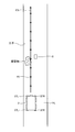
- FIG. 10 is a diagram for explaining traveling control and direction indicator control for the dump truck according to the present embodiment.
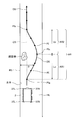
- FIG. 11 is a diagram for explaining travel control and direction indicator control for the dump truck according to the present embodiment.
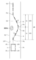
- FIG. 12 is a diagram for explaining travel control and direction indicator control for the dump truck according to the present embodiment.
- FIG. 1 is a diagram illustrating an example of a work machine management system 1 according to the present embodiment.
- the management system 1 manages the mining machine 4.
- the management of the mining machine 4 is at least one of operation management of the mining machine 4, evaluation of the productivity of the mining machine 4, evaluation of operation technology of the operator of the mining machine 4, maintenance of the mining machine 4, and abnormality diagnosis of the mining machine 4. Including one.
- Mining machine 4 is a general term for machines used for various operations in a mine.
- the mining machine 4 includes at least one of a boring machine, an excavating machine, a loading machine, a transporting machine, a crusher, and a vehicle operated by a driver.
- the excavating machine is a mining machine for excavating a mine.
- the loading machine is a mining machine for loading a load on a transporting machine.
- the loading machine includes at least one of a hydraulic excavator, an electric excavator, and a wheel loader.
- a transport machine is a mining machine for transporting a load.
- the crusher is a mining machine that crushes the soil discharged from the transporting machine.
- the mining machine 4 is movable in the mine.
- the mining machine 4 includes a dump truck 2 which is a transport machine capable of traveling in the mine, another mining machine 3 different from the dump truck 2, and a manned vehicle 8 driven by the driver.
- a dump truck 2 which is a transport machine capable of traveling in the mine
- another mining machine 3 different from the dump truck 2 and a manned vehicle 8 driven by the driver.
- the dump truck 2 is mainly managed by the management system 1.
- the dump truck 2 travels at least a part of the mine work area PA and the conveyance path HL leading to the work place PA.
- the work place PA includes at least one of a loading place LPA and a dumping place DPA.
- the conveyance path HL includes an intersection IS.
- the dump truck 2 travels according to course data indicating the target travel route set in the transport path HL and the work place PA.
- the loading site LPA is a range in which loading work for loading the dump truck 2 is performed.
- the earth removal site DPA is a range in which a discharge operation for discharging the load from the dump truck 2 is performed.
- a crusher CR is provided in at least a part of the earth removal site DPA.
- the dump truck 2 is an unmanned dump truck that autonomously travels in a mine based on a command signal from the management device 10.
- the autonomous traveling of the dump truck 2 refers to traveling based on a command signal from the management device 10 without depending on the operation of the driver.
- the management system 1 includes a management device 10 disposed in a control facility 7 installed in a mine, and a communication system 9.
- the communication system 9 includes a plurality of repeaters 6 that relay data or command signals.
- the communication system 9 wirelessly communicates data or command signals between the management device 10 and the mining machine 4.
- the communication system 9 wirelessly communicates data or command signals among the plurality of mining machines 4.
- GNSS Global Navigation Satellite System
- GPS Global Positioning System
- the GNSS has a plurality of positioning satellites 5.
- the GNSS detects a position defined by latitude, longitude, and altitude coordinate data.
- the position detected by GNSS is an absolute position defined in the global coordinate system.
- the position of the dump truck 2 and the position of the other mining machine 3 in the mine are detected by the GNSS.
- the position detected by the GNSS is appropriately referred to as a GPS position.
- the GPS position is an absolute position and includes latitude, longitude, and altitude coordinate data.
- the absolute position includes the estimated position of the dump truck 2 estimated with high accuracy.
- the management device 10 transmits data or a command signal to the mining machine 4 and receives data from the mining machine 4.
- the management device 10 includes a computer 11, a display device 16, an input device 17, and a wireless communication device 18.
- the computer 11 includes a processing device 12, a storage device 13, and an input / output unit 15.
- the display device 16, the input device 17, and the wireless communication device 18 are connected to the computer 11 via the input / output unit 15.
- the processing device 12 performs arithmetic processing for managing the mining machine 4.
- the storage device 13 is connected to the processing device 12 and stores data for managing the mining machine 4.
- the input device 17 is operated by an administrator to generate input data for managing the mining machine 4 and supply the input data to the processing device 12.
- the input device 17 includes, for example, at least one of a keyboard for a computer, a mouse, and a touch sensor provided on the display screen of the display device 16.
- the display device 16 includes a flat panel display such as a liquid crystal display.
- the processing device 12 performs arithmetic processing using data stored in the storage device 13, data input from the input device 17, and data acquired via the communication system 9.
- the display device 16 displays the arithmetic processing result of the processing device 12 and the like.
- the wireless communication device 18 has an antenna 18A and is disposed in the control facility 7.
- the wireless communication device 18 is connected to the processing device 12 via the input / output unit 15.
- the communication system 9 includes a wireless communication device 18.
- the wireless communication device 18 can receive data transmitted from the mining machine 4. Data received by the wireless communication device 18 is output to the processing device 12 and stored in the storage device 13. The wireless communication device 18 can transmit data to the mining machine 4.
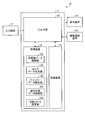
- FIG. 2 is a functional block diagram illustrating an example of the management apparatus 10 according to the present embodiment.
- the processing device 12 of the management device 10 includes an obstacle data acquisition unit 121 that acquires position data of an obstacle existing in the transport path HL or the work place PA, and a course that indicates a traveling course of the dump truck 2.
- a course data generation unit 122 that generates data, a detour course setting unit 126 that sets detour course data that is a detour course of the dump truck 2 that travels according to the course data based on the position data of the obstacle, and a dump in the detour course
- a winker data setting unit 123 that sets winker data for controlling the direction indicator 37 of the truck 2 and an absolute position data acquisition unit 124 that acquires absolute position data of the dump truck 2 are provided.
- the blinker data is output from the input / output unit 15 functioning as an output unit to the dump truck 2 that travels according to the course data via the wireless communication device 18.
- the blinker data is stored in the storage device 13.
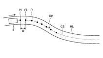
- FIG. 3 is a schematic diagram showing the dump truck 2 traveling on the conveyance path HL.
- the course data generation unit 122 of the processing device 12 generates traveling condition data including the course data of the dump truck 2 traveling in the mine.
- the traveling condition data includes an aggregate of a plurality of course points PI set at a constant interval W.
- Each of the plurality of course points PI includes the target absolute position data of the dump truck 2, the target travel speed data of the dump truck 2 at the position where the course point PI is set, and the dump truck 2 at the position where the course point PI is set.
- Target orientation data The target travel route RP is defined by course data CS that is an aggregate of a plurality of course points PI.
- a target travel route RP of the dump truck 2 is defined by a trajectory passing through a plurality of course points PI. Based on the target travel speed data, the target travel speed of the dump truck 2 at the position where the course point PI is set is defined. Based on the target bearing data, the bearing of the dump truck 2 at the position where the course point PI is set is defined.
- Each of the plurality of course points PI includes turn signal data for controlling the direction indicator 37 of the dump truck 2.
- the blinker data is data indicating the operating condition of the direction indicator 37 when the dump truck 2 passes the position of the course point PI.
- the turn signal data includes data for turning on the turn signal lamp 37R for turning right of the direction indicator 37, data for turning on the turn signal lamp 37L for turning left of the direction indicator 37, turn signal lamp 37R for turning right and turn signal lamp for turning left. This includes data for turning on the light 37L simultaneously and data for turning off the turn signal lamp 37R and the turn signal lamp 37L.
- the winker data setting unit 123 sets the winker data in the course point PI based on the detour course data set by the detour course setting unit 126 of the management device 10.
- Each of the plurality of course points PI includes target absolute position data, target travel speed data, target azimuth data, and blinker data.
- the management device 10 outputs traveling condition data including a plurality of course points PI ahead in the traveling direction to the dump truck 2 via the wireless communication device 18.
- the dump truck 2 travels in the mine according to the travel condition data transmitted from the management device 10.
- the dump truck 2 controls the direction indicator 37 according to the winker data transmitted from the management device 10.
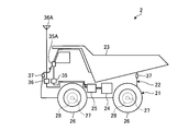
- 4 and 5 are diagrams schematically showing an example of the dump truck 2 according to the present embodiment.
- the dump truck 2 includes a traveling device 21 capable of traveling in a mine, a vehicle main body 22 supported by the traveling device 21, a vessel 23 supported by the vehicle main body 22, a drive device 24 that drives the traveling device 21, and a direction.
- An indicator 37 and a control device 25 are provided.
- the traveling device 21 includes a wheel 26, an axle 27 that rotatably supports the wheel 26, a brake device 28 that brakes the traveling device 21, and a steering device 29 that can adjust the traveling direction.
- the traveling device 21 is operated by the driving force generated by the driving device 24.
- the driving device 24 generates a driving force for accelerating the dump truck 2.
- the drive device 24 drives the traveling device 21 by an electric drive method.
- the drive device 24 includes an internal combustion engine such as a diesel engine, a generator that operates by power of the internal combustion engine, and an electric motor that operates by electric power generated by the generator.
- the driving force generated by the electric motor is transmitted to the wheels 26 of the traveling device 21. Thereby, the traveling device 21 is driven.
- the dump truck 2 is self-propelled by the driving force of the driving device 24 provided in the vehicle body 22.
- the traveling speed of the dump truck 2 is adjusted by adjusting the output of the driving device 24.
- the driving device 24 may drive the traveling device 21 by a mechanical driving method. For example, power generated in the internal combustion engine may be transmitted to the wheels 26 of the traveling device 21 via a power transmission device.
- the steering device 29 can adjust the traveling direction of the traveling device 21.
- the traveling direction of the dump truck 2 including the traveling device 21 includes the direction of the front portion of the vehicle main body 22.
- the steering device 29 adjusts the traveling direction of the dump truck 2 by changing the direction of the wheels 26.
- the brake device 28 generates a braking force for decelerating or stopping the dump truck 2.
- the control device 25 outputs an accelerator command signal for operating the drive device 24, a brake command signal for operating the brake device 28, and a steering command signal for operating the steering device 29.
- the driving device 24 generates a driving force for accelerating the dump truck 2 based on the accelerator command signal output from the control device 25.
- the brake device 28 generates a braking force for decelerating the dump truck 2 based on the brake command signal output from the control device 25.
- the steering device 29 generates a force for changing the direction of the wheels 26 in order to make the dump truck 2 go straight or turn based on the steering command signal output from the control device 25.
- the direction indicator 37 displays the traveling direction of the dump truck 2.
- the direction indicator 37 is disposed at each of the front part and the rear part of the vehicle main body 22.
- the direction indicator 37 includes a blinker lamp, and notifies the surroundings of the traveling direction of the dump truck 2 by lighting or blinking the blinker lamp.
- the direction indicator 37 includes a right turn turn signal lamp 37R that is turned on when the dump truck 2 makes a right turn, and a left turn turn signal lamp 37L that is turned on when the dump truck 2 makes a left turn.
- the right turn turn signal lamp 37R is disposed on the right side of the vehicle body 22 in the vehicle width direction of the dump truck 2
- the left turn turn signal lamp 37L is disposed on the left side of the vehicle body 22 in the vehicle width direction of the dump truck 2. .
- lighting of the blinker lamp 37R is appropriately referred to as right-turn lighting
- lighting of the blinker lamp 37L is appropriately referred to as left-turn lighting.
- the dump truck 2 includes a travel speed detector 31 that detects the travel speed of the dump truck 2, an acceleration detector 32 that detects the acceleration of the dump truck 2, and a position detector 35 that detects the position of the dump truck 2. And a wireless communication device 36.
- the traveling speed detector 31 detects the traveling speed of the dump truck 2.
- the traveling speed detector 31 includes a rotational speed sensor that detects the rotational speed of the wheel 26. Since the rotational speed of the wheel 26 and the traveling speed of the dump truck 2 are correlated, the rotational speed value detected by the rotational speed sensor is converted into the traveling speed value of the dump truck 2.
- the traveling speed detector 31 may detect the rotational speed of the wheel 26.
- the acceleration detector 32 detects the acceleration of the dump truck 2.
- the acceleration of the dump truck 2 includes a positive acceleration and a negative acceleration (deceleration).
- calculation processing is performed based on a rotation speed value that is a detection value of a rotation speed sensor that detects the rotation speed of the wheel 26, thereby converting the acceleration value of the dump truck 2.
- the traveling speed detector 31 and the acceleration detector 32 may be separate detectors.
- the position detector 35 includes a GPS receiver, and detects the GPS position (coordinates) of the dump truck 2.
- the position detector 35 has a GPS antenna 35A.
- the antenna 35 ⁇ / b> A receives radio waves from the positioning satellite 5.
- the position detector 35 converts a signal based on the radio wave from the positioning satellite 5 received by the antenna 35A into an electric signal, and calculates the position of the antenna 35A.
- the GPS position of the dump truck 2 is detected by calculating the GPS position of the antenna 35A.
- the communication system 9 includes a wireless communication device 36 provided in the dump truck 2.
- the wireless communication device 36 has an antenna 36A.
- the wireless communication device 36 can wirelessly communicate with the management device 10.
- the management device 10 transmits a command signal including travel condition data of the dump truck 2 to the control device 25 via the communication system 9. Based on the travel condition data supplied from the management device 10, the control device 25 travels the dump truck 2 according to the travel condition data (including absolute position data, target travel speed, and target azimuth angle at a plurality of course points PI). In this manner, at least one of the drive device 24, the brake device 28, and the steering device 29 of the dump truck 2 is controlled.
- the travel condition data including absolute position data, target travel speed, and target azimuth angle at a plurality of course points PI.
- the dump truck 2 transmits absolute position data indicating the absolute position of the dump truck 2 detected by the position detector 35 to the management apparatus 10 via the communication system 9.
- the absolute position data acquisition unit 124 of the management device 10 acquires absolute position data of a plurality of dump trucks 2 traveling in the mine. Further, the absolute position data acquisition unit 124 of the management device 10 acquires not only the dump truck 2 but also absolute position data of other mining machines 3 including the position detector 35.
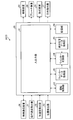
- FIG. 6 is a control block diagram of the control system 20 according to the present embodiment.
- the control system 20 is mounted on the dump truck 2.
- the control system 20 includes a wireless communication device 36, a travel speed detector 31, an acceleration detector 32, a position detector 35, a control device 25, a drive device 24, and a brake device 28. And a steering device 29 and a direction indicator 37.
- the control device 25 includes an input / output unit 41, an operation control unit 42, a winker data acquisition unit 43, a winker control unit 44, an absolute position data acquisition unit 45, and a storage unit 46.
- the input / output unit 41 includes turn signal data and travel condition data output from the management device 10, travel speed data indicating the travel speed of the dump truck 2 output from the travel speed detector 31, and dump output from the acceleration detector 32.
- the acceleration data indicating the acceleration of the track 2 and the position data indicating the position of the dump truck 2 output from the position detector 35 are acquired.
- the input / output unit 41 outputs an accelerator command signal to the drive device 24, outputs a brake command signal to the brake device 28, and outputs a steering command signal to the steering device 29.
- the operation control unit 42 outputs an operation control signal for controlling the traveling device 21 of the dump truck 2 based on the designated traveling condition data.
- the traveling device 21 includes a brake device 28 and a steering device 29.
- the driving control unit 42 outputs a driving control signal to the traveling device 21 including the driving device 24, the brake device 28, and the steering device 29.
- the driving control signal includes an accelerator signal output to the drive device 24, a brake command signal output to the brake device 28, and a steering command signal output to the steering device 29.
- the winker data acquisition unit 43 acquires the winker data output from the management device 10 in order to control the direction indicator 37 of the dump truck 2.
- the winker control unit 44 outputs a winker control signal to the direction indicator 37 provided in the dump truck 2 based on the winker data acquired by the winker data acquisition unit 43.
- the blinker control signal includes a lighting signal for turning on the direction indicator 37 and a turn-off signal for turning off the direction indicator 37.
- the lighting signal includes a right turn lighting signal, a left turn lighting signal, and a hazard lighting signal that simultaneously performs right turn lighting and left turn lighting.
- the absolute position data acquisition unit 45 acquires the absolute position data of the dump truck 2 from the detection data of the position detector 35.
- the storage unit 46 stores the traveling condition data of the dump truck 2 acquired by the wireless communication device 36.
- the traveling condition data includes turn signal data for controlling the direction indicator 37.
- FIG. 7 is a diagram schematically illustrating an example of the manned vehicle 8 according to the present embodiment.
- FIG. 8 is a control block diagram of the control system for the manned vehicle 8 according to the present embodiment.
- the control system for the manned vehicle 8 is mounted on the manned vehicle 8.
- the manned vehicle 8 has a driver's cab in which the driver WM is boarded.
- the manned vehicle 8 is operated by a driver WM boarding the driver's cab.
- the manned vehicle 8 is, for example, a passenger vehicle type vehicle and is smaller than the dump truck 2.
- the manned vehicle 8 has a position detector 85 that acquires position data of the manned vehicle 8.
- the position detector 85 includes a GPS receiver and detects the GPS position (coordinates) of the manned vehicle 8.
- the control system for the manned vehicle 8 includes a computer 80, a wireless communication device 84, a position detector 85, an input device 88, and a display device 89.
- the wireless communication device 84 performs wireless communication via the antenna 84A.
- the input device 88 and the display device 89 are provided in the cab of the manned vehicle 8.
- the computer 80 includes an input / output unit 81, an arithmetic processing unit 82, and a storage unit 83.
- the arithmetic processing unit 82 acquires the position data of the manned vehicle 8 detected by the position detector 85. In addition, the arithmetic processing unit 82 acquires input data generated by operating the input device 88.
- the storage unit 83 stores input data from the input device 88.
- the input / output unit 81 outputs the position data of the manned vehicle 8 and the input data generated by operating the input device 88 to the management device 10 via the wireless communication device 84.
- the input / output unit 81 may output the position data and the input data to the dump truck 2 via the wireless communication device 84.
- the wireless communication device 84 can perform data communication with the management device 10 and the dump truck 2.
- the communication system 9 includes a wireless communication device 84.
- the input device 88 and the display device 89 are disposed in the cab of the manned vehicle 8.
- the input device 88 generates input data for managing the mining machine 4 and supplies it to the computer 80 by being operated by the driver WM.
- the input device 88 includes, for example, at least one of a keyboard for a computer, a mouse, and a touch sensor provided on the display screen of the display device 89.
- the display device 89 includes a flat panel display such as a liquid crystal display.
- FIG. 9 is a flowchart illustrating an example of the operation of the management system 1 according to the present embodiment.
- traveling condition data including the course data CS of the dump truck 2 is generated (step SP1).
- the generated traveling condition data is transmitted from the management device 10 to the dump truck 2.
- the dump truck 2 travels on the transport path HL or the work place PA according to the travel conditions including the course data CS.
- an obstacle exists in the transport path HL.
- the obstacle include a stone that has fallen on the conveyance path HL, a depressed portion of the conveyance path HL, and a vehicle that is stopped due to a failure or the like.
- FIG. 10 is an example schematically showing an example in which an obstacle exists in the transport path HL. As illustrated in FIG. 10, for example, if an obstacle is left on the course indicated by the course data CS, the dump truck 2 traveling according to the course data CS is prevented from traveling. As a result, mine productivity is reduced.
- the manned vehicle 8 When the dump truck 2 is in operation, the manned vehicle 8 is traveling around the mine for early detection of obstacles or early detection of accidents. In the present embodiment, the manned vehicle 8 traveling around the mine transmits the position data of the obstacle to the management device 10.
- the driver WM of the manned vehicle 8 finds an obstacle on the transport path HL
- the manned vehicle 8 moves to the vicinity of the obstacle.
- the driver WM operates the input device 88 in a state where the manned vehicle 8 is disposed near the obstacle, and generates input data indicating that the obstacle exists on the transport path HL.
- the arithmetic processing unit 82 acquires input data from the input device 88 and position data from the position detector 85.
- the manned vehicle 8 and the obstacle are close to each other, and the GPS position of the manned vehicle 8 is substantially equal to the GPS position of the obstacle. Therefore, the position data of the manned vehicle 8 arranged near the obstacle can be regarded as the position data of the obstacle.
- the arithmetic processing unit 82 generates position data indicating the position of the obstacle based on the position data of the manned vehicle 8 when the input data is input.
- the input device 88 and the display device 89 are integrated, and the driver WM inputs obstacle position data discovered while referring to the mine map displayed on the display device 89 by the input device 88.
- the position data may be transmitted to the management apparatus 10.
- the arithmetic processing unit 82 transmits the position data of the obstacle to the management device 10 via the input / output unit 81 and the wireless communication device 84.
- the obstacle data acquisition unit 121 of the management apparatus 10 acquires obstacle position data (step SP2).
- the detour course setting unit 126 of the management apparatus 10 sets detour course data indicating the detour course of the dump truck 2 traveling according to the course data CS based on the obstacle position data acquired by the obstacle data acquisition unit 121. (Step SP3).
- FIG. 11 is a schematic diagram for explaining detour course data DS according to the present embodiment.
- detour course data DS there is an object beside the traveling course indicated by the course data CS.
- a bank or an artificial structure is exemplified as an object that exists beside the traveling course.
- a reflective member or a guardrail is illustrated, for example.
- the bank position data is known data and is stored in the storage device 13.
- the bank position data is acquired, for example, by a position investigation operation of the conveyance path HL performed in advance by the manned vehicle 8.
- the course data setting unit 122 sets the course data CS based on the bank position data stored in the storage device 13. That is, the course data setting unit 122 sets the course data CS so that the dump truck 2 does not hit the bank with reference to the position data of the bank.
- the course data CS is set so as to be substantially parallel to the bank.
- a course defined by the bank and parallel to the course data CS is appropriately referred to as a reference course.
- the reference course data RS indicating the reference course includes bank position data.
- the reference course data RS is set beside the course data CS.
- the reference course data RS may be set along the bank edge.
- the detour course data DS is set so as to avoid obstacles. Since there is an obstacle on the traveling course indicated by the course data CS, the detour course setting unit 126 sets the detour course so as to avoid the obstacle based on the position data of the obstacle.
- the course data CS is set so that the dump truck 2 travels in the left lane of the conveyance path HL. That is, the course data CS is set so that the dump truck 2 travels near the left bank with respect to the traveling direction. Therefore, the detour course setting unit 126 sets the detour course data DS on the right side of the course data CS. Thereby, the dump truck 2 can travel on the conveyance path HL without hitting the left bank.
- the bypass course setting unit 126 sets a bypass course with reference to the reference course. As shown in FIG. 11, the detour course approaches the reference course after the dump truck 2 passes an obstacle, and the first range AR1 in which the dump truck 2 travels to the right from the reference course defined by the bank. And a second range AR2 in which the dump truck 2 travels.
- the detour course data DS is set to branch to the right from the course point PIa of the course data CS, and then set to merge with the course data CS at the course point PIb of the course data CS.
- the course point PIa is set backward (a front side in the traveling direction) by the first distance La from the position of the obstacle in the traveling direction of the dump truck 2.
- the course point PIb is set in front of the obstacle in the traveling direction of the dump truck 2 by the second distance Lb (back side in the traveling direction).
- the course point PIa is a branch point between the course data CS and the detour course data DS.
- the course point PIb is a junction between the course data CS and the detour course data DS.
- the detour course data DS includes a course point PIc that is closest to the position data of the obstacle and is a point where the dump truck 2 faces the same direction as the traveling direction of the transport path HL when traveling.
- the first range AR1 is a range between the course point PIa and the course point PIc in the traveling direction of the dump truck 2.
- the second range AR2 is a range between the course point PIc and the course point PIb in the traveling direction of the dump truck 2.
- the turn signal data setting unit 123 sets turn signal data for controlling the direction indicator 37 of the dump truck 2 (step SP4).
- the turn signal data setting unit 123 sets turn signal data based on the deviation amount D between the reference course and the detour course.
- the turn signal data setting unit 123 includes a course point PIa defined at a position behind the course point PIc indicating the position of the obstacle in the traveling direction of the dump truck 2 by the first distance La, and a course point indicating the position of the obstacle.
- the blinker data is set so that the direction indicator 37 operates in the range AR between the course point PIb defined at a position ahead of the PIc by the second distance Lb.
- the winker data setting unit 123 includes a course point PIa indicating the position of the branch point between the course data CS and the detour course data DS, and a course point PIb indicating the position of the junction between the course data CS and the detour course data DS.
- turn signal data is set.
- the operation of the direction indicator 37 is started at the course point PIa which is the position of the branch point between the course data CS and the detour course data DS, and the course point PIb which is the position of the confluence of the course data CS and the detour course data DS.
- the blinker data may be set so that the direction indicator 37 operates from the front of the course point PIa, or the blinker data may be set so that the direction indicator 37 turns off behind the course point PIb. .
- the winker data setting unit 123 controls the direction indicator 37 of the dump truck 2 based on the deviation amount D between the reference course data RS indicating the reference course and the bypass course data DS indicating the bypass course. Set the blinker data for.
- the dump truck 2 travels in the traveling direction while moving to the right so as to be away from the reference course data RS according to the detour course data DS.
- the deviation amount D between the reference course data RS and the detour course data DS gradually increases in the traveling direction of the dump truck 2.
- the dump truck 2 travels in the traveling direction while moving to the left side so as to approach the reference course data RS according to the detour course data DS.
- the deviation amount D between the reference course data RS and the detour course data DS gradually decreases in the traveling direction of the dump truck 2.
- the turn signal data setting unit 123 sets the turn signal data so that the turn signal lamp 37R operates in the first range AR1, and the turn signal lamp 37L operates in the second range AR2.
- the winker data setting unit 123 sets the winker data in the detour course data DS generated by the detour course generation unit 122.
- the turn signal data setting unit 123 operates the turn signal lamp 37R to each of the course point PIa and the plurality of course points PI between the course point PIa and the course point PIc among the plurality of course points PI of the detour course data DS.
- the turn signal data setting unit 123 sets a turn signal lamp 37L to each of the course point PIb and the plurality of course points PI between the course point PIb and the course point PIc among the plurality of course points PI of the detour course data DS.
- turn signal data may be added to the course point PI behind (front side) the course point PIa and the course point PI ahead (back side) from the course point PIb. .
- the input / output unit 15 of the management device 10 outputs traveling condition data including turn signal data and course data CS to the dump truck 2 via the wireless communication device 18 (step SP5).
- the dump truck 2 controls the direction indicator 37 according to the winker data supplied from the management device 10.
- the blinker lamp 37R is lit or blinks.
- the blinker lamp 37L is lit or blinks.
- the detour course data DS that is set when the course data CS is set near the left bank and the dump truck 2 travels in the left lane of the conveyance path HL has been described.
- the dump truck 2 moves while moving to the left side.
- the detour course data DS is set so as to travel in the direction away from the reference course data RS (right bank).
- the detour course data DS is set so that the dump truck 2 travels in the traveling direction while moving to the right and approaches the reference course data RS (right bank).
- the blinker data is set so that the blinker lamp 37L operates in the first range AR1, and the blinker lamp 37R operates in the second range AR2.
- the detour course setting unit 126 moves the dump truck 2 to the other side in the vehicle width direction in the first range AR1.
- the bypass course data DS is set so as to travel in the traveling direction, and the bypass course data DS is set so that the dump truck 2 travels in the traveling direction while moving to one side in the vehicle width direction in the second range AR2.
- the winker data setting unit 123 the winker lamp provided on the other side in the vehicle width direction operates in the first range AR1, and the winker lamp provided on one side in the vehicle width direction operates in the second range AR2.
- the blinker data is set.
- turn signal data for controlling the direction indicator 37 of the dump truck 2 is set in the set detour course data DS. Since the direction indicator 37 is controlled based on the set turn signal data, the driver of the manned vehicle 8 around the dump truck 2 or the worker working in the mine determines the traveling direction of the dump truck 2. I can grasp it. Therefore, the safety of the mine is improved.
- the blinker data is set based on the deviation amount D between the reference course and the detour course. In the present embodiment, the blinker data is set based on at least one of the position of the branch point between the course data CS and the detour course data DS and the position of the junction point between the course data CS and the detour course data DS.
- the winker data setting unit 123 is behind the first distance La in the traveling direction of the dump truck 2 with respect to the obstacle position data acquired by the manned vehicle 8 as a reference.
- the blinker data is set so that the direction indicator 37 operates between the position and the position ahead of the obstacle by the second distance Lb.
- the detour course includes the first range AR1 in which the dump truck 2 travels away from the reference course in the traveling direction of the dump truck 2, and the reference course after the dump truck 2 passes an obstacle. And a second range AR2 in which the dump truck 2 travels so as to approach the vehicle.
- the winker data setting unit 123 the winker lamp farther from the reference course among the winker lamp 37R and the winker lamp 37L operates in the first range AR1, and the winker lamp closer to the reference course operates in the second range AR2.
- the blinker data is set.
- the turn signal lamp of an appropriate one of the turn signal lamp 37R and the turn signal lamp 37L can be operated on the basis of the reference course. Further, the dump truck 2 can bypass an obstacle without hitting the bank.
- the deviation amount D between the reference course and the detour course is a deviation amount of the distance between the reference course and the detour course in a direction (lateral direction) orthogonal to the traveling direction of the dump truck 2. It was.
- the deviation amount D may be a deviation amount between the target direction of the dump truck 2 in the reference course at the same position in the traveling direction of the dump truck 2 and the target direction of the dump truck 2 in the detour course.
- FIG. 12 is a schematic diagram for explaining detour course data DS according to the present embodiment. Similar to the above-described embodiment, the detour course data DS includes a plurality of course points PI.
- each of the plurality of course points PI is set with not only the target absolute position data of the dump truck 2 and the target traveling speed data of the dump truck 2 at the position where the course point PI is set, but also the course point PI.
- the target azimuth data of the dump truck 2 at the selected position is included.
- the turn signal data setting unit 123 sets the target azimuth in the reference course and the target azimuth in the detour course. Based on the deviation amount ⁇ , the blinker lamp 37R is turned on or blinked.
- the blinker data setting unit 123 determines the deviation amount between the target azimuth in the reference course and the target azimuth in the detour course. Based on ⁇ , the blinker lamp 37L is turned on or blinked.
- the reference course data RS is set based on the bank beside the course data CS.
- the reference course data RS may not be set based on the bank.
- the reference course data RS may be the course data CS before the detour course data DS is generated.
- the turn signal data set by the turn signal data setting unit 123 is added to the drive condition data generated by the course data generation unit 122, and the drive condition data including the turn signal data is stored in the management device. 10 to be sent to the dump truck 2.
- the traveling condition data may be transmitted from the management device 10 to the dump truck 2
- the blinker data may be transmitted from the management device 10 to the dump truck 2 traveling according to the traveling condition data at predetermined time intervals.
- the position data of the obstacle is output from the manned vehicle 8 to the management device 10.
- Obstacle position data may be output from the manned vehicle 8 to the dump truck 2.
- the control system 20 of the dump truck 2 may set the blinker data based on the traveling condition data supplied from the management device 10 and the obstacle position data supplied from the manned vehicle 8.
- an obstacle detection sensor is provided in front of the dump truck 2, and when the obstacle in front of the dump truck 2 is detected while traveling, the position data of the obstacle is transmitted to the management device 10. May be.
- the dump truck 2 is an unmanned dump truck.
- the dump truck 2 may be a manned dump truck that travels according to a driver's operation.
- an operating device such as a winker lever for operating the direction indicator 37 is provided, and the operating device is operated by the driver.
- the control system 20 intervenes in the operation of the operating device even if the driver neglects to operate the operating device, and turns on or blinks the direction indicator 37. That is, the control system 20 performs so-called assist control that assists the operation of the driver. This ensures the safety of the mine.
- the work machine is a dump truck that operates in a mine on the ground.
- the work machine may be a mining machine such as a wheel loader operating in a mine on the ground.
- the working machine is described as an example of a mining machine operating in a mine, but is not limited to a mining machine.
- the components described in the above-described embodiments can be applied to any work machine used at a work site.
- SYMBOLS 1 Management system, 2 ... Dump truck (mining machine), 3 ... Other mining machine, 4 ... Mining machine, 5 ... Positioning satellite, 6 ... Repeater, 7 ... Control facility, 8 ... Manned vehicle, 9 ... Communication system DESCRIPTION OF SYMBOLS 10 ... Management apparatus, 11 ... Computer, 12 ... Processing apparatus, 13 ... Memory
Landscapes
- Engineering & Computer Science (AREA)
- Physics & Mathematics (AREA)
- General Physics & Mathematics (AREA)
- Mechanical Engineering (AREA)
- Remote Sensing (AREA)
- Aviation & Aerospace Engineering (AREA)
- Automation & Control Theory (AREA)
- Radar, Positioning & Navigation (AREA)
- General Engineering & Computer Science (AREA)
- Structural Engineering (AREA)
- Civil Engineering (AREA)
- Mining & Mineral Resources (AREA)
- Electromagnetism (AREA)
- Theoretical Computer Science (AREA)
- Transportation (AREA)
- Health & Medical Sciences (AREA)
- Public Health (AREA)
- Multimedia (AREA)
- Control Of Position, Course, Altitude, Or Attitude Of Moving Bodies (AREA)
- Operation Control Of Excavators (AREA)
- Component Parts Of Construction Machinery (AREA)
- Lighting Device Outwards From Vehicle And Optical Signal (AREA)
- Traffic Control Systems (AREA)
Abstract
Description
Claims (7)
- 障害物の位置データを取得する障害物データ取得部と、
前記障害物の位置データに基づいて、作業機械が走行するコースデータの迂回コースである迂回コースデータを設定する迂回コース設定部と、
前記迂回コースにおいて前記作業機械の方向指示器を制御するためのウインカーデータを設定するウインカーデータ設定部と、
前記作業機械に前記ウインカーデータを出力する出力部と、
を備える作業機械の管理システム。 - 前記ウインカーデータ設定部は、基準コースと前記迂回コースとの偏差量に基づいて前記ウインカーデータを設定する、
請求項1に記載の作業機械の管理システム。 - 前記ウインカーデータ設定部は、前記コースデータと前記迂回コースデータとの分岐点の位置に基づいて前記ウインカーデータを設定する、
請求項1に記載の作業機械の管理システム。 - 前記ウインカーデータ設定部は、前記作業機械の進行方向において前記障害物の位置よりも第1距離後方の位置と、前記障害物の位置よりも第2距離前方の位置との間において前記方向指示器が作動するように前記ウインカーデータを設定する、
請求項1から請求項3のいずれか一項に記載の作業機械の管理システム。 - 前記迂回コースは、前記基準コースから離れるように前記作業機械を走行させる第1範囲と、前記作業機械が前記障害物を通過した後前記基準コースに近付くように前記作業機械を走行させる第2範囲とを含み、
前記方向指示器は、前記作業機械の車幅方向において右側に配置された第1ウインカーランプと、左側に配置された第2ウインカーランプとを含み、
前記ウインカーデータ設定部は、前記第1範囲において前記第1ウインカーランプ及び前記第2ウインカーランプの一方が作動し、前記第2範囲において前記第1ウインカーランプ及び前記第2ウインカーランプの他方が作動するように、前記ウインカーデータを設定する、
請求項1から請求項4のいずれか一項に記載の作業機械の管理システム。 - 前記基準コースを示す基準コースデータは、前記コースデータが示す走行コースの傍らに存在する物体の位置データを含む、
請求項5に記載の作業機械の管理システム。 - 障害物の位置データを取得することと、
前記障害物の位置データに基づいて、コースデータに従って走行する作業機械の迂回コースを設定することと、
前記迂回コースにおいて前記作業機械の方向指示器を制御するためのウインカーデータを設定することと、
前記作業機械に前記ウインカーデータを出力することと、
を含む作業機械の管理方法。
Priority Applications (3)
| Application Number | Priority Date | Filing Date | Title |
|---|---|---|---|
| US16/083,536 US10549681B2 (en) | 2016-03-31 | 2016-12-26 | Work machine management system and work machine management method |
| AU2016400807A AU2016400807B2 (en) | 2016-03-31 | 2016-12-26 | Work machine management system and work machine management method |
| CA3017291A CA3017291C (en) | 2016-03-31 | 2016-12-26 | Work machine management system and work machine management method |
Applications Claiming Priority (2)
| Application Number | Priority Date | Filing Date | Title |
|---|---|---|---|
| JP2016073239A JP6783064B2 (ja) | 2016-03-31 | 2016-03-31 | 作業機械の管理システム及び作業機械の管理方法 |
| JP2016-073239 | 2016-03-31 |
Publications (1)
| Publication Number | Publication Date |
|---|---|
| WO2017168895A1 true WO2017168895A1 (ja) | 2017-10-05 |
Family
ID=59963935
Family Applications (1)
| Application Number | Title | Priority Date | Filing Date |
|---|---|---|---|
| PCT/JP2016/088781 Ceased WO2017168895A1 (ja) | 2016-03-31 | 2016-12-26 | 作業機械の管理システム及び作業機械の管理方法 |
Country Status (5)
| Country | Link |
|---|---|
| US (1) | US10549681B2 (ja) |
| JP (1) | JP6783064B2 (ja) |
| AU (1) | AU2016400807B2 (ja) |
| CA (1) | CA3017291C (ja) |
| WO (1) | WO2017168895A1 (ja) |
Cited By (1)
| Publication number | Priority date | Publication date | Assignee | Title |
|---|---|---|---|---|
| CN110234063A (zh) * | 2018-12-21 | 2019-09-13 | 南京工程学院 | 基于uwb的室内定位方法 |
Families Citing this family (9)
| Publication number | Priority date | Publication date | Assignee | Title |
|---|---|---|---|---|
| JP2017109705A (ja) * | 2015-12-18 | 2017-06-22 | 株式会社小松製作所 | 作業機械の管理システム、作業機械の制御システム、及び作業機械 |
| JP6712906B2 (ja) * | 2016-05-31 | 2020-06-24 | 株式会社小松製作所 | 作業機械の管理装置、作業機械、及び作業機械の管理システム |
| JPWO2020101007A1 (ja) * | 2018-11-14 | 2021-09-30 | 住友建機株式会社 | ショベル、ショベルの制御装置、ショベルの支援装置 |
| JP7267438B2 (ja) * | 2019-03-08 | 2023-05-01 | ウェイモ エルエルシー | 自律車両のターンのシグナリング |
| CN113561171B (zh) * | 2020-01-05 | 2023-03-24 | 牧今科技 | 具有动态运动调整机制的机器人系统及其操作方法 |
| JP7100413B1 (ja) * | 2021-09-15 | 2022-07-13 | 日立建機株式会社 | 自律走行鉱山車両 |
| JP2024005692A (ja) * | 2022-06-30 | 2024-01-17 | 住友重機械工業株式会社 | ショベル、及び、ショベルの制御システム |
| US12377776B2 (en) * | 2022-10-20 | 2025-08-05 | Motional Ad Llc | Turn signal assignment for complex maneuvers |
| JP2025153388A (ja) * | 2024-03-29 | 2025-10-10 | コベルコ建機株式会社 | 走行計画設定システム |
Citations (5)
| Publication number | Priority date | Publication date | Assignee | Title |
|---|---|---|---|---|
| JPS63307506A (ja) * | 1987-06-09 | 1988-12-15 | Toyota Autom Loom Works Ltd | ウインカを備えた無人走行車 |
| JPH05324058A (ja) * | 1992-05-22 | 1993-12-07 | Meidensha Corp | 自律走行方式の無人搬送車における方向指示方式 |
| JPH11296229A (ja) * | 1998-02-13 | 1999-10-29 | Komatsu Ltd | 車両の誘導装置 |
| JP2010202021A (ja) * | 2009-03-03 | 2010-09-16 | Murata Machinery Ltd | 走行車システム |
| WO2015033708A1 (ja) * | 2014-07-30 | 2015-03-12 | 株式会社小松製作所 | 作業車両及び作業車両の制御方法 |
Family Cites Families (4)
| Publication number | Priority date | Publication date | Assignee | Title |
|---|---|---|---|---|
| JPH08263138A (ja) * | 1995-03-24 | 1996-10-11 | Komatsu Ltd | 無人ダンプ走行コースデータ作成方法及び作成装置 |
| US6876300B2 (en) * | 2002-11-25 | 2005-04-05 | Richard L. Ponziani | Electronic intelligent turn signal control system |
| US20110106376A1 (en) * | 2009-10-30 | 2011-05-05 | Louis Tijerina | System and method for automatically controlling vehicle turn signal switches |
| JP6068865B2 (ja) * | 2012-08-07 | 2017-01-25 | 矢崎総業株式会社 | 方向指示装置 |
-
2016
- 2016-03-31 JP JP2016073239A patent/JP6783064B2/ja active Active
- 2016-12-26 CA CA3017291A patent/CA3017291C/en active Active
- 2016-12-26 WO PCT/JP2016/088781 patent/WO2017168895A1/ja not_active Ceased
- 2016-12-26 AU AU2016400807A patent/AU2016400807B2/en active Active
- 2016-12-26 US US16/083,536 patent/US10549681B2/en active Active
Patent Citations (5)
| Publication number | Priority date | Publication date | Assignee | Title |
|---|---|---|---|---|
| JPS63307506A (ja) * | 1987-06-09 | 1988-12-15 | Toyota Autom Loom Works Ltd | ウインカを備えた無人走行車 |
| JPH05324058A (ja) * | 1992-05-22 | 1993-12-07 | Meidensha Corp | 自律走行方式の無人搬送車における方向指示方式 |
| JPH11296229A (ja) * | 1998-02-13 | 1999-10-29 | Komatsu Ltd | 車両の誘導装置 |
| JP2010202021A (ja) * | 2009-03-03 | 2010-09-16 | Murata Machinery Ltd | 走行車システム |
| WO2015033708A1 (ja) * | 2014-07-30 | 2015-03-12 | 株式会社小松製作所 | 作業車両及び作業車両の制御方法 |
Cited By (1)
| Publication number | Priority date | Publication date | Assignee | Title |
|---|---|---|---|---|
| CN110234063A (zh) * | 2018-12-21 | 2019-09-13 | 南京工程学院 | 基于uwb的室内定位方法 |
Also Published As
| Publication number | Publication date |
|---|---|
| CA3017291A1 (en) | 2017-10-05 |
| AU2016400807A1 (en) | 2018-12-13 |
| JP6783064B2 (ja) | 2020-11-11 |
| US20190084474A1 (en) | 2019-03-21 |
| JP2017182723A (ja) | 2017-10-05 |
| AU2016400807B2 (en) | 2020-03-12 |
| CA3017291C (en) | 2020-12-15 |
| US10549681B2 (en) | 2020-02-04 |
Similar Documents
| Publication | Publication Date | Title |
|---|---|---|
| AU2016400807B2 (en) | Work machine management system and work machine management method | |
| CN105939893B (zh) | 作业机械的控制系统、作业机械、作业机械的管理系统及作业机械的管理方法 | |
| AU2019275632B2 (en) | Work machine management system, work machine control system, and work machine | |
| JP6712906B2 (ja) | 作業機械の管理装置、作業機械、及び作業機械の管理システム | |
| CA3074570C (en) | Safe driving assistance device | |
| AU2016400806B2 (en) | Work machine management system | |
| US20230229169A1 (en) | Unmanned vehicle control system, unmanned vehicle, and unmanned vehicle control method | |
| US12017579B2 (en) | Work site management system and work site management method | |
| US20220212597A1 (en) | System of controlling unmanned vehicle and method of controlling unmanned vehicle |
Legal Events
| Date | Code | Title | Description |
|---|---|---|---|
| ENP | Entry into the national phase |
Ref document number: 3017291 Country of ref document: CA |
|
| NENP | Non-entry into the national phase |
Ref country code: DE |
|
| 121 | Ep: the epo has been informed by wipo that ep was designated in this application |
Ref document number: 16897110 Country of ref document: EP Kind code of ref document: A1 |
|
| ENP | Entry into the national phase |
Ref document number: 2016400807 Country of ref document: AU Date of ref document: 20161226 Kind code of ref document: A |
|
| 122 | Ep: pct application non-entry in european phase |
Ref document number: 16897110 Country of ref document: EP Kind code of ref document: A1 |