WO2017168772A1 - Solid fuel combustion device, solid fuel combustion method, gas heating device, liquid heating device, power generation system, and cooling system - Google Patents
Solid fuel combustion device, solid fuel combustion method, gas heating device, liquid heating device, power generation system, and cooling system Download PDFInfo
- Publication number
- WO2017168772A1 WO2017168772A1 PCT/JP2016/070196 JP2016070196W WO2017168772A1 WO 2017168772 A1 WO2017168772 A1 WO 2017168772A1 JP 2016070196 W JP2016070196 W JP 2016070196W WO 2017168772 A1 WO2017168772 A1 WO 2017168772A1
- Authority
- WO
- WIPO (PCT)
- Prior art keywords
- combustion
- gas
- furnace
- solid fuel
- combustion furnace
- Prior art date
Links
Images


Classifications
-
- F—MECHANICAL ENGINEERING; LIGHTING; HEATING; WEAPONS; BLASTING
- F23—COMBUSTION APPARATUS; COMBUSTION PROCESSES
- F23B—METHODS OR APPARATUS FOR COMBUSTION USING ONLY SOLID FUEL
- F23B60/00—Combustion apparatus in which the fuel burns essentially without moving
-
- F—MECHANICAL ENGINEERING; LIGHTING; HEATING; WEAPONS; BLASTING
- F23—COMBUSTION APPARATUS; COMBUSTION PROCESSES
- F23B—METHODS OR APPARATUS FOR COMBUSTION USING ONLY SOLID FUEL
- F23B10/00—Combustion apparatus characterised by the combination of two or more combustion chambers
- F23B10/02—Combustion apparatus characterised by the combination of two or more combustion chambers including separate secondary combustion chambers
-
- F—MECHANICAL ENGINEERING; LIGHTING; HEATING; WEAPONS; BLASTING
- F23—COMBUSTION APPARATUS; COMBUSTION PROCESSES
- F23J—REMOVAL OR TREATMENT OF COMBUSTION PRODUCTS OR COMBUSTION RESIDUES; FLUES
- F23J15/00—Arrangements of devices for treating smoke or fumes
- F23J15/06—Arrangements of devices for treating smoke or fumes of coolers
-
- F—MECHANICAL ENGINEERING; LIGHTING; HEATING; WEAPONS; BLASTING
- F23—COMBUSTION APPARATUS; COMBUSTION PROCESSES
- F23M—CASINGS, LININGS, WALLS OR DOORS SPECIALLY ADAPTED FOR COMBUSTION CHAMBERS, e.g. FIREBRIDGES; DEVICES FOR DEFLECTING AIR, FLAMES OR COMBUSTION PRODUCTS IN COMBUSTION CHAMBERS; SAFETY ARRANGEMENTS SPECIALLY ADAPTED FOR COMBUSTION APPARATUS; DETAILS OF COMBUSTION CHAMBERS, NOT OTHERWISE PROVIDED FOR
- F23M7/00—Doors
- F23M7/02—Frames therefor
-
- F—MECHANICAL ENGINEERING; LIGHTING; HEATING; WEAPONS; BLASTING
- F23—COMBUSTION APPARATUS; COMBUSTION PROCESSES
- F23N—REGULATING OR CONTROLLING COMBUSTION
- F23N3/00—Regulating air supply or draught
- F23N3/08—Regulating air supply or draught by power-assisted systems
- F23N3/082—Regulating air supply or draught by power-assisted systems using electronic means
-
- F—MECHANICAL ENGINEERING; LIGHTING; HEATING; WEAPONS; BLASTING
- F23—COMBUSTION APPARATUS; COMBUSTION PROCESSES
- F23N—REGULATING OR CONTROLLING COMBUSTION
- F23N5/00—Systems for controlling combustion
- F23N5/02—Systems for controlling combustion using devices responsive to thermal changes or to thermal expansion of a medium
- F23N5/022—Systems for controlling combustion using devices responsive to thermal changes or to thermal expansion of a medium using electronic means
-
- F—MECHANICAL ENGINEERING; LIGHTING; HEATING; WEAPONS; BLASTING
- F24—HEATING; RANGES; VENTILATING
- F24B—DOMESTIC STOVES OR RANGES FOR SOLID FUELS; IMPLEMENTS FOR USE IN CONNECTION WITH STOVES OR RANGES
- F24B1/00—Stoves or ranges
- F24B1/18—Stoves with open fires, e.g. fireplaces
- F24B1/185—Stoves with open fires, e.g. fireplaces with air-handling means, heat exchange means, or additional provisions for convection heating ; Controlling combustion
- F24B1/187—Condition responsive controls for regulating combustion
-
- F—MECHANICAL ENGINEERING; LIGHTING; HEATING; WEAPONS; BLASTING
- F24—HEATING; RANGES; VENTILATING
- F24B—DOMESTIC STOVES OR RANGES FOR SOLID FUELS; IMPLEMENTS FOR USE IN CONNECTION WITH STOVES OR RANGES
- F24B1/00—Stoves or ranges
- F24B1/18—Stoves with open fires, e.g. fireplaces
- F24B1/185—Stoves with open fires, e.g. fireplaces with air-handling means, heat exchange means, or additional provisions for convection heating ; Controlling combustion
- F24B1/189—Stoves with open fires, e.g. fireplaces with air-handling means, heat exchange means, or additional provisions for convection heating ; Controlling combustion characterised by air-handling means, i.e. of combustion-air, heated-air, or flue-gases, e.g. draught control dampers
- F24B1/19—Supplying combustion-air
-
- F—MECHANICAL ENGINEERING; LIGHTING; HEATING; WEAPONS; BLASTING
- F22—STEAM GENERATION
- F22B—METHODS OF STEAM GENERATION; STEAM BOILERS
- F22B9/00—Steam boilers of fire-tube type, i.e. the flue gas from a combustion chamber outside the boiler body flowing through tubes built-in in the boiler body
- F22B9/02—Steam boilers of fire-tube type, i.e. the flue gas from a combustion chamber outside the boiler body flowing through tubes built-in in the boiler body the boiler body being disposed upright, e.g. above the combustion chamber
- F22B9/08—Steam boilers of fire-tube type, i.e. the flue gas from a combustion chamber outside the boiler body flowing through tubes built-in in the boiler body the boiler body being disposed upright, e.g. above the combustion chamber the fire tubes being in horizontal arrangement
-
- F—MECHANICAL ENGINEERING; LIGHTING; HEATING; WEAPONS; BLASTING
- F23—COMBUSTION APPARATUS; COMBUSTION PROCESSES
- F23L—SUPPLYING AIR OR NON-COMBUSTIBLE LIQUIDS OR GASES TO COMBUSTION APPARATUS IN GENERAL ; VALVES OR DAMPERS SPECIALLY ADAPTED FOR CONTROLLING AIR SUPPLY OR DRAUGHT IN COMBUSTION APPARATUS; INDUCING DRAUGHT IN COMBUSTION APPARATUS; TOPS FOR CHIMNEYS OR VENTILATING SHAFTS; TERMINALS FOR FLUES
- F23L2900/00—Special arrangements for supplying or treating air or oxidant for combustion; Injecting inert gas, water or steam into the combustion chamber
- F23L2900/15043—Preheating combustion air by heat recovery means located in the chimney, e.g. for home heating devices
-
- F—MECHANICAL ENGINEERING; LIGHTING; HEATING; WEAPONS; BLASTING
- F23—COMBUSTION APPARATUS; COMBUSTION PROCESSES
- F23N—REGULATING OR CONTROLLING COMBUSTION
- F23N2221/00—Pretreatment or prehandling
- F23N2221/08—Preheating the air
-
- F—MECHANICAL ENGINEERING; LIGHTING; HEATING; WEAPONS; BLASTING
- F23—COMBUSTION APPARATUS; COMBUSTION PROCESSES
- F23N—REGULATING OR CONTROLLING COMBUSTION
- F23N2225/00—Measuring
- F23N2225/04—Measuring pressure
-
- F—MECHANICAL ENGINEERING; LIGHTING; HEATING; WEAPONS; BLASTING
- F23—COMBUSTION APPARATUS; COMBUSTION PROCESSES
- F23N—REGULATING OR CONTROLLING COMBUSTION
- F23N2233/00—Ventilators
- F23N2233/02—Ventilators in stacks
- F23N2233/04—Ventilators in stacks with variable speed
-
- F—MECHANICAL ENGINEERING; LIGHTING; HEATING; WEAPONS; BLASTING
- F23—COMBUSTION APPARATUS; COMBUSTION PROCESSES
- F23N—REGULATING OR CONTROLLING COMBUSTION
- F23N2233/00—Ventilators
- F23N2233/06—Ventilators at the air intake
- F23N2233/08—Ventilators at the air intake with variable speed
-
- F—MECHANICAL ENGINEERING; LIGHTING; HEATING; WEAPONS; BLASTING
- F23—COMBUSTION APPARATUS; COMBUSTION PROCESSES
- F23N—REGULATING OR CONTROLLING COMBUSTION
- F23N2241/00—Applications
- F23N2241/02—Space-heating
-
- F—MECHANICAL ENGINEERING; LIGHTING; HEATING; WEAPONS; BLASTING
- F24—HEATING; RANGES; VENTILATING
- F24B—DOMESTIC STOVES OR RANGES FOR SOLID FUELS; IMPLEMENTS FOR USE IN CONNECTION WITH STOVES OR RANGES
- F24B1/00—Stoves or ranges
- F24B1/02—Closed stoves
-
- Y—GENERAL TAGGING OF NEW TECHNOLOGICAL DEVELOPMENTS; GENERAL TAGGING OF CROSS-SECTIONAL TECHNOLOGIES SPANNING OVER SEVERAL SECTIONS OF THE IPC; TECHNICAL SUBJECTS COVERED BY FORMER USPC CROSS-REFERENCE ART COLLECTIONS [XRACs] AND DIGESTS
- Y02—TECHNOLOGIES OR APPLICATIONS FOR MITIGATION OR ADAPTATION AGAINST CLIMATE CHANGE
- Y02E—REDUCTION OF GREENHOUSE GAS [GHG] EMISSIONS, RELATED TO ENERGY GENERATION, TRANSMISSION OR DISTRIBUTION
- Y02E20/00—Combustion technologies with mitigation potential
- Y02E20/30—Technologies for a more efficient combustion or heat usage
Definitions
- the present invention relates to a solid fuel combustion apparatus and a solid fuel combustion method for burning a solid fuel such as a wood-based bulk combustible material (wood, carbide, or bio-based bulk combustible material) in a combustion furnace, and
- a solid fuel such as a wood-based bulk combustible material (wood, carbide, or bio-based bulk combustible material) in a combustion furnace
- the present invention relates to a gas heating device, a liquid heating device, a power generation system, and a cooling system.
- Wood-based bulk fuel refers to many forms of logs, thinned wood, driftwood, wood stock, pruned wood, lumber mill ends, woodwork lumber, laminated lumber, building wood, agricultural wood, civil engineering wood, etc.
- biomass-type fuels such as firewood, wood chips, charcoal, coal, wood chips, wood pellets, wood firewood, rice husks, etc.
- the present invention relates to a boiler capable of burning a solid fuel including these bio-based bulk combustibles and coals in a large shape, and hereinafter, these fuels are collectively referred to as a wood-based bulk fuel. Called.
- Woody bulk fuel has been used as a useful energy source with the history of civilization, and other than fossil fuels are carbon neutral fuels for carbon dioxide countermeasures related to global warming and are important as zero emission type fuels. Since it is a fuel and is accompanied by incomplete combustion, it is not easy to prevent air pollution caused by smoke.
- the method using bulk soot has the disadvantages of constantly supplying soot fuel according to the combustion state and always requiring manpower to manage the combustion according to how the soot is stacked and burned.
- the fuel can be cut to about 5 to 20 cm at maximum and continuously supplied by human or mechanical means.
- smoke and soot, carbon monoxide, and the like due to incomplete combustion are discharged, there is a drawback that it is difficult to take measures against environmental pollution.
- a method for suppressing the generation of smoke due to incomplete combustion using a secondary combustion device using an oil burner is known and a method having a function as an incinerator is known. None has a time control function.
- Patent Document 2 and Patent Document 3 a method is proposed in which soot fuel is burned by a very slow method called an embedding method to suppress smoke generation. In order to obtain an appropriate calorific value, a large amount of an oxidation catalyst and a huge furnace are required, and it is difficult to extract an industrially useful amount of heat.
- the energy and cost consumed for processing such as transportation, accumulation, drying, cutting and molding, will be the amount of energy contained in the absolutely dry wood fuel (up to 5,000kcal) There is a problem that it cannot be ignored compared to the cost of fossil fuel equivalent to / kg).
- Wood-based bulk fuel flue gas contains a large amount of water vapor, dust, soot, tars, foul odors, dioxins, etc., so it is not easy to prevent air pollution due to flue gas, and the shape, type, and moisture content of the fuel.
- there are many restrictions on quality, etc. and there are many restrictions on air pollution, water pollution, thermal efficiency, handling method, economy, etc. associated with combustion.
- the present inventor has developed a combustion technology and a boiler that can easily use a wood-based fuel such as a large-capacity bulk-like wood in recognition of the above problems, thereby providing a device having a function as a heating device. (Patent Document 4).
- Patent Document 4 can solve such a problem.
- Patent Document 4 discloses a structure of a combustion furnace necessary for burning a wood-based bulk fuel and a basic control method necessary for combustion, and the combustion control method is a basic manual method. It is. For this reason, the technique disclosed in Patent Document 4 has a problem that requires skill in operation of the furnace, and it is necessary to develop a technique for automatically controlling the operation.
- An object of the present invention is to provide a solid fuel combustion apparatus and a solid fuel combustion method with improved combustion efficiency, a gas heating apparatus, a liquid heating apparatus, a power generation system, and a cooling system.
- a solid fuel combustion apparatus comprises: A combustion furnace for burning solid fuel; A gas supply device for supplying a gas containing oxygen to the combustion furnace; An exhaust device for exhausting the smoke exhausted from the exhaust port of the combustion furnace, A control unit that controls the gas supply device and the exhaust device in conjunction with each other and controls the furnace pressure of the combustion furnace may be included.
- a combustion apparatus for solid combustion generally has a structure in which air is taken in from an air intake port and smoke is discharged by a chimney discharge function.
- a gas supply device for supplying air such as a blower, and a discharge device for discharging smoke to the outside may be provided.
- the furnace pressure there has been no idea of controlling the furnace pressure so that the air gas supply device and the flue gas discharge device work together to burn the solid fuel in the furnace at a low temperature under reduced pressure.
- the inventor has found that the combustion of solid fuel can be easily controlled by including a control unit that controls the furnace pressure of the combustion furnace by linking the gas supply device and the exhaust device. It came to be completed.
- control unit can further control the combustion amount and temperature of the combustion furnace by controlling the gas supply device and the exhaust device.
- control unit may further control the gas supply device and the exhaust device to control the exhaust gas temperature at the exhaust port of the combustion furnace to 500 ° C. or lower, preferably 400 ° C. or lower. it can.
- the flue gas temperature at the exhaust port of the combustion furnace to 500 ° C. or lower, preferably 400 ° C. or lower, damage to the combustion furnace can be suppressed more reliably.
- control unit can further control the degree of oxidizing atmosphere of the combustion furnace by controlling the gas supply device and the exhaust device.
- the control unit can control the furnace pressure of the combustion furnace to ⁇ 10 Pa or less when the solid fuel is burned in the combustion furnace.
- the internal pressure of the combustion furnace is -10 Pa or less
- combustion under conventional atmospheric pressure can be promoted at a low temperature, and conversely, combustion is suppressed by increasing the furnace pressure. It has been found that the amount can be easily controlled.
- the fuel addition port for adding solid fuel during combustion
- the fuel addition port is opened, it is possible to prevent flue gas and dust from jumping out from the combustion furnace.
- the pressure is -10 Pa or less, no outward pressure is applied, so that an open / close door for closing a large fuel addition port can be provided without using a thick and large steel material.
- the smoke exhaust power by the chimney is the chimney effect, and the smoke is released outside the furnace, but is attracted to the flue to collect the dust contained in the smoke
- a fan is installed and dust is collected by supplying smoke to the cyclone, there is no example of drastically reducing the furnace pressure with an exhaust device for the purpose of lowering the fuel combustion temperature.
- a supply port for supplying the solid fuel provided in the combustion furnace An opening / closing door provided to close the supply port, A heat-resistant sealing member is provided to prevent external gas from entering the portion where the pressing force is applied by the opening and closing door, provided at least part of the periphery of the supply port,
- the sealing member can be composed mainly of a heat-resistant glass fiber, carbon fiber, or ceramic fiber having the same purpose.
- the sealing member is composed mainly of glass fiber, carbon fiber, or ceramic fiber
- the pressing force of the open / close door is weakened, and the fibrous sealing It is possible to avoid that the gas in the furnace escapes through the member and the pressure in the combustion furnace becomes excessively high.
- a condensing unit for condensing water vapor contained in the flue gas discharged from the combustion furnace is provided,
- the condensing part may be constituted by a heat exchanger for transferring heat generated by condensation of water vapor to a liquid or gaseous medium.
- the heat generated during the condensation can be used effectively, and the combustion efficiency can be increased. it can.
- water vapor in the flue gas is exhausted without being recovered.
- the heat of the smoke is transferred to the liquid or gas secondary heat medium through the heat exchanger, the temperature of the smoke is lowered. For this reason, damage to the exhaust path such as a chimney can be suppressed.
- the water vapor is condensed, the water vapor contained in the flue gas is reduced, and accordingly, damage to the exhaust passage due to the water vapor can be suppressed. With this heat exchanger, the temperature of the flue gas can be lowered.
- the recombination of the decomposed dioxins can be suppressed by quenching high-temperature flue gas of, for example, 800 ° C. or higher at the entrance of the condensing unit, for example, to 200 ° C. or lower in the condensing unit.
- An exhaust passage for exhausting the flue gas provided between the exhaust port of the combustion furnace and the exhaust device;
- An ignition part provided in the exhaust passage, The flue gas can be mixed with a gas containing oxygen supplied from the oxygen supply path and burned by a fire attracted by the ignition unit.
- the oxygen supply path passes through the combustion furnace, and the gas containing oxygen is heated by heat in the combustion furnace.
- the gas containing oxygen in the oxygen supply path is heated by the heat of the combustion furnace.
- the gas containing oxygen when the gas is mixed with the flue gas and burned, the combustion is further promoted and the flue gas is easily burned.
- the oxygen supply path in the combustion furnace may be provided so as to pass through the upper part in the combustion furnace.
- the combustion gas component rises upward, so it is preferable to burn at the upper part of the combustion furnace. For this reason, since the oxygen supply path is in the upper part of the combustion furnace, the gas containing oxygen in the oxygen supply path is easily heated by the heat generated by the combustion.
- the ignition portion may be provided on the downstream side of the exhaust passage from a location where the oxygen supply passage and the exhaust passage are connected.
- a burner for burning smoke is provided in the exhaust passage, and the burner is provided on the downstream side of the exhaust passage from a location where the oxygen supply passage and the exhaust passage are connected.
- a solid fuel combustion apparatus that also functions as the ignition part.
- the oxygen supply path is connected to the gas supply device, A conduction hole is provided in the oxygen supply path in the combustion furnace, A part of the gas containing oxygen in the oxygen supply path is supplied to the combustion furnace through the conduction hole, and the gas containing oxygen that has not been supplied to the combustion furnace passes through the oxygen supply path. It can be mixed with the flue gas.
- the oxygen supply passage may pass through an upper portion in the combustion furnace, and a conduction hole of the oxygen supply passage may be provided in an upper portion in the combustion furnace.
- the combustion components rise upward, so it is preferable to burn at the top of the combustion furnace. For this reason, since the oxygen supply path is in the upper part of the combustion furnace, the gas containing oxygen in the oxygen supply path is easily heated by the heat generated in the combustion furnace.
- the tip of the oxygen supply path on the exhaust path side may have a nozzle shape. Oxygen can be reliably supplied at the location where the flue gas and the gas containing oxygen are mixed and burned.
- the exhaust passage may be provided with a catalyst portion for promoting oxidation of smoke components.
- a catalyst portion for promoting oxidation of smoke components.
- the catalyst portion can be made of a honeycomb-type ceramic composed mainly of an alkaline earth metal oxide.
- the flue gas can be oxidized effectively.
- the gas supply device and the smoke evacuation device can be controlled so that the catalyst portion is placed in an oxidizing atmosphere during combustion and has a temperature of 300 ° C. or higher. Thereby, dioxins can be decomposed more reliably.
- the flow rate of the flue gas flowing through the exhaust passage can be a flow rate at which a volume of gas from the gas supply device to the exhaust device flows in 0.1 to 2 seconds during combustion. .
- This flow rate makes it easy to control the combustion chemical reaction and maintain a high heat exchange function. Moreover, generation of dioxins can be suppressed.
- a solid fuel fuel device includes: A combustion furnace for burning solid fuel; An exhaust device for exhausting the smoke exhausted from the exhaust port of the combustion furnace, When the solid fuel is burned in the combustion furnace, the exhaust pressure of the combustion furnace can be controlled to -10 Pa or less by the exhaust device.
- the solid fuel can be easily burned.
- a solid fuel combustion apparatus comprises: A combustion furnace for burning solid fuel; An exhaust device for exhausting the smoke exhausted from the exhaust port of the combustion furnace, An exhaust passage for exhausting the flue gas provided between the exhaust port of the combustion furnace and the exhaust device; An oxygen supply path for supplying a gas containing oxygen, connected to the exhaust path; An ignition part provided in the exhaust passage, The flue gas may be mixed with a gas containing oxygen supplied from the oxygen supply path and burned by a fire attracted by the ignition unit.
- the flue gas discharged from the combustion furnace can be reliably burned.
- the gas heating device of the present invention heats a gas by the heat generated by the solid fuel combustion device of the present invention.
- the liquid heating apparatus of the present invention heats a liquid by the heat generated by the solid fuel combustion apparatus of the present invention.
- the power generation system of the present invention includes an evaporator for evaporating a liquid heat medium into a gas using heat generated by the solid fuel combustion apparatus of the present invention, and rotational energy of the gas generated in the evaporator And a turbine for conversion.
- the cooling system of the present invention includes an evaporator for evaporating a liquid heat medium into a gas using heat generated by the solid fuel combustion apparatus of the present invention, and a condenser for condensing the gas generated in the evaporator. And an evaporator for evaporating the heat medium condensed in the condenser and absorbing heat energy from the refrigerant.
- a solid fuel combustion method includes: A gas supply device supplies a gas containing oxygen to a combustion furnace for burning solid fuel, The exhaust device exhausts the smoke exhausted from the exhaust port of the combustion furnace, The control unit controls the gas supply device and the exhaust device in conjunction with each other, controls the furnace pressure of the combustion furnace, and burns solid fuel.
- a solid fuel combustion method includes: When the solid fuel is burned by the exhaust device for exhausting the smoke exhausted from the exhaust port of the combustion furnace for burning the solid fuel, the furnace pressure of the combustion furnace is adjusted by the exhaust device. It can be controlled to ⁇ 10 Pa or less to burn solid fuel.
- a solid fuel combustion method includes: The exhaust device exhausts the smoke generated in the combustion furnace from the exhaust port, Supplying an oxygen-containing gas to an exhaust passage for exhausting the exhaust gas provided between the exhaust port of the combustion furnace and the exhaust device, and mixing the oxygen-containing gas and the exhaust gas; The flue gas can be burned by a fire attracted by an ignition part provided in the exhaust passage.
- the solid fuel is not particularly limited as long as it is oxidized and burned, such as woody, coal-based, biomass (biological), plastic, and petroleum products.
- FIG. 1 is a perspective view schematically showing a solid fuel combustion apparatus according to an embodiment. It is sectional drawing which shows typically the combustion apparatus of the solid fuel which concerns on embodiment.
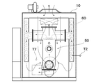
- FIG. 3 is a drawing schematically showing a cross section taken along line II of FIG. 2.
- FIG. 2 schematically shows a cross section of a part of a combustion furnace, a part of an opening / closing door, and a small door. It is a figure which shows the cross section of a heat exchange body typically. It is a figure which shows typically the liquid heating apparatus which concerns on embodiment. It is a figure which shows typically the electric power generation system which concerns on embodiment. It is a figure which shows typically the air conditioning system which concerns on embodiment.
- the control of the combustion amount is accompanied by the control of the supply air amount, but if the air amount is increased or decreased rapidly, incomplete combustion will increase and a large amount of smoke or dust will be emitted. There is a fact. Therefore, there is a problem that in the control of the heat generation amount, the increase / decrease of the supply air must be appropriately controlled and the burner cannot be produced.
- woody fuel The components of woody fuel are cellulose, hemicellulose, lignin, volatile components, trace metals and moisture, but the main combustion component is cellulose, and cellulose molecules (C 12 H 20 O 11 ) are decomposed by combustion. Then, as shown in the formula (I), it becomes carbon dioxide and water vapor (N 2 gas in the air is excluded for simplification).
- Hydrocarbons that burn even at relatively low temperatures are preferentially burned by oxygen contained in cellulose, and carbon that burns at high temperatures tends to be oxidized mainly by supplied air. For this reason, when thermal decomposition of the fuel starts under supply air, the combustion is accelerated by the oxygen contained in the fuel. Further, as the fuel is heated, the combustion is excessive due to the oxygen released by itself and the control of the combustion amount becomes difficult. There is a problem.
- the temperature of flue gas passing through the heat exchanger is cooled to 100 ° C. or lower, and it is possible to recover the heat of condensation of a large amount of water vapor. Dioxins are rapidly cooled to a low temperature in the heat exchanger to suppress recombination.
- the calorific value of the furnace is the sum of all calorific values from primary combustion to quaternary combustion, and condensed sensible heat and flue gas calorific value in the tubular heat exchanger, and it was necessary to find an appropriate method for measuring the combustion amount. If the amount of combustion is increased, there will be problems with the heat limit of the structure such as furnace chambers, reaction ducts, catalysts, heat exchangers, etc. Furthermore, development of a practical combustion system to achieve clean smoke emission is required .
- the flue gas tends to emit smoke, dust, or dioxins, which is a problem as PM2.5, so it needs to be cleaned.
- exhaust from the chimney, exhaust from the chimney, drain (condensed vinegar) that is a condensate generated in the flue, and combustion residue wood ash that is a metal oxide accumulate on the bottom of the furnace.
- the present embodiment can be burned in the cheapest bulk state without consuming energy for processing of the wood-based solid fuel (wood-based bulk fuel), It is another object of the present invention to provide an automatic combustion control method for a wood-based bulk fuel combustion furnace that can change the combustion state freely and effectively use the necessary combustion heat and can easily control the combustion.
- the wood-based bulk fuel boiler provided by this embodiment can use the wood-based bulk fuel dispersed in the region at the lowest cost, and when the operation is facilitated by automatic control, this wood-based bulk fuel boiler is used as a heat source. Therefore, it becomes easy to use a gas heating device, a drying device, a hot water supply device, or the like with high thermal efficiency, and the way to use inexpensive heat energy is opened.
- the boiler is a high-emission, zero-emission combustion method suitable for environmental measures, and it is also required to pioneer the use of pollutants for ashing and the like.
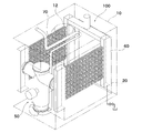
- a solid fuel combustion apparatus 100 includes a combustion furnace 20, a gas supply apparatus 40 for supplying a gas containing oxygen to the combustion furnace 20, and a gas in the combustion furnace 20. And an exhaust device 42 for discharging.
- the gas supply device 40 and the exhaust device 42 are controlled by a control device 46.
- the solid fuel combustion apparatus 100 exhausts the smoke generated in the combustion furnace 20 from the exhaust port 44 through the exhaust passage.
- a reaction duct 50 for burning the smoke generated in the combustion furnace 20, and a heat exchanger 60 for exchanging heat of the smoke discharged from the reaction duct 50 with a gaseous or liquid medium. It has been.
- An opening / closing door 30 for supplying solid fuel to the combustion furnace 20 is provided.
- the combustion furnace 20 is surrounded by the housing 10.
- the heat exchanger 60 exchanges heat with a gas or liquid heat medium supplied into the housing 10.
- the housing 10 can be provided such that a space is created between the housing 10 and a surface other than the front surface of the combustion furnace 20, for example. More specifically, the housing 10 can cover the combustion furnace 20 such that a predetermined space is created between the back surface, the side surface, and the top surface of the combustion furnace 20.
- the combustion furnace 20 burns solid fuel.
- the combustion furnace 20 is supplied with a gas containing oxygen supplied from the gas supply device 40.
- the gas containing oxygen can be supplied from the upper part of the fuel furnace.
- the combustion furnace 20 is provided with an exhaust port 24 for exhausting smoke.
- the discharge port 24 can be provided in the lower part of the combustion furnace 20, for example.
- a gas containing oxygen may be supplied to the combustion furnace 20 from the upper surface side of the combustion furnace 20 by an air supply nozzle.
- the exhaust port 24 for exhausting smoke can be provided, for example, at the lower back side.
- An internal flue 26 can be provided to guide the flue gas in the combustion furnace 20 to the exhaust port 24.
- the internal flue 26 can guide smoke from the upper side of the combustion furnace 20 to the exhaust port 24, for example.
- the internal flue 26 may be configured by providing a partition plate 28 made of heat-resistant steel so as to face the wall surface on the discharge port 24 side. By providing the inlet of the internal flue 26 in the upper part of the combustion furnace 20, the combustion gas component is guided upward, and the combustion gas component is easily burned in the upper part of the combustion furnace 20.
- the combustion furnace 20 includes a fuel supply port 22 for supplying the provided solid fuel and an open / close door 32 provided for closing the fuel supply port 22.
- a sealing member 36 is provided at least around the supply port of the combustion furnace 20 to prevent outside gas from entering.
- the sealing member 36 is provided at a portion to which a pressing force is applied by the opening / closing door 30.
- the sealing member 36 is composed mainly of heat-resistant glass fiber, ceramic fiber, or carbon fiber. When the sealing member 36 is composed of glass fiber, ceramic fiber, or carbon fiber as a main component, the pressing force of the open / close door 30 is weakened when the combustion furnace 20 becomes high pressure, and the glass fiber.
- the opening / closing door 30 is provided on the front side of the housing 10, for example.
- the open / close door 30 can be attached to the combustion furnace 20 by a hinge 38 so as to be openable and closable.
- the open / close door 30 can be provided with a fuel addition port 16 for allowing fuel to be added and a small door 32 for opening and closing the fuel addition port 16.
- the small door 32 can also be attached to the opening / closing door 30 by a hinge 38 so as to be opened and closed.
- the combustion furnace 20 can be made of a general steel plate or a heat-resistant steel plate.
- a plurality of handles 34 for adjusting the tightening pressure of the opening / closing door 30 are provided on both sides of the opening / closing door 30, and the opening / closing door 30 is tightened by the handles 34 to tighten the packing as the sealing member 36.
- a small door 32 that opens and closes the opening is provided with an opening on the upper part of the opening / closing door 30, and similarly to the opening / closing door 30, the tightness of packing as a sealing member 36 provided on the small door 32 can be adjusted by the handle 34. Can be.
- the gas supply device 40 can be, for example, a fan capable of frequency adjustment with a solenoid valve at the outlet.
- the gas supply device 40 can be configured to be able to supply an accurate air volume between a minimum air amount of 0% and a maximum air amount of 100% by a solenoid valve, and in a dormant state in which the combustion of the combustion furnace 20 is stopped, The supply of a minute amount of air that can be maintained is guaranteed, and the air can be completely shut off to extinguish the fire.
- the exhaust device 42 can be, for example, a fan capable of frequency adjustment with a solenoid valve at the outlet.
- the gas supply device 40 and the exhaust device 42 may perform inverter control.
- the control unit 46 detects the temperature by, for example, a temperature sensor and controls the gas supply device 40 and the exhaust device 42. By controlling the gas supply device 40 and the exhaust device 42 in conjunction with each other by the control unit 46, the internal pressure of the combustion furnace can be adjusted.
- the pressure of the combustion furnace 20 is, for example, ⁇ 10 Pa or less, preferably less than ⁇ 10 Pa and in the range of ⁇ 1000 Pa or more, preferably less than ⁇ 10 Pa and in the range of ⁇ 500 Pa or more, more preferably in the range of ⁇ 50 to ⁇ 500 Pa. More preferably, it can be in the range of ⁇ 150 Pa to ⁇ 300 Pa.
- An appropriate value of the furnace pressure can be selected according to the structure and function of the furnace.
- the control unit 46 may be configured by a control panel having a control circuit, or may be configured by a control device 46 including a central processing unit (CPU or the like), ROM, and RAM.
- the control unit 46 may also have a function of controlling each unit of the solid fuel combustion apparatus 100.
- the control unit 46 may control each unit based on the temperatures measured by the temperature sensors T1 to T8.
- the internal pressure of the combustion furnace 20 By controlling the internal pressure of the combustion furnace 20 to ⁇ 10 Pa or less, combustion is promoted at a low temperature and is easily controlled. Further, when there is a fuel addition port for adding solid fuel during combustion, when the fuel addition port 16 is opened, it is possible to prevent flue gas and dust from jumping out from the combustion furnace 20.
- the pressure is -10 Pa or less, no pressure is applied to the outside, and therefore the open / close door 30 that closes the large fuel supply port can be provided without using a thick and large steel material.
- the open / close door 30 is provided because the furnace pressure of the combustion furnace 20 is a negative pressure, it is not necessary to use a sturdy fixture. Solid fuel can be supplied sequentially and safely, and fuel can be continuously supplied.
- the temperature in the combustion furnace 20 By controlling the gas supply device 40 and the exhaust device 42 in conjunction with the controller 46, the temperature in the combustion furnace 20, the degree of oxidizing atmosphere, and the combustion of the solid fuel can be controlled.
- the smoke emission temperature at the discharge port 24 of the combustion furnace 20 can be 500 ° C. or less, preferably 400 ° C. or less, more preferably 200 to 400 ° C.
- the combustion of the solid fuel it is possible to prevent the solid fuel from burning at once.
- the solid fuel combustion apparatus 100 generally has a structure in which air is taken in from an air intake and the smoke is discharged by a chimney discharge function.
- a supply device for supplying air such as a blower, a discharge device for discharging smoke exhaust to the outside, or a bag filter, a swiveling device for collecting dust from the exhaust smoke, and A cyclone dust collector may be provided.
- a blower a discharge device for discharging smoke exhaust to the outside
- a bag filter a swiveling device for collecting dust from the exhaust smoke
- a cyclone dust collector may be provided.
- there has been no idea of controlling the combustion of the solid fuel by linking the air supply device and the smoke emission device to make the furnace pressure negative.
- the inventor can easily control the combustion of the solid fuel by including the control unit 46 that controls the furnace pressure of the combustion furnace 20 by linking the gas supply device and the exhaust device 42. I found.
- the temperature in the combustion furnace 20 can be controlled under reduced pressure, the temperature does not become high, so that damage to the combustion furnace 20 can be suppressed. Further, when the combustion furnace 20 is made of a chromium-based material, hexavalent chromium tends to be generated when the temperature exceeds 1000 ° C. However, since the temperature of the combustion furnace 20 can be controlled to 1000 ° C. or lower, There will be no problems that occur. In general, in the case of biomass fuel, the temperature in the combustion furnace 20 is often increased to 1000 to 1100 ° C. in order to approach the condition of complete combustion.
- the degree of the oxidizing atmosphere can be easily controlled, reduction of chromium that occurs under reduction when the combustion furnace 20 is made of a chromium-based material can be suppressed, and hexavalent chromium. Can be surely prevented.
- the reaction duct 50 is for completely burning the flue gas. Since the flue gas can be burned by the reaction duct 50, the flue gas of incomplete combustion can be burnt completely easily.
- the reaction duct 50 can be provided with, for example, a first smoke combustion section 52, a second smoke combustion section 54, and a third smoke combustion section 56.
- the reaction duct 50 can be made of a heat resistant steel plate. When the reaction duct 50 and the combustion furnace 20 are made of different materials, the thermal expansion is different. Therefore, the connection part between the reaction duct 50 and the combustion furnace 20 is connected to each other with a flexible structure so that large expansion and contraction due to heat can be freely made. Can be absorbed.
- the first flue gas combustion section 52 is for burning flue gas by mixing flue gas and gas containing oxygen using ignition means such as a burner as a fire type.
- the gas containing oxygen is supplied from the oxygen supply path 70.
- the oxygen supply path 70 can be provided so as to pass through the combustion furnace 20. Thereby, oxygen passing through the oxygen supply path 70 can be heated in the combustion furnace 20.
- the oxygen supply path 70 is connected to the gas supply device 40, and a conduction hole 72 is provided in the oxygen supply path 70 in the combustion furnace 20, and a part of the oxygen-containing gas in the oxygen supply path 70 passes through the conduction hole 72.
- a gas containing oxygen that is supplied to the combustion furnace 20 and not supplied to the combustion furnace 20 may pass through the oxygen supply path 70 and be mixed with the flue gas.
- the 1st flue gas combustion part 52 may induce the fire of the combustion means applied with the 2nd flue gas combustion part 54, and may burn flue gas.
- the temperature of the flue gas in the first flue gas combustion unit 52 can be, for example, in the range of 200 to 600 ° C., more preferably 250 to 500 ° C.
- a tip 74 of the oxygen supply path 70 is formed into a nozzle shape, and a gas containing oxygen can be discharged from the tip 74 to the first flue gas combustion unit 52 and mixed with flue gas containing unburned components.
- the oxygen supply path 70 can be provided so as to pass through the upper part in the combustion furnace 20, and the conduction hole 72 of the oxygen supply path 70 can be provided in the upper part in the combustion furnace 20.
- the combustion component rises upward, so that it is preferable to burn in the upper part of the combustion furnace 20.
- the oxygen supply path 70 is above the combustion furnace 20, the gas containing oxygen in the oxygen supply path 70 is easily heated by the heat generated in the combustion furnace 20.
- the gas containing oxygen in the oxygen supply path 70 is heated by the heat of the combustion furnace 20.
- the gas containing oxygen when the gas is mixed with the flue gas and burned, the combustion is further promoted and the flue gas is easily burned.
- the combustion component rises upward, so that it is preferable to burn in the upper part of the combustion furnace 20. For this reason, since the oxygen supply path 70 is above the combustion furnace 20, the gas containing oxygen in the oxygen supply path 70 is easily heated by the heat generated in the combustion furnace 20.
- the second flue gas combustion unit 54 is for burning the flue gas remaining in the first flue gas combustion unit 52 by a combustion means such as a burner.
- the temperature of the flue gas in the second flue gas combustion unit 54 can be set to 600 to 1000 ° C., for example. By burning the flue gas with a burner, the temperature of the flue gas usually rises to 800-900 ° C. For this reason, dioxins can be decomposed easily.
- the third flue gas combustion part 56 can be composed of a catalyst part for further promoting oxidation of the flue gas components.
- the catalyst portion may be a honeycomb-type ceramics composed mainly of an alkaline earth metal oxide.
- the catalyst portion is preferably a ceramic that can be used at 300 ° C. or higher, preferably 1000 ° C.
- the catalyst portion can be configured to be placed in an oxidizing atmosphere during combustion and have a temperature in the range of 300 to 1000 ° C., for example.
- An oxidizing atmosphere can be realized by controlling the gas supply device 40 and the exhaust device 42 to increase the supply amount of a gas containing oxygen.
- dioxins can be decomposed.
- the chemical component of the oxidation catalyst suitable for the purpose is, for example, CaOSiO 2 , CaOAl 2 O 3 , or MgOAl 2 O 3 , and their melting points are 1540 ° C., 1600 ° C., and 2135 ° C., respectively. These practical maximum temperatures are 900 ° C., 1000 ° C., and 1100 ° C., respectively. Both can be obtained by molding an equivalent mixture of unit CaO, SiO 2 , MgO, or Al 2 O 3 and then sintering at a high temperature in an oxidizing atmosphere. Since the sintering temperature depends on the particle size of the raw material used, it does not need to be specified, but it should be higher by 200 ° C. to 400 ° C. than the practical temperature.
- the chemical components of these oxidation catalysts do not need to be limited to the above three types, and can be composed of mixed components, and some metal oxides such as SiO 2 can be used as a sintering aid. It can contain extra things.
- Smoke is oxidized by a direct chemical reaction in the honeycomb type space surrounded by the surfaces or walls of these oxidation catalysts, so there is no need to use expensive precious metals such as Pt or Pd.
- precious metals such as Pt or Pd.
- the use of these noble metals for catalytic activity is disadvantageous because of high consumption due to oxidation and evaporation at high temperatures and chemical reactions.
- the reaction duct 50 capable of performing effective flue gas treatment at a temperature of 300 ° C. or higher to 1000 ° C. by the heat of the fourth combustion in the third flue gas combustion unit 56 can be realized.
- the heat exchanger 60 a large amount of water vapor contained in the flue gas is condensed by exchanging heat with the heat medium to generate heat of condensation. Condensed water is collected.
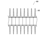
- the heat exchanger 60 is formed of, for example, a tubular heat exchanger, and fins 62 can be provided as shown in FIG. 5 in order to increase the surface area.
- the smoke emission temperature at the inlet of the heat exchanger 60 can be set to 500 to 700 ° C. or less, for example.
- the smoke emission temperature at the outlet of the heat exchanger 60 can be set to 200 ° C. or less, for example.
- the water condensed in the heat exchanger 60 moves inside the heat exchanger 60 and is discharged to the outside.
- the heat exchanger 60 may be on the side of the combustion furnace 20 or on the top of the combustion furnace 20.
- the heat exchanging body 60 may be provided horizontally, or may be provided so as to go down as it goes to the exhaust port 44 side. By providing the heat exchanger 60 so as to go down toward the exhaust port 44, the condensed water generated in the heat exchanger 60 can be reliably guided to the exhaust port 44.
- the water vapor contained in the flue gas is condensed, and the heat generated by the condensation is transferred to a liquid or gaseous medium, so that the heat generated in the condensation can be used effectively. Combustion efficiency can be increased.
- water vapor in the flue gas is exhausted without being recovered.
- fever of a flue gas transfers to the liquid or gaseous heat medium through the heat exchanger 60, the temperature of flue gas becomes low. For this reason, damage to the exhaust path such as a chimney can be suppressed.
- the water vapor is condensed, the water vapor contained in the flue gas is reduced, and accordingly, damage to the exhaust passage due to the water vapor can be suppressed.
- the temperature of the exhaust gas can be lowered.
- the flue gas at 700 ° C. is rapidly cooled to 200 ° C. or less at the entrance of the condensing unit composed of the heat exchanger 60 to effectively prevent recombination of decomposed dioxins. it can.
- the solid fuel combustion apparatus 100 may be provided with thermometers T1 to T8 for measuring temperatures at various places.
- the thermometer can be composed of a temperature sensor such as a thermocouple.
- the temperature to be measured includes, for example, the temperature near the ceiling of the combustion furnace 20, the temperature near the exhaust port 24 where the smoke is discharged from the combustion furnace 20, the temperature near the second flue gas combustion unit 54, a burner, and the like. Examples thereof include temperature and catalyst temperature.
- the combustion in the combustion furnace 20 is “primary combustion”, the combustion in the first flue gas combustion part 52 is “secondary combustion”, the combustion in the second flue gas combustion part 54 is “third combustion”, and the third Combustion in the flue gas combustion unit 56 is defined as “quaternary combustion”, and each term is used in this specification.
- an object of the present inventor is to provide an automatic combustion control system for a wood-based bulk fuel boiler that is easy for anyone to use.
- a total of eight temperature sensors T1 ⁇ T8 is installed to provide a method for clean burning of wood-based bulk fuel, which is a solid fuel.
- the intake of the heat medium (for example, heating air) is provided. It is a sensor for measuring the temperature of.
- the second temperature sensor T2 is, for example, a heat medium (for example, heated) that is heated directly below the heat exchanger 60 provided between the casing and the casing that covers the hot air passage that is the space on the side surface of the combustion furnace 20. Air).
- the third temperature sensor T3 is a sensor that measures the temperature of the center of the ceiling in the combustion furnace 20, for example.
- the fourth temperature sensor T4 is a sensor that measures the temperature in the vicinity of the burner, for example.
- the fifth temperature sensor T5 is a sensor for measuring the temperature immediately above the catalyst.
- the sixth temperature sensor T ⁇ b> 6 is a sensor that measures the temperature of the outlet 24 of the hot air blower 80.
- the seventh temperature sensor T7 is a sensor that measures the temperature in the greenhouse to which hot air is to be supplied.
- the eighth temperature sensor T8 is an outside air thermometer.
- the total heat generation amount is controlled by increasing or decreasing the amount of air supply determined by the relationship between the gas supply device 40 and the exhaust device 42.
- the maximum allowable amount of combustion is the ceiling temperature T3, burner temperature T4, and catalyst temperature T5 in the furnace chamber It can be controlled automatically.
- control of the combustion amount is important for the operation of the combustion furnace 20, and the calorific value thereof includes all calorific values from primary combustion to quaternary combustion, and condensed sensible heat in the heat exchanger 60. And the total amount of heat that the flue gas has.
- the primary combustion heat of the combustion furnace 20 the secondary combustion of the reaction duct 50, the tertiary combustion by the auxiliary combustion burner, the quaternary combustion by the oxidation catalyst and the heat exchanger It has been found that the hot air temperature T2 obtained at a position designated directly below the tubular heat exchanger in the flue passing through 60 can be used as a factor representing the combustion amount.
- the boiler flue gas that burns biomass is required to be clean because it contains soot and particulate PM2.5, pitches, dioxins, and the like.
- secondary combustion first smoke combustion unit 52
- second smoke combustion unit 54 tertiary combustion
- third flue gas combustion unit 56 a method of obtaining clean flue gas through the system of quaternary combustion
- an efficient usage method is preferable from the standpoint of use.
- two methods can be used depending on the usage mode.
- One method is a batch type, in which a large amount of fuel is injected into the combustion furnace 20 at a time. In a typical example, fuel is consumed for 5 days, and then the furnace temperature is lowered and new fuel is injected. This is a method of restarting the combustion operation by a one-week cycle.
- the second method is a replenishment type, in which a desired amount of fuel is introduced into the furnace chamber from the small door 32 or automatic inlet in accordance with a shortage of fuel during the combustion operation. This is a method in which the fuel is replenished on the next day and the combustion operation can be repeated in a one-day cycle.
- the wood ash that accumulates in the bottom of the furnace can be used continuously by removing it once every six months.
- Control technology In the combustion furnace 20 using wood and wood-based bulk fuel or carbide as fuel (hereinafter referred to as wood bulk fuel boiler), it can be used as the cheapest fuel without processing logs or wood stocks. In order to prevent environmental pollution due to incomplete combustion, the following basic combustion control technology can be used.
- Patent Document 4 the basic structure of a wood-based bulk fuel boiler and the accompanying combustion control method are disclosed in Patent Document 4 described above by the present inventor.
- manual operation of the bulk fuel boiler has many problems and requires considerable skill.
- the reason for this is that the combustion temperature, combustion speed, smoke emission, etc. are affected by differences in tree species such as cypress, cedar, larch, and bamboo, fuel thickness and shape, and moisture content (dryness).
- the combustion control conditions are different. Therefore, considerable skill is required to perform the furnace combustion control manually, and an automatic operation control function that anyone can easily operate is required.
- Igniting a non-combustible bulk fuel from a wood-based bulk fuel, such as firewood expands its combustion range due to a flame that emits smoke. If there is fuel where it is directly heated by the flame, the unburned part receives the heat of combustion and the flame further expands, but as a feature of the bulk fuel boiler, combustion is directed downward from the top of the fuel, The combustion heat from the flame heats and ignites the surrounding fuel, but the temperature of the fuel underneath rises little, and the temperature rises slightly and the drying proceeds. At the beginning of combustion, hydrogen and light hydrocarbons are first burned with flames, followed by bonfire combustion centering on carbonized parts and charcoal fire, and finally wood ash remains.
- Initial mode refers to the work of igniting the fuel after the fuel is charged and the device is checked. Ignition work is either automatic or manual work, but for simplicity, the basic manual work will be used for explanation. Generally, there are many fuels that are difficult to ignite, such as logs, driftwood, sawn timber, wood stocks, etc., which are put into the furnace. Therefore, a flammable brazing material is placed in front of the center of the top of the fuel and ignited. As a brazing material, if you use extinguisher as the brazing material, it can be ignited very easily and reliably. Extinguishing charcoal can be obtained in large quantities when the furnace is extinguished a little earlier, rather than having the furnace run to the end and burning it completely to make only wood ash.
- the large door of the furnace chamber is opened, the auxiliary burner is ignited, and the gas supply device 40 (air supply fan), solenoid valve, and exhaust device 42 (induction fan) are driven at the maximum capacity.
- the gas supply device 40 air supply fan
- solenoid valve solenoid valve
- exhaust device 42 induction fan
- the burner ignition, the gas supply device 40, the solenoid valve, the induction fan, etc. are driven according to the set values set by the programmable controller, and the operation of checking the fuel ignition and closing the large door is a manual operation. .
- the combustion state is usually greatly different depending on the ignition state, and it is necessary to realize a calm combustion state before shifting to the automatic control.
- the small door 32 is opened, it can be seen that the inside of the furnace is filled with smoke, the furnace pressure is negative, and it is normal that the smoke does not blow out from the small door 32. After a while, it can be seen that a large flame is generated by the air sucked from the small door 32.
- the state in which smoke is ejected from the small door 32 to the outside of the furnace is an overcombustion state, and it is necessary to immediately close the small door 32 to avoid inflow of air and to lower the opening of the solenoid valve.
- the solenoid valve of the gas supply device 40 is preferably closed to 30% to 60%, more preferably 40% to 50% and maintained for 10 minutes to 60 minutes. More preferably, by maintaining for 30 to 40 minutes, the combustion state due to the difference in fuel quality and (1) the difference in fuel ignition in the initial mode is adjusted.
- the exhaust device 42 is maintained at 40 Hz to 50 Hz, and the furnace pressure is ⁇ 10 Pa or less, preferably less than ⁇ 10 Pa and in the range of ⁇ 1000 Pa or more, more preferably less than ⁇ 10 Pa and ⁇ 500 Pa or more.
- the amount of combustion is adjusted by an electromagnetic valve for the deviation of the hot air temperature T2, but as a feature of the wood fuel boiler, the heat capacity of the combustion furnace 20 as a whole is large, and the temperature of the fuel increases with combustion and the oxygen released from the fuel Because of this, self-combustion proceeds, and there is a problem that overcombustion is likely to occur.
- the hot air temperature T2, and thus the hot air temperature T5 becomes higher than the set value, and the catalyst temperature T4 and the temperature T3 in the combustion furnace 20 also become higher.
- a gentle opening / closing speed is used to suppress smoke generation due to a rapid opening / closing operation of the solenoid valve, and an appropriate opening / closing speed is 1% to 1% per minute. 10%, more preferably 4% to 6%.
- the hot air temperature T2 starts to rise, and usually the hot air temperature T5 also rises a little later.
- the set value of the hot air temperature T5 varies depending on the season and application, and is usually 20 ° C to 60 ° C.
- the maximum temperature is the hot air blower (hot air fan) 80 or plastic.
- the heat resistance limit of the duct is 60 ° C.
- the maximum heating capacity that is the difference between the temperature T1 of the air intake and the warm air temperature T5 of the warm air output is approximately ⁇ T to 50 ° C.
- the air volume can be reduced when a high hot air temperature is required for a constant heat output, and the air volume can be increased at a low hot air temperature. Since the hot air blower 80 is driven by an inverter, the air volume can be easily changed mechanically. However, since the change in the air volume of the hot air blower 80 impairs the combustion stability of the combustion furnace 20, that is, the thermal equilibrium state, stable combustion is possible. In order to maintain the state and the fuel output, it is good to limit the change to at most once per hour.
- a warm air temperature of 90 to 120 ° C. may be used for use as a dryer.
- a hot air blower 80 having a heat resistance limit of 180 ° C. or higher is used.
- the high-temperature return hot air 50 ° C to 60 ° C used is taken into the air intake and is heated to supply a maximum of 100 ° C to 110 ° C hot air. Will be reduced to 50% or less.
- the warm air temperature When dry fuel (water content around 20%) is used, the warm air temperature often reaches the set value in about 2 hours after the fuel is ignited. With a humid fuel (moisture content of 30% to 40%), depending on the tree species and quality, it often takes time to raise the temperature of the combustion furnace 20, and 5 hours to 10 hours for the hot air temperature T2 to rise sufficiently. It may take time. However, once warming is performed, heating in the re-flamming mode after the next time can normally be raised or lowered in about one hour. Further, in the case of humid fuel, the amount of drain discharged from the heat exchanger may exceed 100 liters per day.
- the time zone for the combustion process is substantially the steady mode 1/3, the transition mode 1/3, and the bonfire mode 1/3.
- the combustion of the carbon component is the main and the combustion of the hydrogen content is reduced, so carbon dioxide is generated, but oxygen twice the hydrogen component is required.
- the supply capacity of the combustion system requires an oxygen supply capacity that is approximately twice that of the steady mode, and in order to obtain a heat quantity equivalent to that of the steady combustion mode, the supply amount of the gas supply device 40 is greatly increased. It turned out that it can be solved by doubling or doubling.
- the operation of the combustion furnace 20 has various usages such as continuous operation and temporary suspension.
- 24-hour heating such as in a dryer or cold district
- heating is used during the daytime, such as in factories, meetinghouses, offices, etc. It is necessary to pause the combustion depending on the application, such as when it is used, and to restart the combustion if necessary.
- the burning combustion furnace 20 is temporarily stopped according to the program to be put to sleep, and then burned again according to the program at a desired time.
- the electromagnetic valve for supply can be adjusted to 1% to 10%, preferably 3% to about 7%.
- the air supply amount is greatly reduced to preserve the seed fire in the burnt burnt wood pile or in the charcoal buried in wood ash. Can do. After the transition to the sleep mode, ignition of the burner is stopped, but the burner fan is driven to prevent contamination of the nozzle portion.
- the amount of the seed fire depends on the opening of the solenoid valve and the combustion state, it is necessary if necessary to adjust the rise time at the time of reburning. If the opening at the time of dormancy is low, the consumption of fuel during dormancy is small, but the rise time at the time of reburning may be long.
- reheating is performed at the programmed time, and the heat output of the combustion furnace 20 can be increased.
- a rapid increase in thermal power is required, but after the combustion operation, the fuel is dry and ignition and temperature rise are easy.
- a reheating mode in which the combustion furnace 20 is continuously operated while adding fuel. If the exhaustion of fuel progresses and the amount of heat is insufficient, the hot air temperature T2 will not increase even if the air supply amount is increased to 100%. Therefore, after detecting the fuel shortage, the mode is changed to the reheating mode or the fire extinguishing mode. Become. After shifting to a refueling mode that extends the combustion time, refueling fuel can be added.
- the general combustion method is to add fuel continuously and continuously.
- a wood bulk fuel furnace has a feature that the additional amount, that is, the amount of fuel replenishment, can be set to about one day.
- the amount of refueling depends on the quality of the fuel used, but it is possible to grasp the daily amount from the fuel used.
- a reheating amount generally 1/5 to 1/7 of the batch amount, is charged into the combustion furnace 20 from the small door 32 or the automatic charging port.
- the mode is switched to the fire extinguishing mode manually or at a programmed time, and the solenoid valve is sequentially reduced from the use state to 0%. After reducing the rotation speed to about 10 Hz, the fire in the combustion furnace 20 can be extinguished completely. Although it cannot be avoided with a boiler having a large heat capacity, it is required to cool 20 heated combustion furnaces in a short time.
- the entire combustion furnace 20 can be cooled by operating the hot air blower 80, so the hot air blower 80 is driven at 50 to 60 Hz for 2 to 4 hours, and more preferably. By driving for about 3 hours, it is possible to stop after the hot air temperature T2 becomes approximately 25 ° C. or less (when the outside air temperature is 10 ° C.).
- the control conditions and control method for each combustion mode in the combustion control described above can be realized by using an electronic control device for a factory automation system.
- the main electrical components for automatic control are equipped with a combustion control software program in a high-performance programmable controller, a serial communication unit that connects to operating equipment at high speed, and an analog output unit and temperature that must be properly used in the control equipment. Use the sensor unit. Moreover, the operation status of these control systems can be confirmed and the operation status can be displayed on the touch panel.
- the air volume or rotational speed of the exhaust device 42 that adjusts the amount of smoke exhausted and the warm air blower 80 that adjusts the amount of supplied heat correspond to each other by automatically adjusting the heat generation amount, the hot air temperature, and the air volume by inverter control.
- the mixing damper 14 the outside air T1 and hot air T2 sucked by the electric switch are mixed to obtain hot air of the target hot air temperature T6.
- the solenoid valve of the gas supply device 40 is preferably closed to 30% to 60%, more preferably 40% to 50%, and it is preferably maintained for 10 minutes to 60 minutes, more preferably 30 minutes to By maintaining for 40 minutes, the combustion state due to the difference in fuel quality and (1) the difference in fuel ignition in the initial mode is adjusted.
- the exhaust device 42 is maintained at 40 Hz to 50 Hz, and the furnace pressure is set to ⁇ 10 Pa or less, preferably ⁇ 500 to ⁇ 50 Pa, more preferably ⁇ 300 to ⁇ 150 Pa.
- An automatic combustion control method is characterized in that the negative pressure in the furnace is maintained and combustion of the fuel is enabled at a low temperature, and the solenoid valve is automatically adjusted so that the generated hot air temperature T2 achieves a set value. .
- overcombustion that reaches the upper limit temperature of the furnace chamber temperature T3 due to primary combustion or the upper limit temperature T5 of the catalyst for quaternary combustion still occurs due to differences in fuel quality, the state of fuel incorporation in the furnace, or other factors. There is a case.
- the opening of the solenoid valve is reduced at an appropriate opening / closing speed.
- sudden opening / closing increases smoke generation, so gentle opening / closing is necessary, and it should be 1-10% per minute. More desirably, slow opening / closing at 4 to 6% is required.
- the combustion is mainly made of carbides and charcoal, so the combustion of hydrocarbons is small and the combustion of carbons is the main, so there is little smoke but a large amount of oxygen is required.
- the air volume had to be 1.5 to 2.5 times that of the steady mode.
- the charcoal fire burns in the bonfire mode, the furnace temperature tends to increase, and the heat resistance of the furnace chamber is required. As a result, flue gas accumulated in the furnace chamber and flue and dirt on the pitches are completely burned and cleaned, and the bonfire mode enables combustion of coals that have the same combustion conditions as coal.
- the air supply solenoid valve In the dormant mode, it is better to adjust the air supply solenoid valve to 1% to 10% at the programmed time, preferably 3% to about 7% to greatly reduce the air supply amount. It was found that it was possible to preserve the seed fire inside the burnt burnt wood pile or in a charcoal fire buried in wood ash. The fire could be maintained for as long as there was fuel, and could be re-burned at the desired time as needed.
- the process is to release the dormant mode and switch to the steady mode at the programmed time to reburn the fuel. If the amount of the seed fire is appropriate, the time required to reheat is 1 ⁇ 2 hours.
- the control system In the reheating mode, when the fuel consumption is advanced and the calorific value is reduced, a sufficient amount of reheating fuel is supplied to maintain the heating capability.
- the control system In order to operate the chasing mode safely, the control system is first switched to the sleep mode, and after 20 to 40 minutes have passed, preferably after about 30 minutes have passed, the thermal power has subsided, and from the small door 32 or automatically After adding additional fuel into the furnace from the inlet, it is switched to the reburning mode.
- the amount of fuel that can be input at one time needs to be limited in order to maintain stable combustion.
- the fire type is at the bottom of the replenished fuel that has been added, and it is necessary to keep the amount of combustion for 10 hours or less than one day in order to avoid burning a large amount of fuel at one time. it can.
- the fire-extinguishing mode is used in all combustion modes, either manually or at a programmed time, to close the solenoid valve from use to 0% and further reduce the speed of the exhaust system 42 to about 10 Hz to reduce the fire in the furnace. Can be completely erased.
- the hot air blower 80 is preferably driven at 50 Hz to 60 Hz for 2 hours to 4 hours, and more preferably after about 3 hours of driving, the temperature of the furnace body is lowered. Stop.
- V In the combustion furnace 20 that burns solid fuel such as a wood-based bulk, a method of operating or using the characteristics is provided.
- a batch-type operation method in which a large amount of fuel is put into the combustion furnace 20 at a time, and after the fuel is consumed, the large door of the furnace chamber is opened and new fuel is injected to restart the combustion operation. If there is a shortage of fuel due to fuel consumption on the way, about 1 day of fuel is injected from the inlet or automatic inlet, and the combustion operation is performed in the reheating mode, and the next day is newly input and the combustion operation is repeated. It is possible to use a method using a reheating method, and the wood ash accumulated in the furnace bottom can be removed after a long period of use and can be used continuously.
- clean smoke emission can be obtained by the low-temperature combustion method and smoke emission purification method of solid fuel.
- the amount of dust is about 1/50 that of a typical pellet boiler, and can greatly contribute to measures against PM2.5.
- biomass combustion the occurrence of dioxins can often not be ignored, but in this embodiment, the generation of dioxins can be suppressed.
- the fuel when the fuel is wood fuel, it can be burned if the water content is 40% or less, preferably 30% or less. In addition, even a tree having a high moisture content just cut can be burned if used as part of the fuel. Generally, it is said that the moisture content of firewood in firewood boilers is about 20%, and pellets are about 10%.
- V Generally, there is an exhaust fan that exhausts smoke from the combustion furnace 20, but there is no idea of using the exhaust fan to control the pressure in the combustion furnace 20 to a negative pressure and using a low combustion temperature. .
- combustion control can be performed so that the solid fuel can be burned gradually.
- a platinum-based catalyst Since a platinum-based catalyst is not used, high heat can be generated in the catalyst portion. A platinum-based catalyst is difficult to use for a long time at 300 ° C. or higher because platinum is oxidized or vaporized at 300 ° C. or higher. However, according to the present embodiment, since it is a metal oxide ceramic catalyst, it can be easily used for a long time even at 400 to 1000 ° C.
- the exhaust gas of the incomplete combustion generated in the combustion furnace 20 can be surely completely burned in the duct, and dust can be reduced.
- problems such as backfire due to incomplete combustion hardly occur. For this reason, it was not recognized that an explosion-proof valve was required.
- This embodiment applies an automatic combustion control method that can be used by anyone to a furnace capable of burning wood-based bulk fuel and carbide fuel in the most inexpensive state and using the boiler with high thermal efficiency. be able to.
- This facilitates the use of a clean combustion system that can suppress the generation of soot and dioxins, and has the advantage that it can be easily operated using a batch or reheating system, using fossil fuels. It is expected to be used as a heat energy source to replace oil-based fuel boilers and gas fuel boilers.
- the boiler can be expected to be used in a wide range of fields such as factories, dryers, facility horticulture, animal husbandry, and heating of assembly facilities.
- Gas Heating Device 200 can be realized by using the solid fuel combustion device 100 according to the embodiment. For example, outside air is taken in from the first opening 12 communicating with the hot air passage in a part of the ceiling center of the casing, or circulating air is used as the outer wall of the combustion furnace 20, the heat exchanger 60, and the outer wall of the reaction duct 50. Heat can be generated through heat exchange. A passage is provided so that the hot air can be sucked into the hot air blower 80, and in order to set the temperature of the hot air sucked into the hot air blower 80 to a predetermined hot air temperature, a part of the housing 10 communicates with the hot air passage.
- a predetermined hot air temperature can be obtained by a mixing mechanism that takes in outside air by opening and closing the two openings 14. Thereby, it can comprise so that the warm air of predetermined temperature can be discharged
- guide plates are provided on both sides between the casing 10 and the combustion furnace 20 so that the air contacts the reaction duct 50 when air is taken in from the first opening 12. Can be provided.
- the gas heating device 200 includes a gas supply device 40 and an exhaust device 42 that adjust the internal pressure of the combustion furnace 20 and the flue gas flow velocity in the flue, a mixing damper 14 that adjusts the temperature of hot air by taking in outside air, and a supply amount of hot air
- a warm air blower (such as a warm air fan) 80 to be adjusted is used.
- the hot air blower 80 can be inverter-controlled.
- the mixing damper 14 can use an electric switch or a fan for taking in low temperature outside air.
- the outside air sucked from above the combustion furnace 20 can be divided into two by a damper provided between the furnace ceiling and the furnace top outer wall.
- a part of the outside air is heated via the outer peripheral part of the combustion furnace 20 and the heat exchanger 60 to become hot air, and the other part is heated by exchanging heat with the outer peripheral part of the reaction duct 50 to become hot air.
- the hot air is mixed with the outside air from the outside air intake damper 14 to become warm air at an appropriate temperature, and is sent out by the hot air blower 80.
- This gas heating device 200 is a combustion system suitable for environmental measures, such as primary combustion in which fuel is burned at a low temperature in a negative pressure furnace chamber, secondary combustion for purifying flue gas, tertiary combustion with auxiliary fuel, and A clean combustion system is obtained through quaternary combustion using a strong oxidation catalyst.
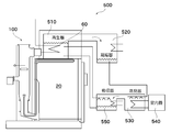
- the solid fuel combustion device 100 can also be applied to the liquid heating device 300.
- a liquid (such as water) is taken from the first opening 12 of the casing 10 and the like, and the liquid is circulated in the housing 10 so that the outer wall of the combustion furnace 20, the heat exchanger 60, the outer wall of the reaction duct 50, and the like
- the liquid can be heated by heat exchange.
- the liquid can be introduced into the housing 10 through the conduit, but the first opening 12 and an inlet for entering the conduit into the housing 10 are provided on the upper surface or the side surface of the housing 10. Also good.
- the heated liquid may be discharged to the outside with a pump or the like, and the heated liquid may be used for any purpose, or may be radiated by a heat radiating unit and used to heat any object such as a heat medium. .
- a tank 310 is provided on the combustion furnace 20, and the heat of the combustion furnace can directly heat the liquid in the tank, and further, smoke is exhausted in the tank 310.
- a heat exchanger 60 passing therethrough can be provided, and the heat of the smoke can be heated by the heat exchanger 60 as a liquid heat medium.
- a cistern 320 can be connected to the tank 310. When the temperature of the water increases and the pressure of the liquid in the tank 310 increases, the liquid moves to the cistern 320 until the pressure in the tank 310 reaches normal pressure. When the pressure of the liquid is lower than the normal pressure, the liquid returns from the cistern 320 to the tank 310 and is supplied until the water in the tank 310 reaches the normal pressure. Further, as necessary, the heated liquid may be discharged from the tank 310 or the liquid may be supplied to the hot water storage tank.
- the flue gas flue is configured so that the heat exchanger 60 passes through the evaporator 410.
- a liquid heat medium (for example, water) is stored in the evaporator 410.
- the heat of the smoke is transferred to the liquid heat medium by the heat exchanger 60.
- the evaporator 410 can be provided on the combustion furnace 20, for example. Thereby, the heat of the combustion furnace 20 can be transferred to the liquid heat medium in the evaporator 410 through the upper surface of the combustion furnace 20.
- the heat of the smoke is transferred from the heat exchanger 60 to the liquid heat medium, so that the liquid heat medium evaporates.
- the gaseous heat medium can be supplied to an expander 420 serving as a turbine, and the energy of the gaseous heat medium can be converted into rotational energy by the expander 420 and can be generated by the generator 430.
- the heat medium discharged from the expander 420 is condensed into a liquid in the condenser 440, and the condensed liquid heat medium returns to the evaporator 60.
- the expander 420 for example, a semi-sealed screw turbine type generator in which a screw turbine and a generator are integrated in a single shaft can be used.
- Cooling System 500 using the solid fuel combustion apparatus 100 according to the embodiment will be described with reference to FIG.
- the flue gas flue is configured so that the heat exchanger 60 passes through the regenerator 510.
- a liquid heat medium for example, water
- the heat of the smoke can be transferred to a liquid heat medium by the heat exchanger 60.
- the regenerator 510 can be provided on the combustion furnace 20, for example. Thereby, the heat of the combustion furnace 20 can be transferred to the liquid in the regenerator 510 through the upper surface of the combustion furnace 20.
- the first heat medium for example, water
- the heat exchange element 60 transfers the heat of the smoke to the first heat medium (for example, water), and the first heat medium evaporates.
- the first heat medium is condensed in the condenser 520.
- the condensed first heat medium is supplied to the decompressed evaporator 530 and is evaporated by the evaporator 530.
- the first heat medium absorbs evaporation heat from the second heat medium circulating between the first heat medium and the indoor unit in the heat exchanger.
- the cooled second heat medium is supplied to the indoor unit 540.
- the first heat medium is absorbed by the solution that absorbs the first heat medium in the absorber 550.
- the solution that absorbs the second heat medium returns to the regenerator 510 by a pump or the like.
- combustion device A and combustion device B were manufactured as the solid fuel combustion device according to this example, and the automatic combustion control function was verified.
- the important elements in the combustion control are the combustion furnace body structure, the combustion function, and the control function, which are the size of the combustion furnace shown in Table 2, the capabilities of the gas supply device and the exhaust device, and the hot air blower.
- the size of the combustion furnace is an important factor depending on the application because it directly limits the amount of fuel that can be fed in batch mode.
- Fuel is injected into a combustion furnace of 2 m 3 in the combustion furnace of the combustion apparatus A and 4 m 3 in the combustion furnace of the combustion apparatus B.
- the amount of fuel that can be input varies greatly depending on the shape of the fuel. Even if large and small logs are introduced so as to reduce the gap, A is at most 1 t, and B is about 2 t.
- Combustion that is, the amount of heat generated
- the air blowing capacity depends on the structure and performance of the fan. It can be said that it is proportional to the magnitude of electric power.
- Table 2 shows power consumption as a method for briefly indicating the functions of the fans.
- auxiliary burner In the combustion furnace, smoke is generated by incomplete combustion due to primary combustion, and unburned components are further combusted by secondary combustion, but combustion is further promoted by an auxiliary burner.
- a kind of fossil fuel kerosene or gas can be used for the auxiliary burner.
- An electric heater can be used as a simple method, but kerosene can be used as a result of cost effectiveness.
- a 1.5 L burner was used as the kerosene usage fee per hour, the calorific value is equivalent to 15.3 kWh / h. Accordingly, the calorific value of the combustion furnace becomes the sum of the calorific value of the wood fuel and the calorific value of the burner. Therefore, in the combustion furnace of the combustion apparatus A and the combustion furnace of the combustion apparatus B, 18.8% and 10.
- the combustion furnace of the combustion apparatus A and the combustion furnace of the combustion apparatus B are used, and as described in the above embodiment, (1) the initial mode in which the fuel needs to be ignited; Steady mode that burns with flame, (3) Bonfire mode in which carbide of combustion residue burns, (4) Dormant mode in which combustion is stopped and fire types are retained in burnt pile or wood ash, (5) Combustion state from dormant state (6) Refueling mode in which fuel is added to the combustion furnace to extend the combustion time, and (7) Fire extinguishing mode to extinguish the fire. This could be realized using electronic control equipment for the system.
- the air supply amount is adjusted by the solenoid valve of the gas supply device, and the combustion furnace pressure and flue flow rate are adjusted by changing the rotation speed of the exhaust device. Then, by adjusting the opening of the mixing damper and adjusting the amount of hot air supplied by the hot air blower, an automatic combustion operation of a combustion furnace for solid fuel such as a wood-based bulk was performed.
- the main electrical components for automatic control are equipped with a control software program for each combustion mode in the programmable controller PLC, a serial communication unit that connects to operating equipment at high speed, and an analog output unit that needs to be properly used in the control equipment.
- a temperature sensor unit or the like was used. For operation of these control systems, the operation status was confirmed and the operation status was displayed on the touch panel.
- connection between the programmable control unit PLC and the PC can be facilitated by using the FA communication software to facilitate data processing, data display, and communication connection with the web.
- FA communication software to facilitate data processing, data display, and communication connection with the web.
- the cost of building scraps, sawmill mills, thinned wood, agricultural waste, building waste, charcoal, carbide, coal, etc. used as woody biomass fuel is expected to vary greatly depending on the quality and supply status, but the average ⁇ 5 / kg.
- Light oil, heavy oil A, waste oil, bio-based oil, etc. have a wide range of costs, but it is expected to be ⁇ 50-100 / kg / liter in the future, so the fuel cost will be compressed to 5-10% of the oil system This is a prospect and the economic effect will be much higher.
- the woody biomass boiler is a circulation type carbon dioxide zero emission system.
- the amount of greenhouse gas emitted is reduced by 90% or more in consideration of the amount of fossil fuel as auxiliary fuel. I can do it.
- This greenhouse gas emission right can be further used to reduce fuel costs, and the fuel efficiency of the wood-based bulk fuel boiler according to the present invention will be kept as low as possible in the future.
- This embodiment can be variously modified within the scope of the present invention.
- the basic structure of the combustion furnace such as the shape of the combustion furnace, the main fuel, the arrangement of smoke roads and hot air paths, or the packing structure of the doors can be selected as appropriate.
- the present embodiment an example of burning a wood-based bulk combustible material has been described.
- the present embodiment can also be applied to combustion of other solid fuels.
- the present invention can be widely applied as a combustion apparatus for solid fuel such as wood, carbide, or bio-based bulk combustibles.
Landscapes
- Engineering & Computer Science (AREA)
- Chemical & Material Sciences (AREA)
- Combustion & Propulsion (AREA)
- Mechanical Engineering (AREA)
- General Engineering & Computer Science (AREA)
- Physics & Mathematics (AREA)
- Thermal Sciences (AREA)
- Solid-Fuel Combustion (AREA)
Abstract
Provided are a solid fuel combustion device and a solid fuel combustion method such that combustion efficiency is improved. Also provided are a gas heating device, a liquid heating device, a power generation system, and a cooling system. The solid fuel combustion device 100 includes: a combustion furnace 20 for burning a solid fuel; a gas supplying device 40 which supplies gas containing oxygen to the combustion furnace 20; and an exhaust device 42 for discharging the flue gas discharged from the vent 24 of the combustion furnace 20. The solid fuel combustion device 100 includes a control unit 46 which controls the pressure in the combustion furnace by controlling the gas supplying device 40 and the exhaust device 44 in coordination with each other.
Description
本発明は、木質系バルク状可燃物(木材、炭化物、あるいは、バイオ系バルク状可燃物)などの固体燃料を燃焼炉で燃焼するための固体燃料の燃焼装置および固体燃料の燃焼方法、並びに、気体加熱装置、液体加熱装置、発電システムおよび冷房システムに関する。
The present invention relates to a solid fuel combustion apparatus and a solid fuel combustion method for burning a solid fuel such as a wood-based bulk combustible material (wood, carbide, or bio-based bulk combustible material) in a combustion furnace, and The present invention relates to a gas heating device, a liquid heating device, a power generation system, and a cooling system.
木質系バルク状燃料の燃焼装置が提案されている(特許文献1~特許文献4)。木質系バルク状燃料とは、丸太、間伐材、流木、木株、剪定材、製材端材、木工端材、集成端材、建築木材、農業木材、土木木材等として多くの形態のものを指すが、これ等の外に、加工燃料の、薪、木屑、木炭、石炭類、木質チップ、木質ペレットや、草木類の藁、もみ殻、これ等を成形したもの等、多くのバイオマス系のものが含まれる。本発明は、これ等バイオ系バルク状可燃物や石炭類をも含む固体燃料を大きな形状のままで燃焼することが出来るボイラに関するものであり、以下ではこれらの燃料を総称して木質系バルク燃料と称する。
A wood-based bulk fuel combustion apparatus has been proposed (Patent Documents 1 to 4). Wood-based bulk fuel refers to many forms of logs, thinned wood, driftwood, wood stock, pruned wood, lumber mill ends, woodwork lumber, laminated lumber, building wood, agricultural wood, civil engineering wood, etc. However, in addition to these, there are many biomass-type fuels such as firewood, wood chips, charcoal, coal, wood chips, wood pellets, wood firewood, rice husks, etc. Is included. The present invention relates to a boiler capable of burning a solid fuel including these bio-based bulk combustibles and coals in a large shape, and hereinafter, these fuels are collectively referred to as a wood-based bulk fuel. Called.
木質系バルク燃料は、人類の歴史とともに有用なエネルギー源として利用されてきており、化石燃料以外は地球温暖化に関する炭酸ガス対策上カーボンニュートラルな燃料でありゼロエミッション型燃料として重要であるが、固体燃料であるため燃焼時に不完全燃焼を伴うので、排煙による大気汚染を防ぐのは容易ではない。
Woody bulk fuel has been used as a useful energy source with the history of mankind, and other than fossil fuels are carbon neutral fuels for carbon dioxide countermeasures related to global warming and are important as zero emission type fuels. Since it is a fuel and is accompanied by incomplete combustion, it is not easy to prevent air pollution caused by smoke.
他方、化石燃料である、石炭、石油、天然ガス、石炭由来の都市ガス、プロパンガス等の利用では、ガス燃料、液体燃料、石炭類の固体燃料等の燃焼技術や燃焼装置が発達しているが、大気中の炭酸ガスや煤塵の濃度を増加させるためPM2.5による煤塵や地球温暖化対策上その利用は制限されているが、大気汚染を伴うことが多い。
On the other hand, in the use of fossil fuels such as coal, petroleum, natural gas, coal-derived city gas, and propane gas, combustion technologies and combustion devices such as gas fuel, liquid fuel, and solid fuel of coal are developed. However, in order to increase the concentration of carbon dioxide gas and dust in the atmosphere, its use is restricted for PM2.5 dust and global warming countermeasures, but it often involves air pollution.
木質系バルク燃料の燃焼方法として、焚火、いろり、かまど、薪ストーブ、チップボイラ、ペレットボイラ、火床移動型ボイラ、木屑発電機等、人類の歴史と共に多くの方法が知られている。これ等の燃焼方法では、燃料の燃焼と給気がバランスよく制御されているとき、排煙の汚れは最も低くなるが、固体燃料である木質燃料の排煙は、従来から不完全燃焼による汚れを無くするのは困難であり、クリーンにするには燃料系を1000℃~1100℃の高温で燃焼することが必要と考えられているが、決して十分な条件と言うわけではない。
There are many known methods for burning wood-based bulk fuels along with the history of mankind, such as bonfire, firewood, furnace, wood stove, chip boiler, pellet boiler, firebed-moving boiler, and wood chip generator. In these combustion methods, when the combustion and supply of fuel are controlled in a well-balanced manner, the flue gas contamination is the lowest, but the solid wood fuel flue gas has traditionally been fouled by incomplete combustion. It is difficult to eliminate this, and it is considered necessary to burn the fuel system at a high temperature of 1000 ° C. to 1100 ° C. for cleanliness, but this is not a sufficient condition.
バルクの薪を使う方法では、燃焼状態にあわせて薪燃料を絶え間なく供給することと、薪の積み上げ方や燃え方に応じて燃焼を管理するために常に人手が必要であるという不都合がある。規模の大きい薪蒸気機関や薪ストーブでは、燃料は大きくても5~20cm程度に切断し人的または機械的手段で連続的な供給がはかられる。また、排煙には不完全燃焼による煤や一酸化炭素等が排出されるので、環境汚染対策が難しいという欠点があった。また、オイルバーナによる二次燃焼装置を用いて不完全燃焼による煙の発生を抑制する方法が知られており焼却装置としての機能をもつものが知られているが、本来暖房装置として備えるべき長時間の制御機能を持つものは知られていない。
チップやペレット燃料の利用では、燃料の定量供給が可能になるというメリットがあるが、連続供給装置を備える炉が必要であり、いわゆる、開放系の炉を使う必要がある。このため、厳しい環境対策を施した設備と管理が必要となる。また、チップやペレット燃料では、チップ化や成型に費やす生産エネルギーとコストが化石エネルギーと比較して無視することが出来ないという問題がある。また、燃焼に伴い、発煙と環境汚染の発生を伴うので、木質系燃料の使用を安易に広げることができないという問題がある。
この改善策として、特許文献1では、暖炉型暖房機の燃焼筺体内の薪の支持板の下にガス又はオイル燃料の第1バーナを設置し、更に後方に一対のバーナを設置するなど複雑な燃焼系が提案されている。しかしながら、一般的には、多数のバーナを用いるのは効果的な方法ではないという問題があるうえに、クリーンな排ガスが得られないという問題がある。特許文献2と特許文献3では、薪燃料を埋薪法という非常に緩慢な方法で燃焼し発煙を抑制する方法が提案されているが、燃焼初期には長時間の発煙が発生するのでこれを処理する必要がある上に適切な発熱量を得るには大量の酸化触媒と巨大な炉が必要となり、工業的に有用な熱量を取り出すのは困難である。 The method using bulk soot has the disadvantages of constantly supplying soot fuel according to the combustion state and always requiring manpower to manage the combustion according to how the soot is stacked and burned. In a large scale steam engine or wood stove, the fuel can be cut to about 5 to 20 cm at maximum and continuously supplied by human or mechanical means. In addition, since smoke and soot, carbon monoxide, and the like due to incomplete combustion are discharged, there is a drawback that it is difficult to take measures against environmental pollution. In addition, a method for suppressing the generation of smoke due to incomplete combustion using a secondary combustion device using an oil burner is known and a method having a function as an incinerator is known. Nothing has a time control function.
The use of chips and pellet fuel has the merit that a fixed amount of fuel can be supplied, but a furnace equipped with a continuous supply device is required, and a so-called open-type furnace must be used. For this reason, facilities and management with strict environmental measures are required. In addition, with chips and pellet fuel, there is a problem that production energy and cost spent for chip formation and molding cannot be ignored compared with fossil energy. In addition, there is a problem that the use of the wood-based fuel cannot be easily expanded because the combustion causes the generation of smoke and environmental pollution.
As an improvement measure, inPatent Document 1, a first burner of gas or oil fuel is installed under the support plate of the firewood in the combustion housing of the fireplace-type heater, and a pair of burners is further installed behind. Combustion systems have been proposed. However, in general, there are problems that it is not an effective method to use a large number of burners, and there is a problem that clean exhaust gas cannot be obtained. In Patent Document 2 and Patent Document 3, a method is proposed in which soot fuel is burned by a very slow method called an embedding method to suppress smoke generation. In order to obtain an appropriate calorific value, a large amount of an oxidation catalyst and a huge furnace are required, and it is difficult to extract an industrially useful amount of heat.
チップやペレット燃料の利用では、燃料の定量供給が可能になるというメリットがあるが、連続供給装置を備える炉が必要であり、いわゆる、開放系の炉を使う必要がある。このため、厳しい環境対策を施した設備と管理が必要となる。また、チップやペレット燃料では、チップ化や成型に費やす生産エネルギーとコストが化石エネルギーと比較して無視することが出来ないという問題がある。また、燃焼に伴い、発煙と環境汚染の発生を伴うので、木質系燃料の使用を安易に広げることができないという問題がある。
この改善策として、特許文献1では、暖炉型暖房機の燃焼筺体内の薪の支持板の下にガス又はオイル燃料の第1バーナを設置し、更に後方に一対のバーナを設置するなど複雑な燃焼系が提案されている。しかしながら、一般的には、多数のバーナを用いるのは効果的な方法ではないという問題があるうえに、クリーンな排ガスが得られないという問題がある。特許文献2と特許文献3では、薪燃料を埋薪法という非常に緩慢な方法で燃焼し発煙を抑制する方法が提案されているが、燃焼初期には長時間の発煙が発生するのでこれを処理する必要がある上に適切な発熱量を得るには大量の酸化触媒と巨大な炉が必要となり、工業的に有用な熱量を取り出すのは困難である。 The method using bulk soot has the disadvantages of constantly supplying soot fuel according to the combustion state and always requiring manpower to manage the combustion according to how the soot is stacked and burned. In a large scale steam engine or wood stove, the fuel can be cut to about 5 to 20 cm at maximum and continuously supplied by human or mechanical means. In addition, since smoke and soot, carbon monoxide, and the like due to incomplete combustion are discharged, there is a drawback that it is difficult to take measures against environmental pollution. In addition, a method for suppressing the generation of smoke due to incomplete combustion using a secondary combustion device using an oil burner is known and a method having a function as an incinerator is known. Nothing has a time control function.
The use of chips and pellet fuel has the merit that a fixed amount of fuel can be supplied, but a furnace equipped with a continuous supply device is required, and a so-called open-type furnace must be used. For this reason, facilities and management with strict environmental measures are required. In addition, with chips and pellet fuel, there is a problem that production energy and cost spent for chip formation and molding cannot be ignored compared with fossil energy. In addition, there is a problem that the use of the wood-based fuel cannot be easily expanded because the combustion causes the generation of smoke and environmental pollution.
As an improvement measure, in
木質系バルク燃料である固体燃料をボイラで燃焼し排煙による環境汚染を防ぐには、燃料の品質として、形状やサイズが揃い連続的に定量供給ができ、樹脂量の違いを少なくし、含水率(乾燥度)等を最適化して、定量燃焼する必要がある。また、ボイラの運転には、煤塵や排気ガス対策、ドレンの処理、残灰の処理等、多くの課題がクリアーされる必要があり、これ等の環境対策が出来るのは大型設備が必要になるという問題がある。
In order to prevent solid pollution, which is a wood-based bulk fuel, in a boiler and prevent environmental pollution due to flue gas, the fuel quality is uniform and can be supplied continuously in a constant quantity, reducing the difference in the amount of resin, and containing water It is necessary to perform quantitative combustion by optimizing the rate (dryness) and the like. In addition, many problems such as dust and exhaust gas countermeasures, drain treatment, and residual ash treatment need to be cleared for boiler operation, and large-scale equipment is required for these environmental measures. There is a problem.
また、木質燃料の品質を高め使い易くするため、運搬、集積、乾燥、切削、成形等を施すと、加工に消費されるエネルギーとコストは、絶乾木質燃料が内蔵するエネルギー量(最大5,000kcal/kg)に匹敵する化石燃料のコストに比べ、無視できなくなるという問題がある。
In addition, in order to improve the quality of wood fuel and make it easy to use, the energy and cost consumed for processing, such as transportation, accumulation, drying, cutting and molding, will be the amount of energy contained in the absolutely dry wood fuel (up to 5,000kcal) There is a problem that it cannot be ignored compared to the cost of fossil fuel equivalent to / kg).
木質系バルク燃料の排煙は、大量の水蒸気、煤塵、煤、タール類、悪臭、ダイオキシン類等を含むので、排煙による大気汚染を防ぐのは容易でなく、燃料の形状、種類、含水率、品質等に多くの制限がある上に、燃焼に伴う、大気汚染、水質汚染、熱効率、取扱い方法、経済性等に多くの制約があるため、関連技術や装置の向上が求められる。
Wood-based bulk fuel flue gas contains a large amount of water vapor, dust, soot, tars, foul odors, dioxins, etc., so it is not easy to prevent air pollution due to flue gas, and the shape, type, and moisture content of the fuel. In addition, there are many restrictions on quality, etc., and there are many restrictions on air pollution, water pollution, thermal efficiency, handling method, economy, etc. associated with combustion.
本発明者は、上記の課題の認識の下、大容量のバルク状木材等の木質系燃料を容易に利用できる燃焼技術とボイラを開発し、それにより暖房装置としての機能を持つ装置を提供した(特許文献4)。
The present inventor has developed a combustion technology and a boiler that can easily use a wood-based fuel such as a large-capacity bulk-like wood in recognition of the above problems, thereby providing a device having a function as a heating device. (Patent Document 4).
大容量のバルク状木材等の木質系燃料をバッチ式で大量に閉鎖型の炉内に設置して点火し、長期にわたり燃料の必要量のみを燃焼させて燃焼状態を継続するのは容易ではない。つまり、投入した燃料の一部のみを燃焼させながら最終的には全量を燃やすことができるならば、バルク状燃料の有効利用が可能になる。また、燃焼条件として実用上不可欠な、燃焼状態を自由に変えて必要な燃焼熱を取出したり、発熱を抑制したり、更には休眠状態(実質的に燃焼の進行をストップさせる状態)にしたり、休眠状態から再稼動のために再燃焼状態に復帰する必要があるので、これ等の燃焼技術の問題が解決される必要がある。特許文献4は、このような課題を解決することができる。
It is not easy to install a large volume of woody fuel such as bulk wood in a batch type in a closed furnace and ignite it, and burn only the required amount of fuel over a long period to continue the combustion state. . That is, if the entire amount can be burned finally while burning only a part of the injected fuel, the bulk fuel can be effectively used. In addition, it is necessary for practical use as a combustion condition to freely change the combustion state to take out the necessary combustion heat, to suppress the heat generation, and to be in a dormant state (a state in which the progress of combustion is substantially stopped), Since it is necessary to return from the dormant state to the recombustion state for restarting, it is necessary to solve these problems in the combustion technology. Patent Document 4 can solve such a problem.
しかし、特許文献4には、木質系バルク燃料を燃焼させるために必要な燃焼炉の構造と燃焼に必要な基本的な制御方法が開示されたもので、燃焼制御方法は手動による基本的なものである。このため、特許文献4に開示された技術は、炉の運転には熟練を必要とする問題があり、自動的に運転制御する技術を開発する必要があった。
However, Patent Document 4 discloses a structure of a combustion furnace necessary for burning a wood-based bulk fuel and a basic control method necessary for combustion, and the combustion control method is a basic manual method. It is. For this reason, the technique disclosed in Patent Document 4 has a problem that requires skill in operation of the furnace, and it is necessary to develop a technique for automatically controlling the operation.
本発明の目的は、燃焼効率が向上した固体燃料の燃焼装置および固体燃料の燃焼方法、並びに、気体加熱装置、液体加熱装置、発電システムおよび冷房システムを提供することにある。
An object of the present invention is to provide a solid fuel combustion apparatus and a solid fuel combustion method with improved combustion efficiency, a gas heating apparatus, a liquid heating apparatus, a power generation system, and a cooling system.
本発明の一つとして、固体燃料の燃焼装置は、
固体燃料を燃焼させるための燃焼炉と、
前記燃焼炉に対して酸素を含む気体を供給する気体供給装置と、
前記燃焼炉の排出口から排出された排煙を排気するための排気装置と、を含み、
前記気体供給装置および前記排気装置を連動して制御し、前記燃焼炉の炉圧を制御する制御部を含むことができる。 As one aspect of the present invention, a solid fuel combustion apparatus comprises:
A combustion furnace for burning solid fuel;
A gas supply device for supplying a gas containing oxygen to the combustion furnace;
An exhaust device for exhausting the smoke exhausted from the exhaust port of the combustion furnace,
A control unit that controls the gas supply device and the exhaust device in conjunction with each other and controls the furnace pressure of the combustion furnace may be included.
通常、固体燃焼の燃焼装置は、空気の取入れ口から空気を取り入れ、煙突の排出機能により煙を排出する構造が一般的である。また、場合によっては、ブロワーなどの空気を供給するための気体供給装置と、排煙を外に排出するための排出装置を設けることもある。しかし、その空気の気体供給装置と排煙の排出装置とを、連動させて炉内の固体燃料の燃焼を減圧下の低温で燃焼させるために炉圧を制御するという発想はなかった。
Generally, a combustion apparatus for solid combustion generally has a structure in which air is taken in from an air intake port and smoke is discharged by a chimney discharge function. In some cases, a gas supply device for supplying air, such as a blower, and a discharge device for discharging smoke to the outside may be provided. However, there has been no idea of controlling the furnace pressure so that the air gas supply device and the flue gas discharge device work together to burn the solid fuel in the furnace at a low temperature under reduced pressure.
本発明者は、気体供給装置と排気装置とを連動させて、燃焼炉の炉圧を制御する制御部を含むことで、固体燃料の燃焼を容易に制御することができることを見出し、本発明を完成するに至った。
The inventor has found that the combustion of solid fuel can be easily controlled by including a control unit that controls the furnace pressure of the combustion furnace by linking the gas supply device and the exhaust device. It came to be completed.
本発明において、前記制御部は、さらに、前記気体供給装置および前記排気装置を制御することで、前記燃焼炉の燃焼量と温度を制御することができる。
In the present invention, the control unit can further control the combustion amount and temperature of the combustion furnace by controlling the gas supply device and the exhaust device.
燃焼炉の温度を制御することで、燃焼炉の温度が高温にならないために、燃焼炉の損傷を抑えることができる。また、燃焼炉がクロム系の材質からなる場合に、1000℃を超えると六価クロムが生じ易くなるが、燃焼炉の温度を1000℃以下に制御することができるため、六価クロムが生じるなどの問題も発生しない。一般にバイオマス燃料の場合には、燃料の完全燃焼をめざし煤煙の発生を抑制するため、1000℃~1100℃の高温で燃焼することが望まれ、還元雰囲気下の燃焼になるという課題がある。
By controlling the temperature of the combustion furnace, since the temperature of the combustion furnace does not become high, damage to the combustion furnace can be suppressed. Further, when the combustion furnace is made of a chromium-based material, hexavalent chromium is likely to be generated when the temperature exceeds 1000 ° C. However, since the temperature of the combustion furnace can be controlled to 1000 ° C. or less, hexavalent chromium is generated, etc. The problem does not occur. In general, biomass fuel is desired to burn at a high temperature of 1000 ° C. to 1100 ° C. in order to suppress the generation of soot with the aim of complete combustion of the fuel, and there is a problem that combustion occurs in a reducing atmosphere.
本発明において、前記制御部は、さらに、前記気体供給装置および前記排気装置を制御することで、前記燃焼炉の排出口における排煙温度を500℃以下、好ましくは400℃以下に制御することができる。燃焼炉の排出口における排煙温度を500℃以下、好ましくは400℃以下に制御することで、燃焼炉の損傷をより確実に抑えることができる。
In the present invention, the control unit may further control the gas supply device and the exhaust device to control the exhaust gas temperature at the exhaust port of the combustion furnace to 500 ° C. or lower, preferably 400 ° C. or lower. it can. By controlling the flue gas temperature at the exhaust port of the combustion furnace to 500 ° C. or lower, preferably 400 ° C. or lower, damage to the combustion furnace can be suppressed more reliably.
本発明において、前記制御部は、さらに、前記気体供給装置および前記排気装置を制御することで、前記燃焼炉の酸化雰囲気の度合いを制御することができる。
In the present invention, the control unit can further control the degree of oxidizing atmosphere of the combustion furnace by controlling the gas supply device and the exhaust device.
酸化雰囲気の度合いを低い温度で制御することで、燃焼炉がクロム系の材質からなる場合に高温と還元雰囲気下で生じるクロムの還元を抑えることができ、六価クロムの問題を確実に防ぐことができる。
By controlling the degree of the oxidizing atmosphere at a low temperature, when the combustion furnace is made of a chromium-based material, the reduction of chromium that occurs at high temperatures and in a reducing atmosphere can be suppressed, and the problem of hexavalent chromium is surely prevented. Can do.
本発明において、前記制御部は、前記燃焼炉で前記固体燃料を燃焼させている際に、前記燃焼炉の炉圧を-10Pa以下に制御することができる。燃焼炉の炉内圧が-10Pa以下であることにより、従来常圧下でおこる燃焼を、低い温度で促進させることが出来るようになるため、逆に炉圧を高くすることにより燃焼を抑制して燃焼量の制御を容易にすることができる事を見出した。また、燃焼時に固体燃料を追加するための燃料追加口がある場合に、その燃料追加口を開けたときに、燃焼炉から排煙や煤塵が外に飛び出すのを防ぐことができる。-10Pa以下であると、外部へ向かう圧力がかからないため、厚くて大きな鉄鋼材料を用いなくても、大きな燃料追加口を閉じる開閉扉を設けることができる。燃焼炉の炉内圧が負圧であることで、開閉扉を設けた場合には、頑丈な固定具を用いなくてもよい。固体燃料を逐次、炉内に安全に供給することもでき、燃料の連続供給もすることが容易になる。燃焼炉の炉内圧が-10Pa以下であることにより、燃焼炉を開けた時に、不完全燃焼の排煙が燃料追加口から外部に放出されないため、バックファイアの問題も発生し難くなる。
既存のボイラーでは、煙突効果による負圧により空気中の酸素が炉内に供給されるが、外気に対する圧力差は-10Pa程度である。燃焼空気と燃料の燃焼による高い温度の燃焼ガスにより、煙突による排煙力が煙突効果であり、煙は炉外に放出されるが、排煙に含まれる粉塵を回収するために煙道に誘引ファンを設置し、サイクロンに排煙を供給して粉塵を回収することがあるが、燃料の燃焼温度を下げる目的で排気装置により炉内圧を大幅に下げる例は見られない。 In the present invention, the control unit can control the furnace pressure of the combustion furnace to −10 Pa or less when the solid fuel is burned in the combustion furnace. When the internal pressure of the combustion furnace is -10 Pa or less, combustion under conventional atmospheric pressure can be promoted at a low temperature, and conversely, combustion is suppressed by increasing the furnace pressure. It has been found that the amount can be easily controlled. Further, when there is a fuel addition port for adding solid fuel during combustion, when the fuel addition port is opened, it is possible to prevent flue gas and dust from jumping out from the combustion furnace. When the pressure is -10 Pa or less, no outward pressure is applied, so that an open / close door for closing a large fuel addition port can be provided without using a thick and large steel material. When the furnace pressure in the combustion furnace is negative, when a door is provided, it is not necessary to use a sturdy fixture. Solid fuel can be safely and sequentially supplied into the furnace, and it becomes easy to continuously supply fuel. When the internal pressure of the combustion furnace is −10 Pa or less, when the combustion furnace is opened, the flue gas of incomplete combustion is not released to the outside from the fuel addition port, so that the problem of backfire is less likely to occur.
In the existing boiler, oxygen in the air is supplied into the furnace by the negative pressure due to the chimney effect, but the pressure difference with respect to the outside air is about −10 Pa. Due to the high temperature combustion gas from combustion air and fuel combustion, the smoke exhaust power by the chimney is the chimney effect, and the smoke is released outside the furnace, but is attracted to the flue to collect the dust contained in the smoke Although a fan is installed and dust is collected by supplying smoke to the cyclone, there is no example of drastically reducing the furnace pressure with an exhaust device for the purpose of lowering the fuel combustion temperature.
本発明において、
前記燃焼炉に設けられた前記固体燃料を供給するための供給口と、
前記供給口を塞ぐために設けられた開閉扉とを含み、
前記供給口の周囲の少なくとも一部に設けられ、かつ、前記開閉扉により押圧力が加わる部分に、外部の気体が侵入しないようにするため耐熱性の封止部材が設けられ、
前記封止部材は、耐熱性のガラス繊維、炭素繊維、又は、同じ目的のセラミックス繊維を主成分として構成することができる。 In the present invention,
A supply port for supplying the solid fuel provided in the combustion furnace;
An opening / closing door provided to close the supply port,
A heat-resistant sealing member is provided to prevent external gas from entering the portion where the pressing force is applied by the opening and closing door, provided at least part of the periphery of the supply port,
The sealing member can be composed mainly of a heat-resistant glass fiber, carbon fiber, or ceramic fiber having the same purpose.
封止部材がガラス繊維、炭素繊維、又はセラミックス繊維を主成分として構成されるものでなることにより、燃焼炉が正圧になったときに、開閉扉の押圧力が弱まり、繊維状の封止部材を通して炉内の気体が逃げ、燃焼炉内の圧力が過度に高圧になることを回避することができる。
When the sealing member is composed mainly of glass fiber, carbon fiber, or ceramic fiber, when the combustion furnace becomes positive pressure, the pressing force of the open / close door is weakened, and the fibrous sealing It is possible to avoid that the gas in the furnace escapes through the member and the pressure in the combustion furnace becomes excessively high.
本発明において、
前記燃焼炉と前記排気装置との間に、前記燃焼炉から排出された排煙に含まれる水蒸気を凝縮させる凝縮部が設けられ、
前記凝縮部は、水蒸気が凝縮して発生した熱を液体又は気体の媒体に移行させるための熱交換体により構成されていることができる。 In the present invention,
Between the combustion furnace and the exhaust device, a condensing unit for condensing water vapor contained in the flue gas discharged from the combustion furnace is provided,
The condensing part may be constituted by a heat exchanger for transferring heat generated by condensation of water vapor to a liquid or gaseous medium.
排煙に含まれる水蒸気を凝縮させ、その凝縮で発生した凝縮熱を液体又は気体の媒体に移行することで、その凝縮に当たって生じた熱を有効に利用することができ、燃焼効率を高めることができる。一般的には、排煙中の水蒸気は回収されずに、排気される。また、排煙の熱が熱交換体を通じて、液体又は気体の二次の熱媒体に移行するため、排煙の温度が低くなる。このため、煙突などの排気路の損傷を抑えることができる。また、水蒸気を凝縮させているため、排煙に含まれる水蒸気が少なくなり、その分、水蒸気による排気路の損傷も抑えることができる。この熱交換体で排煙の温度を低くすることができる。この凝縮部の入り口においてたとえば800℃以上の高温の排煙を、凝縮部内でたとえば200℃以下に急冷させることで、分解したダイオキシン類の再結合を抑制することができる。
By condensing water vapor contained in the flue gas and transferring the condensation heat generated by the condensation to a liquid or gaseous medium, the heat generated during the condensation can be used effectively, and the combustion efficiency can be increased. it can. Generally, water vapor in the flue gas is exhausted without being recovered. Further, since the heat of the smoke is transferred to the liquid or gas secondary heat medium through the heat exchanger, the temperature of the smoke is lowered. For this reason, damage to the exhaust path such as a chimney can be suppressed. Further, since the water vapor is condensed, the water vapor contained in the flue gas is reduced, and accordingly, damage to the exhaust passage due to the water vapor can be suppressed. With this heat exchanger, the temperature of the flue gas can be lowered. The recombination of the decomposed dioxins can be suppressed by quenching high-temperature flue gas of, for example, 800 ° C. or higher at the entrance of the condensing unit, for example, to 200 ° C. or lower in the condensing unit.
本発明において、
前記燃焼炉の排出口と前記排気装置との間に設けられた排煙を排気するための排気路と、
前記排気路に接続された、酸素を含む気体を供給するための酸素供給路と、
前記排気路に設けられた着火部とを含み、
前記排煙は、前記酸素供給路から供給された酸素を含む気体と混合され、前記着火部により誘引された火により燃焼されることができる。 In the present invention,
An exhaust passage for exhausting the flue gas provided between the exhaust port of the combustion furnace and the exhaust device;
An oxygen supply path for supplying a gas containing oxygen, connected to the exhaust path;
An ignition part provided in the exhaust passage,
The flue gas can be mixed with a gas containing oxygen supplied from the oxygen supply path and burned by a fire attracted by the ignition unit.
排煙を燃焼させることで、燃焼炉の排出口から不完全燃焼の排煙が排出されたとしても、その二次燃焼部にて、その排煙に含まれる一酸化炭素や炭化水素などの未燃焼ガス成分を燃やすことができる。また、補助バーナなどで排煙を燃やそうとしても、排煙を燃やすほどの酸素が十分にバーナから供給されない。燃焼炉の炉内圧を高めることなく、燃焼炉に対して酸素供給を少なくしつつ、排煙を燃焼させる排気路に酸素を供給することができる。給気ノズルにより排気路に酸素を含む気体を直接供給することが好ましい。
Even if incomplete combustion exhaust gas is discharged from the exhaust port of the combustion furnace by burning the exhaust gas, in the secondary combustion section, carbon monoxide, hydrocarbons, etc. contained in the exhaust gas Combustion gas components can be burned. Moreover, even if it is going to burn flue gas with an auxiliary burner etc., oxygen enough to burn flue gas is not supplied from the burner sufficiently. Oxygen can be supplied to the exhaust path for burning the flue gas while increasing the oxygen supply to the combustion furnace without increasing the internal pressure of the combustion furnace. It is preferable to supply the gas containing oxygen directly to the exhaust passage by the air supply nozzle.
本発明において、前記酸素供給路は、前記燃焼炉内を通り、前記酸素を含む気体が前記燃焼炉内の熱によって加熱されるようにされていることができる。
In the present invention, the oxygen supply path passes through the combustion furnace, and the gas containing oxygen is heated by heat in the combustion furnace.
酸素供給路が燃焼炉内を通過するように設けられていることで、燃焼炉の熱によって酸素供給路内の酸素を含む気体が加熱されることになる。酸素を含む気体が加熱されることで、その気体が前記排煙と混合されて燃焼されるときに、その燃焼がより促進され、排煙が燃焼しやすくなる。
By providing the oxygen supply path so as to pass through the combustion furnace, the gas containing oxygen in the oxygen supply path is heated by the heat of the combustion furnace. By heating the gas containing oxygen, when the gas is mixed with the flue gas and burned, the combustion is further promoted and the flue gas is easily burned.
本発明において、前記燃焼炉内における酸素供給路は、前記燃焼炉内の上部を通るように設けられていることができる。
In the present invention, the oxygen supply path in the combustion furnace may be provided so as to pass through the upper part in the combustion furnace.
燃焼炉では燃焼ガス成分が上に上昇していくため、燃焼炉の上部で燃焼させることが好ましい。このため、酸素供給路が燃焼炉の上部にあることで、酸素供給路内の酸素を含む気体が燃焼で発生した熱によって、加熱されやすい。
In the combustion furnace, the combustion gas component rises upward, so it is preferable to burn at the upper part of the combustion furnace. For this reason, since the oxygen supply path is in the upper part of the combustion furnace, the gas containing oxygen in the oxygen supply path is easily heated by the heat generated by the combustion.
本発明において、前記着火部は、前記酸素供給路と前記排気路とが接続する箇所よりも、前記排気路の下流側に設けられていることができる。
In the present invention, the ignition portion may be provided on the downstream side of the exhaust passage from a location where the oxygen supply passage and the exhaust passage are connected.
本発明において、前記排気路において、排煙を燃やすためのバーナが設けられており、前記バーナは、前記酸素供給路と前記排気路とが接続する箇所よりも、前記排気路の下流側に設けられており、前記着火部としても機能する固体燃料の燃焼装置。
In the present invention, a burner for burning smoke is provided in the exhaust passage, and the burner is provided on the downstream side of the exhaust passage from a location where the oxygen supply passage and the exhaust passage are connected. A solid fuel combustion apparatus that also functions as the ignition part.
排煙をバーナで燃やすことにより、排煙の温度は600~1000℃まで上昇することになる。このため、ダイオキシン類を分解することができる。また、酸素供給路から供給された酸素を含む気体と排煙とが混合されて燃焼させる際の着火部としても機能するため、部品点数を減らすことができる。
す こ と By burning the smoke with a burner, the temperature of the smoke will rise to 600-1000 ° C. For this reason, dioxins can be decomposed. Moreover, since it functions also as an ignition part at the time of mixing and burning the gas containing oxygen supplied from the oxygen supply path, and flue gas, a number of parts can be reduced.
本発明において、
前記酸素供給路は、前記気体供給装置に接続され、
前記燃焼炉内における前記酸素供給路に導通孔が設けられ、
前記導通孔を通じて、前記酸素供給路内の酸素を含む気体の一部が前記燃焼炉に供給されると共に、前記燃焼炉に供給されなかった酸素を含む気体は、前記酸素供給路を通過し、前記排煙と混合されることができる。 In the present invention,
The oxygen supply path is connected to the gas supply device,
A conduction hole is provided in the oxygen supply path in the combustion furnace,
A part of the gas containing oxygen in the oxygen supply path is supplied to the combustion furnace through the conduction hole, and the gas containing oxygen that has not been supplied to the combustion furnace passes through the oxygen supply path. It can be mixed with the flue gas.
本発明において、前記酸素供給路は、前記燃焼炉内の上部を通り、前記酸素供給路の導通孔は、前記燃焼炉内の上部に設けられていることができる。
In the present invention, the oxygen supply passage may pass through an upper portion in the combustion furnace, and a conduction hole of the oxygen supply passage may be provided in an upper portion in the combustion furnace.
燃焼炉では燃焼成分が上に上昇していくため、燃焼炉の上部で燃焼させることが好ましい。このため、酸素供給路が燃焼炉の上部にあることで、酸素供給路内の酸素を含む気体が燃焼炉で発生した熱によって、加熱されやすい。
In the combustion furnace, the combustion components rise upward, so it is preferable to burn at the top of the combustion furnace. For this reason, since the oxygen supply path is in the upper part of the combustion furnace, the gas containing oxygen in the oxygen supply path is easily heated by the heat generated in the combustion furnace.
本発明において、前記排気路側における前記酸素供給路の先端は、ノズル状となっていることができる。排煙と酸素を含む気体とが混合し、燃焼する箇所において、酸素を確実に供給することができる。
In the present invention, the tip of the oxygen supply path on the exhaust path side may have a nozzle shape. Oxygen can be reliably supplied at the location where the flue gas and the gas containing oxygen are mixed and burned.
本発明において、前記排気路において、排煙の成分の酸化を促進させるための触媒部が設けられていることができる。このような触媒部を設けられていることで、排煙の酸化をより確実に行うことができ、ダイオキシン類の分解も図ることができる。
In the present invention, the exhaust passage may be provided with a catalyst portion for promoting oxidation of smoke components. By providing such a catalyst part, it is possible to more reliably oxidize the flue gas and to decompose the dioxins.
本発明において、前記触媒部は、アルカリ土類金属の酸化物を主成分として構成された、ハニカム型のセラミックスからなることができる。触媒部がこのようなセラミックスからなることで、効果的に排煙の酸化をすることができる。
In the present invention, the catalyst portion can be made of a honeycomb-type ceramic composed mainly of an alkaline earth metal oxide. When the catalyst portion is made of such ceramics, the flue gas can be oxidized effectively.
本発明において、前記触媒部は、燃焼時において、酸化雰囲気下におかれ、かつその温度が300℃以上になるように、前記気体供給装置および前記排煙装置を制御することができる。これにより、より確実にダイオキシン類を分解することができる。
In the present invention, the gas supply device and the smoke evacuation device can be controlled so that the catalyst portion is placed in an oxidizing atmosphere during combustion and has a temperature of 300 ° C. or higher. Thereby, dioxins can be decomposed more reliably.
本発明において、前記排気路に流れる排煙の流量は、燃焼時において、前記気体供給装置から前記排気装置までの空間の体積の気体が0.1~2秒にて流れる流量とすることができる。この流量により、燃焼化学反応の制御と高い熱交換機能の維持を行い易くできる。また、ダイオキシンの発生を抑制することができる。
In the present invention, the flow rate of the flue gas flowing through the exhaust passage can be a flow rate at which a volume of gas from the gas supply device to the exhaust device flows in 0.1 to 2 seconds during combustion. . This flow rate makes it easy to control the combustion chemical reaction and maintain a high heat exchange function. Moreover, generation of dioxins can be suppressed.
本発明の一つとして、固体燃料の燃料装置は、
固体燃料を燃焼させるための燃焼炉と、
前記燃焼炉の排出口から排出された排煙を排気するための排気装置と、を含み、
前記燃焼炉で前記固体燃料を燃焼させている際に、前記排気装置にて前記燃焼炉の炉圧を-10Pa以下に制御するものであることができる。 As one aspect of the present invention, a solid fuel fuel device includes:
A combustion furnace for burning solid fuel;
An exhaust device for exhausting the smoke exhausted from the exhaust port of the combustion furnace,
When the solid fuel is burned in the combustion furnace, the exhaust pressure of the combustion furnace can be controlled to -10 Pa or less by the exhaust device.
これによれば、固体燃料を容易に燃焼させることができる。
According to this, the solid fuel can be easily burned.
本発明の一つとして、固体燃料の燃焼装置は、
固体燃料を燃焼させるための燃焼炉と、
前記燃焼炉の排出口から排出された排煙を排気するための排気装置と、を含み、
前記燃焼炉の排出口と前記排気装置との間に設けられた排煙を排気するための排気路と、
前記排気路に接続された、酸素を含む気体を供給するための酸素供給路と、
前記排気路に設けられた着火部とを含み、
前記排煙は、前記酸素供給路から供給された酸素を含む気体と混合され、前記着火部により誘引された火により燃焼されるものであることができる。 As one aspect of the present invention, a solid fuel combustion apparatus comprises:
A combustion furnace for burning solid fuel;
An exhaust device for exhausting the smoke exhausted from the exhaust port of the combustion furnace,
An exhaust passage for exhausting the flue gas provided between the exhaust port of the combustion furnace and the exhaust device;
An oxygen supply path for supplying a gas containing oxygen, connected to the exhaust path;
An ignition part provided in the exhaust passage,
The flue gas may be mixed with a gas containing oxygen supplied from the oxygen supply path and burned by a fire attracted by the ignition unit.
これによれば、燃焼炉から排出された排煙を確実に燃焼させることができる。
According to this, the flue gas discharged from the combustion furnace can be reliably burned.
本発明の気体加熱装置は、本発明の固体燃料の燃焼装置で発生した熱によって、気体を加熱するものである。
The gas heating device of the present invention heats a gas by the heat generated by the solid fuel combustion device of the present invention.
本発明の液体加熱装置は、本発明の固体燃料の燃焼装置で発生した熱によって、液体を加熱するものである。
The liquid heating apparatus of the present invention heats a liquid by the heat generated by the solid fuel combustion apparatus of the present invention.
本発明の発電システムは、本発明の固体燃料の燃焼装置で発生した熱を用いて液体の熱媒体を気体に蒸発させるための蒸発器と、前記蒸発器において発生した気体のエネルギーを回転運動に変換するためのタービンとを含む。
The power generation system of the present invention includes an evaporator for evaporating a liquid heat medium into a gas using heat generated by the solid fuel combustion apparatus of the present invention, and rotational energy of the gas generated in the evaporator And a turbine for conversion.
本発明の冷房システムは、本発明の固体燃料の燃焼装置で発生した熱を用いて液体の熱媒体を気体に蒸発させるための蒸発器と、前記蒸発器において発生した気体を凝縮させる凝縮器と、前記凝縮器において凝縮した熱媒体を蒸発させ、冷媒から熱エネルギーを吸収するための蒸発器とを含む。
The cooling system of the present invention includes an evaporator for evaporating a liquid heat medium into a gas using heat generated by the solid fuel combustion apparatus of the present invention, and a condenser for condensing the gas generated in the evaporator. And an evaporator for evaporating the heat medium condensed in the condenser and absorbing heat energy from the refrigerant.
本発明の一つとして、固体燃料の燃焼方法は、
固体燃料を燃焼させるための燃焼炉に対して、気体供給装置が酸素を含む気体を供給し、
排気装置が前記燃焼炉の排出口から排出された排煙を排出し、
制御部が前記気体供給装置および前記排気装置を連動して制御し、前記燃焼炉の炉圧を制御し、固体燃料を燃焼させることができるものである。 As one aspect of the present invention, a solid fuel combustion method includes:
A gas supply device supplies a gas containing oxygen to a combustion furnace for burning solid fuel,
The exhaust device exhausts the smoke exhausted from the exhaust port of the combustion furnace,
The control unit controls the gas supply device and the exhaust device in conjunction with each other, controls the furnace pressure of the combustion furnace, and burns solid fuel.
本発明の一つとして、固体燃料の燃焼方法は、
固体燃料を燃焼させるための燃焼炉の排出口から排出された排煙を排気するための排気装置により、前記固体燃料を燃焼させている際に、前記排気装置にて前記燃焼炉の炉圧を-10Pa以下に制御し、固体燃料を燃焼させるものであることができる。 As one aspect of the present invention, a solid fuel combustion method includes:
When the solid fuel is burned by the exhaust device for exhausting the smoke exhausted from the exhaust port of the combustion furnace for burning the solid fuel, the furnace pressure of the combustion furnace is adjusted by the exhaust device. It can be controlled to −10 Pa or less to burn solid fuel.
本発明の一つとして、固体燃料の燃焼方法は、
排気装置により、燃焼炉で生じた排煙を排出口から排出させ、
前記燃焼炉の排出口と前記排気装置との間に設けられた排煙を排気するための排気路に、酸素を含む気体を供給し、前記酸素を含む気体と前記排煙とを混合し、前記排気路に設けられた着火部により誘引された火により、前記排煙を燃焼するものであることができる。 As one aspect of the present invention, a solid fuel combustion method includes:
The exhaust device exhausts the smoke generated in the combustion furnace from the exhaust port,
Supplying an oxygen-containing gas to an exhaust passage for exhausting the exhaust gas provided between the exhaust port of the combustion furnace and the exhaust device, and mixing the oxygen-containing gas and the exhaust gas; The flue gas can be burned by a fire attracted by an ignition part provided in the exhaust passage.
本発明において、固体燃料とは、木質系、石炭系、バイオマス(生物)、プラスチック、石油製品など酸化して燃焼されるものであれば特に限定されない。
In the present invention, the solid fuel is not particularly limited as long as it is oxidized and burned, such as woody, coal-based, biomass (biological), plastic, and petroleum products.
以下、本発明の好適な実施の形態について図面を参照しながら説明する。
Hereinafter, preferred embodiments of the present invention will be described with reference to the drawings.
1.燃焼装置の背景および基本構成
固体燃料は、ガス燃料や液体燃料と違って、燃料全体を均一な温度にして燃焼することは出来ない。強いて、一様な温度にして燃焼するには、粉状にした燃料をノズルから高温の空間へ噴出させて燃やすことになる。しかし、固体燃料のサイズを薪や丸太の様に大きくすると、表面燃焼が進んでも内部は未燃焼であり、必ず燃焼部分と高度に不完全燃焼している未燃焼部分が共存する。不完全燃焼すると、熱分解を伴って炭化水素分であるチャー、一酸化炭素、煤塵等、煤煙の発生を伴う。従って、大気汚染を防止しPM2.5の発生を防ぐために、煤煙の発生を抑制し完全燃焼させてクリーンにする必要がある。 1. Background and Basic Configuration of Combustion Device Unlike gas fuel and liquid fuel, solid fuel cannot be burned at a uniform temperature throughout the fuel. In order to burn at a strong and uniform temperature, powdered fuel is ejected from a nozzle into a high-temperature space and burned. However, when the size of the solid fuel is increased like a firewood or a log, the inside is unburned even if the surface combustion progresses, and the burned portion and the unburned portion that is highly incompletely burned always coexist. Incomplete combustion is accompanied by the generation of soot, such as char, carbon monoxide, and soot, which are hydrocarbon components, accompanied by thermal decomposition. Therefore, in order to prevent air pollution and prevent the generation of PM2.5, it is necessary to suppress the generation of smoke and completely burn it to make it clean.
固体燃料は、ガス燃料や液体燃料と違って、燃料全体を均一な温度にして燃焼することは出来ない。強いて、一様な温度にして燃焼するには、粉状にした燃料をノズルから高温の空間へ噴出させて燃やすことになる。しかし、固体燃料のサイズを薪や丸太の様に大きくすると、表面燃焼が進んでも内部は未燃焼であり、必ず燃焼部分と高度に不完全燃焼している未燃焼部分が共存する。不完全燃焼すると、熱分解を伴って炭化水素分であるチャー、一酸化炭素、煤塵等、煤煙の発生を伴う。従って、大気汚染を防止しPM2.5の発生を防ぐために、煤煙の発生を抑制し完全燃焼させてクリーンにする必要がある。 1. Background and Basic Configuration of Combustion Device Unlike gas fuel and liquid fuel, solid fuel cannot be burned at a uniform temperature throughout the fuel. In order to burn at a strong and uniform temperature, powdered fuel is ejected from a nozzle into a high-temperature space and burned. However, when the size of the solid fuel is increased like a firewood or a log, the inside is unburned even if the surface combustion progresses, and the burned portion and the unburned portion that is highly incompletely burned always coexist. Incomplete combustion is accompanied by the generation of soot, such as char, carbon monoxide, and soot, which are hydrocarbon components, accompanied by thermal decomposition. Therefore, in order to prevent air pollution and prevent the generation of PM2.5, it is necessary to suppress the generation of smoke and completely burn it to make it clean.
このように木質系バルク燃料を燃焼する炉では、一般に高度な不完全燃焼状態が起こるので、バッチ式の炉や薪ボイラ、又は、小型暖房装置等で、排気ガスをクリーンに保てる装置類は知られてなく、一般にクリーンな燃焼を得るのは困難である。また、固体燃料よりはるかに燃焼し易い重油や軽油を燃料とする自動車エンジンやボイラの排気ガスをクリーンに保つのも決して容易ではない。
In a furnace that burns wood-based bulk fuel in this way, a highly incomplete combustion state generally occurs, so there are no known devices that can keep exhaust gas clean in a batch furnace, fired boiler, or small heating device. In general, it is difficult to obtain a clean combustion. Moreover, it is not easy to keep the exhaust gas of automobile engines and boilers fueled by heavy oil or light oil that is much easier to burn than solid fuel.
固体燃料用の燃焼炉において、燃焼量の制御には給気量の制御を伴うが、空気量を急激に増加したり、減少したりすると、不完全燃焼が高まり多量の煙や煤塵を発するという事実がある。従って、発熱量の制御では給気の増減を適切に制御しなけれバーナらないという問題がある。
In a solid fuel combustion furnace, the control of the combustion amount is accompanied by the control of the supply air amount, but if the air amount is increased or decreased rapidly, incomplete combustion will increase and a large amount of smoke or dust will be emitted. There is a fact. Therefore, there is a problem that in the control of the heat generation amount, the increase / decrease of the supply air must be appropriately controlled and the burner cannot be produced.
木質燃料の成分は、セルロース、ヘミセルロース、リグニン、揮発性成分、微量金属、及び、水分であるが、主要な燃焼成分はセルロースであり、燃焼により、セルロース分子 (C12H20O11)は分解して式(I)に示すように炭酸ガスと水蒸気になる(空気中のN2ガスは簡単化のため除外)。
The components of woody fuel are cellulose, hemicellulose, lignin, volatile components, trace metals and moisture, but the main combustion component is cellulose, and cellulose molecules (C 12 H 20 O 11 ) are decomposed by combustion. Then, as shown in the formula (I), it becomes carbon dioxide and water vapor (N 2 gas in the air is excluded for simplification).
数1
(C12H20O11)+Air(11.5O2)=10H2O +12CO2Number 1
(C 12 H 20 O 11) + Air (11.5O 2) = 10H 2 O + 12CO 2
(C12H20O11)+Air(11.5O2)=10H2O +12CO2
(C 12 H 20 O 11) + Air (11.5O 2) = 10H 2 O + 12CO 2
比較的低い温度でも燃焼する炭化水素は、セルロースが内蔵する酸素により優先的に燃焼し、高い温度で燃える炭素は主に供給された空気によって酸化される傾向がある。このため、給気下で燃料の熱分解が始まると燃料が持つ酸素により燃焼が加速され、更に、燃料の加熱が進むと自己放出する酸素によって燃焼が過剰に進み燃焼量の制御は困難になるという問題がある。
Hydrocarbons that burn even at relatively low temperatures are preferentially burned by oxygen contained in cellulose, and carbon that burns at high temperatures tends to be oxidized mainly by supplied air. For this reason, when thermal decomposition of the fuel starts under supply air, the combustion is accelerated by the oxygen contained in the fuel. Further, as the fuel is heated, the combustion is excessive due to the oxygen released by itself and the control of the combustion amount becomes difficult. There is a problem.
木質燃料の燃焼で完全燃焼すると、排気ガスにはH2O とCO2が排出され、水蒸気が10量(45.5vol%)に対して炭酸ガス12量(54.5vol%)が発生する。更に含水率で示す水分と燃焼用の空気が含む湿度が加わると、燃焼により多量の水蒸気が発生することになる。燃料の含水率が20Wt%、又は、40Wt%になると、発生する水蒸気はCO2に対してそれぞれ61vol%、又は、68vol%になり、燃焼熱の約半分が蒸発潜熱に費やされることになり燃焼不良つまり不完全燃焼を生じる問題がある。
When complete combustion in the combustion of wood fuels, the exhaust gas is discharged between H 2 O and CO 2, water vapor 10 volume carbon dioxide 12 volume with respect to (45.5vol%) (54.5vol%) occurs. Further, when moisture represented by moisture content and humidity contained in combustion air are added, a large amount of water vapor is generated by combustion. Water content 20 Wt% of the fuel, or, at the 40Wt%, 61vol%, respectively water vapor for CO 2 that occurs or becomes 68Vol%, will be approximately half of the combustion heat is consumed in the evaporation latent heat combustion There is a problem that causes defective or incomplete combustion.
従って、本実施の形態による木質バイオマスボイラでは、熱交換器を通過する排煙温度は100℃以下まで冷却され大量の水蒸気の凝縮熱を回収することを可能にし、更に、反応ダクトで熱分解されたダイオキシン類は熱交換器内で低温に急冷されて再結合が抑制されるようになっている。
Therefore, in the woody biomass boiler according to the present embodiment, the temperature of flue gas passing through the heat exchanger is cooled to 100 ° C. or lower, and it is possible to recover the heat of condensation of a large amount of water vapor. Dioxins are rapidly cooled to a low temperature in the heat exchanger to suppress recombination.
木質燃料は、温度の上昇に従って水蒸気の発生とセルロース成分の分解がすすみ、水素ガスH2、メタンガスCH4、一酸化炭素CO等、燃焼し易い低分子のガスが先に発生し燃焼して、リグニンの分解が最後になる。その結果、低分子量の炭化水素であるチャーを中心に水溶性のメタノール、酢酸、フエノール類、タール成分、場合によってはダイオキシン類等が発生し、その熱分解温度は次表に示すように200℃から500℃まで幅がある。しかし、ダイオキシン類の分解には800℃以上の酸化雰囲気の中で2秒以上の滞留時間が一般的に必要とされている。
As woody fuel, generation of water vapor and decomposition of cellulose components proceed as temperature rises, low-molecular gas that is easy to burn, such as hydrogen gas H 2 , methane gas CH 4 , carbon monoxide CO, is generated and burned first, Decomposition of lignin is the last. As a result, water-soluble methanol, acetic acid, phenols, tar components, and in some cases dioxins are generated centering on char, which is a low molecular weight hydrocarbon, and its thermal decomposition temperature is 200 ° C. as shown in the following table. From 500 to 500 ° C. However, the decomposition of dioxins generally requires a residence time of 2 seconds or longer in an oxidizing atmosphere of 800 ° C. or higher.
このように、燃料の部分的な燃焼により熱分解と酸化が進むと、周辺が加熱され、温度は上昇し燃焼が更に広がる。木質系バルク燃料の燃焼では必ず不完全燃焼が起こり、排煙には、一酸化炭素CO、炭水化物CnHm、炭化物(煤)、臭気、又は、ダイオキシン類が加わるため、これ等を完全に酸化し、クリーンな排煙を保ちたいという問題がある。
Thus, when pyrolysis and oxidation progress due to partial combustion of fuel, the surroundings are heated, the temperature rises, and combustion further spreads. Incomplete combustion always occurs in the combustion of wood-based bulk fuel, and carbon monoxide CO, carbohydrates C n H m , carbides (soot), odors, or dioxins are added to the flue gas. There is a problem of oxidizing and keeping clean fumes.

炉内に投入したバルク状木質燃料の燃焼を制御するには、手動操作であれ、自動操作であれ、次の燃焼プロセスの組み合わせが必要なことがわかった。
(1)加温・乾燥と点火が必要な初期燃焼
(2)多量の燃料が火炎と共に燃える定常燃焼
(3)炭状の炭化物が主に燃える熾火燃焼
(4)燃焼を停止させて焼け木杭や木灰中の炭に火種を閉じ込めておく休眠状態
(5)休眠状態から燃焼状態に戻す再燃状態
(6)燃料を追加して燃焼時間を延ばす追焚き燃焼
(7)火を消し止める消火
これら(1)~(7)のプロセスに適した燃焼運転には、手動では熟練が必要であり、誰でも運転できる自動運転方法が必要であり、適切な制御方法が求められる。 In order to control the combustion of the bulk wood fuel charged into the furnace, it was found that the following combustion processes must be combined, whether manually or automatically.
(1) Initial combustion that requires heating, drying, and ignition (2) Steady combustion in which a large amount of fuel burns with a flame (3) Open flame combustion in which charcoal carbides mainly burn (4) Burnt wood piles by stopping combustion (5) Reburning state to return from the dormant state to the combustion state (6) Additional combustion to extend the combustion time by adding fuel (7) Fire extinguishing to extinguish the fire These ( The combustion operation suitable for the processes 1) to (7) requires skill in manual operation, requires an automatic operation method that anyone can operate, and an appropriate control method is required.
炉の発熱量は、一次燃焼から四次燃焼に至る全ての発熱量と管状熱交換器における凝縮顕熱と排煙熱量の総和であり、燃焼量の適切な測定方法を見つけ出す必要があった。燃焼量を増やすと、炉室、反応ダクト、触媒、熱交換器等、構造上の耐熱限界の問題があり、更に、クリーンな排煙を実現するための実用的な燃焼システムの開発が求められる。
The calorific value of the furnace is the sum of all calorific values from primary combustion to quaternary combustion, and condensed sensible heat and flue gas calorific value in the tubular heat exchanger, and it was necessary to find an appropriate method for measuring the combustion amount. If the amount of combustion is increased, there will be problems with the heat limit of the structure such as furnace chambers, reaction ducts, catalysts, heat exchangers, etc. Furthermore, development of a practical combustion system to achieve clean smoke emission is required .
炉の運転では、排煙は、PM2.5として問題になる煤煙や煤塵、又は、ダイオキシン類を排出しやすいので、クリーン化が求められる。また、燃焼に伴う排出物として、煙突からの排煙、煙道で発生する凝縮液であるドレン(木酢液)と、炉底には金属酸化物である燃焼残渣の木灰が堆積する。
In the operation of the furnace, the flue gas tends to emit smoke, dust, or dioxins, which is a problem as PM2.5, so it needs to be cleaned. In addition, exhaust from the chimney, exhaust from the chimney, drain (condensed vinegar) that is a condensate generated in the flue, and combustion residue wood ash that is a metal oxide accumulate on the bottom of the furnace.
本実施の形態は、このような多くの課題に鑑み、木質系固体燃料(木質系バルク燃料)の加工にエネルギーを消費したりしないで、最も廉価なバルク状のままで燃焼させることができ、かつ、その燃焼状態を自由に変えて必要な燃焼熱を有効利用することが可能で、かつ、燃焼制御が容易な木質系バルク燃料用燃焼炉の自動燃焼制御方法を提供することである。
In view of such many problems, the present embodiment can be burned in the cheapest bulk state without consuming energy for processing of the wood-based solid fuel (wood-based bulk fuel), It is another object of the present invention to provide an automatic combustion control method for a wood-based bulk fuel combustion furnace that can change the combustion state freely and effectively use the necessary combustion heat and can easily control the combustion.
本実施の形態により提供される木質系バルク燃料ボイラは、地域に分散している木質系バルク燃料を最も廉価に利用できるうえ、運転が自動制御により容易になると、この木質系バルク燃料ボイラを熱源とする、気体加熱装置、乾燥装置、又は、温水供給装置等を高い熱効率で利用することが容易になり廉価な熱エネルギーの利用に道が開ける。また、当該ボイラは、環境対策に適した機密度の高いゼロエミッション型の燃焼方法であり、汚染物質の灰化処理等への利用を開拓することも求められている。
The wood-based bulk fuel boiler provided by this embodiment can use the wood-based bulk fuel dispersed in the region at the lowest cost, and when the operation is facilitated by automatic control, this wood-based bulk fuel boiler is used as a heat source. Therefore, it becomes easy to use a gas heating device, a drying device, a hot water supply device, or the like with high thermal efficiency, and the way to use inexpensive heat energy is opened. In addition, the boiler is a high-emission, zero-emission combustion method suitable for environmental measures, and it is also required to pioneer the use of pollutants for ashing and the like.
2.燃焼装置の具体的構成
実施の形態に係る固体燃料の燃焼装置100は、燃焼炉20と、燃焼炉20に酸素を含む気体を供給するための気体供給装置40と、燃焼炉20内の気体を排出するための排気装置42と、を含む。気体供給装置40と排気装置42とは、制御装置46により制御される。 2. Specific Configuration of Combustion Apparatus A solidfuel combustion apparatus 100 according to an embodiment includes a combustion furnace 20, a gas supply apparatus 40 for supplying a gas containing oxygen to the combustion furnace 20, and a gas in the combustion furnace 20. And an exhaust device 42 for discharging. The gas supply device 40 and the exhaust device 42 are controlled by a control device 46.
実施の形態に係る固体燃料の燃焼装置100は、燃焼炉20と、燃焼炉20に酸素を含む気体を供給するための気体供給装置40と、燃焼炉20内の気体を排出するための排気装置42と、を含む。気体供給装置40と排気装置42とは、制御装置46により制御される。 2. Specific Configuration of Combustion Apparatus A solid
固体燃料の燃焼装置100は、燃焼炉20で発生した排煙を排気路を通じて、排気口44から排気する。排気路の途中には、燃焼炉20で発生した排煙を燃焼させる反応ダクト50と、反応ダクト50から排出された排煙を気体又は液体の媒体と熱交換するための熱交換体60が設けられている。
The solid fuel combustion apparatus 100 exhausts the smoke generated in the combustion furnace 20 from the exhaust port 44 through the exhaust passage. In the middle of the exhaust path, there are provided a reaction duct 50 for burning the smoke generated in the combustion furnace 20, and a heat exchanger 60 for exchanging heat of the smoke discharged from the reaction duct 50 with a gaseous or liquid medium. It has been.
燃焼炉20に固体燃料を供給するための開閉扉30が設けられている。燃焼炉20は、筐体10によって囲まれている。熱交換体60は、筐体10内に供給された気体又は液体の熱媒体と熱交換する。筐体10は、たとえば、燃焼炉20の前面以外の面との間に空間が生じるように設けることができる。より具体的には、筐体10は、燃焼炉20の背面と側面と上面との間に所定の空間が生じるように、燃焼炉20を覆うことができる。
An opening / closing door 30 for supplying solid fuel to the combustion furnace 20 is provided. The combustion furnace 20 is surrounded by the housing 10. The heat exchanger 60 exchanges heat with a gas or liquid heat medium supplied into the housing 10. The housing 10 can be provided such that a space is created between the housing 10 and a surface other than the front surface of the combustion furnace 20, for example. More specifically, the housing 10 can cover the combustion furnace 20 such that a predetermined space is created between the back surface, the side surface, and the top surface of the combustion furnace 20.
燃焼炉20は、固体燃料を燃焼させるものである。燃焼炉20は、気体供給装置40から供給される酸素を含む気体が供給される。酸素を含む気体は、燃料炉の上部から供給されるようにすることができる。燃焼炉20は、排煙を排出するための排出口24が設けられている。排出口24は、たとえば、燃焼炉20の下部に設けることができる。燃焼炉20には、たとえば、給気ノズルにより燃焼炉20の上面側より酸素を含む気体を供給してもよい。排煙を排出するための排出口24は、たとえば、背面下方に排出口24を設けることができる。燃焼炉20内の排煙を排出口24に導くための内部煙道26を設けることができる。内部煙道26は、たとえば、燃焼炉20の上側から排出口24に煙を導くことができる。内部煙道26は、排出口24側の壁面に対向するように耐熱鋼からなる仕切板28を設けることで、構成してもよい。内部煙道26の入口を燃焼炉20の上部に設けることで、燃焼ガス成分が上側に導かれ、燃焼ガス成分が燃焼炉20の上部で燃焼し易くなる。
The combustion furnace 20 burns solid fuel. The combustion furnace 20 is supplied with a gas containing oxygen supplied from the gas supply device 40. The gas containing oxygen can be supplied from the upper part of the fuel furnace. The combustion furnace 20 is provided with an exhaust port 24 for exhausting smoke. The discharge port 24 can be provided in the lower part of the combustion furnace 20, for example. For example, a gas containing oxygen may be supplied to the combustion furnace 20 from the upper surface side of the combustion furnace 20 by an air supply nozzle. The exhaust port 24 for exhausting smoke can be provided, for example, at the lower back side. An internal flue 26 can be provided to guide the flue gas in the combustion furnace 20 to the exhaust port 24. The internal flue 26 can guide smoke from the upper side of the combustion furnace 20 to the exhaust port 24, for example. The internal flue 26 may be configured by providing a partition plate 28 made of heat-resistant steel so as to face the wall surface on the discharge port 24 side. By providing the inlet of the internal flue 26 in the upper part of the combustion furnace 20, the combustion gas component is guided upward, and the combustion gas component is easily burned in the upper part of the combustion furnace 20.
燃焼炉20には、設けられた固体燃料を供給するための燃料供給口22と、燃料供給口22を塞ぐために設けられた開閉扉32とを含む。燃焼炉20の供給口の周囲の少なくともには、外部の気体が侵入しないようにするための封止部材36が設けられている。封止部材36は、開閉扉30により押圧力が加わる部分に設けられている。封止部材36は、耐熱性のガラス繊維、セラミックス繊維、又は、炭素繊維を主成分として構成される。封止部材36がガラス繊維、セラミックス繊維、又は、炭素繊維を主成分として構成されるものでなることにより、燃焼炉20が高圧になったときに、開閉扉30の押圧力が弱まり、ガラス繊維、セラミックス繊維、又は、炭素繊維から炉内の気体が逃げ、燃焼炉20内の圧力が過度に高圧になることを回避することができる。開閉扉30は、たとえば、筐体10の前面側に設けられている。開閉扉30は、たとえばヒンジ38により燃焼炉20に開閉可能に取り付けることができる。開閉扉30には、燃料を追加可能にするための燃料追加口16と、その燃料追加口16を開閉するための小扉32とを設けることができる。小扉32もたとえばヒンジ38により、開閉扉30に開閉可能に取り付けることができる。
The combustion furnace 20 includes a fuel supply port 22 for supplying the provided solid fuel and an open / close door 32 provided for closing the fuel supply port 22. A sealing member 36 is provided at least around the supply port of the combustion furnace 20 to prevent outside gas from entering. The sealing member 36 is provided at a portion to which a pressing force is applied by the opening / closing door 30. The sealing member 36 is composed mainly of heat-resistant glass fiber, ceramic fiber, or carbon fiber. When the sealing member 36 is composed of glass fiber, ceramic fiber, or carbon fiber as a main component, the pressing force of the open / close door 30 is weakened when the combustion furnace 20 becomes high pressure, and the glass fiber. Further, it is possible to avoid that the gas in the furnace escapes from the ceramic fiber or the carbon fiber and the pressure in the combustion furnace 20 becomes excessively high. The opening / closing door 30 is provided on the front side of the housing 10, for example. The open / close door 30 can be attached to the combustion furnace 20 by a hinge 38 so as to be openable and closable. The open / close door 30 can be provided with a fuel addition port 16 for allowing fuel to be added and a small door 32 for opening and closing the fuel addition port 16. The small door 32 can also be attached to the opening / closing door 30 by a hinge 38 so as to be opened and closed.
燃焼炉20は、一般的な鋼板や耐熱鋼板からなることができる。開閉扉30の両サイドには、たとえば、開閉扉30の締め付け圧を調節する複数のハンドル34が備えられており、そのハンドル34によって開閉扉30を締め付けて封止部材36としてのパッキンの締め代を広範囲に渡って調節できるようすることができる。また、開閉扉30の上部に焚口を設け、この焚口を開閉する小扉32も前記開閉扉30と同様、ハンドル34によって小扉32に設けた封止部材36としてのパッキンの締め代を調節できるようにすることができる。
The combustion furnace 20 can be made of a general steel plate or a heat-resistant steel plate. For example, a plurality of handles 34 for adjusting the tightening pressure of the opening / closing door 30 are provided on both sides of the opening / closing door 30, and the opening / closing door 30 is tightened by the handles 34 to tighten the packing as the sealing member 36. Can be adjusted over a wide range. In addition, a small door 32 that opens and closes the opening is provided with an opening on the upper part of the opening / closing door 30, and similarly to the opening / closing door 30, the tightness of packing as a sealing member 36 provided on the small door 32 can be adjusted by the handle 34. Can be.
気体供給装置40は、たとえば、出口に電磁弁が付いた周波数調整ができるファンとすることができる。気体供給装置40は、電磁弁にて最少空気量0%と最大空気量100%の間で正確な風量を供給できる構造とすることができ、燃焼炉20の燃焼を停止させる休眠状態では火種を維持することが出来る微量の空気の供給が保証され、消火するには空気を完全に遮断することができる。排気装置42は、たとえば、出口に電磁弁が付いた周波数調整ができるファンとすることができる。気体供給装置40および排気装置42は、たとえば、インバーター制御をしてもよい。
The gas supply device 40 can be, for example, a fan capable of frequency adjustment with a solenoid valve at the outlet. The gas supply device 40 can be configured to be able to supply an accurate air volume between a minimum air amount of 0% and a maximum air amount of 100% by a solenoid valve, and in a dormant state in which the combustion of the combustion furnace 20 is stopped, The supply of a minute amount of air that can be maintained is guaranteed, and the air can be completely shut off to extinguish the fire. The exhaust device 42 can be, for example, a fan capable of frequency adjustment with a solenoid valve at the outlet. For example, the gas supply device 40 and the exhaust device 42 may perform inverter control.
制御部46は、たとえば温度センサにより温度を検知して、気体供給装置40および排気装置42を制御する。制御部46によって気体供給装置40および排気装置42を連動して制御することによって、燃焼炉の内圧を調整することができる。その燃焼炉20の圧力は、たとえば-10Pa以下、好ましくは-10Pa未満で-1000Pa以上の範囲内、好ましくは-10Pa未満で-500Pa以上の範囲内、より好ましくは-50~-500Paの範囲内、さらなる好ましくは-150Pa~-300Paの範囲内とすることができる。炉内圧の適切な値は炉の構造と機能により選ぶことが出来る。制御部46は、制御回路を有する制御盤により構成してもよいし、中央演算装置(CPUなど)、ROM及びRAMを含む制御装置46により構成してもよい。制御部46は、固体燃料の燃焼装置100の各部を制御する機能も有していてもよい。制御部46は、温度センサT1~T8で計測した温度に基づき、各部を制御してもよい。
The control unit 46 detects the temperature by, for example, a temperature sensor and controls the gas supply device 40 and the exhaust device 42. By controlling the gas supply device 40 and the exhaust device 42 in conjunction with each other by the control unit 46, the internal pressure of the combustion furnace can be adjusted. The pressure of the combustion furnace 20 is, for example, −10 Pa or less, preferably less than −10 Pa and in the range of −1000 Pa or more, preferably less than −10 Pa and in the range of −500 Pa or more, more preferably in the range of −50 to −500 Pa. More preferably, it can be in the range of −150 Pa to −300 Pa. An appropriate value of the furnace pressure can be selected according to the structure and function of the furnace. The control unit 46 may be configured by a control panel having a control circuit, or may be configured by a control device 46 including a central processing unit (CPU or the like), ROM, and RAM. The control unit 46 may also have a function of controlling each unit of the solid fuel combustion apparatus 100. The control unit 46 may control each unit based on the temperatures measured by the temperature sensors T1 to T8.
燃焼炉20の炉内圧を-10Pa以下に制御することにより、燃焼を低い温度で促進させ、制御し易くなる。また、燃焼時に固体燃料を追加するための燃料追加口がある場合に、その燃料追加口16を開けたときに、燃焼炉20から排煙や煤塵が外に飛び出すのを防ぐことができる。-10Pa以下であると、外部への圧力がかからないため、厚くて大きな鉄鋼材料を用いなくても、大きな燃料供給口を閉じる開閉扉30を設けることができる。燃焼炉20の炉内圧が負圧であることで、開閉扉30を設けた場合には、頑丈な固定具を用いなくてもよい。固体燃料を逐次、安全に供給することもでき、燃料の連続供給もすることができる。
By controlling the internal pressure of the combustion furnace 20 to −10 Pa or less, combustion is promoted at a low temperature and is easily controlled. Further, when there is a fuel addition port for adding solid fuel during combustion, when the fuel addition port 16 is opened, it is possible to prevent flue gas and dust from jumping out from the combustion furnace 20. When the pressure is -10 Pa or less, no pressure is applied to the outside, and therefore the open / close door 30 that closes the large fuel supply port can be provided without using a thick and large steel material. When the open / close door 30 is provided because the furnace pressure of the combustion furnace 20 is a negative pressure, it is not necessary to use a sturdy fixture. Solid fuel can be supplied sequentially and safely, and fuel can be continuously supplied.
既存のボイラでは、炉内に空気を供給して、排気装置42により排気している場合があるが、炉内圧を制御していないため、燃焼ガスによる炉内圧が正圧になり易く最大で約+500Paが稼働限界圧とされている。燃焼炉20の炉内圧が-10Pa以下であることにより、燃焼炉20の開口部を開けた時に、不完全燃焼の排煙が開けた部分から放出されないため、バックファイアによる事故も避け易くなる。
In existing boilers, air may be supplied into the furnace and exhausted by the exhaust device 42. However, since the furnace pressure is not controlled, the furnace pressure due to the combustion gas tends to be positive and is about a maximum. +500 Pa is the operating limit pressure. When the internal pressure of the combustion furnace 20 is −10 Pa or less, when the opening of the combustion furnace 20 is opened, the flue gas of incomplete combustion is not released from the opened part, and it is easy to avoid accidents due to backfire.
制御部46によって気体供給装置40および排気装置42を連動して制御することによって、燃焼炉20内の温度、酸化雰囲気度合い、固体燃料の燃焼を制御することができる。燃焼炉20の排出口24での排煙温度は、500℃以下、好ましくは400℃以下、より好ましくは200~400℃とすることができる。また、固体燃料の燃焼を制御することで、一気に固体燃料が燃えたりすることを防ぐことができる。
By controlling the gas supply device 40 and the exhaust device 42 in conjunction with the controller 46, the temperature in the combustion furnace 20, the degree of oxidizing atmosphere, and the combustion of the solid fuel can be controlled. The smoke emission temperature at the discharge port 24 of the combustion furnace 20 can be 500 ° C. or less, preferably 400 ° C. or less, more preferably 200 to 400 ° C. In addition, by controlling the combustion of the solid fuel, it is possible to prevent the solid fuel from burning at once.
通常、固体燃料の燃焼装置100は、空気の取入れ口から空気を取り入れ、煙突の排出機能により煙を排出する構造が一般的である。また、場合によっては、ブロワーなどの空気を供給するための供給装置と、排煙を外に排出するための排出装置、又は、排煙から粉塵を回収するためのバグフイルター、旋回装置、及び、サイクロン集塵機を設けることもある。しかし、その空気の供給装置と排煙の排出装置とを、連動させて炉内圧を負圧にして固体燃料の燃焼を制御するという発想はなかった。
Normally, the solid fuel combustion apparatus 100 generally has a structure in which air is taken in from an air intake and the smoke is discharged by a chimney discharge function. In some cases, a supply device for supplying air such as a blower, a discharge device for discharging smoke exhaust to the outside, or a bag filter, a swiveling device for collecting dust from the exhaust smoke, and A cyclone dust collector may be provided. However, there has been no idea of controlling the combustion of the solid fuel by linking the air supply device and the smoke emission device to make the furnace pressure negative.
本発明者は、前記気体供給装置と前記排気装置42とを連動させて、前記燃焼炉20の炉圧を制御する制御部46を含むことで、固体燃料の燃焼を容易に制御することができることを見出した。
The inventor can easily control the combustion of the solid fuel by including the control unit 46 that controls the furnace pressure of the combustion furnace 20 by linking the gas supply device and the exhaust device 42. I found.
本実施の形態によれば、燃焼炉20内の温度を減圧下で制御することができるため、高温にならないことから、燃焼炉20の損傷を抑えることができる。また、燃焼炉20がクロム系の材質からなる場合に、1000℃を超えると六価クロムが生じ易くなるが、燃焼炉20の温度を1000℃以下に制御することができるため、六価クロムが生じるなどの問題も発生しない。一般にバイオマス燃料の場合には、完全燃焼の条件に近付けるため燃焼炉20内の温度を1000~1100℃まで高くしていることが多い。
According to the present embodiment, since the temperature in the combustion furnace 20 can be controlled under reduced pressure, the temperature does not become high, so that damage to the combustion furnace 20 can be suppressed. Further, when the combustion furnace 20 is made of a chromium-based material, hexavalent chromium tends to be generated when the temperature exceeds 1000 ° C. However, since the temperature of the combustion furnace 20 can be controlled to 1000 ° C. or lower, There will be no problems that occur. In general, in the case of biomass fuel, the temperature in the combustion furnace 20 is often increased to 1000 to 1100 ° C. in order to approach the condition of complete combustion.
本実施の形態によれば、酸化雰囲気の度合いも容易に制御することができるため、燃焼炉20がクロム系の材質からなる場合に還元下で生じるクロムの還元を抑えることができ、六価クロムの問題を確実に防ぐことができる。
According to the present embodiment, since the degree of the oxidizing atmosphere can be easily controlled, reduction of chromium that occurs under reduction when the combustion furnace 20 is made of a chromium-based material can be suppressed, and hexavalent chromium. Can be surely prevented.
反応ダクト50は、排煙を完全燃焼させるためのものである。反応ダクト50により排煙を燃焼させることができるため、不完全燃焼の排煙を容易に完全燃焼させることができる。反応ダクト50は、たとえば、第1の排煙燃焼部52、第2の排煙燃焼部54および第3の排煙燃焼部56を設けることができる。反応ダクト50は、耐熱鋼板からなることができる。反応ダクト50と燃焼炉20とが異なる材質からなる場合には、熱膨張が異なるため、反応ダクト50と燃焼炉20との接続部は互いに柔軟な構造で接続され、熱による大きな伸縮を自由に吸収できるようにすることができる。
The reaction duct 50 is for completely burning the flue gas. Since the flue gas can be burned by the reaction duct 50, the flue gas of incomplete combustion can be burnt completely easily. The reaction duct 50 can be provided with, for example, a first smoke combustion section 52, a second smoke combustion section 54, and a third smoke combustion section 56. The reaction duct 50 can be made of a heat resistant steel plate. When the reaction duct 50 and the combustion furnace 20 are made of different materials, the thermal expansion is different. Therefore, the connection part between the reaction duct 50 and the combustion furnace 20 is connected to each other with a flexible structure so that large expansion and contraction due to heat can be freely made. Can be absorbed.
第1の排煙燃焼部52は、バーナなどの着火手段を火種として、排煙と酸素を含む気体とを混合して、排煙を燃やすためのものである。酸素を含む気体は、酸素供給路70より供給される。酸素供給路70は、燃焼炉20内を通るように設けることができる。これにより、酸素供給路70を通る酸素が燃焼炉20で加熱されることができる。酸素供給路70は、気体供給装置40に接続され、燃焼炉20内における酸素供給路70に導通孔72が設けられ、導通孔72を通じて、酸素供給路70内の酸素を含む気体の一部が燃焼炉20に供給されると共に、燃焼炉20に供給されなかった酸素を含む気体が、酸素供給路70を通過し、排煙と混合するようにしてもよい。第1の排煙燃焼部52は、第2の排煙燃焼部54で適用する燃焼手段の火を誘引して、排煙を燃焼してもよい。第1の排煙燃焼部52における排煙の温度は、たとえば、200~600℃の範囲とすることができるが、より好ましくは250~500℃とすることができる。酸素供給路70の先端74をノズル状とし、その先端74から酸素を含む気体を第1の排煙燃焼部52に排出し未燃焼成分を含む排煙と混合することができる。
The first flue gas combustion section 52 is for burning flue gas by mixing flue gas and gas containing oxygen using ignition means such as a burner as a fire type. The gas containing oxygen is supplied from the oxygen supply path 70. The oxygen supply path 70 can be provided so as to pass through the combustion furnace 20. Thereby, oxygen passing through the oxygen supply path 70 can be heated in the combustion furnace 20. The oxygen supply path 70 is connected to the gas supply device 40, and a conduction hole 72 is provided in the oxygen supply path 70 in the combustion furnace 20, and a part of the oxygen-containing gas in the oxygen supply path 70 passes through the conduction hole 72. A gas containing oxygen that is supplied to the combustion furnace 20 and not supplied to the combustion furnace 20 may pass through the oxygen supply path 70 and be mixed with the flue gas. The 1st flue gas combustion part 52 may induce the fire of the combustion means applied with the 2nd flue gas combustion part 54, and may burn flue gas. The temperature of the flue gas in the first flue gas combustion unit 52 can be, for example, in the range of 200 to 600 ° C., more preferably 250 to 500 ° C. A tip 74 of the oxygen supply path 70 is formed into a nozzle shape, and a gas containing oxygen can be discharged from the tip 74 to the first flue gas combustion unit 52 and mixed with flue gas containing unburned components.
酸素供給路70は、燃焼炉20内の上部を通るように設けることができ、酸素供給路70の導通孔72は、燃焼炉20内の上部に設けられていることができる。燃焼炉20では燃焼成分が上に上昇していくため、燃焼炉20の上部で燃焼させることが好ましい。このため、酸素供給路70が燃焼炉20の上部にあることで、酸素供給路70内の酸素を含む気体が燃焼炉20で発生した熱によって、加熱されやすい。
The oxygen supply path 70 can be provided so as to pass through the upper part in the combustion furnace 20, and the conduction hole 72 of the oxygen supply path 70 can be provided in the upper part in the combustion furnace 20. In the combustion furnace 20, the combustion component rises upward, so that it is preferable to burn in the upper part of the combustion furnace 20. For this reason, since the oxygen supply path 70 is above the combustion furnace 20, the gas containing oxygen in the oxygen supply path 70 is easily heated by the heat generated in the combustion furnace 20.
第1の排煙燃焼部52があることで、燃焼炉20の排出口24から不完全燃焼の排煙が排出されたとしても、その排煙に含まれる一酸化炭素や炭化水素などを燃やすことができる。バーナなどで排煙を燃やそうとしても、排煙を燃やすほどの酸素が十分にバーナから供給されるわけではない。燃焼炉20の炉内圧を高めることなく、燃焼炉20に対して酸素供給を少なくしつつ、排煙を燃焼させる反応ダクト50内の排気路に酸素を直接供給することができる。
Even if incompletely combusted exhaust gas is exhausted from the exhaust port 24 of the combustion furnace 20 due to the presence of the first exhaust gas combustion part 52, carbon monoxide, hydrocarbons, etc. contained in the exhaust gas are burned. Can do. Even if you try to burn the flue gas with a burner, oxygen that burns the flue gas is not supplied from the burner. Without increasing the furnace pressure of the combustion furnace 20, oxygen can be supplied directly to the exhaust passage in the reaction duct 50 for burning the flue gas while reducing the supply of oxygen to the combustion furnace 20.
酸素供給路70が燃焼炉20内を通過するように設けられていることで、燃焼炉20の熱によって酸素供給路70内の酸素を含む気体が加熱されることになる。酸素を含む気体が加熱されることで、その気体が前記排煙と混合されて燃焼されるときに、その燃焼がより促進され、排煙が燃焼しやすくなる。
By providing the oxygen supply path 70 so as to pass through the combustion furnace 20, the gas containing oxygen in the oxygen supply path 70 is heated by the heat of the combustion furnace 20. By heating the gas containing oxygen, when the gas is mixed with the flue gas and burned, the combustion is further promoted and the flue gas is easily burned.
燃焼炉20では燃焼成分が上に上昇していくため、燃焼炉20の上部で燃焼させることが好ましい。このため、酸素供給路70が燃焼炉20の上部にあることで、酸素供給路70内の酸素を含む気体が燃焼炉20で発生した熱によって、加熱されやすい。
In the combustion furnace 20, the combustion component rises upward, so that it is preferable to burn in the upper part of the combustion furnace 20. For this reason, since the oxygen supply path 70 is above the combustion furnace 20, the gas containing oxygen in the oxygen supply path 70 is easily heated by the heat generated in the combustion furnace 20.
第2の排煙燃焼部54は、バーナなどの燃焼手段などにより第1の排煙燃焼部52で燃え残った排煙を燃焼させるためのものである。第2の排煙燃焼部54における排煙の温度は、たとえば、600~1000℃とすることができる。排煙をバーナで燃やすことにより、排煙の温度は通常800~900℃まで上昇することになる。このため、ダイオキシン類を容易に分解することができる。
The second flue gas combustion unit 54 is for burning the flue gas remaining in the first flue gas combustion unit 52 by a combustion means such as a burner. The temperature of the flue gas in the second flue gas combustion unit 54 can be set to 600 to 1000 ° C., for example. By burning the flue gas with a burner, the temperature of the flue gas usually rises to 800-900 ° C. For this reason, dioxins can be decomposed easily.
第3の排煙燃焼部56は、排煙の成分の酸化を更に促進させるための触媒部からなることができる。触媒部は、アルカリ土類金属の酸化物を主成分として構成された、ハニカム型のセラミックスとすることができる。特に、触媒部は、300℃以上、好ましくは1000℃でも用いることができるセラミックスであることが好ましい。触媒部は、燃焼時において、酸化雰囲気下におかれ、かつ、その温度がたとえば、300~1000℃の範囲になるような構成とすることができる。酸化雰囲気下にするためには、気体供給装置40および排気装置42を制御して、酸素を含む気体の供給量を増やすことで実現することができる。第3の排煙燃焼部56においても、ダイオキシン類を分解することができる。
The third flue gas combustion part 56 can be composed of a catalyst part for further promoting oxidation of the flue gas components. The catalyst portion may be a honeycomb-type ceramics composed mainly of an alkaline earth metal oxide. In particular, the catalyst portion is preferably a ceramic that can be used at 300 ° C. or higher, preferably 1000 ° C. The catalyst portion can be configured to be placed in an oxidizing atmosphere during combustion and have a temperature in the range of 300 to 1000 ° C., for example. An oxidizing atmosphere can be realized by controlling the gas supply device 40 and the exhaust device 42 to increase the supply amount of a gas containing oxygen. Also in the third flue gas combustion unit 56, dioxins can be decomposed.
当該目的に適した酸化触媒の化学成分は、たとえば、CaOSiO2、CaOAl2O3、又は、MgOAl2O3であり、これ等の融点はそれぞれ1540℃、1600℃、及び、2135℃であり、これ等の実用最高温度はそれぞれ900℃、1000℃、及び、1100℃である。いずれも、単位のCaO、SiO2、MgO、又は、Al2O3の当量混合物を成形した後、酸化雰囲気下の高温で焼結することにより得ることが出来る。焼結温度は用いる原料の粒度に依存するので規定する必要がないが、実用温度よりは200℃~400℃高くするのが良い。尚、これ等の酸化触媒の化学成分は、上記した3種類に限定する必要はなく、相互の混合成分にて構成することも出来る上に、焼結助剤としてSiO2等一部の金属酸化物を余剰に含むことが出来る。
The chemical component of the oxidation catalyst suitable for the purpose is, for example, CaOSiO 2 , CaOAl 2 O 3 , or MgOAl 2 O 3 , and their melting points are 1540 ° C., 1600 ° C., and 2135 ° C., respectively. These practical maximum temperatures are 900 ° C., 1000 ° C., and 1100 ° C., respectively. Both can be obtained by molding an equivalent mixture of unit CaO, SiO 2 , MgO, or Al 2 O 3 and then sintering at a high temperature in an oxidizing atmosphere. Since the sintering temperature depends on the particle size of the raw material used, it does not need to be specified, but it should be higher by 200 ° C. to 400 ° C. than the practical temperature. The chemical components of these oxidation catalysts do not need to be limited to the above three types, and can be composed of mixed components, and some metal oxides such as SiO 2 can be used as a sintering aid. It can contain extra things.
排煙は、これら酸化触媒の表面又は壁で囲まれたハニカム型空間内で直接化学反応により酸化されるので、高価なPt,又は、Pd等の貴金属を使用する必要が無い。また、これら貴金属を触媒活性に利用するのは、高温での酸化や蒸発と化学反応による消耗が大きく不都合である。
Smoke is oxidized by a direct chemical reaction in the honeycomb type space surrounded by the surfaces or walls of these oxidation catalysts, so there is no need to use expensive precious metals such as Pt or Pd. In addition, the use of these noble metals for catalytic activity is disadvantageous because of high consumption due to oxidation and evaporation at high temperatures and chemical reactions.
排煙と酸化触媒の接触面積を大きくとるためにハニカム構造をとるのが良く、木質バルク燃料ボイラーでは、自動車用エンジンの様に排煙抵抗を大きく下げる必要はなく、1インチ平方当たりのセル密度は200~300あれば数10Pa以下の圧損にすることが出来る。セル壁は排煙との直接の化学反応により痩せるためセル密度を大きくする必要はないが、第1の排煙燃焼部52における2次燃焼、第2の排煙燃焼部54における3次燃焼、及び、第3の排煙燃焼部56における4次燃焼の熱により300℃以上~1000℃の温度で効果的な排煙処理ができる反応ダクト50を実現することができる。
In order to increase the contact area between the flue gas and the oxidation catalyst, it is better to adopt a honeycomb structure. With a wood bulk fuel boiler, it is not necessary to greatly reduce the flue gas resistance like an automobile engine, and the cell density per square inch If the pressure is 200 to 300, the pressure loss can be several tens of Pa or less. Since the cell wall is thinned by a direct chemical reaction with the flue gas, it is not necessary to increase the cell density. However, the secondary combustion in the first flue gas combustion part 52, the tertiary combustion in the second flue gas combustion part 54, In addition, the reaction duct 50 capable of performing effective flue gas treatment at a temperature of 300 ° C. or higher to 1000 ° C. by the heat of the fourth combustion in the third flue gas combustion unit 56 can be realized.
熱交換体60では、排煙に含まれる多量の水蒸気が熱媒体と熱交換することで凝縮し、凝縮熱が発生する。凝縮した水は回収される。熱交換体60は、たとえば管状熱交換器から構成され、表面積を増やすために、図5に示すようにフィン62を設けることができる。熱交換体60の入口での排煙温度は、たとえば、500~700℃以下とすることができる。熱交換体60の出口の排煙温度は、たとえば200℃以下とすることができる。熱交換体60において凝縮した水は、熱交換体60の内部を移動して、外部に排出される。熱交換体60は、燃焼炉20の横部にあってもよいし、又は、燃焼炉20の上部にあってもよい。熱交換体60は水平に設けてもよいし、排気口44側にいくにしたがって下方にさがるように設けてもよい。熱交換体60が排気口44側にいくにしたがって下がるように設けることで、熱交換体60で生じた凝縮水を排気口44側に確実に導くことができる。
In the heat exchanger 60, a large amount of water vapor contained in the flue gas is condensed by exchanging heat with the heat medium to generate heat of condensation. Condensed water is collected. The heat exchanger 60 is formed of, for example, a tubular heat exchanger, and fins 62 can be provided as shown in FIG. 5 in order to increase the surface area. The smoke emission temperature at the inlet of the heat exchanger 60 can be set to 500 to 700 ° C. or less, for example. The smoke emission temperature at the outlet of the heat exchanger 60 can be set to 200 ° C. or less, for example. The water condensed in the heat exchanger 60 moves inside the heat exchanger 60 and is discharged to the outside. The heat exchanger 60 may be on the side of the combustion furnace 20 or on the top of the combustion furnace 20. The heat exchanging body 60 may be provided horizontally, or may be provided so as to go down as it goes to the exhaust port 44 side. By providing the heat exchanger 60 so as to go down toward the exhaust port 44, the condensed water generated in the heat exchanger 60 can be reliably guided to the exhaust port 44.
熱交換体60にて、排煙に含まれる水蒸気を凝縮させ、その凝縮で発生した熱を液体又は気体の媒体に移行することで、その凝縮に当たって生じた熱を有効に利用することができ、燃焼効率を高めることができる。一般のボイラでは、排煙中の水蒸気は回収されずに、排気される。また、排煙の熱が熱交換体60を通じて、液体又は気体の熱媒体に移行するため、排煙の温度が低くなる。このため、煙突などの排気路の損傷を抑えることができる。また、水蒸気を凝縮させているため、排煙に含まれる水蒸気が少なくなり、その分、水蒸気による排気路の損傷も抑えることができる。この熱交換体60で排煙の熱を外側の熱媒体に移行させることができるので、排煙の温度を低くすることができる。熱交換体60からなる凝縮部の入り口においてたとえば700℃の排煙を、熱交換体60からなる凝縮部内で200℃以下に急冷させることで、分解したダイオキシン類の再結合を有効に防ぐことができる。
In the heat exchanger 60, the water vapor contained in the flue gas is condensed, and the heat generated by the condensation is transferred to a liquid or gaseous medium, so that the heat generated in the condensation can be used effectively. Combustion efficiency can be increased. In a general boiler, water vapor in the flue gas is exhausted without being recovered. Moreover, since the heat | fever of a flue gas transfers to the liquid or gaseous heat medium through the heat exchanger 60, the temperature of flue gas becomes low. For this reason, damage to the exhaust path such as a chimney can be suppressed. Further, since the water vapor is condensed, the water vapor contained in the flue gas is reduced, and accordingly, damage to the exhaust passage due to the water vapor can be suppressed. Since the heat of the exhaust gas can be transferred to the outer heat medium by the heat exchanger 60, the temperature of the exhaust gas can be lowered. For example, the flue gas at 700 ° C. is rapidly cooled to 200 ° C. or less at the entrance of the condensing unit composed of the heat exchanger 60 to effectively prevent recombination of decomposed dioxins. it can.
固体燃料の燃焼装置100には、各所の温度を計測する温度計T1~T8を設けることができる。温度計は、たとえば、熱電対等による温度センサーからなることができる。計測をする温度としては、たとえば、燃焼炉20の天井付近の温度、排煙が燃焼炉20から排出される排出口24付近の温度、第2の排煙燃焼部54付近の温度やバーナなどの温度、触媒の温度などを挙げることができる。
The solid fuel combustion apparatus 100 may be provided with thermometers T1 to T8 for measuring temperatures at various places. The thermometer can be composed of a temperature sensor such as a thermocouple. The temperature to be measured includes, for example, the temperature near the ceiling of the combustion furnace 20, the temperature near the exhaust port 24 where the smoke is discharged from the combustion furnace 20, the temperature near the second flue gas combustion unit 54, a burner, and the like. Examples thereof include temperature and catalyst temperature.
燃焼炉20内の燃焼は「1次燃焼」、第1の排煙燃焼部52における燃焼は「2次燃焼」、第2の排煙燃焼部54における燃焼は「3次燃焼」、第3の排煙燃焼部56における燃焼は「4次燃焼」と定義し、本明細書にて各用語を使用する。
The combustion in the combustion furnace 20 is “primary combustion”, the combustion in the first flue gas combustion part 52 is “secondary combustion”, the combustion in the second flue gas combustion part 54 is “third combustion”, and the third Combustion in the flue gas combustion unit 56 is defined as “quaternary combustion”, and each term is used in this specification.
本実施の形態では、本発明者が、誰にとっても使い易い木質系バルク燃料ボイラの自動燃焼制御システムを提供することを目的とし、そのために、装置の内外にたとえば合計8個の温度センサT1~T8を設置して、固体燃料である木質系バルク燃料をクリーンに燃焼する方法を提供する。
In the present embodiment, an object of the present inventor is to provide an automatic combustion control system for a wood-based bulk fuel boiler that is easy for anyone to use. For this purpose, for example, a total of eight temperature sensors T1˜ T8 is installed to provide a method for clean burning of wood-based bulk fuel, which is a solid fuel.
第1の温度センサT1は、たとえば、筺体の天井中央の一部に熱媒体の通路と連通する第1の開口部12を設けた場合において、その熱媒体(たとえば加温用空気)の取り入れ口の温度を測るためのセンサである。第2の温度センサT2は、たとえば、燃焼炉20の側面の空間部である温風通路を覆う筺体との間に設けられた熱交換体60の直下に加熱された熱媒体(たとえば熱せられた空気)を測定するセンサである。第3の温度センサT3は、たとえば、燃焼炉20内の天井中央部の温度を測定するセンサである。第4の温度センサT4は、たとえばバーナの付近の温度を測定するセンサである。第5の温度センサT5は、触媒の直上の温度を測定するためのセンサである。第6の温度センサT6は、温風送風機80の排出口24の温度を測定するセンサである。第7の温度センサT7は、温風を供給すべき温室内の温度を測定するセンサである。第8の温度センサT8は、外気温度計である。第1~第8の温度センサの温度計が指示する温度とそれぞれの設定値との比較により、前記木質系バルク燃料用燃焼炉20の自動燃焼制御を行うことができる。
For example, when the first temperature sensor T1 is provided with the first opening 12 communicating with the passage of the heat medium in a part of the center of the ceiling of the housing, the intake of the heat medium (for example, heating air) is provided. It is a sensor for measuring the temperature of. The second temperature sensor T2 is, for example, a heat medium (for example, heated) that is heated directly below the heat exchanger 60 provided between the casing and the casing that covers the hot air passage that is the space on the side surface of the combustion furnace 20. Air). The third temperature sensor T3 is a sensor that measures the temperature of the center of the ceiling in the combustion furnace 20, for example. The fourth temperature sensor T4 is a sensor that measures the temperature in the vicinity of the burner, for example. The fifth temperature sensor T5 is a sensor for measuring the temperature immediately above the catalyst. The sixth temperature sensor T <b> 6 is a sensor that measures the temperature of the outlet 24 of the hot air blower 80. The seventh temperature sensor T7 is a sensor that measures the temperature in the greenhouse to which hot air is to be supplied. The eighth temperature sensor T8 is an outside air thermometer. By comparing the temperatures indicated by the thermometers of the first to eighth temperature sensors with the respective set values, automatic combustion control of the wood based bulk fuel combustion furnace 20 can be performed.
全発熱量は、気体供給装置40と排気装置42との関係により決まる給気量の増減により制御される。目標の温風温度と実際の温風温度との乖離に応じて電磁弁の開閉で対応し、燃焼量の最大許容量は、炉室内の天井温度T3、バーナ温度T4、及び、触媒温度T5に基づき自動制御することができる。
The total heat generation amount is controlled by increasing or decreasing the amount of air supply determined by the relationship between the gas supply device 40 and the exhaust device 42. Corresponding with the opening and closing of the solenoid valve according to the difference between the target hot air temperature and the actual hot air temperature, the maximum allowable amount of combustion is the ceiling temperature T3, burner temperature T4, and catalyst temperature T5 in the furnace chamber It can be controlled automatically.
本実施の形態においては、燃焼炉20の運転には、燃焼量の制御が大切であり、その発熱量は、一次燃焼から四次燃焼に至る全ての発熱量と熱交換体60における凝縮顕熱と排煙の持つ熱量の総和である。燃焼炉20の燃焼量を把握する手段として、燃焼炉20の1次燃焼熱、反応ダクト50の2次燃焼、補助燃焼用バーナによる3次燃焼、及び、酸化触媒による4次燃焼と熱交換体60を通過する煙道の中で、管状熱交換器の直下に指定する位置で得られる熱風温度T2を燃焼量を表す因子として用いることが出来ることを見出した。
In the present embodiment, control of the combustion amount is important for the operation of the combustion furnace 20, and the calorific value thereof includes all calorific values from primary combustion to quaternary combustion, and condensed sensible heat in the heat exchanger 60. And the total amount of heat that the flue gas has. As means for grasping the combustion amount of the combustion furnace 20, the primary combustion heat of the combustion furnace 20, the secondary combustion of the reaction duct 50, the tertiary combustion by the auxiliary combustion burner, the quaternary combustion by the oxidation catalyst and the heat exchanger It has been found that the hot air temperature T2 obtained at a position designated directly below the tubular heat exchanger in the flue passing through 60 can be used as a factor representing the combustion amount.
バイオマスを燃焼するボイラの排煙は、煤塵や微粒子のPM2.5、ピッチ類、又は、ダイオキシン類等を含むとしてクリーン化が求められる。本実施の形態においては、1次燃焼(燃焼炉20での燃焼)後に煙道に設けた2次燃焼(第1の排煙燃焼部52)、3次燃焼(第2の排煙燃焼部54)、及び、4次燃焼(第3の排煙燃焼部56)のシステムを通してクリーンな排煙を得る方法を説明する。
The boiler flue gas that burns biomass is required to be clean because it contains soot and particulate PM2.5, pitches, dioxins, and the like. In the present embodiment, secondary combustion (first smoke combustion unit 52) provided in the flue after primary combustion (combustion in the combustion furnace 20), tertiary combustion (second smoke combustion unit 54). ) And a method of obtaining clean flue gas through the system of quaternary combustion (third flue gas combustion unit 56).
木質系バルク燃料を燃焼炉20で燃やす運転を行う場合には、使う立場からも効率のよい使用方法が好ましく、利用形態により、たとえば2通りの方法を使えるようにした。1つの方法は、バッチ式であり、一度に大量の燃料を燃焼炉20一杯に投入し、典型的な例では5日間の運転で燃料を消費した後、炉温を下げて新たな燃料を投入する、1週間サイクルにより燃焼運転を再開する方法である。2つ目の方法は、追い焚き式であり、燃焼運転の途中で燃料の不足に合わせて、希望する量の燃料を小扉32、又は、自動投入口から炉室に投入して燃焼運転し、翌日新たに追い焚き燃料を投入して、一日サイクルで燃焼運転を繰り返すことが出来る方法である。炉底にたまる木灰は半年に一度取り出すことで連続使用が出来る。
In the case of performing an operation in which wood-based bulk fuel is burned in the combustion furnace 20, an efficient usage method is preferable from the standpoint of use. For example, two methods can be used depending on the usage mode. One method is a batch type, in which a large amount of fuel is injected into the combustion furnace 20 at a time. In a typical example, fuel is consumed for 5 days, and then the furnace temperature is lowered and new fuel is injected. This is a method of restarting the combustion operation by a one-week cycle. The second method is a replenishment type, in which a desired amount of fuel is introduced into the furnace chamber from the small door 32 or automatic inlet in accordance with a shortage of fuel during the combustion operation. This is a method in which the fuel is replenished on the next day and the combustion operation can be repeated in a one-day cycle. The wood ash that accumulates in the bottom of the furnace can be used continuously by removing it once every six months.
3.制御技術
木材及び木質系バルク燃料や炭化物を燃料とする燃焼炉20では(以下では木質バルク燃料ボイラと呼ぶ)、丸太や木株を加工しないで最も廉価な燃料として利用できるのであるが、自然環境で乾燥させた気乾燃料を用いて、バッチ式や追い焚き式のいずれの方法でも使用できて、不完全燃焼による環境汚染を防ぐため、次の基本的な燃焼制御技術が用いられる。 3. Control technology In thecombustion furnace 20 using wood and wood-based bulk fuel or carbide as fuel (hereinafter referred to as wood bulk fuel boiler), it can be used as the cheapest fuel without processing logs or wood stocks. In order to prevent environmental pollution due to incomplete combustion, the following basic combustion control technology can be used.
木材及び木質系バルク燃料や炭化物を燃料とする燃焼炉20では(以下では木質バルク燃料ボイラと呼ぶ)、丸太や木株を加工しないで最も廉価な燃料として利用できるのであるが、自然環境で乾燥させた気乾燃料を用いて、バッチ式や追い焚き式のいずれの方法でも使用できて、不完全燃焼による環境汚染を防ぐため、次の基本的な燃焼制御技術が用いられる。 3. Control technology In the
第1に、木質系バルク燃料ボイラの基本構造とそれに付随する燃焼制御方法は、本発明者によって上記の特許文献4で開示されている。しかし、バルク燃料ボイラを手動で運転するには多くの課題があるため、相当の熟練を必要とした。その理由は、クヌギ、スギ、カラマツ、竹等樹種の違い、燃料の太さや形状、含水率(乾燥度)等の違いにより、燃焼温度、燃焼速度、排煙等が影響を受けるため、必要な燃焼制御条件が異なることである。そのため、炉の燃焼制御を手動で行うには相当の熟練が必要であり、誰でも容易に運転できる自動運転制御の機能が求められた。
First, the basic structure of a wood-based bulk fuel boiler and the accompanying combustion control method are disclosed in Patent Document 4 described above by the present inventor. However, manual operation of the bulk fuel boiler has many problems and requires considerable skill. The reason for this is that the combustion temperature, combustion speed, smoke emission, etc. are affected by differences in tree species such as cypress, cedar, larch, and bamboo, fuel thickness and shape, and moisture content (dryness). The combustion control conditions are different. Therefore, considerable skill is required to perform the furnace combustion control manually, and an automatic operation control function that anyone can easily operate is required.
木質系バルク燃料である薪等に燃え易い燃料から燃えにくいバルク燃料に点火すると、煙を発する火炎によりその燃焼範囲が拡大する。火炎で直接加熱されるところに燃料があると、未燃焼部は燃焼熱を受けて更に火炎が拡大して行くが、当該バルク燃料ボイラの特徴として、燃焼は燃料の上部から下方に向かうので、火炎による燃焼熱は周囲の燃料を加熱し発炎させるが、下方にある燃料の温度の上昇は少なく、少し温度が上がって乾燥が進む程度である。燃焼の始まりは、初めに水素や軽量の炭化水素が発炎を伴って燃焼し、次に炭化部分や炭火を中心にした熾火燃焼が主体になり、最後には木灰が残ることになる。
Igniting a non-combustible bulk fuel from a wood-based bulk fuel, such as firewood, expands its combustion range due to a flame that emits smoke. If there is fuel where it is directly heated by the flame, the unburned part receives the heat of combustion and the flame further expands, but as a feature of the bulk fuel boiler, combustion is directed downward from the top of the fuel, The combustion heat from the flame heats and ignites the surrounding fuel, but the temperature of the fuel underneath rises little, and the temperature rises slightly and the drying proceeds. At the beginning of combustion, hydrogen and light hydrocarbons are first burned with flames, followed by bonfire combustion centering on carbonized parts and charcoal fire, and finally wood ash remains.
木質系バルクなどの固体燃料を燃焼炉で燃焼させるには、その燃焼状態の特徴に即した燃焼プロセスとして理解するのが良く、それぞれのプロセスの制御の特徴を以下に示す7種類の燃焼モードに分類し制御することにより、炉の運転に必要な全プロセスに対応できることが判明した。
In order to burn solid fuel such as wood-based bulk in a combustion furnace, it is better to understand it as a combustion process that matches the characteristics of the combustion state, and the control characteristics of each process are divided into the following seven types of combustion modes. It was found that by sorting and controlling, all processes required for furnace operation can be accommodated.
バルク状木質燃料の燃焼を制御する方法として、(1)燃料への点火が必要な初期モード、(2)燃料が火炎と共に燃える定常モード、(3)燃焼残渣の炭化物が燃える熾火モード、(4)燃焼を停止させて焼け木杭や木灰中に火種を閉じ込めておく休眠モード、(5)休眠状態から燃焼状態に戻す再燃モード、(6)燃料を追加して燃焼時間を延ばす追焚きモード、(7)火を消し止める消火モードに分類し、それぞれのモードに適した燃焼制御方法を設定することで解決される。システムとしては(8)緊急安全対策を自動化してもよい。
As a method of controlling the combustion of the bulky wood fuel, (1) an initial mode in which the fuel needs to be ignited, (2) a steady mode in which the fuel burns with the flame, (3) a bonfire mode in which the carbide of the combustion residue burns, (4 ) Dormant mode in which combustion is stopped and fire species are trapped in burnt wood piles or wood ash, (5) Reburn mode to return from dormant state to combustion state, (6) Reheating mode in which fuel is added to extend combustion time, (7) The problem is solved by classifying the fire extinguishing modes to extinguish the fire and setting a combustion control method suitable for each mode. As a system, (8) Emergency safety measures may be automated.
初期モードとは、燃料の投入作業、装置の点検作業の後、燃料への点火作業をいう。点火作業は自動又は手動作業のいずれかになるが、簡単のため基本になる手動作業にて説明する。一般に炉内に投入するバルク燃料は丸太、流木、製材端材、木株等、点火し難い燃料が多いので、燃え易い焚付け材を燃料の頂部中心前方に置いて着火することになる。焚付け材としては、焚付け材に消し炭を使うと大変楽で確実に点火できる。消し炭は、炉の運転を最後まで行って完全燃焼させて木灰だけにしないで、少し早めに炉を消火すると大量に得ることが出来る。
”Initial mode refers to the work of igniting the fuel after the fuel is charged and the device is checked. Ignition work is either automatic or manual work, but for simplicity, the basic manual work will be used for explanation. Generally, there are many fuels that are difficult to ignite, such as logs, driftwood, sawn timber, wood stocks, etc., which are put into the furnace. Therefore, a flammable brazing material is placed in front of the center of the top of the fuel and ignited. As a brazing material, if you use extinguisher as the brazing material, it can be ignited very easily and reliably. Extinguishing charcoal can be obtained in large quantities when the furnace is extinguished a little earlier, rather than having the furnace run to the end and burning it completely to make only wood ash.
点検と点火作業の間に、炉室の大扉を開き、補助バーナを点火し、気体供給装置40(給気ファン)と電磁弁、及び、排気装置42(誘引ファン)を最高能力にて駆動する。異常がなければ、焚付けへの点火をすすめ、反応ダクト50、触媒、熱交換器、誘引ファン、煙突等の予熱をすすめ、15分程度の作業で燃料本体に着火したのを確認した後、大扉を閉じ、自動燃焼する定常モードに移行することが出来る。
During the inspection and ignition work, the large door of the furnace chamber is opened, the auxiliary burner is ignited, and the gas supply device 40 (air supply fan), solenoid valve, and exhaust device 42 (induction fan) are driven at the maximum capacity. To do. If there is no abnormality, the ignition to the brazing is recommended, the preheating of the reaction duct 50, catalyst, heat exchanger, induction fan, chimney, etc. is recommended, and after confirming that the fuel body has ignited in about 15 minutes, The large door is closed, and it is possible to shift to a steady mode in which automatic combustion is performed.
初期モードにおける、バーナ点火、気体供給装置40、電磁弁、誘引ファン等の駆動は、プログラマブルコントローラで設定したそれぞれの設定値により稼働させ、燃料点火の確認と大扉を閉じる作業は手動操作となる。
In the initial mode, the burner ignition, the gas supply device 40, the solenoid valve, the induction fan, etc. are driven according to the set values set by the programmable controller, and the operation of checking the fuel ignition and closing the large door is a manual operation. .
燃料が火炎と共に燃える定常モードでは、燃料への着火後の燃焼状態が、燃料の樹種の違い、乾燥度、形状、サイズ等、燃料の品質により大きく異なるため、全燃焼モードの中で最も自動制御が困難な部分である。
In the steady mode in which the fuel burns with the flame, the combustion state after ignition of the fuel varies greatly depending on the quality of the fuel, such as the difference in the fuel tree species, dryness, shape, size, etc., so it is the most automatic control among all combustion modes Is a difficult part.
燃料に着火し、点火モードから定常モードに移行したとき、点火の状態により燃焼状態が大きく異なっていることが普通であり、自動制御に移る前には、落ち着いた燃焼状態を実現する必要がある。まず小扉32を開くと、炉内は煙が充満している様子がうかがえ炉圧はマイナスになっており、煙が小扉32から吹き出してこないのが普通である。少し時間が経つと、小扉32から吸入される空気により火炎が大きく発生するのを見ることが出来る。他方、小扉32から煙が炉外へ噴き出してくる状態は、過燃焼状態であり直ちに小扉32を閉じて空気の流入を避け、電磁弁の開度を下げる必要がある。
When the fuel is ignited and the mode is changed from the ignition mode to the steady mode, the combustion state is usually greatly different depending on the ignition state, and it is necessary to realize a calm combustion state before shifting to the automatic control. . First, when the small door 32 is opened, it can be seen that the inside of the furnace is filled with smoke, the furnace pressure is negative, and it is normal that the smoke does not blow out from the small door 32. After a while, it can be seen that a large flame is generated by the air sucked from the small door 32. On the other hand, the state in which smoke is ejected from the small door 32 to the outside of the furnace is an overcombustion state, and it is necessary to immediately close the small door 32 to avoid inflow of air and to lower the opening of the solenoid valve.
先ず、(2)定常モードでは、たとえば、気体供給装置40の電磁弁を30%~60%に閉じるのが良く、より好ましくは40%~50%に閉じて10分~60分維持するのが良く、より望ましくは30分~40分維持することにより、燃料の品質の違いと(1)初期モードでの燃料着火の違いによる燃焼状態を調整する。この初期燃焼状態の調整以後は、排気装置42は40Hz~50Hzに維持し、炉内圧は-10Pa以下、好ましくは-10Pa未満で-1000Pa以上の範囲内、より好ましくは-10Pa未満で-500Pa以上の範囲内、さらに好ましくは-50~-500Paの範囲内、さらに好ましくは-150Pa~-300Paの範囲内と負の炉内圧を維持し、発生する熱風温度T2が設定値を達成するように電磁弁を自動調整するのを特徴とする自動燃焼制御方法を用いる.
First, (2) in the steady mode, for example, the solenoid valve of the gas supply device 40 is preferably closed to 30% to 60%, more preferably 40% to 50% and maintained for 10 minutes to 60 minutes. More preferably, by maintaining for 30 to 40 minutes, the combustion state due to the difference in fuel quality and (1) the difference in fuel ignition in the initial mode is adjusted. After the adjustment of the initial combustion state, the exhaust device 42 is maintained at 40 Hz to 50 Hz, and the furnace pressure is −10 Pa or less, preferably less than −10 Pa and in the range of −1000 Pa or more, more preferably less than −10 Pa and −500 Pa or more. Within a range of −50 Pa to −500 Pa, more preferably within a range of −150 Pa to −300 Pa, and a negative pressure in the furnace is maintained, and the generated hot air temperature T2 is electromagnetic so that the set value is achieved. An automatic combustion control method characterized by automatically adjusting the valve is used.
燃焼量の調整は熱風温度T2の乖離に対する電磁弁で調整するが、木質燃料ボイラの特徴として、燃焼炉20全体の熱容量が大きい上に燃焼に伴って燃料の温度が高くなり燃料が放出する酸素により自己燃焼が進むため、過燃焼になり易い問題がある。過燃焼では、熱風温度T2、ひいては温風温度T5が設定値より高くなり、触媒温度T4や燃焼炉20内温度T3も高くなる。過燃焼状態になる前に、又は、過燃焼状態を速やかに抑制するためには、給気弁からの酸素の供給を減じるだけでなく、排気装置42による吸引速度を下げて負圧だった炉内圧を高くすることにより、発煙を抑制しながら効果的に火炎の消火を促進できることがわかった。
The amount of combustion is adjusted by an electromagnetic valve for the deviation of the hot air temperature T2, but as a feature of the wood fuel boiler, the heat capacity of the combustion furnace 20 as a whole is large, and the temperature of the fuel increases with combustion and the oxygen released from the fuel Because of this, self-combustion proceeds, and there is a problem that overcombustion is likely to occur. In overcombustion, the hot air temperature T2, and thus the hot air temperature T5, becomes higher than the set value, and the catalyst temperature T4 and the temperature T3 in the combustion furnace 20 also become higher. In order to quickly suppress the overcombustion state before entering the overcombustion state, not only the supply of oxygen from the air supply valve is reduced, but also the furnace that has a negative pressure by reducing the suction speed by the exhaust device 42 It was found that by increasing the internal pressure, the fire extinguishing can be effectively promoted while suppressing smoke generation.
このように、過燃焼状態から急速に燃焼力を弱めるには、たとえば、電磁弁の急速な開閉動作による発煙を抑制するため緩やかな開閉速度を用い、適切な開閉速度は1分当り1%~10%とし、より望ましくは4%~6%とする。同時に排気装置42の排気速度を下げるのがよく、35Hzから、30Hz、25Hz、20Hzとステップ操作で下げてやるのが良い。この場合、排気装置42の回転数を一分当り0.5Hzで減じ最小限度値を約10Hzとすることにより、過剰な燃焼と発煙を抑制するのに適していることがわかった。
Thus, in order to weaken the combustion force rapidly from an overburning state, for example, a gentle opening / closing speed is used to suppress smoke generation due to a rapid opening / closing operation of the solenoid valve, and an appropriate opening / closing speed is 1% to 1% per minute. 10%, more preferably 4% to 6%. At the same time, it is preferable to lower the exhaust speed of the exhaust device 42, and it is better to lower it from 35 Hz to 30 Hz, 25 Hz, and 20 Hz by a step operation. In this case, it was found that by reducing the rotational speed of the exhaust device 42 at 0.5 Hz per minute and setting the minimum value to about 10 Hz, it is suitable for suppressing excessive combustion and smoke generation.
定常モードの燃焼を続けると、熱風温度T2の上昇が始まり、通常は少し遅れて温風温度T5も上昇する。温風温度T5の設定値は季節や用途により異なり、20℃~60℃となるのが普通であり、特に植物や動物の暖房には、最高温度は温風送風機(温風ファン)80やプラスチックダクトの耐熱限界である60℃となるのが普通である。この場合、空気取り入れ口の温度T1と温風出力の温風温度T5との差となる最大の加温能力は略ΔT~50℃となる。
If the combustion in the steady mode is continued, the hot air temperature T2 starts to rise, and usually the hot air temperature T5 also rises a little later. The set value of the hot air temperature T5 varies depending on the season and application, and is usually 20 ° C to 60 ° C. Especially for heating plants and animals, the maximum temperature is the hot air blower (hot air fan) 80 or plastic. Usually, the heat resistance limit of the duct is 60 ° C. In this case, the maximum heating capacity that is the difference between the temperature T1 of the air intake and the warm air temperature T5 of the warm air output is approximately ΔT to 50 ° C.
熱出力は温風温度T5と風量に依存するので、一定の熱出力に対して、高い温風温度を必要とするときは風量を少なくし、低い温風温度では風量を多くすることができる。温風送風機80はインバータ駆動するので機械的には容易に風量を変えることが出来るが、温風送風機80の風量変化は燃焼炉20の燃焼の安定性、つまり熱平衡状態を損なうため、安定した燃焼状態と燃出力を保つには、多くとも1時間に一度の変更に限るのが良い。
Since the heat output depends on the hot air temperature T5 and the air volume, the air volume can be reduced when a high hot air temperature is required for a constant heat output, and the air volume can be increased at a low hot air temperature. Since the hot air blower 80 is driven by an inverter, the air volume can be easily changed mechanically. However, since the change in the air volume of the hot air blower 80 impairs the combustion stability of the combustion furnace 20, that is, the thermal equilibrium state, stable combustion is possible. In order to maintain the state and the fuel output, it is good to limit the change to at most once per hour.
しかし、乾燥機としての利用等では、温風温度90~120℃が用いられることがある。この場合、温風送風機80の耐熱限界には180℃以上のものが使用される。又、空気取り入れ口には使用した高温の帰還温風50℃~60℃を取り入れ、加温されて最高100℃~110℃の温風が供給されるが、風量は温風温度50℃の場合に比べ50%以下に減じることになる。
However, a warm air temperature of 90 to 120 ° C. may be used for use as a dryer. In this case, a hot air blower 80 having a heat resistance limit of 180 ° C. or higher is used. In addition, the high-temperature return hot air 50 ° C to 60 ° C used is taken into the air intake and is heated to supply a maximum of 100 ° C to 110 ° C hot air. Will be reduced to 50% or less.
乾燥した燃料(含水率約20%前後)を使用すると、温風温度の加温は燃料に着火後2時間程度で設定値に達することが多い。多湿燃料(含水率が30%~40%)では、樹種や品質に依るが、燃焼炉20の温度の上昇に時間がかかる場合が多く、熱風温度T2が十分昇温するのに5時間~10時間を要する場合がある。しかし、一度加温すると、次回以降の再燃モードでの加温は通常1時間程度で昇降温できるようになる。また、多湿燃料では、熱交換器から排出されるドレンの量が日量100リットルを超えることがある。
When dry fuel (water content around 20%) is used, the warm air temperature often reaches the set value in about 2 hours after the fuel is ignited. With a humid fuel (moisture content of 30% to 40%), depending on the tree species and quality, it often takes time to raise the temperature of the combustion furnace 20, and 5 hours to 10 hours for the hot air temperature T2 to rise sufficiently. It may take time. However, once warming is performed, heating in the re-flamming mode after the next time can normally be raised or lowered in about one hour. Further, in the case of humid fuel, the amount of drain discharged from the heat exchanger may exceed 100 liters per day.
定常モードでは、軽量な炭化水素中心のガス類が優先的に燃焼し、次に炭化物である炭素類が燃焼する状態に移行する。所謂燃焼途中に見られる炭化物、つまり消し炭様黒炭が燃える熾火モードとなり、発煙は少なくなる。定常モードから熾火モードへ急激に移行するのではなく、その燃焼プロセスに対する時間帯は、略、定常モード1/3、移行モード1/3、熾火モード1/3となる。
In the steady mode, light hydrocarbon-centered gases are preferentially burned, and then the state is shifted to a state where carbons that are carbides burn. The so-called burning mode in which the carbides seen in the middle of combustion, that is, the extinguisher-like black coal, is burned, and the smoke generation is reduced. Instead of abrupt transition from the steady mode to the bonfire mode, the time zone for the combustion process is substantially the steady mode 1/3, the transition mode 1/3, and the bonfire mode 1/3.
熾火モードでは炭素成分の燃焼が主になり水素分の燃焼が少なくなるので、炭酸ガスが発生するが水素成分の2倍の酸素が必要になる。燃焼システムの給気能力として定常モードの約2倍の酸素供給能力が必要であり、定常燃焼モードと同等の熱量を得るために、気体供給装置40の供給量を大幅に増やし、通常1.5倍~2倍にすることで解決できることがわかった。
熾 In the bonfire mode, the combustion of the carbon component is the main and the combustion of the hydrogen content is reduced, so carbon dioxide is generated, but oxygen twice the hydrogen component is required. The supply capacity of the combustion system requires an oxygen supply capacity that is approximately twice that of the steady mode, and in order to obtain a heat quantity equivalent to that of the steady combustion mode, the supply amount of the gas supply device 40 is greatly increased. It turned out that it can be solved by doubling or doubling.
熾火モードでは、炭化水素の発生が少ないので煤塵の発生や煙の発生は少ないが、一酸化炭素の濃度が増える。しかし、触媒温度が約500℃以上ならば、排ガスの浄化に補助バーナの点火は必ずしも必要でないことがわかった。また、黒炭が燃焼するため大きな熱量を発生させると燃焼炉20内温度は高くなり、周辺の煤塵やピッチ類も完全燃焼する。
熾 In the bonfire mode, the generation of hydrocarbons is small, so the generation of soot and smoke is small, but the concentration of carbon monoxide increases. However, it has been found that if the catalyst temperature is about 500 ° C. or higher, the ignition of the auxiliary burner is not necessarily required for purifying the exhaust gas. Moreover, since black charcoal burns, if a large amount of heat is generated, the temperature in the combustion furnace 20 becomes high, and surrounding dust and pitches are completely burned.
熾火燃焼の途中で燃焼炉20内への給気を止めると、消炭様黒炭が得られる。黒炭を生産する場合に、炭化する燃料を燃焼炉20の底部におき、上部に燃焼させる燃料を置いて燃焼させ、適切な時に消火することで、黒炭や竹炭が得られることがわかった。
止 め る When the supply of air into the combustion furnace 20 is stopped in the middle of bonfire combustion, a charcoal-like black coal is obtained. When producing black charcoal, it was found that carbonized charcoal and bamboo charcoal can be obtained by placing the fuel to be carbonized at the bottom of the combustion furnace 20, placing the fuel to be combusted on the top and burning it, and extinguishing the fire at an appropriate time.
燃焼炉20の運転には、連続運転や一時的に休止する場合など、多様な使い方がある。乾燥機や寒冷地の様に24時間の暖房を利用する場合、工場、集会所、事務所等、昼の時間帯に暖房を利用する場合や、施設農業、畜舎、工場等で夜間に暖房を利用する場合等、用途により燃焼を一時休眠させ、必要になれば燃焼を再開する必要がある。つまり、燃焼している燃焼炉20をプログラムに沿って一時中止して休眠させ、その後、希望する時間にプログラムに沿って再度燃焼させることが求められる。
The operation of the combustion furnace 20 has various usages such as continuous operation and temporary suspension. When using 24-hour heating, such as in a dryer or cold district, when heating is used during the daytime, such as in factories, meetinghouses, offices, etc. It is necessary to pause the combustion depending on the application, such as when it is used, and to restart the combustion if necessary. In other words, it is required that the burning combustion furnace 20 is temporarily stopped according to the program to be put to sleep, and then burned again according to the program at a desired time.
定常燃焼モードや熾火燃焼モードの運転中にプログラムした時間に休眠モードへ移行できるが、休眠モードに移行するには、給気用電磁バルブを1%~10%に調整することができ、望ましくは3%~約7%にする。また、排気装置42の速度を給気量相応に低くすることにより、給気量を大幅に減じて燃えさしの焼け木杭の内部、又は、木灰に埋もれた炭火の中に種火を保存することができる。休眠モード移行後バーナの点火は止めるが、ノズル部の汚染を防ぐためバーナファンは駆動する。
It is possible to shift to the sleep mode at the programmed time during the operation in the steady combustion mode or the open flame combustion mode, but in order to shift to the sleep mode, the electromagnetic valve for supply can be adjusted to 1% to 10%, preferably 3% to about 7%. In addition, by reducing the speed of the exhaust device 42 according to the air supply amount, the air supply amount is greatly reduced to preserve the seed fire in the burnt burnt wood pile or in the charcoal buried in wood ash. Can do. After the transition to the sleep mode, ignition of the burner is stopped, but the burner fan is driven to prevent contamination of the nozzle portion.
種火の量は、電磁弁の開度や燃焼状態に依存するので、再燃時の立ち上がり時間を調節するため等必要に応じて対応する。休眠時の開度が低いと休眠中の燃料の消費が少ないが、再燃時の立ち上がり時間が長くなることがある。
Since the amount of the seed fire depends on the opening of the solenoid valve and the combustion state, it is necessary if necessary to adjust the rise time at the time of reburning. If the opening at the time of dormancy is low, the consumption of fuel during dormancy is small, but the rise time at the time of reburning may be long.
休眠状態から燃焼状態に戻す再燃モードでは、プログラムした時間に、再燃焼させ、燃焼炉20の熱出力を上げることができる。再燃焼モードでは、急速な火力の上昇が求められるが、燃焼運転した後であり燃料は乾燥気味であり着火と昇温は容易になっている。
In the reburning mode for returning from the dormant state to the combustion state, reheating is performed at the programmed time, and the heat output of the combustion furnace 20 can be increased. In the recombustion mode, a rapid increase in thermal power is required, but after the combustion operation, the fuel is dry and ignition and temperature rise are easy.
バッチ運転と異なり、燃料を追加しながら継続的に燃焼炉20を運転する追い焚きモードを利用することが出来る。燃料の消耗が進んで熱量の不足がおこると、給気量を100%まで増しても熱風温度T2が上昇しなくなるので、燃料不足を検知した後、追い焚きモード又は消火モードに移行することになる。燃焼時間を延ばす追焚きモードに移行した後、追い焚き用燃料の追加が出来る。
Unlike the batch operation, it is possible to use a reheating mode in which the combustion furnace 20 is continuously operated while adding fuel. If the exhaustion of fuel progresses and the amount of heat is insufficient, the hot air temperature T2 will not increase even if the air supply amount is increased to 100%. Therefore, after detecting the fuel shortage, the mode is changed to the reheating mode or the fire extinguishing mode. Become. After shifting to a refueling mode that extends the combustion time, refueling fuel can be added.
燃料の追加量は絶え間なく連続的に追加するのが一般の燃焼方法であるが、木質バルク燃料炉では、追加量、つまり追い焚き量を略一日単位にできる特徴がある。追い焚き量は使用する燃料の品質に依るが、使用している燃料から一日分を把握することが出来る。追い焚き量、一般にはバッチ量の1/5~1/7を小扉32、又は、自動投入口から燃焼炉20内へ投入する。
∙ The general combustion method is to add fuel continuously and continuously. However, a wood bulk fuel furnace has a feature that the additional amount, that is, the amount of fuel replenishment, can be set to about one day. The amount of refueling depends on the quality of the fuel used, but it is possible to grasp the daily amount from the fuel used. A reheating amount, generally 1/5 to 1/7 of the batch amount, is charged into the combustion furnace 20 from the small door 32 or the automatic charging port.
追い焚きするに当たり、燃焼炉20内の燃焼状態の把握が肝要である。火炎や発煙を伴う通常燃焼モード、又は、熾火燃焼モードのいずれにおいても、燃焼炉20内の火力が高いときに追い焚き燃料を投入すると過燃焼を起こし易いので、休眠モードに約30分置いて火力が鎮まってから追い焚き燃料を投入するよう時間プログラムを組む必要がある。燃料投入後、自動的に通常モードに移行することにより、燃料は適切な速度で燃焼することになる。
It is important to grasp the combustion state in the combustion furnace 20 when retreating. In either the normal combustion mode with flames or smoke, or the bonfire combustion mode, overheating tends to occur if reheating fuel is added when the heating power in the combustion furnace 20 is high, so leave it in the sleep mode for about 30 minutes. It is necessary to set up a time program to replenish fuel after the thermal power has subsided. By automatically shifting to the normal mode after fuel injection, the fuel will burn at an appropriate rate.
燃焼炉20の停止には、すべての燃焼モードにおいて、手動により、又は、プログラムされた時間に消火モードに移行し、電磁弁を使用状態から0%まで順次減じて行くのであるが同時に誘引ファンの回転速度を落とし約10Hzにした後、燃焼炉20内の火を完全に消すことができる。熱容量の大きいボイラでは避けることが出来ないのであるが、加熱された燃焼炉20体を短期に冷却できる事が求められる。
To stop the combustion furnace 20, in all combustion modes, the mode is switched to the fire extinguishing mode manually or at a programmed time, and the solenoid valve is sequentially reduced from the use state to 0%. After reducing the rotation speed to about 10 Hz, the fire in the combustion furnace 20 can be extinguished completely. Although it cannot be avoided with a boiler having a large heat capacity, it is required to cool 20 heated combustion furnaces in a short time.
本実施の形態の燃焼装置100では、温風送風機80の稼働により燃焼炉20体全体を冷却することが出来るので、温風送風機80を50Hz~60Hzで2時間から4時間駆動し、更に望ましくは約3時間駆動することにより、熱風温度T2が略25℃以下になった後(外気温10℃の場合)停止することが出来る。
In the combustion apparatus 100 of the present embodiment, the entire combustion furnace 20 can be cooled by operating the hot air blower 80, so the hot air blower 80 is driven at 50 to 60 Hz for 2 to 4 hours, and more preferably. By driving for about 3 hours, it is possible to stop after the hot air temperature T2 becomes approximately 25 ° C. or less (when the outside air temperature is 10 ° C.).
上に説明した燃焼制御における燃焼モードごとの制御条件とその制御方法は、ファクトリーオートメーションシステム用の電子制御機器を使って実現することが出来る。自動制御用の主要電装品には、高機能プログラマブルコントローラに燃焼制御ソフトプログラムを搭載し、更に、稼働機器と高速で接続するシリアルコミュニケーションユニット、及び、制御機器で使い分けが必要なアナログ出力ユニットや温度センサーユニットを用いる。又、これ等制御システムの操作にはタッチパネルによる運転状況の確認と運転操作状態の表示ができる。
The control conditions and control method for each combustion mode in the combustion control described above can be realized by using an electronic control device for a factory automation system. The main electrical components for automatic control are equipped with a combustion control software program in a high-performance programmable controller, a serial communication unit that connects to operating equipment at high speed, and an analog output unit and temperature that must be properly used in the control equipment. Use the sensor unit. Moreover, the operation status of these control systems can be confirmed and the operation status can be displayed on the touch panel.
この燃焼制御における特徴点の一例を以下に列挙する。
Examples of characteristic points in this combustion control are listed below.
(i)燃焼量の調整を行う前記給気用電磁弁の開閉に伴って発生する発煙を抑制するため、電磁弁の開閉速度を緩慢にする条件を解明し、適切な開閉速度を使えることである。
(I) In order to suppress smoke generation that occurs with the opening and closing of the air supply solenoid valve that adjusts the combustion amount, the conditions for slowing down the opening and closing speed of the solenoid valve can be clarified and an appropriate opening and closing speed can be used. is there.
排煙量を調整する排気装置42と供給熱量を調整する温風送風機80それぞれの風量又は回転速度は、インバータ制御により発熱量、温風温度、及び、風量とを自動的に調整して対応し、前記ミキシングダンパー14では、電動開閉器にて吸入する外気T1と熱風T2とをミキシングして、目的の温風温度T6の温風を得る方法である。
The air volume or rotational speed of the exhaust device 42 that adjusts the amount of smoke exhausted and the warm air blower 80 that adjusts the amount of supplied heat correspond to each other by automatically adjusting the heat generation amount, the hot air temperature, and the air volume by inverter control. In the mixing damper 14, the outside air T1 and hot air T2 sucked by the electric switch are mixed to obtain hot air of the target hot air temperature T6.
(ii)各燃焼モードにおける自動運転可能な運転方法と制御条件をあきらかにし、自動制御が可能になる方法を整理した。初期モードでは、第2の排煙燃焼部54における燃焼手段(補助バーナなど)による煙道の予熱、炉室燃料への着火方法、排気装置42の稼働条件とタイミングを明らかにして、燃料着火後に炉室の大扉を閉じたのち、定常モードへの移行に必要な燃焼状態の安定化につながる排気装置42の稼働条件を明らかにする。定常モードでは、燃料の品質の違いと初期モードでの燃料着火状態の違いにより、炉内の燃焼状態が大きく異なるため、自動運転を可能にするために燃焼状態を一定の状態に調整することにより、制御システムを自動的に動かすことを可能にする。それには、気体供給装置40の電磁弁を30%~60%に閉じるのが良く、より好ましくは40%~50%に閉じて10分~60分維持するのが良く、より望ましくは30分~40分維持することにより、燃料の品質の違いと(1)初期モードでの燃料着火の違いによる燃焼状態を調整する。
(Ii) The operation methods and control conditions that can be automatically operated in each combustion mode are clarified, and the methods that enable automatic control are arranged. In the initial mode, the preheating of the flue by the combustion means (auxiliary burner or the like) in the second flue gas combustion unit 54, the ignition method of the furnace chamber fuel, the operating conditions and timing of the exhaust device 42 are clarified, and after the fuel ignition After closing the large door of the furnace chamber, the operating conditions of the exhaust device 42 leading to stabilization of the combustion state necessary for shifting to the steady mode will be clarified. In the steady mode, the combustion state in the furnace is greatly different due to the difference in fuel quality and the fuel ignition state in the initial mode, so by adjusting the combustion state to a constant state to enable automatic operation Allows you to move the control system automatically. For this purpose, the solenoid valve of the gas supply device 40 is preferably closed to 30% to 60%, more preferably 40% to 50%, and it is preferably maintained for 10 minutes to 60 minutes, more preferably 30 minutes to By maintaining for 40 minutes, the combustion state due to the difference in fuel quality and (1) the difference in fuel ignition in the initial mode is adjusted.
(iii)この初期燃焼状態の調整以後は、排気装置42は40Hz~50Hzに維持し、炉内圧は-10Pa以下、好ましくは-500~-50Paと負圧にし、より好ましくは-300~-150Paと負の炉内圧を維持して燃料の低温での燃焼を可能にし、発生する熱風温度T2が設定値を達成するように前記電磁弁を自動調整するのを特徴とする自動燃焼制御方法である。しかし、それでも燃料の品質や炉内の燃料の組み込み状態の違い、又は、その他の因子により、一次燃焼による炉室温度T3の上限温度や四次燃焼の触媒の上限温度T5に達する過剰燃焼がおこる場合がある。
(Iii) After the adjustment of the initial combustion state, the exhaust device 42 is maintained at 40 Hz to 50 Hz, and the furnace pressure is set to −10 Pa or less, preferably −500 to −50 Pa, more preferably −300 to −150 Pa. An automatic combustion control method is characterized in that the negative pressure in the furnace is maintained and combustion of the fuel is enabled at a low temperature, and the solenoid valve is automatically adjusted so that the generated hot air temperature T2 achieves a set value. . However, overcombustion that reaches the upper limit temperature of the furnace chamber temperature T3 due to primary combustion or the upper limit temperature T5 of the catalyst for quaternary combustion still occurs due to differences in fuel quality, the state of fuel incorporation in the furnace, or other factors. There is a case.
過剰燃焼を抑制するため電磁弁の開度を適切な開閉速度で減じるが、急激な開閉は発煙を高めるので、穏やかな開閉が必要であり、1分当り1~10%とするのが良く、より望ましくは4~6%とする緩慢な開閉が求められる。給気弁の開閉で過剰燃焼の抑制が進まない場合、炉内圧を高めて燃焼を抑制するのが効果的であることがわかった。それには、排気装置42の回転数を一分当り0.5Hzで減じ最小限度値を約10Hzとすることにより、過剰燃焼を効果的に抑制することが出来ることがわかったので、炉内圧の制御を並行して利用する。
In order to suppress excessive combustion, the opening of the solenoid valve is reduced at an appropriate opening / closing speed. However, sudden opening / closing increases smoke generation, so gentle opening / closing is necessary, and it should be 1-10% per minute. More desirably, slow opening / closing at 4 to 6% is required. When suppression of excessive combustion does not proceed by opening and closing the supply valve, it has been found that it is effective to suppress combustion by increasing the furnace pressure. For this purpose, it has been found that excessive combustion can be effectively suppressed by reducing the rotational speed of the exhaust device 42 at 0.5 Hz per minute and setting the minimum value to about 10 Hz. Are used in parallel.
熾火モードでは、炭化物や炭を主とする燃焼であるため、炭化水素分の燃焼は少なく炭素分の燃焼が主になる為、発煙は少ないが多量の酸素が必要になるので、電磁弁による給気量は前記定常モードの1.5倍から2.5倍の給気能力を持つ必要があった。また、熾火モードでは炭火が燃焼するため炉内温度は高くなる傾向があり、炉室の耐熱性が求められた。その結果、炉室内や煙道に堆積する排煙やピッチ類の汚れは完全燃焼してクリーンになり、熾火モードは炭と同様の燃焼条件となる石炭類の燃焼も可能となった。
In the bonfire mode, the combustion is mainly made of carbides and charcoal, so the combustion of hydrocarbons is small and the combustion of carbons is the main, so there is little smoke but a large amount of oxygen is required. The air volume had to be 1.5 to 2.5 times that of the steady mode. In addition, since the charcoal fire burns in the bonfire mode, the furnace temperature tends to increase, and the heat resistance of the furnace chamber is required. As a result, flue gas accumulated in the furnace chamber and flue and dirt on the pitches are completely burned and cleaned, and the bonfire mode enables combustion of coals that have the same combustion conditions as coal.
休眠モードでは、プログラムされた時間に、前記給気用電磁バルブを1%~10%に調整するのが良く、望ましくは3%~約7%にすることにより、給気量を大幅に減じて燃えさしの焼け木杭の内部、又は、木灰に埋もれた炭火の中に種火を保存することができることがわかった。また、この種火は燃料がある間は何日でも維持することが出来、必要に応じて、望む時間に再燃焼することができた。
In the dormant mode, it is better to adjust the air supply solenoid valve to 1% to 10% at the programmed time, preferably 3% to about 7% to greatly reduce the air supply amount. It was found that it was possible to preserve the seed fire inside the burnt burnt wood pile or in a charcoal fire buried in wood ash. The fire could be maintained for as long as there was fuel, and could be re-burned at the desired time as needed.
再燃モードでは、プログラムされた時間に、休眠モードを解除して定常モードに切り替えて、燃料を再燃焼するプロセスであり、種火の量が適切ならば再加熱するのに必要な時間は1~2時間である。
In the reburning mode, the process is to release the dormant mode and switch to the steady mode at the programmed time to reburn the fuel. If the amount of the seed fire is appropriate, the time required to reheat is 1 ~ 2 hours.
追い焚きモードでは、燃料の消耗が進んで発熱量が低下したとき、十分な追い焚き燃料を投入して加温能力を維持する方法である。追い焚きモードを安全に稼働するために、先ず制御系を前記休眠モードに切り替え、20分から40分経過後、望ましくは約30分経過後に火力が鎮まった後、小扉32から、又は、自動投入口から追加燃料を炉内に投入した後、再燃モードに切り替えることを特徴とする。
In the reheating mode, when the fuel consumption is advanced and the calorific value is reduced, a sufficient amount of reheating fuel is supplied to maintain the heating capability. In order to operate the chasing mode safely, the control system is first switched to the sleep mode, and after 20 to 40 minutes have passed, preferably after about 30 minutes have passed, the thermal power has subsided, and from the small door 32 or automatically After adding additional fuel into the furnace from the inlet, it is switched to the reburning mode.
追い焚き量として、一度に投入できる燃料の量には安定な燃焼を維持するために制限が必要である。この場合、火種は投入した追い焚き燃料の下部にあり、大量の燃料を一度に燃焼するのを避けるため10時間分、又は、1日分の燃焼量以下にする必要があり、定常モードで運転できる。
As the amount of refueling, the amount of fuel that can be input at one time needs to be limited in order to maintain stable combustion. In this case, the fire type is at the bottom of the replenished fuel that has been added, and it is necessary to keep the amount of combustion for 10 hours or less than one day in order to avoid burning a large amount of fuel at one time. it can.
消火モードは、すべての燃焼モードにおいて、手動により、又は、プログラムされた時間に、電磁弁を使用状態から0%に閉じ、更に排気装置42の速度を約10Hzに減じて、炉内の火を完全に消すことができる。しかし、加熱された炉体の冷却を促進するため温風送風機80は50Hz~60Hzで2時間から4時間駆動するのが良く、更に望ましくは約3時間駆動して炉体の温度が下がってから停止させる。
The fire-extinguishing mode is used in all combustion modes, either manually or at a programmed time, to close the solenoid valve from use to 0% and further reduce the speed of the exhaust system 42 to about 10 Hz to reduce the fire in the furnace. Can be completely erased. However, in order to promote cooling of the heated furnace body, the hot air blower 80 is preferably driven at 50 Hz to 60 Hz for 2 hours to 4 hours, and more preferably after about 3 hours of driving, the temperature of the furnace body is lowered. Stop.
(iv)木質燃料の燃焼排煙には、炭化水素、炭素系の煤塵、一酸化炭素、ピッチ類、ダイオキシン類、その他の酸性ガス類、及び、臭気等が、高温の水蒸気と共存しており、これ等の排煙成分を酸化して炭酸ガスCO2や水蒸気H2Oに変換する必要がある。それには、排煙を強力に酸化できる耐熱性の触媒材料を探索し、強塩基性のアルカリ土類であるCaO系とMgO系の一部の複合金属酸化物に注目し、その効果を達成出来ることがわかった。
(Iv) In the combustion smoke of wood fuel, hydrocarbons, carbon-based soot, carbon monoxide, pitches, dioxins, other acidic gases, odors, etc. coexist with high-temperature steam. It is necessary to oxidize these smoke components and convert them into carbon dioxide gas CO 2 and water vapor H 2 O. To that end, we can search for heat-resistant catalyst materials that can strongly oxidize flue gas, pay attention to CaO-based and MgO-based mixed metal oxides, which are strongly basic alkaline earths, and achieve their effects. I understood it.
(v)木質系バルクなどの固体燃料を燃やす燃焼炉20において、その特徴を生かした運転、又は、使用の方法を提供するものである。大量の燃料を一度に燃焼炉20一杯に投入し、燃料が消耗した後、炉室の大扉を開いて新たな燃料を投入して燃焼運転を再開するバッチ式による運転方法と、燃焼運転の途中で燃料の消耗で不足した場合、約1日分の燃料を焚口又は自動投入口から投入して前記追い焚きモードにて燃焼運転し、翌日新たに1日分を投入して燃焼運転を繰り返すことが出来る追い焚き方式による方法を利用でき、炉底にたまる木灰は長期の使用後に取り出せばよく、連続使用が出来る。
(V) In the combustion furnace 20 that burns solid fuel such as a wood-based bulk, a method of operating or using the characteristics is provided. A batch-type operation method in which a large amount of fuel is put into the combustion furnace 20 at a time, and after the fuel is consumed, the large door of the furnace chamber is opened and new fuel is injected to restart the combustion operation. If there is a shortage of fuel due to fuel consumption on the way, about 1 day of fuel is injected from the inlet or automatic inlet, and the combustion operation is performed in the reheating mode, and the next day is newly input and the combustion operation is repeated. It is possible to use a method using a reheating method, and the wood ash accumulated in the furnace bottom can be removed after a long period of use and can be used continuously.
4.作用効果
(i)身近に利用する、天然ガス、都市ガス、プロパン等のガス燃料、ガソリン、軽油、重油等の液体燃料、又は、バイオマス、及び、石炭等のうち、固体燃料のバイオマスと石炭の燃焼で排煙をクリーンにするのは容易ではない。近年、木質バイオマスボイラーとして、ペレットボイラやチップボイラの利用が進んでいる一方、いずれも煤塵発生量やダイオキシン対策などは不十分である。 4). Effect (i) Gas fuel such as natural gas, city gas, propane, etc., liquid fuel such as gasoline, light oil, heavy oil, biomass, coal, etc. It is not easy to clean the flue gas by combustion. In recent years, pellet boilers and chip boilers are being used as woody biomass boilers, but the amount of dust generation and dioxin countermeasures are insufficient.
(i)身近に利用する、天然ガス、都市ガス、プロパン等のガス燃料、ガソリン、軽油、重油等の液体燃料、又は、バイオマス、及び、石炭等のうち、固体燃料のバイオマスと石炭の燃焼で排煙をクリーンにするのは容易ではない。近年、木質バイオマスボイラーとして、ペレットボイラやチップボイラの利用が進んでいる一方、いずれも煤塵発生量やダイオキシン対策などは不十分である。 4). Effect (i) Gas fuel such as natural gas, city gas, propane, etc., liquid fuel such as gasoline, light oil, heavy oil, biomass, coal, etc. It is not easy to clean the flue gas by combustion. In recent years, pellet boilers and chip boilers are being used as woody biomass boilers, but the amount of dust generation and dioxin countermeasures are insufficient.
本実施の形態によれば、固体燃料の低温燃焼方法と排煙浄化方法によりクリーンな排煙が得られるようになった。本実施の形態によれば、煤塵量は代表的なペレットボイラの約50分の1であり、PM2.5対策に大きく貢献することができる。バイオマス燃焼では、度々ダイオキシン類の発生を無視できない場合があるが、本実施の形態では、ダイオキシン類の発生を抑制することができる。
According to the present embodiment, clean smoke emission can be obtained by the low-temperature combustion method and smoke emission purification method of solid fuel. According to this embodiment, the amount of dust is about 1/50 that of a typical pellet boiler, and can greatly contribute to measures against PM2.5. In biomass combustion, the occurrence of dioxins can often not be ignored, but in this embodiment, the generation of dioxins can be suppressed.
(ii)本実施の形態によれば、天然乾燥した丸太を燃やすことができる。このため、燃料を燃やすために加工するエネルギーを必要としない。一方、ペレットの場合、丸太からペレットにするまでに相当のエネルギーが必要である。
(Ii) According to this embodiment, naturally dried logs can be burned. For this reason, the energy to process in order to burn a fuel is not required. On the other hand, in the case of pellets, considerable energy is required from the log to the pellet.
(iii)本実施の形態によれば、燃料が木質燃料の場合、含水率が40%以下、好ましくは30%以下のものであれば燃やすことができる。なお、切ったばかりの含水率が高い木であっても、燃料の一部として使用するのであれば、燃焼させることができる。一般に、薪ボイラーの薪の含水率は20%程度、ペレットは10%程度と言われている。
(Iii) According to this embodiment, when the fuel is wood fuel, it can be burned if the water content is 40% or less, preferably 30% or less. In addition, even a tree having a high moisture content just cut can be burned if used as part of the fuel. Generally, it is said that the moisture content of firewood in firewood boilers is about 20%, and pellets are about 10%.
(iv)本実施の形態によれば、排煙内の水蒸気を凝縮し、その凝縮で発生する凝縮熱を利用するため、燃焼効率が90%以上にすることができる。
(Iv) According to the present embodiment, since the water vapor in the flue gas is condensed and the heat of condensation generated by the condensation is used, the combustion efficiency can be increased to 90% or more.
(v)一般的に、燃焼炉20から排煙を排出する排気ファンがあるが、その排気ファンを用いて燃焼炉20内の圧力を負圧に制御し低い燃焼温度を利用するという発想はない。
(V) Generally, there is an exhaust fan that exhausts smoke from the combustion furnace 20, but there is no idea of using the exhaust fan to control the pressure in the combustion furnace 20 to a negative pressure and using a low combustion temperature. .
ペレットや薪を燃やす燃焼装置100において、空気の入りにより燃焼を制御するという発想はあるが、徐々に燃やすという発想はない。本実施の形態によれば、固体燃料を徐々に燃やすことができるように、燃焼制御をすることができる。
In the combustion apparatus 100 that burns pellets and soot, there is an idea of controlling combustion by entering air, but there is no idea of gradually burning. According to the present embodiment, combustion control can be performed so that the solid fuel can be burned gradually.
(vi)白金系の触媒を用いていないため、触媒部において高熱にすることができる。白金系の触媒は、300℃以上になると白金が酸化または気化してしまうため、300℃以上で長期的に使用することが難しい。しかし、本実施の形態によれば、酸化金属のセラミックス触媒であるため、400~1000℃でも長期間にわたって容易に使うことができる。
(Vi) Since a platinum-based catalyst is not used, high heat can be generated in the catalyst portion. A platinum-based catalyst is difficult to use for a long time at 300 ° C. or higher because platinum is oxidized or vaporized at 300 ° C. or higher. However, according to the present embodiment, since it is a metal oxide ceramic catalyst, it can be easily used for a long time even at 400 to 1000 ° C.
(vii)本実施の形態によれば、燃焼炉20内で発生した不完全燃焼の排煙をダクト内で確実に完全燃焼させることができ、煤塵を少なくすることができる。また、不完全燃焼によるバックファイアの問題なども発生し難い。このため、防爆弁をつける必要が認められなかった。
(Vii) According to the present embodiment, the exhaust gas of the incomplete combustion generated in the combustion furnace 20 can be surely completely burned in the duct, and dust can be reduced. In addition, problems such as backfire due to incomplete combustion hardly occur. For this reason, it was not recognized that an explosion-proof valve was required.
(viii)本実施の形態は、木質系バルク燃料や炭化物燃料を最も廉価な状態で、当
該ボイラに用いて高い熱効率で燃焼することのできる炉に、誰でも利用できる自動燃焼制御方法を適用することができる。これにより、煤塵やダイオキシン類の発生を抑制できるクリーンな燃焼システムの利用が容易になり、バッチ式、又は、追い焚き方式による運転を容易に使用することが出来るという利点があり、化石燃料を利用するオイル系燃料ボイラやガス燃料ボイラを代替する熱エネルギー源としての利用が見込まれる。 (Viii) This embodiment applies an automatic combustion control method that can be used by anyone to a furnace capable of burning wood-based bulk fuel and carbide fuel in the most inexpensive state and using the boiler with high thermal efficiency. be able to. This facilitates the use of a clean combustion system that can suppress the generation of soot and dioxins, and has the advantage that it can be easily operated using a batch or reheating system, using fossil fuels. It is expected to be used as a heat energy source to replace oil-based fuel boilers and gas fuel boilers.
該ボイラに用いて高い熱効率で燃焼することのできる炉に、誰でも利用できる自動燃焼制御方法を適用することができる。これにより、煤塵やダイオキシン類の発生を抑制できるクリーンな燃焼システムの利用が容易になり、バッチ式、又は、追い焚き方式による運転を容易に使用することが出来るという利点があり、化石燃料を利用するオイル系燃料ボイラやガス燃料ボイラを代替する熱エネルギー源としての利用が見込まれる。 (Viii) This embodiment applies an automatic combustion control method that can be used by anyone to a furnace capable of burning wood-based bulk fuel and carbide fuel in the most inexpensive state and using the boiler with high thermal efficiency. be able to. This facilitates the use of a clean combustion system that can suppress the generation of soot and dioxins, and has the advantage that it can be easily operated using a batch or reheating system, using fossil fuels. It is expected to be used as a heat energy source to replace oil-based fuel boilers and gas fuel boilers.
最も廉価な木質系バルク状燃料の有効利用が出来るため、木質系燃料の需給が活発になり、森林の管理・再生や雇用の推進に貢献し、排煙による大気の汚染を抑制し環境の浄化とグリーンエネルギーとして地球温暖化の防止に貢献することができる。又、当該ボイラは、工場、乾燥機、施設園芸、畜産、集会施設の暖房等、広い分野での利用が期待できる。
Since the cheapest wood-based bulk fuel can be used effectively, the supply and demand of wood-based fuel becomes active, contributing to forest management / regeneration and promotion of employment, reducing air pollution caused by flue gas, and purifying the environment Green energy can contribute to the prevention of global warming. Further, the boiler can be expected to be used in a wide range of fields such as factories, dryers, facility horticulture, animal husbandry, and heating of assembly facilities.
(ix)本実施の形態によれば、固体燃料である木質系バルク燃料や炭化物及び石炭類を含む燃料を最も廉価な方法で高い熱効率で燃焼することのできる燃焼炉20を、誰でも使用することが出来るという効果を有する。あらゆる木質系バルク状燃料の有効利用が出来、環境の浄化とグリーンエネルギーとして地球温暖化の防止に貢献することが出来、さらに、燃料の需給が活性化され森林資源の管理や雇用の推進等にも適している。
(Ix) According to the present embodiment, anyone uses the combustion furnace 20 that can burn the wood-based bulk fuel, which is a solid fuel, and fuel including carbide and coal with high thermal efficiency by the most inexpensive method. Has the effect of being able to. All woody bulk fuels can be used effectively, contributing to environmental purification and the prevention of global warming as green energy. In addition, fuel supply and demand is activated and forest resources are managed and employment is promoted. Is also suitable.
5.気体加熱装置
気体加熱装置200は、実施の形態に係る固体燃料の燃焼装置100を利用して実現することができる。たとえば、筺体の天井中央の一部に温風路と連通する第1の開口部12から外気を取り入れるか、又は、循環空気を、燃焼炉20外壁、熱交換体60、及び、反応ダクト50外壁と熱交換して熱風を発生させることができる。その熱風を温風送風機80に吸引できるように通路を設け、温風送風機80に吸引される熱風の温度を所定の温風温度にするため、筺体10の一部に温風路と連通する第2の開口部14を開閉して外気を取り入れるミキシング機構により所定の温風温度にすることができる。これにより、所定の温度の温風を温風送風機80から排出できるように構成することができる。なお、第1の開口部12から空気が取り入れられた場合に、反応ダクト50にその空気が接触するように、筐体10と燃焼炉20との間における両側において、案内板(図示せず)を設けることができる。 5). Gas Heating Device Thegas heating device 200 can be realized by using the solid fuel combustion device 100 according to the embodiment. For example, outside air is taken in from the first opening 12 communicating with the hot air passage in a part of the ceiling center of the casing, or circulating air is used as the outer wall of the combustion furnace 20, the heat exchanger 60, and the outer wall of the reaction duct 50. Heat can be generated through heat exchange. A passage is provided so that the hot air can be sucked into the hot air blower 80, and in order to set the temperature of the hot air sucked into the hot air blower 80 to a predetermined hot air temperature, a part of the housing 10 communicates with the hot air passage. A predetermined hot air temperature can be obtained by a mixing mechanism that takes in outside air by opening and closing the two openings 14. Thereby, it can comprise so that the warm air of predetermined temperature can be discharged | emitted from the warm air blower 80. FIG. Note that guide plates (not shown) are provided on both sides between the casing 10 and the combustion furnace 20 so that the air contacts the reaction duct 50 when air is taken in from the first opening 12. Can be provided.
気体加熱装置200は、実施の形態に係る固体燃料の燃焼装置100を利用して実現することができる。たとえば、筺体の天井中央の一部に温風路と連通する第1の開口部12から外気を取り入れるか、又は、循環空気を、燃焼炉20外壁、熱交換体60、及び、反応ダクト50外壁と熱交換して熱風を発生させることができる。その熱風を温風送風機80に吸引できるように通路を設け、温風送風機80に吸引される熱風の温度を所定の温風温度にするため、筺体10の一部に温風路と連通する第2の開口部14を開閉して外気を取り入れるミキシング機構により所定の温風温度にすることができる。これにより、所定の温度の温風を温風送風機80から排出できるように構成することができる。なお、第1の開口部12から空気が取り入れられた場合に、反応ダクト50にその空気が接触するように、筐体10と燃焼炉20との間における両側において、案内板(図示せず)を設けることができる。 5). Gas Heating Device The
気体加熱装置200は、燃焼炉20内圧と煙道内の排煙流速を調整する気体供給装置40及び排気装置42、外気を取り入れて温風温度を調節するミキシングダンパー14、及び、温風供給量を調節する温風送風機(温風ファンなど)80が使われる。温風送風機80はインバータ制御されることができる。ミキシングダンパー14は低い温度の外気を取り入れるための電動開閉器またはファン等を利用することができる。
The gas heating device 200 includes a gas supply device 40 and an exhaust device 42 that adjust the internal pressure of the combustion furnace 20 and the flue gas flow velocity in the flue, a mixing damper 14 that adjusts the temperature of hot air by taking in outside air, and a supply amount of hot air A warm air blower (such as a warm air fan) 80 to be adjusted is used. The hot air blower 80 can be inverter-controlled. The mixing damper 14 can use an electric switch or a fan for taking in low temperature outside air.
より具体的には、気体加熱装置200では、たとえば燃焼炉20の上から吸入される外気は、炉の天井と炉頂外壁の間に設けたダンパにより二分されることができる。外気の一部は燃焼炉20の外周部と熱交換体60を経て加温されて熱風になり、他の一部は反応ダクト50の外周部と熱交換して加温され熱風になる。当該熱風は、外気取入れ用ダンパ14からの外気と混合されて適切な温度の温風となり、温風送風機80により送り出される。
More specifically, in the gas heating device 200, for example, the outside air sucked from above the combustion furnace 20 can be divided into two by a damper provided between the furnace ceiling and the furnace top outer wall. A part of the outside air is heated via the outer peripheral part of the combustion furnace 20 and the heat exchanger 60 to become hot air, and the other part is heated by exchanging heat with the outer peripheral part of the reaction duct 50 to become hot air. The hot air is mixed with the outside air from the outside air intake damper 14 to become warm air at an appropriate temperature, and is sent out by the hot air blower 80.
この気体加熱装置200は、環境対策に適切な燃焼システムとして、負圧の炉室内で燃料が低温で燃焼する1次燃焼と、排煙を浄化する2次燃焼、補助燃料による3次燃焼、及び、強力な酸化触媒による4次燃焼を経て、クリーンな燃焼システムが得られている。
This gas heating device 200 is a combustion system suitable for environmental measures, such as primary combustion in which fuel is burned at a low temperature in a negative pressure furnace chamber, secondary combustion for purifying flue gas, tertiary combustion with auxiliary fuel, and A clean combustion system is obtained through quaternary combustion using a strong oxidation catalyst.
6.液体加熱装置
本実施の形態に係る固体燃料の燃焼装置100は、液体加熱装置300にも適用することができる。筺体10の第1の開口部12などから液体(水など)を取り入れ、筐体10内に液体を循環させるようにして、燃焼炉20外壁、熱交換体60、及び、反応ダクト50外壁などと熱交換して液体を加熱させることができる。液体は、管路を通して筐体10内に導入することができるが、第1の開口部12や、その管路を筐体10内に入れるための入口を筐体10の上面または側面に設けてもよい。その加熱された液体をポンプなどで外部に排出し、加熱された液体を何らかの目的に使用してもよいし、または、放熱部により放熱し、熱媒体など何らかの物の加熱に使用してもよい。 6). Liquid Heating Device The solidfuel combustion device 100 according to the present embodiment can also be applied to the liquid heating device 300. A liquid (such as water) is taken from the first opening 12 of the casing 10 and the like, and the liquid is circulated in the housing 10 so that the outer wall of the combustion furnace 20, the heat exchanger 60, the outer wall of the reaction duct 50, and the like The liquid can be heated by heat exchange. The liquid can be introduced into the housing 10 through the conduit, but the first opening 12 and an inlet for entering the conduit into the housing 10 are provided on the upper surface or the side surface of the housing 10. Also good. The heated liquid may be discharged to the outside with a pump or the like, and the heated liquid may be used for any purpose, or may be radiated by a heat radiating unit and used to heat any object such as a heat medium. .
本実施の形態に係る固体燃料の燃焼装置100は、液体加熱装置300にも適用することができる。筺体10の第1の開口部12などから液体(水など)を取り入れ、筐体10内に液体を循環させるようにして、燃焼炉20外壁、熱交換体60、及び、反応ダクト50外壁などと熱交換して液体を加熱させることができる。液体は、管路を通して筐体10内に導入することができるが、第1の開口部12や、その管路を筐体10内に入れるための入口を筐体10の上面または側面に設けてもよい。その加熱された液体をポンプなどで外部に排出し、加熱された液体を何らかの目的に使用してもよいし、または、放熱部により放熱し、熱媒体など何らかの物の加熱に使用してもよい。 6). Liquid Heating Device The solid
一具体例として、図6に示すように、燃焼炉20の上にタンク310を設け、燃焼炉の熱が直接タンク内の液体を加熱することができ、さらに、そのタンク310内に排煙が通過する熱交換体60を設けることができ、排煙の熱は、熱交換体60により、液体である熱媒体を加熱することができる。そのタンク310にシスターン320を接続することができる。水の温度が高くなりタンク310内の液体の圧力が高まると、タンク310内の圧力が常圧になるまで、シスターン320に液体が移行する。液体の圧力が常圧より下回ると、シスターン320から液体がタンク310に戻り、タンク310内の水が常圧になるまで供給される。また、必要に応じて、タンク310から加温した液体を排出したり、貯湯タンクに液体を供給してもよい。
As a specific example, as shown in FIG. 6, a tank 310 is provided on the combustion furnace 20, and the heat of the combustion furnace can directly heat the liquid in the tank, and further, smoke is exhausted in the tank 310. A heat exchanger 60 passing therethrough can be provided, and the heat of the smoke can be heated by the heat exchanger 60 as a liquid heat medium. A cistern 320 can be connected to the tank 310. When the temperature of the water increases and the pressure of the liquid in the tank 310 increases, the liquid moves to the cistern 320 until the pressure in the tank 310 reaches normal pressure. When the pressure of the liquid is lower than the normal pressure, the liquid returns from the cistern 320 to the tank 310 and is supplied until the water in the tank 310 reaches the normal pressure. Further, as necessary, the heated liquid may be discharged from the tank 310 or the liquid may be supplied to the hot water storage tank.
7.発電システム
図7を参照しながら、実施の形態に係る固体燃料の燃焼装置100を利用した発電システム400を説明する。発電システム400において、熱交換体60が蒸発器410を通過するように、排煙の煙道が構成されている。蒸発器410内には、液体の熱媒体(たとえば水)が貯留している。排煙の熱は、熱交換体60により、液体の熱媒体に移る。蒸発器410は、たとえば、燃焼炉20の上に設けることができる。これにより、燃焼炉20の熱を燃焼炉20の上面を通じて蒸発器410内の液体の熱媒体に熱を移行させることができる。 7). Power Generation System Apower generation system 400 using the solid fuel combustion apparatus 100 according to the embodiment will be described with reference to FIG. In the power generation system 400, the flue gas flue is configured so that the heat exchanger 60 passes through the evaporator 410. A liquid heat medium (for example, water) is stored in the evaporator 410. The heat of the smoke is transferred to the liquid heat medium by the heat exchanger 60. The evaporator 410 can be provided on the combustion furnace 20, for example. Thereby, the heat of the combustion furnace 20 can be transferred to the liquid heat medium in the evaporator 410 through the upper surface of the combustion furnace 20.
図7を参照しながら、実施の形態に係る固体燃料の燃焼装置100を利用した発電システム400を説明する。発電システム400において、熱交換体60が蒸発器410を通過するように、排煙の煙道が構成されている。蒸発器410内には、液体の熱媒体(たとえば水)が貯留している。排煙の熱は、熱交換体60により、液体の熱媒体に移る。蒸発器410は、たとえば、燃焼炉20の上に設けることができる。これにより、燃焼炉20の熱を燃焼炉20の上面を通じて蒸発器410内の液体の熱媒体に熱を移行させることができる。 7). Power Generation System A
排煙の熱が熱交換体60より液体の熱媒体に移行することで、液体の熱媒体が蒸発することになる。その気体の熱媒体をタービンとしての膨張機420に供給し、気体の熱媒体のエネルギーを膨張機420にて回転エネルギーに変換し、発電機430により発電させることができる。膨張機420から排出された熱媒体は、凝縮器440にて液体に凝縮し、凝縮された液体の熱媒体は蒸発器60内に戻る。この膨張機420としては、たとえば、スクリュータービンと発電機とを一軸一体構造とした半密閉スクリュータービン方式の発電機を挙げることができる。
The heat of the smoke is transferred from the heat exchanger 60 to the liquid heat medium, so that the liquid heat medium evaporates. The gaseous heat medium can be supplied to an expander 420 serving as a turbine, and the energy of the gaseous heat medium can be converted into rotational energy by the expander 420 and can be generated by the generator 430. The heat medium discharged from the expander 420 is condensed into a liquid in the condenser 440, and the condensed liquid heat medium returns to the evaporator 60. As the expander 420, for example, a semi-sealed screw turbine type generator in which a screw turbine and a generator are integrated in a single shaft can be used.
8.冷房システム
図8を参照しながら、実施の形態に係る固体燃料の燃焼装置100を利用した冷房システム500を説明する。冷房システム500において、熱交換体60が再生器510内を通過するように、排煙の煙道が構成されている。再生器510内には、液体の熱媒体(たとえば水)が貯留している。排煙の熱は、熱交換体60により、液体の熱媒体に移すことができる。再生器510は、たとえば、燃焼炉20の上に設けることができる。これにより、燃焼炉20の熱を燃焼炉20の上面を通じて再生器510内の液に移行させることができる。 8). Cooling SystemA cooling system 500 using the solid fuel combustion apparatus 100 according to the embodiment will be described with reference to FIG. In the cooling system 500, the flue gas flue is configured so that the heat exchanger 60 passes through the regenerator 510. In the regenerator 510, a liquid heat medium (for example, water) is stored. The heat of the smoke can be transferred to a liquid heat medium by the heat exchanger 60. The regenerator 510 can be provided on the combustion furnace 20, for example. Thereby, the heat of the combustion furnace 20 can be transferred to the liquid in the regenerator 510 through the upper surface of the combustion furnace 20.
図8を参照しながら、実施の形態に係る固体燃料の燃焼装置100を利用した冷房システム500を説明する。冷房システム500において、熱交換体60が再生器510内を通過するように、排煙の煙道が構成されている。再生器510内には、液体の熱媒体(たとえば水)が貯留している。排煙の熱は、熱交換体60により、液体の熱媒体に移すことができる。再生器510は、たとえば、燃焼炉20の上に設けることができる。これにより、燃焼炉20の熱を燃焼炉20の上面を通じて再生器510内の液に移行させることができる。 8). Cooling System
再生器510において、第1の熱媒体(たとえば水)は、第1の熱媒体を吸収する溶液(たとえば臭化リチウム水溶液)に取り込まれた状態で存在している。熱交換体60により排煙の熱が第1の熱媒体(たとえば水)に移行し、第1の熱媒体が蒸発する。第1の熱媒体は、凝縮器520にて凝縮する。凝縮した第1の熱媒体は、減圧された蒸発器530に供給され、蒸発器530にて蒸発する。その際に、第1の熱媒体は、熱交換器にて室内機との間で循環する第2の熱媒体から蒸発熱を吸収する。冷却された第2の熱媒体は、室内機540へ供給される。第1の熱媒体は、吸収器550にて第1の熱媒体を吸収する溶液に吸収される。第2の熱媒体を吸収する溶液は、ポンプなどにより再生器510に戻る。
In the regenerator 510, the first heat medium (for example, water) exists in a state of being taken into a solution that absorbs the first heat medium (for example, an aqueous lithium bromide solution). The heat exchange element 60 transfers the heat of the smoke to the first heat medium (for example, water), and the first heat medium evaporates. The first heat medium is condensed in the condenser 520. The condensed first heat medium is supplied to the decompressed evaporator 530 and is evaporated by the evaporator 530. At that time, the first heat medium absorbs evaporation heat from the second heat medium circulating between the first heat medium and the indoor unit in the heat exchanger. The cooled second heat medium is supplied to the indoor unit 540. The first heat medium is absorbed by the solution that absorbs the first heat medium in the absorber 550. The solution that absorbs the second heat medium returns to the regenerator 510 by a pump or the like.
以下、本発明の実施例について説明する。
Hereinafter, examples of the present invention will be described.
本実施例に係る固体燃料の燃焼装置として、燃焼装置Aと燃焼装置Bの2機種を製造し、自動燃焼制御機能の検証を行った。
燃焼制御で重要な要素は、燃焼炉体構造と燃焼機能、及び、制御機能であり、表2に示す燃焼炉の大きさ、気体供給装置と排気装置の能力、及び、温風送風機である。 Two types of combustion device A and combustion device B were manufactured as the solid fuel combustion device according to this example, and the automatic combustion control function was verified.
The important elements in the combustion control are the combustion furnace body structure, the combustion function, and the control function, which are the size of the combustion furnace shown in Table 2, the capabilities of the gas supply device and the exhaust device, and the hot air blower.

燃焼炉のサイズは、バッチ式で燃料を投入できる量を直接制限することになるので、用途に応じて重要な因子になっている。燃焼装置Aの燃焼炉では2m3、燃焼装置Bの燃焼炉では4m3の燃焼炉に燃料を投入するが、投入できる燃料の量は燃料の形状により大きく異なってくる。大小の丸太を隙間が少なくなるように投入しても、Aでは多くても1t、Bでは2t程度になる。
The size of the combustion furnace is an important factor depending on the application because it directly limits the amount of fuel that can be fed in batch mode. Fuel is injected into a combustion furnace of 2 m 3 in the combustion furnace of the combustion apparatus A and 4 m 3 in the combustion furnace of the combustion apparatus B. The amount of fuel that can be input varies greatly depending on the shape of the fuel. Even if large and small logs are introduced so as to reduce the gap, A is at most 1 t, and B is about 2 t.
これ等の燃料を1週間で燃焼すると、それぞれ一日当り140kg、又は、280kgの消費となる。これ等の燃料による発熱量は、含水率に相当する水分を加熱蒸発する熱量を減じる低位発熱量と、乾燥した絶乾燃料による高位発熱量では大きな違いがあるが、加工しない木材では北洋材と南洋材のいずれの高位発熱量は同じとされており、5,000kcal/kgである。従って、上記燃焼装置のAとBでは、それぞれ1日当り790kWh、及び、1580kWhの熱エネルギーを発生する。発熱量は具体的に把握するのが難しいが、燃焼炉の燃焼運転を1日に10時間とすれば、1時間当たりの発熱量は79kWh/h、又は、158kWh/hに相当する。
If these fuels are burned in one week, consumption will be 140 kg or 280 kg per day, respectively. The calorific value of these fuels is greatly different between the lower calorific value, which reduces the amount of heat that heats and evaporates the water corresponding to the moisture content, and the higher calorific value, which is obtained from dry, completely dry fuel. The high calorific value of any of the South Sea woods is the same and is 5,000 kcal / kg. Therefore, the combustion apparatuses A and B generate heat energy of 790 kWh and 1580 kWh per day, respectively. Although it is difficult to grasp the calorific value specifically, if the combustion operation of the combustion furnace is 10 hours per day, the calorific value per hour corresponds to 79 kWh / h or 158 kWh / h.
燃焼、つまり、発熱量は気体供給装置による空気の量と密接に関係していて、送風能力はファンの構造や性能に依存するが、関連技術が円熟している現在では、その機能は略消費電力の大きさに比例するといえる。表2には、ファン類の機能を簡潔に示す方法として消費電力を示してある。
Combustion, that is, the amount of heat generated, is closely related to the amount of air generated by the gas supply device, and the air blowing capacity depends on the structure and performance of the fan. It can be said that it is proportional to the magnitude of electric power. Table 2 shows power consumption as a method for briefly indicating the functions of the fans.
燃焼炉内では1次燃焼による不完全燃焼による発煙が有り、2次燃焼により未燃焼成分を更に燃焼させるが、補助バーナにより更に燃焼を促進している。補助バーナには化石燃料の一種の灯油、又は、ガス類等を使用できる。又、簡便な方法として電気ヒータを使用することもできるが、費用対効果の結果として灯油を使うことができる。1時間当たりの灯油使用料として1.5Lのバーナを用いたが、発熱量は15.3kWh/hに相当する。従って燃焼炉の発熱量は木質燃料の発熱量とバーナの発熱量の和になる為、燃焼装置Aの燃焼炉と燃焼装置Bの燃焼炉では、それぞれ全発熱量の18.8%と10.4%がバーナ熱量になっている。
本実施例では、燃焼装置Aの燃焼炉と燃焼装置Bの燃焼炉を用い、上記の実施の形態で説明したように、(1)燃料への点火が必要な初期モード、(2)燃料が火炎と共に燃える定常モード、(3)燃焼残渣の炭化物が燃える熾火モード、(4)燃焼を停止させて焼け木杭や木灰中に火種を保持しておく休眠モード、(5)休眠状態から燃焼状態に戻す再燃モード、(6)燃料を燃焼炉内に追加して燃焼時間を延ばす追焚きモード、(7)火を消し止める消火モードに分類し、明らかにした燃焼モードごとの制御条件をファクトリーオートメーションシステム用の電子制御機器を使って実現することが出来た。 In the combustion furnace, smoke is generated by incomplete combustion due to primary combustion, and unburned components are further combusted by secondary combustion, but combustion is further promoted by an auxiliary burner. A kind of fossil fuel kerosene or gas can be used for the auxiliary burner. An electric heater can be used as a simple method, but kerosene can be used as a result of cost effectiveness. Although a 1.5 L burner was used as the kerosene usage fee per hour, the calorific value is equivalent to 15.3 kWh / h. Accordingly, the calorific value of the combustion furnace becomes the sum of the calorific value of the wood fuel and the calorific value of the burner. Therefore, in the combustion furnace of the combustion apparatus A and the combustion furnace of the combustion apparatus B, 18.8% and 10. 4% is burner heat.
In this example, the combustion furnace of the combustion apparatus A and the combustion furnace of the combustion apparatus B are used, and as described in the above embodiment, (1) the initial mode in which the fuel needs to be ignited; Steady mode that burns with flame, (3) Bonfire mode in which carbide of combustion residue burns, (4) Dormant mode in which combustion is stopped and fire types are retained in burnt pile or wood ash, (5) Combustion state from dormant state (6) Refueling mode in which fuel is added to the combustion furnace to extend the combustion time, and (7) Fire extinguishing mode to extinguish the fire. This could be realized using electronic control equipment for the system.
つまり、各モードに適した温度計出力に対する設定値に基づいて、気体供給装置の電磁弁により給気量を調節し、排気装置の回転数を変えて燃焼炉内圧と煙道の流量を調節し、前記ミキシングダンパーの開度を調整し、温風送風機による温風供給量を調節することにより、木質系バルクなどの固体燃料用の燃焼炉の自動燃焼運転を行った。
In other words, based on the set value for the thermometer output suitable for each mode, the air supply amount is adjusted by the solenoid valve of the gas supply device, and the combustion furnace pressure and flue flow rate are adjusted by changing the rotation speed of the exhaust device. Then, by adjusting the opening of the mixing damper and adjusting the amount of hot air supplied by the hot air blower, an automatic combustion operation of a combustion furnace for solid fuel such as a wood-based bulk was performed.
自動制御用の主要電装品には、プログラマブルコントローラPLCに燃焼モードごとの制御ソフトプログラムを搭載し、更に、稼働機器と高速で接続するシリアルコミュニケーションユニット、及び、制御機器で使い分けが必要なアナログ出力ユニットや温度センサーユニット等を用いた。又、これ等制御システムの操作にはタッチパネルによる運転状況の確認と運転操作状態の表示を行った。
The main electrical components for automatic control are equipped with a control software program for each combustion mode in the programmable controller PLC, a serial communication unit that connects to operating equipment at high speed, and an analog output unit that needs to be properly used in the control equipment. A temperature sensor unit or the like was used. For operation of these control systems, the operation status was confirmed and the operation status was displayed on the touch panel.
プログラマブルコントロールユニットPLCとパソコンPCの接続はFA通信ソフトウエア―を利用することで、パソコンにて、データ処理、データ表示、WEBとの通信接続を容易にすることが出来た。又、通信接続を通したコントロールプログラムの修正や警報の送信を可能にした。
The connection between the programmable control unit PLC and the PC can be facilitated by using the FA communication software to facilitate data processing, data display, and communication connection with the web. In addition, it has been possible to modify control programs and send alarms through communication connections.
気体加熱装置の試験施設の煙突から排出される排煙の排煙分析を行い、表3に示す分析結果を得た。
The smoke emission analysis of the smoke discharged from the chimney of the test facility of the gas heating device was performed, and the analysis results shown in Table 3 were obtained.

排煙分析結果から、排ガスの平均温度は70℃であり、煤塵発生量やダイオキシン類の排出は排出基準量に比べ1/10以下となっていることが示された。
From the smoke analysis results, it was shown that the average temperature of the exhaust gas was 70 ° C., and the generation amount of dust and dioxins was 1/10 or less compared to the emission standard amount.
標準の木質バイオマスボイラ(表2の燃焼装置Bの燃焼炉)では、バッチ当り薪燃料2トンを消費するので、平均960万kcal/batchの熱量を発生する。オイル燃料に換算すると1056リットルの熱量に相当する。1月に4バッチの燃料を消費すると、当該ボイラは1か月に4.2m3の石油燃料を代替できる。また、補助燃料用のオイル熱量は10%以下なので、本発明に基づく温風発生機により、石油熱エネルギーの90%以上を木質バルク燃料で代替することができる。
In a standard woody biomass boiler (combustion furnace of the combustion apparatus B in Table 2), 2 tons of soot fuel is consumed per batch, and an average amount of heat of 9.6 million kcal / batch is generated. In terms of oil fuel, this corresponds to a heat amount of 1056 liters. When 4 consumes fuel batches in January, the boiler can replace petroleum fuels 4.2 m 3 per month. In addition, since the oil calorific value for auxiliary fuel is 10% or less, 90% or more of petroleum thermal energy can be replaced with wood bulk fuel by the hot air generator according to the present invention.
木質バイオマス燃料として使用する建築端材、製材所端材、間伐材、農業廃材、建築廃材、炭、炭化物、石炭等のコストはその品質や供給状態により大きな巾が見込まれるが、平均¥5/kgである。オイル燃料として軽油、A重油、廃油、バイオ系オイル等コストの巾は広いが、今後¥50~100/kg/リットルと見込まれるので、燃料費はオイル系の5%~10%に圧縮される見通しであり経済効果は格段に高くなる。
The cost of building scraps, sawmill mills, thinned wood, agricultural waste, building waste, charcoal, carbide, coal, etc. used as woody biomass fuel is expected to vary greatly depending on the quality and supply status, but the average ¥ 5 / kg. Light oil, heavy oil A, waste oil, bio-based oil, etc. have a wide range of costs, but it is expected to be ¥ 50-100 / kg / liter in the future, so the fuel cost will be compressed to 5-10% of the oil system This is a prospect and the economic effect will be much higher.
また、木質バイオマスボイラは、循環型の炭酸ガスゼロエミッションシステムであり、化石燃料とその装置を代替すると、補助燃料としての化石燃料分を考慮して、排出する温暖化ガスの90%以上を削減することが出来る。この、温暖化ガスの排出権は、更に燃料経費の削減に利用することが出来、本発明になる木質系バルク燃料ボイラの燃費は、今後、限りなく低く抑えられることになる。
The woody biomass boiler is a circulation type carbon dioxide zero emission system. When fossil fuel and its equipment are substituted, the amount of greenhouse gas emitted is reduced by 90% or more in consideration of the amount of fossil fuel as auxiliary fuel. I can do it. This greenhouse gas emission right can be further used to reduce fuel costs, and the fuel efficiency of the wood-based bulk fuel boiler according to the present invention will be kept as low as possible in the future.
本実施の形態は、本発明の範囲内において種々の変形が可能である。例えば、燃焼炉の形状や主燃料あるは煙道路や温風路の配置あるいは開閉扉のパッキン構造といった燃焼炉としての基本的構造などは適宜選定することができる。また、上記の実施の形態では木質系バルク状可燃物の燃焼例について説明したが、他の固体燃料の燃焼にも本実施の形態は適用することができる。
This embodiment can be variously modified within the scope of the present invention. For example, the basic structure of the combustion furnace, such as the shape of the combustion furnace, the main fuel, the arrangement of smoke roads and hot air paths, or the packing structure of the doors can be selected as appropriate. In the above embodiment, an example of burning a wood-based bulk combustible material has been described. However, the present embodiment can also be applied to combustion of other solid fuels.
本発明は、木材、炭化物、あるいは、バイオ系バルク状可燃物などの固体燃料の燃焼装置として広く適用することができる。
The present invention can be widely applied as a combustion apparatus for solid fuel such as wood, carbide, or bio-based bulk combustibles.
10 筐体
12 第1の開口部
14 第2の開口部
16 燃料追加口
20 燃焼炉
22 燃料供給口
24 排出口
26 内部煙道
28 仕切板
30 開閉扉
32 小扉
34 ハンドル
36 封止部材
38 ヒンジ
40 気体供給装置
42 排気装置
44 排気口
46 制御装置
50 反応ダクト
52 第1の排煙燃焼部
54 第2の排煙燃焼部
56 第3の排煙燃焼部
60 熱交換体
62 フィン
70 酸素供給路
72 導通孔
74 酸素供給路の先端
80 温風送風機
100 燃焼装置
200 気体加熱装置
300 液体加熱装置
310 タンク
320 シスターン
330 放熱部
400 発電システム
410 蒸発器
420 膨張機
430 発電機
440 凝縮器
500 冷房システム
510 再生器
520 凝縮器
530 蒸発器
540 室内機
550 吸収器
DESCRIPTION OFSYMBOLS 10 Housing | casing 12 1st opening part 14 2nd opening part 16 Fuel addition port 20 Combustion furnace 22 Fuel supply port 24 Outlet 26 Internal flue 28 Partition plate 30 Open / close door 32 Small door 34 Handle 36 Sealing member 38 Hinge 40 gas supply device 42 exhaust device 44 exhaust port 46 control device 50 reaction duct 52 first smoke combustion unit 54 second smoke combustion unit 56 third smoke combustion unit 60 heat exchanger 62 fin 70 oxygen supply path 72 Conduction hole 74 Front end of oxygen supply path 80 Hot air blower 100 Combustion device 200 Gas heating device 300 Liquid heating device 310 Tank 320 Sistern 330 Heat radiation part 400 Power generation system 410 Evaporator 420 Expander 430 Generator 440 Condenser 500 Cooling system 510 Regenerator 520 Condenser 530 Evaporator 540 Indoor unit 550 Absorber
12 第1の開口部
14 第2の開口部
16 燃料追加口
20 燃焼炉
22 燃料供給口
24 排出口
26 内部煙道
28 仕切板
30 開閉扉
32 小扉
34 ハンドル
36 封止部材
38 ヒンジ
40 気体供給装置
42 排気装置
44 排気口
46 制御装置
50 反応ダクト
52 第1の排煙燃焼部
54 第2の排煙燃焼部
56 第3の排煙燃焼部
60 熱交換体
62 フィン
70 酸素供給路
72 導通孔
74 酸素供給路の先端
80 温風送風機
100 燃焼装置
200 気体加熱装置
300 液体加熱装置
310 タンク
320 シスターン
330 放熱部
400 発電システム
410 蒸発器
420 膨張機
430 発電機
440 凝縮器
500 冷房システム
510 再生器
520 凝縮器
530 蒸発器
540 室内機
550 吸収器
DESCRIPTION OF
Claims (24)
- 固体燃料を燃焼させるための燃焼炉と、
前記燃焼炉に対して酸素を含む気体を供給する気体供給装置と、
前記燃焼炉の排出口から排出された排煙を排気するための排気装置と、を含み、
前記気体供給装置および前記排気装置を連動して制御し、前記燃焼炉の炉圧を制御する制御部を含む固体燃料の燃焼装置。 A combustion furnace for burning solid fuel;
A gas supply device for supplying a gas containing oxygen to the combustion furnace;
An exhaust device for exhausting the smoke exhausted from the exhaust port of the combustion furnace,
A solid fuel combustion apparatus including a control unit that controls the gas supply device and the exhaust device in conjunction with each other to control a furnace pressure of the combustion furnace. - 請求項1において、
前記制御部は、さらに、前記気体供給装置および前記排気装置を制御することで、前記燃焼炉の燃焼量を制御する固体燃料の燃焼装置。 In claim 1,
The control unit further controls a combustion amount of the combustion furnace by controlling the gas supply device and the exhaust device, so that the combustion amount of the combustion furnace is controlled. - 請求項1または2において、
前記制御部は、さらに、前記気体供給装置および前記排気装置を制御することで、前記燃焼炉の排出口における排煙温度を500℃以下に制御する固体燃料の燃焼装置。 In claim 1 or 2,
The control unit further controls the gas supply device and the exhaust device to control a flue gas temperature at the exhaust port of the combustion furnace to 500 ° C. or less. - 請求項1または2において、
前記制御部は、さらに、前記気体供給装置および前記排気装置を制御することで、前記燃焼炉の酸化雰囲気の度合いを制御する固体燃料の燃焼装置。 In claim 1 or 2,
The control unit further controls the degree of the oxidizing atmosphere of the combustion furnace by controlling the gas supply device and the exhaust device. - 請求項1または2において、
前記制御部は、前記燃焼炉で前記固体燃料を燃焼させている際に、前記燃焼炉の炉圧を-10Pa以下の負圧に制御する固体燃料の燃焼装置。 In claim 1 or 2,
The control unit is a solid fuel combustion apparatus that controls a furnace pressure of the combustion furnace to a negative pressure of −10 Pa or less when the solid fuel is burned in the combustion furnace. - 請求項1または2において、
前記燃焼炉に設けられた前記固体燃料を供給するための供給口と、
前記供給口を塞ぐために設けられた開閉扉とを含み、
前記供給口の周囲の少なくとも一部に設けられ、かつ、前記開閉扉により押圧力が加わる部分に、外部の気体が侵入しないようにするための封止部材が設けられ、
前記封止部材は、ガラス繊維、セラミックス繊維又は炭素繊維を主成分として構成される固体燃焼の燃焼装置。 In claim 1 or 2,
A supply port for supplying the solid fuel provided in the combustion furnace;
An opening / closing door provided to close the supply port,
A sealing member is provided to prevent external gas from entering the portion where the pressing force is applied by the opening and closing door, provided at least part of the periphery of the supply port,
The sealing member is a solid combustion combustion apparatus composed mainly of glass fiber, ceramic fiber or carbon fiber. - 請求項1または2において、
前記燃焼炉と前記排気装置との間に、前記燃焼炉から排出された排煙に含まれる水蒸気を凝縮させる凝縮部が設けられ、
前記凝縮部は、水蒸気が凝縮して発生した熱を液体又は気体の媒体に移行させるための熱交換体により構成されている固体燃料の燃焼装置。 In claim 1 or 2,
Between the combustion furnace and the exhaust device, a condensing unit for condensing water vapor contained in the flue gas discharged from the combustion furnace is provided,
The said condensation part is a combustion apparatus of the solid fuel comprised by the heat exchanger for transferring the heat | fever which condensed water vapor | steam generate | occur | produced to the liquid or gaseous medium. - 請求項1または2において、
前記燃焼炉の排出口と前記排気装置との間に設けられた排煙を排気するための排気路と、
前記排気路に接続された、酸素を含む気体を供給するための酸素供給路と、
前記排気路に設けられた着火部とを含み、
前記排煙は、前記酸素供給路から供給された酸素を含む気体と混合され、前記着火部により誘引された火により燃焼される固体燃料の燃焼装置。 In claim 1 or 2,
An exhaust passage for exhausting the flue gas provided between the exhaust port of the combustion furnace and the exhaust device;
An oxygen supply path for supplying a gas containing oxygen, connected to the exhaust path;
An ignition part provided in the exhaust passage,
The flue gas is mixed with a gas containing oxygen supplied from the oxygen supply path, and burned by fire induced by the ignition unit. - 請求項8において、
前記酸素供給路は、前記燃焼炉内を通り、前記酸素を含む気体が前記燃焼炉内の熱によって加熱されるようにされている固体燃料の燃焼装置。 In claim 8,
The oxygen supply path passes through the combustion furnace, and the solid fuel combustion apparatus is configured such that the gas containing oxygen is heated by heat in the combustion furnace. - 請求項8において、
前記燃焼炉内における酸素供給路は、前記燃焼炉内の上部を通るように設けられている固体燃料の燃焼装置。 In claim 8,
A solid fuel combustion apparatus in which an oxygen supply path in the combustion furnace is provided so as to pass through an upper portion in the combustion furnace. - 請求項8において、
前記着火部は、前記酸素供給路と前記排気路とが接続する箇所よりも、前記排気路の下流側に設けられている固体燃料の燃焼装置。 In claim 8,
The ignition unit is a solid fuel combustion device provided on the downstream side of the exhaust passage from a location where the oxygen supply passage and the exhaust passage are connected. - 請求項8において、
前記排気路において、排煙を燃やすためのバーナが設けられており、
前記バーナは、前記酸素供給路と前記排気路とが接続する箇所よりも、前記排気路の下流側に設けられており、前記着火部としても機能する固体燃料の燃焼装置。 In claim 8,
In the exhaust passage, a burner for burning smoke is provided,
The burner is provided on the downstream side of the exhaust passage from a location where the oxygen supply passage and the exhaust passage are connected, and is a solid fuel combustion device that also functions as the ignition portion. - 請求項8において、
前記酸素供給路は、前記気体供給装置に接続され、
前記燃焼炉内における前記酸素供給路に導通孔が設けられ、
前記導通孔を通じて、前記酸素供給路内の酸素を含む気体の一部が前記燃焼炉に供給されると共に、前記燃焼炉に供給されなかった酸素を含む気体は、前記酸素供給路を通過し、前記排煙と混合される固体燃料の燃焼装置。 In claim 8,
The oxygen supply path is connected to the gas supply device,
A conduction hole is provided in the oxygen supply path in the combustion furnace,
A part of the gas containing oxygen in the oxygen supply path is supplied to the combustion furnace through the conduction hole, and the gas containing oxygen that has not been supplied to the combustion furnace passes through the oxygen supply path. A combustion apparatus for solid fuel mixed with the flue gas. - 請求項8において、
前記酸素供給路は、前記燃焼炉内の上部を通り、
前記酸素供給路の導通孔は、前記燃焼炉内の上部に設けられている固体燃焼の燃焼装置。 In claim 8,
The oxygen supply path passes through an upper part in the combustion furnace,
The conduction hole of the oxygen supply path is a solid combustion combustion apparatus provided at an upper portion in the combustion furnace. - 請求項8において、
前記排気路側における前記酸素供給路の先端は、ノズル状となっている固体燃料の燃焼装置。 In claim 8,
A solid fuel combustion apparatus in which a tip of the oxygen supply path on the exhaust path side is a nozzle. - 請求項8において、
前記排気路において、排煙の成分の酸化を促進させるための触媒部が設けられている固体燃料の燃焼装置。 In claim 8,
A combustion apparatus for solid fuel, wherein a catalyst unit for promoting oxidation of smoke components is provided in the exhaust passage. - 請求項16において、
前記触媒部は、アルカリ土類金属の酸化物を主成分として構成された、ハニカム型のセラミックスからなる固体燃料の燃焼装置。 In claim 16,
The catalyst unit is a solid fuel combustion apparatus made of honeycomb ceramics, the main component of which is an alkaline earth metal oxide. - 請求項16において、
前記触媒部は、燃焼時において、酸化雰囲気下におかれ、かつその温度が300℃以上になるように、前記気体供給装置および前記排煙装置を制御する固体燃料の燃焼装置。 In claim 16,
The catalyst unit is a solid fuel combustion device that controls the gas supply device and the smoke exhaust device so that the catalyst unit is placed in an oxidizing atmosphere during combustion and has a temperature of 300 ° C. or higher. - 請求項1において、
前記排気路に流れる排煙の流量は、燃焼時において、前記気体供給装置から前記排気装置までの空間の体積の気体が0.1~2秒にて流れる流量とする固体燃料の燃焼装置。 In claim 1,
A solid fuel combustion apparatus in which the flow rate of the flue gas flowing in the exhaust passage is a flow rate in which a volume of gas from the gas supply device to the exhaust device flows in 0.1 to 2 seconds during combustion. - 請求項1に記載の固体燃料の燃焼装置で発生した熱によって、気体を加熱する気体加熱装置。 A gas heating device that heats a gas by heat generated by the solid fuel combustion device according to claim 1.
- 請求項1に記載の固体燃料の燃焼装置で発生した熱によって、液体を加熱する液体加熱装置。 A liquid heating apparatus for heating a liquid by heat generated by the solid fuel combustion apparatus according to claim 1.
- 固体燃料を燃焼させるための燃焼炉に対して、気体供給装置が酸素を含む気体を供給し、
排気装置が前記燃焼炉の排出口から排出された排煙を排出し、
制御部が前記気体供給装置および前記排気装置を連動して制御し、前記燃焼炉の炉圧を制御し、固体燃料を燃焼させる、固体燃料の燃焼方法。 A gas supply device supplies a gas containing oxygen to a combustion furnace for burning solid fuel,
The exhaust device exhausts the smoke exhausted from the exhaust port of the combustion furnace,
A solid fuel combustion method in which a control unit controls the gas supply device and the exhaust device in conjunction with each other, controls the furnace pressure of the combustion furnace, and burns the solid fuel. - 請求項1に記載の固体燃料の燃焼装置で発生した熱を用いて液体の熱媒体を気体に蒸発させるための蒸発器と、前記蒸発器において発生した気体のエネルギーを回転運動に変換するためのタービンとを含む、発電システム。 An evaporator for evaporating a liquid heat medium into a gas using heat generated by the solid fuel combustion apparatus according to claim 1, and for converting the energy of the gas generated in the evaporator into rotational motion A power generation system including a turbine.
- 請求項1に記載の固体燃料の燃焼装置で発生した熱を用いて液体の熱媒体を気体に蒸発させるための蒸発器と、前記蒸発器において発生した気体を凝縮させる凝縮器と、前記凝縮器において凝縮した熱媒体を蒸発させ、冷媒から熱エネルギーを吸収するための蒸発器とを含む、冷房システム。 An evaporator for evaporating a liquid heat medium into a gas using heat generated by the solid fuel combustion apparatus according to claim 1, a condenser for condensing the gas generated in the evaporator, and the condenser And an evaporator for evaporating the heat medium condensed in and absorbing heat energy from the refrigerant.
Priority Applications (1)
| Application Number | Priority Date | Filing Date | Title |
|---|---|---|---|
| EP16896989.7A EP3438528A4 (en) | 2016-03-30 | 2016-07-07 | Solid fuel combustion device, solid fuel combustion method, gas heating device, liquid heating device, power generation system, and cooling system |
Applications Claiming Priority (6)
| Application Number | Priority Date | Filing Date | Title |
|---|---|---|---|
| JP2016069822A JP6232539B2 (en) | 2016-03-30 | 2016-03-30 | Solid fuel combustion apparatus, solid fuel combustion method, gas heating apparatus, liquid heating apparatus, power generation system, and cooling system |
| JP2016-069824 | 2016-03-30 | ||
| JP2016-069823 | 2016-03-30 | ||
| JP2016069823A JP6232540B2 (en) | 2016-03-30 | 2016-03-30 | Solid fuel combustion apparatus, solid fuel combustion method, gas heating apparatus, liquid heating apparatus, power generation system, and cooling system |
| JP2016-069822 | 2016-03-30 | ||
| JP2016069824A JP6277475B2 (en) | 2016-03-30 | 2016-03-30 | Solid fuel combustion apparatus, solid fuel combustion method, gas heating apparatus, liquid heating apparatus, power generation system, and cooling system |
Publications (1)
| Publication Number | Publication Date |
|---|---|
| WO2017168772A1 true WO2017168772A1 (en) | 2017-10-05 |
Family
ID=59963866
Family Applications (1)
| Application Number | Title | Priority Date | Filing Date |
|---|---|---|---|
| PCT/JP2016/070196 WO2017168772A1 (en) | 2016-03-30 | 2016-07-07 | Solid fuel combustion device, solid fuel combustion method, gas heating device, liquid heating device, power generation system, and cooling system |
Country Status (2)
| Country | Link |
|---|---|
| EP (1) | EP3438528A4 (en) |
| WO (1) | WO2017168772A1 (en) |
Families Citing this family (3)
| Publication number | Priority date | Publication date | Assignee | Title |
|---|---|---|---|---|
| DE102019114571B4 (en) * | 2019-05-29 | 2023-10-12 | Rainer Knörrlein GmbH | Combustion optimization device for reducing emissions in flue gas, wood-burning oven with a combustion optimization device and its use |
| CN210662864U (en) * | 2019-09-23 | 2020-06-02 | 闵鑫沛 | High-temperature smoke filtering, smoke eliminating and sterilizing incinerator |
| HRP20240481T1 (en) * | 2021-11-03 | 2024-07-05 | Suter Entfeuchtungstechnik AG | Heating device with improved efficiency |
Citations (7)
| Publication number | Priority date | Publication date | Assignee | Title |
|---|---|---|---|---|
| JPS5846942U (en) * | 1981-09-21 | 1983-03-30 | 中濃窯業株式会社 | Burner heating furnace combustion port sealing device |
| JP2004191015A (en) * | 2002-12-13 | 2004-07-08 | Sunpot Co Ltd | Pellet fuel combustion device |
| JP2006266610A (en) * | 2005-03-24 | 2006-10-05 | Chiyuuden Plant Kk | Absorption chiller and heater using wood biomass as heat source |
| JP2009523223A (en) * | 2006-01-11 | 2009-06-18 | サンマシーン ゲーエムベーハー | Wooden pellet cogeneration system with Stirling engine in condensate technology |
| JP2010230305A (en) * | 2009-03-03 | 2010-10-14 | Kazuo Miyatani | Combustion furnace for woody bulk fuel,combustion control method for the same, hot air generating device using the combustion furnace, and method for utilizing smoke exhaust from combustion furnace for woody bulk fuel |
| JP2014081187A (en) * | 2012-10-12 | 2014-05-08 | Katsuhiko Hiramatsu | Power generating method with fuel of rice hull and wooden (saw dusts) |
| EP2762777A1 (en) * | 2013-02-04 | 2014-08-06 | Step TRUTNOV a.s. | Boiler |
Family Cites Families (1)
| Publication number | Priority date | Publication date | Assignee | Title |
|---|---|---|---|---|
| DE19510425C2 (en) * | 1995-03-24 | 1999-05-27 | Bosch Gmbh Robert | Method and device for controlling a heater |
-
2016
- 2016-07-07 EP EP16896989.7A patent/EP3438528A4/en not_active Withdrawn
- 2016-07-07 WO PCT/JP2016/070196 patent/WO2017168772A1/en active Application Filing
Patent Citations (7)
| Publication number | Priority date | Publication date | Assignee | Title |
|---|---|---|---|---|
| JPS5846942U (en) * | 1981-09-21 | 1983-03-30 | 中濃窯業株式会社 | Burner heating furnace combustion port sealing device |
| JP2004191015A (en) * | 2002-12-13 | 2004-07-08 | Sunpot Co Ltd | Pellet fuel combustion device |
| JP2006266610A (en) * | 2005-03-24 | 2006-10-05 | Chiyuuden Plant Kk | Absorption chiller and heater using wood biomass as heat source |
| JP2009523223A (en) * | 2006-01-11 | 2009-06-18 | サンマシーン ゲーエムベーハー | Wooden pellet cogeneration system with Stirling engine in condensate technology |
| JP2010230305A (en) * | 2009-03-03 | 2010-10-14 | Kazuo Miyatani | Combustion furnace for woody bulk fuel,combustion control method for the same, hot air generating device using the combustion furnace, and method for utilizing smoke exhaust from combustion furnace for woody bulk fuel |
| JP2014081187A (en) * | 2012-10-12 | 2014-05-08 | Katsuhiko Hiramatsu | Power generating method with fuel of rice hull and wooden (saw dusts) |
| EP2762777A1 (en) * | 2013-02-04 | 2014-08-06 | Step TRUTNOV a.s. | Boiler |
Non-Patent Citations (1)
| Title |
|---|
| See also references of EP3438528A4 * |
Also Published As
| Publication number | Publication date |
|---|---|
| EP3438528A4 (en) | 2020-02-26 |
| EP3438528A1 (en) | 2019-02-06 |
Similar Documents
| Publication | Publication Date | Title |
|---|---|---|
| JP2009068817A (en) | Batch type combustion boiler using woody biomass or carbide as fuel and hot air generating device | |
| CN110894948B (en) | System and method for treating household garbage | |
| CN201396766Y (en) | Flue gas recirculation and low-position waste heat energy reutilization device for garbage incinerator | |
| JP6232539B2 (en) | Solid fuel combustion apparatus, solid fuel combustion method, gas heating apparatus, liquid heating apparatus, power generation system, and cooling system | |
| WO2017168772A1 (en) | Solid fuel combustion device, solid fuel combustion method, gas heating device, liquid heating device, power generation system, and cooling system | |
| Kinsey et al. | Emissions characterization of residential wood-fired hydronic heater technologies | |
| JP6232540B2 (en) | Solid fuel combustion apparatus, solid fuel combustion method, gas heating apparatus, liquid heating apparatus, power generation system, and cooling system | |
| Song et al. | Application of automatic control furnace for combustion of biomass briquette fuel for tobacco curing | |
| Bradna et al. | Flue gases thermal emission concentration during waste biomass combustion in small combustion device with manual fuel supply. | |
| Kirsanovs et al. | Experimental study on optimisation of the burning process in a small scale pellet boiler due to air supply improvement. | |
| JP6277475B2 (en) | Solid fuel combustion apparatus, solid fuel combustion method, gas heating apparatus, liquid heating apparatus, power generation system, and cooling system | |
| CN205535842U (en) | Two room heat accumulation after burner of domestic waste | |
| CN201437987U (en) | Waste gas incinerator | |
| CN203464323U (en) | Novel environmental protection boiler with boiler internal smoke and dust abatement clean burning | |
| JP3091181B2 (en) | Incinerator | |
| CN111336529A (en) | Waste gas collection and multiple combustion system generated by environment-friendly machine-made charcoal production line | |
| RU2319894C1 (en) | Method and device for burning high-damp loose wood waste | |
| CN212005715U (en) | Combustible waste gas burning warming furnace | |
| CN213577516U (en) | On-spot distributed independent system of burning | |
| KR200279070Y1 (en) | Incinerator with an inclined fixation grate | |
| Dzurenda | 3D diagram of heat boiler efficiency for combustion of fuelwood | |
| CN111306557A (en) | Combustible waste gas burning warming furnace | |
| CN111854159A (en) | Direct-heating methanol hot-blast stove using methanol fuel and containing induced draft fan | |
| Obernberger | Guidelines and relevant issues for stove development | |
| CN201513881U (en) | Boiler of energy-saving device for heterogeneous catalysis of biomass harmless resource |
Legal Events
| Date | Code | Title | Description |
|---|---|---|---|
| NENP | Non-entry into the national phase |
Ref country code: DE |
|
| WWE | Wipo information: entry into national phase |
Ref document number: 2016896989 Country of ref document: EP |
|
| ENP | Entry into the national phase |
Ref document number: 2016896989 Country of ref document: EP Effective date: 20181030 |
|
| 121 | Ep: the epo has been informed by wipo that ep was designated in this application |
Ref document number: 16896989 Country of ref document: EP Kind code of ref document: A1 |