WO2017168703A1 - 光学測定用プローブ及びこれを備えた光学測定装置 - Google Patents
光学測定用プローブ及びこれを備えた光学測定装置 Download PDFInfo
- Publication number
- WO2017168703A1 WO2017168703A1 PCT/JP2016/060753 JP2016060753W WO2017168703A1 WO 2017168703 A1 WO2017168703 A1 WO 2017168703A1 JP 2016060753 W JP2016060753 W JP 2016060753W WO 2017168703 A1 WO2017168703 A1 WO 2017168703A1
- Authority
- WO
- WIPO (PCT)
- Prior art keywords
- optical
- optical measurement
- light
- measurement probe
- optical window
- Prior art date
- Legal status (The legal status is an assumption and is not a legal conclusion. Google has not performed a legal analysis and makes no representation as to the accuracy of the status listed.)
- Ceased
Links
Images



Classifications
-
- G—PHYSICS
- G01—MEASURING; TESTING
- G01N—INVESTIGATING OR ANALYSING MATERIALS BY DETERMINING THEIR CHEMICAL OR PHYSICAL PROPERTIES
- G01N21/00—Investigating or analysing materials by the use of optical means, i.e. using sub-millimetre waves, infrared, visible or ultraviolet light
- G01N21/84—Systems specially adapted for particular applications
- G01N21/85—Investigating moving fluids or granular solids
- G01N21/8507—Probe photometers, i.e. with optical measuring part dipped into fluid sample
-
- G—PHYSICS
- G01—MEASURING; TESTING
- G01N—INVESTIGATING OR ANALYSING MATERIALS BY DETERMINING THEIR CHEMICAL OR PHYSICAL PROPERTIES
- G01N21/00—Investigating or analysing materials by the use of optical means, i.e. using sub-millimetre waves, infrared, visible or ultraviolet light
- G01N21/17—Systems in which incident light is modified in accordance with the properties of the material investigated
- G01N21/25—Colour; Spectral properties, i.e. comparison of effect of material on the light at two or more different wavelengths or wavelength bands
- G01N21/255—Details, e.g. use of specially adapted sources, lighting or optical systems
-
- G—PHYSICS
- G01—MEASURING; TESTING
- G01J—MEASUREMENT OF INTENSITY, VELOCITY, SPECTRAL CONTENT, POLARISATION, PHASE OR PULSE CHARACTERISTICS OF INFRARED, VISIBLE OR ULTRAVIOLET LIGHT; COLORIMETRY; RADIATION PYROMETRY
- G01J3/00—Spectrometry; Spectrophotometry; Monochromators; Measuring colours
- G01J3/02—Details
-
- G—PHYSICS
- G01—MEASURING; TESTING
- G01M—TESTING STATIC OR DYNAMIC BALANCE OF MACHINES OR STRUCTURES; TESTING OF STRUCTURES OR APPARATUS, NOT OTHERWISE PROVIDED FOR
- G01M15/00—Testing of engines
- G01M15/04—Testing internal-combustion engines
-
- G—PHYSICS
- G01—MEASURING; TESTING
- G01M—TESTING STATIC OR DYNAMIC BALANCE OF MACHINES OR STRUCTURES; TESTING OF STRUCTURES OR APPARATUS, NOT OTHERWISE PROVIDED FOR
- G01M15/00—Testing of engines
- G01M15/04—Testing internal-combustion engines
- G01M15/10—Testing internal-combustion engines by monitoring exhaust gases or combustion flame
-
- G—PHYSICS
- G01—MEASURING; TESTING
- G01N—INVESTIGATING OR ANALYSING MATERIALS BY DETERMINING THEIR CHEMICAL OR PHYSICAL PROPERTIES
- G01N21/00—Investigating or analysing materials by the use of optical means, i.e. using sub-millimetre waves, infrared, visible or ultraviolet light
- G01N21/17—Systems in which incident light is modified in accordance with the properties of the material investigated
- G01N21/25—Colour; Spectral properties, i.e. comparison of effect of material on the light at two or more different wavelengths or wavelength bands
- G01N21/27—Colour; Spectral properties, i.e. comparison of effect of material on the light at two or more different wavelengths or wavelength bands using photo-electric detection ; circuits for computing concentration
-
- G—PHYSICS
- G01—MEASURING; TESTING
- G01N—INVESTIGATING OR ANALYSING MATERIALS BY DETERMINING THEIR CHEMICAL OR PHYSICAL PROPERTIES
- G01N21/00—Investigating or analysing materials by the use of optical means, i.e. using sub-millimetre waves, infrared, visible or ultraviolet light
- G01N21/84—Systems specially adapted for particular applications
- G01N21/88—Investigating the presence of flaws or contamination
- G01N21/95—Investigating the presence of flaws or contamination characterised by the material or shape of the object to be examined
- G01N21/954—Inspecting the inner surface of hollow bodies, e.g. bores
-
- G—PHYSICS
- G01—MEASURING; TESTING
- G01N—INVESTIGATING OR ANALYSING MATERIALS BY DETERMINING THEIR CHEMICAL OR PHYSICAL PROPERTIES
- G01N2201/00—Features of devices classified in G01N21/00
- G01N2201/06—Illumination; Optics
- G01N2201/063—Illuminating optical parts
- G01N2201/0636—Reflectors
Definitions
- the present invention relates to an optical measurement probe for guiding light generated from an object to be measured to an instrument and an optical measurement apparatus including the same.
- an optical probe may be used to guide light from the measurement object to an instrument.
- This type of optical probe includes, for example, a transparent optical window and a light guide made of an optical fiber, and light incident on the optical window is guided to the device through the light guide (for example, the following patents). Reference 1).
- the optical window is formed in a cylindrical shape, and light incident from one end surface of the optical window is transmitted through the optical window and guided to the light guide from the other end surface. That is, light incident on a straight line from the axial direction of the optical window is guided to the light guide through the optical window.
- the inventors of the present application have come up with an optical probe that allows light to be incident from the outer peripheral surface of the optical window and that the incident light be reflected by the end surface of the optical window and guided to the light guide.
- the light incident surface is constituted by the outer peripheral surface of the optical window curved in an arc shape, the incident surface acts like a lens (cylindrical lens). Since the radius of curvature of the outer peripheral surface of the optical window is relatively small, for example, about 0.8 mm, the curvature is increased, and as a result, the field of view is widened.
- the present invention has been made in view of the above circumstances, and provides an optical measurement probe capable of effectively limiting the visual field range of light incident from the outer peripheral surface of an optical window, and an optical measurement apparatus including the same.
- the purpose is to do.
- An optical measurement probe is an optical measurement probe for guiding light generated from a measurement object to an instrument, and includes an optical window and a light guide.
- the optical window is formed in a cylindrical shape whose one end surface constitutes a reflecting surface, transmits light incident from an incident surface formed on a part of the outer peripheral surface, reflects the reflected light from the reflecting surface, and from the other end surface. Let it emit.
- the light guide guides light emitted from the other end surface of the optical window to an apparatus.
- the incident surface is a flat surface.
- a flat surface formed on a part of the outer peripheral surface of the optical window is used as an incident surface, light is incident on the optical window from the incident surface, and the reflecting surface is configured by one end surface of the optical window.
- the light reflected by can be emitted from the other end surface.
- the incident surface may extend parallel to the axial direction of the optical window.
- the entrance surface can be formed with a simple configuration in which a part of the outer peripheral surface of the optical window is cut in parallel to the axial direction.
- the incident surface may be inclined with respect to the axial direction of the optical window.
- the entrance surface can be formed with a simple configuration in which a part of the outer peripheral surface of the optical window is cut along a direction inclined with respect to the axial direction.
- the optical measurement probe may further include a reflective film formed on the reflective surface.
- the reflective film may be a dielectric multilayer film.
- the reflective film may be a metal film.
- the optical measurement probe may further include a main body that holds the optical window and the light guide.
- the optical window may be attached to an end portion of the main body so that the incident surface and the reflection surface protrude outward.
- the light incident on the incident surface projecting outward from the end of the main body can be reflected by the reflecting surface and guided to the light guide, and other light can be directed to the light guide.
- the main body can block the guidance. Therefore, only the light incident from the incident surface can be guided to the light guide well.
- An optical measurement probe includes the optical measurement probe and a detector that detects light guided by the optical measurement probe.
- optical measurement probe according to the present invention is attached to the cylinder head of the internal combustion engine so that the optical measurement probe faces the combustion chamber as a measurement target.
- the cylinder head may have a valve train interlocking member housing chamber that houses a valve train interlocking member.
- the optical measurement probe may be provided on the opposite side of the cylinder head from the valve system interlocking member accommodation chamber.
- the incident surface is made flat, it is possible to prevent the incident surface from acting like a lens, so that the field of view is not widened. As a result, the light incident from the outer peripheral surface of the optical window Can effectively limit the visual field range.
- FIG. 5A It is a figure which shows the structural example of the optical measuring apparatus provided with the probe for optical measurement which concerns on one Embodiment of this invention. It is a side view for demonstrating the incident aspect of the light to an optical window. It is a front view for demonstrating the incident aspect of the light to an optical window. It is a figure which shows the result of the heat resistance evaluation test of a dielectric multilayer film. It is a figure which shows the attachment position of the probe for optical measurement in a cylinder head. It is sectional drawing which shows the AA cross section in FIG. 5A. It is a side view which shows the modification of the probe for optical measurements.
- FIG. 1 is a diagram illustrating a configuration example of an optical measurement apparatus including an optical measurement probe 1 according to an embodiment of the present invention.
- a specific configuration of the optical measurement probe 1 is shown in a partial sectional view.
- the optical measurement probe 1 is for guiding light generated from an object to be measured to a device during combustion, and is installed in a combustion chamber of an internal combustion engine such as an automobile or a motorcycle, for example. Used when evaluating the combustion state in a room.
- the optical measurement probe 1 includes an optical window 2, a main body 3, an optical fiber 4, and the like. In FIG. 1, only the distal end portion of the main body portion 3 in the optical measurement probe 1 is shown in a sectional view.
- the optical window 2 is formed of, for example, quartz or sapphire, and can transmit light incident from the outside into the main body 3.
- the main body 3 is made of a metal such as stainless steel.
- the optical window 2 and the optical fiber 4 are integrally held by the main body 3 so that light transmitted through the optical window 2 is incident on one end of the optical fiber 4 along the axis L direction.
- the main body 3 is formed in, for example, a cylindrical shape, and the optical window 2 is accommodated at one end thereof. Specifically, a concave portion having an inner diameter corresponding to the outer diameter of the optical window 2 is formed at one end of the main body 3, and the concave portion constitutes an optical window accommodating portion 31 for accommodating the optical window 2. is doing. Further, the main body portion 3 is formed with an optical fiber housing portion 32 for housing the optical fiber 4 by a recess extending from the other end portion side. The optical window housing portion 31 and the optical fiber housing portion 32 communicate with each other through the communication hole 33, and the light transmitted through the optical window 2 passes through the communication hole 33 to the optical fiber 4 in the optical fiber housing portion 32. It is made to enter.
- the optical measurement apparatus includes a spectroscope 5 and a detector 6 in addition to the optical measurement probe 1 as described above.
- the spectroscope 5 is arranged on the other end side of the optical fiber 4.
- a connector 41 is attached to the other end side of the optical fiber 4, and the connector 41 is connected to the spectrometer 5.
- the light received by the optical measurement probe 1 enters the spectroscope 5 from the other end side of the optical fiber 4, and the light dispersed by the spectroscope 5 is detected by the detector 6. Yes.
- the optical window 2 is formed in a cylindrical shape, and a tapered surface 21 is formed at an end portion on the incident side.
- the optical window 2 extends along the same axis L as the optical fiber 4, and an end surface on the opposite side to the optical fiber 4 side in the axis L direction is formed by a tapered surface 21.
- the tapered surface 21 is preferably inclined at an angle of 30 ° to 60 ° with respect to the axis L, and in this example, is inclined at an angle of about 45 °.
- a dielectric multilayer film 22 is formed on the tapered surface 21.
- the dielectric multilayer film 22 is composed of a plurality of types of films having different refractive indexes, and these films are sequentially deposited on the taper surface 21 so that films having appropriate thicknesses are laminated. 22 can be formed integrally with the optical window 2.
- the dielectric multilayer film 22 may have a configuration in which a low refractive index film formed of a material having a low refractive index and a high refractive index film formed of a material having a high refractive index are alternately stacked.
- the low refractive index film can be composed of a SiO 2 film
- the high refractive index film can be composed of a Ta 2 O 5 film.
- Such a dielectric multilayer film 22 can be formed using a known method such as an ion plating method.
- This type of dielectric multilayer film 22 has a characteristic of reflecting light of a predetermined wavelength with high efficiency.
- the dielectric multilayer film 22 is not limited to the above configuration, and may be configured using other various materials such as HfO 2 , Al 2 O 3 , MgF 2 , TiO 2 , and ZrO 2. it can. Further, the dielectric multilayer film 22 may be configured by laminating three or more types of optical thin films.
- the dielectric multilayer film 22 takes into account the influence of the substance on the reflectance. Is preferably designed and formed.
- a flat surface 23 extending in parallel with the direction of the axis L is formed on the outer peripheral surface of the optical window 2 on the tapered surface 21 side.
- the flat surface 23 is formed so that at least a part thereof overlaps the tapered surface 21 when viewed in a direction orthogonal to the axis L, for example.
- the flat surface 23 is constituted by a stepped portion formed so as to extend in a direction parallel to the axis L from the end surface of the optical window 2 on the tapered surface 21 side. You may be comprised by the recessed part formed in the outer peripheral surface of the window 2. As shown in FIG.
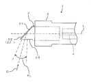
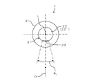
- FIGS. 2 and 3 are diagrams for explaining an incident mode of light to the optical window 2, FIG. 2 is a side view, and FIG. 3 is a front view.
- the tapered surface 21 and the flat surface 23 protrude outward.
- a portion of the optical window 2 accommodated in the optical window accommodating portion 31 of the main body 3 is not formed with the flat surface 23 and remains a cylindrical outer peripheral surface.
- the flat surface 23 of the optical window 2 constitutes a light incident surface.
- light incident on the flat surface 23 from the direction D intersecting the axis L direction is transmitted through the optical window 2 and reflected by the tapered surface 21, and is opposite to the tapered surface 21 in the optical window 2.
- the light is emitted from the end face and guided to the optical fiber 4.
- the tapered surface 21 of the optical window 2 constitutes a reflection surface that reflects light from a direction D different from the axis L direction and enters the optical fiber 4 along the axis L direction.
- the dielectric multilayer film 22 constitutes a reflective film formed on the reflective surface (tapered surface 21).
- the visual field ranges R S and R L depend on the numerical aperture (NA) of the optical fiber 4 and the shape of the optical window 2.
- the flat surface 23 formed on a part of the outer peripheral surface of the optical window 2 is used as an incident surface, and light is incident on the optical window 2 from the flat surface 23 to be formed on one end surface of the optical window 2.
- the light reflected by the tapered surface 21 can be emitted from the other end surface.
- the incident surface it is possible to prevent the incident surface from acting like a lens, and thus the viewing field range RL is not widened. Therefore, the visual field range RL of light incident from the outer peripheral surface of the optical window 2 can be effectively limited.
- the angle range of the visual field range RS viewed from the direction of FIG. 2 is about 23 °
- the visual field range viewed from the direction of FIG. 3 is about 23 °
- the angle range of R L is about 23 °.
- the flat surface 23 can be formed with a simple configuration in which a part of the outer peripheral surface of the optical window 2 is cut in parallel with the axis L direction.
- the dielectric multilayer film 22 is formed on the tapered surface 21, by utilizing the characteristics of the dielectric multilayer film 22, light of a desired wavelength is reflected with high efficiency, The light can enter the optical fiber 4.
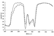
- FIG. 4 is a diagram showing the results of a heat resistance evaluation test of the dielectric multilayer film 22.
- a dielectric multilayer film 22 having a high reflectance at a predetermined wavelength was used, and when heated with a burner for 40 minutes (dot-dash line in FIG. 4), when heated with a constant temperature furnace at 850 ° C. for 3 hours ( The heat resistance was evaluated by comparing each reflectance with the initial reflectance (solid line in FIG. 4).
- the reflectivity of the dielectric multilayer film 22 is unlikely to decrease even when exposed to a high temperature state for a long time. Therefore, even in a high temperature environment where light generated during combustion is measured by the optical measurement probe 1, only the light having a predetermined wavelength is favorably reflected by the dielectric multilayer film 22 and guided to the optical fiber 4. it can.
- the configuration in which the dielectric multilayer film 22 is formed on the tapered surface 21 of the optical window 2 has been described.
- the configuration is not limited to such a configuration, and for example, a configuration in which a metal film 22 ′ is formed on the tapered surface 21 of the optical window 2 may be used.
- the metal film 22 ′ is preferably formed of a metal having a melting point of 1000 ° C. or higher.
- the metal film 22 ′ when the metal film 22 ′ is made of aluminum, it can be made a cheap and highly reflective film.
- the metal film 22 ′ when the metal film 22 ′ is formed of gold, it can be a reflective film that favorably reflects light having a wavelength in the infrared region.
- the metal film 22 ′ is formed of rhodium or lithium, a reflective film having a very high melting point and high heat resistance can be obtained.
- the reflective film is not limited to the dielectric multilayer film 22 and the metal film 22 ′, and can be formed of any material according to necessary characteristics.
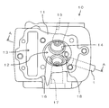
- FIG. 5A is a diagram showing the mounting position of the optical measurement probe 1 in the cylinder head 11.
- FIG. 5B is a cross-sectional view showing the AA cross section in FIG. 5A.
- a combustion chamber 12 surrounded by a cylinder head 11 and a cylinder block and a piston (not shown) is formed.
- the optical measurement probe 1 is attached to the cylinder head 11 so as to face, for example, the combustion chamber 12 as a measurement target.
- the cylinder head 11 is formed with a valve operating system interlocking member accommodation chamber 13 that accommodates a valve operating system interlocking member (for example, a cam chain) (not shown).
- the optical measurement probe 1 is arranged on the opposite side of the cylinder center.
- the cylinder head 11 is formed with an intake port 15 that communicates with an intake valve port 14 that opens toward the combustion chamber 12 and an exhaust port 17 that communicates with an exhaust valve port 16 that opens toward the combustion chamber 12. .
- a probe opening 18 that opens toward the combustion chamber 12 is formed near the intake valve port 14 and the exhaust valve port 16 in the cylinder head 11.
- the probe opening 18 is provided, for example, on the opposite side to the valve train interlocking member accommodation chamber 13 with respect to the intake valve port 14 and the exhaust valve port 16.
- FIG. 6 is a side view showing a modification of the optical measurement probe 1.
- the configuration in which the flat surface 23 constituting the incident surface of the optical window 2 extends in parallel with the axis L direction has been described.
- the flat surface 23 is inclined with respect to the axis L direction.
- the inclination angle of the flat surface 23 with respect to the axis L direction is preferably 1 to 20 °, more preferably 3 to 10 °.
- the other configuration is the same as that of the above-described embodiment. Therefore, the same reference numerals are given to the same configuration, and detailed description is omitted.
- the flat surface 23 is formed so that at least a part thereof overlaps the tapered surface 21 when viewed in a direction orthogonal to the axis L, for example.
- the flat surface 23 is simply configured by cutting a part of the outer peripheral surface of the optical window 2 along the direction inclined with respect to the axis L direction from the end surface of the optical window 2 on the tapered surface 21 side. Can be formed.
- the flat surface 23 By inclining the flat surface 23 with respect to the direction of the axis L of the optical window 2, the flat surface 23 extends along the direction of the axis L of the optical window 2 as in the above embodiment. It is possible to effectively limit the visual field range RS of light incident from the outer peripheral surface. Specifically, the angle range of the visual field range RS viewed from the direction of FIG. 6 (perpendicular to the axis L direction) is about 17 °, and the visual field viewed from the axis L direction orthogonal to FIG. The angle range of the range RL is about 11 °.
- the configuration in which the reflective film is formed on the tapered surface 21 of the optical window 2 constituting the reflective surface has been described.
- the configuration is not limited to the configuration in which the reflective film is formed as long as the light can be reflected by the tapered surface 21 and incident on the optical fiber 4.
- the optical fiber 4 is not limited to the one that guides light to the spectroscope 5, but may be one that guides light to another device.
- the light guide for guiding light to the device is not limited to the optical fiber 4, and the light may be guided to the device using another member.
- the optical measurement probe 1 according to the present invention is not limited to a configuration that is installed in a combustion chamber of an internal combustion engine such as an automobile or a motorcycle, but is installed in any other high-temperature environment to generate light generated during combustion. Can be led to the equipment.
Landscapes
- Physics & Mathematics (AREA)
- General Physics & Mathematics (AREA)
- Chemical & Material Sciences (AREA)
- Spectroscopy & Molecular Physics (AREA)
- Engineering & Computer Science (AREA)
- Immunology (AREA)
- Pathology (AREA)
- Life Sciences & Earth Sciences (AREA)
- Analytical Chemistry (AREA)
- Biochemistry (AREA)
- General Health & Medical Sciences (AREA)
- Health & Medical Sciences (AREA)
- Combustion & Propulsion (AREA)
- Mathematical Physics (AREA)
- Theoretical Computer Science (AREA)
- Investigating Or Analysing Materials By Optical Means (AREA)
- Spectrometry And Color Measurement (AREA)
- Testing Of Engines (AREA)
- Photometry And Measurement Of Optical Pulse Characteristics (AREA)
Abstract
光学測定用プローブ1は、測定対象物から生じる光を機器に導くためのものであって、光学窓2と、光ファイバ4とを備える。光学窓2は、一端面が反射面(テーパ面21)を構成する円柱状に形成されており、外周面の一部に形成された入射面(平坦面23)から入射する光を透過させ、反射面で反射させて他端面から出射させる。光ファイバ4は、光学窓2の他端面から出射する光を機器に導く。
Description
本発明は、測定対象物から生じる光を機器に導くための光学測定用プローブ及びこれを備えた光学測定装置に関するものである。
測定対象物から生じる光を測定するための光学測定装置には、測定対象物からの光を機器に導くために光学プローブが用いられる場合がある。この種の光学プローブは、例えば透明な光学窓と、光ファイバからなる導光体とを備えており、光学窓に入射する光は、導光体を介して機器に導かれる(例えば、下記特許文献1参照)。
この種の光学プローブでは、例えば光学窓が円柱状に形成されており、光学窓の一端面から入射する光が、当該光学窓を透過して他端面から導光体に導かれる。すなわち、光学窓の軸線方向から一直線上に入射する光が、光学窓を介して導光体に導かれるようになっている。
上記のような従来の光学プローブでは、光学窓の軸線に対して所定の視野範囲内から入射する光のみが導光体に導かれる。そのため、光学プローブの設置位置が制限されるような場合には、所望の方向からの光を導光体に導くことができない場合があった。
そこで、本願発明者らは、光学窓の外周面から光を入射させ、入射した光を光学窓の端面で反射させて導光体に導くことができるような光学プローブを想到するに至った。しかしながら、このような光学プローブでは、円弧状に湾曲した光学窓の外周面により光の入射面が構成されているため、その入射面がレンズ(シリンドリカルレンズ)のように作用する。光学窓の外周面の曲率半径が、例えば0.8mm程度と比較的小さいため、曲率が大きくなり、その結果、視野範囲が広くなる。光学プローブの設置位置によっては、視野範囲を制限して、特定の狭い視野範囲内で入射する光のみを測定したい場合もある。
本発明は、上記実情に鑑みてなされたものであり、光学窓の外周面から入射する光の視野範囲を効果的に制限することができる光学測定用プローブ及びこれを備えた光学測定装置を提供することを目的とする。
本発明に係る光学測定用プローブは、測定対象物から生じる光を機器に導くための光学測定用プローブであって、光学窓と、導光体とを備える。前記光学窓は、一端面が反射面を構成する円柱状に形成されており、外周面の一部に形成された入射面から入射する光を透過させ、前記反射面で反射させて他端面から出射させる。前記導光体は、前記光学窓の他端面から出射する光を機器に導く。前記入射面は、平坦面により形成されている。
このような構成によれば、光学窓の外周面の一部に形成された平坦面を入射面として、当該入射面から光学窓に光を入射させ、光学窓の一端面により構成される反射面で反射させた光を他端面から出射させることができる。このように、入射面を平坦面とすることにより、入射面がレンズのように作用することを防止できるため、視野範囲が広くならない。したがって、光学窓の外周面から入射する光の視野範囲を効果的に制限することができる。
前記入射面は、前記光学窓の軸線方向に対して平行に延びていてもよい。
このような構成によれば、光学窓の軸線方向に対して平行に延びる入射面から光学窓に光が入射する。この場合、光学窓の外周面の一部を軸線方向に対して平行に切断するだけの簡単な構成で入射面を形成することができる。
前記入射面は、前記光学窓の軸線方向に対して傾斜していてもよい。
このような構成によれば、光学窓の軸線方向に対して傾斜する入射面から光学窓に光が入射する。この場合、光学窓の外周面の一部を軸線方向に対して傾斜する方向に沿って切断するだけの簡単な構成で入射面を形成することができる。入射面を光学窓の軸線方向に対して傾斜させることにより、入射面が光学窓の軸線方向に沿って延びている場合よりも、光学窓の外周面から入射する光の視野範囲を効果的に制限することができる。
前記光学測定用プローブは、前記反射面に成膜された反射膜をさらに備えていてもよい。
このような構成によれば、反射面に成膜された反射膜の特性を利用することにより、所望の態様で光を反射させ、導光体に入射させることができる。
前記反射膜は、誘電体多層膜であってもよい。
このような構成によれば、反射面に成膜された誘電体多層膜が有する任意の反射率を実現できる特性を利用することにより、所望の波長の光を高効率で反射させ、導光体に入射させることができる。
あるいは、前記反射膜は、金属膜であってもよい。
このような構成によれば、反射面に成膜された金属膜の特性を利用することにより、その金属の種類に応じた態様で光を反射させ、導光体に入射させることができる。
前記光学測定用プローブは、前記光学窓及び前記導光体を保持する本体部をさらに備えていてもよい。この場合、前記光学窓は、前記入射面及び前記反射面が外部に張り出すように前記本体部の端部に取り付けられていてもよい。
このような構成によれば、本体部の端部から外部に張り出した入射面に入射する光を反射面で反射させ、導光体に導くことができるとともに、それ以外の光が導光体に導かれるのを本体部により遮ることができる。したがって、入射面から入射する光のみを良好に導光体に導くことができる。
本発明に係る光学測定用プローブは、前記光学測定用プローブと、前記光学測定用プローブにより導かれた光を検出する検出器とを備える。
また、本発明に係る光学測定用プローブは、前記光学測定用プローブが、測定対象である燃焼室内に臨むように、内燃機関のシリンダヘッドに取り付けられている。
前記シリンダヘッドが、動弁系連動部材を収容する動弁系連動部材収容室を有していてもよい。この場合、前記光学測定用プローブが、前記シリンダヘッドにおける前記動弁系連動部材収容室とは反対側に設けられていてもよい。
本発明によれば、入射面を平坦面とすることにより、入射面がレンズのように作用することを防止できるため、視野範囲が広くならず、その結果、光学窓の外周面から入射する光の視野範囲を効果的に制限することができる。
図1は、本発明の一実施形態に係る光学測定用プローブ1を備えた光学測定装置の構成例を示す図である。図1では、光学測定用プローブ1の具体的構成を部分断面図で示している。
本実施形態に係る光学測定用プローブ1は、燃焼時などに測定対象物から生じる光を機器に導くためのものであり、例えば自動車や自動二輪車などの内燃機関の燃焼室に設置され、当該燃焼室内における燃焼状態を評価する際などに使用される。この光学測定用プローブ1には、光学窓2、本体部3及び光ファイバ4などが備えられている。図1では、光学測定用プローブ1における本体部3の先端部分のみを断面図で示している。
光学窓2は、例えば石英又はサファイアなどにより形成され、外部から入射する光を透過させて本体部3内に取り込むことができる。本体部3は、例えばステンレス鋼などの金属により形成されている。この本体部3により、光学窓2及び光ファイバ4が一体的に保持され、光学窓2を透過した光が、軸線L方向に沿って光ファイバ4の一端部に入射するようになっている。
本体部3は、例えば円筒状に形成され、その一端部に光学窓2が収容されている。具体的には、本体部3の一端部に、光学窓2の外径に対応する内径を有する凹部が形成されており、当該凹部が光学窓2を収容するための光学窓収容部31を構成している。また、本体部3には、他端部側から延びる凹部により、光ファイバ4を収容するための光ファイバ収容部32が形成されている。光学窓収容部31と光ファイバ収容部32とは、連通孔33を介して連通しており、光学窓2を透過した光は、連通孔33を介して光ファイバ収容部32内の光ファイバ4に入射するようになっている。
本実施形態に係る光学測定装置には、上述のような光学測定用プローブ1に加えて、分光器5及び検出器6などが備えられている。分光器5は、光ファイバ4の他端部側に配置されている。光ファイバ4の他端部側にはコネクタ41が取り付けられており、当該コネクタ41が分光器5に接続されている。光学測定用プローブ1により受光された光は、光ファイバ4の他端部側から分光器5に入射し、当該分光器5により分光された光が、検出器6で検出されるようになっている。
この例では、光学窓2は円柱状に形成され、その入射側の端部にテーパ面21が形成されている。具体的には、光学窓2は、光ファイバ4と同じ軸線Lに沿って延びており、その軸線L方向における光ファイバ4側とは反対側の端面がテーパ面21により形成されている。テーパ面21は、軸線Lに対して30°~60°の角度で傾斜していることが好ましく、この例では約45°の角度で傾斜している。
テーパ面21には、例えば誘電体多層膜22が成膜されている。誘電体多層膜22は、屈折率の異なる複数種類の膜により構成されており、これらの膜をテーパ面21に対して順次蒸着させることにより、適切な厚みの膜が積層された誘電体多層膜22を光学窓2と一体的に構成することができる。
誘電体多層膜22は、屈折率の低い材料により形成された低屈折率膜と、屈折率の高い材料により形成された高屈折率膜とが、交互に積層された構成であってもよい。この場合、例えば低屈折率膜をSiO2膜により構成し、高屈折率膜をTa2O5膜により構成することができる。このような誘電体多層膜22は、イオンプレーティング法などの公知の方法を用いて形成することができる。
この種の誘電体多層膜22は、所定の波長の光を高効率で反射させる特性を有している。ただし、誘電体多層膜22は、上記のような構成に限られるものではなく、HfO2、Al2O3、MgF2、TiO2、ZrO2などの他の各種材料を用いて構成することができる。また、3種類以上の光学薄膜を積層することにより誘電体多層膜22が構成されていてもよい。
この場合、光学測定用プローブ1の使用環境下で誘電体多層膜22に付着する物質(例えばススや油など)に応じて、その物質が反射率に与える影響を加味して誘電体多層膜22を設計し形成されることが好ましい。
光学窓2におけるテーパ面21側の外周面には、軸線L方向に対して平行に延びる平坦面23が形成されている。平坦面23は、例えば軸線Lに対して直交方向に見たときに、その少なくとも一部がテーパ面21と重なるように形成されている。この例では、平坦面23が、光学窓2におけるテーパ面21側の端面から軸線Lに対して平行方向に延びるように形成された段差部により構成されているが、これに限らず、例えば光学窓2の外周面に形成された凹部により構成されていてもよい。
図2及び図3は、光学窓2への光の入射態様について説明するための図であり、図2は側面図、図3は正面図をそれぞれ示している。
光学窓2が本体部3の端部に取り付けられた状態では、テーパ面21及び平坦面23が外部に張り出している。光学窓2における本体部3の光学窓収容部31内に収容されている部分は、平坦面23が形成されておらず、円筒状の外周面のままである。これにより、光学窓21を本体部3に対して封止する際の安定性及び耐久性を確保することができる。
本実施形態では、光学窓2の平坦面23が光の入射面を構成している。これにより、軸線L方向に対して交差する方向Dから平坦面23に入射する光は、光学窓2内を透過してテーパ面21で反射し、光学窓2におけるテーパ面21とは反対側の端面から出射して光ファイバ4に導かれる。
すなわち、光学窓2のテーパ面21は、軸線L方向とは異なる方向Dからの光を反射させ、軸線L方向に沿って光ファイバ4に入射させる反射面を構成している。また、誘電体多層膜22は、上記反射面(テーパ面21)に成膜された反射膜を構成している。
光ファイバ4には、光学窓2の平坦面23から入射する光のうち、方向Dを中心とする所定の視野範囲RS,RL内の光のみが入射し、それ以外の光が光ファイバ4に入射するのを本体部3により遮ることができる。したがって、所定の方向Dからの光のみを良好に光ファイバ4に入射させることができる。視野範囲RS,RLは、光ファイバ4の開口数(NA)と光学窓2の形状に依存している。
本実施形態では、光学窓2の外周面の一部に形成された平坦面23を入射面として、当該平坦面23から光学窓2に光を入射させ、光学窓2の一端面に形成されたテーパ面21で反射させた光を他端面から出射させることができる。このように、入射面を平坦面23とすることにより、入射面がレンズのように作用することを防止できるため、視野範囲RLが広くならない。したがって、光学窓2の外周面から入射する光の視野範囲RLを効果的に制限することができる。
具体的には、図2の方向(軸線L方向に対して直交方向)から見た視野範囲RSの角度範囲は約23°であり、図3の方向(軸線L方向)から見た視野範囲RLの角度範囲は約23°である。入射面を平坦面23とすることにより、特に図3の方向から見た視野範囲RLを効果的に制限することができ、円弧状に湾曲した光学窓の外周面のままでは角度範囲が約60°であった視野範囲RS,RLが、上記の通り約23°の角度範囲まで制限される。
また、本実施形態では、光学窓2の軸線L方向に対して平行に延びる平坦面23から光学窓2に光が入射する。この場合、光学窓2の外周面の一部を軸線L方向に対して平行に切断するだけの簡単な構成で平坦面23を形成することができる。
特に、本実施形態では、テーパ面21に誘電体多層膜22が成膜されているため、当該誘電体多層膜22の特性を利用することにより、所望の波長の光を高効率で反射させ、光ファイバ4に入射させることができる。
図4は、誘電体多層膜22の耐熱性評価試験の結果を示す図である。この試験では、所定の波長において高い反射率を有する誘電体多層膜22を使用し、バーナーで40分加熱した場合(図4における一点鎖線)と、850℃の恒温炉で3時間加熱した場合(図4における破線)とについて、それぞれの反射率を初期(図4における実線)の反射率と比較することにより耐熱性の評価を行った。
この図4の結果から、長時間にわたって高温状態に晒された場合でも誘電体多層膜22の反射率は低下しにくいことが分かる。したがって、燃焼時に生じる光を光学測定用プローブ1で測定するような高温環境下であっても、誘電体多層膜22により所定の波長の光のみを良好に反射させ、光ファイバ4に導くことができる。
上記実施形態では、誘電体多層膜22が光学窓2のテーパ面21に成膜された構成について説明した。しかし、このような構成に限らず、例えば金属膜22´が光学窓2のテーパ面21に成膜された構成であってもよい。この場合、テーパ面21に成膜された金属膜22´の特性を利用することにより、その金属の種類に応じた態様で光を反射させ、光ファイバ4に入射させることができる。上記金属膜22´は、融点が1000℃以上の金属により形成されていることが好ましい。
例えば、上記金属膜22´をアルミニウムにより形成した場合には、安価で高い反射率を有する反射膜とすることができる。上記金属膜22´を金により形成した場合には、赤外域の波長の光を良好に反射させる反射膜とすることができる。上記金属膜22´をロジウムやリテニウムにより形成した場合には、融点が非常に高く耐熱性が高い反射膜とすることができる。
このように、テーパ面21に成膜された反射膜の特性を利用することにより、所望の態様で光を反射させ、光ファイバ4に入射させることができる。上記反射膜は、誘電体多層膜22や金属膜22´に限らず、必要な特性に応じた任意の材料で形成することができる。
図5Aは、シリンダヘッド11における光学測定用プローブ1の取付位置を示す図である。また、図5Bは、図5AにおけるA-A断面を示す断面図である。例えば自動車や自動二輪車などの内燃機関10には、シリンダヘッド11と図示されないシリンダブロック及びピストンにより囲まれた燃焼室12が形成されている。
光学測定用プローブ1は、例えば測定対象である燃焼室12内に臨むように、シリンダヘッド11に取り付けられる。具体的には、シリンダヘッド11には、図示されない動弁系連動部材(例えばカムチェーンなど)を収容する動弁系連動部材収容室13が形成されており、当該動弁系連動部材収容室13に対してシリンダ中心を挟んで反対側に光学測定用プローブ1が配置される。
シリンダヘッド11には、燃焼室12に向けて開口する吸気弁口14に連通した吸気ポート15と、燃焼室12に向けて開口する排気弁口16に連通した排気ポート17とが形成されている。この例では、シリンダヘッド11における吸気弁口14及び排気弁口16の近傍に、燃焼室12に向けて開口するプローブ用開口部18が形成されている。
プローブ用開口部18は、例えば吸気弁口14及び排気弁口16に対して、動弁系連動部材収容室13とは反対側に設けられている。内燃機関10の燃焼室12内における燃焼状態を評価する際などには、プローブ用開口部18を介して、燃焼室12内に生じる光を光学測定用プローブ1に導くことができる。
図6は、光学測定用プローブ1の変形例を示す側面図である。上記実施形態では、光学窓2の入射面を構成する平坦面23が、軸線L方向に対して平行に延びるような構成について説明した。これに対して、図6の例では、平坦面23が軸線L方向に対して傾斜している。軸線L方向に対する平坦面23の傾斜角度は、1~20°であることが好ましく、3~10°であればより好ましい。この点を除けば、他の構成は上記実施形態と同様であるため、同様の構成については図に同一符号を付して詳細な説明を省略する。
この例においても、平坦面23は、例えば軸線Lに対して直交方向に見たときに、その少なくとも一部がテーパ面21と重なるように形成されている。この例では、光学窓2におけるテーパ面21側の端面から、光学窓2の外周面の一部を軸線L方向に対して傾斜する方向に沿って切断するだけの簡単な構成で平坦面23を形成することができる。
平坦面23を光学窓2の軸線L方向に対して傾斜させることにより、上記実施形態のように平坦面23が光学窓2の軸線L方向に沿って延びている場合よりも、光学窓2の外周面から入射する光の視野範囲RSを効果的に制限することができる。具体的には、図6の方向(軸線L方向に対して直交方向)から見た視野範囲RSの角度範囲は約17°であり、図6に対して直交する軸線L方向から見た視野範囲RLの角度範囲は約11°である。
以上の実施形態では、反射面を構成する光学窓2のテーパ面21に、反射膜が形成された構成について説明した。しかし、テーパ面21で光を反射させて光ファイバ4に入射させることができれば、反射膜が成膜された構成に限られるものではない。
光ファイバ4は、分光器5に光を導くものに限らず、他の機器に光を導くものであってもよい。また、光を機器に導くための導光体は、光ファイバ4に限らず、他の部材を用いて光を機器に導いてもよい。
なお、本発明に係る光学測定用プローブ1は、自動車や自動二輪車などの内燃機関の燃焼室に設置されるような構成に限らず、他のあらゆる高温環境下に設置して、燃焼時に生じる光を機器に導くことができる。
1 光学測定用プローブ
2 光学窓
3 本体部
4 光ファイバ
5 分光器
6 検出器
10 内燃機関
11 シリンダヘッド
12 燃焼室
13 動弁系連動部材収容室
14 吸気弁口
15 吸気ポート
16 排気弁口
17 排気ポート
18 プローブ用開口部
21 テーパ面
22 誘電体多層膜
22´ 金属膜
23 平坦面
31 光学窓収容部
32 光ファイバ収容部
33 連通孔
41 コネクタ
2 光学窓
3 本体部
4 光ファイバ
5 分光器
6 検出器
10 内燃機関
11 シリンダヘッド
12 燃焼室
13 動弁系連動部材収容室
14 吸気弁口
15 吸気ポート
16 排気弁口
17 排気ポート
18 プローブ用開口部
21 テーパ面
22 誘電体多層膜
22´ 金属膜
23 平坦面
31 光学窓収容部
32 光ファイバ収容部
33 連通孔
41 コネクタ
Claims (10)
- 測定対象物から生じる光を機器に導くための光学測定用プローブであって、
一端面が反射面を構成する円柱状に形成されており、外周面の一部に形成された入射面から入射する光を透過させ、前記反射面で反射させて他端面から出射させる光学窓と、
前記光学窓の他端面から出射する光を機器に導く導光体とを備え、
前記入射面は、平坦面により形成されていることを特徴とする光学測定用プローブ。 - 前記入射面は、前記光学窓の軸線方向に対して平行に延びていることを特徴とする請求項1に記載の光学測定用プローブ。
- 前記入射面は、前記光学窓の軸線方向に対して傾斜していることを特徴とする請求項1に記載の光学測定用プローブ。
- 前記反射面に成膜された反射膜をさらに備えることを特徴とする請求項1乃至3のいずれか一項に記載の光学測定用プローブ。
- 前記反射膜が、誘電体多層膜であることを特徴とする請求項4に記載の光学測定用プローブ。
- 前記反射膜が、金属膜であることを特徴とする請求項4に記載の光学測定用プローブ。
- 前記光学窓及び前記導光体を保持する本体部をさらに備え、
前記光学窓は、前記入射面及び前記反射面が外部に張り出すように前記本体部の端部に取り付けられていることを特徴とする請求項1乃至6のいずれか一項に記載の光学測定用プローブ。 - 請求項1乃至7のいずれか一項に記載の光学測定用プローブと、
前記光学測定用プローブにより導かれた光を検出する検出器とを備えることを特徴とする光学測定装置。 - 請求項1乃至7のいずれか一項に記載の光学測定用プローブが、
測定対象である燃焼室内に臨むように、内燃機関のシリンダヘッドに取り付けられたことを特徴とする光学測定装置。 - 前記シリンダヘッドが、動弁系連動部材を収容する動弁系連動部材収容室を有し、
前記光学測定用プローブが、前記シリンダヘッドにおける前記動弁系連動部材収容室とは反対側に設けられることを特徴とする請求項9に記載の光学測定装置。
Priority Applications (4)
| Application Number | Priority Date | Filing Date | Title |
|---|---|---|---|
| DE112016006667.8T DE112016006667T5 (de) | 2016-03-31 | 2016-03-31 | Optische messsonde und damit versehene optische messvor-richtung |
| US16/085,127 US20190094132A1 (en) | 2016-03-31 | 2016-03-31 | Optical measurement probe and optical measurement device provided with same |
| PCT/JP2016/060753 WO2017168703A1 (ja) | 2016-03-31 | 2016-03-31 | 光学測定用プローブ及びこれを備えた光学測定装置 |
| JP2018508297A JPWO2017168703A1 (ja) | 2016-03-31 | 2016-03-31 | 光学測定用プローブ及びこれを備えた光学測定装置 |
Applications Claiming Priority (1)
| Application Number | Priority Date | Filing Date | Title |
|---|---|---|---|
| PCT/JP2016/060753 WO2017168703A1 (ja) | 2016-03-31 | 2016-03-31 | 光学測定用プローブ及びこれを備えた光学測定装置 |
Publications (1)
| Publication Number | Publication Date |
|---|---|
| WO2017168703A1 true WO2017168703A1 (ja) | 2017-10-05 |
Family
ID=59962811
Family Applications (1)
| Application Number | Title | Priority Date | Filing Date |
|---|---|---|---|
| PCT/JP2016/060753 Ceased WO2017168703A1 (ja) | 2016-03-31 | 2016-03-31 | 光学測定用プローブ及びこれを備えた光学測定装置 |
Country Status (4)
| Country | Link |
|---|---|
| US (1) | US20190094132A1 (ja) |
| JP (1) | JPWO2017168703A1 (ja) |
| DE (1) | DE112016006667T5 (ja) |
| WO (1) | WO2017168703A1 (ja) |
Citations (6)
| Publication number | Priority date | Publication date | Assignee | Title |
|---|---|---|---|---|
| JP2001147157A (ja) * | 1999-09-28 | 2001-05-29 | Avl List Gmbh | 光電子測定装置 |
| JP2003515736A (ja) * | 1999-12-02 | 2003-05-07 | エフカーエフエス フォルシュングスインスティトゥート フュア クラフトファールヴェーゼン ウント ファールツォイクモトーレン | 内燃機関の燃焼室内で実行される燃焼過程を監視するための装置 |
| WO2005024489A1 (ja) * | 2003-09-05 | 2005-03-17 | Nabtesco Corporation | 光部品用ガイド機構 |
| JP4597251B1 (ja) * | 2009-05-22 | 2010-12-15 | ファイバーラボ株式会社 | 光ファイバセンサ装置、光ファイバを用いたセンシング方法 |
| WO2011040589A1 (ja) * | 2009-09-30 | 2011-04-07 | イマジニアリング株式会社 | 観察用プラグ、及び点火観察システム |
| JP3182445U (ja) * | 2012-12-28 | 2013-03-28 | 株式会社島津製作所 | 光学測定用プローブ及びこれを備えた光学測定装置 |
Family Cites Families (7)
| Publication number | Priority date | Publication date | Assignee | Title |
|---|---|---|---|---|
| US5219227A (en) * | 1990-08-13 | 1993-06-15 | Barrack Technology Limited | Method and apparatus for determining burned gas temperature, trapped mass and NOx emissions in an internal combustion engine |
| GB0010123D0 (en) * | 2000-04-27 | 2000-06-14 | Univ Nottingham | Planar light sheet anemometers |
| JP5264242B2 (ja) * | 2008-03-26 | 2013-08-14 | キヤノン株式会社 | 原子磁力計及び磁力計測方法 |
| WO2011132661A1 (ja) * | 2010-04-23 | 2011-10-27 | コニカミノルタオプト株式会社 | プローブ |
| US9195044B2 (en) * | 2013-08-15 | 2015-11-24 | Siemens Energy, Inc | Optical probe having an inner tube with separable tube sections to house optical elements |
| JP6088939B2 (ja) * | 2013-08-26 | 2017-03-01 | 株式会社島津製作所 | プラグ内蔵型光学測定用プローブ及びこれを備えた光学測定装置 |
| DE112014006391T5 (de) * | 2014-02-21 | 2016-11-17 | Honda Motor Co., Ltd. | Optische Messsonde und mit selbiger versehene optische Messvorrichtung |
-
2016
- 2016-03-31 JP JP2018508297A patent/JPWO2017168703A1/ja active Pending
- 2016-03-31 DE DE112016006667.8T patent/DE112016006667T5/de not_active Ceased
- 2016-03-31 WO PCT/JP2016/060753 patent/WO2017168703A1/ja not_active Ceased
- 2016-03-31 US US16/085,127 patent/US20190094132A1/en not_active Abandoned
Patent Citations (6)
| Publication number | Priority date | Publication date | Assignee | Title |
|---|---|---|---|---|
| JP2001147157A (ja) * | 1999-09-28 | 2001-05-29 | Avl List Gmbh | 光電子測定装置 |
| JP2003515736A (ja) * | 1999-12-02 | 2003-05-07 | エフカーエフエス フォルシュングスインスティトゥート フュア クラフトファールヴェーゼン ウント ファールツォイクモトーレン | 内燃機関の燃焼室内で実行される燃焼過程を監視するための装置 |
| WO2005024489A1 (ja) * | 2003-09-05 | 2005-03-17 | Nabtesco Corporation | 光部品用ガイド機構 |
| JP4597251B1 (ja) * | 2009-05-22 | 2010-12-15 | ファイバーラボ株式会社 | 光ファイバセンサ装置、光ファイバを用いたセンシング方法 |
| WO2011040589A1 (ja) * | 2009-09-30 | 2011-04-07 | イマジニアリング株式会社 | 観察用プラグ、及び点火観察システム |
| JP3182445U (ja) * | 2012-12-28 | 2013-03-28 | 株式会社島津製作所 | 光学測定用プローブ及びこれを備えた光学測定装置 |
Also Published As
| Publication number | Publication date |
|---|---|
| US20190094132A1 (en) | 2019-03-28 |
| DE112016006667T5 (de) | 2018-12-20 |
| JPWO2017168703A1 (ja) | 2018-10-11 |
Similar Documents
| Publication | Publication Date | Title |
|---|---|---|
| CN106471332B (zh) | 多波长共焦测量装置 | |
| EP2120071A1 (en) | Light-dividing element and distance measuring device | |
| JP2017504828A5 (ja) | ||
| JP6263411B2 (ja) | 光学式センサチップ | |
| EP3067686B1 (en) | Transmission probe, system and immersion transmission measurement method | |
| FI95322B (fi) | Spektroskooppinen mittausanturi väliaineiden analysointiin | |
| CN110383043A (zh) | 光学气体传感器 | |
| RU2010139148A (ru) | Сенсорная головка, калибровочная система и измерительная система для реагента в виде сухого порошка | |
| JP6320510B2 (ja) | 光学測定用プローブ及びこれを備えた光学測定装置 | |
| WO2017168703A1 (ja) | 光学測定用プローブ及びこれを備えた光学測定装置 | |
| US9759178B2 (en) | Plug built-in type optical measurement probe, and optical measurement device provided with the same | |
| US9239298B2 (en) | Optical measurement probe, and optical measurement device provided with the same | |
| WO2010084523A1 (ja) | 湿度センサ及び湿度測定装置 | |
| CN102947689B (zh) | 发光单元 | |
| JP2019007885A (ja) | 反射鏡、多重反射セル、ガス濃度モニタ及び反射鏡の製造方法 | |
| JP2008232947A (ja) | 光ファイバ型表面プラズモンセンサ及びそれを用いた測定装置 | |
| JP6588083B2 (ja) | 照準システムおよび方法 | |
| KR102223821B1 (ko) | 다종 가스 측정 장치 | |
| JP6488956B2 (ja) | 光検出装置 | |
| JP6317277B2 (ja) | 内燃機関の燃料ガス濃度測定装置 | |
| US20240310193A1 (en) | Off-axis fiber optic sensor | |
| JP2014228364A (ja) | ボア変形量測定装置 | |
| JP5483163B2 (ja) | レーザガス分析装置 | |
| US20030099427A1 (en) | Optical conductor | |
| JP2019109075A (ja) | ガス温度計測装置 |
Legal Events
| Date | Code | Title | Description |
|---|---|---|---|
| ENP | Entry into the national phase |
Ref document number: 2018508297 Country of ref document: JP Kind code of ref document: A |
|
| 121 | Ep: the epo has been informed by wipo that ep was designated in this application |
Ref document number: 16896920 Country of ref document: EP Kind code of ref document: A1 |
|
| 122 | Ep: pct application non-entry in european phase |
Ref document number: 16896920 Country of ref document: EP Kind code of ref document: A1 |