WO2017168682A1 - ピーク検出方法及びデータ処理装置 - Google Patents
ピーク検出方法及びデータ処理装置 Download PDFInfo
- Publication number
- WO2017168682A1 WO2017168682A1 PCT/JP2016/060677 JP2016060677W WO2017168682A1 WO 2017168682 A1 WO2017168682 A1 WO 2017168682A1 JP 2016060677 W JP2016060677 W JP 2016060677W WO 2017168682 A1 WO2017168682 A1 WO 2017168682A1
- Authority
- WO
- WIPO (PCT)
- Prior art keywords
- peak
- detection
- detection sensitivity
- detected
- peaks
- Prior art date
- Legal status (The legal status is an assumption and is not a legal conclusion. Google has not performed a legal analysis and makes no representation as to the accuracy of the status listed.)
- Ceased
Links
Images


Classifications
-
- G—PHYSICS
- G01—MEASURING; TESTING
- G01N—INVESTIGATING OR ANALYSING MATERIALS BY DETERMINING THEIR CHEMICAL OR PHYSICAL PROPERTIES
- G01N30/00—Investigating or analysing materials by separation into components using adsorption, absorption or similar phenomena or using ion-exchange, e.g. chromatography or field flow fractionation
- G01N30/02—Column chromatography
- G01N30/86—Signal analysis
- G01N30/8624—Detection of slopes or peaks; baseline correction
- G01N30/8631—Peaks
-
- G—PHYSICS
- G01—MEASURING; TESTING
- G01N—INVESTIGATING OR ANALYSING MATERIALS BY DETERMINING THEIR CHEMICAL OR PHYSICAL PROPERTIES
- G01N30/00—Investigating or analysing materials by separation into components using adsorption, absorption or similar phenomena or using ion-exchange, e.g. chromatography or field flow fractionation
- G01N30/02—Column chromatography
- G01N30/86—Signal analysis
Definitions
- the present invention relates to a method for detecting a peak from a chromatogram obtained by, for example, a chromatograph, a spectrum obtained by a mass spectrometer, a spectroscopic device, or the like, and a data processing apparatus for executing the method.
- a chromatograph is one of the devices that analyze the components contained in a sample.
- a sample is placed on a mobile phase flow and introduced into a column.
- Each component in the sample is temporally separated in the column and then detected by a detector to create a chromatogram.
- each component is identified from the peak position on a chromatogram, and the density
- FIGS. 5 (a) and 5 (b) show examples of such chromatograms.
- the broken line in the figure shows the profile of the chromatogram when two peaks exist alone, and the solid line shows the profile of the chromatogram in which these two peaks overlap.
- the profiles of the two peaks are the same, but the difference in retention time is smaller in (b) than in (a).
- each peak top appears while two peaks overlap.
- JP 07-098270 A Japanese Unexamined Patent Publication No. 2015-049136
- an operation of automatically detecting a peak having a S / N (signal / noise) ratio equal to or higher than a predetermined threshold from the chromatogram is performed (for example, see Patent Document 2).
- the shoulder peak can be detected by lowering the S / N ratio.
- the threshold is too low, there is a possibility that noise is erroneously detected as a peak.
- true peaks and noise can often be visually discriminated, if there are many erroneously detected peaks, it takes time to distinguish them from true peaks.
- the threshold of the S / N ratio is increased, there is a possibility that the shoulder peak cannot be detected.
- the problem to be solved by the present invention is to provide a peak detection method and a data processing apparatus suitable for detecting a shoulder peak.
- the peak detection method according to the present invention made to solve the above problems is as follows.
- a peak is detected with a second detection sensitivity different from the first detection sensitivity in the first peak detection step.
- the second detection sensitivity is higher than the first detection sensitivity, the peak not detected in the first peak detection step can be detected in the second peak detection step, thereby detecting the shoulder peak. It becomes easy.
- the second detection sensitivity is set lower than the first detection sensitivity, in the second peak detection step, a part of the detected peak is not detected in the first peak detection step, thereby reducing noise or the like. Those detected as misidentified as shoulder peaks can be excluded.
- the shoulder peak candidate extraction step is detected with a relatively low first detection sensitivity from one or more peaks detected in the second peak detection step using a higher second detection sensitivity. Peaks that can be easily identified are excluded, and peaks that are not detected in the first peak detection step are extracted. Thereby, the shoulder peak candidate which is a peak which may be a shoulder peak is obtained.
- the thus obtained shoulder peak candidates may include noise and the like in addition to the true shoulder peak. However, since the candidates are narrowed down, it becomes easy to select the true shoulder peak and noise.
- a peak not detected in the second peak detection step is selected from one or a plurality of peaks detected in the first peak detection step. It can also take the structure of having the shoulder peak exclusion candidate extraction step to extract. According to this configuration, the shoulder peak exclusion candidate extraction step is detected with a relatively low second detection sensitivity from one or more peaks detected in the first peak detection step using a higher first detection sensitivity. Peaks that are easy to identify are excluded, and peaks that are not detected in the second peak detection step are extracted. Thereby, a shoulder peak exclusion candidate that may be noise or the like instead of the shoulder peak is obtained. Although a shoulder peak exclusion candidate may include a true shoulder peak, since the candidates are narrowed down, it becomes easy to select a true shoulder peak and noise.
- the peak detection method it is desirable that one or both of the first detection sensitivity and the second detection sensitivity can be set by the user. Thereby, the user can appropriately change the first detection sensitivity and the second detection sensitivity while looking at the extraction result of the shoulder peak candidates, and thereby the true shoulder peak can be extracted more easily.
- the data processing apparatus A first peak detector for detecting one or more peaks from the data to be detected with a first detection sensitivity; A second peak detector for detecting one or more peaks from the data with a second detection sensitivity different from the first detection sensitivity; It is characterized by having.
- Each of these units is embodied by a central processing unit (CPU) of a computer, a memory, software, and the like.
- shoulder peak (or not shoulder peak) candidates can be extracted from peaks that are detected on the one hand and not detected on the other hand, and thereby shoulder peaks can be extracted. Can be detected appropriately and easily.
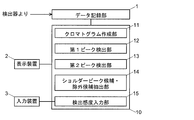
- FIG. 1 is a schematic configuration diagram showing an embodiment of a data processing apparatus according to the present invention.
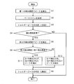
- the flowchart which shows one Embodiment of the peak detection method which concerns on this invention.
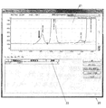
- the figure of the screen of the display apparatus which shows the example which detected the peak with the 1st detection sensitivity.
- the figure of the screen of the display apparatus which shows the example which detected the peak with 2nd detection sensitivity.
- the shoulder peak candidates are extracted from the chromatogram by the procedure shown in the flowchart shown in FIG. 2 using the data processing apparatus 10 shown in FIG.
- the data processing device 10 of this embodiment is used together with the data recording unit 1, the input device 3, and the display device 2.
- the data recording unit 1 is a device that records data obtained at the time of measurement by a detector included in a liquid chromatograph, a gas chromatograph, or the like, and includes a hard disk, a memory, and the like.
- the data recording unit 1 is provided outside the data processing apparatus 10 in the example shown in FIG. 1, but may be provided inside the data processing apparatus 10.
- the display device 2 is a display that displays information during data processing by the data processing device 10 and a result of the data processing.
- the input device 3 is a device for a user to input necessary information to be described later to the data processing device 10, and includes a keyboard, a mouse, and the like.
- the data processing apparatus 10 includes a chromatogram creation unit 11, a first peak detection unit 12, a second peak detection unit 13, a shoulder peak candidate / exclusion candidate extraction unit 14, and a detection sensitivity input unit 15.
- Each of these units is actually embodied by hardware and software such as a CPU and memory of a computer.
- functions of each unit of the data processing device 10 and the peak detection method of this embodiment will be described with reference to the flowchart of FIG. 2 and the window 20 displayed on the display device shown in FIGS. 3 and 4.
- the case of extracting shoulder peak candidates from a chromatogram will be described as an example, but the same applies to the case of extracting shoulder peak candidates from a spectrum, except for special points.
- the chromatogram creation unit 11 acquires data from the data recording unit 1 and creates a chromatogram by a method similar to the conventional method.
- the chromatogram creation unit 11 acquires data from the data recording unit 1 and creates a chromatogram by a method similar to the conventional method.
- the first peak detector 12 detects a peak with a first detection sensitivity from the generated chromatogram.
- the first detection sensitivity is set as a numerical value of the S / N ratio.
- the numerical value of the first detection sensitivity may be input to the detection sensitivity input unit 15 by the user using the input device 3, or may be a fixed value.
- Peak detection is performed using a method similar to the conventional method. For example, assuming that a temporary peak exists at a point where the chromatogram has a maximum value or an inflection point, the S / N ratio of the temporary peak is equal to or higher than the first detection sensitivity (which is a numerical value of the S / N ratio). If there is, the temporary peak is detected as an actual peak.
- the temporary peak is not detected as an actual peak.
- the peak detection in step S1 may be performed on the entire generated chromatogram, or only within the range after the user specifies the range of the retention time using the input device 3. Also good.
- the detected peak is indicated by adding a mark or a numerical value to the peak top position on the chromatogram displayed on the chromatogram display unit 21 in the window 20.
- the thick downward arrow in FIG. 3 is attached for the following description, and does not indicate the detected peak.
- the baseline of the chromatogram is determined based on the peak detected in step S1 (step S2).
- the determination of the baseline is not an essential operation in the data processing method according to the present invention, but is an operation usually performed in chromatogram data processing.
- the baseline is determined using a method similar to the conventional method. For example, as the retention time elapses, the absolute value of the slope of the chromatogram increases beyond the specified value after the peak start point, and the absolute value of the slope (negative slope value) increases past the peak top. A point where the peak value is reduced to a predetermined value or less is set as the peak end point, and a straight line connecting the start point and the end point is determined as a baseline between the two points.
- step S3 it is determined whether they are shoulder peaks or other than shoulder peaks such as noise (step S3). ). In this embodiment, this determination is made visually by the user.
- the detection sensitivity input unit 15 allows the user to input from the input device 3 whether or not to change the peak detection sensitivity (step S4). Specifically, for example, “Do you want to change the detection sensitivity? Yes ⁇ ⁇ No” or the like is displayed on the screen of the display device 2, and the user selects “Yes” or “No” using the input device 3. To do. Alternatively, an input field for inputting a numerical value of the detection sensitivity is displayed on the screen of the display device 2, and the detection sensitivity is changed when the user inputs a numerical value in the input field using the input device 3. Also good. In this case, the detection sensitivity can be increased or decreased depending on the input numerical value. Note that, in step S4, two options of whether to increase the detection sensitivity (do not change the detection sensitivity) or two options of whether to decrease the detection sensitivity may be indicated.
- a processing command input unit 22 is provided below the chromatogram display unit 21, and the user inputs a numerical value of detection sensitivity to the processing command input unit 22 as follows.
- the processing command input unit 22 has three columns of “time”, “processing command”, and “numerical value”, and in the initial state, one set of input columns for inputting these three data is displayed ( (See FIG. 3).
- the time column enter the retention time that will be the starting point of the data processing range.
- one processing command can be selected from a plurality of types of processing commands using a pull-down menu.
- “NRLevel (Shoulder) ” which is a command for changing the detection sensitivity is selected.
- step S4 If the user selects No in step S4, the determination result in step S3 is set as a final version, and the process is terminated. On the other hand, if the user selects Yes in step S4, the peak is detected from the chromatogram with the second detection sensitivity (step S5).
- the second detection sensitivity corresponds to a numerical value input by the user in the numerical value column, but the input method of the second detection sensitivity is not limited to this example. Instead of the user inputting the second detection sensitivity, a fixed value may be used.
- Step S6 may be automatically performed by the shoulder peak candidate / exclusion candidate extraction unit 14 or may be performed by the user.
- the shoulder peak candidate / exclusion candidate extraction unit 14 is not detected with the first detection sensitivity in step S1 and the second detection sensitivity in step S5.
- the peaks detected in (1) are extracted (step S7-1).
- This step may be automatically performed by the shoulder peak candidate / exclusion candidate extraction unit 14, or the shoulder peak candidate / exclusion candidate extraction unit 14 displays the two detection results in steps S1 and S5 on the window 20.
- the user may extract a shoulder peak candidate from the peak detected with the second detection sensitivity.
- the latter means that the user can finally extract shoulder peak candidates by comparing the two detection results, and the fact that the following determination operations can be performed simultaneously: There is.
- the shoulder peak candidate / exclusion candidate extraction unit 14 detects the first detection sensitivity in step S1 and the second detection in step S5. Peaks that are not detected by sensitivity are extracted (step S7-2). This step may also be performed automatically, or may be performed by the user based on the detection result displayed on the window 20.
- step S7-1 or step S7-2 whether the peak extracted by the shoulder peak candidate / exclusion candidate extraction unit 14 is a shoulder peak or something other than a shoulder peak such as noise in step S8 Determine. This determination is made visually by the user in this embodiment, as in step S3. With the above operation, the peak detection method of this embodiment is completed.
- the present invention is not limited to the above embodiment, and can be appropriately modified within the scope of the gist of the present invention.
Landscapes
- Physics & Mathematics (AREA)
- Health & Medical Sciences (AREA)
- Life Sciences & Earth Sciences (AREA)
- Chemical & Material Sciences (AREA)
- Analytical Chemistry (AREA)
- Biochemistry (AREA)
- General Health & Medical Sciences (AREA)
- General Physics & Mathematics (AREA)
- Immunology (AREA)
- Pathology (AREA)
- Other Investigation Or Analysis Of Materials By Electrical Means (AREA)
- Investigating, Analyzing Materials By Fluorescence Or Luminescence (AREA)
Abstract
本発明に係るピーク検出方法は、ピーク検出対象のデータから第1検出感度で1又は複数のピークを検出する第1ピーク検出ステップ(S1)と、前記データから、前記第1検出感度とは異なる第2検出感度で1又は複数のピークを検出する第2ピーク検出ステップ(S5)を有する。この方法によれば、検出感度が異なる2種の検出を行うため、一方では検出されて他方では検出されないピークからショルダーピーク(又はショルダーピークではない)候補を抽出することができ、それによりショルダーピークを適切且つ容易に検出することができる。
Description
本発明は、例えばクロマトグラフで得られるクロマトグラムや、質量分析装置や分光装置等で得られるスペクトルからピークを検出する方法及び該方法を実行するデータ処理装置に関する。
試料に含まれる成分を分析する装置の1つにクロマトグラフがある。クロマトグラフでは試料を移動相の流れに乗せてカラムに導入し、カラム内で試料中の各成分を時間的に分離した後、検出器で検出してクロマトグラムを作成する。そして、クロマトグラム上のピーク位置から各成分を同定し、ピーク高さや面積から当該成分の濃度を決定する(例えば特許文献1)。
試料が保持時間の近い複数の成分を含有していると、クロマトグラムでは各成分に対応した複数のピークが重なる場合がある。図5(a)及び(b)に、そのようなクロマトグラムの例を示す。図中の破線は2個のピークがそれぞれ単独で存在するとした場合のクロマトグラムのプロファイルを示し、実線はそれら2個のピークが重なったクロマトグラムのプロファイルを示している。(a)と(b)では、2個のピークのそれぞれのプロファイルは同じであるが、保持時間の差は(a)よりも(b)の方が小さい。(a)では、2個のピークが重なりながらもそれぞれのピークトップが現れている。それに対して(b)では、小さい方のピークのピークトップ付近(図中に符号91を付したところ)にプロファイルのうねりが見られるものの、プロファイル全体のピークトップから離れるに従ってクロマトグラムが単調に減少しており、小さい方のピークを明瞭には見出し難い。このように、複数のピークが重なりながらも該複数のピークのピークトップから単調減少しているところにあるピークを、本明細書では「ショルダーピーク」と呼ぶ。
クロマトグラムのデータを処理する装置やプログラムの多くでは、クロマトグラムからS/N(信号/ノイズ)比が所定の閾値以上であるピークを自動で検出する操作を行う(例えば特許文献2参照)。ここで、S/N比を低くすることによりショルダーピークを検出することができるようになるが、閾値を低くし過ぎると、ノイズをピークとして誤検出するおそれがある。真のピークとノイズは目視で区別できる場合が多いものの、誤検出されたピークが多数存在すると、真のピークとの区別の作業に手間を要する。一方、S/N比の閾値を高くすると、ショルダーピークを検出することができなくなるおそれがある。
ここまではクロマトグラムについて説明したが、クロマトグラフと組み合わせて用いられる質量分析装置で得られるマススペクトルや分光装置で得られる光のスペクトル等においても同様の問題が生じる。
本発明が解決しようとする課題は、ショルダーピークを検出するのに適したピーク検出方法及びデータ処理装置を提供することである。
上記課題を解決するために成された本発明に係るピーク検出方法は、
ピーク検出対象のデータから第1検出感度で1又は複数のピークを検出する第1ピーク検出ステップと、
前記データから、前記第1検出感度とは異なる第2検出感度で1又は複数のピークを検出する第2ピーク検出ステップと
を有することを特徴とする。
ピーク検出対象のデータから第1検出感度で1又は複数のピークを検出する第1ピーク検出ステップと、
前記データから、前記第1検出感度とは異なる第2検出感度で1又は複数のピークを検出する第2ピーク検出ステップと
を有することを特徴とする。
本発明に係るピーク検出方法では、第2ピーク検出ステップにおいて、第1ピーク検出ステップにおける第1検出感度とは異なる第2検出感度でピークを検出する。第2検出感度を第1検出感度よりも高くした場合には、第2ピーク検出ステップにおいて、第1ピーク検出ステップでは検出されなかったピークを検出することができ、それにより、ショルダーピークの検出が容易になる。一方、第2検出感度を第1検出感度よりも低くした場合には、第2ピーク検出ステップにおいて、第1ピーク検出ステップでは検出されたピークの一部が検出されなくなり、それにより、ノイズ等をショルダーピークと誤認して検出したものを除外することができる。
前記第2検出感度を前記第1検出感度よりも高くした場合において、前記第2ピーク検出ステップで検出された1又は複数のピークから、前記第1ピーク検出ステップでは検出されていないピークを抽出するショルダーピーク候補抽出ステップを有する、という構成を取ることができる。この構成によれば、ショルダーピーク候補抽出ステップにおいて、より高い第2検出感度を用いた第2ピーク検出ステップで検出された1又は複数のピークから、相対的に低い第1検出感度で検出された識別容易なピークは除外され、第1ピーク検出ステップでは検出されていないピークが抽出される。これにより、ショルダーピークである可能性があるピークであるショルダーピーク候補が得られる。こうして得られたショルダーピーク候補には、真のショルダーピークの他にノイズ等が含まれ得るが、候補が絞り込まれているため、真のショルダーピークとノイズ等の選別の作業が容易になる。
また、前記第2検出感度を前記第1検出感度よりも低くした場合において、前記第1ピーク検出ステップで検出された1又は複数のピークから、前記第2ピーク検出ステップでは検出されていないピークを抽出するショルダーピーク除外候補抽出ステップを有する、という構成を取ることもできる。この構成によれば、ショルダーピーク除外候補抽出ステップにおいて、より高い第1検出感度を用いた第1ピーク検出ステップで検出された1又は複数のピークから、相対的に低い第2検出感度で検出された識別容易なピークは除外され、第2ピーク検出ステップでは検出されていないピークが抽出される。これにより、ショルダーピークではなくノイズ等である可能性があるショルダーピーク除外候補が得られる。ショルダーピーク除外候補には真のショルダーピークが含まれ得るが、候補が絞り込まれているため、真のショルダーピークとノイズ等の選別の作業が容易になる。
本発明に係るピーク検出方法において、第1検出感度及び第2検出感度のいずれか一方又は両方は、ユーザが設定可能であることが望ましい。これにより、ユーザがショルダーピーク候補の抽出結果を見ながら第1検出感度及び第2検出感度を適宜変更し、それによって真のショルダーピークの抽出をより容易に行うことができる。
本発明に係るデータ処理装置は、
ピーク検出対象のデータから第1検出感度で1又は複数のピークを検出する第1ピーク検出部と、
前記データから、前記第1検出感度とは異なる第2検出感度で1又は複数のピークを検出する第2ピーク検出部と、
を有することを特徴とする。これら各部はコンピュータの中央演算装置(CPU)、メモリ、ソフトウエア等により具現化される。
ピーク検出対象のデータから第1検出感度で1又は複数のピークを検出する第1ピーク検出部と、
前記データから、前記第1検出感度とは異なる第2検出感度で1又は複数のピークを検出する第2ピーク検出部と、
を有することを特徴とする。これら各部はコンピュータの中央演算装置(CPU)、メモリ、ソフトウエア等により具現化される。
本発明によれば、検出感度が異なる2種の検出を行うため、一方では検出されて他方では検出されないピークからショルダーピーク(又はショルダーピークではない)候補を抽出することができ、それによりショルダーピークを適切且つ容易に検出することができるようになる。
図1~図4を用いて、本発明に係るピーク検出方法及びデータ処理装置の実施形態を説明する。本実施形態では、図1に示すデータ処理装置10を用いて、図2に示すフローチャートに示す手順でクロマトグラムからショルダーピーク候補の抽出を行う。
本実施形態のデータ処理装置10は、データ記録部1、入力装置3及び表示装置2と共に用いられる。データ記録部1は、液体クロマトグラフやガスクロマトグラフ等が有する検出器によって測定時に得られたデータを記録する装置であり、ハードディスクやメモリ等から成る。データ記録部1は、図1に示した例ではデータ処理装置10の外に設けているが、データ処理装置10内に設けてもよい。表示装置2は、データ処理装置10によるデータ処理中の情報やデータ処理の結果を表示するディスプレイである。入力装置3は、ユーザが後述の必要な情報をデータ処理装置10に入力するための装置であって、キーボードやマウス等から成る。
データ処理装置10は、クロマトグラム作成部11、第1ピーク検出部12、第2ピーク検出部13、ショルダーピーク候補・除外候補抽出部14及び検出感度入力部15を有する。これら各部は、実際にはコンピュータのCPUやメモリ等のハードウエア、及びソフトウエアにより具現化されている。以下、図2のフローチャート、並びに図3及び図4に示した表示装置に表示されるウインドウ20を参照しつつ、データ処理装置10の各部の機能、及び本実施形態のピーク検出方法について説明する。なお、以下ではクロマトグラムのショルダーピーク候補を抽出する場合を例に説明するが、特記する点を除いて、スペクトルのショルダーピーク候補を抽出する場合も同様である。
ピーク検出の処理の前に、クロマトグラム作成部11は、データ記録部1からデータを取得して、従来と同様の方法によりクロマトグラムを作成する。スペクトルのピークについて処理を行う場合には、クロマトグラムを作成する操作は不要であり、データ記録部1からデータを取得するだけでよい。
まず、ステップS1において、第1ピーク検出部12は、作成されたクロマトグラムから第1の検出感度でピークの検出を行う。第1の検出感度は、S/N比の数値で設定される。第1の検出感度の数値は、ユーザが入力装置3を用いて検出感度入力部15に入力するようにしてもよいし、固定値としてもよい。ピークの検出は、従来と同様の方法を用いて行う。例えば、クロマトグラムが極大値を有するところや変曲点に仮ピークが存在すると仮定したうえで、仮ピークのS/N比が第1の検出感度(であるS/N比の数値)以上であれば当該仮ピークを実際のピークとして検出する。一方、仮ピークのS/N比が第1の検出感度未満であれば、当該仮ピークは実際のピークとして検出しない。なお、ステップS1におけるピークの検出は、作成されたクロマトグラムの全体に対して行ってもよいし、ユーザが入力装置3を用いて保持時間の範囲を指定したうえで当該範囲内だけで行ってもよい。検出されたピークは、例えば図3に示すように、ウインドウ20でクロマトグラム表示部21に表示されたクロマトグラム上で、ピークトップの位置に印や数値等を付すことで指し示す。なお、図3中の太い下向きの矢印は、後述の説明のために付したものであり、検出したピークを示すものではない。
次に、ステップS1で検出されたピークに基づいて、クロマトグラムのベースラインを決定する(ステップS2)。なお、このベースラインの決定は、本発明に係るデータ処理方法においては必須の操作ではないが、クロマトグラムのデータ処理では通常行われる操作である。ベースラインの決定は、従来と同様の方法を用いて行う。例えば、保持時間の経過に伴って、クロマトグラムの傾きの絶対値が所定値以上になるところをピークの開始点、ピークトップを過ぎて傾きの絶対値(傾きの値は負)が増加した後に減少して所定値以下になるところをピークの終了点とし、当該開始点と当該終了点を結ぶ直線をそれら2点間のベースラインと決定する。
続いて、ステップS1で検出されたピークのうち明らかに真のピークであるもの以外のピークについて、それらがショルダーピークであるか、ノイズ等のショルダーピーク以外のものであるかを判定する(ステップS3)。この判定は、本実施形態ではユーザが目視で行う。
次に、検出感度入力部15は、ピークの検出感度を変更するか否かをユーザが入力装置3から入力可能な状態にする(ステップS4)。具体的には、例えば表示装置2の画面上に「検出感度を変更しますか? Yes No」等と表示し、ユーザが入力装置3を用いて「Yes」又は「No」を選択する操作をするようにする。あるいは、表示装置2の画面上に検出感度の数値を入力するための入力欄を表示し、ユーザが入力装置3を用いて当該入力欄に数値を入力したときに検出感度を変更するようにしてもよい。この場合には、入力する数値によって、検出感度を高くすることも、低くすることもできる。なお、ステップS4において、検出感度を高くするか否(検出感度を変更しない)かという2つの選択肢、又は検出感度を低くするか否かという2つの選択肢を示してもよい。
図4に示したウインドウ20では、クロマトグラム表示部21の下に処理命令入力部22が設けられており、以下のように、ユーザが処理命令入力部22に検出感度の数値等を入力する。処理命令入力部22には、「時間」、「処理命令」、「数値」の3つの欄があり、初期状態ではそれら3つのデータを入力するための入力欄が1組分表示されている(図3参照)。
時間欄には、データ処理を行う範囲の始点となる保持時間を入力する。処理命令欄は、複数種の処理命令から1つの処理命令をプルダウンメニューで選択できるようになっており、図4では検出感度を変更する命令である「NRLevel(Shoulder)=」を選択している。数値欄には、変更後の検出感度の数値を入力する。処理命令「NRLevel(Shoulder)=」について、始点の保持時間及び検出感度の数値の組み合わせが1組のみ入力された場合には、当該始点の保持時間以降の全範囲(これが「0」の場合には全保持時間)に亘って、当該検出感度で処理が行われる。一方、始点の保持時間及び検出感度の数値の組み合わせを複数組入力された場合には、入力された始点の保持時間に達する度に該保持時間と共に入力されている検出感度に切り替えてデータ処理が行われる。処理命令の欄において「NRLevel(Shoulder)=AUTO」を選択すると、始点の保持時間以降の検出感度は自動的に設定される(この場合には、数値欄には数値を入力する必要はない)。
ステップS4においてユーザがNoを選択した場合には、ステップS3の判定結果を確定版として、処理を終了する。一方、ステップS4においてユーザがYesを選択した場合には、第2の検出感度でクロマトグラムからピークの検出を行う(ステップS5)。第2の検出感度は、図4に示した例ではユーザが数値欄に入力した数値が該当するが、第2の検出感度の入力方法はこの例には限られない。第2の検出感度をユーザが入力する代わりに、固定値としてもよい。
続いて、第2の検出感度が第1の検出感度よりも高い(ステップS6においてYES)か低い(ステップS6においてNO)かにより、それぞれ以下の操作を行う。なお、ステップS6はショルダーピーク候補・除外候補抽出部14が自動で行ってもよいし、ユーザが行ってもよい。
第2の検出感度が第1の検出感度よりも高い場合には、ショルダーピーク候補・除外候補抽出部14は、ステップS1において第1の検出感度では検出されず且つステップS5において第2の検出感度で検出されたピークを抽出する(ステップS7-1)。このステップは、ショルダーピーク候補・除外候補抽出部14において自動的に行ってもよいし、ショルダーピーク候補・除外候補抽出部14がステップS1及びS5における2つの検出結果をウインドウ20上に表示したうえで、第2の検出感度で検出されたピークからユーザがショルダーピーク候補を抽出するようにしてもよい。後者のように最終的にユーザがショルダーピーク候補を抽出することは、2つの検出結果を見比べれば容易に行うことができ、また、次に述べる判定の作業を同時に行うことができる、という意義がある。図3及び図4に示した例では、それら図中に太い矢印で指し示したところに、図3では数値等が表示されていないのに対して、図4では数値及び細い矢印が表示されている。これは、第1の検出感度(図3)では検出されずに第2の検出感度(図4)では検出されたピークが存在することを意味する。このピークは、クロマトグラムでは、図5(b)に示した例と同様にうねりとなって現れている。
一方、第2の検出感度が第1の検出感度よりも低い場合には、ショルダーピーク候補・除外候補抽出部14は、ステップS1において第1の検出感度では検出され且つステップS5において第2の検出感度で検出されなかったピークを抽出する(ステップS7-2)。このステップも自動的に行ってもよいし、ウインドウ20上に表示された検出結果に基づいてユーザが行ってもよい。
ステップS7-1又はステップS7-2の操作の後、ステップS8において、ショルダーピーク候補・除外候補抽出部14で抽出されたピークがショルダーピークであるか、ノイズ等のショルダーピーク以外のものであるかを判定する。この判定はステップS3と同様に、本実施形態ではユーザが目視で行う。以上の操作により、本実施形態のピーク検出方法が終了する。
本発明は上記実施形態には限定されず、本発明の趣旨の範囲内で適宜変形することができる。
1…データ記録部
2…表示装置
3…入力装置
10…データ処理装置
11…クロマトグラム作成部
12…第1ピーク検出部
13…第2ピーク検出部
14…ショルダーピーク候補・除外候補抽出部
15…検出感度入力部
20…表示装置に表示されるウインドウ
21…クロマトグラム表示部
22…処理命令入力部
91…プロファイルのうねり
2…表示装置
3…入力装置
10…データ処理装置
11…クロマトグラム作成部
12…第1ピーク検出部
13…第2ピーク検出部
14…ショルダーピーク候補・除外候補抽出部
15…検出感度入力部
20…表示装置に表示されるウインドウ
21…クロマトグラム表示部
22…処理命令入力部
91…プロファイルのうねり
Claims (7)
- ピーク検出対象のデータから第1検出感度で1又は複数のピークを検出する第1ピーク検出ステップと、
前記データから、前記第1検出感度とは異なる第2検出感度で1又は複数のピークを検出する第2ピーク検出ステップと
を有することを特徴とするピーク検出方法。 - 前記第2検出感度が前記第1検出感度よりも高いことを特徴とする請求項1に記載のピーク検出方法。
- 前記第2ピーク検出ステップで検出された1又は複数のピークから、前記第1ピーク検出ステップでは検出されていないピークを抽出するショルダーピーク候補抽出ステップを有することを特徴とする請求項2に記載のピーク検出方法。
- 前記第2検出感度が前記第1検出感度よりも低いことを特徴とする請求項1に記載のピーク検出方法。
- 前記第1ピーク検出ステップで検出された1又は複数のピークから、前記第2ピーク検出ステップでは検出されていないピークを抽出するショルダーピーク除外候補抽出ステップを有することを特徴とする請求項4に記載のピーク検出方法。
- 第1検出感度及び第2検出感度のいずれか一方又は両方が、ユーザが設定可能であることを特徴とする請求項1~5のいずれかに記載のピーク検出方法。
- ピーク検出対象のデータから第1検出感度で1又は複数のピークを検出する第1ピーク検出部と、
前記データから、前記第1検出感度とは異なる第2検出感度で1又は複数のピークを検出する第2ピーク検出部と
を有することを特徴とするデータ処理装置。
Priority Applications (4)
| Application Number | Priority Date | Filing Date | Title |
|---|---|---|---|
| US16/089,521 US11327058B2 (en) | 2016-03-31 | 2016-03-31 | Peak detection method and data processing device |
| CN201680084121.6A CN109073613B (zh) | 2016-03-31 | 2016-03-31 | 峰检测方法以及数据处理装置 |
| PCT/JP2016/060677 WO2017168682A1 (ja) | 2016-03-31 | 2016-03-31 | ピーク検出方法及びデータ処理装置 |
| JP2018508278A JP6597883B2 (ja) | 2016-03-31 | 2016-03-31 | ピーク検出方法及びデータ処理装置 |
Applications Claiming Priority (1)
| Application Number | Priority Date | Filing Date | Title |
|---|---|---|---|
| PCT/JP2016/060677 WO2017168682A1 (ja) | 2016-03-31 | 2016-03-31 | ピーク検出方法及びデータ処理装置 |
Publications (1)
| Publication Number | Publication Date |
|---|---|
| WO2017168682A1 true WO2017168682A1 (ja) | 2017-10-05 |
Family
ID=59963710
Family Applications (1)
| Application Number | Title | Priority Date | Filing Date |
|---|---|---|---|
| PCT/JP2016/060677 Ceased WO2017168682A1 (ja) | 2016-03-31 | 2016-03-31 | ピーク検出方法及びデータ処理装置 |
Country Status (4)
| Country | Link |
|---|---|
| US (1) | US11327058B2 (ja) |
| JP (1) | JP6597883B2 (ja) |
| CN (1) | CN109073613B (ja) |
| WO (1) | WO2017168682A1 (ja) |
Cited By (1)
| Publication number | Priority date | Publication date | Assignee | Title |
|---|---|---|---|---|
| US20230400381A1 (en) * | 2022-06-14 | 2023-12-14 | Anritsu Corporation | Event detection device and event detection method |
Families Citing this family (2)
| Publication number | Priority date | Publication date | Assignee | Title |
|---|---|---|---|---|
| US10623222B2 (en) * | 2018-08-30 | 2020-04-14 | Xilinx, Inc. | Vectorized peak detection for signal processing |
| KR102294391B1 (ko) * | 2020-07-20 | 2021-08-25 | 영남대학교 산학협력단 | 객체 탐지 방법 및 이를 수행하기 위한 장치 |
Citations (3)
| Publication number | Priority date | Publication date | Assignee | Title |
|---|---|---|---|---|
| JPH0835960A (ja) * | 1994-07-20 | 1996-02-06 | Shimadzu Corp | クロマトグラフ質量分析装置用データ処理装置 |
| JPH1183828A (ja) * | 1997-09-12 | 1999-03-26 | Tosoh Corp | カテコールアミン分析装置 |
| JP2010008113A (ja) * | 2008-06-25 | 2010-01-14 | Hitachi High-Technologies Corp | フローインジェクション分析装置 |
Family Cites Families (13)
| Publication number | Priority date | Publication date | Assignee | Title |
|---|---|---|---|---|
| JPS61145457A (ja) * | 1984-12-19 | 1986-07-03 | Hitachi Ltd | クロマトグラフ用データ処理方法 |
| CN1008588B (zh) * | 1985-07-01 | 1990-06-27 | Rca许可公司 | 数字信号幅度控制装置 |
| JP2522224B2 (ja) * | 1993-05-26 | 1996-08-07 | 株式会社島津製作所 | 蛍光x線分析方法 |
| JPH0798270A (ja) | 1993-09-29 | 1995-04-11 | Shimadzu Corp | フロースルー型紫外可視分光光度計 |
| JPH0954072A (ja) * | 1995-08-17 | 1997-02-25 | Shimadzu Corp | クロマトグラフのデータ処理装置 |
| US20050089923A9 (en) * | 2000-01-07 | 2005-04-28 | Levinson Douglas A. | Method and system for planning, performing, and assessing high-throughput screening of multicomponent chemical compositions and solid forms of compounds |
| WO2002021099A2 (en) * | 2000-09-08 | 2002-03-14 | Waters Investments Limited | Method and apparatus for determining the boundaries of a detector response profile and for controlling processes |
| JP3700577B2 (ja) * | 2000-12-15 | 2005-09-28 | 株式会社島津製作所 | 異物検査装置 |
| US7982181B1 (en) * | 2008-01-15 | 2011-07-19 | Thermo Finnigan Llc | Methods for identifying an apex for improved data-dependent acquisition |
| US8428889B2 (en) * | 2010-10-07 | 2013-04-23 | Thermo Finnigan Llc | Methods of automated spectral peak detection and quantification having learning mode |
| EP2802270B1 (en) * | 2012-01-12 | 2017-10-11 | Koninklijke Philips N.V. | Generating attenuation image data and phase image data in an x-ray system |
| JP5847678B2 (ja) * | 2012-09-14 | 2016-01-27 | 株式会社日立ハイテクノロジーズ | 質量分析装置及び方法 |
| JP6079511B2 (ja) | 2013-09-02 | 2017-02-15 | 株式会社島津製作所 | ピーク抽出方法及びプログラム |
-
2016
- 2016-03-31 JP JP2018508278A patent/JP6597883B2/ja active Active
- 2016-03-31 US US16/089,521 patent/US11327058B2/en active Active
- 2016-03-31 CN CN201680084121.6A patent/CN109073613B/zh active Active
- 2016-03-31 WO PCT/JP2016/060677 patent/WO2017168682A1/ja not_active Ceased
Patent Citations (3)
| Publication number | Priority date | Publication date | Assignee | Title |
|---|---|---|---|---|
| JPH0835960A (ja) * | 1994-07-20 | 1996-02-06 | Shimadzu Corp | クロマトグラフ質量分析装置用データ処理装置 |
| JPH1183828A (ja) * | 1997-09-12 | 1999-03-26 | Tosoh Corp | カテコールアミン分析装置 |
| JP2010008113A (ja) * | 2008-06-25 | 2010-01-14 | Hitachi High-Technologies Corp | フローインジェクション分析装置 |
Non-Patent Citations (1)
| Title |
|---|
| "LAB Cho Kosoku LC no Tameno Data Shori Parameter no Kihon Settei", LCTALK, 9 May 2013 (2013-05-09), Retrieved from the Internet <URL:http://www.an.shimadzu.co.jp/hplc/support/lib/lctalk/78/78uhplc.htm> [retrieved on 20160516] * |
Cited By (2)
| Publication number | Priority date | Publication date | Assignee | Title |
|---|---|---|---|---|
| US20230400381A1 (en) * | 2022-06-14 | 2023-12-14 | Anritsu Corporation | Event detection device and event detection method |
| US12326379B2 (en) * | 2022-06-14 | 2025-06-10 | Anritsu Corporation | Event detection device and event detection method |
Also Published As
| Publication number | Publication date |
|---|---|
| JP6597883B2 (ja) | 2019-10-30 |
| CN109073613A (zh) | 2018-12-21 |
| US20190113486A1 (en) | 2019-04-18 |
| JPWO2017168682A1 (ja) | 2018-11-15 |
| US11327058B2 (en) | 2022-05-10 |
| CN109073613B (zh) | 2021-04-27 |
Similar Documents
| Publication | Publication Date | Title |
|---|---|---|
| JP6610678B2 (ja) | ピーク検出方法及びデータ処理装置 | |
| CN105593678B (zh) | 波形数据处理装置及波形数据处理方法 | |
| US11209406B2 (en) | Data processing device | |
| JP6132067B2 (ja) | クロマトグラフ質量分析装置用データ処理装置及びプログラム | |
| JP2015049136A (ja) | ピーク抽出方法及びプログラム | |
| JP6597883B2 (ja) | ピーク検出方法及びデータ処理装置 | |
| WO2018008149A1 (ja) | クロマトグラフ質量分析用データ処理装置 | |
| JP2016095253A (ja) | クロマトグラフ質量分析データ処理装置 | |
| JP5962845B2 (ja) | クロマトグラムデータ処理装置及び処理方法 | |
| US20170108478A1 (en) | Data processing device for mass spectrometry and program for said device | |
| JP2024152037A (ja) | 波形解析方法、波形解析装置、及び分析装置 | |
| JP6132073B2 (ja) | 包括的2次元クロマトグラフ用データ処理装置 | |
| JP6060793B2 (ja) | ピーク検出装置 | |
| JP4470505B2 (ja) | クロマトグラフ質量分析用データ処理装置 | |
| CN107615059A (zh) | 色谱数据处理装置以及程序 | |
| JP2017514140A (ja) | マルチトレース定量化 | |
| JP2017161442A (ja) | クロマトグラフ質量分析データ処理装置 | |
| CN115524441A (zh) | 色谱法用数据处理系统 | |
| JP6226823B2 (ja) | クロマトグラフ質量分析装置及びその制御方法 | |
| US20200378933A1 (en) | Peak detection method and data processing device | |
| WO2018037487A1 (ja) | データ処理方法及び装置 | |
| JP5957333B2 (ja) | マニュアルベースライン処理方法 | |
| JP5954497B2 (ja) | クロマトグラフ用データ処理装置及びデータ処理方法 | |
| JP2008002895A (ja) | クロマトグラフ質量分析用データ処理装置 | |
| CN115876937A (zh) | 分析法开发辅助方法及存储介质 |
Legal Events
| Date | Code | Title | Description |
|---|---|---|---|
| WWE | Wipo information: entry into national phase |
Ref document number: 2018508278 Country of ref document: JP |
|
| NENP | Non-entry into the national phase |
Ref country code: DE |
|
| 121 | Ep: the epo has been informed by wipo that ep was designated in this application |
Ref document number: 16896900 Country of ref document: EP Kind code of ref document: A1 |
|
| 122 | Ep: pct application non-entry in european phase |
Ref document number: 16896900 Country of ref document: EP Kind code of ref document: A1 |