WO2017168563A1 - 連結式低温域別冷却装置 - Google Patents
連結式低温域別冷却装置 Download PDFInfo
- Publication number
- WO2017168563A1 WO2017168563A1 PCT/JP2016/060122 JP2016060122W WO2017168563A1 WO 2017168563 A1 WO2017168563 A1 WO 2017168563A1 JP 2016060122 W JP2016060122 W JP 2016060122W WO 2017168563 A1 WO2017168563 A1 WO 2017168563A1
- Authority
- WO
- WIPO (PCT)
- Prior art keywords
- temperature
- ice
- cold air
- refrigeration
- ice temperature
- Prior art date
Links
Images


Classifications
-
- F—MECHANICAL ENGINEERING; LIGHTING; HEATING; WEAPONS; BLASTING
- F25—REFRIGERATION OR COOLING; COMBINED HEATING AND REFRIGERATION SYSTEMS; HEAT PUMP SYSTEMS; MANUFACTURE OR STORAGE OF ICE; LIQUEFACTION SOLIDIFICATION OF GASES
- F25D—REFRIGERATORS; COLD ROOMS; ICE-BOXES; COOLING OR FREEZING APPARATUS NOT OTHERWISE PROVIDED FOR
- F25D13/00—Stationary devices, e.g. cold-rooms
-
- F—MECHANICAL ENGINEERING; LIGHTING; HEATING; WEAPONS; BLASTING
- F25—REFRIGERATION OR COOLING; COMBINED HEATING AND REFRIGERATION SYSTEMS; HEAT PUMP SYSTEMS; MANUFACTURE OR STORAGE OF ICE; LIQUEFACTION SOLIDIFICATION OF GASES
- F25D—REFRIGERATORS; COLD ROOMS; ICE-BOXES; COOLING OR FREEZING APPARATUS NOT OTHERWISE PROVIDED FOR
- F25D17/00—Arrangements for circulating cooling fluids; Arrangements for circulating gas, e.g. air, within refrigerated spaces
- F25D17/04—Arrangements for circulating cooling fluids; Arrangements for circulating gas, e.g. air, within refrigerated spaces for circulating air, e.g. by convection
Definitions
- the present invention relates to a coupled low-temperature cooling device.
- the conventional quick freezing apparatus is basically an apparatus that produces frozen products with high quality. Therefore, a freezer (freezer warehouse) for storing the produced frozen material must be installed separately. That is, since the quick freezing device and the freezer are operated independently, there is a problem that a great deal of energy is required.
- ice temperature storage has attracted attention, and diversification has progressed in the field of cold storage. Therefore, an ice-temperature storage is becoming indispensable for the current abundant diet, depending on the type of fresh food and food, and the introduction (installation) of an ice-temperature storage (ice temperature storage) for coolers. ) Is also an urgent need.
- the present invention eliminates the need to separately introduce and operate the quick freezer, the freezer, and the ice warmer, reduces the introduction cost, and mainly operates the quick freezer to operate the freezer and the ice warmer.
- the purpose is to provide a connected low-temperature cooling device that can reduce energy consumption.
- the connected low-temperature region cooling device includes a cooling heat exchanger for cooling a refrigeration processing chamber in which an object to be cooled is stored, and a quick refrigeration device including a cold air blowing fan.
- a freezer cooled by the first cold air taken out from the freezing treatment chamber, an ice temperature temperature adjusting means for raising the temperature of the second cold air taken out from the freezer, and the ice temperature temperature adjusting means
- an ice temperature chamber that is cooled by the cold air that has been heated, and the temperature control means for ice temperature is configured to raise the temperature of the second cold air by exhaust heat of the quick freezing device.
- the temperature control means for ice temperature is configured to raise the temperature of the second cold air with outside air when the freezing operation of the quick freezer is stopped.
- the temperature control means for ice temperature is configured to raise the temperature of the second cold air by means of an electric heater for ice temperature or a hot water storage tank for ice temperature when the freezing operation of the quick freezer is stopped.
- chamber is comprised.
- the object to be cooled can be subjected to freezing treatment, frozen storage, and ice temperature storage with high energy efficiency.
- Various foods and foods can be efficiently stored, and foods and foods can be stored in an optimal cooling state.
- the coupled low temperature region cooling device has a freezing treatment chamber 11 for containing a material to be cooled Q such as food or food for freezing treatment. 1, a freezer 2 for storing the object to be cooled Q in a frozen state, an ice temperature chamber 3 for storing the object to be cooled Q at an ice temperature, and a refrigerator 4 for storing the object Q to be cooled in a refrigerator. ing.
- the freezing processing chamber 11 and the freezer 2 are provided with a freezing connecting pipe portion 7 for connecting the freezing chamber 2 and the freezer 2.
- the freezing connecting pipe section 7 is provided so that the first cold air Y1 is taken out from the freezing processing chamber 11 by the freezing fan F7 and introduced into the freezing storage chamber 21 in the freezer 2. That is, the refrigerated storage chamber 21 is cooled by the first cold air Y1 taken out from the refrigeration processing chamber 11.
- the refrigeration connecting pipe section 7 includes a refrigeration valve section V7 that can adjust (open and close) the first cold air extraction flow rate.
- the ice temperature connecting pipe portion 8 for connecting the freezer 2 and the ice temperature chamber 3 in communication with each other, and the second cold air Y2 taken out from the freezing storage chamber 21 by the ice temperature fan F8 of the ice temperature connecting pipe portion 8 are Ice temperature control means 5 for increasing the temperature.
- the ice temperature connecting pipe section 8 introduces the cold air (cold air for ice temperature) Ya heated by the ice temperature temperature adjusting means 5 into the ice temperature chamber 3 to cool the ice temperature storage chamber 31. It is configured.
- the quick refrigeration apparatus 1 includes a refrigeration processing chamber 11 that accommodates an object to be cooled Q, a cooling heat exchanger 12 for cooling the refrigeration processing chamber 11, a plurality of cool air blow fans 13, 13, and cooling heat. And an outdoor unit 15 connected to the exchanger 12.
- the cooling heat exchanger (refrigerant evaporator) 12 is arranged in the shape of a partition wall at the center in the left-right direction of the refrigeration chamber 11, and the refrigeration chamber 11 is divided into a first refrigeration compartment 11a and a second refrigeration compartment 11b. And, it is divided into two.
- the cooling heat exchanger 12 has a shape that allows air (cold air) to flow from the one surface 12a side to the other surface 12b side and from the other surface 12b side to the one surface 12a side.
- the cooling heat exchanger 12 cools ambient air to generate cool air, and a cooling medium such as a refrigerant gas is sent inside.
- the cooling heat exchanger 12 is connected to an outdoor unit 15 disposed outside the processing chamber 10 having the refrigeration processing chamber 11 therein.
- the outdoor unit 15 expands the compressor (compressor) for compressing the cooling medium, an outdoor heat exchanger (condenser or fan) such as a radiator for cooling the compressed refrigerant, and the cooled compressed refrigerant.
- an outdoor heat exchanger condenser or fan
- exhaust heat (exhaust) S1 higher than the outside air temperature is released.
- the plurality of cold air blowing fans 13 and 13 include a first cold air blowing fan 13A disposed in a face-to-face manner with the one surface 12a of the cooling heat exchanger 12 via the first freezing section 11a, and a second freezing air.
- a second cool air blower fan 13B is provided so as to face the other surface 12b of the cooling heat exchanger 12 via the compartment 11b.
- the cool air blower fan 13 is controlled by the control device so that the fan rotation direction is normal rotation / reverse rotation, and the air blow direction can be changed.
- the fan rotation direction of the first cold air blowing fan 13A and the second cold air blowing fan 13B is determined by the control device so that the cold air flows from the first freezing compartment 11a to the second freezing compartment 11b (arrow K direction), Control is performed so that the cool air is switched to the flow from the second freezing section 11b to the first freezing section 11a every predetermined time.
- the processing cabinet 10 has a cool air circulation channel 14.
- the cool air circulation flow path 14 connects the anti-freezing compartment side of the first cold air blower fan 13A and the anti-refrigeration compartment side of the second cold air blower fan 13B, and the first and second cold air blower fans 13A. , 13B for sending the cold air blown out by the second cold air blowing fan 13B to the suction side of the first cold air blowing fan 13A when generating the cold air flow in the direction of arrow K (see FIGS. 1 and 3). It is a flow path.
- the first and second cold air blowing fans 13A and 13B when the first and second cold air blowing fans 13A and 13B generate a cold air flow in the direction opposite to the arrow K direction, the cold air blown out by the first cold air blowing fan 13A is converted into the second cold air. It is a flow path for sending to the suction side of the blower fan 13B.
- the refrigeration chamber 11 and the cold air circulation passage 14 are cooled by the cooling heat exchanger 12, the cold air blower fan 13, etc. so that the cold air (internal temperature) is, for example, ⁇ 60 ° C. to Cooled and held at -25 ° C.
- first cold air Y1 in the refrigeration processing chamber 11 can be taken out by the refrigeration fan F7.
- the taken out first cold air Y ⁇ b> 1 is introduced into the freezer 2 by the freezing connecting pipe portion 7.
- the cold air (second cold air Y2) in the freezer storage chamber 21 is maintained in a predetermined freezing temperature range (for example, ⁇ 60 ° C. to ⁇ 25 ° C.).
- the frozen storage room 21 stores the object to be cooled Q that has been frozen in the quick freezing apparatus 1 as a frozen state (frozen product).
- the freezer 2 is refrigerated in order to release the cold air and adjust the atmospheric pressure when the air pressure (internal pressure) in the freezer 2 (freezer storage chamber 21) is increased by the first cold air Y1 sent.
- a pressure regulating valve unit 22 is provided.
- the control device receives the refrigeration upper limit temperature detection signal transmitted by the sensor, and activates (ON) the quick refrigeration apparatus 1.
- a predetermined freezing lower limit temperature for example, ⁇ 60 ° C.
- the control device that has received the freezing lower limit temperature detection signal stops the quick freezing device 1 (OFF).
- the control device repeatedly performs ON / OFF of the quick freezing device 1 as described above, and the inside of the freezer 2 is maintained in a predetermined freezing temperature range.
- the to-be-cooled object Q is accommodated in the refrigeration processing chamber 11 at any time during the operation of the quick freezing apparatus 1 and the frozen objects are produced one after another, there is no waste.
- the ice temperature connecting pipe section 8 takes out the second cold air Y2 of ⁇ 60 ° C. to ⁇ 25 ° C. from the freezer storage chamber 21 with the ice temperature fan F8. Further, the ice temperature connecting pipe portion 8 includes an ice temperature valve portion V8 capable of adjusting the second cold air extraction flow rate (supply flow rate).
- the temperature control means 5 for ice temperature is configured by the exhaust temperature heating means 50 for ice temperature configured to raise the temperature of the second cold air Y2 by the exhaust heat S1 of the quick refrigeration apparatus 1 and the outside air S2 (see FIG. 2). 2 for raising the temperature of the second cold air Y2 by heating the ice temperature connecting pipe portion 8 with hot water heated to a predetermined temperature and the ice temperature outside air intake means 55 configured to raise the temperature of the cold air Y2.
- An ice temperature hot water storage tank 58 and an ice temperature electric heater (heating wire such as a nichrome wire) 59 for heating the ice temperature connecting pipe section 8 to raise the temperature of the second cold air Y2 are provided.
- the ice temperature exhaust heat temperature raising means 50 is connected to the exhaust heat delivery pipe section 16 through which the exhaust heat (exhaust) S1 of the outdoor unit 15 of the quick refrigeration apparatus 1 is sent, and the exhaust heat delivery pipe section 16.
- the second cold air Y ⁇ b> 2 includes an ice temperature heat exchange pipe portion 53 that performs heat exchange in a non-contact manner (without mixing).
- the ice temperature heat exchange pipe section 53 is configured so that the exhaust heat S1 from the ice temperature exhaust heat pipe section 51 is in direct contact with the outer surface of the ice temperature connection pipe section 8 to perform heat exchange. It is configured so as to surround a part of the temperature connecting pipe portion 8 and configured so that the exhaust heat S1 after contact is released to the outside of the pipe.
- the ice temperature heat exchange pipe section 53 includes an outer surface of the heat exchange pipe section that is supplied with the exhaust heat S1 from the ice temperature exhaust heat pipe section 51 and sends it, and an ice temperature heat exchange pipe section 53.
- a heat exchange may be performed by bringing the pipe outer surface of the connecting pipe portion 8 close to or in contact with the pipe outer surface.
- an ice temperature electric heater 59 is installed in the ice temperature heat exchange pipe section 53 to reduce power consumption.
- the ice temperature exhaust heat pipe section 51 is configured such that the exhaust heat S ⁇ b> 1 is on the ice temperature connection pipe section 8 side (the ice temperature exhaust heat merge pipe section 52 side in FIGS. 1 to 3, Or the ice temperature for switching the flow and adjusting the flow rate (adjustment of the opening / closing amount) between the ice temperature heat exchange pipe portion 53 side in FIG. 4 and the ice temperature exhaust heat release port 51b side. It has a waste heat valve part V51.
- the ice temperature exhaust heat valve section V51 operates to release the unnecessary (excess) exhaust heat S1 to raise the temperature of the second cold air Y2 to a predetermined temperature.
- the exhaust heat intake port 16a of the exhaust heat transfer pipe section 16 can efficiently collect the exhaust heat S1 released from the exhaust port of the outdoor unit 15 and take it into the tube. It is preferable to use a trumpet shape.
- the ice temperature outside air intake means 55 is configured to directly send the outside air S2 into the ice temperature connecting pipe portion 8 to raise the temperature of the second cold air Y2, and to suck the ice temperature outside air.
- Ice temperature outside air suction fan 55f, ice temperature outside air suction port 55a and ice temperature connection piping portion 8 are connected in communication with each other, ice temperature outside air confluence piping portion 55b, and ice temperature outside air suction
- An ice temperature outside air valve portion V55 for opening and closing between the mouth portion 55a and the ice temperature outside air confluence piping portion 55b is provided.
- the ice temperature outside air intake means 55 is opened by the control device while the ice temperature outside air valve unit V55 is opened.
- the suction fan 55f rotates to suck in the outside air S2, and the sucked outside air S2 is introduced into the ice temperature connecting pipe portion 8 to raise the temperature of the second cold air Y2.
- the temperature of the second cold air Y2 may be adjusted using the outside air S2 and the exhaust gas S1 together.
- the temperature control means 5 for ice temperature includes an ice temperature reference temperature sensor for measuring the temperature of the second cold air Y2 in the ice temperature connection pipe section 8 and a temperature of the cold air Ya after the temperature rise.
- An ice temperature confirmation temperature sensor and an ice greenhouse temperature sensor for measuring the room temperature of the ice temperature storage chamber 31 are provided.
- the control device When the temperature inside the ice temperature storage chamber 31 rises to a predetermined ice temperature upper limit temperature (for example, a temperature slightly lower than 0 ° C.), the control device opens the ice temperature valve section V8 and turns on the ice temperature fan F8. By operating, the ice temperature cold air Ya is introduced into the ice temperature chamber 3, and the ice temperature chamber 3 is maintained in a predetermined ice temperature range (for example, ⁇ 4 ° C. or more and 0 ° C. or less).
- the control device receives the ice temperature lower limit temperature detection signal transmitted by the sensor and closes the ice temperature valve unit V8.
- the ice temperature fan F8 is stopped.
- the control device controls the outside air intake means 55 for ice temperature to change the below-zero outside air S2 to the second cold air Y2. Or, it is introduced into the ice temperature connecting pipe section 8 together with the second cold air Y2, and then the temperature is raised by the ice temperature temperature adjusting means 5 other than the ice temperature outside air intake means 55 to cool the ice temperature cold air. Introduce into the ice temperature storage 3 as Ya.
- the ice temperature chamber 3 is used to adjust the atmospheric pressure by releasing the cold air to the outside when the air temperature (internal pressure) in the ice temperature chamber 3 is increased by the ice temperature cold air Ya sent.
- the pressure regulating valve portion 32 is provided.
- the ice temperature is the temperature immediately before the object to be cooled Q (cells) such as food and food begins to freeze, and the object to be cooled Q stored in the ice temperature storage chamber 31 is stored at room temperature (fresh state). And then stored in an unfrozen (non-frozen) state.
- the object to be cooled Q can be hibernated in an unfrozen temperature range (ice temperature range), respiratory metabolism is suppressed, the aging process is slowed, and cell activation is maintained. 3 to 5 times freshness can be maintained.
- cells are exposed to a stress of 0 ° C. or lower, they store antifreeze as a result of self-defense (biological defense reaction) that prevents them from freezing.
- the sugar and free amino acids contained in this antifreeze are also umami components, which creates a seasonal taste.
- improvement in texture for example, mellowness, moistness, stickiness, elasticity, and other physical properties are enhanced and aging progresses. That is, the original taste of the food material can be fully utilized.
- the ice temperature storage 3 has a double wall cooling structure, and includes an indoor wall portion 33 (ceiling wall portion 33 a and floor wall portion 33 b and an inner side forming an ice temperature storage chamber 31. And an outdoor wall portion 35 (an upper wall portion 35a, a bottom wall portion 35b, and an outer wall portion 35c). Then, the ice temperature storage chamber 31 is cooled by communicating the discharge port of the ice temperature connecting pipe portion 8 between the indoor wall portion 33 and the outdoor wall portion 35 to send the cold air Ya for ice temperature. is doing.
- the outdoor wall part 35 is comprised by the heat insulation member of 3 layers, and has a heat insulating material panel layer, a polystyrene foam layer, and a heat insulating material panel layer in an order from the outer side.
- the indoor wall portion 33 is composed of a heat conductive member (good electrothermal member).
- FIG. 5 another example of the ice temperature storage 3 shown in FIG. 5 is a shower-type cooling structure of a single wall cooling structure type, in which the ice temperature cold air Ya is diffused on the ceiling side of the ice temperature storage chamber 31, and a plurality of blowouts are made. It is configured to be discharged directly into the ice temperature storage chamber 31 through the holes 39 and 39 for cooling.
- a cold air diffusion chamber 38 is provided on the back of the ceiling (ceiling side), and a plurality of blowing holes 39, 39 are provided in a ceiling wall portion 33a that partitions the cold air diffusion chamber 38 and the ice temperature storage chamber 31. Structure.
- a humidifier 37 for increasing the humidity in the ice temperature storage chamber 31 is provided in the ice temperature storage chamber 31.
- the inside of the ice temperature storage chamber 31 is conditioned (maintained) by a humidifier 37 so that the humidity is 90% to 100%.
- the humidifier 37 is an ultrasonic type that mists (mists) a liquid such as water in the liquid storage case by a vibrator such as piezoelectric ceramics and discharges the mist M from the discharge port.
- the ice temperature connection pipe portion 8 and the mist discharge port of the humidifier 37 are connected.
- the mist M may be directly applied (mixed) to the ice temperature cold air Ya and connected to the ice temperature storage chamber 31 so as to increase the indoor humidity.
- the control device controls the mist spray amount of the humidifier 37 based on the humidity data measured by the humidity sensor provided in the ice temperature storage chamber 31 to adjust the humidity.
- slurry ice having a salt content obtained by mixing sherbet-shaped ice and cooled salt water is stored in the ice temperature storage chamber 31 to suppress an increase in the temperature of the ice temperature storage chamber 31.
- the cooling of the object Q to be cooled is assisted.
- the ice temperature storage chamber 31 may be divided into a plurality of storage compartments (small chambers), and one or more of the storage compartments may contain slurry ice having a salt content.
- the slurry ice preferably has a salinity of 0.5% to 5%, preferably 1% to 2%, and a temperature of ⁇ 2 ° C. to ⁇ 0.5 ° C.
- the umami and sugar content of the object to be cooled Q are improved (aged at a low temperature), and the moisture of the object to be cooled Q is prevented from evaporating. Can maintain freshness, color and gloss (can prevent wrinkles).
- the growth of bacteria can be suppressed and it can be stored hygienically for a long time.
- the refrigeration connecting pipe section 9 is configured to introduce cold air (cold air for refrigeration) Yb heated by the refrigeration temperature adjusting means 6 into the refrigerator 4 to cool the refrigerated storage chamber 41.
- the processing chamber 10, the freezer 2, the ice temperature storage 3, and the refrigerator 4 are connected in series.
- the outlet of the refrigeration connecting pipe portion 9 is connected to the freezer 2 and the second cold air Y2 taken out from the freezer 2 by the refrigeration fan F9 is temperature-controlled for refrigeration.
- the temperature is raised by the means 6 and is introduced into the refrigerator 4 as refrigerated cold air Yb.
- the freezer 2 is connected in parallel with the ice temperature storage 3 and the refrigerator 4.
- the temperature control means 6 for refrigeration has the same configuration as the temperature control means 5 for ice temperature, but the temperature to be raised is different and the temperature is higher than the cold air Ya for ice temperature. This is for making cold air Yb for refrigeration.
- the refrigeration temperature adjusting means 6 includes a refrigeration exhaust heat raising means 60, a refrigeration outside air intake means 65, a refrigeration hot water storage tank 68, and a refrigeration electric heater 69.
- the refrigeration exhaust heat temperature raising means 60 includes an exhaust heat transfer pipe section 16, a refrigeration exhaust heat pipe section 61 communicating with the exhaust heat transfer pipe section 16, and a refrigeration exhaust heat junction pipe section 62. I have.
- a refrigeration heat exchange pipe section 63 is provided as shown in FIG.
- the refrigeration heat exchange pipe section 63 is configured such that the exhaust heat S1 is in direct contact with the pipe outer surface of the refrigeration connection pipe section 9 or the pipe outer surface of the heat exchange pipe section through which the exhaust heat S1 flows and the refrigeration connection pipe section.
- 9 may be any one configured such that heat exchange is performed by approaching or contacting the outer surface of the tube 9.
- the refrigeration exhaust heat pipe section 61 includes a refrigeration exhaust heat valve section V61, a refrigeration exhaust heat transfer fan 61f, a refrigeration exhaust heat release fan 61e, and a refrigeration exhaust heat. It has a discharge port 61b.
- the refrigerating outside air intake means 65 includes a refrigerating outside air suction port 65a, a refrigerating outside air suction fan 65f, a refrigerating outside air valve portion V65, and a refrigerating outside air merging pipe portion 65b.
- the temperature control means 6 for refrigeration includes a refrigeration reference temperature sensor for measuring the third cold air Y3 in FIGS. 1 and 2, and the second cold air Y2 in FIG.
- a refrigeration confirmation temperature sensor for measuring the subsequent cold air (cold air) Yb and a cold room temperature sensor for measuring the room temperature of the cold storage room 41 are provided.
- the refrigeration connecting pipe section 9 is a refrigeration valve capable of adjusting the extraction flow rate (supply flow rate) of the third cold air Y3 in FIGS. 1 and 2 and the second cold air Y2 in FIG. Part V9 is provided.
- the control device opens the refrigeration valve V9 and operates the refrigeration fan F9.
- the cold air Yb for refrigeration is introduced into the refrigerator 4, and the refrigerator 4 is maintained in a predetermined refrigeration temperature range (for example, 4 ° C. or more and 8 ° C. or less).
- the control device receives the refrigerating lower limit temperature detection signal transmitted by the sensor and closes the refrigerating valve unit V9 and the refrigerating fan. F9 is stopped.
- the control device and the temperature control means 6 for refrigeration take in the outside air S2 below zero and raise the temperature and introduce it into the refrigerator 4.
- the refrigerator 4 has a refrigeration pressure regulating valve portion 42 for adjusting the internal pressure by allowing the cold air to escape to the outside when the air pressure (internal pressure) in the refrigerator 4 is increased by the refrigerated cold air Yb. I have.
- the inside of the refrigerator 4 is maintained in a predetermined refrigeration temperature range by the temperature control means 6 for refrigeration.
- a control device is provided that is electrically or wiredly or wirelessly connected to each valve unit, each fan, each sensor, or the like so that command signals and detection signals can be transmitted and received.
- the control device is a computer or control panel having a calculation unit such as a CPU (Central Processing Unit) or a sequencer, and a storage unit such as a RAM, a ROM, or a flash memory.
- the control device performs opening / closing control and flow rate control of each valve unit, rotation speed (flow rate) control and stop control of each fan, and temperature control control of each heater and each hot water storage layer, based on the detection signal of each sensor.
- each piping part through which exhaust heat or cold air flows is provided with a filter part such as a bag filter or a dust collection filter that can collect (remove) foreign substances such as dust, bacteria, viruses, etc. ing.
- a rapid freezing device 1 cooling capacity of -60 ° C. Based on the embodiment described with reference to FIGS. 1 to 3, the internal volume and the freezer 2 of 21.87M 3, the internal volume 19.44M 3
- the operation state will be described with a first embodiment in which the ice temperature storage 3 and the refrigerator 4 having an internal capacity of 19.44 m 3 are connected in series as shown in FIGS. 1 and 2.
- the outside air temperature is 20 ° C.
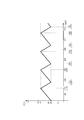
- the inside of the processing cabinet 10 and the inside of the freezer 2 become ⁇ 60 ° C. Thereafter, when the operation is stopped, the temperature rises and reaches ⁇ 25 ° C. in 3 hours (180 minutes) as shown in FIG. At this time, the refrigeration operation is resumed (ON) by the control device when the temperature reaches around ⁇ 25 ° C., and reaches ⁇ 60 ° C. in 40 minutes. When the temperature reaches ⁇ 60 ° C., the control device stops the refrigeration operation (OFF). In this way, by performing the operation for 40 minutes every 3 hours, the inside of the processing chamber 10 and the inside of the freezer 2 of the quick freezing apparatus 1 is maintained at ⁇ 25 ° C.
- the object to be cooled Q is stored in the refrigeration chamber 11 of the quick freezing apparatus 1 to be in a refrigerated state, depending on the type of the object to be cooled Q, it basically operates for more than 40 minutes, -60 ° C is maintained.
- the ice temperature chamber 3 operates the ice temperature fan F8 for 3 to 5 minutes every hour, takes out the second cold air Y2 in the freezer 2 and raises the temperature by the ice temperature temperature adjusting means 5. Then, when introduced into the ice temperature chamber 3 as the cold air Ya for ice temperature, -4 ° C. to 0 ° C. was maintained. Further, the refrigerator 4 operates the refrigeration fan F9 for about 10 minutes every hour, takes out the third cold air Y3 in the ice temperature storage 3, and raises the temperature by the temperature control means 6 for refrigeration. When it was introduced into the refrigerator 4 as cold air Yb, 4 ° C. to 8 ° C. was maintained. As shown in FIG.
- a popular type quick freezing apparatus 1 having a cooling capacity of ⁇ 45 ° C. provided with a cooling heat exchanger 12 and a cold air blowing fan 13 near one wall of the refrigeration processing chamber 11, and an internal capacity of and freezer 2 to about 15 m 3, the ice temperature chamber 3 of the internal volume of approximately 12m 3, and a refrigerator 4 internal volume of about 15 m 3, a device coupled to serial manner.
- the operating conditions explain.
- the quick freezing apparatus 1 when the quick freezing apparatus 1 is operated to set the inside of the processing cabinet 10 and the inside of the freezer 2 to ⁇ 45 ° C., and then the operation is stopped, the temperature rises as shown in FIG. 120 minutes), the temperature reaches ⁇ 25 ° C.
- the refrigeration operation is resumed (ON) by the control device at around -25 ° C, and reaches -45 ° C in 1 hour (60 minutes).
- the control device stops the refrigeration operation (OFF). In this way, by performing the operation for one hour every two hours, the inside of the processing chamber 10 and the freezer 2 of the quick freezing apparatus 1 is maintained at ⁇ 25 ° C. to ⁇ 45 ° C.
- the ice temperature chamber 3 operates the ice temperature fan F8 every hour for 5 to 7 minutes, takes out the second cold air Y2 in the freezer 2 and raises the temperature by the ice temperature temperature adjusting means 5.
- the temperature was maintained at -4 ° C to 0 ° C.
- the refrigerator 4 operates the refrigeration fan F9 for about 10 to 12 minutes every hour, takes out the third cold air Y3 in the ice temperature storage 3, and raises the temperature by the temperature control means 6 for refrigeration, When introduced into the refrigerator 4, 4 ° C. to 8 ° C. was maintained.
- the refrigeration fan F9 When the freezer 2 and the refrigerator 4 are connected in communication, the refrigeration fan F9 is operated for 2 to 3 minutes every hour, the second cold air Y2 in the freezer 2 is taken out, and the temperature control means 6 for refrigeration is used. When the temperature was raised and introduced into the refrigerator 4, 4 ° C. to 8 ° C. was maintained.
- the above-mentioned 1st Example and 2nd Example are an example, Comprising: Each numerical value is based on the magnitude
- the storage in the ice warm storage 3 was evaluated as having basically improved quality in all aspects compared to before storage.
- the case of fish was remarkable, followed by meat.
- Vegetables and fruits varied according to the type, but there was no evaluation that the quality was degraded.
- this result was a result which is not inferior even if it compares with the result of the evaluation test similarly implemented using the ice warmer apparatus of the certain famous manufacturer marketed.
- the design of the present invention can be changed.
- the processing chamber 10 having the freezing processing chamber 11, the freezer 2 having the freezing storage chamber 21, and the ice warming chamber 3 having the ice temperature storage chamber 31 are shown.
- the refrigerator 4 having the refrigerated storage room 41 is illustrated as being separated from the refrigerator 4, but may be provided integrally.
- a storage / cooling heat exchanger for cooling the inside of the refrigerated storage chamber 21 may be provided so that the exhaust heat of the outdoor unit is sent to the exhaust heat transfer pipe section 16. That is, each of the temperature adjusting means 5 and 6 may be configured to increase the temperature by using the exhaust heat of the storage and cooling heat exchanger of the freezer 2.
- the quick freezing apparatus 1 may have a configuration other than the above-described configuration or the illustrated configuration.
- the refrigeration fan F7, the ice temperature fan F8, and the refrigeration fan F9 can be arranged and arranged in any number of locations, such as piping and inside / outside, as long as cold air can be fed.
- the size and shape of the processing chamber 10, the freezer 2, the ice temperature storage 3, and the refrigerator 4 may be any shape and may be a warehouse type that allows workers to enter and exit.
- refrigeration may be a temperature range of ⁇ 18 ° C. or lower.
- the ice temperature may be in the temperature range of ⁇ 4 ° C. or more and 0 ° C. or less, but more preferably in the temperature range of ⁇ 2 ° C. or more and 0 ° C. or less.
- Refrigeration should just be a temperature range of 2 to 10 degreeC.
- the coupled low-temperature region cooling device of the present invention is a quick refrigeration provided with the cooling heat exchanger 12 and the cold air blowing fan 13 for cooling the refrigeration processing chamber 11 in which the object Q to be cooled is accommodated.
- the object Q to be cooled can be stored with high quality.
- a wide variety of foods and foods to be cooled Q can be stored at high quality and at low cost.
- Ingredients and foods suitable for freezing storage, foods and foods suitable for ice temperature storage, and foods and foods suitable for refrigeration storage can be efficiently stored.
- various foods and foods can be stored at an optimal low temperature range. For example, if the article Q to be cooled is stored at an ice temperature of ⁇ 4 ° C. to 0 ° C., the number of breeding bacteria is significantly less than that when stored at 2 ° C. to 4 ° C. for sanitation.
- the temperature control means 5 for ice temperature is comprised so that 2nd cold air Y2 may be heated up with external air S2 in the freezing operation stop state of the quick freezing apparatus 1, the rapid freezing apparatus 1 which is not operating is rapidly operated. Even when the freezing process is not performed, the temperature of the second cold air Y2 can be efficiently increased without consuming a large amount of energy.
- the ice temperature control means 5 is configured to raise the temperature of the second cold air Y2 by the ice temperature electric heater 59 or the ice temperature hot water storage tank 58 when the freezing operation of the quick refrigeration apparatus 1 is stopped. Therefore, it is suitable for use in cold districts where the outside air S2 is 0 ° C. or less or in winter.
- the humidifier 37 for increasing the humidity in the ice temperature storage 3 since the humidifier 37 for increasing the humidity in the ice temperature storage 3 is provided, the moisture of the object Q to be cooled stored at the ice temperature is not evaporated, and drying is prevented. It can be stored for a long time while maintaining its gloss. While improving the umami and sugar content (while aging), the reproduction of bacteria is suppressed, and a safe and delicious object Q to be cooled is obtained. The value of the product can be increased compared with that prior to storage at ice temperature.
- the entire device can store various foods and foods at various low temperatures.
- the temperature control means 6 for refrigeration for heating up the 2nd cold air Y2 taken out from the freezer 2 and the refrigerator 4 cooled by the cold air Yb heated by the temperature control means 6 for refrigeration are provided. Therefore, refrigerated storage of the object Q to be cooled can be performed with energy efficiency.
- the entire device can store various foods and foods at various low temperatures.
Landscapes
- Engineering & Computer Science (AREA)
- Chemical & Material Sciences (AREA)
- Combustion & Propulsion (AREA)
- Physics & Mathematics (AREA)
- Mechanical Engineering (AREA)
- Thermal Sciences (AREA)
- General Engineering & Computer Science (AREA)
- Devices That Are Associated With Refrigeration Equipment (AREA)
- Cold Air Circulating Systems And Constructional Details In Refrigerators (AREA)
Abstract
急速冷凍装置と冷凍庫と氷温庫を個別に導入や運転させる必要がなく、導入コストを軽減できると共に、主として急速冷凍装置を作動させることで冷凍庫及び氷温庫の運転コストも軽減可能な連結式低温域別冷却装置を提供するために、被冷却物Qが収容される冷凍処理室11を冷却するための冷却用熱交換器12及び冷気送風ファン13を備えた急速冷凍装置1と、冷凍処理室11から取り出した第1冷気Y1によって冷却される冷凍庫2と、冷凍庫2内から取り出した第2冷気Y2を昇温するための氷温用温調手段5と、氷温用温調手段5にて昇温された冷気Yaによって冷却される氷温庫3と、を具備し、氷温用温調手段5は、急速冷凍装置1の排熱S1によって第2冷気Y2を昇温するように構成している。
Description
本発明は、連結式低温域別冷却装置に関する。
現在、食材や加工食品の長期保存は、一部を除いて冷却による管理が主流である。そして、出来うる限り本来の姿のままに(色調、味、香り、食感等を劣化させずに)保存するために、食材等の被冷却物の種類や保存期間を鑑みて、冷凍、氷温、冷蔵、と使い分けているのが現状である。特に、冷却業務に於ては、冷凍法が主流となっており、品質を保つ上で急速冷凍技術が欠かせない存在となっている。例えば、本発明者等は、冷却用熱交換器を冷凍処理室の中央に設置して連続的に効率良く急速冷凍が出来うる急速冷凍装置を提案した(特許文献1参照)。また、磁気エネルギーを利用した急速冷凍装置(特許文献2参照)が公知である。
しかし、従来の急速冷凍装置は、基本的に冷凍物を品質良く生産する装置であることに変わりない。従って、製造した冷凍物を保管する冷凍庫(冷凍倉庫)を別個に設置しなければならない。つまり、急速冷凍装置と冷凍庫とを、夫々、独立して、運転させていたため、多大なエネルギーが必要になるといった問題があった。
また、最近は、冷凍保存に不向きな果物や野菜類の長期保存と品質向上のために、氷温保存が注目されるなど、冷却保存の分野にも多様化が進んでいる。
従って、現在の豊かな食生活には、生鮮食材や食品の種類や状況によって、氷温庫も必要不可欠なものになりつつあり、冷却業者にとっては氷温庫(氷温倉庫)の導入(設置)も急務となっている。
また、最近は、冷凍保存に不向きな果物や野菜類の長期保存と品質向上のために、氷温保存が注目されるなど、冷却保存の分野にも多様化が進んでいる。
従って、現在の豊かな食生活には、生鮮食材や食品の種類や状況によって、氷温庫も必要不可欠なものになりつつあり、冷却業者にとっては氷温庫(氷温倉庫)の導入(設置)も急務となっている。
そこで、本発明は、急速冷凍装置と冷凍庫と氷温庫を個別に導入や運転させる必要がなく、導入コストを軽減できると共に、主として急速冷凍装置を作動させることで冷凍庫及び氷温庫の運転コスト(エネルギー消費)も軽減可能な連結式低温域別冷却装置の提供を目的とする。
上記目的を達成するために、本発明の連結式低温域別冷却装置は、被冷却物が収容される冷凍処理室を冷却するための冷却用熱交換器及び冷気送風ファンを備えた急速冷凍装置と、上記冷凍処理室から取り出した第1冷気によって冷却される冷凍庫と、該冷凍庫内から取り出した第2冷気を昇温するための氷温用温調手段と、該氷温用温調手段にて昇温された冷気によって冷却される氷温庫と、を具備し、上記氷温用温調手段は、上記急速冷凍装置の排熱によって上記第2冷気を昇温するように構成しているものである。
また、上記氷温用温調手段は、上記急速冷凍装置の冷凍運転停止状態において上記第2冷気を外気によって昇温するように構成しているものである。
また、上記氷温用温調手段は、上記急速冷凍装置の冷凍運転停止状態において上記第2冷気を氷温用電気ヒータ又は氷温用貯湯槽によって昇温するように構成しているものである。
また、上記氷温庫内の湿度を高めるための加湿器を具備するものである。
また、上記氷温庫内から取り出した第3冷気を昇温するための冷蔵用温調手段と、該冷蔵用温調手段にて昇温された冷気によって冷却される冷蔵庫と、を具備するものである。
または、上記冷凍庫内から取り出した上記第2冷気を昇温するための冷蔵用温調手段と、該冷蔵用温調手段にて昇温された冷気によって冷却される冷蔵庫と、を具備するものである。
本発明によれば、被冷却物の冷凍処理、冷凍保存、氷温保存を、エネルギー効率良く行うことができる。様々な食材や食品を効率良く、かつ、食材や食品を最適な冷却状態で保存できる。
以下、図示の実施形態に基づき本発明を詳説する。
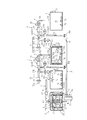
本発明に係る連結式低温域別冷却装置は、図1乃至図3に示すように、食材や食品等の被冷却物Qを収容して冷凍処理するための冷凍処理室11を有する急速冷凍装置1と、被冷却物Qを冷凍保存するための冷凍庫2と、被冷却物Qを氷温保存するための氷温庫3と、被冷却物Qを冷蔵保存するための冷蔵庫4と、を備えている。
本発明に係る連結式低温域別冷却装置は、図1乃至図3に示すように、食材や食品等の被冷却物Qを収容して冷凍処理するための冷凍処理室11を有する急速冷凍装置1と、被冷却物Qを冷凍保存するための冷凍庫2と、被冷却物Qを氷温保存するための氷温庫3と、被冷却物Qを冷蔵保存するための冷蔵庫4と、を備えている。
そして、冷凍処理室11と冷凍庫2とを連通連結するための冷凍用連結配管部7を備えている。冷凍用連結配管部7は、冷凍処理室11から冷凍用ファンF7にて第1冷気Y1を取り出して、冷凍庫2内の冷凍貯蔵室21へ導入するように設けている。つまり、冷凍処理室11から取り出した第1冷気Y1によって冷凍貯蔵室21を冷却するように構成している。また、冷凍用連結配管部7は、第1冷気取出流量を調整可能(開閉可能)な冷凍用弁部V7を備えている。
さらに、冷凍庫2と氷温庫3とを連通連結する氷温用連結配管部8と、氷温用連結配管部8の氷温用ファンF8にて冷凍貯蔵室21から取り出した第2冷気Y2を昇温するための氷温用温調手段5と、を備えている。
氷温用連結配管部8は、氷温用温調手段5にて昇温された冷気(氷温用冷気)Yaを氷温庫3内へ導入して、氷温貯蔵室31を冷却するように構成している。
氷温用連結配管部8は、氷温用温調手段5にて昇温された冷気(氷温用冷気)Yaを氷温庫3内へ導入して、氷温貯蔵室31を冷却するように構成している。
先ず、急速冷凍装置1は、被冷却物Qを収容する冷凍処理室11と、冷凍処理室11を冷却するための冷却用熱交換器12及び複数の冷気送風ファン13,13と、冷却用熱交換器12に接続された室外機15と、を備えている。
冷却用熱交換器(冷媒蒸発器)12は、冷凍処理室11の左右方向の中央部に仕切り壁状に配設され、冷凍処理室11を、第1冷凍区画11aと、第2冷凍区画11bと、に二分割している。そして、冷却用熱交換器12は、一方面12a側から他方面12b側、及び、他方面12b側から一方面12a側へ、空気(冷気)が送流可能な形状である。また、冷却用熱交換器12は、周囲の空気を冷却して冷気を発生させるものであり、内部に冷媒ガス等の冷却用媒体が送流している。そして、冷却用熱交換器12は、冷凍処理室11を内有する処理庫10の外部に配設された室外機15に接続されている。
室外機15は、冷却用媒体を圧縮するためのコンプレッサ(圧縮器)と、圧縮した冷媒を冷やすためのラジエータ等の室外熱交換器(凝縮器やファン)と、冷却した圧縮冷媒を膨張させるための膨張器(弁)等を備え、急速冷凍装置1の冷凍処理運転中において、外気温度よりも高い排熱(排気)S1を放出する。
また、複数の冷気送風ファン13,13は、第1冷凍区画11aを介して冷却用熱交換器12の一方面12aと対面状に配設される第1の冷気送風ファン13Aと、第2冷凍区画11bを介して冷却用熱交換器12の他方面12bと対面状に配設される第2の冷気送風ファン13Bと、を備えている。冷気送風ファン13は、制御装置によってファン回転方向を正転・逆転に制御され、送風方向を変更可能である。そして、第1の冷気送風ファン13Aと第2の冷気送風ファン13Bのファン回転方向が、制御装置によって、冷気を第1冷凍区画11aから第2冷凍区画11bへの流れ(矢印K方向)と、冷気を第2冷凍区画11bから第1冷凍区画11aへの流れとに、所定時間毎に切り換わるように、制御される。
また、処理庫10は冷気循環用流路14を有している。
冷気循環用流路14は、第1の冷気送風ファン13Aの反冷凍区画側と、第2の冷気送風ファン13Bの反冷凍区画側と、を接続して、第1・2の冷気送風ファン13A,13Bによって、矢印K方向(図1と図3参照)の冷気流れを発生させる際に第2の冷気送風ファン13Bによって吹き出される冷気を第1の冷気送風ファン13Aの吸込み側へ送るための流路である。また、図示省略するが、第1・2冷気送風ファン13A,13Bが矢印K方向と反対方向の冷気流れを発生させる際に、第1の冷気送風ファン13Aによって吹き出される冷気を第2の冷気送風ファン13Bの吸込み側へ送るための流路である。
冷気循環用流路14は、第1の冷気送風ファン13Aの反冷凍区画側と、第2の冷気送風ファン13Bの反冷凍区画側と、を接続して、第1・2の冷気送風ファン13A,13Bによって、矢印K方向(図1と図3参照)の冷気流れを発生させる際に第2の冷気送風ファン13Bによって吹き出される冷気を第1の冷気送風ファン13Aの吸込み側へ送るための流路である。また、図示省略するが、第1・2冷気送風ファン13A,13Bが矢印K方向と反対方向の冷気流れを発生させる際に、第1の冷気送風ファン13Aによって吹き出される冷気を第2の冷気送風ファン13Bの吸込み側へ送るための流路である。
急速冷凍装置1の冷凍運転状態においては、冷凍処理室11及び冷気循環用流路14は、冷却用熱交換器12や冷気送風ファン13等によって、冷気(内部温度)が、例えば-60℃~-25℃に冷却保持される。
そして、冷気循環用流路14に、冷凍用連結配管部7の取出口を接続し、冷凍処理室11内の第1冷気Y1を冷凍用ファンF7にて取り出し可能としている。
取り出した第1冷気Y1は冷凍用連結配管部7によって冷凍庫2内に導入される。
第1冷気Y1によって、冷凍貯蔵室21内の冷気(第2冷気Y2)は、所定冷凍温度域(例えば、-60℃~-25℃)に保持される。
冷凍貯蔵室21は、急速冷凍装置1にて冷凍処理した被冷却物Qを冷凍状態(冷凍物)として保存している。
また、冷凍庫2は、送られてくる第1冷気Y1によって、冷凍庫2内(冷凍貯蔵室21)の気圧(内圧)が高くなった場合に、冷気を外部へ逃がして気圧を調整するために冷凍用調圧弁部22を備えている。
取り出した第1冷気Y1は冷凍用連結配管部7によって冷凍庫2内に導入される。
第1冷気Y1によって、冷凍貯蔵室21内の冷気(第2冷気Y2)は、所定冷凍温度域(例えば、-60℃~-25℃)に保持される。
冷凍貯蔵室21は、急速冷凍装置1にて冷凍処理した被冷却物Qを冷凍状態(冷凍物)として保存している。
また、冷凍庫2は、送られてくる第1冷気Y1によって、冷凍庫2内(冷凍貯蔵室21)の気圧(内圧)が高くなった場合に、冷気を外部へ逃がして気圧を調整するために冷凍用調圧弁部22を備えている。
急速冷凍装置1の冷凍運転停止状態においては、冷凍庫2内の温度は徐々に上昇し始めるが、冷凍庫用センサによって、冷凍貯蔵室21内が、所定冷凍上限温度(例えば、-25℃よりも僅かに低い温度)であることを検知すれば、そのセンサが送信した冷凍上限温度検知信号を、制御装置が受信して、急速冷凍装置1を作動(ON)させる。
そして、冷凍庫用センサが所定冷凍下限温度(例えば、-60℃)を検知すれば、冷凍下限温度検知信号を受信した制御装置が急速冷凍装置1を停止(OFF)させる。
このような急速冷凍装置1のON-OFFを制御装置が繰り返し行って、冷凍庫2内は所定冷凍温度域に保持される。なお、急速冷凍装置1の運転中に、随時、被冷却物Qを冷凍処理室11に収容させ、冷凍物を次々と生産すれば無駄が生じない。
そして、冷凍庫用センサが所定冷凍下限温度(例えば、-60℃)を検知すれば、冷凍下限温度検知信号を受信した制御装置が急速冷凍装置1を停止(OFF)させる。
このような急速冷凍装置1のON-OFFを制御装置が繰り返し行って、冷凍庫2内は所定冷凍温度域に保持される。なお、急速冷凍装置1の運転中に、随時、被冷却物Qを冷凍処理室11に収容させ、冷凍物を次々と生産すれば無駄が生じない。
そして、氷温用連結配管部8は、氷温用ファンF8にて冷凍貯蔵室21から-60℃~-25℃の第2冷気Y2を取り出す。また、氷温用連結配管部8は、第2冷気取出流量(供給流量)を調整可能な氷温用弁部V8を備えている。
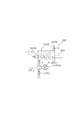
氷温用温調手段5は、急速冷凍装置1の排熱S1によって第2冷気Y2を昇温するように構成した氷温用排熱昇温手段50と、外気S2(図2参照)によって第2冷気Y2を昇温するように構成した氷温用外気取込手段55と、所定温度に加熱された湯によって氷温用連結配管部8を加熱して第2冷気Y2を昇温するための氷温用貯湯槽58と、氷温用連結配管部8を加熱して第2冷気Y2を昇温するための氷温用電気ヒータ(ニクロム線等の電熱線)59と、を備えている。
氷温用排熱昇温手段50は、急速冷凍装置1の室外機15の排熱(排気)S1が送流する排熱送流管部16と、排熱送流管部16と連通連結する氷温用排熱配管部51と、その氷温用排熱配管部51と氷温用連結配管部8とを連通連結させる氷温用排熱合流配管部52と、を備え、第2冷気Y2に直接に排熱S1を付与して(混合させて)昇温させる構成である。
或いは、氷温用排熱合流配管部52にかわって、図4に示すように、氷温用排熱配管部51を送流する排熱S1と、氷温用連結配管部8を送流する第2冷気Y2とが、非接触で(混合させずに)熱交換を行う氷温用熱交換配管部53を備えたものである。
氷温用熱交換配管部53は、氷温用排熱配管部51からの排熱S1が、氷温用連結配管部8の管外面に、直接接触して、熱交換が行われるように氷温用連結配管部8の一部を包囲するように構成すると共に、接触後の排熱S1が管外部に放出されるように構成している。
なお、図示省略するが、氷温用熱交換配管部53は、氷温用排熱配管部51からの排熱S1が導入されて送流する熱交換用配管部の管外面と、氷温用連結配管部8の管外面と、を接近乃至接触させて、熱交換が行われるように構成するも良い。また、図4に於ては、氷温用熱交換配管部53内に氷温用電気ヒータ59を内装して、消費電力を軽減する。
氷温用熱交換配管部53は、氷温用排熱配管部51からの排熱S1が、氷温用連結配管部8の管外面に、直接接触して、熱交換が行われるように氷温用連結配管部8の一部を包囲するように構成すると共に、接触後の排熱S1が管外部に放出されるように構成している。
なお、図示省略するが、氷温用熱交換配管部53は、氷温用排熱配管部51からの排熱S1が導入されて送流する熱交換用配管部の管外面と、氷温用連結配管部8の管外面と、を接近乃至接触させて、熱交換が行われるように構成するも良い。また、図4に於ては、氷温用熱交換配管部53内に氷温用電気ヒータ59を内装して、消費電力を軽減する。
図1乃至図4に示すように、氷温用排熱配管部51は、排熱S1が氷温用連結配管部8側(図1乃至図3の氷温用排熱合流配管部52側、又は、図4の氷温用熱交換配管部53側)と、氷温用排熱放出口部51b側と、の流れの切換えや、流量の調整(開閉量の調整)を行うための氷温用排熱弁部V51を有している。
例えば、氷温用排熱弁部V51は、第2冷気Y2を所定の温度に昇温するために不要となった(余剰な)排熱S1を管外部に放出するように作動する。また、氷温用連結配管部8側に排熱S1が流れるのを阻止するように作動する。
また、図1と図3に示すように、排熱送流管部16の排熱取込口16aは、室外機15の排気口から放出される排熱S1を効率良く集めて管内へ取り込めるようにラッパ形状とするのが好ましい。
例えば、氷温用排熱弁部V51は、第2冷気Y2を所定の温度に昇温するために不要となった(余剰な)排熱S1を管外部に放出するように作動する。また、氷温用連結配管部8側に排熱S1が流れるのを阻止するように作動する。
また、図1と図3に示すように、排熱送流管部16の排熱取込口16aは、室外機15の排気口から放出される排熱S1を効率良く集めて管内へ取り込めるようにラッパ形状とするのが好ましい。
図2に示すように、氷温用外気取込手段55は、氷温用連結配管部8内に外気S2を直接送り込んで第2冷気Y2を昇温させるように構成され、氷温用外気吸込口部55aと、氷温用外気吸込ファン55fと、氷温用外気吸込口部55aと氷温用連結配管部8とを連通連結させる氷温用外気合流配管部55bと、氷温用外気吸込口部55aと氷温用外気合流配管部55bとの間を開閉するための氷温用外気弁部V55と、を備えている。
氷温用外気取込手段55は、急速冷凍装置1が冷凍運転停止状態(排熱非放出状態)の場合に、制御装置によって氷温用外気弁部V55が開状態になると共に氷温用外気吸込ファン55fが回転して外気S2を吸込み、吸込んだ外気S2を、氷温用連結配管部8に導入させて、第2冷気Y2を昇温させる。
なお、急速冷凍装置1が冷凍処理運転状態(排熱放出状態)の場合であっても、外気S2と排気S1を併用して、第2冷気Y2の昇温を調整するも良い。
なお、急速冷凍装置1が冷凍処理運転状態(排熱放出状態)の場合であっても、外気S2と排気S1を併用して、第2冷気Y2の昇温を調整するも良い。
また、氷温用温調手段5は、氷温用連結配管部8内の第2冷気Y2の温度を測定するための氷温用基準温度センサと、昇温後の冷気Yaを測定するための氷温用確認温度センサと、氷温貯蔵室31の室温を測定する氷温室温度センサと、を備えている。
制御装置は、氷温貯蔵室31内が昇温して所定氷温上限温度(例えば、0℃よりも僅かに低い温度)になると、氷温用弁部V8を開き、氷温用ファンF8を作動させて、氷温用冷気Yaを氷温庫3内に導入させて、氷温庫3を所定氷温温度域(例えば、-4℃以上0℃以下)に保持する。
氷温室温度センサが所定氷温下限温度(例えば、-4℃)を検知すれば、そのセンサが送信した氷温下限温度検知信号を、制御装置が受信して、氷温用弁部V8を閉じると共に氷温用ファンF8を停止させる。
また、制御装置は、外気温度センサによって外気温度が0℃以下(零下)を検知した場合は、氷温用外気取込手段55を制御して、零下の外気S2を、第2冷気Y2に変わって、或いは、第2冷気Y2と共に、氷温用連結配管部8に導入させ、その後、氷温用外気取込手段55以外の氷温用温調手段5にて昇温して氷温用冷気Yaとして氷温庫3へ導入する。また、氷温庫3は、送られてくる氷温用冷気Yaによって、氷温庫3内の気圧(内圧)が高くなった場合に、冷気を外部へ逃がして気圧を調整するために氷温用調圧弁部32を備えている。
氷温は、食材や食品等の被冷却物Q(の細胞)が凍り始める直前の温度であり、氷温貯蔵室31に貯蔵される被冷却物Qは、常温状態(生鮮状態)で収容された後、未凍結(非凍結)状態となって保存される。
被冷却物Qを未凍結の温度域(氷温域)で冬眠状態にすることができ、呼吸代謝が抑制され老化の進行が遅くなり細胞の活性化が保たれ生鮮物では常温(室温)の3~5倍の鮮度が保持可能である。
また、細胞は、0℃以下のストレスにさらされると、凍るまいとする自己防衛(生物防衛反応)の結果、不凍液を蓄える。この不凍液に含まれる糖や遊離アミノ酸は旨み成分でもあり、これにより旬の味が形成される。また、食感の向上、例えば、まろやかさや、しっとり感、粘りや弾力性等、物性面での旨みを増進、熟成が進む。
即ち、食品素材のもつ本来の旨みを十分に生かすことができる。これらの事実は、古来から経験的に大寒仕込みとして干物や野菜、漬物等の保存で旨味を引き出すことで知られている。
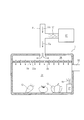
そして、氷温庫3は、図1乃至図4に於て、二重壁冷却構造であって、氷温貯蔵室31を形成する室内壁部33(天井壁部33aと床壁部33bと内側壁部33cと)と、室外壁部35(上壁部35aと底壁部35bと外側壁部35c)と、を有している。
そして、室内壁部33と室外壁部35の間に、氷温用連結配管部8の吐出口を連通させて氷温用冷気Yaを送流させ、氷温貯蔵室31を冷却するように構成している。
室外壁部35は、3層の断熱性部材で構成され、外側から順に、断熱材パネル層、発泡スチロール層、断熱材パネル層、を有している。室内壁部33は伝熱性部材(良電熱性部材)で構成される。
そして、室内壁部33と室外壁部35の間に、氷温用連結配管部8の吐出口を連通させて氷温用冷気Yaを送流させ、氷温貯蔵室31を冷却するように構成している。
室外壁部35は、3層の断熱性部材で構成され、外側から順に、断熱材パネル層、発泡スチロール層、断熱材パネル層、を有している。室内壁部33は伝熱性部材(良電熱性部材)で構成される。
また、図5に示す氷温庫3の他例は、一重壁冷却構造型のシャワー型冷却構造であって、氷温貯蔵室31の天井側で氷温用冷気Yaを拡散させ、複数の吹き出し孔39,39を介して、氷温貯蔵室31内に直接吐出させて冷却するように構成している。
なお、シャワー型冷却構造は、天井裏(天井側)に冷気拡散室38を設け、冷気拡散室38と氷温貯蔵室31を仕切る天井壁部33aに複数の吹き出し孔39,39を貫設した構造である。
図示省略するが、シャワー型冷却構造の別例として、スプリンクラー配管のように、天井側に網の目状の冷気拡散配管部を設け、冷気拡散配管部に複数の吹き出し孔39を貫設した構造とするも良い。
なお、シャワー型冷却構造は、天井裏(天井側)に冷気拡散室38を設け、冷気拡散室38と氷温貯蔵室31を仕切る天井壁部33aに複数の吹き出し孔39,39を貫設した構造である。
図示省略するが、シャワー型冷却構造の別例として、スプリンクラー配管のように、天井側に網の目状の冷気拡散配管部を設け、冷気拡散配管部に複数の吹き出し孔39を貫設した構造とするも良い。
さらに、図1乃至図3と図5に示すように、氷温貯蔵室31内の湿度を高めるための加湿器37を氷温貯蔵室31内に備えている。
氷温貯蔵室31内は、加湿器37によって、湿度が90%~100%に調湿(保持)されている。
加湿器37は、貯液ケース部内の水等の液体を、圧電セラミックス等の振動子によってミスト化(霧化)し、放出口からミストMを放出する超音波式のものである。
氷温貯蔵室31内は、加湿器37によって、湿度が90%~100%に調湿(保持)されている。
加湿器37は、貯液ケース部内の水等の液体を、圧電セラミックス等の振動子によってミスト化(霧化)し、放出口からミストMを放出する超音波式のものである。
また、図5に示すように、氷温用冷気Yaを氷温貯蔵室31内に直接導入して冷却する場合は、氷温用連結配管部8と、加湿器37のミスト放出口と、を連通連結して、氷温用冷気YaにミストMを直接付与して(混合させて)、氷温貯蔵室31内へ導入させ、室内の湿度を高めるように構成するも良い。
制御装置は、氷温貯蔵室31内に設けた湿度センサが測定した湿度データに基づいて、加湿器37のミスト噴霧量を制御して、調湿を行う。
制御装置は、氷温貯蔵室31内に設けた湿度センサが測定した湿度データに基づいて、加湿器37のミスト噴霧量を制御して、調湿を行う。
さらに、図示省略するが、氷温貯蔵室31に、シャーベット状の氷と、冷却した塩水と、を混合した塩分を有するスラリーアイスを、貯蔵して、氷温貯蔵室31の温度上昇を抑制すると共に被冷却物Qの冷却を補助するように構成する。
また、氷温貯蔵室31を複数の貯蔵区画(小室)に分割し、その貯蔵区画の1つ又は複数に、塩分を有するスラリーアイスを収容するも良い。
なお、スラリーアイスは、塩分濃度が0.5%~5%、好ましくは1%~2%で、温度を-2℃~-0.5℃とするのが望ましい。
また、氷温貯蔵室31を複数の貯蔵区画(小室)に分割し、その貯蔵区画の1つ又は複数に、塩分を有するスラリーアイスを収容するも良い。
なお、スラリーアイスは、塩分濃度が0.5%~5%、好ましくは1%~2%で、温度を-2℃~-0.5℃とするのが望ましい。
このように、氷温貯蔵室31の温度と湿度を管理することで、被冷却物Qの旨味や糖度が向上し(低温で熟成され)、また、被冷却物Qの水分の蒸散を防止して、みずみずしさや、色や艶を保持できる(皺を防止できる)。また、細菌(雑菌)の繁殖を抑え、衛生的に長期保存できる。
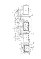
さらに、図1と図2に示すように、氷温庫3と冷蔵庫4を連通連結する冷蔵用連結配管部9と、冷蔵用連結配管部9の冷蔵用ファンF9にて氷温庫3内から取り出した第3冷気Y3を昇温するための冷蔵用温調手段6と、を備えている。
冷蔵用連結配管部9は、冷蔵用温調手段6にて昇温された冷気(冷蔵用冷気)Ybを冷蔵庫4内へ導入して、冷蔵貯蔵室41を冷却するように構成している。
言い換えると、処理庫10と冷凍庫2と氷温庫3と冷蔵庫4とを直列状に連結した構成である。
冷蔵用連結配管部9は、冷蔵用温調手段6にて昇温された冷気(冷蔵用冷気)Ybを冷蔵庫4内へ導入して、冷蔵貯蔵室41を冷却するように構成している。
言い換えると、処理庫10と冷凍庫2と氷温庫3と冷蔵庫4とを直列状に連結した構成である。
図3に示す他の実施形態は、冷蔵用連結配管部9の取出口を、冷凍庫2と連通連結して、冷蔵用ファンF9にて冷凍庫2内から取り出した第2冷気Y2を冷蔵用温調手段6にて昇温して、冷蔵用冷気Ybとして、冷蔵庫4内に導入するように構成している。
言い換えると、冷凍庫2に、氷温庫3と冷蔵庫4と並列状に連結した構成である。
言い換えると、冷凍庫2に、氷温庫3と冷蔵庫4と並列状に連結した構成である。
図1乃至図3に示すように、冷蔵用温調手段6は、氷温用温調手段5と同様の構成であるが、昇温させる温度は異なり、氷温用冷気Yaよりも温度の高い冷蔵用冷気Ybをつくるためのものである。
冷蔵用温調手段6は、冷蔵用排熱昇温手段60と、冷蔵用外気取込手段65と、冷蔵用貯湯槽68と、冷蔵用電気ヒータ69と、を備えている。
冷蔵用排熱昇温手段60は、排熱送流管部16と、排熱送流管部16と連通連結する冷蔵用排熱配管部61と、冷蔵用排熱合流配管部62と、を備えている。
或いは、冷蔵用排熱合流配管部62にかわって、図4に示すように冷蔵用熱交換配管部63を備えたものである。冷蔵用熱交換配管部63は、排熱S1が冷蔵用連結配管部9の管外面に直接接触、又は、排熱S1が送流する熱交換用配管部の管外面と、冷蔵用連結配管部9の管外面とを、接近乃至接触させて熱交換が行われるように構成したもののいずれであっても良い。
図1乃至図3に示すように、冷蔵用排熱配管部61は、冷蔵用排熱弁部V61と、冷蔵用排熱送流ファン61fと、冷蔵用排熱放出ファン61eと、冷蔵用排熱放出口部61bを有している。また、冷蔵用外気取込手段65は、冷蔵用外気吸込口部65aと、冷蔵用外気吸込ファン65fと、冷蔵用外気弁部V65と、冷蔵用外気合流配管部65bと、を備えている。
また、冷蔵用温調手段6は、図1と図2に於ては第3冷気Y3を、図3に於ては第2冷気Y2を、測定するための冷蔵用基準温度センサと、昇温後の冷気(冷蔵用冷気)Ybを測定するための冷蔵用確認温度センサと、冷蔵貯蔵室41の室温を測定する冷蔵室温度センサと、を備えている。
また、冷蔵用連結配管部9は、図1と図2に於ては第3冷気Y3の、図3に於ては第2冷気Y2の、取出流量(供給流量)を調整可能な冷蔵用弁部V9を備えている。
制御装置は、冷蔵貯蔵室41内が昇温して所定冷蔵上限温度(例えば、8℃よりも僅かに低い温度)になると、冷蔵用弁部V9を開き、冷蔵用ファンF9を作動させて、冷蔵用冷気Ybを冷蔵庫4内に導入させて、冷蔵庫4を所定冷蔵温度域(例えば、4℃以上8℃以下)に保持する。
冷蔵室温度センサが所定氷温下限温度(例えば、4℃)を検知すれば、そのセンサが送信した冷蔵下限温度検知信号を、制御装置が受信して冷蔵用弁部V9を閉じると共に冷蔵用ファンF9を停止させる。
また、冷蔵用連結配管部9は、図1と図2に於ては第3冷気Y3の、図3に於ては第2冷気Y2の、取出流量(供給流量)を調整可能な冷蔵用弁部V9を備えている。
制御装置は、冷蔵貯蔵室41内が昇温して所定冷蔵上限温度(例えば、8℃よりも僅かに低い温度)になると、冷蔵用弁部V9を開き、冷蔵用ファンF9を作動させて、冷蔵用冷気Ybを冷蔵庫4内に導入させて、冷蔵庫4を所定冷蔵温度域(例えば、4℃以上8℃以下)に保持する。
冷蔵室温度センサが所定氷温下限温度(例えば、4℃)を検知すれば、そのセンサが送信した冷蔵下限温度検知信号を、制御装置が受信して冷蔵用弁部V9を閉じると共に冷蔵用ファンF9を停止させる。
また、制御装置及び冷蔵用温調手段6は、外気温度センサによって外気温度が零下(0℃以下)であることを検知した場合は、零下の外気S2を取り込むと共に昇温して冷蔵庫4に導入する。
また、冷蔵庫4は、送られてくる冷蔵用冷気Ybによって、冷蔵庫4内の気圧(内圧)が高くなった場合に、冷気を外部へ逃がして内圧を調整するために冷蔵用調圧弁部42を備えている。冷蔵庫4内は、冷蔵用温調手段6等によって、所定冷蔵温度域に保持される。
また、冷蔵庫4は、送られてくる冷蔵用冷気Ybによって、冷蔵庫4内の気圧(内圧)が高くなった場合に、冷気を外部へ逃がして内圧を調整するために冷蔵用調圧弁部42を備えている。冷蔵庫4内は、冷蔵用温調手段6等によって、所定冷蔵温度域に保持される。
また、各弁部、各ファン、各センサ等と命令信号や検知信号を送受信可能に電気的に有線又は無線で接続されている制御装置を備えている。
制御装置は、CPU(中央演算処理器)やシーケンサ等の演算部と、RAMやROM、フラッシュメモリ等の記憶部と、を有するコンピュータや制御盤である。
制御装置は、各センサの検知信号に基づいて、各弁部の開閉制御や流量制御、各ファンの回転数(流量)制御と停止制御、各ヒータや各貯湯層の温調制御を行う。
また、急速冷凍装置1の処理庫10と冷凍庫2と氷温庫3と冷蔵庫4には、断熱扉を各1箇所設け、外壁部は、断熱パネルと発泡スチロールと断熱パネルとを順次積層した3層構造である。
また、図示省略するが、排熱や冷気が送流する各配管部には、ゴミ等の異物や細菌やウイルス等を捕集(除去)可能なバグフィルターや集塵フィルタ等のフィルタ部を設けている。
ここで、図1乃至図3を用いて説明した実施形態に基づいて冷却能力が-60℃の急速冷凍装置1と、内部容量が21.87m3 の冷凍庫2と、内部容量が19.44m3 の氷温庫3と、内部容量が19.44m3 の冷蔵庫4と、を図1と図2のように直列状に連結したものを第1実施例とし、作動状況を説明する。なお、外気温は20℃である。
第1実施例は、急速冷凍装置1を2時間、冷凍運転すると処理庫10内及び冷凍庫2内は-60℃となる。その後、運転を停止すると、図6に示すように、温度が上昇し、3時間(180分)で-25℃となる。この際、-25℃近傍になると制御装置によって冷凍運転が再開(ON)され、40分で-60℃になる。-60℃になると制御装置にて冷凍運転が停止(OFF)される。このように、3時間毎に40分の運転を行うことで急速冷凍装置1の処理庫10内及び冷凍庫2内は、-25℃~-60℃に保持される。
なお、急速冷凍装置1の冷凍処理室11内に被冷却物Qを収容して冷凍状態にする場合は、被冷却物Qの種類によるが、基本的に40分を超えて運転し、その間は、-60℃が保持されることになる。
なお、急速冷凍装置1の冷凍処理室11内に被冷却物Qを収容して冷凍状態にする場合は、被冷却物Qの種類によるが、基本的に40分を超えて運転し、その間は、-60℃が保持されることになる。
そして、氷温庫3は、1時間毎に氷温用ファンF8を3分~5分作動させて、冷凍庫2内の第2冷気Y2を取り出して、氷温用温調手段5で昇温して、氷温用冷気Yaとして氷温庫3内に導入させれば、-4℃~0℃が保持された。
また、冷蔵庫4は、1時間毎に冷蔵用ファンF9を約10分作動させて、氷温庫3内の第3冷気Y3を取り出して、冷蔵用温調手段6で昇温して、冷蔵用冷気Ybとして冷蔵庫4内に導入させれば、4℃~8℃が保持された。
なお、図3に示すように、冷凍庫2と冷蔵庫4を連通連結した場合は、1時間毎に冷蔵用ファンF9を1~2分作動させて、冷凍庫2内の第2冷気Y2を取り出して、冷蔵用温調手段6で昇温して、冷蔵用冷気Ybとして冷蔵庫4内に導入させれば、4℃~8℃が保持された。
また、冷蔵庫4は、1時間毎に冷蔵用ファンF9を約10分作動させて、氷温庫3内の第3冷気Y3を取り出して、冷蔵用温調手段6で昇温して、冷蔵用冷気Ybとして冷蔵庫4内に導入させれば、4℃~8℃が保持された。
なお、図3に示すように、冷凍庫2と冷蔵庫4を連通連結した場合は、1時間毎に冷蔵用ファンF9を1~2分作動させて、冷凍庫2内の第2冷気Y2を取り出して、冷蔵用温調手段6で昇温して、冷蔵用冷気Ybとして冷蔵庫4内に導入させれば、4℃~8℃が保持された。
次に、図示省略するが冷凍処理室11の一方壁寄りに冷却用熱交換器12と冷気送風ファン13を設けて冷却能力を-45℃とした普及タイプの急速冷凍装置1と、内部容量が約15m3 の冷凍庫2と、内部容量が約12m3 の氷温庫3と、内部容量が約15m3 の冷蔵庫4と、を直列状に連結した装置を、第2実施例として、作動状況を説明する。
第2実施例は、急速冷凍装置1を運転して処理庫10内及び冷凍庫2内を-45℃とし、その後、運転を停止すると、図7に示すように、温度が上昇し、2時間(120分)で-25℃となる。-25℃近傍になると制御装置によって冷凍運転が再開(ON)され、1時間(60分)で-45℃になる。-45℃になると制御装置にて冷凍運転が停止(OFF)される。このように、2時間毎に1時間の運転を行うことで急速冷凍装置1の処理庫10内及び冷凍庫2内は、-25℃~-45℃に保持される。
そして、氷温庫3は、1時間毎に氷温用ファンF8を5分~7分作動させて、冷凍庫2内の第2冷気Y2を取り出して、氷温用温調手段5で昇温して、氷温庫3内に導入させれば、-4℃~0℃が保持された。
また、冷蔵庫4は、1時間毎に冷蔵用ファンF9を約10~12分作動させて、氷温庫3内の第3冷気Y3を取り出して、冷蔵用温調手段6で昇温して、冷蔵庫4内に導入させれば、4℃~8℃が保持された。
なお、冷凍庫2と冷蔵庫4を連通連結した場合は、1時間毎に冷蔵用ファンF9を2~3分作動させて、冷凍庫2内の第2冷気Y2を取り出して、冷蔵用温調手段6で昇温して、冷蔵庫4内に導入させれば、4℃~8℃が保持された。
なお、上述の第1実施例及び第2実施例は、一例であって、各数値は、急速冷凍装置1の大きさや冷却能力、及び、それに連結された各庫の大きさ(広さ)によって異なる。
次に、氷温庫3に保存する前の新鮮な状態の被冷却物Qと、第1実施例の氷温庫3に2ケ月間氷温保存した被冷却物Qとの、味、香り、食感について、5人の味の専門家による評価を行った。
保存前の状態を評価点4点として、その状態よりも優るものを5点とし、僅かに劣るものを3点、明らかに劣るものを2点、劣化が著しいものを1点としている。
結果を以下の表1に示す。
保存前の状態を評価点4点として、その状態よりも優るものを5点とし、僅かに劣るものを3点、明らかに劣るものを2点、劣化が著しいものを1点としている。
結果を以下の表1に示す。

表1から明らかなように、氷温庫3での保存は、保存前と比較して基本的に全ての面で品質が向上したとの評価を得た。
特に、魚の場合が顕著で、それに次いで肉類であった。野菜や果物は、種類によってバラツキはあるが、品質が劣化したという評価は無かった。
なお、この結果は、市販されている某有名メーカーの氷温庫装置を用いて同様に実施した評価試験の結果と比較しても、優るとも劣らない結果であった。
特に、魚の場合が顕著で、それに次いで肉類であった。野菜や果物は、種類によってバラツキはあるが、品質が劣化したという評価は無かった。
なお、この結果は、市販されている某有名メーカーの氷温庫装置を用いて同様に実施した評価試験の結果と比較しても、優るとも劣らない結果であった。
なお、本発明は、設計変更可能であって、図例では、冷凍処理室11を有する処理庫10と、冷凍貯蔵室21を有する冷凍庫2と、氷温貯蔵室31を有する氷温庫3と、冷蔵貯蔵室41を有する冷蔵庫4とを離間して図示しているが、一体状に設けても良い。図示省略するが、冷凍貯蔵室21内を冷却するための貯蔵冷却用熱交換器を設け、その室外機の排熱を、排熱送流管部16に送流するように設けても良い。つまり、各温調手段5,6は、冷凍庫2の貯蔵冷却用熱交換器の排熱を利用して昇温するように構成しても良い。急速冷凍装置1は上述の構成や図示の構成以外の構成とするも良い。
冷凍用ファンF7、氷温用ファンF8、冷蔵用ファンF9は、冷気を送流可能であれば、配管部や各庫内外等、配置や個数は自由である。また、処理庫10、冷凍庫2、氷温庫3、冷蔵庫4の大きさや形状は、自由であって、作業者が出入り可能な倉庫型であっても良い。なお、本発明において、冷凍とは、-18℃以下の温度域であれば良い。氷温とは、-4℃以上0℃以下の温度域であれば良いが、-2℃以上0℃以下の温度域とするのがより好ましい。冷蔵とは、2℃以上10℃以下の温度域であれば良い。
冷凍用ファンF7、氷温用ファンF8、冷蔵用ファンF9は、冷気を送流可能であれば、配管部や各庫内外等、配置や個数は自由である。また、処理庫10、冷凍庫2、氷温庫3、冷蔵庫4の大きさや形状は、自由であって、作業者が出入り可能な倉庫型であっても良い。なお、本発明において、冷凍とは、-18℃以下の温度域であれば良い。氷温とは、-4℃以上0℃以下の温度域であれば良いが、-2℃以上0℃以下の温度域とするのがより好ましい。冷蔵とは、2℃以上10℃以下の温度域であれば良い。
以上のように、本発明の連結式低温域別冷却装置は、被冷却物Qが収容される冷凍処理室11を冷却するための冷却用熱交換器12及び冷気送風ファン13を備えた急速冷凍装置1と、冷凍処理室11から取り出した第1冷気Y1によって冷却される冷凍庫2と、冷凍庫2内から取り出した第2冷気Y2を昇温するための氷温用温調手段5と、氷温用温調手段5にて昇温された冷気Yaによって冷却される氷温庫3と、を具備し、氷温用温調手段5は、急速冷凍装置1の排熱S1によって第2冷気Y2を昇温するように構成しているので、被冷却物Qの冷凍処理、冷凍保存、氷温保存を、エネルギー効率良く行うことができる。被冷却物Qを高品質に保管できる。多種多様な食材・食品等の被冷却物Qを高品質かつ低コストで保存できる。冷凍保存に適した食材・食品と、氷温保存に適した食材・食品と、冷蔵保存に適した食材・食品を、効率良く保存できる。つまり、様々な食材・食品を最適な低温域で保存できる。例えば、被冷却物Qを、-4℃~0℃の氷温で保存すると、2℃~4℃の冷蔵保存した場合に比べて、細菌の繁殖数が大幅に少なく衛生的である。
また、氷温用温調手段5は、急速冷凍装置1の冷凍運転停止状態において第2冷気Y2を外気S2によって昇温するように構成しているので、急速冷凍装置1を運転していない急速冷凍処理を行っていない場合であっても、第2冷気Y2の昇温を、エネルギーを大量に消費せずに効率良く行うことができる。
また、上記氷温用温調手段5は、急速冷凍装置1の冷凍運転停止状態において第2冷気Y2を氷温用電気ヒータ59又は氷温用貯湯槽58によって昇温するように構成しているので、外気S2が0℃以下のような寒冷地や冬期の使用において好適である。
また、氷温庫3内の湿度を高めるための加湿器37を具備するので、氷温貯蔵される被冷却物Qの水分が蒸散されず、乾燥を防止して、被冷却物Qの色や艶を保持したまま、長期間保存できる。旨味や糖度を向上させつつ(熟成させつつ)細菌の繁殖を抑制して、安全で美味しい被冷却物Qが得られる。氷温保存する前よりも商品価値を高めることができる。
また、氷温庫3内から取り出した第3冷気Y3を昇温するための冷蔵用温調手段6と、冷蔵用温調手段6にて昇温された冷気Ybによって冷却される冷蔵庫4と、を具備するので、被冷却物Qの冷蔵保存を、エネルギー効率良く行うことができる。装置全体として様々な食材・食品を様々な低温域で保存できる。
また、冷凍庫2内から取り出した第2冷気Y2を昇温するための冷蔵用温調手段6と、冷蔵用温調手段6にて昇温された冷気Ybによって冷却される冷蔵庫4と、を具備するので、被冷却物Qの冷蔵保存を、エネルギー効率良く行うことができる。装置全体として様々な食材・食品を様々な低温域で保存できる。
1 急速冷凍装置
2 冷凍庫
3 氷温庫
4 冷蔵庫
5 氷温用温調手段
6 冷蔵用温調手段
11 冷凍処理室
12 冷却用熱交換器
13 冷気送風ファン
37 加湿器
58 氷温用貯湯槽
59 氷温用電気ヒータ
Q 被冷却物
S1 排熱
S2 外気
Y1 第1冷気
Y2 第2冷気
Y3 第3冷気
Ya 氷温用温調手段にて昇温された冷気
Yb 冷蔵用温調手段にて昇温された冷気
2 冷凍庫
3 氷温庫
4 冷蔵庫
5 氷温用温調手段
6 冷蔵用温調手段
11 冷凍処理室
12 冷却用熱交換器
13 冷気送風ファン
37 加湿器
58 氷温用貯湯槽
59 氷温用電気ヒータ
Q 被冷却物
S1 排熱
S2 外気
Y1 第1冷気
Y2 第2冷気
Y3 第3冷気
Ya 氷温用温調手段にて昇温された冷気
Yb 冷蔵用温調手段にて昇温された冷気
Claims (6)
- 被冷却物(Q)が収容される冷凍処理室(11)を冷却するための冷却用熱交換器(12)及び冷気送風ファン(13)を備えた急速冷凍装置(1)と、上記冷凍処理室(11)から取り出した第1冷気(Y1)によって冷却される冷凍庫(2)と、該冷凍庫(2)内から取り出した第2冷気(Y2)を昇温するための氷温用温調手段(5)と、該氷温用温調手段(5)にて昇温された冷気(Ya)によって冷却される氷温庫(3)と、を具備し、
上記氷温用温調手段(5)は、上記急速冷凍装置(1)の排熱(S1)によって上記第2冷気(Y2)を昇温するように構成していることを特徴とする連結式低温域別冷却装置。 - 上記氷温用温調手段(5)は、上記急速冷凍装置(1)の冷凍運転停止状態において上記第2冷気(Y2)を外気(S2)によって昇温するように構成している請求項1記載の連結式低温域別冷却装置。
- 上記氷温用温調手段(5)は、上記急速冷凍装置(1)の冷凍運転停止状態において上記第2冷気(Y2)を氷温用電気ヒータ(59)又は氷温用貯湯槽(58)によって昇温するように構成している請求項1記載の連結式低温域別冷却装置。
- 上記氷温庫(3)内の湿度を高めるための加湿器(37)を具備する請求項1,2又は3記載の連結式低温域別冷却装置。
- 上記氷温庫(3)内から取り出した第3冷気(Y3)を昇温するための冷蔵用温調手段(6)と、該冷蔵用温調手段(6)にて昇温された冷気(Yb)によって冷却される冷蔵庫(4)と、を具備する請求項1,2,3又は4記載の連結式低温域別冷却装置。
- 上記冷凍庫(2)内から取り出した上記第2冷気(Y2)を昇温するための冷蔵用温調手段(6)と、該冷蔵用温調手段(6)にて昇温された冷気(Yb)によって冷却される冷蔵庫(4)と、を具備する請求項1,2,3又は4記載の連結式低温域別冷却装置。
Priority Applications (1)
| Application Number | Priority Date | Filing Date | Title |
|---|---|---|---|
| PCT/JP2016/060122 WO2017168563A1 (ja) | 2016-03-29 | 2016-03-29 | 連結式低温域別冷却装置 |
Applications Claiming Priority (1)
| Application Number | Priority Date | Filing Date | Title |
|---|---|---|---|
| PCT/JP2016/060122 WO2017168563A1 (ja) | 2016-03-29 | 2016-03-29 | 連結式低温域別冷却装置 |
Publications (1)
| Publication Number | Publication Date |
|---|---|
| WO2017168563A1 true WO2017168563A1 (ja) | 2017-10-05 |
Family
ID=59963666
Family Applications (1)
| Application Number | Title | Priority Date | Filing Date |
|---|---|---|---|
| PCT/JP2016/060122 WO2017168563A1 (ja) | 2016-03-29 | 2016-03-29 | 連結式低温域別冷却装置 |
Country Status (1)
| Country | Link |
|---|---|
| WO (1) | WO2017168563A1 (ja) |
Cited By (1)
| Publication number | Priority date | Publication date | Assignee | Title |
|---|---|---|---|---|
| CN110458496A (zh) * | 2019-08-06 | 2019-11-15 | 深圳市展红机电设备有限公司 | 一种物料存储管理系统及其方法 |
Citations (2)
| Publication number | Priority date | Publication date | Assignee | Title |
|---|---|---|---|---|
| JPH04306479A (ja) * | 1991-04-03 | 1992-10-29 | Nippondenso Co Ltd | 温湿度制御装置 |
| JP2014020698A (ja) * | 2012-07-20 | 2014-02-03 | Japan Delivery System Corp | 物品収受装置 |
-
2016
- 2016-03-29 WO PCT/JP2016/060122 patent/WO2017168563A1/ja active Application Filing
Patent Citations (2)
| Publication number | Priority date | Publication date | Assignee | Title |
|---|---|---|---|---|
| JPH04306479A (ja) * | 1991-04-03 | 1992-10-29 | Nippondenso Co Ltd | 温湿度制御装置 |
| JP2014020698A (ja) * | 2012-07-20 | 2014-02-03 | Japan Delivery System Corp | 物品収受装置 |
Cited By (1)
| Publication number | Priority date | Publication date | Assignee | Title |
|---|---|---|---|---|
| CN110458496A (zh) * | 2019-08-06 | 2019-11-15 | 深圳市展红机电设备有限公司 | 一种物料存储管理系统及其方法 |
Similar Documents
| Publication | Publication Date | Title |
|---|---|---|
| CN105972929B (zh) | 一种风冷冰箱及其控制方法 | |
| CN104879984B (zh) | 冰箱 | |
| CN104896828B (zh) | 冰箱 | |
| US20150033773A1 (en) | Refrigerator and operating method thereof | |
| WO2016082533A1 (zh) | 风冷冰箱及其控制方法 | |
| CN200993512Y (zh) | 冰箱 | |
| JP4647047B2 (ja) | 過冷却制御冷蔵庫 | |
| CN106123441A (zh) | 一种具有速冻功能的冰箱 | |
| CN105452785B (zh) | 冰箱 | |
| KR101986575B1 (ko) | 냉장, 숙성, 해동 및 냉동보관을 위한 다용도 일체형 식품저장창고 | |
| CN106196818A (zh) | 冰箱间室及其控制系统 | |
| WO2015172610A1 (zh) | 冰箱 | |
| JP6996206B2 (ja) | 冷蔵庫 | |
| WO2017168563A1 (ja) | 連結式低温域別冷却装置 | |
| CN206531343U (zh) | 一种三间室冰箱 | |
| JP2004037042A (ja) | 冷蔵庫 | |
| CN1318814C (zh) | 冰箱 | |
| US2529734A (en) | Defrosting system in refrigerated locker | |
| CN205536801U (zh) | 冷冻冷藏箱 | |
| JP2010085050A (ja) | 冷凍保存装置、冷蔵庫及び冷凍保存方法 | |
| JP4840469B2 (ja) | 過冷却制御冷蔵庫 | |
| JP2011007487A (ja) | 過冷却制御冷蔵庫 | |
| JP2624051B2 (ja) | 冷凍冷蔵庫 | |
| CN103975206A (zh) | 冷藏库 | |
| US2722809A (en) | Refrigerator |
Legal Events
| Date | Code | Title | Description |
|---|---|---|---|
| NENP | Non-entry into the national phase |
Ref country code: DE |
|
| 121 | Ep: the epo has been informed by wipo that ep was designated in this application |
Ref document number: 16896783 Country of ref document: EP Kind code of ref document: A1 |
|
| NENP | Non-entry into the national phase |
Ref country code: JP |
|
| 32PN | Ep: public notification in the ep bulletin as address of the adressee cannot be established |
Free format text: NOTING OF LOSS OF RIGHTS PURSUANT TO RULE 112(1) EPC (EPO FORM 1205 DATED 18/02/2019) |
|
| 122 | Ep: pct application non-entry in european phase |
Ref document number: 16896783 Country of ref document: EP Kind code of ref document: A1 |