WO2017164082A1 - 導電用アルミニウム板材 - Google Patents
導電用アルミニウム板材 Download PDFInfo
- Publication number
- WO2017164082A1 WO2017164082A1 PCT/JP2017/010760 JP2017010760W WO2017164082A1 WO 2017164082 A1 WO2017164082 A1 WO 2017164082A1 JP 2017010760 W JP2017010760 W JP 2017010760W WO 2017164082 A1 WO2017164082 A1 WO 2017164082A1
- Authority
- WO
- WIPO (PCT)
- Prior art keywords
- mass
- less
- aluminum
- alloy
- heat treatment
- Prior art date
- Legal status (The legal status is an assumption and is not a legal conclusion. Google has not performed a legal analysis and makes no representation as to the accuracy of the status listed.)
- Ceased
Links
Images

Classifications
-
- C—CHEMISTRY; METALLURGY
- C22—METALLURGY; FERROUS OR NON-FERROUS ALLOYS; TREATMENT OF ALLOYS OR NON-FERROUS METALS
- C22C—ALLOYS
- C22C21/00—Alloys based on aluminium
-
- H—ELECTRICITY
- H01—ELECTRIC ELEMENTS
- H01B—CABLES; CONDUCTORS; INSULATORS; SELECTION OF MATERIALS FOR THEIR CONDUCTIVE, INSULATING OR DIELECTRIC PROPERTIES
- H01B1/00—Conductors or conductive bodies characterised by the conductive materials; Selection of materials as conductors
- H01B1/02—Conductors or conductive bodies characterised by the conductive materials; Selection of materials as conductors mainly consisting of metals or alloys
-
- H—ELECTRICITY
- H01—ELECTRIC ELEMENTS
- H01B—CABLES; CONDUCTORS; INSULATORS; SELECTION OF MATERIALS FOR THEIR CONDUCTIVE, INSULATING OR DIELECTRIC PROPERTIES
- H01B5/00—Non-insulated conductors or conductive bodies characterised by their form
-
- H—ELECTRICITY
- H01—ELECTRIC ELEMENTS
- H01B—CABLES; CONDUCTORS; INSULATORS; SELECTION OF MATERIALS FOR THEIR CONDUCTIVE, INSULATING OR DIELECTRIC PROPERTIES
- H01B5/00—Non-insulated conductors or conductive bodies characterised by their form
- H01B5/02—Single bars, rods, wires, or strips
-
- C—CHEMISTRY; METALLURGY
- C22—METALLURGY; FERROUS OR NON-FERROUS ALLOYS; TREATMENT OF ALLOYS OR NON-FERROUS METALS
- C22F—CHANGING THE PHYSICAL STRUCTURE OF NON-FERROUS METALS AND NON-FERROUS ALLOYS
- C22F1/00—Changing the physical structure of non-ferrous metals or alloys by heat treatment or by hot or cold working
-
- C—CHEMISTRY; METALLURGY
- C22—METALLURGY; FERROUS OR NON-FERROUS ALLOYS; TREATMENT OF ALLOYS OR NON-FERROUS METALS
- C22F—CHANGING THE PHYSICAL STRUCTURE OF NON-FERROUS METALS AND NON-FERROUS ALLOYS
- C22F1/00—Changing the physical structure of non-ferrous metals or alloys by heat treatment or by hot or cold working
- C22F1/04—Changing the physical structure of non-ferrous metals or alloys by heat treatment or by hot or cold working of aluminium or alloys based thereon
Definitions
- the present invention relates to a conductive aluminum plate.
- Various electric devices such as a battery group, an inverter, and a motor are mounted on various electric transport devices (such as hybrid vehicles, fuel cell vehicles, and electric locomotives) that use electricity as a power source, including electric vehicles. And when connecting between these electrical equipments or between the components in an electrical equipment, plate-shaped electrical connection components are used. And until now, regarding conductive plate materials used for plate-like electrical connection parts, materials mainly composed of copper have been studied.
- Patent Document 1 contains Si 0.3 to 0.8 wt%, Mg 0.35 to 1.0 wt%, Fe 0.1 to 0.6 wt%, Cu 0.12 to 0.5 wt%, and Mn 0. 1-0.3 wt%, Zr0.1-0.3 wt% of one or two of Al alloy, the balance is Al and inevitable impurities, the conductivity is 55% IACS or more, and A power supply conductor made of an Al alloy to be mounted on an automobile is described, wherein the tempering is a T6 material.
- the conductive plate member needs to be bonded to a member such as a bonding wire.
- a method such as ultrasonic welding in which ultrasonic waves are applied while pressing the conductive plate member and the end of the bonding wire. It has been adopted.
- ultrasonic welding in which ultrasonic waves are applied while pressing the conductive plate member and the end of the bonding wire. It has been adopted.
- the conductive plate and the bonding wire it is only necessary to increase the pressure to be applied and the power of the applied ultrasonic wave.
- the conductive plate and the bonding wire are deformed. Will occur. That is, there is a limit to improving the weldability only by controlling the welding conditions of ultrasonic welding. Therefore, it is necessary to make the conductive plate itself excellent in weldability.
- the conductive plate material using aluminum or aluminum alloy as in Patent Document 1 is not yet considered in terms of weldability, and in particular, the preferable surface properties are completely unknown. there were.
- an object of the present invention is to provide a conductive aluminum plate having excellent weldability.
- the conductive aluminum plate material according to the present invention is made of aluminum or an aluminum alloy, has a 10-point average roughness of the plate surface of 4.0 ⁇ m or less, and a contact resistance of 10 ⁇ or less.
- this conductive aluminum plate material since the ten-point average roughness of the plate surface is below a predetermined value, the occurrence of voids is suppressed at the bonding interface after welding of members such as bonding wires, and the bonding strength is reduced. Can be prevented.
- the contact resistance is less than a predetermined value, when welding a conductive aluminum plate and a member such as a bonding wire, the degree to which the oxide film or deposits formed on the plate surface impedes welding is limited. be able to. As a result, the conductive aluminum plate material can exhibit excellent weldability.
- the aluminum or aluminum alloy may be a non-heat treatment type alloy.
- the aluminum or aluminum alloy may be a heat treatment type alloy.
- the aluminum or aluminum alloy may be 1000 series aluminum. Further, the conductive aluminum plate material according to the present invention may be such that the aluminum or the aluminum alloy is a 3000 series aluminum alloy. Further, the conductive aluminum plate material according to the present invention may be such that the aluminum or aluminum alloy is a 6000 series aluminum alloy.
- the aluminum or aluminum alloy is Si: 0.25% by mass or less, Fe: 0.80% by mass or less, Cu: 0.20% by mass or less, Mn: 0.05% by mass. %: Mg: 0.05 mass% or less, Zn: 0.10 mass% or less, Ti: 0.05 mass% or less, V: 0.05 mass% or less, Al: 99.00 mass% or more, balance: Inevitable impurities may be used.
- the aluminum or aluminum alloy contains Si: 0.6% by mass or less, Fe: 0.8% by mass or less, Cu: 0.30% by mass or less, Mn: 0.00%.
- the conductive aluminum plate material according to the present invention is such that the aluminum or aluminum alloy is Si: 0.30 to 1.30 mass%, Fe: 0.50 mass% or less, Cu: 0.10 mass% or less, Mn : 1.0 mass% or less, Mg: 0.35 to 1.20 mass%, Cr: 0.25 mass% or less, Zn: 0.20 mass% or less, Ti: 0.10 mass% or less, B: 0 0.06 mass% or less, balance: Al and inevitable impurities.
- the conductive aluminum plate material according to the present invention has a ten-point average roughness of a predetermined value or less and a contact resistance of a predetermined value or less, and therefore can exhibit excellent weldability.
- the conductive aluminum plate according to the present invention (hereinafter referred to as “conductive plate” as appropriate) is made of aluminum or an aluminum alloy (hereinafter referred to as “aluminum” as appropriate), and the ten-point average roughness of the plate surface is a predetermined value or less. And the contact resistance is not more than a predetermined value.
- conductive plate is made of aluminum or an aluminum alloy (hereinafter referred to as “aluminum” as appropriate)
- the ten-point average roughness of the plate surface is a predetermined value or less.
- the contact resistance is not more than a predetermined value.
- ⁇ Aluminum or aluminum alloy As the aluminum material constituting the conductive plate according to the present invention, a non-heat treatment type alloy or a heat treatment type alloy can be used.
- a non-heat treatment type alloy is an alloy that obtains a desired strength by work hardening rather than heat treatment.
- Examples of the non-heat-treatable alloy include 1000 series aluminum (pure aluminum) having an alloy number of 1000 series, 3000 series aluminum alloy (Al-Mn alloy) having an alloy number of 3000 series, and 5000 having an alloy number of 5000 series.
- An aluminum alloy (Al—Mg alloy) can be used. The alloy numbers shown in this specification are based on JIS H 4000: 2014.
- 1000 series aluminum is pure aluminum having an Al content of 99.00% by mass or more, and is excellent in workability, corrosion resistance, weldability, etc., but has low strength.
- 1000 series aluminum is used as the aluminum material constituting the conductive plate, for example, Si: 0.25% by mass or less, Fe: 0.80% by mass or less, Cu: 0.20% by mass or less, Mn: 0.05 mass% or less, Mg: 0.05 mass% or less, Zn: 0.10 mass% or less, Ti: 0.05 mass% or less, V: 0.05 mass% or less, Al: 99.00 mass%
- the remainder: inevitable impurities for example, each element content other than the above elements is 0.05% by mass or less) can be used.
- alloy number 1050, 1100, 1200 can be used, for example.
- aluminum of alloy number 1050 is Si: 0.25 mass% or less, Fe: 0.40 mass% or less, Cu: 0.05 mass% or less, Mn: 0.05 mass% or less, Mg: 0.05% by mass or less, Zn: 0.05% by mass or less, Ti: 0.03% by mass or less, V: 0.05% by mass or less, Al: 99.50% by mass or more, balance: unavoidable impurities (above Each content of elements other than elements satisfies 0.03% by mass or less).
- aluminum of alloy number 1100 is Si + Fe: 0.95 mass% or less, Cu: 0.05 to 0.20 mass%, Mn: 0.05 mass% or less, Zn: 0.10 mass% or less, Al : 99.00% by mass or more, balance: unavoidable impurities (contents of elements other than the above elements are 0.05% by mass or less, and total content of elements other than the above elements is 0.15% by mass or less) ).
- aluminum of alloy number 1200 is Si + Fe: 1.00% by mass or less, Cu: 0.05% by mass or less, Mn: 0.05% by mass or less, Zn: 0.10% by mass or less, Ti: 0.00%. 05% by mass or less, Al: 99.00% by mass or more, balance: inevitable impurities (contents of elements other than the elements are 0.05% by mass or less, and the total content of elements other than the elements is 0.15% by mass or less).
- the 3000 series aluminum alloy is an Al—Mn series alloy containing Mn, and the addition of Mn slightly increases the strength without reducing the workability and corrosion resistance of pure aluminum.
- a 3000 series aluminum alloy is used as the aluminum material constituting the conductive plate material, for example, Si: 0.6 mass% or less, Fe: 0.8 mass% or less, Cu: 0.30 mass% or less, Mn : 0.3 to 1.5% by mass, Mg: 1.3% by mass or less, Zn: 0.40% by mass or less, Ti: 0.20% by mass or less, balance: Al and inevitable impurities (for example, the above-mentioned elements Each element content other than 0.05% by mass or less, and the total content of elements other than the above elements is 0.15% by mass or less) can be used.
- the thing of alloy number 3003 can be used, for example.
- the aluminum alloy having the alloy number 3003 is Si: 0.6 mass% or less, Fe: 0.7 mass% or less, Cu: 0.05 to 0.20 mass%, Mn: 1.0 to 1 0.5% by mass, Zn: 0.10% by mass or less, balance: Al and inevitable impurities (the content of elements other than the elements is 0.05% by mass or less, and the total content of elements other than the elements is included) The amount satisfies 0.15% by mass or less).
- the 5000 series aluminum alloy is an Al—Mg series alloy containing Mg, and those having a relatively low Mg content are used for decoration materials and equipment materials, and those having a relatively high Mg content are used for structural materials.
- a 5000 series aluminum alloy as the aluminum material constituting the conductive plate, for example, Si: 0.40 mass% or less, Fe: 0.7 mass% or less, Cu: 0.20 mass% or less, Mn : 1.0% by mass or less, Mg: 0.50 to 5.6% by mass, Cr: 0.35% by mass or less, Zn: 0.25% by mass or less, balance: Al and inevitable impurities are used. be able to.
- 1000 series aluminum and 3000 series aluminum alloys are preferable because they are excellent in conductivity, workability (bendability), and the like.
- the heat treatment type alloy is an alloy that obtains a desired strength by heat treatment.
- As heat treatment type alloys 2000 series aluminum alloys (Al—Cu series alloys) having an alloy number of 2000 series described in JIS H 4000: 2014, 6000 series aluminum alloys having an alloy number of 6000 series (Al— Mg-Si based alloys) and 7000 series aluminum alloys (Al-Zn-Mg based alloys) with alloy numbers in the 7000 range can be used.
- the 2000 series aluminum alloy is an Al-Cu series alloy containing Cu, which is very excellent in strength but inferior in corrosion resistance.
- a 2000 series aluminum alloy is used as the aluminum material constituting the conductive plate material, for example, Si: 1.3 mass% or less, Fe: 1.5 mass% or less, Cu: 1.5 to 6.8 mass %, Mn: 1.2 mass% or less, Mg: 1.8 mass% or less, Cr: 0.10 mass% or less, Zn: 0.50 mass% or less, Ti: 0.20 mass% or less, balance: Al And inevitable impurities can be used.
- the 6000 series aluminum alloy is an Al—Mg—Si based alloy containing Mg and Si, and has good strength and corrosion resistance, and is therefore a typical structural material among aluminum materials.
- a 6000 series aluminum alloy is used as the aluminum material constituting the conductive plate material, for example, Si: 0.30 to 1.30 mass%, Fe: 0.50 mass% or less, Cu: 0.10 mass% Mn: 1.0 mass% or less, Mg: 0.35 to 1.20 mass%, Cr: 0.25 mass% or less, Zn: 0.20 mass% or less, Ti: 0.10 mass% or less, B: 0.06% by mass or less, balance: Al and inevitable impurities (for example, each content of elements other than the above elements is 0.05% by mass or less, and the total content of elements other than the above elements is 0) .15% by mass or less) can be used.
- the thing of alloy number 6101,6082 can be used, for example.
- the aluminum alloy of alloy number 6101 is Si: 0.30 to 0.7 mass%, Fe: 0.50 mass% or less, Cu: 0.10 mass% or less, Mn: 0.03 mass% Mg: 0.35 to 0.8% by mass, Cr: 0.03% by mass or less, Zn: 0.10% by mass or less, B: 0.06% by mass or less, balance: Al and inevitable impurities (above Each content of elements other than elements satisfies 0.03% by mass or less, and the total content of elements other than the elements satisfies 0.10% by mass or less).
- the aluminum alloy of alloy number 6082 is Si: 0.7 to 1.3 mass%, Fe: 0.50 mass% or less, Cu: 0.10 mass% or less, Mn: 0.40 to 1.0 % By mass, Mg: 0.6 to 1.2% by mass, Cr: 0.25% by mass or less, Zn: 0.20% by mass or less, Ti: 0.10% by mass or less, balance: Al and inevitable impurities ( Each content of elements other than the above elements satisfies 0.05% by mass or less, and the total content of elements other than the above elements satisfies 0.15% by mass or less).
- the 7000 series aluminum alloy is an Al—Zn—Mg series alloy containing Zn and Mg, and has the highest strength among aluminum materials.
- a 7000 series aluminum alloy is used as the aluminum material constituting the conductive plate material, for example, Si: 0.40 mass% or less, Fe: 0.5 mass% or less, Cu: 2.6 mass% or less, Mn : 0.70 mass% or less, Mg: 3.1 mass% or less, Cr: 0.35 mass% or less, Zn: 0.8 to 7.3 mass%, Ti: 0.20 mass% or less, balance: Al And inevitable impurities can be used.
- 6000 series aluminum alloy is preferable because of its excellent conductivity and workability.
- the conductive plate according to the present invention has a surface ten-point average roughness (Rzjis) of 4.0 ⁇ m or less.
- the ten-point average roughness (Rzjis) is a roughness parameter specified in JIS B 0601: 2001, and is the absolute value of the altitude (Yp) of the highest peak from the highest peak in the reference length. And the average value of the absolute values of the elevations (Yv) of the bottom valley from the lowest valley bottom to the fifth.
- the ten-point average roughness is 4.0 ⁇ m or less
- the surface is sufficiently smooth so that voids are formed at the joint interface after welding. Since generation
- the ten-point average roughness exceeds 4.0 ⁇ m, voids are generated at the bonding interface when welding the conductive plate and a member such as a bonding wire, leading to a decrease in bonding strength and a decrease in weldability. End up.
- about 10-point average roughness in order to make the effect of the improvement of weldability more reliable, it is preferably 3.0 ⁇ m or less. Further, the ten-point average roughness is preferably as small as possible.
- the ten-point average roughness can be measured using a commercially available measuring instrument in accordance with the provisions of JIS B 0601: 2001.
- the ten-point average roughness is the roughness of the surface of the oxide film when the oxide film is formed on the surface of the conductive plate material.
- the ten-point average roughness is the state in which the oxide film is formed. Just measure.
- the ten-point average roughness of the conductive plate material is such that, in the case of a conductive plate material that is not subjected to cold rolling (hot rolling finish), a material having a small ten-point average roughness on the surface of the hot rolling roll is used. In the case of a conductive plate material that is achieved and is subjected to cold rolling, it is achieved by using a sheet having a small ten-point average roughness on the surface of the cold rolling roll.
- the conductive plate according to the present invention has a contact resistance of 10 ⁇ or less.
- the contact resistance is 10 ⁇ or less, it is possible to limit the degree to which the oxide film or deposits formed on the plate surface impede welding when welding a conductive plate and a member such as a bonding wire by ultrasonic welding. Therefore, excellent weldability can be ensured.
- the contact resistance exceeds 10 ⁇ , when the conductive plate material and a member such as a bonding wire are welded, the oxide film or deposits formed on the plate surface impede the welding, and the weldability is lowered. I will let you.
- the contact resistance is preferably 5 ⁇ or less, more preferably 1 ⁇ or less in order to further improve the effect of improving weldability. Moreover, about a contact resistance, although a minimum is not specifically limited, What is necessary is just 0.1 microohm or more, for example.
- the contact resistance can be measured according to the method described in DVS 2929 of the German Welding Association (DVS) standard.
- a commercially available ohm meter may be used as the measuring device.
- the oxide film or deposits formed on the surface of the plate can be removed by performing a cleaning process at the time of manufacture, or by setting the heat treatment temperature and time when performing each heat treatment to a predetermined value or less. It can be lowered by making it thinner or less.
- the conductive plate material according to the present invention preferably has a conductivity of 50% IACS or more, and 55% IACS or more. Is more preferable, and 60% IACS or more is particularly preferable.
- the conductivity is preferably 40.0% IACS or more, preferably 45.0% IACS or more. More preferably, it is more preferably 47.0% IACS or more, and particularly preferably 50.0% IACS or more.
- plate material for electroconductivity can be ensured as electrical conductivity is more than the said value.
- the electrical resistance is high, that is, the conductivity is less than the above value, it is necessary to increase the cross-sectional area of the conductive plate in order to pass a desired current, leading to an increase in the weight of the component.
- the component composition when using a non-heat treatment type alloy (especially pure aluminum, Al—Mn alloy) and when using a heat treatment type alloy (especially Al—Mg—Si alloy), the component composition The fundamental conductivity differs due to the difference. Therefore, since the level of conductivity required by the user for each alloy is different, the lower limit value is different as described above.
- the conductivity is adjusted under the conditions that the Si content and Mg content of the conductive plate material are within the above ranges, and the homogenization heat treatment conditions, solution heat treatment conditions, and artificial aging treatment conditions in the manufacturing process are described later. Can be achieved by doing.
- the conductive plate material according to the present invention preferably has a yield strength (0.2% yield strength) of 20 MPa or more, preferably 40 MPa or more. More preferably, it is particularly preferably 50 MPa or more.
- the yield strength (0.2% yield strength) is preferably 130 MPa or more, and preferably 175 MPa or more. Is more preferable, and 180 MPa or more is particularly preferable.
- the proof stress When the proof stress is equal to or more than the above value, the proof strength required for the conductive plate material can be ensured. On the other hand, when the proof stress is less than the above value, the proof strength is low and cannot be suitably used as a conductive plate material.
- the composition of the component is different depending on whether a non-heat treatment type alloy (especially pure aluminum or Al—Mn alloy) or a heat treatment type alloy (particularly Al—Mg—Si alloy) is used. The fundamental strength differs depending on the difference. Therefore, since the level of the proof stress requested by the user for each alloy is different, different lower limit values are shown as described above.
- the adjustment of the proof stress is performed under the conditions described below for the homogenization heat treatment conditions, solution treatment conditions, and artificial aging treatment conditions in the manufacturing process while keeping the Si content and Mg content of the conductive plate material within the above ranges. Can be achieved.
- the term “for conductive use” indicates a use for electrically connecting a plurality of members, and the conductive plate material according to the present invention is a plate material for this use.
- the conductive plate according to the present invention is a plate used for an electrical connection component (particularly, an electrical connection component in which a plate-like material is bent).
- the electrical connection parts here are specifically between various electrical devices such as battery groups, inverters, motors, and the like, which are mounted on various electric transportation devices that use electricity as a power source. It is a part which electrically connects between these parts.
- the electrical connection component is also a component required to bond a member such as a bonding wire to the surface.
- the thickness of the electrical connection component (conductive plate material) is not particularly limited, but considering that the electrical conductivity of aluminum material is lower than copper or the like, for example, 1.5 mm or more, 1.8 to What is necessary is just to be 5.0 mm.
- the tempering of the conductive plate is not particularly limited.
- the conductive plate material may be in a state after a hot rolling step S3 described later (JIS grade symbol H112), or in a state after a finishing annealing step S6 described later. It may be the one (JIS grade symbol O, H2n) or the one not subjected to the finish annealing step S6 described below (JIS grade symbol H1n).
- the conductive plate material may be one after the artificial aging treatment step S15 (JIS symbol T8) described later, or one that has not been subjected to the artificial aging treatment step S15 (JIS). It may be a quality symbol T4). Further, after the solution heat treatment step S14, the artificial aging treatment S15 may be performed (JIS symbol T6) without performing cold rolling.
- JIS symbol T8 JIS symbol T8
- JIS symbol T6 JIS symbol T6 without performing cold rolling.
- the JIS classification symbols are based on the description of JIS H 0001: 1998.
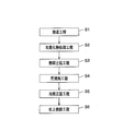
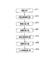
- a method for producing a conductive aluminum plate according to the present invention will be described with reference to FIGS.
- Method for producing conductive aluminum plate As the aluminum material constituting the conductive plate according to the present invention, a non-heat-treatable alloy or a heat-treatable alloy can be used. Therefore, the manufacturing method is “when using a non-heat-treatable alloy” and “ This will be described separately in the case of using a heat-treatable alloy.
- the method for producing a conductive plate material according to the present invention includes a casting step S1, a homogenization heat treatment step S2, and a hot rolling step S3.
- the rough annealing step S4, the cold rolling step S5, and the finish annealing step S6 may be included.
- plate material which concerns on this invention contains washing
- the respective steps will be mainly described.
- the aluminum material having the above-described composition is melted, cast by a known casting method such as a DC casting method, cooled to below the solidus temperature of the aluminum material, and cast to a thickness of about 400 to 600 mm. Make a lump.
- homogenization heat treatment (soaking) is performed at a predetermined temperature before rolling the ingot cast in the casting step S1.
- internal stress is removed, solute elements segregated during casting are homogenized, and intermetallic compounds precipitated during and after casting cooling can be dissolved.
- the soaking process in the homogenization heat treatment step S2 is soaked twice, the first heat treatment temperature (ingot temperature) is 500 to 600 ° C., and the treatment time is 1 to 24 hours, the second time.
- the heat treatment temperature (ingot temperature) may be 350 to 500 ° C., and the treatment time may be 1 to 12 hours.
- the soaking process in the homogenizing heat treatment step S2 is soaked once, the heat treatment temperature (ingot temperature) is 500 to 600 ° C., and the treatment time is 1 to 24 hours. That's fine. Further, when an Al—Mn-based aluminum alloy is used, it may be soaked twice as in the case where pure aluminum is used.
- the homogenization heat treatment step S2 is not more than the hot rolling start temperature once after the homogenization heat treatment even in the “one-time soaking” in which the hot rolling is performed without cooling after the homogenization heat treatment ( For example, it is cooled to normal temperature), and after chamfering, it is reheated and hot-rolled to perform “twice soaking”, after homogenization heat treatment, cooled to the hot rolling start temperature, “Two-stage soaking” in which hot rolling is performed may be used.
- the homogenized ingot is hot rolled.
- the rolling start temperature in the hot rolling step S3 may be 350 to 500 ° C.
- the rolling end temperature may be 250 to 350 ° C.
- the rolling start temperature in the hot rolling step S3 may be 350 to 580 ° C.
- the rolling end temperature may be 250 to 350 ° C.
- it can be set as the hot rolled sheet (hot coil) of desired plate
- a ten-point average roughness of the surface of the conductive plate material is obtained by using a hot rolling roll having a small ten-point average roughness. Can be reduced.
- the contact resistance of the conductive plate material it is preferable to perform rolling by controlling the thickness of the coating formed on the rolled work roll during hot rolling with a brush roll.
- a coating oxide film
- this coating is too thick, the plate surface of the conductive plate will not be in the desired state.
- the thickness of this coating is reduced, the contact resistance of the conductive plate can be kept low even if heat treatment is performed after the hot rolling step. Therefore, it is preferable to perform rolling while controlling the thickness of the coating formed on the rolling work roll during hot rolling using a brush roll.
- the thickness of the coating is preferably 1 to 2 ⁇ m in order to prevent seizure and to make the plate surface of the conductive plate material in a good state.
- a rolling roll having a coating thickness of 1 to 2 ⁇ m By rolling with a rolling roll having a coating thickness of 1 to 2 ⁇ m, the contact resistance of the conductive plate can be easily lowered.
- the control method of a brush roll or coating thickness is not specifically limited.
- the coating thickness can be controlled by rubbing the coating at a predetermined pressure with a brush of a brush roll.
- the brush used for the roll is made of nylon or PBT containing alumina in abrasive grains.
- the thickness of the coating adhered to the rolled work roll during hot rolling can be measured in the following direction. Specifically, first, of the coating adhering to the surface of the rolled work roll, the 10 cm ⁇ 10 cm area coating on the roll surface is dissolved with caustic soda having a concentration of 25 W / V%, and the total amount of the liquid is recovered. Then, the solution is quantified, the aluminum concentration is measured by ICP emission analysis, and the amount of aluminum contained in the collected solution is obtained. Furthermore, assuming that all the melted coatings are alumina and that all the obtained aluminum content constitutes alumina, the film thickness is calculated from the density of alumina (3.95 g / cm 3 ).
- the rolled plate is annealed at a predetermined temperature before cold rolling.
- the heat treatment temperature in the rough annealing step S4 may be 300 to 400 ° C., and the treatment time may be 1 to 12 hours.
- the rolled plate after the rough annealing step S4 is rolled at a recrystallization temperature or lower (for example, normal temperature).
- the ten-point average roughness of the surface of the conductive plate can be reduced by using a cold rolling roll having a small ten-point average roughness.
- the rolling rate in the cold rolling step S5 may be 50 to 95%.
- the rolled sheet after the cold rolling step S5 is annealed.
- the heat treatment temperature in the finish annealing step S6 may be 200 to 400 ° C., and the treatment time may be 1 to 12 hours.
- the cleaning step SW (not shown), the surface of the plate is cleaned in order to remove an oxide film or deposits formed on the surface of the plate.
- the cleaning in the cleaning step SW is not particularly limited as long as it is a method capable of removing oxide films, deposits, etc.
- cleaning with an aqueous alkali solution such as caustic soda (for example, caustic soda concentration: 5 mass%, temperature: 50 ° C., time) : 60 s) followed by a desmutting treatment with nitric acid (for example, nitric acid: 5 mass%, temperature: normal temperature, time: 60 s).
- the cleaning step SW may be provided between the cold rolling step S5 and the finish annealing step S6 or after the finish annealing step S6.
- the method for producing a conductive plate material according to the present invention includes a casting step S11, a homogenization heat treatment step S12, a hot rolling step S13, and a solution heat treatment step. And a cold rolling process SR (SR1, SR2) is included between the hot rolling process S13 and the solution heat treatment process S14 and at least one after the solution heat treatment process S14.
- the manufacturing method of the electrically conductive board material which concerns on this invention may further include artificial aging treatment process S15.
- plate material which concerns on this invention contains washing
- cleaning process SW not shown
- the aluminum material having the above composition is melted, cast by a known casting method such as a DC casting method, cooled to below the solidus temperature of the aluminum material, and cast to a thickness of about 400 to 600 mm. Make a lump.
- a homogenization heat treatment (soaking) is performed at a predetermined temperature before rolling the ingot cast in the casting step S11.
- the ingot By subjecting the ingot to homogenization heat treatment, internal stress is removed, solute elements segregated during casting are homogenized, and intermetallic compounds precipitated during and after casting cooling can be dissolved.
- the soaking in the homogenizing heat treatment step S12 is soaking twice, the first heat treatment temperature (ingot temperature) is 500 to 600 ° C., and the treatment time is 1
- the second heat treatment temperature (ingot temperature) may be 350 to 500 ° C., and the treatment time may be 1 to 12 h.
- the homogenization heat treatment step S12 is performed at a temperature equal to or lower than the hot rolling start temperature once after the homogenization heat treatment even in the “one-time soaking” in which the hot rolling is performed without cooling after the homogenization heat treatment ( For example, it is cooled to normal temperature), and after chamfering, it is reheated and hot-rolled to perform “twice soaking”, after homogenization heat treatment, cooled to the hot rolling start temperature, “Two-stage soaking” in which hot rolling is performed may be used.
- the hot rolling step S13 the homogenized ingot is hot rolled.
- the rolling start temperature in the hot rolling step S13 may be 350 to 500 ° C.
- the rolling end temperature may be 250 to 350 ° C.
- it can be set as the hot rolled sheet (hot coil) of desired plate
- the thickness of the coating formed on the rolled work roll during hot rolling is brushed in the same manner as in the above-mentioned “manufacturing method using a non-heat-treatable alloy”. It is preferable to roll by controlling with a roll.
- the cold rolling process SR (SR1, SR2) is performed twice in the order of the hot rolling process S13 ⁇ the cold rolling process SR1 ⁇ the solution heat treatment process S14 ⁇ the cold rolling process SR2 ⁇ .
- it may be performed once in the order of hot rolling step S13 ⁇ cold rolling step SR1 ⁇ solution heat treatment step S14 ⁇ or hot rolling step S13 ⁇ solution heat treatment step S14 ⁇ cold rolling step SR2.
- cold rolling process SR (SR1, SR2), it rolls below the recrystallization temperature (for example, normal temperature) to the rolled sheet after hot rolling process S13 or solution heat treatment process S14.
- the total cold working rate in the cold rolling step SR may be 0 to 80%.
- a total cold work rate of 0% indicates that hot rolling is performed.
- the ten-point average roughness of the surface of the conductive plate can be reduced by using a cold rolling roll having a small ten-point average roughness.
- total cold work rate (%) (sheet thickness after the hot rolling step S13 ⁇ The plate thickness after the artificial aging treatment step S15) / the plate thickness after the hot rolling step S13 ⁇ 100 ”.
- “plate thickness before artificial aging treatment step S15” may be used as “plate thickness after artificial aging treatment step S15”.
- the solution heat treatment step S14 a solution heat treatment is performed on the rolled plate manufactured in the hot rolling step S13 or the rolled plate manufactured in the cold rolling step SR1.
- the heat treatment temperature in the solution heat treatment step S14 may be 500 to 570 ° C.
- the heat treatment temperature is less than 500 ° C., undissolved Si or Mg remains, so that an appropriate precipitate distribution cannot be obtained after the solution heat treatment and the artificial aging treatment, and a desired yield strength cannot be obtained.
- it exceeds 570 ° C. local melting (burning) occurs on the plate surface. More preferably, it is 520 to 550 ° C.
- the holding time at the heat treatment temperature in the solution heat treatment step S14 may be within 100 seconds (or 0 seconds may be used). This is because when the time exceeds 100 seconds, the effect is saturated and the productivity is lowered. In addition, holding time 0 second shows the case where it cools immediately after the temperature of a rolled sheet reaches solution temperature.
- the rate of temperature increase from 200 ° C. to the heat treatment temperature is preferably 5 ° C./s or more when an Al—Mg—Si alloy is used, and from the heat treatment temperature to 200 ° C.
- the temperature lowering rate is preferably 10 ° C./s or more.
- the rolling process can take various forms other than the above, and for example, a configuration in which the hot rolling process or the rough annealing process is not performed can be employed.
- the artificial aging treatment step S15 the artificial aging treatment is performed on the rolled plate subjected to the solution heat treatment in the solution heat treatment step S14 or the rolled plate subjected to the cold rolling in the cold rolling step SR2.
- the heat treatment temperature in the artificial aging treatment step S15 may be 150 to 250 ° C.
- the heat treatment time may be 1 to 30 hours (h).
- the heat treatment temperature and treatment time in the homogenization heat treatment step S12, solution heat treatment step S14, and artificial aging treatment step S15 are set to the upper limit values or less, and the thickness of the coating of the rolled work roll during hot rolling is adjusted. As a result, the oxide film formed on the surface of the plate can be made thin and the contact resistance can be controlled low.
- the following cleaning step SW (not shown) Is preferably provided.
- the cleaning step SW (not shown), the surface of the plate is cleaned in order to remove an oxide film or deposits formed on the surface of the plate.
- the cleaning in the cleaning step SW is not particularly limited as long as it is a method capable of removing oxide films, deposits, etc.
- cleaning with an aqueous alkali solution such as caustic soda (for example, caustic soda concentration: 5 mass%, temperature: 50 ° C., time) : 60 s) followed by a desmutting treatment with nitric acid (for example, nitric acid concentration: 5 mass%, temperature: normal temperature, time: 60 s).
- the cleaning step SW is provided between the cold rolling step SR2 (solution heat treatment S14 if the cold rolling step SR2 is not performed) and the artificial aging treatment step S15, or after the artificial aging treatment step S15. That's fine.
- the method for producing a conductive plate according to the present invention is as described above. However, in carrying out the present invention, other processes are performed between or before and after each process within a range that does not adversely affect each process. May be included. For example, after the finish annealing step S6 and the artificial aging treatment step S15, a cutting step for cutting the plate material into a predetermined size and a processing step for processing into a predetermined shape (bending, punching, etc.) may be included. . Moreover, you may include a cutting process and a process process before artificial aging treatment process S15.
- the conductive aluminum plate material according to the present invention will be specifically described by comparing an example satisfying the requirements of the present invention with a comparative example not satisfying the requirements of the present invention.
- a case where a non-heat treatment type alloy is used as the aluminum material will be described.
- Aluminum materials (alloys A to D) having the compositions shown in Table 1 were melted, ingots were produced by semi-continuous casting, and face machining was performed. This ingot is subjected to homogenization heat treatment (temperature: 600 ° C., time: 4 h), and then hot rolled at a rolling rate of 99% (start temperature: 400 ° C., end temperature: 300 ° C., final plate thickness: 8 mm). To give a hot rolled sheet.
- the thickness of the hot rolling roll coating was controlled in the range of 1 to 2 ⁇ m.
- the thickness of the hot rolling roll coating was controlled to about 4 ⁇ m.
- the measuring method of the coating thickness of a hot rolling roll was performed as mentioned above.
- Specimens 1 to 4, 6, and 7 were cleaned at the indicated time after finish annealing.
- This cleaning operation involves cleaning with an alkaline aqueous solution such as caustic soda (caustic soda concentration: 5 mass%, temperature: 50 ° C., time: 0 (no cleaning) to 60 s), and then desmutting with nitric acid (nitric acid concentration: 5 mass%).
- nitric acid concentration: 5 mass%) nitric acid concentration: 5 mass%.
- Temperature normal temperature
- time 0 (no washing) to 60 s).
- the value of the contact resistance of the test material was changed by adjusting the coating thickness of the hot rolling roll, the presence or absence of cleaning, the processing time of cleaning, and the like.
- the 10-point average roughness of the surface of a test material was changed by using the thing from which the surface 10-point average roughness differs.
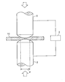
- the contact resistance was determined according to the method described in DVS 2929 of the German Welding Association (DVS) standard. Specifically, as shown in FIG. 3, the test material 10 is sandwiched between a pair of copper electrodes 2 and 2 (tip R: 300 mm, diameter d of the contact portion with the test material 10: 5.5 mm), A load of 7.5 kN was applied. Then, by using a micro ohm meter MRP29 (ohm meter 3 in FIG.
- DVS 2929 German Welding Association
- the conductivity was measured by an eddy current conductivity measuring device [model “Sigma Test D2.068”] manufactured by Nippon Ferster Co., Ltd. In addition, the measurement of the conductivity was performed at any five locations on the surface of the test material with a space of 100 mm or more between each other.
- the electrical conductivity in the present invention is obtained by averaging the measured electrical conductivities. When the value of this conductivity was 50% IACS or more, it was evaluated that the conductive performance as a conductive aluminum plate (electrical connection component) could be secured.
- an aluminum ribbon 20 (width 2 mm, thickness 0.15 mm) manufactured by Tanaka Denshi Kogyo Co., Ltd. is applied to the surface of the test material 10 using fully automatic ribbon bonding (3600R type) manufactured by Orthodyne. Ultrasonic welding. The welding conditions were a frequency of 80 kHz and a load of 2000 g. Moreover, the area of the junction part 30 was 1 mm ⁇ 2 > (1 * 1 mm). The weldability was evaluated by welding with a predetermined ultrasonic oscillation output (Bond Power), and then peeling off the aluminum ribbon 20 by applying force upward with tweezers while fixing the specimen 10 so as not to move. .
- Bond Power ultrasonic oscillation output
- the case where the joining portion 30 of the aluminum ribbon 20 remains on the surface of the test material 10 without breaking the interface between the test material 10 and the aluminum ribbon 20, and the aluminum ribbon 20 is broken, is excellent.
- Judged to be welded was performed while changing the output of the ultrasonic oscillation (Bond Power), and the minimum output at which the above-described well-welded state was obtained was obtained.
- the minimum output value was 80 or less, it was evaluated that weldability as a conductive aluminum plate (electrical connection component) could be secured.
- Tables 1 and 2 Detailed components of the aluminum material and material properties (test results) are shown in Tables 1 and 2. In Tables 1 and 2, numerical values that do not satisfy the configuration of the present invention are underlined.
- the specimen 7 Since the surface of the cold-rolling roll was rough, the specimen 7 had a ten-point average roughness of more than 4.0 ⁇ m, and the weldability was not excellent.
- the test material 8 had a result that the contact resistance exceeded 10 ⁇ and the weldability was not excellent because the finish annealing conditions were inappropriate and the cleaning was not performed.
- the test materials 9 and 10 were not hot because the coating thickness of the hot rolling roll was thick and the cleaning was not performed, so that the contact resistance exceeded 10 ⁇ and the weldability was not excellent.
- Aluminum materials (alloys E and F) having the composition shown in Table 3 were melted, ingots were produced by semi-continuous casting, and surface treatment was performed. This ingot is subjected to homogenization heat treatment (temperature: 550 ° C., time: 4 h), and then hot rolled at a rolling rate of 99% (starting temperature: 400 ° C., finishing temperature: 300 ° C., finishing plate thickness: 2. 2 mm) to obtain a hot rolled sheet. Thereafter, solution heat treatment (plate thickness before treatment: 2.2 mm, temperature: 550 ° C., time: 0 s) was performed.
- the coating thickness of the hot rolling roll was controlled within the range of 1 to 2 ⁇ m.
- the thickness of the hot rolling roll coating was controlled to about 4 ⁇ m.
- the measuring method of the coating thickness of a hot rolling roll was performed as mentioned above.
- the specimens 11 to 13 and 15 were washed at the indicated time after cold rolling and before artificial aging treatment.
- This cleaning operation involves cleaning with an alkaline aqueous solution such as caustic soda (caustic soda concentration: 5 mass%, temperature: 50 ° C., time: 0 (no cleaning) to 60 s), and then desmutting with nitric acid (nitric acid concentration: 5 mass%).
- nitric acid concentration: 5 mass%) Temperature: normal temperature, time: 0 (no washing) to 60 s).
- the value of the contact resistance of the test material was changed by adjusting the coating thickness of the hot rolling roll, the presence or absence of cleaning, the processing time of cleaning, and the like.
- the 10-point average roughness of the surface of a test material was changed by using the thing from which the surface 10-point average roughness differs.
- Tables 3 and 4 show detailed aluminum material components and material characteristics (test results). In Tables 3 and 4, those not satisfying the configuration of the present invention are indicated by underlining the numerical values.
- the test material 15 Since the surface of the cold-rolling roll of the test material 15 was rough, the ten-point average roughness exceeded 4.0 ⁇ m, resulting in poor weldability.
- the test material 16 was inferior in weldability because the contact resistance exceeded 10 ⁇ because the solution heat treatment conditions were inappropriate and cleaning was not performed.
- the test material 17 had a result that the contact resistance exceeded 10 ⁇ and the weldability was not excellent because the coating thickness of the hot rolling roll was thick and the cleaning was not performed.
- the conductive aluminum plate material of the present invention is useful as a connection member between electrical devices in each hot water electric transport device.
Landscapes
- Chemical & Material Sciences (AREA)
- Engineering & Computer Science (AREA)
- Materials Engineering (AREA)
- Mechanical Engineering (AREA)
- Metallurgy (AREA)
- Organic Chemistry (AREA)
- Conductive Materials (AREA)
- Non-Insulated Conductors (AREA)
Abstract
本発明に係る導電用アルミニウム板材は、アルミニウム又はアルミニウム合金からなり、板表面の十点平均粗さが4.0μm以下であるとともに、接触抵抗が10μΩ以下である。
Description
本発明は、導電用アルミニウム板材に関するものである。
電気自動車を始めとする電気を動力源とした各種電動輸送機器(ハイブリッド自動車、燃料電池自動車、電気機関車等)には、電池群、インバータ、モータ等の各種の電気機器が搭載されている。そして、これらの電気機器間または電気機器内部の部品間を電気的に接続するにあたり、板状の電気接続部品が使用されている。
そして、現在まで、板状の電気接続部品に用いられる導電用板材に関し、銅を主体とした素材について検討されてきた。
そして、現在まで、板状の電気接続部品に用いられる導電用板材に関し、銅を主体とした素材について検討されてきた。
しかしながら、近年、自動車の燃費性能を向上させるために、自動車の軽量化、そして、自動車に搭載される電気機器の軽量化が求められている。
このような事情を勘案し、銅よりも軽量であるアルミニウム又はアルミニウム合金からなる導電用アルミニウム板材が提案されている。
このような事情を勘案し、銅よりも軽量であるアルミニウム又はアルミニウム合金からなる導電用アルミニウム板材が提案されている。
例えば、特許文献1には、Si0.3~0.8wt%、Mg0.35~1.0wt%、Fe0.1~0.6wt%、Cu0.12~0.5wt%を含有し、さらにMn0.1~0.3wt%、Zr0.1~0.3wt%の1種又は2種を含有し、残部がAlと不可避的不純物からなるAl合金であり、導電率が55%IACS以上で、且つその調質がT6材であることを特徴とする、自動車に搭載するAl合金製の給電用導電体が記載されている。
導電用板材は、ボンディングワイヤ等の部材との接合が必要となる場合があり、当該場合は、導電用板材とボンディングワイヤの端部とを加圧しながら超音波を印加する超音波溶接といった方法が採用されている。
ここで、導電用板材とボンディングワイヤとを強固に溶接するには、加圧する圧力および印加する超音波のパワーを大きくすればよいが、これらを大きくすると導電用板材やボンディングワイヤが変形するといった不具合が生じてしまう。つまり、超音波溶接の溶接条件を制御するだけでは、溶接性の向上には限界がある。したがって、導電用板材自体を、溶接性の優れたものとする必要がある。
ここで、導電用板材とボンディングワイヤとを強固に溶接するには、加圧する圧力および印加する超音波のパワーを大きくすればよいが、これらを大きくすると導電用板材やボンディングワイヤが変形するといった不具合が生じてしまう。つまり、超音波溶接の溶接条件を制御するだけでは、溶接性の向上には限界がある。したがって、導電用板材自体を、溶接性の優れたものとする必要がある。
しかしながら、導電用板材の中でも、特許文献1のようにアルミニウム又はアルミニウム合金を用いた導電用板材については、溶接性に関して検討すらされていない状況であって、特に、好ましい表面性状については全く不明であった。
そこで、本発明は、溶接性に優れる導電用アルミニウム板材を提供することを課題とする。
すなわち、本発明に係る導電用アルミニウム板材は、アルミニウム又はアルミニウム合金からなり、板表面の十点平均粗さが4.0μm以下であるとともに、接触抵抗が10μΩ以下である。
この導電用アルミニウム板材によれば、板表面の十点平均粗さが所定値以下であることから、ボンディングワイヤ等の部材の溶接後の接合界面において、ボイドの発生が抑制され、接合強度の低下を防止することができる。また、接触抵抗が所定値以下であることから、導電用アルミニウム板材とボンディングワイヤ等の部材とを溶接する際、板表面に形成される酸化皮膜や付着物等が溶接を阻害する程度を制限することができる。
その結果、この導電用アルミニウム板材は、優れた溶接性を発揮することができる。
その結果、この導電用アルミニウム板材は、優れた溶接性を発揮することができる。
本発明に係る導電用アルミニウム板材は、前記アルミニウム又はアルミニウム合金が非熱処理型合金であってもよい。
また、本発明に係る導電用アルミニウム板材は、前記アルミニウム又はアルミニウム合金が熱処理型合金であってもよい。
また、本発明に係る導電用アルミニウム板材は、前記アルミニウム又はアルミニウム合金が熱処理型合金であってもよい。
本発明に係る導電用アルミニウム板材は、前記アルミニウム又はアルミニウム合金が1000系のアルミニウムであってもよい。
また、本発明に係る導電用アルミニウム板材は、前記アルミニウム又はアルミニウム合金が3000系のアルミニウム合金であってもよい。
また、本発明に係る導電用アルミニウム板材は、前記アルミニウム又はアルミニウム合金が6000系のアルミニウム合金であってもよい。
また、本発明に係る導電用アルミニウム板材は、前記アルミニウム又はアルミニウム合金が3000系のアルミニウム合金であってもよい。
また、本発明に係る導電用アルミニウム板材は、前記アルミニウム又はアルミニウム合金が6000系のアルミニウム合金であってもよい。
本発明に係る導電用アルミニウム板材は、前記アルミニウム又はアルミニウム合金が、Si:0.25質量%以下、Fe:0.80質量%以下、Cu:0.20質量%以下、Mn:0.05質量%以下、Mg:0.05質量%以下、Zn:0.10質量%以下、Ti:0.05質量%以下、V:0.05質量%以下、Al:99.00質量%以上、残部:不可避的不純物、であってもよい。
また、本発明に係る導電用アルミニウム板材は、前記アルミニウム又はアルミニウム合金が、Si:0.6質量%以下、Fe:0.8質量%以下、Cu:0.30質量%以下、Mn:0.3~1.5質量%、Mg:1.3質量%以下、Zn:0.40質量%以下、Ti:0.20質量%以下、残部:Alおよび不可避的不純物、であってもよい。
また、本発明に係る導電用アルミニウム板材は、前記アルミニウム又はアルミニウム合金が、Si:0.30~1.30質量%、Fe:0.50質量%以下、Cu:0.10質量%以下、Mn:1.0質量%以下、Mg:0.35~1.20質量%、Cr:0.25質量%以下、Zn:0.20質量%以下、Ti:0.10質量%以下、B:0.06質量%以下、残部:Alおよび不可避的不純物、であってもよい。
また、本発明に係る導電用アルミニウム板材は、前記アルミニウム又はアルミニウム合金が、Si:0.6質量%以下、Fe:0.8質量%以下、Cu:0.30質量%以下、Mn:0.3~1.5質量%、Mg:1.3質量%以下、Zn:0.40質量%以下、Ti:0.20質量%以下、残部:Alおよび不可避的不純物、であってもよい。
また、本発明に係る導電用アルミニウム板材は、前記アルミニウム又はアルミニウム合金が、Si:0.30~1.30質量%、Fe:0.50質量%以下、Cu:0.10質量%以下、Mn:1.0質量%以下、Mg:0.35~1.20質量%、Cr:0.25質量%以下、Zn:0.20質量%以下、Ti:0.10質量%以下、B:0.06質量%以下、残部:Alおよび不可避的不純物、であってもよい。
本発明に係る導電用アルミニウム板材は、十点平均粗さが所定値以下であるとともに、接触抵抗が所定値以下であることから、優れた溶接性を発揮することができる。
以下、本発明に係る導電用アルミニウム板材を実施するための形態について、詳細に説明する。
[導電用アルミニウム板材]
本発明に係る導電用アルミニウム板材(以下、適宜「導電用板材」という)は、アルミニウム又はアルミニウム合金(以下、適宜「アルミニウム材」という)からなり、板表面の十点平均粗さが所定値以下であるとともに、接触抵抗が所定値以下である。
以下、導電用板材を構成するアルミニウム材の種類、十点平均粗さ(Rzjis)、接触抵抗について、規定した理由を説明する。
本発明に係る導電用アルミニウム板材(以下、適宜「導電用板材」という)は、アルミニウム又はアルミニウム合金(以下、適宜「アルミニウム材」という)からなり、板表面の十点平均粗さが所定値以下であるとともに、接触抵抗が所定値以下である。
以下、導電用板材を構成するアルミニウム材の種類、十点平均粗さ(Rzjis)、接触抵抗について、規定した理由を説明する。
≪アルミニウム又はアルミニウム合金≫
本発明に係る導電用板材を構成するアルミニウム材としては、非熱処理型合金を用いることも、熱処理型合金を用いることも可能である。
本発明に係る導電用板材を構成するアルミニウム材としては、非熱処理型合金を用いることも、熱処理型合金を用いることも可能である。
<非熱処理型合金>
非熱処理型合金とは、熱処理ではなく加工硬化により所望の強度を得る合金である。
そして、非熱処理型合金としては、合金番号が1000番台の1000系のアルミニウム(純アルミニウム)、合金番号が3000番台の3000系のアルミニウム合金(Al-Mn系合金)、合金番号が5000番台の5000系のアルミニウム合金(Al-Mg系合金)を用いることができる。
なお、本明細書に示す合金番号は、JIS H 4000:2014に基づくものである。
非熱処理型合金とは、熱処理ではなく加工硬化により所望の強度を得る合金である。
そして、非熱処理型合金としては、合金番号が1000番台の1000系のアルミニウム(純アルミニウム)、合金番号が3000番台の3000系のアルミニウム合金(Al-Mn系合金)、合金番号が5000番台の5000系のアルミニウム合金(Al-Mg系合金)を用いることができる。
なお、本明細書に示す合金番号は、JIS H 4000:2014に基づくものである。
(1000系のアルミニウム)
1000系のアルミニウムは、Alの含有量が99.00質量%以上の純アルミニウムであって、加工性、耐食性、溶接性などに優れるが、強度は低い。
導電用板材を構成するアルミニウム材として、1000系のアルミニウムを用いる場合は、例えば、Si:0.25質量%以下、Fe:0.80質量%以下、Cu:0.20質量%以下、Mn:0.05質量%以下、Mg:0.05質量%以下、Zn:0.10質量%以下、Ti:0.05質量%以下、V:0.05質量%以下、Al:99.00質量%以上、残部:不可避的不純物(例えば、前記元素以外の元素の各含有量が0.05質量%以下)、というものを用いることができる。
1000系のアルミニウムは、Alの含有量が99.00質量%以上の純アルミニウムであって、加工性、耐食性、溶接性などに優れるが、強度は低い。
導電用板材を構成するアルミニウム材として、1000系のアルミニウムを用いる場合は、例えば、Si:0.25質量%以下、Fe:0.80質量%以下、Cu:0.20質量%以下、Mn:0.05質量%以下、Mg:0.05質量%以下、Zn:0.10質量%以下、Ti:0.05質量%以下、V:0.05質量%以下、Al:99.00質量%以上、残部:不可避的不純物(例えば、前記元素以外の元素の各含有量が0.05質量%以下)、というものを用いることができる。
そして、導電用板材を構成するアルミニウム材として、1000系のアルミニウムを用いる場合は、例えば、合金番号1050、1100、1200のものを用いることができる。
詳細には、合金番号1050のアルミニウムとは、Si:0.25質量%以下、Fe:0.40質量%以下、Cu:0.05質量%以下、Mn:0.05質量%以下、Mg:0.05質量%以下、Zn:0.05質量%以下、Ti:0.03質量%以下、V:0.05質量%以下、Al:99.50質量%以上、残部:不可避的不純物(前記元素以外の元素の各含有量が0.03質量%以下)を満たすものである。
また、合金番号1100のアルミニウムとは、Si+Fe:0.95質量%以下、Cu:0.05~0.20質量%、Mn:0.05質量%以下、Zn:0.10質量%以下、Al:99.00質量%以上、残部:不可避的不純物(前記元素以外の元素の各含有量が0.05質量%以下、かつ、前記元素以外の元素の合計の含有量が0.15質量%以下)を満たすものである。
また、合金番号1200のアルミニウムとは、Si+Fe:1.00質量%以下、Cu:0.05質量%以下、Mn:0.05質量%以下、Zn:0.10質量%以下、Ti:0.05質量%以下、Al:99.00質量%以上、残部:不可避的不純物(前記元素以外の元素の各含有量が0.05質量%以下、かつ、前記元素以外の元素の合計の含有量が0.15質量%以下)を満たすものである。
詳細には、合金番号1050のアルミニウムとは、Si:0.25質量%以下、Fe:0.40質量%以下、Cu:0.05質量%以下、Mn:0.05質量%以下、Mg:0.05質量%以下、Zn:0.05質量%以下、Ti:0.03質量%以下、V:0.05質量%以下、Al:99.50質量%以上、残部:不可避的不純物(前記元素以外の元素の各含有量が0.03質量%以下)を満たすものである。
また、合金番号1100のアルミニウムとは、Si+Fe:0.95質量%以下、Cu:0.05~0.20質量%、Mn:0.05質量%以下、Zn:0.10質量%以下、Al:99.00質量%以上、残部:不可避的不純物(前記元素以外の元素の各含有量が0.05質量%以下、かつ、前記元素以外の元素の合計の含有量が0.15質量%以下)を満たすものである。
また、合金番号1200のアルミニウムとは、Si+Fe:1.00質量%以下、Cu:0.05質量%以下、Mn:0.05質量%以下、Zn:0.10質量%以下、Ti:0.05質量%以下、Al:99.00質量%以上、残部:不可避的不純物(前記元素以外の元素の各含有量が0.05質量%以下、かつ、前記元素以外の元素の合計の含有量が0.15質量%以下)を満たすものである。
(3000系のアルミニウム合金)
3000系のアルミニウム合金は、Mnを含有したAl-Mn系合金であって、Mnの添加によって、純アルミニウムの加工性、耐食性が低下することなく、強度が少し増加している。
導電用板材を構成するアルミニウム材として、3000系のアルミニウム合金を用いる場合は、例えば、Si:0.6質量%以下、Fe:0.8質量%以下、Cu:0.30質量%以下、Mn:0.3~1.5質量%、Mg:1.3質量%以下、Zn:0.40質量%以下、Ti:0.20質量%以下、残部:Alおよび不可避的不純物(例えば、前記元素以外の元素の各含有量が0.05質量%以下、かつ、前記元素以外の元素の合計の含有量が0.15質量%以下)、というものを用いることができる。
3000系のアルミニウム合金は、Mnを含有したAl-Mn系合金であって、Mnの添加によって、純アルミニウムの加工性、耐食性が低下することなく、強度が少し増加している。
導電用板材を構成するアルミニウム材として、3000系のアルミニウム合金を用いる場合は、例えば、Si:0.6質量%以下、Fe:0.8質量%以下、Cu:0.30質量%以下、Mn:0.3~1.5質量%、Mg:1.3質量%以下、Zn:0.40質量%以下、Ti:0.20質量%以下、残部:Alおよび不可避的不純物(例えば、前記元素以外の元素の各含有量が0.05質量%以下、かつ、前記元素以外の元素の合計の含有量が0.15質量%以下)、というものを用いることができる。
そして、導電用板材を構成するアルミニウム材として、3000系のアルミニウムを用いる場合は、例えば、合金番号3003のものを用いることができる。
詳細には、合金番号3003のアルミニウム合金とは、Si:0.6質量%以下、Fe:0.7質量%以下、Cu:0.05~0.20質量%、Mn:1.0~1.5質量%、Zn:0.10質量%以下、残部:Alおよび不可避的不純物(前記元素以外の元素の各含有量が0.05質量%以下、かつ、前記元素以外の元素の合計の含有量が0.15質量%以下)を満たすものである。
詳細には、合金番号3003のアルミニウム合金とは、Si:0.6質量%以下、Fe:0.7質量%以下、Cu:0.05~0.20質量%、Mn:1.0~1.5質量%、Zn:0.10質量%以下、残部:Alおよび不可避的不純物(前記元素以外の元素の各含有量が0.05質量%以下、かつ、前記元素以外の元素の合計の含有量が0.15質量%以下)を満たすものである。
(5000系のアルミニウム合金)
5000系のアルミニウム合金は、Mgを含有したAl-Mg系合金であって、Mg含有量の比較的少ないものは装飾用材や器物用材に使用され、比較的多いものは構造材に使用される。
導電用板材を構成するアルミニウム材として、5000系のアルミニウム合金を用いる場合は、例えば、Si:0.40質量%以下、Fe:0.7質量%以下、Cu:0.20質量%以下、Mn:1.0質量%以下、Mg:0.50~5.6質量%、Cr:0.35質量%以下、Zn:0.25質量%以下、残部:Alおよび不可避的不純物、というものを用いることができる。
5000系のアルミニウム合金は、Mgを含有したAl-Mg系合金であって、Mg含有量の比較的少ないものは装飾用材や器物用材に使用され、比較的多いものは構造材に使用される。
導電用板材を構成するアルミニウム材として、5000系のアルミニウム合金を用いる場合は、例えば、Si:0.40質量%以下、Fe:0.7質量%以下、Cu:0.20質量%以下、Mn:1.0質量%以下、Mg:0.50~5.6質量%、Cr:0.35質量%以下、Zn:0.25質量%以下、残部:Alおよび不可避的不純物、というものを用いることができる。
これらの中では、導電性や加工性(曲げ性)等にも優れることから、1000系アルミニウム及び3000系アルミニウム合金が好ましい。
<熱処理型合金>
熱処理型合金とは、熱処理により所望の強度を得る合金である。
そして、熱処理型合金としては、JIS H 4000:2014に記載されている合金番号が2000番台の2000系アルミニウム合金(Al-Cu系合金)、合金番号が6000番台の6000系のアルミニウム合金(Al-Mg-Si系合金)、合金番号が7000番台の7000系のアルミニウム合金(Al-Zn-Mg系合金)を用いることができる。
熱処理型合金とは、熱処理により所望の強度を得る合金である。
そして、熱処理型合金としては、JIS H 4000:2014に記載されている合金番号が2000番台の2000系アルミニウム合金(Al-Cu系合金)、合金番号が6000番台の6000系のアルミニウム合金(Al-Mg-Si系合金)、合金番号が7000番台の7000系のアルミニウム合金(Al-Zn-Mg系合金)を用いることができる。
(2000系のアルミニウム合金)
2000系のアルミニウム合金は、Cuを含有したAl-Cu系合金であって、強度に非常に優れるが、耐食性に劣る。
導電用板材を構成するアルミニウム材として、2000系のアルミニウム合金を用いる場合は、例えば、Si:1.3質量%以下、Fe:1.5質量%以下、Cu:1.5~6.8質量%、Mn:1.2質量%以下、Mg:1.8質量%以下、Cr:0.10質量%以下、Zn:0.50質量%以下、Ti:0.20質量%以下、残部:Alおよび不可避的不純物、というものを用いることができる。
2000系のアルミニウム合金は、Cuを含有したAl-Cu系合金であって、強度に非常に優れるが、耐食性に劣る。
導電用板材を構成するアルミニウム材として、2000系のアルミニウム合金を用いる場合は、例えば、Si:1.3質量%以下、Fe:1.5質量%以下、Cu:1.5~6.8質量%、Mn:1.2質量%以下、Mg:1.8質量%以下、Cr:0.10質量%以下、Zn:0.50質量%以下、Ti:0.20質量%以下、残部:Alおよび不可避的不純物、というものを用いることができる。
(6000系のアルミニウム合金)
6000系のアルミニウム合金は、Mg、Siを含有したAl-Mg-Si系合金であって、強度、耐食性ともに良好なため、アルミニウム材の中でも代表的な構造材として挙げられる。
導電用板材を構成するアルミニウム材として、6000系のアルミニウム合金を用いる場合は、例えば、Si:0.30~1.30質量%、Fe:0.50質量%以下、Cu:0.10質量%以下、Mn:1.0質量%以下、Mg:0.35~1.20質量%、Cr:0.25質量%以下、Zn:0.20質量%以下、Ti:0.10質量%以下、B:0.06質量%以下、残部:Alおよび不可避的不純物(例えば、前記元素以外の元素の各含有量が0.05質量%以下、かつ、前記元素以外の元素の合計の含有量が0.15質量%以下)、というものを用いることができる。
6000系のアルミニウム合金は、Mg、Siを含有したAl-Mg-Si系合金であって、強度、耐食性ともに良好なため、アルミニウム材の中でも代表的な構造材として挙げられる。
導電用板材を構成するアルミニウム材として、6000系のアルミニウム合金を用いる場合は、例えば、Si:0.30~1.30質量%、Fe:0.50質量%以下、Cu:0.10質量%以下、Mn:1.0質量%以下、Mg:0.35~1.20質量%、Cr:0.25質量%以下、Zn:0.20質量%以下、Ti:0.10質量%以下、B:0.06質量%以下、残部:Alおよび不可避的不純物(例えば、前記元素以外の元素の各含有量が0.05質量%以下、かつ、前記元素以外の元素の合計の含有量が0.15質量%以下)、というものを用いることができる。
そして、導電用板材を構成するアルミニウム材として、6000系のアルミニウムを用いる場合は、例えば、合金番号6101、6082のものを用いることができる。
詳細には、合金番号6101のアルミニウム合金とは、Si:0.30~0.7質量%、Fe:0.50質量%以下、Cu:0.10質量%以下、Mn:0.03質量%以下、Mg:0.35~0.8質量%、Cr:0.03質量%以下、Zn:0.10質量%以下、B:0.06質量%以下、残部:Alおよび不可避的不純物(前記元素以外の元素の各含有量が0.03質量%以下、かつ、前記元素以外の元素の合計の含有量が0.10質量%以下)を満たすものである。
また、合金番号6082のアルミニウム合金とは、Si:0.7~1.3質量%、Fe:0.50質量%以下、Cu:0.10質量%以下、Mn:0.40~1.0質量%、Mg:0.6~1.2質量%、Cr:0.25質量%以下、Zn:0.20質量%以下、Ti:0.10質量%以下、残部:Alおよび不可避的不純物(前記元素以外の元素の各含有量が0.05質量%以下、かつ、前記元素以外の元素の合計の含有量が0.15質量%以下)を満たすものである。
詳細には、合金番号6101のアルミニウム合金とは、Si:0.30~0.7質量%、Fe:0.50質量%以下、Cu:0.10質量%以下、Mn:0.03質量%以下、Mg:0.35~0.8質量%、Cr:0.03質量%以下、Zn:0.10質量%以下、B:0.06質量%以下、残部:Alおよび不可避的不純物(前記元素以外の元素の各含有量が0.03質量%以下、かつ、前記元素以外の元素の合計の含有量が0.10質量%以下)を満たすものである。
また、合金番号6082のアルミニウム合金とは、Si:0.7~1.3質量%、Fe:0.50質量%以下、Cu:0.10質量%以下、Mn:0.40~1.0質量%、Mg:0.6~1.2質量%、Cr:0.25質量%以下、Zn:0.20質量%以下、Ti:0.10質量%以下、残部:Alおよび不可避的不純物(前記元素以外の元素の各含有量が0.05質量%以下、かつ、前記元素以外の元素の合計の含有量が0.15質量%以下)を満たすものである。
(7000系のアルミニウム合金)
7000系のアルミニウム合金は、Zn、Mgを含有したAl-Zn-Mg系合金であって、アルミニウム材の中でも最も高い強度を有する。
導電用板材を構成するアルミニウム材として、7000系のアルミニウム合金を用いる場合は、例えば、Si:0.40質量%以下、Fe:0.5質量%以下、Cu:2.6質量%以下、Mn:0.70質量%以下、Mg:3.1質量%以下、Cr:0.35質量%以下、Zn:0.8~7.3質量%、Ti:0.20質量%以下、残部:Alおよび不可避的不純物、というものを用いることができる。
7000系のアルミニウム合金は、Zn、Mgを含有したAl-Zn-Mg系合金であって、アルミニウム材の中でも最も高い強度を有する。
導電用板材を構成するアルミニウム材として、7000系のアルミニウム合金を用いる場合は、例えば、Si:0.40質量%以下、Fe:0.5質量%以下、Cu:2.6質量%以下、Mn:0.70質量%以下、Mg:3.1質量%以下、Cr:0.35質量%以下、Zn:0.8~7.3質量%、Ti:0.20質量%以下、残部:Alおよび不可避的不純物、というものを用いることができる。
これらの中では、導電性や加工性等にも優れることから、6000系アルミニウム合金が好ましい。
≪十点平均粗さ≫
本発明に係る導電用板材は、表面の十点平均粗さ(Rzjis)が、4.0μm以下である。なお、十点平均粗さ(Rzjis)とは、JIS B 0601:2001に規定されている粗さパラメータであり、基準長さにおける最も高い山頂から5番目までの山頂の標高(Yp)の絶対値の平均値と、最も低い谷底から5番目までの谷底の標高(Yv)の絶対値の平均値との和を求めた値である。
本発明に係る導電用板材は、表面の十点平均粗さ(Rzjis)が、4.0μm以下である。なお、十点平均粗さ(Rzjis)とは、JIS B 0601:2001に規定されている粗さパラメータであり、基準長さにおける最も高い山頂から5番目までの山頂の標高(Yp)の絶対値の平均値と、最も低い谷底から5番目までの谷底の標高(Yv)の絶対値の平均値との和を求めた値である。
十点平均粗さが4.0μm以下であると、超音波溶接により導電用板材とボンディングワイヤ等の部材とを溶接する際、表面が十分に滑らかであることにより、溶接後の接合界面においてボイドの発生が抑制され、接合強度が低下しないことから、優れた溶接性を確保することができる。一方、十点平均粗さが4.0μmを超えると、導電用板材とボンディングワイヤ等の部材とを溶接する際、接合界面においてボイドが発生し、接合強度の低下を招き、溶接性を低下させてしまう。
なお、十点平均粗さについては、溶接性の向上という効果をより確実なものとするため、好ましくは3.0μm以下である。また、十点平均粗さについては、小さければ小さいほど好ましい。
なお、十点平均粗さについては、溶接性の向上という効果をより確実なものとするため、好ましくは3.0μm以下である。また、十点平均粗さについては、小さければ小さいほど好ましい。
十点平均粗さ(Rzjis)は、JIS B 0601:2001の規定に準拠して、市販の測定器を用いて測定することができる。そして、十点平均粗さは、導電用板材の表面に酸化皮膜が形成されている場合、当該酸化皮膜の表面の粗さであり、当該酸化皮膜が形成された状態で十点平均粗さを測定すればよい。
なお、導電用板材の十点平均粗さは、冷間圧延を施さない導電用板材(熱間圧延仕上げ)の場合、熱間圧延ロール表面の十点平均粗さが小さいものを用いること等により達成され、冷間圧延を施す導電用板材の場合、冷間圧延ロール表面の十点平均粗さが小さいものを用いること等により達成される。
なお、導電用板材の十点平均粗さは、冷間圧延を施さない導電用板材(熱間圧延仕上げ)の場合、熱間圧延ロール表面の十点平均粗さが小さいものを用いること等により達成され、冷間圧延を施す導電用板材の場合、冷間圧延ロール表面の十点平均粗さが小さいものを用いること等により達成される。
≪接触抵抗≫
本発明に係る導電用板材は、接触抵抗が、10μΩ以下である。
接触抵抗が、10μΩ以下であると、超音波溶接により導電用板材とボンディングワイヤ等の部材とを溶接する際、板表面に形成される酸化皮膜や付着物等が溶接を阻害する程度を制限できるため、優れた溶接性を確保することができる。
一方、接触抵抗が、10μΩを超えると、導電用板材とボンディングワイヤ等の部材とを溶接する際、板表面に形成される酸化皮膜や付着物等が溶接を阻害してしまい、溶接性を低下させてしまう。
なお、接触抵抗については、溶接性の向上という効果をより向上させるため、好ましくは5μΩ以下であり、より好ましくは1μΩ以下である。また、接触抵抗については、下限は特に限定されないものの、例えば0.1μΩ以上であればよい。
本発明に係る導電用板材は、接触抵抗が、10μΩ以下である。
接触抵抗が、10μΩ以下であると、超音波溶接により導電用板材とボンディングワイヤ等の部材とを溶接する際、板表面に形成される酸化皮膜や付着物等が溶接を阻害する程度を制限できるため、優れた溶接性を確保することができる。
一方、接触抵抗が、10μΩを超えると、導電用板材とボンディングワイヤ等の部材とを溶接する際、板表面に形成される酸化皮膜や付着物等が溶接を阻害してしまい、溶接性を低下させてしまう。
なお、接触抵抗については、溶接性の向上という効果をより向上させるため、好ましくは5μΩ以下であり、より好ましくは1μΩ以下である。また、接触抵抗については、下限は特に限定されないものの、例えば0.1μΩ以上であればよい。
接触抵抗については、ドイツ溶接協会(DVS)規格のDVS2929に記載の方法に準拠して測定することができる。そして、測定装置としては、市販のオームメーターを用いればよい。
なお、接触抵抗については、製造時において洗浄工程を行ったり、各熱処理を施す際の熱処理温度および時間を所定値以下としたりすること等により、板表面に形成される酸化皮膜や付着物等を薄く又は少なくすることで、低下させることができる。
なお、接触抵抗については、製造時において洗浄工程を行ったり、各熱処理を施す際の熱処理温度および時間を所定値以下としたりすること等により、板表面に形成される酸化皮膜や付着物等を薄く又は少なくすることで、低下させることができる。
≪その他の特性≫
<導電率>
本発明に係る導電用板材は、非熱処理型合金(特に、純アルミニウム、Al-Mn系合金)を用いる場合、導電率が、50%IACS以上であるのが好ましく、55%IACS以上であることがさらに好ましく、60%IACS以上であることが特に好ましい。
本発明に係る導電用板材は、熱処理型合金(特に、Al-Mg-Si系合金)を用いる場合、導電率が、40.0%IACS以上であるのが好ましく、45.0%IACS以上であるのがより好ましく、47.0%IACS以上であることがさらに好ましく、50.0%IACS以上であることが特に好ましい。
<導電率>
本発明に係る導電用板材は、非熱処理型合金(特に、純アルミニウム、Al-Mn系合金)を用いる場合、導電率が、50%IACS以上であるのが好ましく、55%IACS以上であることがさらに好ましく、60%IACS以上であることが特に好ましい。
本発明に係る導電用板材は、熱処理型合金(特に、Al-Mg-Si系合金)を用いる場合、導電率が、40.0%IACS以上であるのが好ましく、45.0%IACS以上であるのがより好ましく、47.0%IACS以上であることがさらに好ましく、50.0%IACS以上であることが特に好ましい。
導電率が前記の値以上であると、導電用板材としての導電性能を確保することができる。一方、電気抵抗が高い、すなわち導電率が前記の値未満であると、所望の電流を流すために導電用板材の断面積を増加させる必要が生じ、部品重量の増加に繋がってしまう。
なお、導電率については、非熱処理型合金(特に、純アルミニウム、Al-Mn系合金)を用いる場合と、熱処理型合金(特に、Al-Mg-Si系合金)を用いる場合とにおいて、成分組成の相違により、根本的な導電率が異なる。よって、各合金に対してユーザーが要求する導電率のレベルも異なるため、前記のように異なる下限値を示した。
なお、導電率については、非熱処理型合金(特に、純アルミニウム、Al-Mn系合金)を用いる場合と、熱処理型合金(特に、Al-Mg-Si系合金)を用いる場合とにおいて、成分組成の相違により、根本的な導電率が異なる。よって、各合金に対してユーザーが要求する導電率のレベルも異なるため、前記のように異なる下限値を示した。
導電率の調整は、導電用板材のSiの含有量、Mgの含有量を前記の範囲内とするとともに、製造工程における均質化熱処理条件、溶体化熱処理条件、人工時効処理条件を後記する条件で行うことによって達成することができる。
<耐力>
本発明に係る導電用板材は、非熱処理型合金(特に、純アルミニウム、Al-Mn系合金)を用いる場合、耐力(0.2%耐力)が、20MPa以上であることが好ましく、40MPa以上であることがさらに好ましく、50MPa以上であることが特に好ましい。
本発明に係る導電用板材は、熱処理型合金(特に、Al-Mg-Si系合金)を用いる場合、耐力(0.2%耐力)が、130MPa以上であることが好ましく、175MPa以上であることがさらに好ましく、180MPa以上であることが特に好ましい。
本発明に係る導電用板材は、非熱処理型合金(特に、純アルミニウム、Al-Mn系合金)を用いる場合、耐力(0.2%耐力)が、20MPa以上であることが好ましく、40MPa以上であることがさらに好ましく、50MPa以上であることが特に好ましい。
本発明に係る導電用板材は、熱処理型合金(特に、Al-Mg-Si系合金)を用いる場合、耐力(0.2%耐力)が、130MPa以上であることが好ましく、175MPa以上であることがさらに好ましく、180MPa以上であることが特に好ましい。
耐力が前記の値以上であると、導電用板材に要求される耐力を確保することができる。一方、耐力が前記の値未満であると、耐力が低く、導電用板材として好適に用いることができない。
なお、耐力については、非熱処理型合金(特に、純アルミニウム、Al-Mn系合金)を用いる場合と、熱処理型合金(特に、Al-Mg-Si系合金)を用いる場合とにおいて、成分組成の相違により、根本的な耐力が異なる。よって、各合金に対してユーザーが要求する耐力のレベルも異なるため、前記のように異なる下限値を示した。
なお、耐力については、非熱処理型合金(特に、純アルミニウム、Al-Mn系合金)を用いる場合と、熱処理型合金(特に、Al-Mg-Si系合金)を用いる場合とにおいて、成分組成の相違により、根本的な耐力が異なる。よって、各合金に対してユーザーが要求する耐力のレベルも異なるため、前記のように異なる下限値を示した。
耐力の調整は、導電用板材のSiの含有量、Mgの含有量を前記の範囲内とするとともに、製造工程における均質化熱処理条件、溶体化処理条件、人工時効処理条件を後記する条件で行うことによって達成することができる。
≪導電用≫
導電用とは、複数の部材を電気的に接続するためのものという用途を示しており、本発明に係る導電用板材とは、この用途のための板材である。
そして、詳細には、本発明に係る導電用板材は、電気接続部品(特に、板状の材料に対して曲げ加工が施されるような電気接続部品)に用いる板材である。
なお、ここでの電気接続部品とは、具体的には、電気を動力源とした各種電動輸送機器等に搭載されている、電池群、インバータ、モータ等の各種の電気機器間または電気機器内部の部品間を電気的に接続する部品である。また、電気接続部品とは、ボンディングワイヤ等の部材を表面に接合することが要求される部品でもある。
なお、電気接続部品(導電用板材)の板厚については、特に限定されないが、アルミニウム材が銅等と比較して導電率が低いことを考慮し、例えば、1.5mm以上、1.8~5.0mmとすればよい。
導電用とは、複数の部材を電気的に接続するためのものという用途を示しており、本発明に係る導電用板材とは、この用途のための板材である。
そして、詳細には、本発明に係る導電用板材は、電気接続部品(特に、板状の材料に対して曲げ加工が施されるような電気接続部品)に用いる板材である。
なお、ここでの電気接続部品とは、具体的には、電気を動力源とした各種電動輸送機器等に搭載されている、電池群、インバータ、モータ等の各種の電気機器間または電気機器内部の部品間を電気的に接続する部品である。また、電気接続部品とは、ボンディングワイヤ等の部材を表面に接合することが要求される部品でもある。
なお、電気接続部品(導電用板材)の板厚については、特に限定されないが、アルミニウム材が銅等と比較して導電率が低いことを考慮し、例えば、1.5mm以上、1.8~5.0mmとすればよい。
≪導電用アルミニウム板材の調質≫
導電用板材の調質については、特に限定されない。
例えば、導電用板材は、非熱処理型合金を用いる場合、後記する熱間圧延工程S3後の状態のもの(JIS質別記号H112)であってもよいし、後記する仕上焼鈍工程S6後の状態もの(JIS質別記号O、H2n)であってもよいし、後記する仕上焼鈍工程S6を施していないもの(JIS質別記号H1n)であってもよい。
また、導電用板材は、熱処理型合金を用いる場合、後記する人工時効処理工程S15後のもの(JIS質別記号T8)であってもよいし、人工時効処理工程S15を施していないもの(JIS質別記号T4)であってもよい。さらに、溶体化熱処理工程S14後、冷間圧延を行わず人工時効処理S15を行うもの(JIS質別記号T6)であってもよい。
なお、JIS質別記号は、JIS H 0001:1998の記載に基づいている。
導電用板材の調質については、特に限定されない。
例えば、導電用板材は、非熱処理型合金を用いる場合、後記する熱間圧延工程S3後の状態のもの(JIS質別記号H112)であってもよいし、後記する仕上焼鈍工程S6後の状態もの(JIS質別記号O、H2n)であってもよいし、後記する仕上焼鈍工程S6を施していないもの(JIS質別記号H1n)であってもよい。
また、導電用板材は、熱処理型合金を用いる場合、後記する人工時効処理工程S15後のもの(JIS質別記号T8)であってもよいし、人工時効処理工程S15を施していないもの(JIS質別記号T4)であってもよい。さらに、溶体化熱処理工程S14後、冷間圧延を行わず人工時効処理S15を行うもの(JIS質別記号T6)であってもよい。
なお、JIS質別記号は、JIS H 0001:1998の記載に基づいている。
次に、本発明に係る導電用アルミニウム板材の製造方法について図1、2を参照しながら説明する。
[導電用アルミニウム板材の製造方法]
本発明に係る導電用板材を構成するアルミニウム材としては、非熱処理型合金を用いることも、熱処理型合金を用いることも可能であるため、製造方法を「非熱処理型合金を用いる場合」と「熱処理型合金を用いる場合」とに分けて説明する。
[導電用アルミニウム板材の製造方法]
本発明に係る導電用板材を構成するアルミニウム材としては、非熱処理型合金を用いることも、熱処理型合金を用いることも可能であるため、製造方法を「非熱処理型合金を用いる場合」と「熱処理型合金を用いる場合」とに分けて説明する。
≪非熱処理型合金を用いる場合の製造方法≫
本発明に係る導電用板材の製造方法(非熱処理型合金を用いる場合)は図1に示すように、鋳造工程S1と、均質化熱処理工程S2と、熱間圧延工程S3と、を含むとともに、荒焼鈍工程S4と、冷間圧延工程S5と、仕上焼鈍工程S6とを含んでもよい。
そして、本発明に係る導電用板材の製造方法は、さらに洗浄工程SW(図示せず)を含むのが好ましい。
以下、前記各工程を中心に説明する。
本発明に係る導電用板材の製造方法(非熱処理型合金を用いる場合)は図1に示すように、鋳造工程S1と、均質化熱処理工程S2と、熱間圧延工程S3と、を含むとともに、荒焼鈍工程S4と、冷間圧延工程S5と、仕上焼鈍工程S6とを含んでもよい。
そして、本発明に係る導電用板材の製造方法は、さらに洗浄工程SW(図示せず)を含むのが好ましい。
以下、前記各工程を中心に説明する。
<鋳造工程>
鋳造工程S1では、前記の成分組成であるアルミニウム材を溶解し、DC鋳造法等の公知の鋳造法により鋳造し、アルミニウム材の固相線温度未満まで冷却して厚さ400~600mm程度の鋳塊とする。
鋳造工程S1では、前記の成分組成であるアルミニウム材を溶解し、DC鋳造法等の公知の鋳造法により鋳造し、アルミニウム材の固相線温度未満まで冷却して厚さ400~600mm程度の鋳塊とする。
<均質化熱処理工程>
均質化熱処理工程S2では、鋳造工程S1で鋳造した鋳塊を圧延する前に、所定温度で均質化熱処理(均熱処理)を施す。鋳塊に均質化熱処理を施すことによって、内部応力が除去され、鋳造時に偏析した溶質元素が均質化され、また、鋳造冷却時やそれ以降に析出した金属間化合物を固溶させることができる。
純アルミニウムを用いる場合、均質化熱処理工程S2における均熱処理は、2回均熱とし、1回目の熱処理温度(鋳塊温度)は、500~600℃とし、処理時間は、1~24h、2回目の熱処理温度(鋳塊温度)は、350~500℃とし、処理時間は、1~12hとすればよい。
Al-Mn系アルミニウム合金を用いる場合、均質化熱処理工程S2における均熱処理は、1回均熱とし、熱処理温度(鋳塊温度)は、500~600℃とし、処理時間は、1~24hとすればよい。また、Al-Mn系アルミニウム合金を用いる場合、前記した純アルミニウムを用いる場合と同様の2回均熱であってもよい。
均質化熱処理工程S2では、鋳造工程S1で鋳造した鋳塊を圧延する前に、所定温度で均質化熱処理(均熱処理)を施す。鋳塊に均質化熱処理を施すことによって、内部応力が除去され、鋳造時に偏析した溶質元素が均質化され、また、鋳造冷却時やそれ以降に析出した金属間化合物を固溶させることができる。
純アルミニウムを用いる場合、均質化熱処理工程S2における均熱処理は、2回均熱とし、1回目の熱処理温度(鋳塊温度)は、500~600℃とし、処理時間は、1~24h、2回目の熱処理温度(鋳塊温度)は、350~500℃とし、処理時間は、1~12hとすればよい。
Al-Mn系アルミニウム合金を用いる場合、均質化熱処理工程S2における均熱処理は、1回均熱とし、熱処理温度(鋳塊温度)は、500~600℃とし、処理時間は、1~24hとすればよい。また、Al-Mn系アルミニウム合金を用いる場合、前記した純アルミニウムを用いる場合と同様の2回均熱であってもよい。
なお、均質化熱処理工程S2は、均質化熱処理の後、冷却することなく熱間圧延を行う「1回均熱」であっても、均質化熱処理の後、一旦、熱間圧延開始温度以下(例えば、常温)まで冷却し、面削を行った後に再加熱をして熱間圧延を行う「2回均熱」であっても、均質化熱処理の後、熱間圧延開始温度まで冷却し、熱間圧延を行う「2段均熱」であってもよい。
ここで、「1回均熱」「2段均熱」を行う場合は、均質化熱処理工程S2の前に面削を行っておけばよい。
ここで、「1回均熱」「2段均熱」を行う場合は、均質化熱処理工程S2の前に面削を行っておけばよい。
<熱間圧延工程>
熱間圧延工程S3では、均質化された鋳塊を熱間圧延する。
純アルミニウムを用いる場合、熱間圧延工程S3の圧延開始温度は、350~500℃とし、圧延終了温度は、250~350℃とすればよい。
Al-Mn系アルミニウム合金を用いる場合、熱間圧延工程S3の圧延開始温度は、350~580℃とし、圧延終了温度は、250~350℃とすればよい。
そして、複数のパスからなる熱間圧延を施すことにより、所望の板厚の熱間圧延板(ホットコイル)とすることができる。
熱間圧延工程S3では、均質化された鋳塊を熱間圧延する。
純アルミニウムを用いる場合、熱間圧延工程S3の圧延開始温度は、350~500℃とし、圧延終了温度は、250~350℃とすればよい。
Al-Mn系アルミニウム合金を用いる場合、熱間圧延工程S3の圧延開始温度は、350~580℃とし、圧延終了温度は、250~350℃とすればよい。
そして、複数のパスからなる熱間圧延を施すことにより、所望の板厚の熱間圧延板(ホットコイル)とすることができる。
なお、導電用板材を熱間圧延仕上げ(JIS質別記号H112)とする場合は、十点平均粗さの小さな熱間圧延ロールを使用することにより、導電用板材の表面の十点平均粗さを小さくすることができる。
ここで、導電用板材の接触抵抗を低くするには、熱間圧延中の圧延ワークロールに形成されるコーティングの厚さをブラシロールで制御して圧延することが好ましい。
熱間圧延では、ロールの表面にアルミニウム等の酸化物が蓄積し、この酸化物によるコーティング(酸化皮膜)がロールに形成される。このコーティングが厚すぎると、導電用板材の板表面が所望の状態とはならない。一方、このコーティングの厚さを薄くしておくと、熱間圧延工程以降に熱処理を行ったとしても導電用板材の接触抵抗を低く抑えることができる。
したがって、ブラシロールを用いて熱間圧延中の圧延ワークロールに形成されるコーティングの厚さを制御しながら圧延することが好ましい。
熱間圧延では、ロールの表面にアルミニウム等の酸化物が蓄積し、この酸化物によるコーティング(酸化皮膜)がロールに形成される。このコーティングが厚すぎると、導電用板材の板表面が所望の状態とはならない。一方、このコーティングの厚さを薄くしておくと、熱間圧延工程以降に熱処理を行ったとしても導電用板材の接触抵抗を低く抑えることができる。
したがって、ブラシロールを用いて熱間圧延中の圧延ワークロールに形成されるコーティングの厚さを制御しながら圧延することが好ましい。
そして、焼付を防止するとともに導電用板材の板表面を良好な状態とするため、コーティングの厚さは、1~2μmが好ましい。コーティングの厚さが1~2μmの圧延ロールで圧延することにより、導電用板材の接触抵抗を低くし易くなる。
なお、ブラシロールやコーティング厚さの制御方法は特に限定されるものではない。例えば、ブラシロールのブラシにより所定の圧力でコーティングを擦ることで、コーティング厚さを制御することができる。また、ロールに用いられるブラシは、アルミナを砥粒に含んだナイロンやPBTなどでできている物が使用される。
なお、ブラシロールやコーティング厚さの制御方法は特に限定されるものではない。例えば、ブラシロールのブラシにより所定の圧力でコーティングを擦ることで、コーティング厚さを制御することができる。また、ロールに用いられるブラシは、アルミナを砥粒に含んだナイロンやPBTなどでできている物が使用される。
熱間圧延中の圧延ワークロールに付着したコーティングの厚さは、以下の方向により測定することができる。具体的には、まず、圧延ワークロール表面に付着しているコーティングのうち、ロール表面の10cm×10cm面積分のコーティングを濃度25W/V%の苛性ソーダにて溶かし、その液を全量回収する。そして、溶液を定量しICP発光分析にてアルミニウム濃度を測定し、回収した溶液に含まれるアルミニウム量を求める。さらに、溶かしたコーティングを全てアルミナとみなし、また、得られたアルミニウム量が全てアルミナを構成していたとして、アルミナの密度(3.95g/cm3)から膜厚を計算し求める。
<荒焼鈍工程>
荒焼鈍工程(荒鈍工程)S4では、冷間圧延を施す前に、圧延板に対して所定温度で焼鈍を施す。
純アルミニウム又はAl-Mn系アルミニウム合金を用いる場合、荒焼鈍工程S4における熱処理温度は、300~400℃とし、処理時間は、1~12hとすればよい。
荒焼鈍工程(荒鈍工程)S4では、冷間圧延を施す前に、圧延板に対して所定温度で焼鈍を施す。
純アルミニウム又はAl-Mn系アルミニウム合金を用いる場合、荒焼鈍工程S4における熱処理温度は、300~400℃とし、処理時間は、1~12hとすればよい。
<冷間圧延工程>
冷間圧延工程S5では、荒焼鈍工程S4後の圧延板に対して再結晶温度以下(例えば、常温)で圧延を施す。この冷間圧延では、十点平均粗さの小さな冷間圧延ロールを使用することにより、導電用板材の表面の十点平均粗さを小さくすることができる。
純アルミニウム又はAl-Mn系アルミニウム合金を用いる場合、冷間圧延工程S5における圧延率は、50~95%とすればよい。
冷間圧延工程S5では、荒焼鈍工程S4後の圧延板に対して再結晶温度以下(例えば、常温)で圧延を施す。この冷間圧延では、十点平均粗さの小さな冷間圧延ロールを使用することにより、導電用板材の表面の十点平均粗さを小さくすることができる。
純アルミニウム又はAl-Mn系アルミニウム合金を用いる場合、冷間圧延工程S5における圧延率は、50~95%とすればよい。
ここで、冷間加工率とは、「冷間加工率(%)=(荒焼鈍工程S4後の板厚-冷間圧延工程S5後の板厚)/荒焼鈍工程S4後の板厚×100」で算出することができる。
<仕上焼鈍工程>
仕上焼鈍工程S6では、冷間圧延工程S5後の圧延板に対して焼鈍を施す。
純アルミニウム又はAl-Mn系アルミニウム合金を用いる場合、仕上焼鈍工程S6における熱処理温度は、200~400℃とし、処理時間は、1~12hとすればよい。
仕上焼鈍工程S6では、冷間圧延工程S5後の圧延板に対して焼鈍を施す。
純アルミニウム又はAl-Mn系アルミニウム合金を用いる場合、仕上焼鈍工程S6における熱処理温度は、200~400℃とし、処理時間は、1~12hとすればよい。
<各工程による接触抵抗の制御>
均質化熱処理工程S2、荒焼鈍工程S4、仕上焼鈍工程S6における熱処理温度および処理時間を、前記の上限値以下とし、さらに、熱間圧延中の圧延ワークロールのコーティングの厚さを調整することにより、板表面に形成される酸化皮膜を薄くし、接触抵抗を低く制御することができる。
さらに、以下の洗浄工程SW(図示せず)を設けることにより、確実に接触抵抗を所定値以下にすることができる。
均質化熱処理工程S2、荒焼鈍工程S4、仕上焼鈍工程S6における熱処理温度および処理時間を、前記の上限値以下とし、さらに、熱間圧延中の圧延ワークロールのコーティングの厚さを調整することにより、板表面に形成される酸化皮膜を薄くし、接触抵抗を低く制御することができる。
さらに、以下の洗浄工程SW(図示せず)を設けることにより、確実に接触抵抗を所定値以下にすることができる。
<洗浄工程>
洗浄工程SW(図示せず)では、板表面に形成される酸化皮膜や付着物等を除去するために板表面を洗浄する。
洗浄工程SWにおける洗浄は、酸化皮膜や付着物等を除去できる方法であれば特に限定されず、例えば、苛性ソーダ等のアルカリ水溶液による洗浄(例えば、苛性ソーダ濃度:5質量%、温度:50℃、時間:60s)の後、硝酸によるデスマット処理(例えば、硝酸:5質量%、温度:常温、時間:60s)を行うという方法を採ればよい。
なお、この洗浄工程SWは、冷間圧延工程S5と仕上焼鈍工程S6の間、または、仕上焼鈍工程S6の後に設ければよい。
洗浄工程SW(図示せず)では、板表面に形成される酸化皮膜や付着物等を除去するために板表面を洗浄する。
洗浄工程SWにおける洗浄は、酸化皮膜や付着物等を除去できる方法であれば特に限定されず、例えば、苛性ソーダ等のアルカリ水溶液による洗浄(例えば、苛性ソーダ濃度:5質量%、温度:50℃、時間:60s)の後、硝酸によるデスマット処理(例えば、硝酸:5質量%、温度:常温、時間:60s)を行うという方法を採ればよい。
なお、この洗浄工程SWは、冷間圧延工程S5と仕上焼鈍工程S6の間、または、仕上焼鈍工程S6の後に設ければよい。
≪熱処理型合金を用いる場合の製造方法≫
本発明に係る導電用板材の製造方法(熱処理型合金を用いる場合)は、図2に示すように、鋳造工程S11と、均質化熱処理工程S12と、熱間圧延工程S13と、溶体化熱処理工程S14と、を含むとともに、冷間圧延工程SR(SR1、SR2)を、熱間圧延工程S13と溶体化熱処理工程S14との間、および、溶体化熱処理工程S14の後の少なくとも一方に含む。また、本発明に係る導電用板材の製造方法は、さらに人工時効処理工程S15を含んでもよい。
そして、本発明に係る導電用板材の製造方法は、さらに洗浄工程SW(図示せず)を含むのが好ましい。
以下、前記各工程を中心に説明する。
本発明に係る導電用板材の製造方法(熱処理型合金を用いる場合)は、図2に示すように、鋳造工程S11と、均質化熱処理工程S12と、熱間圧延工程S13と、溶体化熱処理工程S14と、を含むとともに、冷間圧延工程SR(SR1、SR2)を、熱間圧延工程S13と溶体化熱処理工程S14との間、および、溶体化熱処理工程S14の後の少なくとも一方に含む。また、本発明に係る導電用板材の製造方法は、さらに人工時効処理工程S15を含んでもよい。
そして、本発明に係る導電用板材の製造方法は、さらに洗浄工程SW(図示せず)を含むのが好ましい。
以下、前記各工程を中心に説明する。
<鋳造工程>
鋳造工程S11では、前記の成分組成であるアルミニウム材を溶解し、DC鋳造法等の公知の鋳造法により鋳造し、アルミニウム材の固相線温度未満まで冷却して厚さ400~600mm程度の鋳塊とする。
鋳造工程S11では、前記の成分組成であるアルミニウム材を溶解し、DC鋳造法等の公知の鋳造法により鋳造し、アルミニウム材の固相線温度未満まで冷却して厚さ400~600mm程度の鋳塊とする。
<均質化熱処理工程>
均質化熱処理工程S12では、鋳造工程S11で鋳造した鋳塊を圧延する前に、所定温度で均質化熱処理(均熱処理)を施す。鋳塊に均質化熱処理を施すことによって、内部応力が除去され、鋳造時に偏析した溶質元素が均質化され、また、鋳造冷却時やそれ以降に析出した金属間化合物を固溶させることができる。
Al-Mg-Si系合金を用いる場合、均質化熱処理工程S12における均熱処理は、2回均熱とし、1回目の熱処理温度(鋳塊温度)は、500~600℃とし、処理時間は、1~24h、2回目の熱処理温度(鋳塊温度)は、350~500℃とし、処理時間は、1~12hとすればよい。
均質化熱処理工程S12では、鋳造工程S11で鋳造した鋳塊を圧延する前に、所定温度で均質化熱処理(均熱処理)を施す。鋳塊に均質化熱処理を施すことによって、内部応力が除去され、鋳造時に偏析した溶質元素が均質化され、また、鋳造冷却時やそれ以降に析出した金属間化合物を固溶させることができる。
Al-Mg-Si系合金を用いる場合、均質化熱処理工程S12における均熱処理は、2回均熱とし、1回目の熱処理温度(鋳塊温度)は、500~600℃とし、処理時間は、1~24h、2回目の熱処理温度(鋳塊温度)は、350~500℃とし、処理時間は、1~12hとすればよい。
なお、均質化熱処理工程S12は、均質化熱処理の後、冷却することなく熱間圧延を行う「1回均熱」であっても、均質化熱処理の後、一旦、熱間圧延開始温度以下(例えば、常温)まで冷却し、面削を行った後に再加熱をして熱間圧延を行う「2回均熱」であっても、均質化熱処理の後、熱間圧延開始温度まで冷却し、熱間圧延を行う「2段均熱」であってもよい。
ここで、「1回均熱」「2段均熱」を行う場合は、均質化熱処理工程S2の前に面削を行っておけばよい。
ここで、「1回均熱」「2段均熱」を行う場合は、均質化熱処理工程S2の前に面削を行っておけばよい。
<熱間圧延工程>
熱間圧延工程S13では、均質化された鋳塊を熱間圧延する。
Al-Mg-Si系合金を用いる場合、熱間圧延工程S13の圧延開始温度は、350~500℃とし、圧延終了温度は、250~350℃とすればよい。
そして、複数のパスからなる熱間圧延を施すことにより、所望の板厚の熱間圧延板(ホットコイル)とすることができる。
熱間圧延工程S13では、均質化された鋳塊を熱間圧延する。
Al-Mg-Si系合金を用いる場合、熱間圧延工程S13の圧延開始温度は、350~500℃とし、圧延終了温度は、250~350℃とすればよい。
そして、複数のパスからなる熱間圧延を施すことにより、所望の板厚の熱間圧延板(ホットコイル)とすることができる。
ここで、導電用板材の接触抵抗を低くするには、前記した「非熱処理型合金を用いる場合の製造方法」と同様、熱間圧延中の圧延ワークロールに形成されるコーティングの厚さをブラシロールで制御して圧延することが好ましい。
<冷間圧延工程>
冷間圧延工程SR(SR1、SR2)は、図2に示すように、熱間圧延工程S13→冷間圧延工程SR1→溶体化熱処理工程S14→冷間圧延工程SR2→という順序で2回行ってもよいし、熱間圧延工程S13→冷間圧延工程SR1→溶体化熱処理工程S14→という順序で1回行ってもよいし、熱間圧延工程S13→溶体化熱処理工程S14→冷間圧延工程SR2→という順序で行ってもよい。
そして、冷間圧延工程SR(SR1、SR2)では、熱間圧延工程S13後、または、溶体化熱処理工程S14後の圧延板に再結晶温度以下(例えば、常温)で圧延を施す。
冷間圧延工程SR(SR1、SR2)は、図2に示すように、熱間圧延工程S13→冷間圧延工程SR1→溶体化熱処理工程S14→冷間圧延工程SR2→という順序で2回行ってもよいし、熱間圧延工程S13→冷間圧延工程SR1→溶体化熱処理工程S14→という順序で1回行ってもよいし、熱間圧延工程S13→溶体化熱処理工程S14→冷間圧延工程SR2→という順序で行ってもよい。
そして、冷間圧延工程SR(SR1、SR2)では、熱間圧延工程S13後、または、溶体化熱処理工程S14後の圧延板に再結晶温度以下(例えば、常温)で圧延を施す。
Al-Mg-Si系合金を用いる場合、冷間圧延工程SRにおける総冷間加工率は、0~80%とすればよい。総冷間加工率が0%とは、熱間圧延を行うことを示す。
なお、冷間圧延工程SRにおいて、十点平均粗さの小さな冷間圧延ロールを使用することにより、導電用板材の表面の十点平均粗さを小さくすることができる。
なお、冷間圧延工程SRにおいて、十点平均粗さの小さな冷間圧延ロールを使用することにより、導電用板材の表面の十点平均粗さを小さくすることができる。
ここで、総冷間加工率とは、冷間圧延工程SR(SR1、SR2)における合計の圧下率であり、「総冷間加工率(%)=(熱間圧延工程S13後の板厚-人工時効処理工程S15後の板厚)/熱間圧延工程S13後の板厚×100」で算出することができる。
なお、前記式において、「人工時効処理工程S15後の板厚」については「人工時効処理工程S15前の板厚」を用いてもよい。
なお、前記式において、「人工時効処理工程S15後の板厚」については「人工時効処理工程S15前の板厚」を用いてもよい。
<溶体化熱処理工程>
溶体化熱処理工程S14では、熱間圧延工程S13で製造した圧延板、または、冷間圧延工程SR1で製造した圧延板を溶体化熱処理する。
Al-Mg-Si系合金を用いる場合、溶体化熱処理工程S14における熱処理温度は、500~570℃とすればよい。熱処理温度が500℃未満では、未固溶のSiあるいはMgが残存するため、溶体化熱処理および人工時効処理後に適度な析出物分布を得ることができず、所望の耐力を得ることができない。一方、570℃を超えると、板表面で局部的な溶融(バーニング)が生じてしまう。さらに好ましくは、520~550℃である。
Al-Mg-Si系合金を用いる場合、溶体化熱処理工程S14における前記熱処理温度での保持時間については、100秒以内(0秒でもよい)とすればよい。100秒を超えると、その効果が飽和するとともに生産性が低下してしまうからである。
なお、保持時間が0秒とは、圧延板の温度が溶体化温度に到達後、すぐに冷却した場合を示す。
溶体化熱処理工程S14では、熱間圧延工程S13で製造した圧延板、または、冷間圧延工程SR1で製造した圧延板を溶体化熱処理する。
Al-Mg-Si系合金を用いる場合、溶体化熱処理工程S14における熱処理温度は、500~570℃とすればよい。熱処理温度が500℃未満では、未固溶のSiあるいはMgが残存するため、溶体化熱処理および人工時効処理後に適度な析出物分布を得ることができず、所望の耐力を得ることができない。一方、570℃を超えると、板表面で局部的な溶融(バーニング)が生じてしまう。さらに好ましくは、520~550℃である。
Al-Mg-Si系合金を用いる場合、溶体化熱処理工程S14における前記熱処理温度での保持時間については、100秒以内(0秒でもよい)とすればよい。100秒を超えると、その効果が飽和するとともに生産性が低下してしまうからである。
なお、保持時間が0秒とは、圧延板の温度が溶体化温度に到達後、すぐに冷却した場合を示す。
溶体化熱処理工程S14において、200℃から前記熱処理温度までの昇温速度は、Al-Mg-Si系合金を用いる場合、5℃/s以上であることが好ましく、前記熱処理温度から200℃までの降温速度は10℃/s以上であることが好ましい。
なお、圧延工程は上記の他にも種々の態様が可能であり、例えば熱間圧延工程あるいは荒焼鈍工程以降を行わない構成とすることもできる。
<人工時効処理工程>
人工時効処理工程S15では、溶体化熱処理工程S14で溶体化熱処理を施した圧延板、または、冷間圧延工程SR2で冷間圧延を施した圧延板に、人工時効処理を施す。
Al-Mg-Si系合金を用いる場合、人工時効処理工程S15における熱処理温度は、150~250℃とし、熱処理時間は、1~30時間(h)とすればよい。
人工時効処理工程S15では、溶体化熱処理工程S14で溶体化熱処理を施した圧延板、または、冷間圧延工程SR2で冷間圧延を施した圧延板に、人工時効処理を施す。
Al-Mg-Si系合金を用いる場合、人工時効処理工程S15における熱処理温度は、150~250℃とし、熱処理時間は、1~30時間(h)とすればよい。
<各工程による接触抵抗の制御>
均質化熱処理工程S12、溶体化熱処理工程S14、人工時効処理工程S15における熱処理温度および処理時間を、前記の上限値以下とし、さらに、熱間圧延中の圧延ワークロールのコーティングの厚さを調整することにより、板表面に形成される酸化皮膜を薄くし、接触抵抗を低く制御することができる。
ただし、熱処理型合金を用いる場合は、溶体化熱処理工程S14、および、人工時効処理工程S15により酸化皮膜が厚く形成されてしまう可能性が非常に高いため、以下の洗浄工程SW(図示せず)を設けるのが好ましい。
均質化熱処理工程S12、溶体化熱処理工程S14、人工時効処理工程S15における熱処理温度および処理時間を、前記の上限値以下とし、さらに、熱間圧延中の圧延ワークロールのコーティングの厚さを調整することにより、板表面に形成される酸化皮膜を薄くし、接触抵抗を低く制御することができる。
ただし、熱処理型合金を用いる場合は、溶体化熱処理工程S14、および、人工時効処理工程S15により酸化皮膜が厚く形成されてしまう可能性が非常に高いため、以下の洗浄工程SW(図示せず)を設けるのが好ましい。
<洗浄工程>
洗浄工程SW(図示せず)では、板表面に形成される酸化皮膜や付着物等を除去するために板表面を洗浄する。
洗浄工程SWにおける洗浄は、酸化皮膜や付着物等を除去できる方法であれば特に限定されず、例えば、苛性ソーダ等のアルカリ水溶液による洗浄(例えば、苛性ソーダ濃度:5質量%、温度:50℃、時間:60s)の後、硝酸によるデスマット処理(例えば、硝酸濃度:5質量%、温度:常温、時間:60s)を行うという方法を採ればよい。
なお、この洗浄工程SWは、冷間圧延工程SR2(冷間圧延工程SR2を行わない場合は溶体化熱処理S14)と人工時効処理工程S15との間、または、人工時効処理工程S15の後に設ければよい。
洗浄工程SW(図示せず)では、板表面に形成される酸化皮膜や付着物等を除去するために板表面を洗浄する。
洗浄工程SWにおける洗浄は、酸化皮膜や付着物等を除去できる方法であれば特に限定されず、例えば、苛性ソーダ等のアルカリ水溶液による洗浄(例えば、苛性ソーダ濃度:5質量%、温度:50℃、時間:60s)の後、硝酸によるデスマット処理(例えば、硝酸濃度:5質量%、温度:常温、時間:60s)を行うという方法を採ればよい。
なお、この洗浄工程SWは、冷間圧延工程SR2(冷間圧延工程SR2を行わない場合は溶体化熱処理S14)と人工時効処理工程S15との間、または、人工時効処理工程S15の後に設ければよい。
本発明に係る導電用板材の製造方法は、以上説明したとおりであるが、本発明を行うにあたり、前記各工程に悪影響を与えない範囲において、前記各工程の間あるいは前後に、他の工程を含めてもよい。例えば、仕上焼鈍工程S6や人工時効処理工程S15の後に、板材を所定の大きさに裁断する裁断工程や、所定の形状に加工(曲げ加工、穴抜き加工等)する加工工程を含めてもよい。また、人工時効処理工程S15の前に、裁断工程、加工工程を含めてもよい。
また、前記各工程において、明示していない条件については、従来公知の条件を用いればよく、前記各工程での処理によって得られる効果を奏する限りにおいて、その条件を適宜変更できることは言うまでもない。
次に、本発明に係る導電用アルミニウム板材について、本発明の要件を満たす実施例と本発明の要件を満たさない比較例とを比較して具体的に説明する。
まず、アルミニウム材として、非熱処理型合金を用いた場合について説明する。
まず、アルミニウム材として、非熱処理型合金を用いた場合について説明する。
[供試材の作製]
表1に示す組成のアルミニウム材(合金A~D)を、溶解し、半連続鋳造にて鋳塊を作製し、面削処理をした。この鋳塊に、均質化熱処理(温度:600℃、時間:4h)を行ったのち、圧延率99%の熱間圧延(開始温度:400℃、終了温度:300℃、最終板厚:8mm)を施して、熱間圧延板とした。その後、荒焼鈍(温度:350℃、時間:4h)、冷間圧延(終了板厚:2mm)、仕上焼鈍(温度:300℃、時間:4h)を施すことで、供試材(厚さ2.0mm)を作製した。
なお、供試材8については、仕上焼鈍の条件を、温度:500℃、時間:12hに変更して実施した。
表1に示す組成のアルミニウム材(合金A~D)を、溶解し、半連続鋳造にて鋳塊を作製し、面削処理をした。この鋳塊に、均質化熱処理(温度:600℃、時間:4h)を行ったのち、圧延率99%の熱間圧延(開始温度:400℃、終了温度:300℃、最終板厚:8mm)を施して、熱間圧延板とした。その後、荒焼鈍(温度:350℃、時間:4h)、冷間圧延(終了板厚:2mm)、仕上焼鈍(温度:300℃、時間:4h)を施すことで、供試材(厚さ2.0mm)を作製した。
なお、供試材8については、仕上焼鈍の条件を、温度:500℃、時間:12hに変更して実施した。
また、供試材1~8について、熱間圧延ロールのコーティングの厚さは、いずれも1~2μmの範囲に制御して実施した。一方、供試材9、10について、熱間圧延ロールのコーティングの厚さは、いずれも約4μmに制御して実施した。
なお、熱間圧延ロールのコーティング厚さの測定方法は、前記したとおりに行った。
なお、熱間圧延ロールのコーティング厚さの測定方法は、前記したとおりに行った。
そして、供試材1~4、6、7については、仕上焼鈍後、表記時間にて洗浄を行った。この洗浄作業は、苛性ソーダ等のアルカリ水溶液による洗浄(苛性ソーダ濃度:5質量%、温度:50℃、時間:0(洗浄せず)~60s)の後、硝酸によるデスマット処理(硝酸濃度:5質量%、温度:常温、時間:0(洗浄せず)~60s)を施すというものであった。
なお、熱間圧延ロールのコーティングの厚さ、洗浄の有無、洗浄の処理時間等を調整することにより、供試材の接触抵抗の値を変化させた。
また、冷間圧延ロールについて、表面の十点平均粗さが異なるものを用いることにより、供試材の表面の十点平均粗さを変化させた。
また、冷間圧延ロールについて、表面の十点平均粗さが異なるものを用いることにより、供試材の表面の十点平均粗さを変化させた。
[評価]
(十点平均粗さ)
十点平均粗さ(Rzjis)の測定は、株式会社東京精密製の接触式粗さ測定機(サーフコム480A)を用いるとともに、JIS B 0601:2001の規定に準拠して行った。測定条件は、カットオフ値を0.8mm、評価長さを8.0mm、測定速度を0.6mm/s、接触針先端半径を2μmRとして、測定は供試材の表面において圧延方向に対して垂直方向に、異なる3箇所で行い、得られた各粗さ曲線から十点平均粗さ(Rzjis)を求め、その平均値を供試材の十点平均粗さ(Rzjis)とした。
(十点平均粗さ)
十点平均粗さ(Rzjis)の測定は、株式会社東京精密製の接触式粗さ測定機(サーフコム480A)を用いるとともに、JIS B 0601:2001の規定に準拠して行った。測定条件は、カットオフ値を0.8mm、評価長さを8.0mm、測定速度を0.6mm/s、接触針先端半径を2μmRとして、測定は供試材の表面において圧延方向に対して垂直方向に、異なる3箇所で行い、得られた各粗さ曲線から十点平均粗さ(Rzjis)を求め、その平均値を供試材の十点平均粗さ(Rzjis)とした。
(接触抵抗)
接触抵抗については、ドイツ溶接協会(DVS)規格のDVS2929に記載の方法に準拠して行った。
詳細には、図3に示すように、供試材10の両面を一対の銅電極2、2(先端R:300mm、供試材10との接触部分の径d:5.5mm)で挟み、7.5kNの荷重を加えた。そして、SCHUETZ MESSTECHNIK社のmicro ohm meter MRP29(図3のオームメーター3)を用いて、両電極間に電流10Aの直流電流を流し、システム抵抗RSを計測し、接触抵抗R0(=U/I-RS、U:電圧(V)、I:電流(A))を算出した。そして、1つの供試材に対して5箇所で接触抵抗を求めて、平均値を算出し、その平均値を供試材の接触抵抗とした。
接触抵抗については、ドイツ溶接協会(DVS)規格のDVS2929に記載の方法に準拠して行った。
詳細には、図3に示すように、供試材10の両面を一対の銅電極2、2(先端R:300mm、供試材10との接触部分の径d:5.5mm)で挟み、7.5kNの荷重を加えた。そして、SCHUETZ MESSTECHNIK社のmicro ohm meter MRP29(図3のオームメーター3)を用いて、両電極間に電流10Aの直流電流を流し、システム抵抗RSを計測し、接触抵抗R0(=U/I-RS、U:電圧(V)、I:電流(A))を算出した。そして、1つの供試材に対して5箇所で接触抵抗を求めて、平均値を算出し、その平均値を供試材の接触抵抗とした。
(0.2%耐力)
供試材から引張方向が圧延方向と垂直になるようにJIS5号の試験片を切り出した。この試験片を用いて、JIS Z 2241:2011に準拠して引張試験を実施し、0.2%耐力を測定した。なお、クロスヘッド速度は5mm/分で、試験片が破断するまで一定の速度で行った。
この0.2%耐力の値が20MPa以上であると、導電用アルミニウム板材(電気接続部品)としての耐力を確保できると評価した。
供試材から引張方向が圧延方向と垂直になるようにJIS5号の試験片を切り出した。この試験片を用いて、JIS Z 2241:2011に準拠して引張試験を実施し、0.2%耐力を測定した。なお、クロスヘッド速度は5mm/分で、試験片が破断するまで一定の速度で行った。
この0.2%耐力の値が20MPa以上であると、導電用アルミニウム板材(電気接続部品)としての耐力を確保できると評価した。
(導電率)
導電率の測定は、日本フェルスター株式会社製の渦流導電率測定装置[型式「シグマテストD2.068」]によって測定した。また、導電率の測定は、供試材表面の互いに間隔を100mm以上開けた任意の5箇所で行った。そして、本発明における導電率は、測定された各導電率を平均化したものとした。
この導電率の値が50%IACS以上であると、導電用アルミニウム板材(電気接続部品)としての導電性能を確保できると評価した。
導電率の測定は、日本フェルスター株式会社製の渦流導電率測定装置[型式「シグマテストD2.068」]によって測定した。また、導電率の測定は、供試材表面の互いに間隔を100mm以上開けた任意の5箇所で行った。そして、本発明における導電率は、測定された各導電率を平均化したものとした。
この導電率の値が50%IACS以上であると、導電用アルミニウム板材(電気接続部品)としての導電性能を確保できると評価した。
(溶接性)
図4に示すように、オーソダイン社製の全自動リボンボンディング(3600R型)を用いて、田中電子工業株式会社製のアルミリボン20(幅2mm、厚み0.15mm)を、供試材10表面に超音波溶接した。溶接条件は、周波数が80kHz、荷重が2000gにて実施した。また、接合部30の面積は、1mm2(1×1mm)であった。
溶接性の評価は、所定の超音波発振の出力(Bond Power)により溶接した後、供試材10を動かないように固定しつつ、ピンセットによりアルミリボン20を上方に力を加えて引き剥がした。この際、供試材10とアルミリボン20との間で界面剥離することなく、供試材10表面にアルミリボン20の接合部30が残存し、アルミリボン20にて破断した場合を、良好に溶接されている状態であると判断した。
そして、超音波発振の出力(Bond Power)を変えて溶接を行い、前記の良好に溶接されている状態となる最低出力を求めた。この最低出力の値が80以下であると、導電用アルミニウム板材(電気接続部品)としての溶接性を確保できると評価した。
図4に示すように、オーソダイン社製の全自動リボンボンディング(3600R型)を用いて、田中電子工業株式会社製のアルミリボン20(幅2mm、厚み0.15mm)を、供試材10表面に超音波溶接した。溶接条件は、周波数が80kHz、荷重が2000gにて実施した。また、接合部30の面積は、1mm2(1×1mm)であった。
溶接性の評価は、所定の超音波発振の出力(Bond Power)により溶接した後、供試材10を動かないように固定しつつ、ピンセットによりアルミリボン20を上方に力を加えて引き剥がした。この際、供試材10とアルミリボン20との間で界面剥離することなく、供試材10表面にアルミリボン20の接合部30が残存し、アルミリボン20にて破断した場合を、良好に溶接されている状態であると判断した。
そして、超音波発振の出力(Bond Power)を変えて溶接を行い、前記の良好に溶接されている状態となる最低出力を求めた。この最低出力の値が80以下であると、導電用アルミニウム板材(電気接続部品)としての溶接性を確保できると評価した。
なお、最低出力80との値は、当該値を超えてしまうと、導電用アルミニウム板材にアルミリボンを溶接する際、溶接不良(溶接時に合金板やアルミリボンが変形してしまう等)の発生する割合が非常に高くなったことから、当該値を基準値とした。
詳細なアルミニウム材の成分、および材料特性(試験結果)を表1、2に示す。なお、表1、2において、本発明の構成を満たさないものについては、数値に下線を引いて示す。

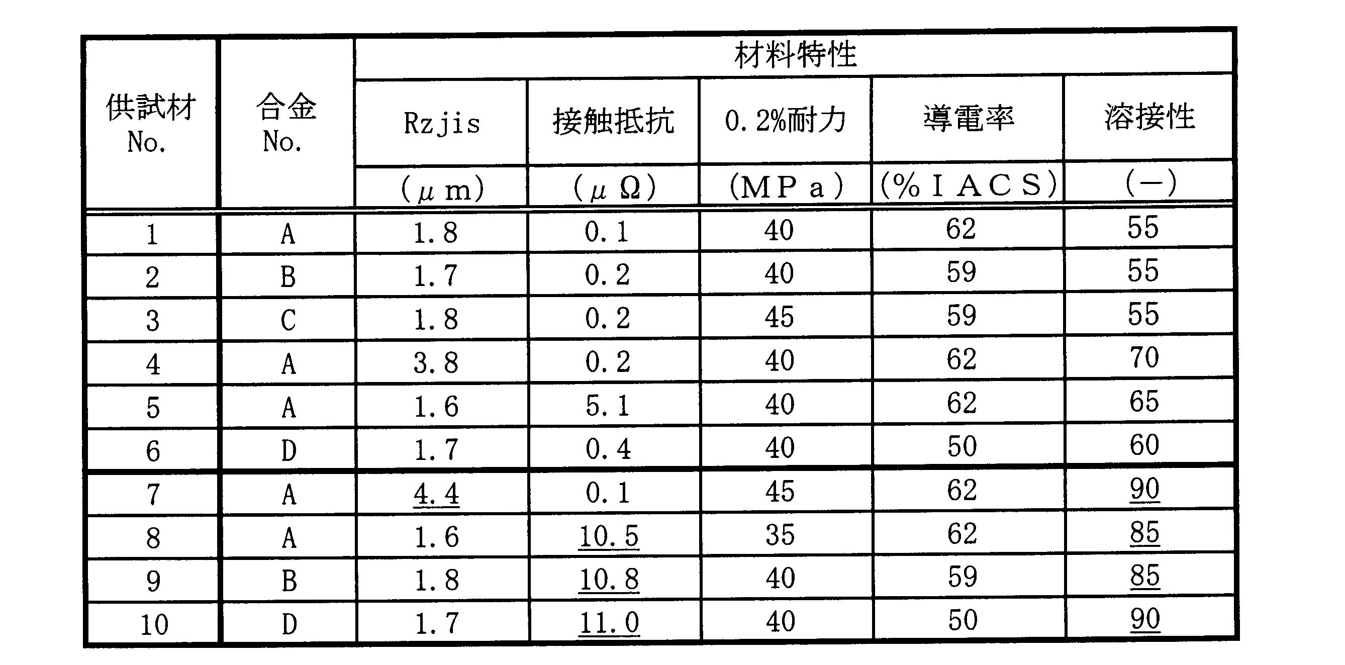
[結果の検討]
供試材1~6については、本発明の規定する要件を満たしていることから、優れた溶接性を発揮するという結果となった。
なお、供試材1~6については、0.2%耐力および導電率についても、好ましい結果が得られた。
供試材1~6については、本発明の規定する要件を満たしていることから、優れた溶接性を発揮するという結果となった。
なお、供試材1~6については、0.2%耐力および導電率についても、好ましい結果が得られた。
供試材7は、冷間圧延ロールの表面が粗かったことにより、十点平均粗さが4.0μmを超え、溶接性に優れないという結果となった。
供試材8は、仕上焼鈍の条件が不適切であったとともに洗浄も実施しなかったことにより、接触抵抗が10μΩを超え、溶接性に優れないという結果となった。
供試材9、10は、熱間圧延ロールのコーティングの厚さが厚かったとともに洗浄も実施しなかったことにより、接触抵抗が10μΩを超え、溶接性に優れないという結果となった。
供試材8は、仕上焼鈍の条件が不適切であったとともに洗浄も実施しなかったことにより、接触抵抗が10μΩを超え、溶接性に優れないという結果となった。
供試材9、10は、熱間圧延ロールのコーティングの厚さが厚かったとともに洗浄も実施しなかったことにより、接触抵抗が10μΩを超え、溶接性に優れないという結果となった。
以上の結果より、アルミニウム材として非熱処理型合金を用いた場合、板表面の十点平均粗さが4.0μm以下であるとともに、接触抵抗が10μΩ以下であると、優れた溶接性を発揮できることがわかった。
次に、アルミニウム材として、熱処理型合金を用いた場合について説明する。
[供試材の作製]
表3に示す組成のアルミニウム材(合金E、F)を、溶解し、半連続鋳造にて鋳塊を作製し、面削処理をした。この鋳塊に、均質化熱処理(温度:550℃、時間:4h)を行ったのち、圧延率99%の熱間圧延(開始温度:400℃、終了温度:300℃、終了板厚:2.2mm)を施して、熱間圧延板とした。その後、溶体化熱処理(処理前板厚:2.2mm、温度:550℃、時間:0s)を行った。そして、溶体化熱処理後、冷間圧延を施し、200℃、4時間保持する人工時効処理(処理前板厚:2.0mm)を施すことで、供試材(厚さ2.0mm)を作製した。
なお、供試材16については、溶体化熱処理の条件を、温度:550℃、時間:1hに変更して実施した。
表3に示す組成のアルミニウム材(合金E、F)を、溶解し、半連続鋳造にて鋳塊を作製し、面削処理をした。この鋳塊に、均質化熱処理(温度:550℃、時間:4h)を行ったのち、圧延率99%の熱間圧延(開始温度:400℃、終了温度:300℃、終了板厚:2.2mm)を施して、熱間圧延板とした。その後、溶体化熱処理(処理前板厚:2.2mm、温度:550℃、時間:0s)を行った。そして、溶体化熱処理後、冷間圧延を施し、200℃、4時間保持する人工時効処理(処理前板厚:2.0mm)を施すことで、供試材(厚さ2.0mm)を作製した。
なお、供試材16については、溶体化熱処理の条件を、温度:550℃、時間:1hに変更して実施した。
また、供試材11~16について、熱間圧延ロールのコーティングの厚さは、いずれも1~2μmの範囲に制御して実施した。一方、供試材17について、熱間圧延ロールのコーティングの厚さは、約4μmに制御して実施した。
なお、熱間圧延ロールのコーティング厚さの測定方法は、前記したとおりに行った。
なお、熱間圧延ロールのコーティング厚さの測定方法は、前記したとおりに行った。
そして、供試材11~13、15については、冷間圧延後であって人工時効処理前に、表記時間にて洗浄を行った。この洗浄作業は、苛性ソーダ等のアルカリ水溶液による洗浄(苛性ソーダ濃度:5質量%、温度:50℃、時間:0(洗浄せず)~60s)の後、硝酸によるデスマット処理(硝酸濃度:5質量%、温度:常温、時間:0(洗浄せず)~60s)を施すというものであった。
なお、熱間圧延ロールのコーティングの厚さ、洗浄の有無、洗浄の処理時間等を調整することにより、供試材の接触抵抗の値を変化させた。
また、冷間圧延ロールについて、表面の十点平均粗さが異なるものを用いることにより、供試材の表面の十点平均粗さを変化させた。
なお、熱間圧延ロールのコーティングの厚さ、洗浄の有無、洗浄の処理時間等を調整することにより、供試材の接触抵抗の値を変化させた。
また、冷間圧延ロールについて、表面の十点平均粗さが異なるものを用いることにより、供試材の表面の十点平均粗さを変化させた。
[評価]
評価の方法および基準について、実施例1と同じ内容については説明を省略し、相違する内容を中心に説明する。
評価の方法および基準について、実施例1と同じ内容については説明を省略し、相違する内容を中心に説明する。
(0.2%耐力)
0.2%耐力の値が130MPa以上であると、導電用アルミニウム板材(電気接続部品)としての耐力を確保できると評価した。
0.2%耐力の値が130MPa以上であると、導電用アルミニウム板材(電気接続部品)としての耐力を確保できると評価した。
(導電率)
導電率の値が40%IACS以上であると、導電用アルミニウム板材(電気接続部品)としての導電性能を確保できると評価した。
導電率の値が40%IACS以上であると、導電用アルミニウム板材(電気接続部品)としての導電性能を確保できると評価した。
詳細なアルミニウム材の成分、および材料特性(試験結果)を表3、4に示す。なお、表3、4において、本発明の構成を満たさないものについては、数値に下線を引いて示す。
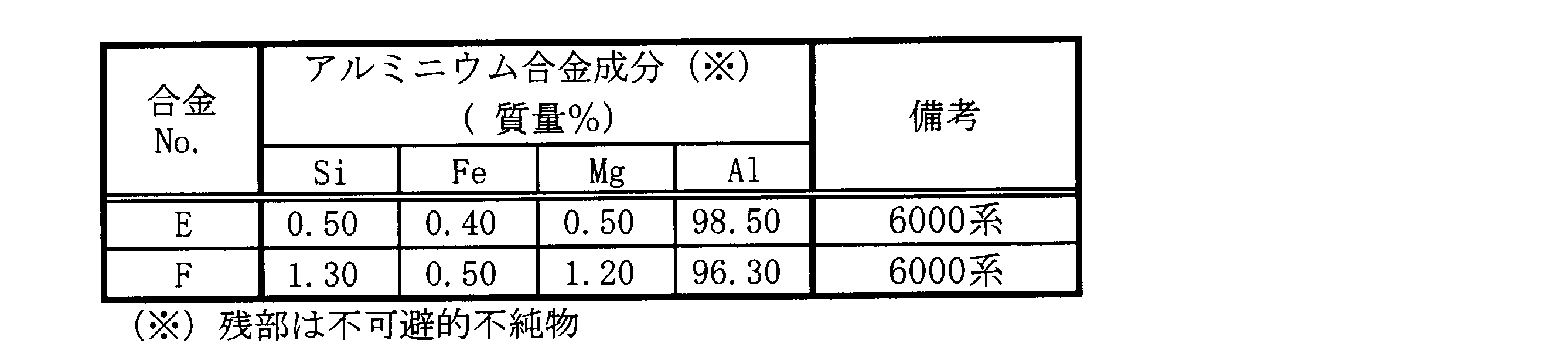
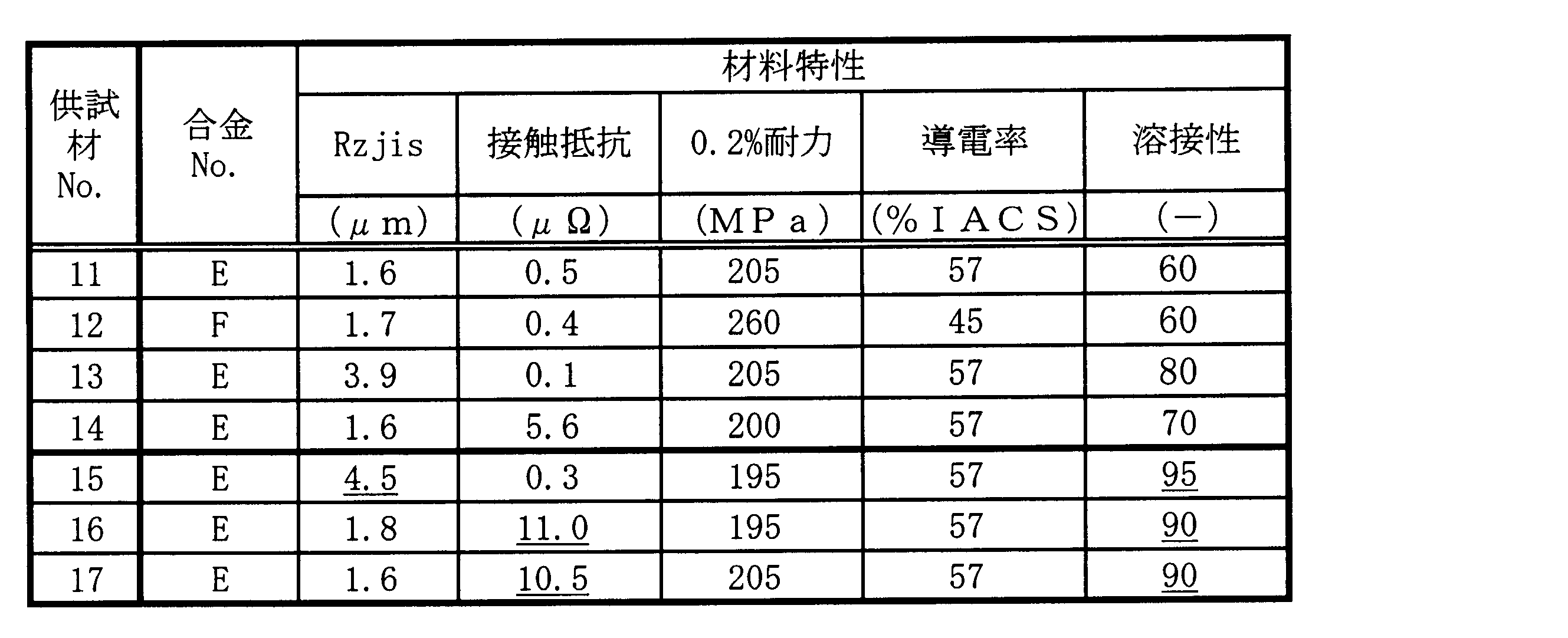
[結果の検討]
供試材11~14については、本発明の規定する要件を満たしていることから、優れた溶接性を発揮するという結果となった。
なお、供試材11~14については、0.2%耐力および導電率についても、好ましい結果が得られた。
供試材11~14については、本発明の規定する要件を満たしていることから、優れた溶接性を発揮するという結果となった。
なお、供試材11~14については、0.2%耐力および導電率についても、好ましい結果が得られた。
供試材15は、冷間圧延ロールの表面が粗かったことにより、十点平均粗さが4.0μmを超え、溶接性に優れないという結果となった。
供試材16は、溶体化熱処理の条件が不適切であるとともに洗浄も実施しなかったことにより、接触抵抗が10μΩを超えていたため、溶接性に優れないという結果となった。
供試材17は、熱間圧延ロールのコーティングの厚さが厚かったとともに洗浄も実施しなかったことにより、接触抵抗が10μΩを超え、溶接性に優れないという結果となった。
供試材16は、溶体化熱処理の条件が不適切であるとともに洗浄も実施しなかったことにより、接触抵抗が10μΩを超えていたため、溶接性に優れないという結果となった。
供試材17は、熱間圧延ロールのコーティングの厚さが厚かったとともに洗浄も実施しなかったことにより、接触抵抗が10μΩを超え、溶接性に優れないという結果となった。
以上の結果より、アルミニウム材として熱処理型合金を用いた場合、板表面の十点平均粗さが4.0μm以下であるとともに、接触抵抗が10μΩ以下であると、優れた溶接性を発揮できることがわかった。
本発明を詳細にまた特定の実施態様を参照して説明したが、本発明の精神と範囲を逸脱することなく様々な変更や修正を加えることができることは当業者にとって明らかである。
本出願は、2016年3月22日出願の日本特許出願(特願2016-057538)、2016年12月2日出願の日本特許出願(特願2016-235352)に基づくものであり、その内容はここに参照として取り込まれる。
本出願は、2016年3月22日出願の日本特許出願(特願2016-057538)、2016年12月2日出願の日本特許出願(特願2016-235352)に基づくものであり、その内容はここに参照として取り込まれる。
本発明の導電性アルミニウム板材は、各湯電動輸送機器における電気機器間の接続部材に有用である。
2 銅電極
3 オームメータ
10 供試材
20 アルミリボン
30 接合部
3 オームメータ
10 供試材
20 アルミリボン
30 接合部
Claims (9)
- アルミニウム又はアルミニウム合金からなり、
板表面の十点平均粗さが4.0μm以下であるとともに、接触抵抗が10μΩ以下であることを特徴とする導電用アルミニウム板材。 - 前記アルミニウム又はアルミニウム合金が非熱処理型合金であることを特徴とする請求項1に記載の導電用アルミニウム板材。
- 前記アルミニウム又はアルミニウム合金が熱処理型合金であることを特徴とする請求項1に記載の導電用アルミニウム板材。
- 前記アルミニウム又はアルミニウム合金が1000系のアルミニウムであることを特徴とする請求項2に記載の導電用アルミニウム板材。
- 前記アルミニウム又はアルミニウム合金が3000系のアルミニウム合金であることを特徴とする請求項2に記載の導電用アルミニウム板材。
- 前記アルミニウム又はアルミニウム合金が6000系のアルミニウム合金であることを特徴とする請求項3に記載の導電用アルミニウム板材。
- 前記アルミニウム又はアルミニウム合金が、
Si:0.25質量%以下、Fe:0.80質量%以下、Cu:0.20質量%以下、Mn:0.05質量%以下、Mg:0.05質量%以下、Zn:0.10質量%以下、Ti:0.05質量%以下、V:0.05質量%以下、Al:99.00質量%以上、残部:不可避的不純物、であることを特徴とする請求項4に記載の導電用アルミニウム板材。 - 前記アルミニウム又はアルミニウム合金が、
Si:0.6質量%以下、Fe:0.8質量%以下、Cu:0.30質量%以下、Mn:0.3~1.5質量%、Mg:1.3質量%以下、Zn:0.40質量%以下、Ti:0.20質量%以下、残部:Alおよび不可避的不純物、であることを特徴とする請求項5に記載の導電用アルミニウム板材。 - 前記アルミニウム又はアルミニウム合金が、
Si:0.30~1.30質量%、Fe:0.50質量%以下、Cu:0.10質量%以下、Mn:1.0質量%以下、Mg:0.35~1.20質量%、Cr:0.25質量%以下、Zn:0.20質量%以下、Ti:0.10質量%以下、B:0.06質量%以下、残部:Alおよび不可避的不純物、であることを特徴とする請求項6に記載の導電用アルミニウム板材。
Applications Claiming Priority (4)
| Application Number | Priority Date | Filing Date | Title |
|---|---|---|---|
| JP2016057538 | 2016-03-22 | ||
| JP2016-057538 | 2016-03-22 | ||
| JP2016235352A JP6181277B1 (ja) | 2016-03-22 | 2016-12-02 | 導電用アルミニウム板材 |
| JP2016-235352 | 2016-12-02 |
Publications (1)
| Publication Number | Publication Date |
|---|---|
| WO2017164082A1 true WO2017164082A1 (ja) | 2017-09-28 |
Family
ID=59604944
Family Applications (1)
| Application Number | Title | Priority Date | Filing Date |
|---|---|---|---|
| PCT/JP2017/010760 Ceased WO2017164082A1 (ja) | 2016-03-22 | 2017-03-16 | 導電用アルミニウム板材 |
Country Status (2)
| Country | Link |
|---|---|
| JP (1) | JP6181277B1 (ja) |
| WO (1) | WO2017164082A1 (ja) |
Cited By (2)
| Publication number | Priority date | Publication date | Assignee | Title |
|---|---|---|---|---|
| CN109385561A (zh) * | 2018-11-30 | 2019-02-26 | 黄冈师范学院 | 一种Al-Mg-Si-Zr铝合金管型母线的生产工艺 |
| CN114807702A (zh) * | 2022-03-23 | 2022-07-29 | 山东博源精密机械有限公司 | 一种Al-Mg-Fe系电机转子合金及其制备方法和应用 |
Families Citing this family (4)
| Publication number | Priority date | Publication date | Assignee | Title |
|---|---|---|---|---|
| JP6614305B1 (ja) * | 2018-09-21 | 2019-12-04 | 日本軽金属株式会社 | 一体型防爆弁成形用の電池蓋用アルミニウム合金板及びその製造方法 |
| CN117373728B (zh) * | 2022-06-30 | 2024-09-10 | 比亚迪股份有限公司 | 导电排、导电排组件及车用电气设备系统 |
| JP2024119162A (ja) | 2023-02-22 | 2024-09-03 | 株式会社Uacj | アルミニウム合金板、及びその製造方法 |
| JP2024121892A (ja) | 2023-02-28 | 2024-09-09 | 株式会社Uacj | 圧延用クラッドスラブ、圧延用クラッドスラブの製造方法、及びクラッド材の製造方法 |
Citations (3)
| Publication number | Priority date | Publication date | Assignee | Title |
|---|---|---|---|---|
| JPH0417901A (ja) * | 1990-05-14 | 1992-01-22 | Furukawa Alum Co Ltd | 溶接性に優れたAl又はAl合金板とその製造方法 |
| JP2015025147A (ja) * | 2013-07-24 | 2015-02-05 | 株式会社Uacj | アルミニウム合金製バスバー |
| JP2015034330A (ja) * | 2013-08-09 | 2015-02-19 | 株式会社神戸製鋼所 | 電気接続部品用アルミニウム合金板およびその製造方法 |
-
2016
- 2016-12-02 JP JP2016235352A patent/JP6181277B1/ja not_active Expired - Fee Related
-
2017
- 2017-03-16 WO PCT/JP2017/010760 patent/WO2017164082A1/ja not_active Ceased
Patent Citations (3)
| Publication number | Priority date | Publication date | Assignee | Title |
|---|---|---|---|---|
| JPH0417901A (ja) * | 1990-05-14 | 1992-01-22 | Furukawa Alum Co Ltd | 溶接性に優れたAl又はAl合金板とその製造方法 |
| JP2015025147A (ja) * | 2013-07-24 | 2015-02-05 | 株式会社Uacj | アルミニウム合金製バスバー |
| JP2015034330A (ja) * | 2013-08-09 | 2015-02-19 | 株式会社神戸製鋼所 | 電気接続部品用アルミニウム合金板およびその製造方法 |
Cited By (3)
| Publication number | Priority date | Publication date | Assignee | Title |
|---|---|---|---|---|
| CN109385561A (zh) * | 2018-11-30 | 2019-02-26 | 黄冈师范学院 | 一种Al-Mg-Si-Zr铝合金管型母线的生产工艺 |
| CN109385561B (zh) * | 2018-11-30 | 2020-10-23 | 黄冈师范学院 | 一种Al-Mg-Si-Zr铝合金管型母线的生产工艺 |
| CN114807702A (zh) * | 2022-03-23 | 2022-07-29 | 山东博源精密机械有限公司 | 一种Al-Mg-Fe系电机转子合金及其制备方法和应用 |
Also Published As
| Publication number | Publication date |
|---|---|
| JP6181277B1 (ja) | 2017-08-16 |
| JP2017172034A (ja) | 2017-09-28 |
Similar Documents
| Publication | Publication Date | Title |
|---|---|---|
| JP6181277B1 (ja) | 導電用アルミニウム板材 | |
| US9890438B2 (en) | Aluminum copper clad material | |
| CN103052729B (zh) | 铝合金导体及其制造方法 | |
| TWI415959B (zh) | 高強度高導電銅合金軋延板及其製造方法 | |
| JP4143662B2 (ja) | Cu−Ni−Si系合金 | |
| US20110186192A1 (en) | Copper alloy material for electric/electronic parts and method of producing the same | |
| KR101752108B1 (ko) | 도전용 알루미늄 합금판 및 그의 제조 방법 | |
| TWI330202B (en) | Copper alloy sheet material for electric and electronic parts | |
| JP6052829B2 (ja) | 電気電子部品用銅合金材 | |
| JP6034765B2 (ja) | 電気接続部品用アルミニウム合金板およびその製造方法 | |
| JP6265582B2 (ja) | 銅合金材およびその製造方法 | |
| JP6087413B1 (ja) | レーザー溶接性に優れた自動車バスバー用アルミニウム合金板 | |
| JP2018070908A (ja) | Cu−Zr−Sn−Al系銅合金板材および製造方法並びに通電部材 | |
| JP2010059543A (ja) | 銅合金材料 | |
| JP2011157607A (ja) | アルミニウム合金製導電体及びその製造方法 | |
| JP4976521B2 (ja) | プロジェクション溶接特性に優れたCu−Ni−Si系銅合金、及びその製造方法 | |
| JP2010130709A (ja) | アルミ線材接続体 | |
| JP2001131657A (ja) | 電気・電子部品用銅合金 | |
| JP2711957B2 (ja) | アプセットバット溶接用アルミニウム合金材 | |
| JP2013040393A (ja) | プロジェクション溶接特性に優れたCu−Ni−Si系銅合金、及びその製造方法 | |
| JP2010236038A (ja) | 錫めっきの耐熱剥離性に優れた銅合金板 | |
| JP2711956B2 (ja) | アプセットバット溶接用アルミニウム合金材 | |
| JP2002294362A (ja) | 耐アーク性に優れる銅合金板又は条 |
Legal Events
| Date | Code | Title | Description |
|---|---|---|---|
| NENP | Non-entry into the national phase |
Ref country code: DE |
|
| 121 | Ep: the epo has been informed by wipo that ep was designated in this application |
Ref document number: 17770124 Country of ref document: EP Kind code of ref document: A1 |
|
| 122 | Ep: pct application non-entry in european phase |
Ref document number: 17770124 Country of ref document: EP Kind code of ref document: A1 |