WO2017163733A1 - 操作装置 - Google Patents
操作装置 Download PDFInfo
- Publication number
- WO2017163733A1 WO2017163733A1 PCT/JP2017/006561 JP2017006561W WO2017163733A1 WO 2017163733 A1 WO2017163733 A1 WO 2017163733A1 JP 2017006561 W JP2017006561 W JP 2017006561W WO 2017163733 A1 WO2017163733 A1 WO 2017163733A1
- Authority
- WO
- WIPO (PCT)
- Prior art keywords
- pinch
- time
- mask
- fingers
- determination
- Prior art date
- Legal status (The legal status is an assumption and is not a legal conclusion. Google has not performed a legal analysis and makes no representation as to the accuracy of the status listed.)
- Ceased
Links
Images





Classifications
-
- G—PHYSICS
- G06—COMPUTING OR CALCULATING; COUNTING
- G06F—ELECTRIC DIGITAL DATA PROCESSING
- G06F3/00—Input arrangements for transferring data to be processed into a form capable of being handled by the computer; Output arrangements for transferring data from processing unit to output unit, e.g. interface arrangements
- G06F3/01—Input arrangements or combined input and output arrangements for interaction between user and computer
- G06F3/017—Gesture based interaction, e.g. based on a set of recognized hand gestures
-
- G—PHYSICS
- G06—COMPUTING OR CALCULATING; COUNTING
- G06F—ELECTRIC DIGITAL DATA PROCESSING
- G06F3/00—Input arrangements for transferring data to be processed into a form capable of being handled by the computer; Output arrangements for transferring data from processing unit to output unit, e.g. interface arrangements
- G06F3/01—Input arrangements or combined input and output arrangements for interaction between user and computer
- G06F3/048—Interaction techniques based on graphical user interfaces [GUI]
- G06F3/0487—Interaction techniques based on graphical user interfaces [GUI] using specific features provided by the input device, e.g. functions controlled by the rotation of a mouse with dual sensing arrangements, or of the nature of the input device, e.g. tap gestures based on pressure sensed by a digitiser
- G06F3/0488—Interaction techniques based on graphical user interfaces [GUI] using specific features provided by the input device, e.g. functions controlled by the rotation of a mouse with dual sensing arrangements, or of the nature of the input device, e.g. tap gestures based on pressure sensed by a digitiser using a touch-screen or digitiser, e.g. input of commands through traced gestures
- G06F3/04883—Interaction techniques based on graphical user interfaces [GUI] using specific features provided by the input device, e.g. functions controlled by the rotation of a mouse with dual sensing arrangements, or of the nature of the input device, e.g. tap gestures based on pressure sensed by a digitiser using a touch-screen or digitiser, e.g. input of commands through traced gestures for inputting data by handwriting, e.g. gesture or text
-
- G—PHYSICS
- G06—COMPUTING OR CALCULATING; COUNTING
- G06F—ELECTRIC DIGITAL DATA PROCESSING
- G06F3/00—Input arrangements for transferring data to be processed into a form capable of being handled by the computer; Output arrangements for transferring data from processing unit to output unit, e.g. interface arrangements
- G06F3/01—Input arrangements or combined input and output arrangements for interaction between user and computer
- G06F3/03—Arrangements for converting the position or the displacement of a member into a coded form
- G06F3/041—Digitisers, e.g. for touch screens or touch pads, characterised by the transducing means
- G06F3/0412—Digitisers structurally integrated in a display
-
- G—PHYSICS
- G06—COMPUTING OR CALCULATING; COUNTING
- G06F—ELECTRIC DIGITAL DATA PROCESSING
- G06F2203/00—Indexing scheme relating to G06F3/00 - G06F3/048
- G06F2203/048—Indexing scheme relating to G06F3/048
- G06F2203/04808—Several contacts: gestures triggering a specific function, e.g. scrolling, zooming, right-click, when the user establishes several contacts with the surface simultaneously; e.g. using several fingers or a combination of fingers and pen
Definitions
- the present invention relates to an operating device.
- An operation device includes a detection unit that detects an operation performed on an operation surface, and a determination of a pinch operation for a predetermined time when an operation of two operation fingers is detected by the detection unit.
- FIG. 1A is an explanatory diagram illustrating the inside of a vehicle in which the operation device according to the embodiment is installed.
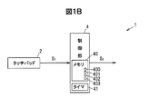
- FIG. 1B is a block diagram illustrating a configuration of the operating device.
- FIG. 2A is an explanatory diagram illustrating an example of a pinch operation performed on the operation surface of the operation device according to the embodiment.
- FIG. 2B is an explanatory diagram illustrating an example of a flick operation performed by two operation fingers.
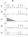
- FIG. 3 is a graph showing examples of the determination result of the pinch operation, the detection data of the pinch amount, and the mask time. In FIG. 3, (a) shows the determination result of the pinch operation when the mask time according to the comparative example is not set.
- FIG. 4 is a graph showing examples of the determination result of the pinch operation, the detection data of the pinch amount, and the mask time. In FIG. 4, (a) shows the determination of the pinch operation when the mask time according to the comparative example is not set.
- FIG. 5 is a flowchart illustrating an example of the operation of the controller device according to the embodiment.
- the operation device stops the determination of the pinch operation for a predetermined time when the operation of the two operation fingers is detected by the detection unit that detects the operation performed on the operation surface and the detection unit. And a determination unit.
- the operation device stops the determination of the pinch operation for a predetermined time, compared to the case where this configuration is not used, a minute change in the distance between the operation fingers in the flick operation performed with two operation fingers is pinched. An erroneous determination that is an operation can be suppressed.
- FIG. 1A is an explanatory view showing the inside of a vehicle in which the operating device according to the embodiment is installed
- FIG. 1B is a block diagram showing the configuration of the operating device.
- FIG. 2A is an explanatory diagram illustrating an example of a pinch operation performed on the operation surface of the controller device according to the embodiment
- FIG. 2B is an explanatory diagram illustrating an example of a flick operation performed by two operating fingers.
- the ratio between figures may be different from the actual ratio.
- main signals and information flows are indicated by arrows.
- the operation device 1 includes a touch pad 2 as a detection unit that detects an operation performed on the operation surface 20, and an operation of two operation fingers detected by the touch pad 2. And a control unit 4 as a determination unit that stops determination of the pinch operation for a predetermined time.
- the predetermined time is referred to as mask time 403, and the process of stopping the determination of the pinch operation is referred to as mask processing. Therefore, when the touch pad 2 detects an operation with two operating fingers, the control unit 4 performs a mask process for the mask time 403.
- the touch pad 2 is, for example, a touch sensor that detects a position on the operation surface 20 that is touched by an operator's operation finger.
- a touch sensor capable of detecting multi-touch such as a resistive film method, an infrared method, a SAW (Surface Acoustic Wave) method, and a capacitance method, can be used.
- the touch pad 2 of this embodiment is a capacitive touch sensor as an example.
- the pinch-out operation is an operation of expanding the two operation fingers 90 and the operation fingers 91 brought into contact with the operation surface 20 to enlarge a map image or the like according to the pinch amount.
- the pinch-in operation indicates, for example, an operation of reducing the map image or the like according to the pinch amount by bringing the two operation fingers 90 and the operation fingers 91 brought into contact with the operation surface 20 closer to each other.
- Detection points 900 and detection points 910 shown in FIG. 2A are coordinate points of the operation fingers 90 and 91 detected by the touch pad 2.
- the flick operation indicates an operation of paying the operation surface 20 with an operation finger, for example.
- the touch pad 2 detects a flick operation in which the operation surface 20 is paid with two operation fingers 92 and 93.
- the operator can send the map image displayed on the display device 85 in the direction in which the flick operation is performed by performing the flick operation with the two operation fingers 92 and 93.
- Detection points 920 and 930 shown in FIG. 2B are coordinate points of the operation finger 92 and the operation finger 93 detected by the touch pad 2.
- Touchpad 2 outputs to the control unit 4 the coordinate information of the detection point is a point on the operation surface 20 which detects the operation finger as the detection information S 1.
- the touch pad 2 for example, a plurality of drive electrodes to which a drive signal is supplied and a plurality of detection electrodes that read out capacitance formed between the driven drive electrodes are insulated from each other. Thus, it is disposed below the operation surface 20.
- Touchpad 2 obtains a detection point on the basis of the capacitance obtained by all combinations of the driving electrode and the detection electrode, periodically output as detection information S 1. As an example, this period is 20 ms.
- (Configuration of control unit 4) 3A is a graph showing an example of the determination result of the pinch operation when the mask time according to the comparative example is not set, and FIG. 3B is the relationship between the pinch amount and the time when the mask time is not set.
- (C) is a graph showing an example of the relationship between the mask time and the time according to the embodiment, and (d) is a pinch operation when the pinch determination is stopped during the mask time.
- (E) is a graph which shows an example of the pinch amount when the mask time is set.
- FIG. 4A is a graph showing an example of the determination result of the pinch operation when the mask time according to the comparative example is not set
- FIG. 4B is a graph of the pinch amount and time when the mask time is not set. It is a graph which shows an example of a relationship
- (c) is a graph which shows an example of the relationship between mask time and time when measurement of the mask time which concerns on embodiment is stopped
- (d) is mask time. It is a graph which shows an example of the determination result of the pinch operation at the time of being stopped
- (e) is a graph which shows an example of the amount of pinch when the mask time is stopped.
- the vertical axis indicates the occurrence of pinch and the absence.
- the vertical axis represents the absolute value of the pinch amount.
- the vertical axis represents the mask time 403.
- the horizontal axis represents time.
- the pinch amount is displayed for each period of reading of the capacitance.
- the control unit 4 includes, for example, a CPU (Central Processing Unit) that performs operations and processing on the acquired data according to a stored program, a RAM (Random Access Memory) that is a semiconductor memory, a ROM (Read Only Memory), and the like. Microcomputer. In this ROM, for example, a program for operating the control unit 4 is stored.
- the RAM is, for example, a memory 40 that temporarily stores calculation results and the like.
- the control unit 4 includes a timer 41 that measures the mask time 403.
- the pinch threshold 401 is a threshold for determining a pinch operation. This pinch threshold 401 is set lower than the mask time threshold 400. The control unit 4 determines that a pinch operation has been performed when the pinch amount is equal to or greater than the pinch threshold 401.
- the history information 402 stores the detected distance L between the operating fingers, the coordinates of the detection points, and the like in time series.
- the control unit 4 calculates the pinch amount based on the history information 402.
- the mask time 403 is the length of time for performing mask processing.
- the control unit 4 starts the timer 41 to measure the time, stops the timer 41 when the mask time 403 elapses, and stops the mask process.
- the mask time 403 is 100 to 200 ms as an example.
- the mask time 403 in this embodiment is 150 ms.
- the distance L between the detection point 920 of the operation finger 92 and the detection point 930 of the operation finger 93 changes slightly. This change may determine that a pinch operation has been performed.
- the pinch time threshold value 400 for determining the pinch operation within the mask time 403 may be a threshold value on the electronic device side to which the controller device 1 is connected, and is lower than this threshold value in order to increase sensitivity. It may be set.
- the controller device 1 of the present embodiment does not determine the pinch operation for a predetermined time (mask time 403).
- the pinch operation is not determined.
- the controller device 1 does not determine the pinch operation until the mask time 403 elapses from the start of the operation, so that it is possible to accurately determine the flick operation or the like based on the history information 402 during that time.
- control unit 4 stops the measurement of the mask time 403 and starts the determination of the pinch operation. It is configured.
- control unit 4 is configured to detect an obvious pinch operation performed within the mask time 403 using the mask time threshold value 400. Therefore, as shown in FIGS. 4C to 4E, the control unit 4 stops the mask process when a pinch amount equal to or greater than the mask time threshold value 400 is detected within the mask time 403, and performs the pinch operation. It is determined that has been made.
- Control unit 4 of the operating device 1 when the power supply of the vehicle 8 is turned on, periodically acquires detection information S 1 from the touch pad 2.
- Control unit 4 the detection point monitors Become two points on the basis of the detection information S 1 acquired. For example, when the number of detection points is one or the number of detection points is three or more, the control unit 4 determines a tracing operation or the like.
- control unit 4 in step 4 when the pinch amount than the mask time threshold 400 is small (Step4: No), no pinch operation, and outputs to the electronic device to generate an operation information S 2 which is a pinch amount zero (Step 7).
- the controller device 1 does not determine the pinch operation until the mask time 403 elapses after the start of the operation detection with the two operation fingers, and thus is performed with the two operation fingers based on the history information 402 during that time.
- a flick operation or the like can be accurately determined.
Landscapes
- Engineering & Computer Science (AREA)
- General Engineering & Computer Science (AREA)
- Theoretical Computer Science (AREA)
- Human Computer Interaction (AREA)
- Physics & Mathematics (AREA)
- General Physics & Mathematics (AREA)
- User Interface Of Digital Computer (AREA)
- Position Input By Displaying (AREA)
Abstract
操作装置1は、操作面20になされた操作を検出するタッチパッド2と、タッチパッド2によって二本の操作指の操作が検出された場合、予め定められた時間(マスク時間403)、ピンチ操作の判定を停止する制御部4と、を備えている。この制御部4は、マスク時間403内に二本の操作指間の距離Lの変化がピンチ時間しきい値400以上になると、マスク時間403の計測を停止してピンチ操作の判定を開始するように構成されている。
Description
本発明は、操作装置に関する。
タッチパネルによる操作部と、所定の画面上でタッチパネル上の接触を検知している位置を所定のポインタ画像で表示する表示手段と、ユーザからの操作に合わせてポインタ画像の位置を移動させ、画面上に示す制御手段と、を備えた情報表示装置(操作装置)が知られている(例えば、特許文献1参照。)。
この操作装置は、ユーザからの操作としてフリック操作やピンチ操作を検出することができる。
フリック操作とピンチ操作を検出する操作部を有する操作装置は、二本指で行われたフリック操作を検出するように構成することも可能である。しかしながら、この操作装置によれば、二本指で行われたフリック操作時に指の間隔が変わってフリック操作がピンチ操作と誤判定される可能性がある。
本発明の目的は、二本の操作指でなされたフリック操作において誤判定を抑制する操作装置を提供することにある。
本発明の一実施形態による操作装置は、操作面になされた操作を検出する検出部と、検出部によって二本の操作指の操作が検出された場合、予め定められた時間、ピンチ操作の判定を停止する判定部と、を備える。
本発明の一実施形態によれば、二本の操作指でなされたフリック操作において誤判定を抑制する操作装置を提供することができる。
(実施形態の要約)
実施形態に係る操作装置は、操作面になされた操作を検出する検出部と、検出部によって二本の操作指の操作が検出された場合、予め定められた時間、ピンチ操作の判定を停止する判定部と、を備えている。
実施形態に係る操作装置は、操作面になされた操作を検出する検出部と、検出部によって二本の操作指の操作が検出された場合、予め定められた時間、ピンチ操作の判定を停止する判定部と、を備えている。
操作装置は、予め定められた時間、ピンチ操作の判定を停止するので、この構成を用いない場合と比べて、二本の操作指でなされたフリック操作において操作指間の距離の微小変化がピンチ操作であるとされる誤判定を抑制することができる。
[実施形態]
(操作装置1の概要)
図1Aは、実施形態に係る操作装置が設置された車両内部を示す説明図であり、図1Bは、操作装置の構成を示すブロック図である。図2Aは、実施形態に係る操作装置の操作面になされたピンチ操作の一例を示す説明図であり、図2Bは、二本の操作指によってなされたフリック操作の一例を示す説明図である。なお、以下に記載する実施形態に係る各図において、図形間の比率は、実際の比率とは異なる場合がある。また図1Bでは、主な信号や情報の流れを矢印で示している。
(操作装置1の概要)
図1Aは、実施形態に係る操作装置が設置された車両内部を示す説明図であり、図1Bは、操作装置の構成を示すブロック図である。図2Aは、実施形態に係る操作装置の操作面になされたピンチ操作の一例を示す説明図であり、図2Bは、二本の操作指によってなされたフリック操作の一例を示す説明図である。なお、以下に記載する実施形態に係る各図において、図形間の比率は、実際の比率とは異なる場合がある。また図1Bでは、主な信号や情報の流れを矢印で示している。
操作装置1は、例えば、図1Aに示すように、車両8に搭載されている。この操作装置1は、例えば、車両8の運転席と助手席の間に伸びるフロアコンソール80に配置されている。また操作装置1は、例えば、導電性を有するペンや指による操作により、電子機器の表示部に表示されたカーソルの移動、表示されたアイコンの選択、決定、ドラッグ、ドロップなどの指示を行うことができるように構成されている。センターコンソール81に配置された表示装置85は、電子機器の表示部として機能する。本実施形態では、指(操作指)による操作について説明する。
操作装置1は、図1A及び1Bに示すように、操作面20になされた操作を検出する検出部としてのタッチパッド2と、タッチパッド2によって二本の操作指の操作が検出された場合、予め定められた時間、ピンチ操作の判定を停止する判定部としての制御部4と、を備えている。
なお以下では、予め定められた時間をマスク時間403、ピンチ操作の判定を停止する処理をマスク処理と記載する。よって制御部4は、タッチパッド2が二本の操作指による操作を検出すると、マスク時間403の間、マスク処理を行う。
(タッチパッド2の構成)
タッチパッド2は、例えば、操作者の操作指が接触した操作面20上の位置を検出するタッチセンサである。タッチパッド2としては、例えば、抵抗膜方式、赤外線方式、SAW(Surface Acoustic Wave)方式、静電容量方式などのマルチタッチを検出可能なタッチセンサを用いることが可能である。本実施形態のタッチパッド2は、一例として、静電容量方式のタッチセンサである。
タッチパッド2は、例えば、操作者の操作指が接触した操作面20上の位置を検出するタッチセンサである。タッチパッド2としては、例えば、抵抗膜方式、赤外線方式、SAW(Surface Acoustic Wave)方式、静電容量方式などのマルチタッチを検出可能なタッチセンサを用いることが可能である。本実施形態のタッチパッド2は、一例として、静電容量方式のタッチセンサである。
このタッチパッド2は、一例として、タッチ操作やタップ操作の他に複数の操作指によって行われるピンチ操作(ピンチアウト操作、ピンチイン操作)、フリック操作などを検出するように構成されている。
ピンチアウト操作は、例えば、図2Aに示すように、操作面20に接触させた二本の操作指90及び操作指91を広げて、地図画像などをピンチ量に応じて拡大する操作を示す。ピンチイン操作は、例えば、操作面20に接触させた二本の操作指90及び操作指91を近づけて、地図画像などをピンチ量に応じて縮小する操作を示す。図2Aに示す検出点900及び検出点910は、タッチパッド2が検出した操作指90及び操作指91の座標点である。
フリック操作は、例えば、操作指で操作面20を払う操作を示す。タッチパッド2は、例えば、図2Bに示すように、二本の操作指92及び操作指93で操作面20を払うフリック操作を検出する。操作者は、二本の操作指92及び操作指93によるフリック操作を行うことにより、一例として、表示装置85に表示された地図画像をフリック操作がなされた方向に送ることができる。図2Bに示す検出点920及び検出点930は、タッチパッド2が検出した操作指92及び操作指93の座標点である。
タッチパッド2は、操作指を検出した操作面20上の点である検出点の座標の情報を検出情報S1として制御部4に出力する。具体的には、タッチパッド2は、例えば、駆動信号が供給される複数の駆動電極と、駆動された駆動電極との間に形成される静電容量を読み出す複数の検出電極とが、互いに絶縁されて操作面20の下方に配置されている。タッチパッド2は、駆動電極と検出電極の全ての組み合わせで得られる静電容量に基づいて検出点を求め、検出情報S1として周期的に出力する。この周期は、一例として、20msである。
(制御部4の構成)
図3において(a)は、比較例に係るマスク時間を設定しない場合のピンチ操作の判定結果の一例を示すグラフであり、(b)は、マスク時間を設定しない場合のピンチ量と時間の関係の一例を示すグラフであり、(c)は、実施形態に係るマスク時間と時間の関係の一例を示すグラフであり、(d)は、マスク時間の間、ピンチ判定を停止した場合のピンチ操作の判定結果の一例を示すグラフであり、(e)は、マスク時間を設定した場合のピンチ量の一例を示すグラフである。
図3において(a)は、比較例に係るマスク時間を設定しない場合のピンチ操作の判定結果の一例を示すグラフであり、(b)は、マスク時間を設定しない場合のピンチ量と時間の関係の一例を示すグラフであり、(c)は、実施形態に係るマスク時間と時間の関係の一例を示すグラフであり、(d)は、マスク時間の間、ピンチ判定を停止した場合のピンチ操作の判定結果の一例を示すグラフであり、(e)は、マスク時間を設定した場合のピンチ量の一例を示すグラフである。
図4において、(a)は、比較例に係るマスク時間を設定しない場合のピンチ操作の判定結果の一例を示すグラフであり、(b)は、マスク時間を設定しない場合のピンチ量と時間の関係の一例を示すグラフであり、(c)は、実施形態に係るマスク時間の測定が停止された場合のマスク時間と時間の関係の一例を示すグラフであり、(d)は、マスク時間が停止された場合のピンチ操作の判定結果の一例を示すグラフであり、(e)は、マスク時間が停止された場合のピンチ量の一例を示すグラフである。
図3の(a)及び(d)、図4の(a)及び(d)は、縦軸がピンチ発生のあり、なしを示している。図3の(b)および(e)、図4の(b)及び(e)では、縦軸がピンチ量の絶対値である。図3の(c)及び図4の(c)は、縦軸がマスク時間403である。図3の(a)~(e)、図4の(a)~(e)では、横軸が時間である。また図3の(a)~(e)、図4の(a)~(e)では、例えば、静電容量の読み出しの周期ごとにピンチ量などが表示されている。
制御部4は、例えば、記憶されたプログラムに従って、取得したデータに演算、加工などを行うCPU(Central Processing Unit)、半導体メモリであるRAM(Random Access Memory)及びROM(Read Only Memory)などから構成されるマイクロコンピュータである。このROMには、例えば、制御部4が動作するためのプログラムが格納されている。RAMは、例えば、一時的に演算結果などを格納するメモリ40である。また制御部4は、マスク時間403を計測するタイマ41を備えている。
メモリ40には、例えば、図1Bに示すように、マスク時間しきい値400、ピンチしきい値401、履歴情報402及びマスク時間403が記憶されている。
マスク時間しきい値400は、マスク時間403内のマスク処理終了を判定するためのしきい値である。このマスク時間しきい値400は、ピンチ量と比較される。このピンチ量は、前の周期で検出された二本の操作指間の距離L1と今周期で検出された距離L2との差(=L1-L2)である。従って制御部4は、ピンチ量がプラスだとピンチイン操作、マイナスだとピンチアウト操作であると判定する。制御部4は、ピンチ量の絶対値を算出し、マスク処理中に、ピンチ量の絶対値がマスク時間しきい値400以上となった場合、ピンチ操作が行われたとしてマスク処理を停止する。
ピンチしきい値401は、ピンチ操作を判定するためのしきい値である。このピンチしきい値401は、マスク時間しきい値400よりも低く設定されている。制御部4は、ピンチ量がピンチしきい値401以上となるとピンチ操作がなされたと判定する。
履歴情報402は、検出された操作指間の距離L、及び検出点の座標などを時系列的に格納している。制御部4は、履歴情報402に基づいてピンチ量を算出する。
マスク時間403は、マスク処理を行う時間の長さである。制御部4は、タイマ41を起動して時間を計測させ、マスク時間403が経過するとタイマ41を停止させ、マスク処理を停止する。なおマスク時間403は、一例として、100~200msである。本実施形態のマスク時間403は、一例として、150msである。
図2Bに示すように、操作者が二本の操作指92及び操作指93によるフリック操作を行うと、操作指92の検出点920と操作指93の検出点930の距離Lが小さく変化し、この変化によってピンチ操作が行われたと判定される場合がある。
比較例として図3の(a)に示す「あり」は、図3の(b)に示すように、ピンチ操作を判定するためのしきい値が低いため、僅かなピンチ量でピンチ操作が判定される例を示している。このように、僅かなピンチ量でピンチ操作が判定されると、例えば、フリック操作を行ったつもりが地図画像の拡大や縮小、又は拡大と縮小が繰り返されることとなり、操作性が良くない。
もし図3の(b)に示すしきい値401が高く設定されれば僅かなピンチ量でピンチ操作を判定するようなことは減少するが、判定の感度が低くなって操作性が低下する。例えば、操作者が地図画像を拡大して所望の大きさになるように微調整を行う際に判定されない可能性がある。マスク時間403内にピンチ操作を判定するピンチ時間しきい値400は、操作装置1が接続される電子機器側のしきい値であってもよく、感度を高めるため、このしきい値よりも低く設定されてもよい。
本実施形態の操作装置1は、図3の(c)~(e)に示すように、予め定められた時間(マスク時間403)の間、ピンチ操作の判定を行わないので、僅かなピンチ量でピンチ操作が判定されない。そして操作装置1は、操作の開始からマスク時間403が経過するまでピンチ操作の判定を行わないことにより、その間の履歴情報402に基づいてフリック操作などを精度良く判定することが可能となる。
また制御部4は、ピンチ操作の判定を停止している間、二本の操作指間の距離Lの変化をゼロとした操作情報S2を出力する。従って電子機器側でピンチ操作が判定される場合、操作装置1は、一例として、当該操作情報S2を電子機器に出力し、マスク時間403の間、ピンチ操作の判定がなされないようにすることができる。
また制御部4は、マスク時間403内に二本の操作指間の距離Lの変化がピンチ時間しきい値400以上になると、マスク時間403の計測を停止してピンチ操作の判定を開始するように構成されている。
例えば、比較例として図4の(a)に示すようなピンチ量が検出された場合、図4の(b)に示すように、しきい値が低いと検出されたピンチ量の全てがピンチ発生「あり」と判定される。また制御部4がマスク時間403を設定してマスク処理を開始し、終了までピンチ操作の判定を停止すると、図4の(b)の三番目のピンチ量のように、明らかにピンチ操作を行っている操作をマスクしてしまう可能性がある。
そこで制御部4は、マスク時間しきい値400を用いて、マスク時間403内に行われた明らかなピンチ操作を検出するように構成されている。従って制御部4は、図4の(c)~(e)に示すように、マスク時間403内にマスク時間しきい値400以上のピンチ量が検出されると、マスク処理を停止させ、ピンチ操作がなされたと判定する。
以下に操作装置1の動作の一例について図5のフローチャートに従って説明する。ここでは、ピンチ操作の判定に関する動作のみ説明する。
(動作)
操作装置1の制御部4は、車両8の電源が投入されると、タッチパッド2から周期的に検出情報S1を取得する。制御部4は、取得した検出情報S1に基づいて検出点が2点になるか監視する。なお制御部4は、例えば、検出点が1点の場合や検出点が3点以上の場合、なぞり操作などの判定を行う。
操作装置1の制御部4は、車両8の電源が投入されると、タッチパッド2から周期的に検出情報S1を取得する。制御部4は、取得した検出情報S1に基づいて検出点が2点になるか監視する。なお制御部4は、例えば、検出点が1点の場合や検出点が3点以上の場合、なぞり操作などの判定を行う。
制御部4は、ステップ1の「Yes」が成立する、つまり検出点が2点であった場合(Step1:Yes)、マスク処理を開始する(Step2)。制御部4は、マスク処理のため、タイマ41を起動してマスク時間403の計測を開始する(Step3)。
制御部4は、2点の検出点に基づいて距離Lを算出し、履歴情報402としてメモリ40に記憶する。制御部4は、次の周期の検出情報S1に基づいてピンチ量を算出する。制御部4は、ピンチ量がマスク時間しきい値400以上であった場合(Step4:Yes)、ピンチ操作が行われたと判定し、タイマ41を制御してマスク時間403の計測を停止させてマスク処理を停止する(Step5)。
そして制御部4は、ピンチ量に基づいた操作情報S2を生成して電子機器に出力する(Step6)。この操作情報S2は、ピンチ操作ありを示している。制御部4は、マスク処理を停止した周期の次の周期の検出情報S1からピンチ操作の判定動作を行う。
ここでステップ4において制御部4は、マスク時間しきい値400よりピンチ量が小さい場合(Step4:No)、ピンチ操作なし、ピンチ量ゼロとした操作情報S2を生成して電子機器に出力する(Step7)。
そして制御部4は、タイマ41が測定している時間を確認する。制御部4は、マスク時間403が経過した場合(Step8:Yes)、マスク処理を停止する(Step9)。そして制御部4は、次の周期の検出情報S1とピンチしきい値401とに基づいてピンチ操作の判定を行う。
またステップ8において制御部4は、マスク時間403が経過していない場合(Step8:No)、次の周期の検出情報S1を取得し、当該検出情報S1から得られる操作指間の距離Lと履歴情報402から得られる前の周期の距離Lに基づいたピンチ量と、マスク時間しきい値400と、を比較する(Step4)。
(実施形態の効果)
本実施形態に係る操作装置は、誤判定を抑制することができる。具体的には、操作装置1は、マスク時間403の間、ピンチ操作の判定を停止するので、この構成を用いない場合と比べて、二本の操作指でなされたフリック操作において操作指間の距離Lの微小変化がピンチ操作であるとされる誤判定を抑制することができる。操作装置1は、誤判定が抑制されるので、操作性が良い。
本実施形態に係る操作装置は、誤判定を抑制することができる。具体的には、操作装置1は、マスク時間403の間、ピンチ操作の判定を停止するので、この構成を用いない場合と比べて、二本の操作指でなされたフリック操作において操作指間の距離Lの微小変化がピンチ操作であるとされる誤判定を抑制することができる。操作装置1は、誤判定が抑制されるので、操作性が良い。
操作装置1は、二本の操作指による操作検出の開始からマスク時間403が経過するまでピンチ操作の判定を行わないことにより、その間の履歴情報402に基づいて二本の操作指で行われたフリック操作などを精度良く判定することができる。
操作装置1は、マスク時間403の間、ピンチ量がゼロとする操作情報S2を電子機器に出力するので、電子機器側で、高感度でピンチ操作を判定する場合であっても、意図しない操作指間の距離の微小変化をピンチ操作と誤判定されることを抑制することができる。従って操作装置1は、誤判定の抑制と共に、電子機器の設定に応じた高感度なピンチ操作の検出を両立させることができる。
以上、本発明のいくつかの実施形態及び変形例を説明したが、これらの実施形態及び変形例は、一例に過ぎず、特許請求の範囲に係る発明を限定するものではない。これら新規な実施形態及び変形例は、その他の様々な形態で実施されることが可能であり、本発明の要旨を逸脱しない範囲で、種々の省略、置き換え、変更などを行うことができる。また、これら実施形態及び変形例の中で説明した特徴の組合せの全てが発明の課題を解決するための手段に必須であるとは限らない。さらに、これら実施形態及び変形例は、発明の範囲及び要旨に含まれると共に、特許請求の範囲に記載された発明とその均等の範囲に含まれる。
1 操作装置
2 タッチパッド
4 制御部
20 操作面
90~93 操作指
400 マスク時間しきい値
401 ピンチしきい値
403 マスク時間
2 タッチパッド
4 制御部
20 操作面
90~93 操作指
400 マスク時間しきい値
401 ピンチしきい値
403 マスク時間
Claims (6)
- 操作面になされた操作を検出する検出部と、
前記検出部によって二本の操作指の操作が検出された場合、予め定められた時間、ピンチ操作の判定を停止する判定部と、を備えた操作装置。 - 前記判定部は、前記二本の操作指間の距離の変化が第1のしきい値以上になると、前記予め定められた時間の計測を停止して前記ピンチ操作の判定を開始する、請求項1に記載の操作装置。
- 前記判定部は、前記ピンチ操作の判定を停止している間、前記二本の操作指間の距離の変化をゼロとした操作情報を出力する、請求項1又は2に記載の操作装置。
- 前記第1のしきい値は、前記操作装置が接続される電子機器のしきい値以下に設定されている、請求項2に記載の操作装置。
- 前記判定部は、前記予め定められた時間が経過した後、前記二本の操作指間の距離の変化が第2のしきい値以上になるとピンチ操作がなされたと判定する、請求項1に記載の操作装置。
- 前記第2のしきい値は前記第1のしきい値より低く設定される、請求項5に記載の操作装置。
Priority Applications (2)
| Application Number | Priority Date | Filing Date | Title |
|---|---|---|---|
| US16/079,826 US20190064932A1 (en) | 2016-03-23 | 2017-02-22 | Operation device |
| CN201780005146.7A CN108475173A (zh) | 2016-03-23 | 2017-02-22 | 操作装置 |
Applications Claiming Priority (2)
| Application Number | Priority Date | Filing Date | Title |
|---|---|---|---|
| JP2016058376A JP2017174071A (ja) | 2016-03-23 | 2016-03-23 | 操作装置 |
| JP2016-058376 | 2016-03-23 |
Publications (1)
| Publication Number | Publication Date |
|---|---|
| WO2017163733A1 true WO2017163733A1 (ja) | 2017-09-28 |
Family
ID=59901185
Family Applications (1)
| Application Number | Title | Priority Date | Filing Date |
|---|---|---|---|
| PCT/JP2017/006561 Ceased WO2017163733A1 (ja) | 2016-03-23 | 2017-02-22 | 操作装置 |
Country Status (4)
| Country | Link |
|---|---|
| US (1) | US20190064932A1 (ja) |
| JP (1) | JP2017174071A (ja) |
| CN (1) | CN108475173A (ja) |
| WO (1) | WO2017163733A1 (ja) |
Families Citing this family (1)
| Publication number | Priority date | Publication date | Assignee | Title |
|---|---|---|---|---|
| CN119512432A (zh) * | 2024-10-16 | 2025-02-25 | 重庆赛力斯凤凰智创科技有限公司 | 基于手势的缩放控制方法、装置、设备及存储介质 |
Citations (2)
| Publication number | Priority date | Publication date | Assignee | Title |
|---|---|---|---|---|
| JP2014130385A (ja) * | 2012-12-27 | 2014-07-10 | Tokai Rika Co Ltd | タッチ操作型入力装置 |
| JP2014178887A (ja) * | 2013-03-14 | 2014-09-25 | Sharp Corp | 情報処理装置、タッチパネル付ディスプレイ装置、情報処理方法及びプログラム |
Family Cites Families (4)
| Publication number | Priority date | Publication date | Assignee | Title |
|---|---|---|---|---|
| US7956847B2 (en) * | 2007-01-05 | 2011-06-07 | Apple Inc. | Gestures for controlling, manipulating, and editing of media files using touch sensitive devices |
| US20110304584A1 (en) * | 2009-02-23 | 2011-12-15 | Sung Jae Hwang | Touch screen control method and touch screen device using the same |
| JP5979916B2 (ja) * | 2012-03-07 | 2016-08-31 | キヤノン株式会社 | 情報処理装置およびその制御方法 |
| KR101741691B1 (ko) * | 2015-06-30 | 2017-05-30 | 현대자동차주식회사 | 차량 및 그 제어방법 |
-
2016
- 2016-03-23 JP JP2016058376A patent/JP2017174071A/ja active Pending
-
2017
- 2017-02-22 CN CN201780005146.7A patent/CN108475173A/zh active Pending
- 2017-02-22 US US16/079,826 patent/US20190064932A1/en not_active Abandoned
- 2017-02-22 WO PCT/JP2017/006561 patent/WO2017163733A1/ja not_active Ceased
Patent Citations (2)
| Publication number | Priority date | Publication date | Assignee | Title |
|---|---|---|---|---|
| JP2014130385A (ja) * | 2012-12-27 | 2014-07-10 | Tokai Rika Co Ltd | タッチ操作型入力装置 |
| JP2014178887A (ja) * | 2013-03-14 | 2014-09-25 | Sharp Corp | 情報処理装置、タッチパネル付ディスプレイ装置、情報処理方法及びプログラム |
Also Published As
| Publication number | Publication date |
|---|---|
| US20190064932A1 (en) | 2019-02-28 |
| CN108475173A (zh) | 2018-08-31 |
| JP2017174071A (ja) | 2017-09-28 |
Similar Documents
| Publication | Publication Date | Title |
|---|---|---|
| JP5589909B2 (ja) | 表示装置、表示装置のイベント切替え制御方法及びプログラム | |
| JP5832784B2 (ja) | タッチパネルシステムおよびそれを用いた電子機器 | |
| JP6284838B2 (ja) | タッチ式入力装置 | |
| CN202433855U (zh) | 信息处理装置 | |
| US8970542B2 (en) | Operation device and control method thereof | |
| US9983745B2 (en) | Touch sensor device and controller | |
| CN102902404B (zh) | 触摸面板 | |
| JP6323960B2 (ja) | 入力装置 | |
| JP5679595B2 (ja) | 電子機器及び座標判定方法 | |
| JP5668992B2 (ja) | 抵抗膜式タッチパネルを備えた電子機器 | |
| JP6724172B2 (ja) | 座標入力装置 | |
| JP7564733B2 (ja) | タッチ入力装置、タッチ入力方法、及びタッチ入力プログラム | |
| WO2017163733A1 (ja) | 操作装置 | |
| JP2018072952A (ja) | 操作装置 | |
| CN204203950U (zh) | 一种测试触摸屏的测试系统及触控笔 | |
| JP6014370B2 (ja) | タッチパネル装置、検出方法、及びプログラム | |
| KR20120029210A (ko) | 터치 스크린 장치 및 그 데이터 입력 방법 | |
| WO2014002315A1 (ja) | 操作装置 | |
| JP2012238210A (ja) | 入力装置 | |
| KR20140070264A (ko) | 터치 스크린 디스플레이 입력을 통한 객체 스크롤 방법 및 장치 | |
| JP5993511B1 (ja) | 操作装置 | |
| JP7002879B2 (ja) | タッチ式入力装置およびそのコントローラic | |
| JP2018120458A (ja) | 操作装置 | |
| JP2024175886A (ja) | 入力検出装置、入力検出方法、及び入力検出プログラム | |
| JP2017004405A (ja) | 操作装置 |
Legal Events
| Date | Code | Title | Description |
|---|---|---|---|
| NENP | Non-entry into the national phase |
Ref country code: DE |
|
| 121 | Ep: the epo has been informed by wipo that ep was designated in this application |
Ref document number: 17769779 Country of ref document: EP Kind code of ref document: A1 |
|
| 122 | Ep: pct application non-entry in european phase |
Ref document number: 17769779 Country of ref document: EP Kind code of ref document: A1 |