WO2017163497A1 - 焼成用トチ、及び焼成用トチを用いたハニカム構造体の製造方法 - Google Patents
焼成用トチ、及び焼成用トチを用いたハニカム構造体の製造方法 Download PDFInfo
- Publication number
- WO2017163497A1 WO2017163497A1 PCT/JP2016/086448 JP2016086448W WO2017163497A1 WO 2017163497 A1 WO2017163497 A1 WO 2017163497A1 JP 2016086448 W JP2016086448 W JP 2016086448W WO 2017163497 A1 WO2017163497 A1 WO 2017163497A1
- Authority
- WO
- WIPO (PCT)
- Prior art keywords
- torch
- firing
- honeycomb
- main body
- molded body
- Prior art date
- Legal status (The legal status is an assumption and is not a legal conclusion. Google has not performed a legal analysis and makes no representation as to the accuracy of the status listed.)
- Ceased
Links
Images




Classifications
-
- F—MECHANICAL ENGINEERING; LIGHTING; HEATING; WEAPONS; BLASTING
- F27—FURNACES; KILNS; OVENS; RETORTS
- F27D—DETAILS OR ACCESSORIES OF FURNACES, KILNS, OVENS OR RETORTS, IN SO FAR AS THEY ARE OF KINDS OCCURRING IN MORE THAN ONE KIND OF FURNACE
- F27D3/00—Charging; Discharging; Manipulation of charge
- F27D3/0021—Charging; Discharging; Manipulation of charge of ceramic ware
- F27D3/0022—Disposition of the charge
-
- B—PERFORMING OPERATIONS; TRANSPORTING
- B01—PHYSICAL OR CHEMICAL PROCESSES OR APPARATUS IN GENERAL
- B01D—SEPARATION
- B01D39/00—Filtering material for liquid or gaseous fluids
-
- B—PERFORMING OPERATIONS; TRANSPORTING
- B01—PHYSICAL OR CHEMICAL PROCESSES OR APPARATUS IN GENERAL
- B01D—SEPARATION
- B01D39/00—Filtering material for liquid or gaseous fluids
- B01D39/14—Other self-supporting filtering material ; Other filtering material
- B01D39/20—Other self-supporting filtering material ; Other filtering material of inorganic material, e.g. asbestos paper, metallic filtering material of non-woven wires
-
- B—PERFORMING OPERATIONS; TRANSPORTING
- B01—PHYSICAL OR CHEMICAL PROCESSES OR APPARATUS IN GENERAL
- B01D—SEPARATION
- B01D46/00—Filters or filtering processes specially modified for separating dispersed particles from gases or vapours
- B01D46/0001—Making filtering elements
-
- B—PERFORMING OPERATIONS; TRANSPORTING
- B01—PHYSICAL OR CHEMICAL PROCESSES OR APPARATUS IN GENERAL
- B01D—SEPARATION
- B01D46/00—Filters or filtering processes specially modified for separating dispersed particles from gases or vapours
- B01D46/24—Particle separators, e.g. dust precipitators, using rigid hollow filter bodies
- B01D46/2403—Particle separators, e.g. dust precipitators, using rigid hollow filter bodies characterised by the physical shape or structure of the filtering element
- B01D46/2418—Honeycomb filters
-
- B—PERFORMING OPERATIONS; TRANSPORTING
- B28—WORKING CEMENT, CLAY, OR STONE
- B28B—SHAPING CLAY OR OTHER CERAMIC COMPOSITIONS; SHAPING SLAG; SHAPING MIXTURES CONTAINING CEMENTITIOUS MATERIAL, e.g. PLASTER
- B28B11/00—Apparatus or processes for treating or working the shaped or preshaped articles
- B28B11/24—Apparatus or processes for treating or working the shaped or preshaped articles for curing, setting or hardening
- B28B11/243—Setting, e.g. drying, dehydrating or firing ceramic articles
-
- B—PERFORMING OPERATIONS; TRANSPORTING
- B28—WORKING CEMENT, CLAY, OR STONE
- B28B—SHAPING CLAY OR OTHER CERAMIC COMPOSITIONS; SHAPING SLAG; SHAPING MIXTURES CONTAINING CEMENTITIOUS MATERIAL, e.g. PLASTER
- B28B3/00—Producing shaped articles from the material by using presses; Presses specially adapted therefor
- B28B3/20—Producing shaped articles from the material by using presses; Presses specially adapted therefor wherein the material is extruded
-
- C—CHEMISTRY; METALLURGY
- C04—CEMENTS; CONCRETE; ARTIFICIAL STONE; CERAMICS; REFRACTORIES
- C04B—LIME, MAGNESIA; SLAG; CEMENTS; COMPOSITIONS THEREOF, e.g. MORTARS, CONCRETE OR LIKE BUILDING MATERIALS; ARTIFICIAL STONE; CERAMICS; REFRACTORIES; TREATMENT OF NATURAL STONE
- C04B35/00—Shaped ceramic products characterised by their composition; Ceramics compositions; Processing powders of inorganic compounds preparatory to the manufacturing of ceramic products
- C04B35/622—Forming processes; Processing powders of inorganic compounds preparatory to the manufacturing of ceramic products
- C04B35/64—Burning or sintering processes
-
- C—CHEMISTRY; METALLURGY
- C04—CEMENTS; CONCRETE; ARTIFICIAL STONE; CERAMICS; REFRACTORIES
- C04B—LIME, MAGNESIA; SLAG; CEMENTS; COMPOSITIONS THEREOF, e.g. MORTARS, CONCRETE OR LIKE BUILDING MATERIALS; ARTIFICIAL STONE; CERAMICS; REFRACTORIES; TREATMENT OF NATURAL STONE
- C04B38/00—Porous mortars, concrete, artificial stone or ceramic ware; Preparation thereof
- C04B38/0006—Honeycomb structures
-
- F—MECHANICAL ENGINEERING; LIGHTING; HEATING; WEAPONS; BLASTING
- F27—FURNACES; KILNS; OVENS; RETORTS
- F27D—DETAILS OR ACCESSORIES OF FURNACES, KILNS, OVENS OR RETORTS, IN SO FAR AS THEY ARE OF KINDS OCCURRING IN MORE THAN ONE KIND OF FURNACE
- F27D3/00—Charging; Discharging; Manipulation of charge
- F27D3/12—Travelling or movable supports or containers for the charge
-
- F—MECHANICAL ENGINEERING; LIGHTING; HEATING; WEAPONS; BLASTING
- F27—FURNACES; KILNS; OVENS; RETORTS
- F27D—DETAILS OR ACCESSORIES OF FURNACES, KILNS, OVENS OR RETORTS, IN SO FAR AS THEY ARE OF KINDS OCCURRING IN MORE THAN ONE KIND OF FURNACE
- F27D5/00—Supports, screens or the like for the charge within the furnace
- F27D5/0031—Treatment baskets for ceramic articles
-
- B—PERFORMING OPERATIONS; TRANSPORTING
- B01—PHYSICAL OR CHEMICAL PROCESSES OR APPARATUS IN GENERAL
- B01D—SEPARATION
- B01D2279/00—Filters adapted for separating dispersed particles from gases or vapours specially modified for specific uses
- B01D2279/30—Filters adapted for separating dispersed particles from gases or vapours specially modified for specific uses for treatment of exhaust gases from IC Engines
-
- B—PERFORMING OPERATIONS; TRANSPORTING
- B28—WORKING CEMENT, CLAY, OR STONE
- B28B—SHAPING CLAY OR OTHER CERAMIC COMPOSITIONS; SHAPING SLAG; SHAPING MIXTURES CONTAINING CEMENTITIOUS MATERIAL, e.g. PLASTER
- B28B3/00—Producing shaped articles from the material by using presses; Presses specially adapted therefor
- B28B3/20—Producing shaped articles from the material by using presses; Presses specially adapted therefor wherein the material is extruded
- B28B2003/203—Producing shaped articles from the material by using presses; Presses specially adapted therefor wherein the material is extruded for multi-channelled structures, e.g. honeycomb structures
Definitions
- the present invention relates to a firing torch and a method for manufacturing a honeycomb structure using the firing torch. More specifically, in order to fire an unfired honeycomb formed body in a firing furnace, a firing torch laid under the honeycomb formed body, and a method for manufacturing a honeycomb structure using the firing torch (hereinafter, It is simply referred to as “honeycomb structure manufacturing method”).
- a ceramic honeycomb structure (hereinafter simply referred to as a “honeycomb structure”) is prepared by preparing a molding material (kneaded material) and extruding it into a desired honeycomb shape using an extrusion molding machine. After finishing cutting, it is manufactured through a firing step of firing at a high temperature.
- the honeycomb formed body is placed on a shelf board with one molded body end face facing downward, and is put into the firing furnace together with the shelf board. Is done.
- a floor plate for firing called “tochi” is interposed between the shelf board and the honeycomb molded body to form the honeycomb molded body. The body and the shelf board are prevented from coming into direct contact.
- a disk-shaped member obtained by cutting a honeycomb structure obtained by firing a honeycomb fired body with a predetermined thickness is used.
- a torch called “press torch” obtained by press-molding a ceramic material and firing it may be used.
- These tochis are collectively defined herein as “firing tochis”.
- a material from extrusion molding to before firing is referred to as “honeycomb molded body”, and a material fired through the firing process is referred to as “honeycomb structure”.
- the extruded honeycomb formed body is introduced into a firing furnace set at a predetermined firing temperature, and a firing process is performed.
- firing shrinkage occurs along the longitudinal direction (axial direction) of the cells of the honeycomb formed body and the direction orthogonal to the longitudinal direction of the cells. Therefore, when the honeycomb formed body is placed on the firing torch, a firing shrinkage during firing causes a deviation between the upper surface of the firing torch (corresponding to the honeycomb placement surface) and the formed body end face of the honeycomb formed body. In some cases, defects such as “cell deformation” on the end face of the molded body and “break of partition walls” where the partition walls are divided may occur.
- the occurrence of catching between the end face of the formed body and the honeycomb mounting surface does not cause uniform firing shrinkage, and the shape of the end face of the formed body may be distorted.
- the “roundness” defect in which the shape of the end face of the formed body was not a perfect circle was obtained. It is known that the above-mentioned problems are particularly noticeable when the honeycomb formed body has thin partition walls or when firing a large honeycomb structure having a large honeycomb diameter.
- the firing torch since the firing torch is repeatedly used over a plurality of times, it is gradually deformed by being exposed to a high firing temperature in the firing furnace, and irregularities are formed on the honeycomb mounting surface of the firing torch. There was. When the firing torch having these irregularities is used, the above-mentioned problems such as cell deformation tend to occur more remarkably. Further, like a honeycomb structure for GPF (Gasoline Particulate Filter) used as a particulate removal filter for gasoline vehicles, it is easily deformed depending on the material used, and the surface shape of the firing torch in contact with the honeycomb molded body is intact. There was a risk of being transferred to the end face of the molded product and deteriorating product quality.
- GPF Gel Particulate Filter
- a torch (firing slat) that has been proposed to suppress the catch between the firing torch and the honeycomb mounting surface that comes into contact with the honeycomb formed body and to reduce the contact area.
- These tochis are formed between the honeycomb formed body and the firing torch in the firing process by flattening the honeycomb mounting surface (top surface of the torch) or by forming a curved surface that rises from the edge to the center. It is possible to manufacture a honeycomb structure in which the roundness defect is eliminated without the occurrence of firing shrinkage resistance or restraint and without causing cell deformation or partition breakage.
- An object of the present invention is to provide a firing torch that can be eliminated and a method for manufacturing a honeycomb structure.
- a torch for firing and a method for manufacturing a honeycomb structure that solve the above-mentioned problems.
- the honeycomb mounting surface includes a flat portion in contact with the end surface of the formed body, a curved portion formed around the flat portion, and a convex curved surface that protrudes from the side surface of the main body portion to the outer edge of the flat portion.
- a torch support portion that is provided below the torch main body portion and supports the torch main body portion, and the area of the honeycomb placement surface of the torch main body portion is determined by the torch support portion in contact with the torch main body portion.
- a firing torch whose value divided by the area of the torch support surface is in the range of 1.5 to 20.0 is placed in a state where the torch support portion is opposed to the shelf board on the shelf board arranged.
- the firing torch installation process to be installed The honeycomb molded body is placed on the firing torch with the body end surface facing downward, and the honeycomb molded body is placed in the firing furnace with the firing torch interposed between the honeycomb molded body and the shelf board.
- a method for manufacturing a honeycomb structure using a firing torch comprising a honeycomb molded body placing step for placing the honeycomb molded body inside.
- the firing torch according to the present invention can be used for solving the problems that occur during firing such as cell deformation and partition breakage, firing the honeycomb formed body, and manufacturing the honeycomb structure. Furthermore, according to the method for manufacturing a honeycomb structure of the present invention, it is possible to prevent a decrease in yield at the time of manufacturing the honeycomb structure, to reduce a manufacturing cost, and to improve manufacturing efficiency.
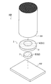
- FIG. 1 It is a perspective view which shows schematic structure of the torch for baking of this invention. It is a front view which shows schematic structure of the torch for baking. It is a disassembled perspective view which shows the honeycomb molded body before baking, the torch for baking, and a shelf board. It is explanatory drawing seen from the side which shows the torch for baking before baking, and a honeycomb molded object. It is sectional drawing seen from the side which shows the torch for firing after firing and the honeycomb structure.
- a firing torch 1 according to an embodiment of the present invention is provided with a substantially disc-like torch main body 2 and a lower part of the torch main body 2 to support the torch main body 2. And a substantially cylindrical torch support portion 3.
- the firing torch 1 is used in the firing step of the honeycomb structure manufacturing method in which the honeycomb formed body 100 is fired at a predetermined firing temperature to form a honeycomb structure (not shown).
- the torch main body portion 2 of the firing torch 1 has a honeycomb mounting surface 4 located on the upper surface side of the torch main body portion 2 and at least partly in contact with one of the molded body end surfaces 101 of the honeycomb molded body 100 to be fired.
- the main body lower surface 6 is provided on the lower surface side facing the honeycomb mounting surface 4 and in contact with the torch support surface 5 on the upper surface side of the torch support portion 3.
- the honeycomb mounting surface 4 is formed in the substantially same range as the torch support surface 5 of the torch support portion 3, and is parallel to the flat portion 7 along the planar main body lower surface 6 of the torch main body portion 2.
- a curved surface portion 10 formed of a convex curved surface formed around the flat portion 7 in a region deviated from the torch support surface 5 and raised from the main body portion side surface 8 of the torch main body portion 2 to the flat portion outer edge 9 of the flat portion 7; Have.
- the diameter D2 of the circular honeycomb mounting surface 4 of the torch main body 2 is formed smaller than the diameter D1 (corresponding to the honeycomb diameter) of the circular molded body end surface 101 of the honeycomb molded body 100 to be mounted. Yes.
- the torch support portion 3 includes a torch support surface 5 in contact with the torch main body portion 2 and a support portion lower surface 11 provided on the lower surface side facing the torch support surface 5 and in contact with the shelf plate 102.
- the diameter D3 of the torch support surface 5 of the torch support portion 3 is formed smaller than the diameter D2 of the honeycomb mounting surface 4 of the torch main body portion 2 supported by the torch support portion 3 (D2> D3). .
- the area S1 of the honeycomb mounting surface 4 is limited to a range of 1.5 times to 20.0 times the area S2 of the torch support surface 5.
- the above-described area ratio can be calculated from the diameters D2 and D3 since the honeycomb mounting surface 4 and the torch support surface 5 are each circular.
- the shapes of the honeycomb mounting surface 4 and the torch support surface 5 are not limited to the circular shape.
- the honeycomb mounting surface and the torch support surface each have a polygonal shape.
- the area ratio may be calculated based on the areas of the polygonal honeycomb mounting surface and the torch support surface, and the calculated value may be within the specified range.
- the honeycomb mounting surface 4 of the torch main body portion 2 is shown as being configured from the flat portion 7 and the curved surface portion 10, but is not limited thereto. It may be configured only from a flat part without the curved part, or may be configured only from a curved part without a flat part. In the former case, the contact area between the formed body end surface 101 of the honeycomb formed body 100 and the honeycomb mounting surface of the torch main body portion is increased as long as the area ratio defined above is satisfied. In the latter case, the contact area of the honeycomb formed body 100 with the end surface 101 of the formed body is small, but the honeycomb formed body 100 may be greatly shaken and unstable due to movement in the firing furnace or the like. However, as long as these fluctuations are within an allowable range, a honeycomb mounting surface composed only of a curved surface portion may be used.
- the height H3 from the lower surface 11 of the support portion in contact with the shelf board 102 to the torch support surface 5 is in the range of 0.5 mm to 5.0 mm, more preferably 1.0 mm. It is set in the range of ⁇ 4.0 mm. That is, when the torch main body portion 2 is placed on the torch support portion 3, the torch main body portion 2 has a clearance (clearance) of at least 0.5 mm or more from the upper surface of the shelf plate 102. Supported.
- the firing torch 1 is configured using a conventionally known ceramic material. Therefore, the region of the curved surface portion 10 of the torch main body portion 2 is subjected to a creep phenomenon peculiar to a ceramic material by being exposed at a high firing temperature in a firing furnace, and is deformed while maintaining gentle fluidity. In particular, as described above, a gap is formed between the curved surface portion 10 and the shelf plate 102, and there is no force to support the curved surface portion 10 from below. Therefore, due to the creep phenomenon, a force that gradually hangs down in accordance with its own weight is generated in the region (region of the curved surface portion 10) that is detached from the torch support portion 3 of the torch main body portion 2 (see FIG. 5).
- the honeycomb molded body 100 is deformed into a shape that protrudes upward in the axial direction (corresponding to the up and down direction in FIG. 5).
- the height H3 from the shelf plate 102 to the torch support surface 5 within the above range, even if the main body side surface 8 moves downward, the unevenness on the surface of the shelf plate 102 is reduced.
- the curved surface portion 10 can be kept in an optimum state without being affected. That is, an appropriate torch shape can be maintained by the creep phenomenon.
- the height H1 in the axial direction of the honeycomb formed body 100 and the side surface of the main body are respectively shown. 8 from the upper end 8b to the lower end 8a, the height H4 from the upper end 8b of the body side surface 8 before firing to the molded body end surface 101, and the honeycomb structure 103 from the upper end 8b of the body side surface 8 after firing.
- the height H5 to the structure end surface 104 is defined in this specification. As described above, when the honeycomb mounting surface of the torch main body portion does not have a curved surface portion, the height H4 from the upper end 8b before the firing to the molded body end surface 101 is 0 mm.
- the firing torch 1 of the present embodiment is formed from a ceramic material as described above.
- the material is not particularly limited, and for example, various materials used as a base material for a firing torch can be used. For example, it is possible to use a material that is converted into cordierite, silicon carbide, alumina, or the like by firing at a high temperature. Note that the firing torch 1 of the present embodiment uses a conventionally formed mullite material.
- the method for forming the firing torch 1 is not particularly limited.
- the honeycomb mounting surface can be cut to match the shape of the flat portion and the curved surface portion to obtain a firing torch having a desired shape. it can.
- the firing torch used in the firing process is a large amount, and performing the above-described cutting process for each of them may lead to complication of the production process of the firing torch and an increase in production cost.
- a press working mold formed in accordance with the shape of the firing torch is used, a ceramic material as a raw material is filled in the mold, and a desired press pressure is applied to form. It doesn't matter.
- a torch for firing can be produced by firing the torch molded body that has been punched from the mold. Thereby, ceramic prestoches can be mass-produced and used as a firing torch of the present invention.
- a torch for firing in which a torch main body portion and a torch support portion are integrally formed can be used. That is, in FIG. 3 etc., although the torch main-body part 2 and the torch support part 3 were each shown as a separate structure, you may not be limited to this. Moreover, after forming by a separate structure, the main body part lower surface 6 of the torch main body part 2 and the torch support surface 5 of the torch support part 3 may be joined with a desired joining material to form an integral structure. Thereby, the stability at the time of mounting the honeycomb molded object 100 and moving to a horizontal direction improves.
- the firing torch 1 of the present embodiment is set so that the surface roughness (Ra) of the flat portion 7 of the honeycomb mounting surface 4 is 10 ⁇ m or less.
- the surface roughness (Ra) is a value measured based on the measuring method described in JIS-B-0601.
- the flat portion 7 is a portion that is in direct contact with the formed body end surface 101 of the honeycomb formed body 100. In other words, depending on the presence or absence of fine irregularities on the flat portion 7, in other words, due to the smoothness of the flat portion 7, Particularly, it is caught on the firing torch 1 to inhibit uniform firing shrinkage and to cause problems such as cell deformation.
- the surface roughness (Ra) of the flat portion 7 is equal to or less than the above numerical value, it is possible to effectively avoid the occurrence of defects during firing.
- the torch main body 2 is placed on the shelf board 102 with the torch support 3 interposed, and the honeycomb placing surface 4 of the torch main body 2 is further provided.
- the substantially cylindrical honeycomb molded body 100 can be placed in an upright state by contacting at least a part of the molded body end surface 101 of the honeycomb molded body 100 (FIGS. 3 and 4).
- the honeycomb mounting surface 4 includes the flat portion 7 and the curved surface portion 10
- the mounting state when the honeycomb molded body 100 is mounted in an upright state is stable, and the honeycomb molded body 100 is molded.
- the contact area with the body end surface 101 can be made as small as possible.
- the horizontal movement in the baking furnace is stabilized.
- the surface roughness (Ra) of the flat portion 7 to 10 ⁇ m or less the molded body end surface 101 can be prevented from being caught during firing shrinkage.
- the occurrence of defects such as cell deformation and partition breakage is eliminated, uniform firing shrinkage is performed, and the roundness defect in the molded body end surface 101 does not occur.
- the outer peripheral region including the main body side surface 8 of the torch main body 2 is It is separated from the shelf board 102.
- the torch main body 2 formed from a ceramic material such as mullite or the like causes a creep phenomenon peculiar to the ceramic material, and compared with before firing. And a convex shape protruding upward.
- the honeycomb formed body 100 As a result, as the honeycomb formed body 100 is fired, the flat portion 7 is gradually narrowed, and the occurrence of defects such as cell deformation and partition wall breakage due to contact with the firing torch 1 is low. Become. As a result, it is possible to suppress a decrease in yield during the manufacture of the honeycomb structure and to stably fire the honeycomb formed body.
- the contact with the shelf board 102 is only the torch support portion 3 that is not in direct contact with the honeycomb molded body 100, the difference in firing shrinkage between the shelf board 102 and the firing torch 1 is the honeycomb molding. The firing of the body 100 is not affected.
- the firing torch of the present invention will be described based on the following examples, but the firing torch of the present invention is not limited to these examples.
- Honeycomb formed body A honeycomb formed body to be fired had a diameter D1 (honeycomb diameter) of 267 mm and an axial length H1 of 152 mm.
- the honeycomb molded body of (1) was made the same firing conditions such as firing temperature, and the like.
- Each firing step which is one step in the method for manufacturing a honeycomb structure, was performed.
- the following items were evaluated for the honeycomb structure obtained by firing and the torch for firing.
- the honeycomb formed body to be fired was obtained by extruding (molding process) a molding material (kneaded material) prepared at a predetermined blending ratio using a known extruder.
- the honeycomb molded body placing step of placing the honeycomb molded body with the molded body end face facing downward is included.
- a firing torch is interposed between the honeycomb formed body and the shelf board.
- the honeycomb formed body is put into the firing furnace, and firing is performed.
- the manufacturing of the honeycomb structure is completed (the manufacturing method of the honeycomb structure of the present invention).
- the same baking process was repeatedly used 15 times for each torch for baking.
- the torch for firing having no torch support portion can only withstand firing of the honeycomb formed body from one to several times. It was not possible to repeat the use 15 times or more like the firing torch of the present invention. In addition, partition wall breakage and cell deformation were frequently observed on the end face of the structure. As described above, by using the firing torch of the present invention, a honeycomb structure can be manufactured under stable conditions.
- the firing torch of the present invention can be particularly usefully used in a firing step which is one step of a method for producing a honeycomb structure for producing a ceramic honeycomb structure used as a catalyst carrier for automobile exhaust gas purification. . Furthermore, the honeycomb structure can be stably manufactured from the honeycomb formed body by the method for manufacturing a honeycomb structure using the firing torch.
Landscapes
- Engineering & Computer Science (AREA)
- Chemical & Material Sciences (AREA)
- Ceramic Engineering (AREA)
- Mechanical Engineering (AREA)
- General Engineering & Computer Science (AREA)
- Chemical Kinetics & Catalysis (AREA)
- Manufacturing & Machinery (AREA)
- Structural Engineering (AREA)
- Materials Engineering (AREA)
- Organic Chemistry (AREA)
- Inorganic Chemistry (AREA)
- Life Sciences & Earth Sciences (AREA)
- Geology (AREA)
- Physics & Mathematics (AREA)
- Geometry (AREA)
- Furnace Charging Or Discharging (AREA)
- Filtering Materials (AREA)
- Catalysts (AREA)
- Devices For Post-Treatments, Processing, Supply, Discharge, And Other Processes (AREA)
Abstract
焼成用トチ1は、ハニカム成形体100を焼成するために使用され、ハニカム成形体100及び棚板102の間に介設され、ハニカム成形体100の成形体端面101と少なくとも一部が接するハニカム載置面4を有し、ハニカム載置面4の上にハニカム成形体100を載置するトチ本体部2と、トチ本体部2の下方に設けられ、トチ本体部2支持するトチ支持部3とを備え、トチ本体部2のハニカム載置面4の面積S1を、トチ本体部2と接するトチ支持部3のトチ支持面5の面積S2で除した値が、1.5~20.0の範囲である。
Description
本発明は、焼成用トチ、及び焼成用トチを用いたハニカム構造体の製造方法に関する。更に詳しくは、未焼成のハニカム成形体を焼成炉内で焼成するために、ハニカム成形体の下に敷設される焼成用トチ、及び当該焼成用トチを用いたハニカム構造体の製造方法(以下、単に「ハニカム構造体の製造方法」と称する。)に関する。
従来、セラミックス製ハニカム構造体は、自動車排ガス浄化用触媒担体、ディーゼル微粒子除去フィルタ、或いは燃焼装置用蓄熱体等の広範な用途に使用されている。セラミックス製ハニカム構造体(以下、単に「ハニカム構造体」と称す。)は、成形材料(坏土)を調製し、押出成形機を用いて所望のハニカム形状に押出成形し、生切断、乾燥、仕上げ切断した後、高温で焼成する焼成工程を経て製造されている。
上記ハニカム構造体の製造方法で実施される焼成工程において、ハニカム成形体は、一方の成形体端面を下方に向けた状態で棚板の上に載置され、当該棚板とともに焼成炉内に投入される。このとき、ハニカム成形体が棚板に付着することを防止するために、棚板とハニカム成形体との間には、“トチ(栃)”と呼ばれる焼成用の敷板が介設され、ハニカム成形体と棚板とが直に接触することを防いでいる。トチには、例えば、ハニカム焼成体を焼成したハニカム構造体を所定の厚さで切断した円板状の部材が用いられる。また、繰り返し使用することで、トチが割れる不具合を防ぐため、セラミックス材料をプレス成形し、これを焼成した“プレストチ”と呼ばれるトチが用いられることもある。これらのトチを総称して、“焼成用トチ”と本明細書において定義する。また、押出成形から焼成前までのものを“ハニカム成形体”と呼称し、焼成工程を経て焼成されたものを“ハニカム構造体”と呼称する。
押出成形されたハニカム成形体は、所定の焼成温度に設定された焼成炉内に導入され、焼成工程が実施される。このとき、ハニカム成形体のセルの長手方向(軸方向)及びセルの長手方向に直交する方向に沿って、焼成収縮が発生する。そのため、ハニカム成形体を焼成用トチに載置した場合、焼成時の焼成収縮によって、焼成用トチの上面(ハニカム載置面に相当)とハニカム成形体の成形体端面との間でズレを生じ、成形体端面における“セルの変形”や、隔壁が分断された“隔壁切れ”等の不具合を発生することがあった。
更に、成形体端面とハニカム載置面との間に引っ掛かりが発生することで、焼成収縮が均等に行われず、成形体端面の形状に歪みが生じることがあった。その結果、円柱状のハニカム構造体の場合、成形体端面の形状が真円とならない“真円度”不良となった。上記不具合は、ハニカム成形体の隔壁が薄い場合や、ハニカム径の大きな大型ハニカム構造体の製造を行う焼成時に特に顕著となることが知られている。
一般に、焼成用トチは、複数回に亘って繰り返し使用されるため、焼成炉内で高温の焼成温度に晒されることで、徐々に変形し、焼成用トチのハニカム載置面に凹凸が形成されることがあった。これらの凹凸の有る焼成用トチを使用すると、セルの変形等の上記不具合がより顕著に発生する傾向があった。更に、ガソリン車用の微粒子除去フィルタとして用いられるGPF(Gasoline Particulate Filter)用のハニカム構造体のように、使用する材質によっては変形しやすく、ハニカム成形体と接した焼成用トチの表面形状がそのまま成形体端面に転写され、製品品質を低下させるおそれがあった。
上記不具合を解消するために、ハニカム成形体と接触する焼成用トチのハニカム載置面との間の引っ掛かりを抑制し、接触面積を小さく抑えることが可能なトチ(焼成用敷板)が既に提案されている(例えば、特許文献1または2参照。)。これらのトチは、ハニカム載置面(トチ上面)を平坦化したり、辺縁部から中央部にかけて隆起する曲面で形成したりすることで、焼成工程におけるハニカム成形体と焼成用トチとの間の焼成収縮の抵抗や拘束の発生を回避し、セルの変形や隔壁切れ等が生じることなく、真円度不良を解消したハニカム構造体を製造することができる。
しかしながら、特許文献1及び2において開示したトチを用いて場合でも、焼成後のハニカム構造体には、焼成条件によっては、セルの変形や隔壁切れなどが依然として発生する場合があった。特に、ハニカム径の大きな大型ハニカム構造体を製造する場合、焼成条件の調整が困難となり、上記不具合の発生が多くなることがあった。
そこで、本発明は、上記実情に鑑みてなされたものであり、セラミックス材料に発生する特有のクリープ現象を応用し、ハニカム載置面の形状を維持し、セルの変形や隔壁切れ等の不具合を解消可能な焼成用トチ、及びハニカム構造体の製造方法の提供を課題とするものである。
本発明によれば、上記課題を解決した焼成用トチ、及びハニカム構造体の製造方法が提供される。
[1] ハニカム成形体を焼成するために使用され、前記ハニカム成形体及び棚板の間に介設される焼成用トチであって、前記ハニカム成形体の成形体端面と少なくとも一部が接するハニカム載置面を有し、前記ハニカム載置面の上に前記ハニカム成形体を載置するトチ本体部と、前記トチ本体部の下方に設けられ、前記トチ本体部を支持するトチ支持部とを備え、前記トチ本体部の前記ハニカム載置面の面積を、前記トチ本体部と接する前記トチ支持部のトチ支持面の面積で除した値が、1.5~20.0の範囲である焼成用トチ。
[2] 前記トチ支持部は、前記棚板と接する支持部下面から前記トチ支持面までの高さが0.5mm~5.0mmの範囲である前記[1]に記載の焼成用トチ。
[3] 前記トチ本体部は、セラミックス製のプレストチである前記[1]または[2]に記載の焼成用トチ。
[4] 前記トチ本体部及び前記トチ支持部は、一体的に形成されている前記[1]~[3]のいずれかに記載の焼成用トチ。
[5] 前記ハニカム載置面は、前記成形体端面と接する平坦部と、前記平坦部の周囲に形成され、本体部側面から前記平坦部の外縁にかけて隆起する凸曲面で形成された曲面部とを有し、前記平坦部の表面粗さは、10μm以下である前記[1]~[4]のいずれかに記載の焼成用トチ。
[6] 前記トチ本体部の前記ハニカム載置面及び前記トチ支持部の前記トチ支持面の少なくとも一方は、円形状を呈する前記[1]~[5]のいずれかに記載の焼成用トチ。
[7] 前記トチ本体部及び前記トチ支持部の少なくとも一方は、ムライト質である前記[1]~[6]のいずれかに記載の焼成用トチ。
[8] 成形材料からハニカム成形体を押出成形する成形工程と、前記成形工程によって得られた前記ハニカム成形体を焼成する焼成工程とを具備し、前記焼成工程は、棚板を焼成炉内に配置する棚板配置工程と、前記ハニカム成形体の成形体端面と少なくとも一部が接するハニカム載置面を有し、前記ハニカム載置面の上に前記ハニカム成形体を載置可能なトチ本体部及び前記トチ本体部の下方に設けられ、前記トチ本体部を支持するトチ支持部を有し、前記トチ本体部の前記ハニカム載置面の面積を、前記トチ本体部と接する前記トチ支持部のトチ支持面の面積で除した値が、1.5~20.0の範囲である焼成用トチを、配置された前記棚板の上に前記トチ支持部を前記棚板に対向させた状態で設置する焼成用トチ設置工程と、前記成形体端面を下方に向けた状態で前記焼成用トチの上に前記ハニカム成形体を載せ、前記ハニカム成形体及び前記棚板の間に前記焼成用トチを介設した状態で前記ハニカム成形体を前記焼成炉内に載置するハニカム成形体載置工程とを具備する焼成用トチを用いたハニカム構造体の製造方法。
本発明の焼成用トチによれば、セルの変形や隔壁切れ等の焼成時に発生する不具合を解消し、ハニカム成形体を焼成し、ハニカム構造体を製造するために使用することができる。更に、本発明のハニカム構造体の製造方法によれば、ハニカム構造体の製造時における歩留まりの低下を防ぎ、製造コストの低減化を図り、製造効率を向上させることができる。
以下、図面を参照しつつ本発明の焼成用トチ、及び当該焼成用トチを用いた、ハニカム構造体の製造方法の実施の形態について詳述する。なお、本発明の焼成用トチ及びハニカム構造体の製造方法は、以下の実施の形態に限定されるものではなく、本発明の範囲を逸脱しない限りにおいて、種々の設計の変更、修正、及び改良等を加え得るものである。
本発明の一実施形態の焼成用トチ1は、図1~図5に示すように、略円板状のトチ本体部2と、トチ本体部2の下方に設けられ、トチ本体部2を支持する略円柱状のトチ支持部3とを主に備えている。焼成用トチ1は、ハニカム成形体100を所定の焼成温度で焼成し、ハニカム構造体(図示しない)を形成するハニカム構造体の製造方法の焼成工程で使用されるものである。
更に、焼成用トチ1のトチ本体部2は、焼成対象のハニカム成形体100の一方の成形体端面101と少なくとも一部が接する、トチ本体部2の上面側に位置するハニカム載置面4と、ハニカム載置面4と対向する下面側に位置し、かつトチ支持部3の上面側のトチ支持面5と接する本体部下面6とを備えている。
ここで、ハニカム載置面4は、トチ支持部3のトチ支持面5と略同一の範囲に形成され、トチ本体部2の平面状の本体部下面6に沿って平行な平坦部7と、トチ支持面5から外れた領域の平坦部7の周囲に形成され、トチ本体部2の本体部側面8から平坦部7の平坦部外縁9にかけて隆起する凸曲面で形成された曲面部10とを有している。なお、トチ本体部2の円形状のハニカム載置面4の直径D2は、載置するハニカム成形体100の円形状の成形体端面101の直径D1(ハニカム径に相当)よりも小さく形成されている。
一方、トチ支持部3は、トチ本体部2と接するトチ支持面5と、トチ支持面5と相対する下面側に設けられ、棚板102と接する支持部下面11とを備えている。ここで、トチ支持部3のトチ支持面5の直径D3は、トチ支持部3に支持されるトチ本体部2のハニカム載置面4の直径D2よりも小さく形成されている(D2>D3)。
更に、本実施形態の焼成用トチ1は、上記のハニカム載置面4及びトチ支持面5の面積比が規定されている。具体的に説明すると、それぞれ円形状のハニカム載置面4の直径D2及びトチ支持面5の直径D3に基づいて算出されたトチ本体部2のハニカム載置面4の面積S1(=(D2/2)2×π)を、トチ支持部3のトチ支持面5の面積S2(=(D3/2)2×π)で除した値が、1.5~20.0の範囲、より好ましくは、1.8~19.0の範囲となるように設定されている。これにより、トチ本体部2と、トチ本体部2を支持するトチ支持部3との面積比(=S1/S2)が規定される(図4参照)。
すなわち、トチ支持面5の面積S2に対して、ハニカム載置面4の面積S1が1.5倍から20.0倍の範囲に制限される。ここで、上記の面積比は、ハニカム載置面4及びトチ支持面5がそれぞれ円形状であるため、それぞれの直径D2,D3から算出することができる。しかしながら、ハニカム載置面4及びトチ支持面5の形状は、円形状に限定されるものではない。例えば、トチ本体部及びトチ支持部をそれぞれ多角柱状体で形成した場合、ハニカム載置面及びトチ支持面は、それぞれ多角形状となる。この場合、それぞれの多角形状のハニカム載置面及びトチ支持面の面積に基づいて、上記面積比を算出し、算出した値が上記規定した範囲内のものであれば構わない。
また、本実施形態の上記焼成用トチ1において、トチ本体部2のハニカム載置面4を、平坦部7及び曲面部10から構成するものについて示したが、これに限定されるものではなく、当該曲面部を有しない、平坦部のみから構成されるもの、或いは、平坦部を有しない、曲面部のみから構成されるものであっても構わない。前者の場合、ハニカム成形体100の成形体端面101と、トチ本体部のハニカム載置面との接触面積が大きくなるものの、上記規定した面積比を満たすものであれば構わない。また、後者の場合、ハニカム成形体100の成形体端面101との接触面積が小さくなるが、焼成炉内の移動等によってハニカム成形体100が大きく揺れ、不安定となる場合もある。しかしながら、これらの揺れが許容範囲のものであれば、曲面部のみからなるハニカム載置面を有するものであってもよい。
更に、本実施形態の焼成用トチ1は、棚板102と接する支持部下面11からトチ支持面5までの高さH3が、0.5mm~5.0mmの範囲、より好ましくは、1.0mm~4.0mmの範囲に設定されている。すなわち、トチ支持部3の上にトチ本体部2を載せた場合、トチ本体部2は、棚板102の上面から少なくとも0.5mm以上の隙間(クリアランス)を空けた状態でトチ本体部2が支持される。
焼成用トチ1は、従来から周知のセラミックス材料を用いて構成される。そのため、トチ本体部2の曲面部10の領域は、焼成炉内で高温の焼成温度で晒されることによって、セラミックス材料特有のクリープ現象を発生し、緩やかな流動性を保ちながら変形する。特に、曲面部10は、上記の通り、棚板102との間に隙間が形成されており、曲面部10を下方から支持する力は存在していない。そのため、クリープ現象によって、トチ本体部2のトチ支持部3から外れた領域(曲面部10の領域)は、自重に従って徐々に垂れ下がる力が発生する(図5参照)。その結果、ハニカム成形体100の軸方向(図5における紙面上下方向に相当)に沿って上側に凸状に隆起した形状に変形する。このとき、棚板102からトチ支持面5までの高さH3を、上記の範囲に規定することで、本体部側面8が下方に移動した場合であっても、棚板102の表面の凹凸に影響されず、曲面部10を最適な状態に保つ事ができる。すなわち、クリープ現象により適切なトチ形状を維持する事ができる。
なお、図4及び図5に示すように、上述した直径D1,D2,D3、及びトチ支持面5までの高さH3以外に、それぞれハニカム成形体100の軸方向の高さH1、本体部側面8の上端8bから下端8aまでの厚さH2、焼成前の本体部側面8の上端8bから成形体端面101までの高さH4、及び焼成後の本体部側面8の上端8bからハニカム構造体103の構造体端面104までの高さH5を、それぞれ本明細書において定義する。なお、先に述べたように、トチ本体部のハニカム載置面が曲面部を有しない場合、上記焼成前の上端8bから成形体端面101までの高さH4は、0mmとなる。
本実施形態の焼成用トチ1は、前述のようにセラミックス材料から形成される。その材質は、特に限定されるものではなく、例えば、焼成用トチの素地として使用される種々の材質を使用することができる。例えば、高温で焼成されることによって、コージェライト質、炭化珪素質、或いはアルミナ質等に変換される材料を用いることが可能である。なお、本実施形態の焼成用トチ1は、従来から周知のムライト質で形成されたものを使用している。
加えて、焼成用トチ1を形成する方法は、特に限定されるものではない。例えば、一般的な円板状の焼成用トチを形成した後、ハニカム載置面を平坦部及び曲面部の形状に合わせて切削加工等することにより、所望の形状の焼成用トチとすることができる。しかしながら、焼成工程において使用する焼成用トチは大量であり、それぞれについて上記切削加工を施すことは、焼成用トチの製造工程の煩雑化、及び製造コストの上昇につながるおそれがある。
そこで、例えば、焼成用トチの形状に応じて形成されたプレス加工用の成形型を使用し、原料となるセラミックス材料を成形型内に充填し、所望のプレス圧を加えて形成するものであっても構わない。プレス圧を加えた後、成形型から型抜きしたトチ成形体を焼成することにより、焼成用トチを製造することができる。これにより、セラミックス製のプレストチを大量生産することができ、本発明の焼成用トチとして使用することができる。
なお、上記のプレス加工の場合、トチ本体部及びトチ支持部を一体的に形成した焼成用トチとすることもできる。すなわち、図3等において、トチ本体部2及びトチ支持部3をそれぞれ別体構成として示したが、これに限定されないものであっても構わない。また、別体構成で形成した後に、トチ本体部2の本体部下面6及びトチ支持部3のトチ支持面5を所望の接合材で接合し、一体的構成としてもよい。これにより、ハニカム成形体100を載置し、水平方向に移動する際の安定性が向上する。
また、本実施形態の焼成用トチ1は、ハニカム載置面4の平坦部7の表面粗さ(Ra)が10μm以下となるように設定されている。ここで、表面粗さ(Ra)は、JIS-B-0601に記載した測定方法に基づいて測定された値である。平坦部7は、ハニカム成形体100の成形体端面101と直に接する部位であり、当該平坦部7に微細な凹凸の有無によって、換言すると、平坦部7の平滑性によって、成形体端面101が焼成用トチ1に引っ掛かり、均等な焼成収縮を阻害し、セルの変形等の不具合を発生させることに特に影響を与える。平坦部7の表面粗さ(Ra)を上記数値以下に規定することで、焼成時の不具合の発生を効果的に回避することができる。
上記構成を採用した焼成用トチ1を用いることにより、トチ本体部2を棚板102の上にトチ支持部3を介設した状態で載置し、更にトチ本体部2のハニカム載置面4に、ハニカム成形体100の成形体端面101の少なくとも一部を当接させることで、略円柱状のハニカム成形体100を直立した状態で載置することができる(図3及び図4)。
特に、ハニカム載置面4が平坦部7と曲面部10とから構成されるため、ハニカム成形体100を直立状態で載置した際の載置状態が安定し、かつ、ハニカム成形体100の成形体端面101との接触面積を可能な限り小さくすることができる。これにより、焼成炉内での水平移動が安定する。更に、平坦部7の表面粗さ(Ra)を10μm以下に抑えることにより、成形体端面101の焼成収縮時の引っ掛かりを防ぐことができる。その結果、セルの変形や隔壁切れ等の不具合の発生を解消し、均等な焼成収縮が行われ、成形体端面101における真円度の不良が発生することがない。
特に、トチ支持部3のトチ支持面5の面積に対して、トチ本体部2のハニカム載置面4の面積を大きくしたことにより、トチ本体部2の本体部側面8を含む外周領域が、棚板102から離間している。この状態で高温の焼成炉内にハニカム成形体100とともに導入されることで、ムライト質等のセラミックス材料から形成されたトチ本体部2は、セラミックス材料に特有なクリープ現象を生じ、焼成前と比べて上方に隆起した凸形状となる。その結果、ハニカム成形体100の焼成に伴って、平坦部7が徐々に狭まることになり、焼成用トチ1との接触によるハニカム成形体100のセルの変形や隔壁切れ等の不具合の発生が低くなる。これにより、ハニカム構造体の製造時の歩留まりの低下を抑制し、安定したハニカム成形体の焼成が可能となる。
このとき、棚板102との接触は、ハニカム成形体100と直に接していないトチ支持部3のみであるため、棚板102及び焼成用トチ1との間の焼成収縮の差が、ハニカム成形体100の焼成に影響を及ぼすことがない。
以下、本発明の焼成用トチについて、下記の実施例に基づいて説明するが、本発明の焼成用トチは、これらの実施例に限定されるものではない。
(1)ハニカム成形体
焼成対象のハニカム成形体は、直径D1(ハニカム径)が267mm、軸方向の長さH1が152mmのものをいずれも使用した。
焼成対象のハニカム成形体は、直径D1(ハニカム径)が267mm、軸方向の長さH1が152mmのものをいずれも使用した。
(2)焼成用トチの作製
ハニカム載置面の直径D2、及びトチ支持面の直径D3がそれぞれ異なり、D2/D3の面積比が本発明の範囲を満たす実施例1~10の焼成用トチ、及び当該面積比が本発明の範囲を逸脱する比較例1,2の焼成用トチを作製した。なお、比較例3~5は、トチ支持部を有さない従来の焼成用トチである。そのため、D2/D3の面積比等の値は有さない。これらは、いずれもプレストチであり、その材質は、ムライト質である。
ハニカム載置面の直径D2、及びトチ支持面の直径D3がそれぞれ異なり、D2/D3の面積比が本発明の範囲を満たす実施例1~10の焼成用トチ、及び当該面積比が本発明の範囲を逸脱する比較例1,2の焼成用トチを作製した。なお、比較例3~5は、トチ支持部を有さない従来の焼成用トチである。そのため、D2/D3の面積比等の値は有さない。これらは、いずれもプレストチであり、その材質は、ムライト質である。
(3)焼成工程の実施
上記実施例1~10、及び比較例1~5の焼成用トチを用い、上記(1)のハニカム成形体を焼成温度等の焼成条件を同一にして、本発明のハニカム構造体の製造方法における一工程である焼成工程をそれぞれ行った。焼成によって得られたハニカム構造体、及び焼成用トチについて下記の項目について評価した。なお、焼成対象となるハニカム成形体は、所定の配合比率に調製された成形材料(坏土)を周知の押出成形機を用いて押出成形(成形工程)したものを用いた。焼成工程の中には、焼成炉内に棚板を配置する棚板配置工程、上記の通り作製した焼成用トチを当該棚板の上に設置する焼成用トチ設置工程、更にその上に、一方の成形体端面を下方に向けた状態でハニカム成形体を載せるハニカム成形体載置工程を含んでいる。これにより、ハニカム成形体及び棚板の間に焼成用トチが介設された状態となる。係る状態で焼成炉内にハニカム成形体が投入され、焼成が実施される。これにより、ハニカム構造体の製造が完了する(本発明のハニカム構造体の製造方法)。なお、それぞれの焼成用トチは、同一の焼成工程を15回繰り返し使用した。それぞれ1回焼成後、5回焼成後、15回焼成後におけるハニカム構造体の本体部側面の上端から構造体端面までの高さH5及び構造体端面のセルの変形や隔壁切れの有無についてそれぞれ評価した。以下に評価項目及び評価基準について詳細を示す。
上記実施例1~10、及び比較例1~5の焼成用トチを用い、上記(1)のハニカム成形体を焼成温度等の焼成条件を同一にして、本発明のハニカム構造体の製造方法における一工程である焼成工程をそれぞれ行った。焼成によって得られたハニカム構造体、及び焼成用トチについて下記の項目について評価した。なお、焼成対象となるハニカム成形体は、所定の配合比率に調製された成形材料(坏土)を周知の押出成形機を用いて押出成形(成形工程)したものを用いた。焼成工程の中には、焼成炉内に棚板を配置する棚板配置工程、上記の通り作製した焼成用トチを当該棚板の上に設置する焼成用トチ設置工程、更にその上に、一方の成形体端面を下方に向けた状態でハニカム成形体を載せるハニカム成形体載置工程を含んでいる。これにより、ハニカム成形体及び棚板の間に焼成用トチが介設された状態となる。係る状態で焼成炉内にハニカム成形体が投入され、焼成が実施される。これにより、ハニカム構造体の製造が完了する(本発明のハニカム構造体の製造方法)。なお、それぞれの焼成用トチは、同一の焼成工程を15回繰り返し使用した。それぞれ1回焼成後、5回焼成後、15回焼成後におけるハニカム構造体の本体部側面の上端から構造体端面までの高さH5及び構造体端面のセルの変形や隔壁切れの有無についてそれぞれ評価した。以下に評価項目及び評価基準について詳細を示す。
(4)焼成後の高さH5の評価
各焼成回後おける本体部側面の上端から構造体端面までの高さH5は、1回焼成後の高さH5を基準値とし、5回焼成後及び15回焼成後の高さH5と基準値との差(変化量)が0.1mm未満のものを“A”、0.1mm~0.5mmの範囲のものを“B”、及び0.5mm以上のものを“C”として評価した。
各焼成回後おける本体部側面の上端から構造体端面までの高さH5は、1回焼成後の高さH5を基準値とし、5回焼成後及び15回焼成後の高さH5と基準値との差(変化量)が0.1mm未満のものを“A”、0.1mm~0.5mmの範囲のものを“B”、及び0.5mm以上のものを“C”として評価した。
(5)構造体端面の評価
各焼成回毎(1回、5回、15回)のハニカム構造体の構造体端面の形状を目視によって確認し、焼成収縮の際に発生した、特に、隔壁切れの有無を判定した。なお、隔壁切れやセルの変形がない場合を“A”、セルの変形が僅かなものは許容可能として“B”とし、大きな隔壁切れやセルの変形が有るものを“C”として、三段階の評価を行った。
各焼成回毎(1回、5回、15回)のハニカム構造体の構造体端面の形状を目視によって確認し、焼成収縮の際に発生した、特に、隔壁切れの有無を判定した。なお、隔壁切れやセルの変形がない場合を“A”、セルの変形が僅かなものは許容可能として“B”とし、大きな隔壁切れやセルの変形が有るものを“C”として、三段階の評価を行った。
実施例1~10、及び比較例1~5の焼成用トチの仕様、及び1回焼成後、5回焼成後、及び15回焼成後の高さH5及びその変化量、構造体端面の評価結果を下記表1に示す。

(考察:実施例1~10)
表1に示されるように、面積比が本発明の焼成用トチにおいて規定した範囲内の場合、5回焼成後、及び15回焼成後の高さH5の変化量が、1回焼成後の高さH5に対して0.1mm以下であり、更に1回焼成後、5回焼成後、及び15回焼成後のそれぞれのハニカム構造体の構造体端面に隔壁切れやセルの変形が存在せず“A”の評価結果を得た(実施例10を除く。)。これにより、本発明の焼成用トチを使用して焼成を行ったハニカム成形体は、焼成工程時に等方的な焼成収縮を行うことができることが確認された。更に、焼成用トチを繰り返し使用し、15回の焼成を行った場合でも、ハニカム成形体の焼成を良好に行うことができ、十分な耐久性を有することが確認された。
表1に示されるように、面積比が本発明の焼成用トチにおいて規定した範囲内の場合、5回焼成後、及び15回焼成後の高さH5の変化量が、1回焼成後の高さH5に対して0.1mm以下であり、更に1回焼成後、5回焼成後、及び15回焼成後のそれぞれのハニカム構造体の構造体端面に隔壁切れやセルの変形が存在せず“A”の評価結果を得た(実施例10を除く。)。これにより、本発明の焼成用トチを使用して焼成を行ったハニカム成形体は、焼成工程時に等方的な焼成収縮を行うことができることが確認された。更に、焼成用トチを繰り返し使用し、15回の焼成を行った場合でも、ハニカム成形体の焼成を良好に行うことができ、十分な耐久性を有することが確認された。
なお、支持部下面からトチ支持面までの高さH3が4mmの焼成用トチの場合(実施例10)、本体部側面の上端から成形体端面までの高さH4の値が、それ以外の実施例1~9の場合と比較して著しく大きな値であり、更に凹凸が大きかった。そのため、5回焼成後の高さH5の変化量の評価が“C”となるものの、実用上の問題とはならないことが示された。
(考察:比較例1~5)
一方、面積比が本発明の焼成用トチにおいて規定した範囲外の場合(比較例1,2)の場合、いずれも5回焼成後の高さH5の変化量の評価が“C”となり、更に5回焼成後の構造体端面において隔壁切れが発生した。したがって、面積比を1.5~20.0の範囲にすることの有効性が確認された。なお、5回焼成後の焼成用トチの高さH5の変化量が大きいため、それ以降の焼成を行っていない(表1中の“-”参照)。
一方、面積比が本発明の焼成用トチにおいて規定した範囲外の場合(比較例1,2)の場合、いずれも5回焼成後の高さH5の変化量の評価が“C”となり、更に5回焼成後の構造体端面において隔壁切れが発生した。したがって、面積比を1.5~20.0の範囲にすることの有効性が確認された。なお、5回焼成後の焼成用トチの高さH5の変化量が大きいため、それ以降の焼成を行っていない(表1中の“-”参照)。
一方、本発明の焼成用トチにおけるトチ支持部の構成を有しない、すなわち、従来の焼成用トチの場合(比較例3,5)は、比較例1,2と同様に、5回焼成後の高さH5が“C”となり、構造体端面に隔壁切れが確認された。そのため、比較例1,2と同様に、それ以降の焼成を行っていない。また、比較例4の焼成用トチの場合、1回焼成後において構造体端面に隔壁切れが発生したため、それ以降の焼成を行っていない。
上記示したように、面積比が本発明の範囲から逸脱している場合、或いはトチ支持部を有しない焼成用トチは、1回から数回程度のハニカム成形体の焼成にしか耐え得ることができず、本発明の焼成用トチのように、15回以上の繰り返しの使用を行うことができなかった。また、構造体端面に隔壁切れやセルの変形の発生が多く認められた。上記示す通り本発明の焼成用トチを用いることで、安定した条件でハニカム構造体を製造することができる。
本発明の焼成用トチは、自動車排ガス浄化用触媒担体等として使用されるセラミックスハニカム構造体を製造するためのハニカム構造体の製造方法の一工程である焼成工程において特に有用に使用することができる。更に、当該焼成用トチを用いたハニカム構造体の製造方法により、ハニカム成形体からハニカム構造体を安定的に製造することが可能となる。
1:焼成用トチ、2:トチ本体部、3:トチ支持部、4:ハニカム載置面、5:トチ支持面、6:本体部下面、7:平坦部、8:本体部側面、8a:下端、8b:上端、9:平坦部外縁、10:曲面部、11:支持部下面、100:ハニカム成形体、101:成形体端面、102:棚板、103:ハニカム構造体、104:構造体端面、D1:成形体端面の直径、D2:ハニカム載置面の直径、D3:トチ支持面の直径、H1:ハニカム成形体の軸方向の長さ、H2:本体部側面の厚さ、H3:支持部下面からトチ支持面までの高さ、H4:焼成前の本体部側面の上端から成形体端面までの高さ、H5:焼成後の本体部側面の上端から構造体端面までの高さ、S1:ハニカム載置面の面積、S2:トチ支持面の面積。
Claims (8)
- ハニカム成形体を焼成するために使用され、前記ハニカム成形体及び棚板の間に介設される焼成用トチであって、
前記ハニカム成形体の成形体端面と少なくとも一部が接するハニカム載置面を有し、前記ハニカム載置面の上に前記ハニカム成形体を載置するトチ本体部と、
前記トチ本体部の下方に設けられ、前記トチ本体部を支持するトチ支持部と
を備え、
前記トチ本体部の前記ハニカム載置面の面積を、前記トチ本体部と接する前記トチ支持部のトチ支持面の面積で除した値が、1.5~20.0の範囲である焼成用トチ。 - 前記トチ支持部は、
前記棚板と接する支持部下面から前記トチ支持面までの高さが0.5~5.0mmの範囲である請求項1に記載の焼成用トチ。 - 前記トチ本体部は、
セラミックス製のプレストチである請求項1または2に記載の焼成用トチ。 - 前記トチ本体部及び前記トチ支持部は、
一体的に形成されている請求項1~3のいずれか一項に記載の焼成用トチ。 - 前記ハニカム載置面は、
前記成形体端面と接する平坦部と、
前記平坦部の周囲に形成され、本体部側面から前記平坦部の外縁にかけて隆起する凸曲面で形成された曲面部と
を有し、
前記平坦部の表面粗さは、
10μm以下である請求項1~4のいずれか一項に記載の焼成用トチ。 - 前記トチ本体部の前記ハニカム載置面及び前記トチ支持部の前記トチ支持面の少なくとも一方は、
円形状を呈する請求項1~5のいずれか一項に記載の焼成用トチ。 - 前記トチ本体部及び前記トチ支持部の少なくとも一方は、
ムライト質である請求項1~6のいずれか一項に記載の焼成用トチ。 - 成形材料からハニカム成形体を押出成形する成形工程と、
前記成形工程によって得られた前記ハニカム成形体を焼成する焼成工程と
を具備し、
前記焼成工程は、
棚板を焼成炉内に配置する棚板配置工程と、
前記ハニカム成形体の成形体端面と少なくとも一部が接するハニカム載置面を有し、前記ハニカム載置面の上に前記ハニカム成形体を載置可能なトチ本体部及び前記トチ本体部の下方に設けられ、前記トチ本体部を支持するトチ支持部を有し、前記トチ本体部の前記ハニカム載置面の面積を、前記トチ本体部と接する前記トチ支持部のトチ支持面の面積で除した値が、1.5~20.0の範囲である焼成用トチを、配置された前記棚板の上に前記トチ支持部を前記棚板に対向させた状態で設置する焼成用トチ設置工程と、
前記成形体端面を下方に向けた状態で前記焼成用トチの上に前記ハニカム成形体を載せ、前記ハニカム成形体及び前記棚板の間に前記焼成用トチを介設した状態で前記ハニカム成形体を前記焼成炉内に載置するハニカム成形体載置工程と
を具備する焼成用トチを用いたハニカム構造体の製造方法。
Priority Applications (4)
| Application Number | Priority Date | Filing Date | Title |
|---|---|---|---|
| JP2018506765A JPWO2017163497A1 (ja) | 2016-03-24 | 2016-12-07 | 焼成用トチ、及び焼成用トチを用いたハニカム構造体の製造方法 |
| DE112016006636.8T DE112016006636T5 (de) | 2016-03-24 | 2016-12-07 | Brenneinsatz und Verfahren zur Herstellung einer Wabenstruktur unter Verwendung des Brenneinsatzes |
| CN201680081762.6A CN108779036A (zh) | 2016-03-24 | 2016-12-07 | 烧成用垫板、以及使用了烧成用垫板的蜂窝结构体的制造方法 |
| US16/102,918 US20180363981A1 (en) | 2016-03-24 | 2018-08-14 | Setter for firing, and method for manufacturing honeycomb structure using setter for firing |
Applications Claiming Priority (2)
| Application Number | Priority Date | Filing Date | Title |
|---|---|---|---|
| JP2016-060437 | 2016-03-24 | ||
| JP2016060437 | 2016-03-24 |
Related Child Applications (1)
| Application Number | Title | Priority Date | Filing Date |
|---|---|---|---|
| US16/102,918 Continuation US20180363981A1 (en) | 2016-03-24 | 2018-08-14 | Setter for firing, and method for manufacturing honeycomb structure using setter for firing |
Publications (1)
| Publication Number | Publication Date |
|---|---|
| WO2017163497A1 true WO2017163497A1 (ja) | 2017-09-28 |
Family
ID=59899927
Family Applications (1)
| Application Number | Title | Priority Date | Filing Date |
|---|---|---|---|
| PCT/JP2016/086448 Ceased WO2017163497A1 (ja) | 2016-03-24 | 2016-12-07 | 焼成用トチ、及び焼成用トチを用いたハニカム構造体の製造方法 |
Country Status (5)
| Country | Link |
|---|---|
| US (1) | US20180363981A1 (ja) |
| JP (1) | JPWO2017163497A1 (ja) |
| CN (1) | CN108779036A (ja) |
| DE (1) | DE112016006636T5 (ja) |
| WO (1) | WO2017163497A1 (ja) |
Citations (4)
| Publication number | Priority date | Publication date | Assignee | Title |
|---|---|---|---|---|
| JPS62202870A (ja) * | 1986-02-20 | 1987-09-07 | 日本碍子株式会社 | セラミツクスハニカム構造体の焼成方法 |
| JP2011213499A (ja) * | 2010-03-31 | 2011-10-27 | Ngk Insulators Ltd | 焼成用敷板 |
| JP2012521345A (ja) * | 2009-03-24 | 2012-09-13 | サン−ゴバン サントル ドゥ ルシェルシェ エ デトゥードゥ ユーロペン | ハニカム構造を硬化させるための方法及び基材 |
| WO2014038485A1 (ja) * | 2012-09-05 | 2014-03-13 | 住友化学株式会社 | ハニカム構造体の製造方法 |
Family Cites Families (6)
| Publication number | Priority date | Publication date | Assignee | Title |
|---|---|---|---|---|
| JP3364223B2 (ja) * | 1993-02-02 | 2003-01-08 | 日本碍子株式会社 | 焼成用敷板及びそれを用いるセラミック成形体の焼成方法 |
| JP3611474B2 (ja) | 1999-03-24 | 2005-01-19 | 日本碍子株式会社 | 焼成用敷板 |
| JP2003082403A (ja) | 2001-09-11 | 2003-03-19 | Ngk Insulators Ltd | 焼成用敷板 |
| ZA200703380B (en) * | 2004-09-27 | 2008-09-25 | Ngk Insulators Ltd | Setter used in firing and method for firing of formed honeycomb body using the setter |
| WO2008053647A1 (en) * | 2006-10-31 | 2008-05-08 | Ngk Insulators, Ltd. | Method of honeycomb molding pretreatment for burning and system for honeycomb molding pretreatment for burning |
| CN203413958U (zh) * | 2013-06-25 | 2014-01-29 | Ngk(苏州)环保陶瓷有限公司 | 蜂窝结构体烧成用烧成台 |
-
2016
- 2016-12-07 CN CN201680081762.6A patent/CN108779036A/zh active Pending
- 2016-12-07 WO PCT/JP2016/086448 patent/WO2017163497A1/ja not_active Ceased
- 2016-12-07 JP JP2018506765A patent/JPWO2017163497A1/ja active Pending
- 2016-12-07 DE DE112016006636.8T patent/DE112016006636T5/de not_active Withdrawn
-
2018
- 2018-08-14 US US16/102,918 patent/US20180363981A1/en not_active Abandoned
Patent Citations (4)
| Publication number | Priority date | Publication date | Assignee | Title |
|---|---|---|---|---|
| JPS62202870A (ja) * | 1986-02-20 | 1987-09-07 | 日本碍子株式会社 | セラミツクスハニカム構造体の焼成方法 |
| JP2012521345A (ja) * | 2009-03-24 | 2012-09-13 | サン−ゴバン サントル ドゥ ルシェルシェ エ デトゥードゥ ユーロペン | ハニカム構造を硬化させるための方法及び基材 |
| JP2011213499A (ja) * | 2010-03-31 | 2011-10-27 | Ngk Insulators Ltd | 焼成用敷板 |
| WO2014038485A1 (ja) * | 2012-09-05 | 2014-03-13 | 住友化学株式会社 | ハニカム構造体の製造方法 |
Also Published As
| Publication number | Publication date |
|---|---|
| DE112016006636T5 (de) | 2018-12-06 |
| JPWO2017163497A1 (ja) | 2019-01-31 |
| CN108779036A (zh) | 2018-11-09 |
| US20180363981A1 (en) | 2018-12-20 |
Similar Documents
| Publication | Publication Date | Title |
|---|---|---|
| JP6200404B2 (ja) | ハニカム成形体焼成用生トチ、及びハニカム成形体の焼成方法 | |
| JP6224637B2 (ja) | ハニカム構造体の製造方法、及びハニカム成形体 | |
| JP6397843B2 (ja) | ハニカム構造体の製造方法 | |
| WO2014017379A1 (ja) | グリーンハニカム成形体用受台及びディーゼルパティキュレートフィルタの製造方法 | |
| US9616631B2 (en) | Supporting method of honeycomb formed body | |
| WO2017163497A1 (ja) | 焼成用トチ、及び焼成用トチを用いたハニカム構造体の製造方法 | |
| JP6312617B2 (ja) | ハニカム構造体の製造方法 | |
| JP6735334B2 (ja) | 焼成用トチ、及び焼成用トチを用いたハニカム構造体の製造方法 | |
| JP6403096B2 (ja) | セラミックハニカム構造体の製造方法 | |
| EP3192630B1 (en) | Extrusion die | |
| JP2013230568A (ja) | グリーンハニカム成形体の製造方法及びグリーンハニカム成形体の製造システム |
Legal Events
| Date | Code | Title | Description |
|---|---|---|---|
| WWE | Wipo information: entry into national phase |
Ref document number: 2018506765 Country of ref document: JP |
|
| 121 | Ep: the epo has been informed by wipo that ep was designated in this application |
Ref document number: 16895520 Country of ref document: EP Kind code of ref document: A1 |
|
| 122 | Ep: pct application non-entry in european phase |
Ref document number: 16895520 Country of ref document: EP Kind code of ref document: A1 |