WO2017162829A1 - Verfahren zum verbinden zweier fügeelemente - Google Patents
Verfahren zum verbinden zweier fügeelemente Download PDFInfo
- Publication number
- WO2017162829A1 WO2017162829A1 PCT/EP2017/057003 EP2017057003W WO2017162829A1 WO 2017162829 A1 WO2017162829 A1 WO 2017162829A1 EP 2017057003 W EP2017057003 W EP 2017057003W WO 2017162829 A1 WO2017162829 A1 WO 2017162829A1
- Authority
- WO
- WIPO (PCT)
- Prior art keywords
- adhesive
- temperature
- heating element
- heating
- resistance
- Prior art date
Links
- 238000000034 method Methods 0.000 title claims abstract description 51
- 238000005304 joining Methods 0.000 title claims abstract description 38
- 230000001070 adhesive effect Effects 0.000 claims abstract description 155
- 238000010438 heat treatment Methods 0.000 claims abstract description 153
- 239000000853 adhesive Substances 0.000 claims abstract description 151
- 238000005259 measurement Methods 0.000 claims abstract description 18
- 239000000463 material Substances 0.000 claims description 31
- 230000004044 response Effects 0.000 claims description 4
- 239000004033 plastic Substances 0.000 claims description 3
- 229920003023 plastic Polymers 0.000 claims description 3
- 239000007769 metal material Substances 0.000 claims description 2
- 230000001419 dependent effect Effects 0.000 claims 1
- 239000002131 composite material Substances 0.000 abstract description 7
- 238000001723 curing Methods 0.000 description 46
- 239000011888 foil Substances 0.000 description 26
- 229910052751 metal Inorganic materials 0.000 description 16
- 239000002184 metal Substances 0.000 description 16
- 238000012360 testing method Methods 0.000 description 13
- 230000008569 process Effects 0.000 description 12
- 239000010935 stainless steel Substances 0.000 description 12
- 229910001220 stainless steel Inorganic materials 0.000 description 12
- 239000012790 adhesive layer Substances 0.000 description 11
- 238000009529 body temperature measurement Methods 0.000 description 11
- WUBBRNOQWQTFEX-UHFFFAOYSA-N 4-aminosalicylic acid Chemical compound NC1=CC=C(C(O)=O)C(O)=C1 WUBBRNOQWQTFEX-UHFFFAOYSA-N 0.000 description 9
- LVKZSFMYNWRPJX-UHFFFAOYSA-N benzenearsonic acid Natural products O[As](O)(=O)C1=CC=CC=C1 LVKZSFMYNWRPJX-UHFFFAOYSA-N 0.000 description 9
- 239000010408 film Substances 0.000 description 9
- 229920006012 semi-aromatic polyamide Polymers 0.000 description 9
- 239000004744 fabric Substances 0.000 description 7
- OKTJSMMVPCPJKN-UHFFFAOYSA-N Carbon Chemical compound [C] OKTJSMMVPCPJKN-UHFFFAOYSA-N 0.000 description 6
- 238000002474 experimental method Methods 0.000 description 6
- 229910002804 graphite Inorganic materials 0.000 description 6
- 239000010439 graphite Substances 0.000 description 6
- 239000007787 solid Substances 0.000 description 6
- 229920000049 Carbon (fiber) Polymers 0.000 description 5
- 229910000831 Steel Inorganic materials 0.000 description 5
- 230000008901 benefit Effects 0.000 description 5
- 239000004917 carbon fiber Substances 0.000 description 5
- 125000006850 spacer group Chemical group 0.000 description 5
- 239000010959 steel Substances 0.000 description 5
- 230000033228 biological regulation Effects 0.000 description 4
- 230000008859 change Effects 0.000 description 4
- 238000001514 detection method Methods 0.000 description 4
- VNWKTOKETHGBQD-UHFFFAOYSA-N methane Chemical compound C VNWKTOKETHGBQD-UHFFFAOYSA-N 0.000 description 4
- 238000010276 construction Methods 0.000 description 3
- 238000001816 cooling Methods 0.000 description 3
- 239000003822 epoxy resin Substances 0.000 description 3
- 230000006872 improvement Effects 0.000 description 3
- 230000001939 inductive effect Effects 0.000 description 3
- 230000010354 integration Effects 0.000 description 3
- 238000004519 manufacturing process Methods 0.000 description 3
- 150000002739 metals Chemical class 0.000 description 3
- 229920000647 polyepoxide Polymers 0.000 description 3
- 239000000758 substrate Substances 0.000 description 3
- 229920001187 thermosetting polymer Polymers 0.000 description 3
- 239000004593 Epoxy Substances 0.000 description 2
- 230000005526 G1 to G0 transition Effects 0.000 description 2
- 238000001994 activation Methods 0.000 description 2
- 230000004913 activation Effects 0.000 description 2
- 238000006243 chemical reaction Methods 0.000 description 2
- 238000010586 diagram Methods 0.000 description 2
- 238000005265 energy consumption Methods 0.000 description 2
- 239000000835 fiber Substances 0.000 description 2
- 239000003365 glass fiber Substances 0.000 description 2
- 239000007788 liquid Substances 0.000 description 2
- 238000013021 overheating Methods 0.000 description 2
- 229920005594 polymer fiber Polymers 0.000 description 2
- 239000004810 polytetrafluoroethylene Substances 0.000 description 2
- 229920001343 polytetrafluoroethylene Polymers 0.000 description 2
- 229910001006 Constantan Inorganic materials 0.000 description 1
- 239000004609 Impact Modifier Substances 0.000 description 1
- -1 Konstantan Substances 0.000 description 1
- HBBGRARXTFLTSG-UHFFFAOYSA-N Lithium ion Chemical compound [Li+] HBBGRARXTFLTSG-UHFFFAOYSA-N 0.000 description 1
- PXHVJJICTQNCMI-UHFFFAOYSA-N Nickel Chemical compound [Ni] PXHVJJICTQNCMI-UHFFFAOYSA-N 0.000 description 1
- 229920002396 Polyurea Polymers 0.000 description 1
- 239000004823 Reactive adhesive Substances 0.000 description 1
- 230000009471 action Effects 0.000 description 1
- 230000006978 adaptation Effects 0.000 description 1
- 239000002313 adhesive film Substances 0.000 description 1
- 230000002411 adverse Effects 0.000 description 1
- 229910045601 alloy Inorganic materials 0.000 description 1
- 239000000956 alloy Substances 0.000 description 1
- 238000013459 approach Methods 0.000 description 1
- 239000011805 ball Substances 0.000 description 1
- 230000015572 biosynthetic process Effects 0.000 description 1
- QXJJQWWVWRCVQT-UHFFFAOYSA-K calcium;sodium;phosphate Chemical compound [Na+].[Ca+2].[O-]P([O-])([O-])=O QXJJQWWVWRCVQT-UHFFFAOYSA-K 0.000 description 1
- 239000000919 ceramic Substances 0.000 description 1
- 238000004140 cleaning Methods 0.000 description 1
- 239000011248 coating agent Substances 0.000 description 1
- 238000000576 coating method Methods 0.000 description 1
- 239000011231 conductive filler Substances 0.000 description 1
- 229920001940 conductive polymer Polymers 0.000 description 1
- 230000001276 controlling effect Effects 0.000 description 1
- 238000012937 correction Methods 0.000 description 1
- 238000000354 decomposition reaction Methods 0.000 description 1
- 238000002845 discoloration Methods 0.000 description 1
- 238000009826 distribution Methods 0.000 description 1
- 230000000694 effects Effects 0.000 description 1
- 238000005485 electric heating Methods 0.000 description 1
- 229920006332 epoxy adhesive Polymers 0.000 description 1
- 239000000945 filler Substances 0.000 description 1
- 238000011049 filling Methods 0.000 description 1
- 239000011521 glass Substances 0.000 description 1
- 239000003292 glue Substances 0.000 description 1
- 238000000227 grinding Methods 0.000 description 1
- 239000000383 hazardous chemical Substances 0.000 description 1
- 230000017525 heat dissipation Effects 0.000 description 1
- 238000012625 in-situ measurement Methods 0.000 description 1
- 238000011065 in-situ storage Methods 0.000 description 1
- 229910052500 inorganic mineral Inorganic materials 0.000 description 1
- 230000001788 irregular Effects 0.000 description 1
- 239000010410 layer Substances 0.000 description 1
- WABPQHHGFIMREM-UHFFFAOYSA-N lead(0) Chemical compound [Pb] WABPQHHGFIMREM-UHFFFAOYSA-N 0.000 description 1
- 229910001416 lithium ion Inorganic materials 0.000 description 1
- 239000000155 melt Substances 0.000 description 1
- 239000011707 mineral Substances 0.000 description 1
- 238000002156 mixing Methods 0.000 description 1
- 239000000203 mixture Substances 0.000 description 1
- 238000010943 off-gassing Methods 0.000 description 1
- TWNQGVIAIRXVLR-UHFFFAOYSA-N oxo(oxoalumanyloxy)alumane Chemical compound O=[Al]O[Al]=O TWNQGVIAIRXVLR-UHFFFAOYSA-N 0.000 description 1
- 239000002245 particle Substances 0.000 description 1
- 239000005011 phenolic resin Substances 0.000 description 1
- 229920001568 phenolic resin Polymers 0.000 description 1
- 239000002985 plastic film Substances 0.000 description 1
- 229920006255 plastic film Polymers 0.000 description 1
- 229920000058 polyacrylate Polymers 0.000 description 1
- 239000004848 polyfunctional curative Substances 0.000 description 1
- 229920000642 polymer Polymers 0.000 description 1
- 239000002861 polymer material Substances 0.000 description 1
- 239000004814 polyurethane Substances 0.000 description 1
- 229920003226 polyurethane urea Polymers 0.000 description 1
- 238000002360 preparation method Methods 0.000 description 1
- 238000003825 pressing Methods 0.000 description 1
- 238000012545 processing Methods 0.000 description 1
- BDERNNFJNOPAEC-UHFFFAOYSA-N propan-1-ol Chemical compound CCCO BDERNNFJNOPAEC-UHFFFAOYSA-N 0.000 description 1
- 230000005855 radiation Effects 0.000 description 1
- 239000002994 raw material Substances 0.000 description 1
- 230000001105 regulatory effect Effects 0.000 description 1
- 238000011160 research Methods 0.000 description 1
- 229920005989 resin Polymers 0.000 description 1
- 239000011347 resin Substances 0.000 description 1
- 238000005096 rolling process Methods 0.000 description 1
- 231100000817 safety factor Toxicity 0.000 description 1
- 238000000926 separation method Methods 0.000 description 1
- 239000013464 silicone adhesive Substances 0.000 description 1
- 238000010583 slow cooling Methods 0.000 description 1
- 239000000779 smoke Substances 0.000 description 1
- 238000003860 storage Methods 0.000 description 1
- 230000001360 synchronised effect Effects 0.000 description 1
- 230000009897 systematic effect Effects 0.000 description 1
- 230000002123 temporal effect Effects 0.000 description 1
- 238000007725 thermal activation Methods 0.000 description 1
- 238000001029 thermal curing Methods 0.000 description 1
- 229920001169 thermoplastic Polymers 0.000 description 1
- 239000012815 thermoplastic material Substances 0.000 description 1
- 239000004416 thermosoftening plastic Substances 0.000 description 1
- 239000010409 thin film Substances 0.000 description 1
- 239000002759 woven fabric Substances 0.000 description 1
Classifications
-
- B—PERFORMING OPERATIONS; TRANSPORTING
- B29—WORKING OF PLASTICS; WORKING OF SUBSTANCES IN A PLASTIC STATE IN GENERAL
- B29C—SHAPING OR JOINING OF PLASTICS; SHAPING OF MATERIAL IN A PLASTIC STATE, NOT OTHERWISE PROVIDED FOR; AFTER-TREATMENT OF THE SHAPED PRODUCTS, e.g. REPAIRING
- B29C65/00—Joining or sealing of preformed parts, e.g. welding of plastics materials; Apparatus therefor
- B29C65/48—Joining or sealing of preformed parts, e.g. welding of plastics materials; Apparatus therefor using adhesives, i.e. using supplementary joining material; solvent bonding
- B29C65/4805—Joining or sealing of preformed parts, e.g. welding of plastics materials; Apparatus therefor using adhesives, i.e. using supplementary joining material; solvent bonding characterised by the type of adhesives
- B29C65/483—Reactive adhesives, e.g. chemically curing adhesives
- B29C65/4835—Heat curing adhesives
-
- B—PERFORMING OPERATIONS; TRANSPORTING
- B29—WORKING OF PLASTICS; WORKING OF SUBSTANCES IN A PLASTIC STATE IN GENERAL
- B29C—SHAPING OR JOINING OF PLASTICS; SHAPING OF MATERIAL IN A PLASTIC STATE, NOT OTHERWISE PROVIDED FOR; AFTER-TREATMENT OF THE SHAPED PRODUCTS, e.g. REPAIRING
- B29C65/00—Joining or sealing of preformed parts, e.g. welding of plastics materials; Apparatus therefor
- B29C65/02—Joining or sealing of preformed parts, e.g. welding of plastics materials; Apparatus therefor by heating, with or without pressure
- B29C65/34—Joining or sealing of preformed parts, e.g. welding of plastics materials; Apparatus therefor by heating, with or without pressure using heated elements which remain in the joint, e.g. "verlorenes Schweisselement"
- B29C65/3404—Joining or sealing of preformed parts, e.g. welding of plastics materials; Apparatus therefor by heating, with or without pressure using heated elements which remain in the joint, e.g. "verlorenes Schweisselement" characterised by the type of heated elements which remain in the joint
- B29C65/344—Joining or sealing of preformed parts, e.g. welding of plastics materials; Apparatus therefor by heating, with or without pressure using heated elements which remain in the joint, e.g. "verlorenes Schweisselement" characterised by the type of heated elements which remain in the joint being a woven or non-woven fabric or being a mesh
-
- B—PERFORMING OPERATIONS; TRANSPORTING
- B29—WORKING OF PLASTICS; WORKING OF SUBSTANCES IN A PLASTIC STATE IN GENERAL
- B29C—SHAPING OR JOINING OF PLASTICS; SHAPING OF MATERIAL IN A PLASTIC STATE, NOT OTHERWISE PROVIDED FOR; AFTER-TREATMENT OF THE SHAPED PRODUCTS, e.g. REPAIRING
- B29C65/00—Joining or sealing of preformed parts, e.g. welding of plastics materials; Apparatus therefor
- B29C65/02—Joining or sealing of preformed parts, e.g. welding of plastics materials; Apparatus therefor by heating, with or without pressure
- B29C65/34—Joining or sealing of preformed parts, e.g. welding of plastics materials; Apparatus therefor by heating, with or without pressure using heated elements which remain in the joint, e.g. "verlorenes Schweisselement"
- B29C65/3404—Joining or sealing of preformed parts, e.g. welding of plastics materials; Apparatus therefor by heating, with or without pressure using heated elements which remain in the joint, e.g. "verlorenes Schweisselement" characterised by the type of heated elements which remain in the joint
- B29C65/3444—Joining or sealing of preformed parts, e.g. welding of plastics materials; Apparatus therefor by heating, with or without pressure using heated elements which remain in the joint, e.g. "verlorenes Schweisselement" characterised by the type of heated elements which remain in the joint being a ribbon, band or strip
- B29C65/3448—Joining or sealing of preformed parts, e.g. welding of plastics materials; Apparatus therefor by heating, with or without pressure using heated elements which remain in the joint, e.g. "verlorenes Schweisselement" characterised by the type of heated elements which remain in the joint being a ribbon, band or strip said ribbon, band or strip being perforated
-
- B—PERFORMING OPERATIONS; TRANSPORTING
- B29—WORKING OF PLASTICS; WORKING OF SUBSTANCES IN A PLASTIC STATE IN GENERAL
- B29C—SHAPING OR JOINING OF PLASTICS; SHAPING OF MATERIAL IN A PLASTIC STATE, NOT OTHERWISE PROVIDED FOR; AFTER-TREATMENT OF THE SHAPED PRODUCTS, e.g. REPAIRING
- B29C65/00—Joining or sealing of preformed parts, e.g. welding of plastics materials; Apparatus therefor
- B29C65/02—Joining or sealing of preformed parts, e.g. welding of plastics materials; Apparatus therefor by heating, with or without pressure
- B29C65/34—Joining or sealing of preformed parts, e.g. welding of plastics materials; Apparatus therefor by heating, with or without pressure using heated elements which remain in the joint, e.g. "verlorenes Schweisselement"
- B29C65/3472—Joining or sealing of preformed parts, e.g. welding of plastics materials; Apparatus therefor by heating, with or without pressure using heated elements which remain in the joint, e.g. "verlorenes Schweisselement" characterised by the composition of the heated elements which remain in the joint
- B29C65/3476—Joining or sealing of preformed parts, e.g. welding of plastics materials; Apparatus therefor by heating, with or without pressure using heated elements which remain in the joint, e.g. "verlorenes Schweisselement" characterised by the composition of the heated elements which remain in the joint being metallic
- B29C65/348—Joining or sealing of preformed parts, e.g. welding of plastics materials; Apparatus therefor by heating, with or without pressure using heated elements which remain in the joint, e.g. "verlorenes Schweisselement" characterised by the composition of the heated elements which remain in the joint being metallic with a polymer coating
-
- B—PERFORMING OPERATIONS; TRANSPORTING
- B29—WORKING OF PLASTICS; WORKING OF SUBSTANCES IN A PLASTIC STATE IN GENERAL
- B29C—SHAPING OR JOINING OF PLASTICS; SHAPING OF MATERIAL IN A PLASTIC STATE, NOT OTHERWISE PROVIDED FOR; AFTER-TREATMENT OF THE SHAPED PRODUCTS, e.g. REPAIRING
- B29C65/00—Joining or sealing of preformed parts, e.g. welding of plastics materials; Apparatus therefor
- B29C65/02—Joining or sealing of preformed parts, e.g. welding of plastics materials; Apparatus therefor by heating, with or without pressure
- B29C65/34—Joining or sealing of preformed parts, e.g. welding of plastics materials; Apparatus therefor by heating, with or without pressure using heated elements which remain in the joint, e.g. "verlorenes Schweisselement"
- B29C65/3472—Joining or sealing of preformed parts, e.g. welding of plastics materials; Apparatus therefor by heating, with or without pressure using heated elements which remain in the joint, e.g. "verlorenes Schweisselement" characterised by the composition of the heated elements which remain in the joint
- B29C65/3484—Joining or sealing of preformed parts, e.g. welding of plastics materials; Apparatus therefor by heating, with or without pressure using heated elements which remain in the joint, e.g. "verlorenes Schweisselement" characterised by the composition of the heated elements which remain in the joint being non-metallic
- B29C65/3492—Joining or sealing of preformed parts, e.g. welding of plastics materials; Apparatus therefor by heating, with or without pressure using heated elements which remain in the joint, e.g. "verlorenes Schweisselement" characterised by the composition of the heated elements which remain in the joint being non-metallic being carbon
-
- B—PERFORMING OPERATIONS; TRANSPORTING
- B29—WORKING OF PLASTICS; WORKING OF SUBSTANCES IN A PLASTIC STATE IN GENERAL
- B29C—SHAPING OR JOINING OF PLASTICS; SHAPING OF MATERIAL IN A PLASTIC STATE, NOT OTHERWISE PROVIDED FOR; AFTER-TREATMENT OF THE SHAPED PRODUCTS, e.g. REPAIRING
- B29C65/00—Joining or sealing of preformed parts, e.g. welding of plastics materials; Apparatus therefor
- B29C65/02—Joining or sealing of preformed parts, e.g. welding of plastics materials; Apparatus therefor by heating, with or without pressure
- B29C65/34—Joining or sealing of preformed parts, e.g. welding of plastics materials; Apparatus therefor by heating, with or without pressure using heated elements which remain in the joint, e.g. "verlorenes Schweisselement"
- B29C65/3472—Joining or sealing of preformed parts, e.g. welding of plastics materials; Apparatus therefor by heating, with or without pressure using heated elements which remain in the joint, e.g. "verlorenes Schweisselement" characterised by the composition of the heated elements which remain in the joint
- B29C65/3484—Joining or sealing of preformed parts, e.g. welding of plastics materials; Apparatus therefor by heating, with or without pressure using heated elements which remain in the joint, e.g. "verlorenes Schweisselement" characterised by the composition of the heated elements which remain in the joint being non-metallic
- B29C65/3496—Joining or sealing of preformed parts, e.g. welding of plastics materials; Apparatus therefor by heating, with or without pressure using heated elements which remain in the joint, e.g. "verlorenes Schweisselement" characterised by the composition of the heated elements which remain in the joint being non-metallic with a coating, e.g. a metallic or a carbon coating
-
- B—PERFORMING OPERATIONS; TRANSPORTING
- B29—WORKING OF PLASTICS; WORKING OF SUBSTANCES IN A PLASTIC STATE IN GENERAL
- B29C—SHAPING OR JOINING OF PLASTICS; SHAPING OF MATERIAL IN A PLASTIC STATE, NOT OTHERWISE PROVIDED FOR; AFTER-TREATMENT OF THE SHAPED PRODUCTS, e.g. REPAIRING
- B29C65/00—Joining or sealing of preformed parts, e.g. welding of plastics materials; Apparatus therefor
- B29C65/48—Joining or sealing of preformed parts, e.g. welding of plastics materials; Apparatus therefor using adhesives, i.e. using supplementary joining material; solvent bonding
- B29C65/4865—Joining or sealing of preformed parts, e.g. welding of plastics materials; Apparatus therefor using adhesives, i.e. using supplementary joining material; solvent bonding containing additives
- B29C65/487—Joining or sealing of preformed parts, e.g. welding of plastics materials; Apparatus therefor using adhesives, i.e. using supplementary joining material; solvent bonding containing additives characterised by their shape, e.g. being fibres or being spherical
- B29C65/4875—Joining or sealing of preformed parts, e.g. welding of plastics materials; Apparatus therefor using adhesives, i.e. using supplementary joining material; solvent bonding containing additives characterised by their shape, e.g. being fibres or being spherical being spherical, e.g. particles or powders
-
- B—PERFORMING OPERATIONS; TRANSPORTING
- B29—WORKING OF PLASTICS; WORKING OF SUBSTANCES IN A PLASTIC STATE IN GENERAL
- B29C—SHAPING OR JOINING OF PLASTICS; SHAPING OF MATERIAL IN A PLASTIC STATE, NOT OTHERWISE PROVIDED FOR; AFTER-TREATMENT OF THE SHAPED PRODUCTS, e.g. REPAIRING
- B29C65/00—Joining or sealing of preformed parts, e.g. welding of plastics materials; Apparatus therefor
- B29C65/48—Joining or sealing of preformed parts, e.g. welding of plastics materials; Apparatus therefor using adhesives, i.e. using supplementary joining material; solvent bonding
- B29C65/50—Joining or sealing of preformed parts, e.g. welding of plastics materials; Apparatus therefor using adhesives, i.e. using supplementary joining material; solvent bonding using adhesive tape, e.g. thermoplastic tape; using threads or the like
- B29C65/5007—Joining or sealing of preformed parts, e.g. welding of plastics materials; Apparatus therefor using adhesives, i.e. using supplementary joining material; solvent bonding using adhesive tape, e.g. thermoplastic tape; using threads or the like characterised by the structure of said adhesive tape, threads or the like
- B29C65/5028—Joining or sealing of preformed parts, e.g. welding of plastics materials; Apparatus therefor using adhesives, i.e. using supplementary joining material; solvent bonding using adhesive tape, e.g. thermoplastic tape; using threads or the like characterised by the structure of said adhesive tape, threads or the like being textile in woven or non-woven form
-
- B—PERFORMING OPERATIONS; TRANSPORTING
- B29—WORKING OF PLASTICS; WORKING OF SUBSTANCES IN A PLASTIC STATE IN GENERAL
- B29C—SHAPING OR JOINING OF PLASTICS; SHAPING OF MATERIAL IN A PLASTIC STATE, NOT OTHERWISE PROVIDED FOR; AFTER-TREATMENT OF THE SHAPED PRODUCTS, e.g. REPAIRING
- B29C65/00—Joining or sealing of preformed parts, e.g. welding of plastics materials; Apparatus therefor
- B29C65/48—Joining or sealing of preformed parts, e.g. welding of plastics materials; Apparatus therefor using adhesives, i.e. using supplementary joining material; solvent bonding
- B29C65/50—Joining or sealing of preformed parts, e.g. welding of plastics materials; Apparatus therefor using adhesives, i.e. using supplementary joining material; solvent bonding using adhesive tape, e.g. thermoplastic tape; using threads or the like
- B29C65/5057—Joining or sealing of preformed parts, e.g. welding of plastics materials; Apparatus therefor using adhesives, i.e. using supplementary joining material; solvent bonding using adhesive tape, e.g. thermoplastic tape; using threads or the like positioned between the surfaces to be joined
-
- B—PERFORMING OPERATIONS; TRANSPORTING
- B29—WORKING OF PLASTICS; WORKING OF SUBSTANCES IN A PLASTIC STATE IN GENERAL
- B29C—SHAPING OR JOINING OF PLASTICS; SHAPING OF MATERIAL IN A PLASTIC STATE, NOT OTHERWISE PROVIDED FOR; AFTER-TREATMENT OF THE SHAPED PRODUCTS, e.g. REPAIRING
- B29C65/00—Joining or sealing of preformed parts, e.g. welding of plastics materials; Apparatus therefor
- B29C65/48—Joining or sealing of preformed parts, e.g. welding of plastics materials; Apparatus therefor using adhesives, i.e. using supplementary joining material; solvent bonding
- B29C65/50—Joining or sealing of preformed parts, e.g. welding of plastics materials; Apparatus therefor using adhesives, i.e. using supplementary joining material; solvent bonding using adhesive tape, e.g. thermoplastic tape; using threads or the like
- B29C65/5064—Joining or sealing of preformed parts, e.g. welding of plastics materials; Apparatus therefor using adhesives, i.e. using supplementary joining material; solvent bonding using adhesive tape, e.g. thermoplastic tape; using threads or the like of particular form, e.g. being C-shaped, T-shaped
- B29C65/5071—Joining or sealing of preformed parts, e.g. welding of plastics materials; Apparatus therefor using adhesives, i.e. using supplementary joining material; solvent bonding using adhesive tape, e.g. thermoplastic tape; using threads or the like of particular form, e.g. being C-shaped, T-shaped and being composed by one single element
-
- B—PERFORMING OPERATIONS; TRANSPORTING
- B29—WORKING OF PLASTICS; WORKING OF SUBSTANCES IN A PLASTIC STATE IN GENERAL
- B29C—SHAPING OR JOINING OF PLASTICS; SHAPING OF MATERIAL IN A PLASTIC STATE, NOT OTHERWISE PROVIDED FOR; AFTER-TREATMENT OF THE SHAPED PRODUCTS, e.g. REPAIRING
- B29C65/00—Joining or sealing of preformed parts, e.g. welding of plastics materials; Apparatus therefor
- B29C65/78—Means for handling the parts to be joined, e.g. for making containers or hollow articles, e.g. means for handling sheets, plates, web-like materials, tubular articles, hollow articles or elements to be joined therewith; Means for discharging the joined articles from the joining apparatus
- B29C65/7802—Positioning the parts to be joined, e.g. aligning, indexing or centring
- B29C65/782—Positioning the parts to be joined, e.g. aligning, indexing or centring by setting the gap between the parts to be joined
- B29C65/7823—Positioning the parts to be joined, e.g. aligning, indexing or centring by setting the gap between the parts to be joined by using distance pieces, i.e. by using spacers positioned between the parts to be joined and forming a part of the joint
- B29C65/7826—Positioning the parts to be joined, e.g. aligning, indexing or centring by setting the gap between the parts to be joined by using distance pieces, i.e. by using spacers positioned between the parts to be joined and forming a part of the joint said distance pieces being non-integral with the parts to be joined, e.g. particles
-
- B—PERFORMING OPERATIONS; TRANSPORTING
- B29—WORKING OF PLASTICS; WORKING OF SUBSTANCES IN A PLASTIC STATE IN GENERAL
- B29C—SHAPING OR JOINING OF PLASTICS; SHAPING OF MATERIAL IN A PLASTIC STATE, NOT OTHERWISE PROVIDED FOR; AFTER-TREATMENT OF THE SHAPED PRODUCTS, e.g. REPAIRING
- B29C65/00—Joining or sealing of preformed parts, e.g. welding of plastics materials; Apparatus therefor
- B29C65/82—Testing the joint
- B29C65/8207—Testing the joint by mechanical methods
- B29C65/8215—Tensile tests
-
- B—PERFORMING OPERATIONS; TRANSPORTING
- B29—WORKING OF PLASTICS; WORKING OF SUBSTANCES IN A PLASTIC STATE IN GENERAL
- B29C—SHAPING OR JOINING OF PLASTICS; SHAPING OF MATERIAL IN A PLASTIC STATE, NOT OTHERWISE PROVIDED FOR; AFTER-TREATMENT OF THE SHAPED PRODUCTS, e.g. REPAIRING
- B29C66/00—General aspects of processes or apparatus for joining preformed parts
- B29C66/01—General aspects dealing with the joint area or with the area to be joined
- B29C66/05—Particular design of joint configurations
- B29C66/10—Particular design of joint configurations particular design of the joint cross-sections
- B29C66/11—Joint cross-sections comprising a single joint-segment, i.e. one of the parts to be joined comprising a single joint-segment in the joint cross-section
- B29C66/112—Single lapped joints
- B29C66/1122—Single lap to lap joints, i.e. overlap joints
-
- B—PERFORMING OPERATIONS; TRANSPORTING
- B29—WORKING OF PLASTICS; WORKING OF SUBSTANCES IN A PLASTIC STATE IN GENERAL
- B29C—SHAPING OR JOINING OF PLASTICS; SHAPING OF MATERIAL IN A PLASTIC STATE, NOT OTHERWISE PROVIDED FOR; AFTER-TREATMENT OF THE SHAPED PRODUCTS, e.g. REPAIRING
- B29C66/00—General aspects of processes or apparatus for joining preformed parts
- B29C66/40—General aspects of joining substantially flat articles, e.g. plates, sheets or web-like materials; Making flat seams in tubular or hollow articles; Joining single elements to substantially flat surfaces
- B29C66/41—Joining substantially flat articles ; Making flat seams in tubular or hollow articles
- B29C66/43—Joining a relatively small portion of the surface of said articles
-
- B—PERFORMING OPERATIONS; TRANSPORTING
- B29—WORKING OF PLASTICS; WORKING OF SUBSTANCES IN A PLASTIC STATE IN GENERAL
- B29C—SHAPING OR JOINING OF PLASTICS; SHAPING OF MATERIAL IN A PLASTIC STATE, NOT OTHERWISE PROVIDED FOR; AFTER-TREATMENT OF THE SHAPED PRODUCTS, e.g. REPAIRING
- B29C66/00—General aspects of processes or apparatus for joining preformed parts
- B29C66/90—Measuring or controlling the joining process
- B29C66/91—Measuring or controlling the joining process by measuring or controlling the temperature, the heat or the thermal flux
- B29C66/912—Measuring or controlling the joining process by measuring or controlling the temperature, the heat or the thermal flux by measuring the temperature, the heat or the thermal flux
- B29C66/9121—Measuring or controlling the joining process by measuring or controlling the temperature, the heat or the thermal flux by measuring the temperature, the heat or the thermal flux by measuring the temperature
- B29C66/91211—Measuring or controlling the joining process by measuring or controlling the temperature, the heat or the thermal flux by measuring the temperature, the heat or the thermal flux by measuring the temperature with special temperature measurement means or methods
-
- B—PERFORMING OPERATIONS; TRANSPORTING
- B29—WORKING OF PLASTICS; WORKING OF SUBSTANCES IN A PLASTIC STATE IN GENERAL
- B29C—SHAPING OR JOINING OF PLASTICS; SHAPING OF MATERIAL IN A PLASTIC STATE, NOT OTHERWISE PROVIDED FOR; AFTER-TREATMENT OF THE SHAPED PRODUCTS, e.g. REPAIRING
- B29C66/00—General aspects of processes or apparatus for joining preformed parts
- B29C66/90—Measuring or controlling the joining process
- B29C66/91—Measuring or controlling the joining process by measuring or controlling the temperature, the heat or the thermal flux
- B29C66/912—Measuring or controlling the joining process by measuring or controlling the temperature, the heat or the thermal flux by measuring the temperature, the heat or the thermal flux
- B29C66/9121—Measuring or controlling the joining process by measuring or controlling the temperature, the heat or the thermal flux by measuring the temperature, the heat or the thermal flux by measuring the temperature
- B29C66/91231—Measuring or controlling the joining process by measuring or controlling the temperature, the heat or the thermal flux by measuring the temperature, the heat or the thermal flux by measuring the temperature of the joining tool
-
- B—PERFORMING OPERATIONS; TRANSPORTING
- B29—WORKING OF PLASTICS; WORKING OF SUBSTANCES IN A PLASTIC STATE IN GENERAL
- B29C—SHAPING OR JOINING OF PLASTICS; SHAPING OF MATERIAL IN A PLASTIC STATE, NOT OTHERWISE PROVIDED FOR; AFTER-TREATMENT OF THE SHAPED PRODUCTS, e.g. REPAIRING
- B29C66/00—General aspects of processes or apparatus for joining preformed parts
- B29C66/90—Measuring or controlling the joining process
- B29C66/91—Measuring or controlling the joining process by measuring or controlling the temperature, the heat or the thermal flux
- B29C66/912—Measuring or controlling the joining process by measuring or controlling the temperature, the heat or the thermal flux by measuring the temperature, the heat or the thermal flux
- B29C66/9131—Measuring or controlling the joining process by measuring or controlling the temperature, the heat or the thermal flux by measuring the temperature, the heat or the thermal flux by measuring the heat or the thermal flux, i.e. the heat flux
- B29C66/91311—Measuring or controlling the joining process by measuring or controlling the temperature, the heat or the thermal flux by measuring the temperature, the heat or the thermal flux by measuring the heat or the thermal flux, i.e. the heat flux by measuring the heat generated by Joule heating or induction heating
- B29C66/91317—Measuring or controlling the joining process by measuring or controlling the temperature, the heat or the thermal flux by measuring the temperature, the heat or the thermal flux by measuring the heat or the thermal flux, i.e. the heat flux by measuring the heat generated by Joule heating or induction heating by measuring the electrical resistance
-
- B—PERFORMING OPERATIONS; TRANSPORTING
- B29—WORKING OF PLASTICS; WORKING OF SUBSTANCES IN A PLASTIC STATE IN GENERAL
- B29C—SHAPING OR JOINING OF PLASTICS; SHAPING OF MATERIAL IN A PLASTIC STATE, NOT OTHERWISE PROVIDED FOR; AFTER-TREATMENT OF THE SHAPED PRODUCTS, e.g. REPAIRING
- B29C66/00—General aspects of processes or apparatus for joining preformed parts
- B29C66/90—Measuring or controlling the joining process
- B29C66/91—Measuring or controlling the joining process by measuring or controlling the temperature, the heat or the thermal flux
- B29C66/914—Measuring or controlling the joining process by measuring or controlling the temperature, the heat or the thermal flux by controlling or regulating the temperature, the heat or the thermal flux
- B29C66/9141—Measuring or controlling the joining process by measuring or controlling the temperature, the heat or the thermal flux by controlling or regulating the temperature, the heat or the thermal flux by controlling or regulating the temperature
- B29C66/91421—Measuring or controlling the joining process by measuring or controlling the temperature, the heat or the thermal flux by controlling or regulating the temperature, the heat or the thermal flux by controlling or regulating the temperature of the joining tools
-
- B—PERFORMING OPERATIONS; TRANSPORTING
- B29—WORKING OF PLASTICS; WORKING OF SUBSTANCES IN A PLASTIC STATE IN GENERAL
- B29C—SHAPING OR JOINING OF PLASTICS; SHAPING OF MATERIAL IN A PLASTIC STATE, NOT OTHERWISE PROVIDED FOR; AFTER-TREATMENT OF THE SHAPED PRODUCTS, e.g. REPAIRING
- B29C66/00—General aspects of processes or apparatus for joining preformed parts
- B29C66/90—Measuring or controlling the joining process
- B29C66/91—Measuring or controlling the joining process by measuring or controlling the temperature, the heat or the thermal flux
- B29C66/914—Measuring or controlling the joining process by measuring or controlling the temperature, the heat or the thermal flux by controlling or regulating the temperature, the heat or the thermal flux
- B29C66/9161—Measuring or controlling the joining process by measuring or controlling the temperature, the heat or the thermal flux by controlling or regulating the temperature, the heat or the thermal flux by controlling or regulating the heat or the thermal flux, i.e. the heat flux
- B29C66/91651—Measuring or controlling the joining process by measuring or controlling the temperature, the heat or the thermal flux by controlling or regulating the temperature, the heat or the thermal flux by controlling or regulating the heat or the thermal flux, i.e. the heat flux by controlling or regulating the heat generated by Joule heating or induction heating
-
- B—PERFORMING OPERATIONS; TRANSPORTING
- B29—WORKING OF PLASTICS; WORKING OF SUBSTANCES IN A PLASTIC STATE IN GENERAL
- B29C—SHAPING OR JOINING OF PLASTICS; SHAPING OF MATERIAL IN A PLASTIC STATE, NOT OTHERWISE PROVIDED FOR; AFTER-TREATMENT OF THE SHAPED PRODUCTS, e.g. REPAIRING
- B29C66/00—General aspects of processes or apparatus for joining preformed parts
- B29C66/90—Measuring or controlling the joining process
- B29C66/91—Measuring or controlling the joining process by measuring or controlling the temperature, the heat or the thermal flux
- B29C66/919—Measuring or controlling the joining process by measuring or controlling the temperature, the heat or the thermal flux characterised by specific temperature, heat or thermal flux values or ranges
- B29C66/9192—Measuring or controlling the joining process by measuring or controlling the temperature, the heat or the thermal flux characterised by specific temperature, heat or thermal flux values or ranges in explicit relation to another variable, e.g. temperature diagrams
- B29C66/91951—Measuring or controlling the joining process by measuring or controlling the temperature, the heat or the thermal flux characterised by specific temperature, heat or thermal flux values or ranges in explicit relation to another variable, e.g. temperature diagrams in explicit relation to time, e.g. temperature-time diagrams
-
- B—PERFORMING OPERATIONS; TRANSPORTING
- B29—WORKING OF PLASTICS; WORKING OF SUBSTANCES IN A PLASTIC STATE IN GENERAL
- B29C—SHAPING OR JOINING OF PLASTICS; SHAPING OF MATERIAL IN A PLASTIC STATE, NOT OTHERWISE PROVIDED FOR; AFTER-TREATMENT OF THE SHAPED PRODUCTS, e.g. REPAIRING
- B29C66/00—General aspects of processes or apparatus for joining preformed parts
- B29C66/90—Measuring or controlling the joining process
- B29C66/95—Measuring or controlling the joining process by measuring or controlling specific variables not covered by groups B29C66/91 - B29C66/94
- B29C66/959—Measuring or controlling the joining process by measuring or controlling specific variables not covered by groups B29C66/91 - B29C66/94 characterised by specific values or ranges of said specific variables
- B29C66/9592—Measuring or controlling the joining process by measuring or controlling specific variables not covered by groups B29C66/91 - B29C66/94 characterised by specific values or ranges of said specific variables in explicit relation to another variable, e.g. X-Y diagrams
-
- B—PERFORMING OPERATIONS; TRANSPORTING
- B29—WORKING OF PLASTICS; WORKING OF SUBSTANCES IN A PLASTIC STATE IN GENERAL
- B29C—SHAPING OR JOINING OF PLASTICS; SHAPING OF MATERIAL IN A PLASTIC STATE, NOT OTHERWISE PROVIDED FOR; AFTER-TREATMENT OF THE SHAPED PRODUCTS, e.g. REPAIRING
- B29C66/00—General aspects of processes or apparatus for joining preformed parts
- B29C66/90—Measuring or controlling the joining process
- B29C66/96—Measuring or controlling the joining process characterised by the method for implementing the controlling of the joining process
- B29C66/961—Measuring or controlling the joining process characterised by the method for implementing the controlling of the joining process involving a feedback loop mechanism, e.g. comparison with a desired value
-
- C—CHEMISTRY; METALLURGY
- C09—DYES; PAINTS; POLISHES; NATURAL RESINS; ADHESIVES; COMPOSITIONS NOT OTHERWISE PROVIDED FOR; APPLICATIONS OF MATERIALS NOT OTHERWISE PROVIDED FOR
- C09J—ADHESIVES; NON-MECHANICAL ASPECTS OF ADHESIVE PROCESSES IN GENERAL; ADHESIVE PROCESSES NOT PROVIDED FOR ELSEWHERE; USE OF MATERIALS AS ADHESIVES
- C09J163/00—Adhesives based on epoxy resins; Adhesives based on derivatives of epoxy resins
-
- C—CHEMISTRY; METALLURGY
- C09—DYES; PAINTS; POLISHES; NATURAL RESINS; ADHESIVES; COMPOSITIONS NOT OTHERWISE PROVIDED FOR; APPLICATIONS OF MATERIALS NOT OTHERWISE PROVIDED FOR
- C09J—ADHESIVES; NON-MECHANICAL ASPECTS OF ADHESIVE PROCESSES IN GENERAL; ADHESIVE PROCESSES NOT PROVIDED FOR ELSEWHERE; USE OF MATERIALS AS ADHESIVES
- C09J5/00—Adhesive processes in general; Adhesive processes not provided for elsewhere, e.g. relating to primers
- C09J5/06—Adhesive processes in general; Adhesive processes not provided for elsewhere, e.g. relating to primers involving heating of the applied adhesive
-
- F—MECHANICAL ENGINEERING; LIGHTING; HEATING; WEAPONS; BLASTING
- F16—ENGINEERING ELEMENTS AND UNITS; GENERAL MEASURES FOR PRODUCING AND MAINTAINING EFFECTIVE FUNCTIONING OF MACHINES OR INSTALLATIONS; THERMAL INSULATION IN GENERAL
- F16B—DEVICES FOR FASTENING OR SECURING CONSTRUCTIONAL ELEMENTS OR MACHINE PARTS TOGETHER, e.g. NAILS, BOLTS, CIRCLIPS, CLAMPS, CLIPS OR WEDGES; JOINTS OR JOINTING
- F16B11/00—Connecting constructional elements or machine parts by sticking or pressing them together, e.g. cold pressure welding
- F16B11/006—Connecting constructional elements or machine parts by sticking or pressing them together, e.g. cold pressure welding by gluing
-
- B—PERFORMING OPERATIONS; TRANSPORTING
- B29—WORKING OF PLASTICS; WORKING OF SUBSTANCES IN A PLASTIC STATE IN GENERAL
- B29C—SHAPING OR JOINING OF PLASTICS; SHAPING OF MATERIAL IN A PLASTIC STATE, NOT OTHERWISE PROVIDED FOR; AFTER-TREATMENT OF THE SHAPED PRODUCTS, e.g. REPAIRING
- B29C65/00—Joining or sealing of preformed parts, e.g. welding of plastics materials; Apparatus therefor
- B29C65/48—Joining or sealing of preformed parts, e.g. welding of plastics materials; Apparatus therefor using adhesives, i.e. using supplementary joining material; solvent bonding
- B29C65/4805—Joining or sealing of preformed parts, e.g. welding of plastics materials; Apparatus therefor using adhesives, i.e. using supplementary joining material; solvent bonding characterised by the type of adhesives
- B29C65/481—Non-reactive adhesives, e.g. physically hardening adhesives
- B29C65/4815—Hot melt adhesives, e.g. thermoplastic adhesives
-
- B—PERFORMING OPERATIONS; TRANSPORTING
- B29—WORKING OF PLASTICS; WORKING OF SUBSTANCES IN A PLASTIC STATE IN GENERAL
- B29C—SHAPING OR JOINING OF PLASTICS; SHAPING OF MATERIAL IN A PLASTIC STATE, NOT OTHERWISE PROVIDED FOR; AFTER-TREATMENT OF THE SHAPED PRODUCTS, e.g. REPAIRING
- B29C65/00—Joining or sealing of preformed parts, e.g. welding of plastics materials; Apparatus therefor
- B29C65/48—Joining or sealing of preformed parts, e.g. welding of plastics materials; Apparatus therefor using adhesives, i.e. using supplementary joining material; solvent bonding
- B29C65/4865—Joining or sealing of preformed parts, e.g. welding of plastics materials; Apparatus therefor using adhesives, i.e. using supplementary joining material; solvent bonding containing additives
- B29C65/487—Joining or sealing of preformed parts, e.g. welding of plastics materials; Apparatus therefor using adhesives, i.e. using supplementary joining material; solvent bonding containing additives characterised by their shape, e.g. being fibres or being spherical
- B29C65/488—Joining or sealing of preformed parts, e.g. welding of plastics materials; Apparatus therefor using adhesives, i.e. using supplementary joining material; solvent bonding containing additives characterised by their shape, e.g. being fibres or being spherical being longitudinal, e.g. fibres
-
- B—PERFORMING OPERATIONS; TRANSPORTING
- B29—WORKING OF PLASTICS; WORKING OF SUBSTANCES IN A PLASTIC STATE IN GENERAL
- B29C—SHAPING OR JOINING OF PLASTICS; SHAPING OF MATERIAL IN A PLASTIC STATE, NOT OTHERWISE PROVIDED FOR; AFTER-TREATMENT OF THE SHAPED PRODUCTS, e.g. REPAIRING
- B29C66/00—General aspects of processes or apparatus for joining preformed parts
- B29C66/70—General aspects of processes or apparatus for joining preformed parts characterised by the composition, physical properties or the structure of the material of the parts to be joined; Joining with non-plastics material
- B29C66/72—General aspects of processes or apparatus for joining preformed parts characterised by the composition, physical properties or the structure of the material of the parts to be joined; Joining with non-plastics material characterised by the structure of the material of the parts to be joined
- B29C66/721—Fibre-reinforced materials
- B29C66/7212—Fibre-reinforced materials characterised by the composition of the fibres
-
- B—PERFORMING OPERATIONS; TRANSPORTING
- B29—WORKING OF PLASTICS; WORKING OF SUBSTANCES IN A PLASTIC STATE IN GENERAL
- B29C—SHAPING OR JOINING OF PLASTICS; SHAPING OF MATERIAL IN A PLASTIC STATE, NOT OTHERWISE PROVIDED FOR; AFTER-TREATMENT OF THE SHAPED PRODUCTS, e.g. REPAIRING
- B29C66/00—General aspects of processes or apparatus for joining preformed parts
- B29C66/90—Measuring or controlling the joining process
- B29C66/91—Measuring or controlling the joining process by measuring or controlling the temperature, the heat or the thermal flux
- B29C66/914—Measuring or controlling the joining process by measuring or controlling the temperature, the heat or the thermal flux by controlling or regulating the temperature, the heat or the thermal flux
- B29C66/9161—Measuring or controlling the joining process by measuring or controlling the temperature, the heat or the thermal flux by controlling or regulating the temperature, the heat or the thermal flux by controlling or regulating the heat or the thermal flux, i.e. the heat flux
- B29C66/91651—Measuring or controlling the joining process by measuring or controlling the temperature, the heat or the thermal flux by controlling or regulating the temperature, the heat or the thermal flux by controlling or regulating the heat or the thermal flux, i.e. the heat flux by controlling or regulating the heat generated by Joule heating or induction heating
- B29C66/91653—Measuring or controlling the joining process by measuring or controlling the temperature, the heat or the thermal flux by controlling or regulating the temperature, the heat or the thermal flux by controlling or regulating the heat or the thermal flux, i.e. the heat flux by controlling or regulating the heat generated by Joule heating or induction heating by controlling or regulating the voltage, i.e. the electric potential difference or electric tension
-
- B—PERFORMING OPERATIONS; TRANSPORTING
- B29—WORKING OF PLASTICS; WORKING OF SUBSTANCES IN A PLASTIC STATE IN GENERAL
- B29C—SHAPING OR JOINING OF PLASTICS; SHAPING OF MATERIAL IN A PLASTIC STATE, NOT OTHERWISE PROVIDED FOR; AFTER-TREATMENT OF THE SHAPED PRODUCTS, e.g. REPAIRING
- B29C66/00—General aspects of processes or apparatus for joining preformed parts
- B29C66/90—Measuring or controlling the joining process
- B29C66/91—Measuring or controlling the joining process by measuring or controlling the temperature, the heat or the thermal flux
- B29C66/914—Measuring or controlling the joining process by measuring or controlling the temperature, the heat or the thermal flux by controlling or regulating the temperature, the heat or the thermal flux
- B29C66/9161—Measuring or controlling the joining process by measuring or controlling the temperature, the heat or the thermal flux by controlling or regulating the temperature, the heat or the thermal flux by controlling or regulating the heat or the thermal flux, i.e. the heat flux
- B29C66/91651—Measuring or controlling the joining process by measuring or controlling the temperature, the heat or the thermal flux by controlling or regulating the temperature, the heat or the thermal flux by controlling or regulating the heat or the thermal flux, i.e. the heat flux by controlling or regulating the heat generated by Joule heating or induction heating
- B29C66/91655—Measuring or controlling the joining process by measuring or controlling the temperature, the heat or the thermal flux by controlling or regulating the temperature, the heat or the thermal flux by controlling or regulating the heat or the thermal flux, i.e. the heat flux by controlling or regulating the heat generated by Joule heating or induction heating by controlling or regulating the current intensity
-
- C—CHEMISTRY; METALLURGY
- C09—DYES; PAINTS; POLISHES; NATURAL RESINS; ADHESIVES; COMPOSITIONS NOT OTHERWISE PROVIDED FOR; APPLICATIONS OF MATERIALS NOT OTHERWISE PROVIDED FOR
- C09J—ADHESIVES; NON-MECHANICAL ASPECTS OF ADHESIVE PROCESSES IN GENERAL; ADHESIVE PROCESSES NOT PROVIDED FOR ELSEWHERE; USE OF MATERIALS AS ADHESIVES
- C09J2301/00—Additional features of adhesives in the form of films or foils
- C09J2301/30—Additional features of adhesives in the form of films or foils characterized by the chemical, physicochemical or physical properties of the adhesive or the carrier
- C09J2301/304—Additional features of adhesives in the form of films or foils characterized by the chemical, physicochemical or physical properties of the adhesive or the carrier the adhesive being heat-activatable, i.e. not tacky at temperatures inferior to 30°C
-
- C—CHEMISTRY; METALLURGY
- C09—DYES; PAINTS; POLISHES; NATURAL RESINS; ADHESIVES; COMPOSITIONS NOT OTHERWISE PROVIDED FOR; APPLICATIONS OF MATERIALS NOT OTHERWISE PROVIDED FOR
- C09J—ADHESIVES; NON-MECHANICAL ASPECTS OF ADHESIVE PROCESSES IN GENERAL; ADHESIVE PROCESSES NOT PROVIDED FOR ELSEWHERE; USE OF MATERIALS AS ADHESIVES
- C09J2400/00—Presence of inorganic and organic materials
- C09J2400/10—Presence of inorganic materials
- C09J2400/14—Glass
-
- C—CHEMISTRY; METALLURGY
- C09—DYES; PAINTS; POLISHES; NATURAL RESINS; ADHESIVES; COMPOSITIONS NOT OTHERWISE PROVIDED FOR; APPLICATIONS OF MATERIALS NOT OTHERWISE PROVIDED FOR
- C09J—ADHESIVES; NON-MECHANICAL ASPECTS OF ADHESIVE PROCESSES IN GENERAL; ADHESIVE PROCESSES NOT PROVIDED FOR ELSEWHERE; USE OF MATERIALS AS ADHESIVES
- C09J2400/00—Presence of inorganic and organic materials
- C09J2400/20—Presence of organic materials
- C09J2400/22—Presence of unspecified polymer
- C09J2400/226—Presence of unspecified polymer in the substrate
-
- C—CHEMISTRY; METALLURGY
- C09—DYES; PAINTS; POLISHES; NATURAL RESINS; ADHESIVES; COMPOSITIONS NOT OTHERWISE PROVIDED FOR; APPLICATIONS OF MATERIALS NOT OTHERWISE PROVIDED FOR
- C09J—ADHESIVES; NON-MECHANICAL ASPECTS OF ADHESIVE PROCESSES IN GENERAL; ADHESIVE PROCESSES NOT PROVIDED FOR ELSEWHERE; USE OF MATERIALS AS ADHESIVES
- C09J2463/00—Presence of epoxy resin
Definitions
- the present invention relates to a method for joining two joining elements, wherein these are connected by means of a thermally activatable adhesive and a planar heating element arranged therein by suitable heating of the adhesive.
- the invention also relates to a composite of two joining elements produced in this way and to an arrangement set up for carrying out a corresponding method.
- pre-applicable structural adhesives (English: pre-applicable structural adhesives, in short: PASA) are becoming increasingly important.
- thermoplastic materials which are solid at room temperature and can be cured by the action of temperature to form chemically crosslinked plastics (thermosets).
- thermosets chemically crosslinked plastics
- the tackiness of the materials in the uncured state and the strength after hardening can be tailored to the requirements of the respective application via the choice of raw materials.
- PASA materials are epoxy based solid resins, thermoplastic impact modifiers, and a latent curing system. The latter allows a good shelf life of the adhesives to use.
- PASA materials lies in the spatial and temporal separation of two elementary steps of adhesive production, adhesive application and curing.
- precoated components which by the user directly to his manufacturing process can be supplied.
- the omission of the adhesive application means a significant simplification of the process.
- the purchase and operating costs for the application systems are saved, and there is no need to deal with reactive adhesive systems, which are often hazardous substances.
- oven-hardened PASA materials cure like ordinary structural adhesives, they are particularly suitable for rapid-hardening processes where heat is applied only locally in the area of the components to be joined. In this way, short cure times in the range of a few minutes can be achieved to Se- künden and surrounding, possibly temperature-sensitive structures are not adversely affected.
- the most accurate temperature control possible during the process is desirable. Normally, the cure is only in a narrow temperature window, which, depending on the adhesive system used between see 100 and 250 ° C, optimally. Falling below the optimum curing temperature results in reduced strength and durability of the bond, while the adhesive is directly thermally damaged upon overheating of the adhesive. Since rapid curing uses high heating and cooling rates, high temperature gradients necessarily occur between the adhesive and the components to be joined, so that the temperature in the adhesive must not be equated with the component temperature that can be measured from the outside. Although it is possible to conclude mathematically from the component temperature to the temperature of the adhesive, however, the necessary correction factors must be determined in complex test series and are each applicable only for a specific combination of components and adhesive.
- EP0141065 B1 discloses a method for bonding metal parts using a wire embedded in the adhesive.
- a precise temperature control is not possible in the constellation described in this document, since the heating with the help of a wire leads to a linear heating and only the temperature measurement detects a linear area of the joint, the entire bond line can not be detected.
- EP0141065B1 relates to the use of strongly exothermic adhesives. This is necessary because the heating wire can start the curing reaction of the adhesive only in its immediate vicinity, on the other hand, it is not able to bring a two-dimensional adhesive joint to the necessary hardening temperature.
- DE2362247A describes a heating element made of a steel foil, which is coated on both sides with a "temperature-sensitive” adhesive, which can also cure chemically.
- the US200301 16282 describes fasteners that can be attached by means of an adhesive on a component.
- the adhesive curing is accelerated by an electric heating element introduced into the adhesive layer. Areas of application for this type of fasteners are u.a. seen in the automotive industry and in the aviation industry.
- the heating element used is described as a wire.
- the use of a line-shaped heat source (heating wire) causes the disadvantages already described in EP0141065B1. Again, an effective temperature control is not described.
- a joining element in the sense of the present invention is a (partial) object which is to be connected to a further (partial) article.
- partial objects it may be that both joining elements belong to a single object, for example, when a ring is to be formed.
- a thermal activatable adhesive is an adhesive that develops its adhesive action only by application of thermal energy.
- a thermally activatable adhesive is one that is not active at room temperature (prior to exposure to thermal energy), which means no or at most an adhesive effect of ⁇ 10% compared with the adhesive effect after thermal activation, the adhesive effect the tensile shear strength is determined according to DIN EN 1465.
- a heating element in the context of the present invention is a device or a device part which is or is capable of emitting thermal energy.
- Preferred as an element in the context of the present invention is one that is capable of converting electrical energy into thermal energy.
- a planar heating element in the sense of the present application is a heating element whose extent in two spatial directions is greater by a factor of> 4, preferably> 40, particularly preferably> 400, than in the third spatial direction. Furthermore, the ratio of the longest to the second longest side is in the range of 1000: 1 to 1: 1. The person skilled in the art will arrange the heating element in a suitable manner for this purpose.
- the heating element is thus designed as a thin sheet.
- a heating element to be used according to the invention is not a simple wire.
- the heating element is a metal mesh, a metal foil, a graphite foil, a carbon fiber fabric or a carbon fiber polymer fiber Blended fabric, a structured graphite or metal foil, a film with one or more slots or adapted to the adhesive geometry sheet is.
- planar heating element to be used according to the invention is arranged as centrally as possible in the thermally activatable adhesive.
- Preferred thermally activatable adhesives are solid in the non-activated state, in particular at room temperature. Furthermore, it is preferred according to the invention that the adhesive to be used in the cured state is a thermoset.
- Preferred adhesives for the purposes of the present invention are selected from the group consisting of epoxy resin adhesives, polyurethane and polyurea adhesives, silicone adhesives, polyacrylate adhesives and phenolic resins.
- the curing process of the adhesive used itself does not make any appreciable contribution to the heating of the bondline (i.e., less than 10% of the energy input on curing originates from the curing reaction). This is achieved by a thin bondline or by a slight exotherm of the adhesive. This allows better temperature control during curing.
- Decisive for the present invention is to measure the temperature as close as possible to the adhesive, in fact this is possible by the temperature of the heating element is measured. This corresponds to a measurement of the temperature of the adhesive in the sense of the inventive method described above.
- the inventive method it is possible to cure adhesives in a short time with low energy consumption process.
- the planar heating element serves to heat the adhesive layer to the required curing temperature;
- the measurement of the temperature of the heating element and thus directly of the surrounding adhesive, ie the measurement within the adhesive layer makes it possible to regulate the curing process very precisely. Schematically, this is shown in Figure 1 and Figure 2. This will be explained in more detail below.
- the temperature of the adhesive is measured by determining the resistance of the heating element.
- an inventive method is further preferred, wherein the resistance is determined by measuring the voltage and current, with a time difference between current and voltage measurement of ⁇ 10 ms, preferably ⁇ 1 ms, more preferably ⁇ 100 is and particularly preferably ⁇ 10 is.
- thermoelectric measurement it is possible to determine the temperature from a contact of two different metals in the heating element or by contact of a further metal with the heating element and taking advantage of the resulting thermal voltage, since the thermal voltage is substantially proportional to the temperature.
- the heating takes place with maximum efficiency.
- an adhesive bond with a typical cross-sectional area of a few square centimeters, depending on the heat dissipation capacity of the joining parts, an electrical power consumption of only 10 to 100 watts is to be expected.
- the heating element remains in the adhesive joint after carrying out the method according to the invention.
- bond strengths > 10 MPa
- control of the electrical power with a maximum delay of ⁇ 1000 ms, preferably ⁇ 500 ms, more preferably ⁇ 250 ms takes place.
- control of the electrical power in response to a temperature-resistance data set, which includes material-geometrically specific data for the heating element used.
- the material-specific data can be determined, for example, by means of separate measurements of the resistance as a function of the temperature, or, if appropriate, also taken from the specialist literature.
- the thermally activatable adhesive to be used is solid at room temperature. This makes it particularly well possible to permanently insert the heating element to be used according to the invention in the (not yet activated) adhesive. In principle, however, it is also possible to use the heating element to be used according to the invention with a conventional adhesive in liquid form, in that the element is inserted into the still liquid adhesive layer directly before joining.
- an adhesive bond is formed by particularly energy-saving heating of the adhesive from the inside.
- the energy input can be regulated as a function of the temperature, so that a narrow temperature corridor can be maintained during the heating and heating of the adhesive.
- the method according to the invention allows rapid activation by rapid heating and thus also rapid subsequent curing of the adhesive, the energy requirement remaining as described above remaining low.
- the control of the electrical power takes place with a maximum delay of ⁇ 1000 ms, preferably ⁇ 500 ms and more preferably ⁇ 250 ms.
- planar heating element causes a good heat distribution in the adhesive to be activated. Characterized in that the heating element to be used is used simultaneously as a sensor for the temperature of the adhesive, the temperature value can be determined very accurately and provides an ideal basis for the regulation of the power supply.
- conventional inductive hardening of appropriate adhesive materials which generally works without temperature detection and runs according to a fixed time / performance program, it is possible to regulate at any time to ensure high process reliability and to minimize energy consumption.
- Conventional hardening of thermally activated adhesives by inductive heating must be taken into account for each component geometry, the corresponding component masses, the corresponding thermal conductivities and other material and situation-related measures, thus completely rebuilding the time / performance program. Furthermore, with uncontrolled heating, safety factors must be used so that the maximum possible heating rates are not achieved.
- the inventive method allows through the integration of component, adhesive, heating element and simultaneous temperature measurement a very fast joining of components with high process reliability.
- the slight increase in component costs due to the additional heating element is compensated for by the low investment required for the joint moun- ting, reduced energy costs and faster cycle times.
- the charging of the heating element is not by a battery charger with current limiting circuit.
- a battery charger with current limiting circuit Such a device is in need of improvement in the control accuracy, since no differentiated follow-up control is possible. Preference is therefore in the process according to the invention, the use of plastics and / or other non-metallic materials, in particular for joining elements, selected from the group consisting of bolt, angle, plate, holder and fitting.
- Part of the invention is also an inventive composite of two joining elements, produced or produced by a method according to the invention.
- the invention further includes an arrangement, set up for carrying out a method according to the invention, comprising
- the arrangement according to the invention can also comprise a handset capable of contacting the heating element and applying electrical energy.
- FIG. 1 shows a schematic representation of a composite of two joining elements according to the invention.
- the reference numerals have the following meaning: 1 joining element
- spacers it is possible, and in many cases preferred, for spacers to be inserted into the thermally activatable adhesive. These have the function of ensuring a desired distance between the joining element 1 and the joining element 2, even for elastic activatable adhesives.
- the spacers can preferably be configured as follows: balls, fibers, fiber sections, fabrics, scrims, filling Fabric particles with regular or irregular geometry.
- the spacers preferably consist of the materials glass, ceramic, minerals or polymer materials.
- FIG. 2 shows a schematic representation of a preferred method according to the invention:
- the reference symbols 1 mean joining element
- the heating element 5 is formed as a thin sheet (mesh, fabric, foil) and placed in the center of the adhesive. It heats up due to its ohmic resistance when applying an electrical power whose height is controlled in this case via the electrical voltage.
- the temperature is measured by determining the resistance with the unit 6, which passes the resistance data to the unit 7 for determining the temperature.
- the unit 7 for determining the temperature has material-specific data, by means of which the actual temperature in the heating element is determined as a function of the resistance.
- the voltage is controlled by the controller 8, so that the heating takes place in a predetermined maximum / minimum temperature corridor as a function of time.
- the preferred adhesive material is solid at room temperature. It can be adapted to the intended application in terms of its hardness and tackiness in the uncured state by the choice of its composition. The same applies to the curing temperature and speed, as well as the achievable final strength.
- the uniformity of the heating of the adhesive by the addition of thermally conductive fillers can preferably be improved.
- thermally conductive fillers eg aluminum oxide
- heating element to be used according to the invention: a) metal mesh or expanded metal b) metal foil, graphite foil, carbon fiber fabric or carbon fiber / polymer fiber blended fabric c) and d) structured graphite foil or metal foil e) adhesive bond film of circular cross section (structured) f ) Structured graphite or metal foil with separate sensor element (resistance sensor 10 inside) g) A planar heating element, for example in the form of a metal foil, the temperature sensor is formed via a thermal contact between the metal foil and a wire 1 1.
- the adhesive is applied on both sides within the area of the dashed line.
- the area outside is used for electrical contact.
- a heating element are in principle all materials with sufficient electrical conductivity.
- the optimum resistivity of the material is determined by the overlap area of the bond and the thickness of the heater.
- the resistance of the heating element should be in the range of 100 mOhm to 1 kOhm.
- the necessary heating power can only be achieved by high currents. This requires electrical leads with a large cross section and causes the risk of overheating at the electrical contact points. Conversely, high resistances require high voltages that are dangerous when touched.
- materials for the heating element are preferably in question: stainless steel, Konstantan, graphite, carbon fibers. Possible further candidates are electrically conductive polymers or polymer-based material composites which have been made electrically conductive by the addition of fillers.
- a polymeric base can also serve a PASA material (thermally activated adhesive).
- the materials are preferably used as thin films (FIG. 3 b), woven fabric or nets (FIG. 3 a). Nets often have a higher electrical resistance to films of the same material, which may be particularly advantageous for low resistivity materials. In addition, nets are penetrated by the adhesive and therefore act less strongly than foreign bodies in the adhesive bond. Similar effects can also be achieved for metal foils if they are perforated (FIG. 3c) or structured in a meandering pattern (FIGS. 3d and 3e).
- the temperature measurement can preferably be realized by means of three different methods: 1.
- the heating element is simultaneously used as a temperature sensor via a resistance measurement. ( Figures 3a-e).
- Heating element and sensor element are decoupled. The temperature is further determined from the resistance of the sensor element (FIG. 3f). 3.
- the thermoelectric voltage is used at a material contact of two different metals (FIG. 3g).
- One of the metals may be the material of the heating element (example: a Constantan heating element welded to a foil or nickel wire). Heating element and thermocouple can also be completely separated from each other.
- Adhesive and heating element are preferably connected to a unit before the actual application. This can be achieved by pressing or rolling the adhesive material onto the heating element.
- the heating element should preferably be positioned centrally in the adhesive.
- the composite can either be used as a self-supporting film or it is precoated on one of the joining partners.
- adhesively precoated components e.g., bolts or other fasteners
- a stainless steel foil (steel: 1.4310, width: 12.7 mm, length: 25 mm, thickness: 0.01 mm) was provided similar to Fig. 3c with holes (hole diameter: 0.5 mm).
- the resistance of the film was measured by means of a 4-wire measurement in the temperature range between room temperature and 200 ° C.
- the measuring device used (HP 34401A) had a resolution of 0.1 mOhm.
- the linear temperature coefficient of the electrical resistance was determined to be 780 ⁇ 20 ppm / K (cf. also FIG. 4: Change in the resistance of a stainless steel foil (steel: 1.4301) with temperature). With the given arrangement The measuring device and the steel foil can therefore be used to measure the temperature with an accuracy of ⁇ 3 K.
- Example 1 Rapid heating of a test arrangement of heating foil and PTFE substrates
- a stainless steel foil as described in Example 1 was positioned between two plates made of PTFE (25 ⁇ 25 ⁇ 4 mm 3 ).
- the foil was powered by a controllable power supply (Delta Elektronika SM7020). The maximum current was limited to 7.5A.
- a controller developed at Fraunhofer IFAM (IFAM IHC) was used to measure the temperature and control the heating power.
- Adhesive specimens were produced in tensile shear geometry based on DIN EN 1465. In each case, substrates made of glass fiber reinforced epoxy resin (GRP) were used. The adhesive used was IFAM PASA-EH1, which has the consistency of a low-tack plastic film at room temperature. For quick curing, 25 x 12.5 x 0.5 mm 3 patches were produced from the adhesive using a perforated stainless steel foil and a middle-layer thermocouple. These patches were placed in the overlap area (25 x 12.5 mm 2 ) of the GRP adherends as shown in Fig. 6 (tensile shear sample before and after rapid cure of the adhesive by electrical resistance heating).
- GRP glass fiber reinforced epoxy resin
- Curing by resistance heating was carried out in the same test arrangement and with the same temperature program as described in Example 2.
- tensile shear samples were conventionally cured in a circulating air oven with the adhesive PASA EH1 without heating / sensor element (30 minutes at 180 ° C.).
- the setpoint temperature of 180 ° C was also reached after about 20 seconds and maintained during the stationary phase of the curing cycle with an accuracy of ⁇ 1 K.
- Fig. 7a Temperature profile during rapid curing of the adhesive PASA EH1 between GRP parts
- Fig 7b Deviation from the setpoint temperature (180 ° C)
- the adhesive achieved a tensile shear strength of about 15 MPa in the case of conventional oven hardening (FIG. 8: tensile shear strength of the PASA EH1 adhesive between GFK adherends after conventional hardening and after rapid hardening).
- FIG. 8 tensile shear strength of the PASA EH1 adhesive between GFK adherends after conventional hardening and after rapid hardening.
- Adhesive 1 The adhesive AF 163_2U (3M) is at room temperature as a flexible, essentially non-sticky film, which melts by heating, thereby curing to a thermosetting material.
- the adhesive is a 1-component latent system, i.
- the adhesive contains both an epoxy resin and the necessary hardener in premixed form.
- the curing takes place only very slowly (latency) at normal ambient temperature, so that the adhesive film can be handled for a few hours at room temperature. On the other hand, storage for longer periods must be cooled to -18 ° C.
- the adhesive is intended for thermal curing (e.g., 90 minutes in a convection oven at 120 ° C).
- Adhesive 2 The adhesive EC 7256 (3M) cures after mixing the two components already at room temperature in a short time (processing time according to technical data sheet: 12 min, handling strength: about 80 min). The curing can be accelerated by heating.
- the bond strengths of glued samples were measured by tensile shear tests based on DIN EN 1465. For both adhesive systems, the strengths of conventional oven-cured samples were compared with those of fast-cured samples.
- a heating element for electrical resistance heating of the joint As a heating element for electrical resistance heating of the joint, a laser-perforated strip (alloy: 1.4310) with a thickness of 10 ⁇ , analogous to Fig. 2c, was used.
- the heating element has a typical resistance of 0.5 ohms at room temperature.
- the heating element was embedded in the center of the adhesive layers.
- the temperature dependence of the electrical resistance of the heating strip is used, which is linear in the temperature range of interest (see Fig. 4: change in the resistance of a stainless steel foil (steel: 1.4301) with the temperature.).
- the resistance measurement itself is carried out by simultaneous measurement of the voltage applied to the heating strip and of the flowing current (see Fig. 1 b), with the help of two high-resolution 24-bit analog-digital converters. In the end, this allows a temperature measurement with an accuracy of about 1 K (Table 1).
- each heating element was individually calibrated against a thermocouple. This was a 1-point calibration at room temperature. The slope of the resistance characteristic of the heating element was determined in a previous measurement and then treated as a material constant, which is valid for each of the heating element used. The temperature measured via the heating element served as input for a control loop. For regulation, a software PID controller was used, which controlled a DC voltage source (maximum voltage: 5 V, maximum current 10 A).
- a special feature of the method used for temperature detection and control is that the basic quantities for the temperature measurement (current and voltage) are measured absolutely synchronously. This is important because in the present arrangement, the heating element serves as a temperature sensor at the same time and changes in the current flow must have no repercussions on the resistance measurement. With non-synchronous detection of current and voltage, there would be large systematic errors in the resistance and thus also in the temperature measurement. This is especially true with rapid changes over time in the manipulated variable (i.e., the heating voltage) necessary for efficient and rapid control.
- the adhesive cure temperature program included a fast linear heating ramp, an isothermal curing phase, and subsequent cooling without further energy input through the heating element.
- the parameters for curing are summarized in Table 2
- Table 2 Tempera ture rams for fast curing.
- Example 3 For holding and electrical contacting the adhesive device described in Example 3 was used. To obtain additional information on the heating of the parts to be joined, a type K thermocouple was applied to the surface of the parts to be bonded.
- FIGS. 9 and 10 show the temperature profiles in the adhesive joint and on the adherend surface during the curing of the two model adhesives.
- Fig. 9 Temperature / time diagram for 5 curing runs of the film adhesive AF 163_2U.
- the set temperature for the curing of the adhesive was 280 ° C.
- Bright temperature curves were measured over the heating element in the middle of the adhesive layer, dark curves using a thermocouple on the surface of a joining part.
- Fig. 10 Temperature / time diagram for 4 curing runs of the 2-component epoxy adhesive 3M Scotchweld EC 7256.
- the setpoint temperature for the curing of the adhesive was 180 ° C.
- Bright temperature curves were measured over the heating element in the middle of the adhesive layer, dark curves using a thermocouple on the surface of a joining part.
- Adhesive 1 achieved a tensile shear strength of 23 MPa
- adhesive 2 a strength of 33 MPa.
- the strength of the GRP substrate represented the limiting factor for the bond strength (FIG Tensile shear test for two different adhesive systems after conventional oven hardening or after electrical rapid hardening).
- Controlled electrical resistance heating allowed two different model adhesives to be cured within 70 seconds.
- the adhesives achieved structural strengths> 10 MPa.
- the control allowed very high heating rates and a reproducible compliance with the specified temperature profile.
- the experiments show that he is using the newly developed electronics for data acquisition possible to use the heating element used for heating the adhesive layer simultaneously as a precise and fast-reacting temperature sensor. Additional temperature sensors (for example thermocouples) can therefore be dispensed with.
- the new method offers the advantage of a significantly reduced response time. This is the basic requirement for a controlled fast curing of adhesives.
Landscapes
- Engineering & Computer Science (AREA)
- Mechanical Engineering (AREA)
- Physics & Mathematics (AREA)
- Thermal Sciences (AREA)
- Chemical & Material Sciences (AREA)
- General Engineering & Computer Science (AREA)
- Textile Engineering (AREA)
- Organic Chemistry (AREA)
- Chemical Kinetics & Catalysis (AREA)
- General Chemical & Material Sciences (AREA)
- Adhesives Or Adhesive Processes (AREA)
- Lining Or Joining Of Plastics Or The Like (AREA)
Abstract
Verfahren zum Verbinden zweier Fügeelemente (1,2), wobei diese mittels eines thermischen aktivierbaren Klebstoffes (3) und eines darin angeordneten flächigen Heizelementes (5) durch geeignetes Erwärmen des Klebstoffes verbunden werden, das Verfahren umfassend den schritt: Erwärmen des Klebstoffes durch Beaufschlagung des Heizelementes mit elektrischer Leistung unter gleichzeitiger Messung der Temperatur des Klebstoffes, wobei der Umfang der Beaufschlagung des Heizelementes mit elektrischer Leistung abhängig von der gemessenen Temperatur gesteuert wird wobei die Messung der Temperatur des Klebstoffes durch Bestimmung des Widerstandes des Heizelementes erfolgt. Die Beschreibung betrifft auch einen derart hergestellten Verbund aus zwei Fügeelementen sowie eine Anordnung, eingerichtet zur Durchführung eines entsprechenden Verfahrens.
Description
Fraunhofer-Gesellschaft zur Förderung der angewandten Forschung e.V.
Hansastraße 27 c, 80686 München
Verfahren zum Verbinden zweier Fügeelemente
Die vorliegende Erfindung betrifft ein Verfahren zum Verbinden zweier Fügeelemente, wobei diese mittels eines thermischen aktivierbaren Klebstoffes und eines darin angeordneten flächigen Heizelementes durch geeignetes Erwärmen des Klebstoffes verbunden werden. Die Erfindung betrifft auch einen derart hergestellten Verbund aus zwei Fügeelementen sowie eine Anordnung, eingerichtet zur Durchführung eines entsprechenden Verfahrens.
In der industriellen klebtechnischen Fertigung gewinnen vorapplizierbare Strukturklebstoffe (englisch: pre-applicable structural adhesives, kurz: PASA) zunehmende Bedeutung. Dabei handelt es sich um bei Raumtemperatur feste, thermoplastische Materialien, die durch Temperatureinwirkung zu chemisch vernetzten Kunststoffen (Duromeren) ausgehärtet werden können. Die Klebrigkeit der Materialien im unausgehärteten Zustand und die Festigkeit nach der Aushärtung lassen über die Wahl der Rohstoffe gezielt den Erfordernissen der jeweiligen Anwendung anpassen. Gewöhnlich bestehen PASA-Materialien aus Festharzen auf Epoxidbasis, thermoplastischen Polymeren zur Schlagzähmodifizierung und einem latenten Härtersystem. Letzteres ermöglicht eine gute Lagerfähigkeit der Klebstoffe bis zum Einsatz.
Der besondere Vorteil von PASA-Materialien liegt in der räumlichen und zeitlichen Trennung von zwei elementaren Schritten der klebtechnischen Fertigung, dem Klebstoffauftrag und der Aushärtung. So lassen sich damit vorbeschichtete Bauteile herstellen, die
vom Anwender direkt seinem Fertigungsprozess zugeführt werden können. Für den Anwender bedeutet der Verzicht auf die Klebstoffapplikation eine deutliche Prozessvereinfachung. So werden zum Beispiel Anschaffungs- und Betriebskosten für die Auftragsanlagen gespart, außerdem entfällt der Umgang mit reaktiven Klebstoffsystemen, die häufig Gefahrstoffe darstellen.
Obwohl sich PASA-Materialien wie gewöhnliche strukturelle Klebstoffe durch Ofenhärtung aushärten lassen, eignen sie sich speziell für Schnellhärtungsprozesse, bei denen die Wärme nur lokal im Bereich der zu fügenden Bauteile eingebracht wird. Auf diese Weise lassen sich kurze Aushärtungszeiten im Bereich von einigen Minuten bis zu Se- künden erreichen und umliegende, möglicherweise temperaturempfindliche Strukturen werden nicht negativ beeinflusst.
Als Möglichkeiten zum schnellen lokalen Wärmeeintrag stehen nach dem gegenwärtigen Stand der Technik die induktive Erwärmung, sowie die Erwärmung durch Mikrowellen, Infrarotstrahlung oder Heißluft zur Verfügung. Diese Techniken ermöglichen gegenüber einer konventionellen Ofenhärtung schon eine erhebliche Energieeinsparung, dennoch liegt die elektrische Anschlussleistung gängiger Mikrowellenanlagen, Infrarotstrahler und Heißluftgebläse immer noch im Bereich im Bereich einiger Kilowatt. Durch den relativ hohen Energiebedarf und die damit häufig erforderliche verbundene Notwendigkeit zur aktiven Gerätekühlung, ergibt sich oft ein hoher Platzbedarf bzw. ein hohes Gewicht, so dass die Konstruktion von kompakten manuell oder Roboter-geführten Systemen zur lokalen Erwärmung aufwendig ist.
Für eine zuverlässige Schnellhärtung von Klebstoffen ist eine möglichst präzise Temperaturkontrolle während des Prozesses wünschenswert. Normalerweise erfolgt die Härtung nur in einem engen Temperaturfenster, das je nach verwendetem Klebstoffsystem zwi- sehen 100 und 250 °C liegt, optimal. Eine Unterschreitung der optimalen Härtungstemperatur führt zu einer reduzierten Festigkeit und Beständigkeit der Klebverbindung, während der Klebstoff bei einer Überhitzung der Klebstoff direkt thermisch geschädigt wird. Da bei einer Schnellhärtung mit hohen Aufheiz- und Abkühlgeschwindigkeiten gearbeitet wird, treten notwendigerweise starke Temperaturgradienten zwischen Klebstoff und zu fügen- den Bauteilen auf, so dass die Temperatur im Klebstoff nicht mit der von außen messbaren Bauteiltemperatur gleichgesetzt werden darf. Es ist zwar möglich, rechnerisch von der Bauteiltemperatur auf die Temperatur des Klebstoff zu schließen, allerdings müssen die notwendigen Korrekturfaktoren in aufwendigen Versuchsreihen ermittelt werden und sind jeweils nur für eine bestimmte Kombination aus Bauteilen und Klebstoff anwendbar.
Die EP0141065 B1 offenbart ein Verfahren zum Kleben von Metallteilen unter Verwendung eines in den Klebstoff eingebetteten Drahtes. Allerdings ist bei der in diesem Dokument beschriebenen Konstellation eine genaue Temperaturkontrolle nicht möglich, da die Erwärmung mit Hilfe eines Drahtes zu einer linienförmigen Erwärmung führt und auch nur die Temperaturmessung ein einem linienförmigen Bereich der Klebfuge erfasst, Die gesamte Klebfuge kann so nicht erfasst werden. Ferner betrifft die EP0141065B1 den Einsatz stark exotherm reagierender Klebstoffe. Dies ist erforderlich, weil der Heizdraht allenfalls in seiner unmittelbaren Nähe die Härtungsreaktions des Klebstoffs starten kann, er ist hingegen nicht in der Lage eine flächige Klebfuge auf die notwendige Härtungstem- peratur zu bringen.
Die DE2362247A beschreibt ein Heizelement aus einer Stahlfolie, die beidseitig mit einem „temperaturempfindlichen" Klebstoff, der auch chemisch aushärten kann, beschichtet ist. Eine differenzierte Temperaturkontrolle ist nicht vorgesehen.
Die US200301 16282 beschreibt Befestigungselemente, die mit Hilfe eines Klebstoffs auf einem Bauteil angebracht werden können. Die Klebstoffaushärtung wird durch ein in die Klebschicht eingebrachtes elektrisches Heizelement beschleunigt. Anwendungsfelder für diese Art von Befestigungselementen werden u.a. im Automobilbau und in der Luftfahrtindustrie gesehen. Das eingesetzte Heizelement ist als Draht beschrieben. Der Einsatz einer linienförmingen Wärmequelle (Heizdraht) bedingt die bereits zur EP0141065B1 beschriebenen Nachteile. Auch hier ist eine effektive Temperaturkontrolle nicht beschrieben.
Ausgehend vor dem Hintergrund des Standes der Technik war es Aufgabe der vorliegenden Erfindung, ein Verfahren anzugeben, bei dem ein zuverlässiges Verbinden zweier Fügeelemente mittels eines thermisch aktivierbaren Klebstoffes gewährleistet ist, wobei bevorzugt möglichst wenig Energie für die Aktivierung des Klebstoffes aufgewendet werden sollte und wobei das Verfahren bevorzugt auch für temperaturempfindliche Oberflächen geeignet sein sollte. Insbesondere sollten Temperaturspitzen vermieden werden können und gewährleistet sein, dass die benötigten Temperaturen für eine optimale Härtung vorhanden sind. Diese Aufgabe wird gelöst durch ein Verfahren zum Verbinden zweier Fügeelemente, umfassen die Schritte a) Bereitstellen der zwei Fügeelemente,
b) Bereitstellen eines thermisch aktivierbaren Klebstoffes,
c) Bereitstellen eines flächigen Heizelementes
d) Anordnen des Heizelements im Klebstoff,
e) Anordnen des Heizelementes und des Klebstoffes zwischen den Fügeelementen f) Erwärmen des Klebstoffes durch Beaufschlagung des Heizelementes mit elektrischer Leistung unter gleichzeitiger Messung der Temperatur des Klebstoffes, wobei der Umfang der Beaufschlagung des Heizelementes mit elektrischer Leistung abhängig von der gemessenen Temperatur gesteuert wird.
Ein Fügeelement im Sinne der vorliegenden Erfindung ist ein (Teil-)Gegenstand, der mit einem weiteren (Teil-)Gegenstand verbunden werden soll. Im Falle von Teil- Gegenständen, kann es sein, dass beide Fügeelemente zu einem einzigen Gegenstand gehören, zum Beispiel wenn ein Ring gebildet werden soll.
Ein thermischer aktivierbarer Klebstoff ist ein Klebstoff, der erst durch Beaufschlagung mit thermischer Energie seine Klebwirkung entwickelt. Bevorzugt ist ein thermisch aktivierbarer Klebstoff ein solcher, der bei Raumtemperatur (vor Beaufschlagung mit thermi- scher Energie) nicht aktiv ist, das bedeutet keine oder allenfalls eine Klebewirkung von < 10 % verglichen mit der Klebewirkung nach der thermischen Aktivierung besitzt, wobei die Klebewirkung durch die Zugscherfestigkeit nach DIN EN 1465 ermittelt wird.
Ein Heizelement im Sinne der vorliegenden Erfindung ist eine Vorrichtung oder ein Vorrichtungsteil, die oder das in der Lage ist, thermische Energie abzugeben. Bevorzugt ist ein als Element im Sinne der vorliegenden Erfindung ein solches, das in der Lage ist, elektrische Energie in thermische Energie umzuwandeln.
Ein flächiges Heizelement im Sinne der vorliegenden Anmeldung ist ein Heizelement, dessen Ausdehnung in zwei Raumrichtungen um den Faktor > 4, bevorzugt > 40, besonders bevorzugt > 400 größer ist als in der dritten Raumrichtung. Ferner liegt das Verhält- nis der längsten zur zweitlängsten Seite im Bereich von 1000:1 bis 1 : 1. Der Fachmann wird hierzu das Heizelement in geeigneter Weise anordnen.
Erfindungsgemäß ist das Heizelement also als dünnes Flächengebilde ausgeführt. Das bedeutet, dass es ein erfindungsgemäßes einzusetzendes Heizelement kein einfacher Draht ist. Bevorzugt in diesem Zusammenhang ist, dass das Heizelement ein Metallnetz, eine Metallfolie, eine Graphitfolie, ein Kohlefasergewebe oder ein Kohlefaser-Polymerfaser-
Mischgewebe, eine strukturierte Graphit- oder Metallfolie, eine Folie mit einem oder mehreren Schlitzen oder ein an die Klebegeometrie angepasstes Flächengebilde ist.
Beispiele für erfindungsgemäße Folien sind schematisch in der Figur 3 abgebildet. Hierzu wird auf weiter unten verwiesen. Es ist bevorzugt, dass das erfindungsgemäß einzusetzende flächige Heizelement möglichst mittig im thermisch aktivierbaren Klebstoff angeordnet wird.
Bevorzugte thermisch aktivierbare Klebstoffe (oder auch PASA-Materialien) sind im nicht aktivierten Zustand fest, insbesondere bei Raumtemperatur. Weiterhin ist es erfindungsgemäß bevorzugt, dass der einzusetzende Klebstoff im ausgehärteten Zustand ein Duromer ist.
Bevorzugte Klebstoffe im Sinne der vorliegenden Erfindung sind ausgewählt aus der Gruppe bestehend aus Epoxidharzklebstoffen, Polyurethan- und Polyharnstoff- Klebstoffen, Silikonklebstoffen, Polyacrylatklebstoffen und Phenolharzen.
Bevorzugt im Sinne der Erfindung ist, dass der Aushärtevorgang des eingesetzten Kleb- Stoffes selbst keinen nennenswerten Beitrag zur Erwärmung der Klebfuge leistet (d.h. weniger als 10% des Energieeintrages beim Aushärten stammen aus der Aushärtreaktion). Dies wird durch eine dünne Klebfuge oder durch eine geringe Exothermie des Klebstoffes erreicht. Dadurch ist eine bessere Temperaturkontrolle beim Aushärten möglich. Maßgeblich für die vorliegende Erfindung ist es, die Temperatur möglichst dicht am Klebstoff zu messen, faktisch ist dies möglich, indem die Temperatur des Heizelementes gemessen wird. Dies entspricht einer Messung der Temperatur des Klebstoffes im Sinne des oben beschriebenen erfindungsgemäßen Verfahrens.
Durch das erfindungsgemäße Verfahren ist es möglich, Klebstoffe in kurzer Zeit mit geringem Energieaufwand prozesssicher auszuhärten. Das flächige Heizelement dient aber einerseits dazu, die Klebeschicht auf die notwendige Härtungstemperatur zu wärmen, andererseits ermöglicht die Messung der Temperatur des Heizelementes und damit direkt des umgebenden Klebstoffes, also die Messung innerhalb der Klebschicht, dass der Härtungsprozess sehr präzise geregelt werden kann.
Schematisch ist dies in der Abbildung 1 und Abbildung 2 dargestellt. Dies wird weiter unten noch näher erläutert.
Bevorzugt im Sinne der Erfindung ist es, dass die Messung der Temperatur des Klebstoffes durch die Bestimmung des Widerstandes des Heizelementes erfolgt. Dabei ist ein erfindungsgemäßes Verfahren weiter bevorzugt, wobei der Widerstand bestimmt wird über Messung der Spannung und Stromstärke, mit einer Zeitdifferenz zwischen Stromstärke-und Spannungsmessung von <10 ms, bevorzugt < 1 ms, weiter bevorzugt <100 is und besonders bevorzugt < 10 is.
Als erfindungsgemäße Alternative zur Temperaturmessung ist es möglich, die Tempera- tur aus einem Kontakt zweier unterschiedlicher Metalle im Heizelement oder durch Kontakt eines weiteren Metalls mit dem Heizelement und Ausnutzen der dabei entstehenden Thermospannung zu bestimmen, da die Thermospannung im Wesentlichen proportional zur Temperatur ist.
Da die Wärme über das Heizelement direkt in den Klebstoff eingebracht wird, erfolgt die Erwärmung mit maximaler Effizienz. Für eine Klebeverbindung mit einer typischen Querschnittsfläche von einigen Quadratzentimetern ist abhängig vom Wärmeableitungsvermögen der Fügeteile mit einer elektrischen Leistungsaufnahme von nur 10 bis 100 Watt zu rechnen. Nach der Härtung verbleibt nach Durchführung des erfindungsgemäßen Verfahrens das Heizelement in der Klebfuge. Versuche zeigen aber, dass sich mit dem Verfahren Verbundfestigkeiten erreichen lassen (>10 MPa), die für strukturelle Klebverbindungen ausreichend sind.
Dadurch, dass - insbesondere in bevorzugten erfindungsgemäßen Verfahren- in die Temperatur des Heizelementes und damit des das Element umgebenden Klebstoffes in situ gemessen wird , ist es möglich, eine optimale Regelung des Aufheiz- und Heizpro- zesses zu gewährleisten. Dies ist insbesondere möglich und als bevorzugte Variante zu sehen, wenn die elektrische Leistung , mit der das Heizelement beaufschlagt wird, in Abhängigkeit von einer Zeittemperaturkurve erfolgt.
Dabei ist es bevorzugt, dass die Steuerung der elektrischen Leistung mit einer maximalen Verzögerung von < 1000 ms, bevorzugt < 500 ms, weiterbevorzugt < 250 ms erfolgt.
Bevorzugt erfolgt die Steuerung der elektrischen Leistung in Abhängigkeit eines Temperatur-Widerstand-Datensatzes, der für das eingesetzte Heizelement Material-geometrisch spezifische Daten umfasst.
Die materialspezifischen Daten können zum Beispiel über seperate Messungen des Widerstandes in Abhängigeit zur Temperatur ermittelt werden, oder ggf. auch der Fachliteratur entnommen werden.
Wie bereits oben angedeutet, ist es bevorzugt, dass der zu verwendende thermisch aktivierbare Klebstoff bei Raumtemperatur fest ist. Hierdurch ist es besonders gut möglich, das erfindungsgemäß einzusetzende Heizelement dauerhaft in den (noch nicht aktivierten) Klebstoff einzubringen. Grundsätzlich ist es aber auch möglich, das erfindungsgemäß einzusetzende Heizelement mit einem konventionellen Klebstoff in flüssiger Form einzusetzen, indem das Element direkt vor dem Fügen in die noch flüssige Klebschicht eingelegt wird.
Mit einem festen Klebstoff ist es zusätzlich möglich, eines der Fügeelemente (oder sogar beide Fügeelemente) für eine Fügung vorzubereiten, indem der noch nicht aktivierte Klebstoff, bevorzugt bereits mit integriertem flächigen Heizelement - auf dem Fügeelement wie zum Beispiel einem Bolzen vorappliziert in Form einer Beschichtung sein kann.
Dadurch erhält der Endanwender ein hohes Maß an Funktionsintegration (Bauteil, Klebstoff und Wärmequelle für die Aushärtung bilden eine Einheit), die nur noch durch ent- sprechende Kontakte für die Beaufschlagung mit elektrischer Energie zur Erwärmung kontaktiert werden muss, sodass eine einfache und sicher zu handhabende Lösung für ein Fertigungsprozess besteht.
Vorteile des erfindungsgemäßen Verfahrens, insbesondere in seinen bevorzugten Varianten, bestehen darin, dass eine Klebverbindung durch besonders energieschonende Erwärmung des Klebstoffes von innen entsteht. Gleichzeitig kann durch parallele in situ Messung der Temperatur die Energiezufuhr von der Temperatur abhängig geregelt werden, sodass ein enger Temperaturkorridor beim Aufheizen und Erwärmen des Klebstoffes eingehalten werden kann. Gleichzeitig erlaubt das erfindungsgemäße Verfahren eine schnelle Aktivierung durch schnelle Erwärmung und damit auch eine schnelle nach- folgende Aushärtung des Klebstoffes, wobei der Energiebedarf wie vorgenannt gering bleibt.
In diesem Zusammenhang ist es bevorzugt, dass die Steuerung der elektrischen Leistung mit einer maximalen Verzögerung von < 1000 ms, bevorzugt < 500 ms und weiter bevorzugt < 250 ms erfolgt.
Durch diese feine Steuerung ist es möglich, den Temperaturkorridor besonders genau einzuhalten.
Der Einsatz des flächigen Heizelementes bewirkt dabei eine gute Wärmeverteilung in den zu aktivierenden Klebstoff. Dadurch, dass das einzusetzende Heizelement gleichzeitig als Sensor für die Temperatur des Klebstoffes verwendet wird, kann der Temperaturwert besonders genau bestimmt werden und bietet eine ideale Grundlage für die Regelung der Energiezufuhr. Gegenüber der konventionellen induktiven Härtung von entsprechenden Klebmaterialien, die im Regelfall ohne Temperaturerfassung auskommt und nach einem feststehenden Zeit-/Leistungsprogramm abläuft, besteht die Möglichkeit, jederzeit nach zu regeln und so hohe Prozesssicherheit zu gewährleisten und den Energieverbrauch klein zu halten. Konventionelle durch induktive Erwärmung ausgeführte Härtung von thermisch aktivierbaren Klebstoffen müssen dagegen für jede Bauteilgeometrie, die entsprechenden Bauteilmassen, die entsprechenden Wärmeleitfähigkeiten und weitere stoff- und situationsbedingte Maßnahmen berücksichtigen und so das Zeit- /Leistungsprogramm komplett neu aufgebaut werden. Ferner muss bei ungeregeltem Erwärmen mit Sicherheitsfaktoren gearbeitet werden, sodass nicht die maximal mögli- chen Erwärmungsraten erreicht werden.
Das erfindungsgemäße Verfahren ermöglicht durch die Integration von Bauteil, Klebstoff, Heizelement und gleichzeitiger Temperaturmessung ein sehr schnelles Fügen von Bauteilen bei hoher Prozesssicherheit. Die durch das zusätzliche Heizelement geringfügig steigenden Bauteilkosten werden durch den geringen Investitionsbedarf für die Fügean- läge, reduzierte Energiekosten und schnellere Taktzeiten kompensiert.
Ferner ist durch die genaue Temperatursteuerung auch eine Reihe von verhältnismäßig temperaturempfindlichen Fügematerialien zugänglich, da die Temperatursteuerung so genau gewährleistet ist.
Es kann im Sinne der Erfindung bevorzugt sein, dass die Beaufschlagung des Heizele- ments nicht durch ein Batterieladegerät mit Strombegrenzungsschaltung ist. Ein solches Gerät ist in der Steuerungsgenauigkeit verbesserungsbedürftig, da keine differenzierte Nachsteuerung möglich ist.
Bevorzugt ist daher im erfindungsgemäßen Verfahren der Einsatz von Kunststoffen und/oder anderen nicht metallischen Werkstoffen, insbesondere für Fügeelemente, ausgewählt aus der Gruppe bestehend aus Bolzen, Winkel, Platte, Halter und Beschlag.
Teil der Erfindung ist auch ein erfindungsgemäßer Verbund aus zwei Fügeelementen, hergestellt oder herstellbar nach einem erfindungsgemäßen Verfahren.
Zur Erfindung gehört ferner eine Anordnung, eingerichtet zur Durchführung eines erfindungsgemäßen Verfahrens, umfassend
(i) Kontakte zum Kontaktieren eines Heizelementes zur Beaufschlagung mit elektrischer Leistung,
(ii) einen thermisch aktivierbaren Klebstoff, in dem ein Heizelement angeordnet ist und
(iii) eine Steuerungseinheit zur Steuerung der der elektrischen Leistung in Abhängigkeit von der Temperatur des Klebstoffes.
Die erfindungsgemäße Anordnung kann auch einen Handapparat umfassen, der in der Lage ist, das Heizelement kontaktieren und mit elektrischer Energie zu beaufschlagen.
Nachfolgend werden noch eine Reihe von Hinweisen für das erfindungsgemäße Verfahren gegeben:
Die Figur 1 stellt eine schematische Darstellung eines erfindungsgemäßen Verbundes aus zwei Fügeelementen dar. Dabei haben die Bezugszeichen folgende Bedeutung: 1 Fügeelement
2 Fügeelement
3 Thermisch aktivierbarer Klebstoff
4 Abstandshalter (optional)
5 Heizelement Wie ersichtlich ist, ist es möglich und in vielen Fällen bevorzugt, dass in den thermisch aktivierbaren Klebstoff Abstandshalter eingefügt werden. Diese haben die Funktion, auch für elastische aktivierbare Klebstoffe einen gewünschten Abstand zwischen dem Fügeelement 1 und dem Fügeelement 2 zu gewährleisten. Bevorzugt können die Abstandshalter wie folgt ausgestaltet sein: Kugeln, Fasern, Faserabschnitte, Gewebe, Gelege, Füll-
stoffpartikel mit regelmäßiger oder unregelmäßiger Geometrie. Bevorzugt bestehen die Abstandhalter aus den Materialien Glas, Keramik, Mineralien oder Polymerwerkstoffen.
Die Figur 2 zeigt eine schematische Darstellung eines bevorzugten erfindungsgemäßen Verfahrens dar: Dabei bedeuten die Bezugszeichen 1 Fügeelement
2 Fügeelement
3 Klebstoff
5 Flächiges Heizelement
6 Widerstandsmesseinheit
7 Einheit zur Ermittlung der Temperatur
8 Regler
9 Steuereinheit für die Heizspannung
Das Heizelement 5 ist als dünnes Flächengebilde (Netz, Gewebe, Folie) ausgebildet und in der Mitte des Klebstoffes platziert. Es erwärmt sich aufgrund seines ohmschen Wider- Standes bei Anlegung einer elektrischen Leistung, deren Höhe in diesem Falle über die elektrische Spannung gesteuert wird. Die Temperaturmessung erfolgt über die Bestimmung des Widerstandes mit der Einheit 6, die die Widerstandsdaten an die Einheit 7 zur Bestimmung der Temperatur übergibt. Die Einheit 7 zur Bestimmung der Temperatur verfügt über materialspezifische Daten, mittels derer die Ist-Temperatur im Heizelement in Abhängigkeit vom Widerstand bestimmt wird. Über den Regler 8 wird die Spannung gesteuert, sodass die Erwärmung in einem vorbestimmten Maximum/Minimum Temperaturkorridor in Abhängigkeit von der Zeit erfolgt.
Das bevorzugte Klebstoffmaterial ist bei Raumtemperatur fest. Es kann bezüglich seiner Härte und Klebrigkeit im unausgehärteten Zustand durch die Wahl seiner Zusammenset- zung an die geplante Anwendung angepasst werden. Gleiches gilt für die Härtungstemperatur und -geschwindigkeit, sowie die erreichbare Endfestigkeit. Als mögliche spezifische Adaption an den Schnellhärtungsprozess durch das in die Klebschicht eingebettete Heizelement kann bevorzugt die Gleichmäßigkeit der Durchwärmung des Klebstoffs durch den Zusatz wärmeleitfähiger Füllstoffe (z.B. Aluminiumoxid) verbessert werden. Für den Aufbau des Heizelements kommen eine Anzahl unterschiedlicher Materialien oder Materialkombinationen in Frage. Einige Beispiele sind in Fig. 3 gezeigt.
Figur 3 stellt mögliche Ausführungen des erfindungsgemäß einzusetzenden Heizelementes dar: a) Metallnetz oder Streckmetall b) Metallfolie, Graphitfolie, Kohlefasergewebe oder Kohlefaser/Polymerfaser- Mischgewebe c) und d) Strukturierte Graphitfolie oder Metallfolie e) Folie für Klebeverbindung mit kreisförmigem Querschnitt (strukturiert) f) Strukturierte Graphit- oder Metallfolie mit getrenntem Sensorelement (Widerstandssensor 10 innenliegend) g) Ein flächiges Heizelement, zum Beispiel in Form einer Metallfolie, der Temperatursensor ist über einen Thermokontakt zwischen der Metallfolie und einem Draht 1 1 ausgeformt.
In der Figur 3 wird innerhalb des Bereiches der gestrichelten Linie jeweils der Klebstoff beidseitig aufgebracht. Der Bereich außerhalb dient der elektrischen Kontaktierung.
Als Heizelement eignen sich im Prinzip alle Materialien mit hinreichender elektrischer Leitfähigkeit. Der optimale spezifische Widerstand des Materials wird durch die Überlappungsfläche der Klebung und die Dicke des Heizelements festgelegt. Aus praktischen Erwägungen sollte der Widerstand des Heizelementes im Bereich von 100 mOhm bis 1 kOhm liegen. Bei kleineren Widerstände lässt sich die notwendige Heizleistung nur durch hohe Stromstärken erreichen. Dies erfordert elektrische Zuleitungen mit großem Querschnitt und bedingt die Gefahr einer Überhitzung an den elektrischen Kontaktstellen. Umgekehrt erfordern hohe Widerstände hohe, bei Berührung gefährliche, Spannungen. Als Materialien für das Heizelement kommen bevorzugt in Frage: Edelstahl, Konstantan, Graphit, Kohlefasern. Mögliche weitere Kandidaten sind elektrisch leitfähige Polymere oder polymerbasierte Materialkomposite, die durch Zusatz von Füllstoffen elektrisch leitfähig gemacht wurden. Als polymere Basis kann dabei auch ein PASA-Material (thermisch aktivierbarer Klebstoff) dienen.
Eingesetzt werden die Materialien bevorzugt als dünne Folien (Fig. 3b), Gewebe oder Netze (Fig. 3a). Netze weisen gegenüber Folien aus dem gleichem Material oft einen höheren elektrischen Widerstand auf, was besonders bei Materialien mit niedrigem spezifischen Widerstand von Vorteil sein kann. Außerdem werden Netze vom Klebstoff durchdrungen und wirken daher weniger stark als Fremdkörper in der Klebverbindung. Ähnliche Effekte lassen sich auch für Metallfolien erzielen, wenn diese gelocht (Fig. 3c) oder mäanderförmig strukturiert werden (Fig. 3d und 3e).
Die Temperaturmessung kann bevorzugt mit Hilfe von drei unterschiedlichen Verfahren realisiert werden: 1. Das Heizelement wird über eine Widerstandsmessung gleichzeitig als Temperatursensor genutzt. (Fig. 3a-e).
Der Vorteil dieser Lösung besteht darin, dass besonders einfach aufgebaute, kombinierte Heiz-/Sensorelemente erhalten werden. Allerdings kann bei Heizelementen mit niedrigem Widerstand die genaue Bestimmung des Widerstands, wie sie für die Temperaturmes- sung notwendig ist, schwierig sein. Außerdem scheiden bestimmte Materialien z.B. Konstantan für diese Möglichkeit aus, weil ihr elektrischer Widerstand einen zu geringen Temperaturkoeffizienten aufweist.
2. Heizelement und Sensorelement sind entkoppelt. Die Temperatur wird weiterhin aus dem Widerstand des Sensorelements ermittelt (Fig. 3f) 3. Zur Temperaturmessung dient die Thermospannung an einem Materialkontakt zweier unterschiedlicher Metalle (Fig. 3g). Bei einem der Metalle kann es sich das Material des Heizelements handeln (Beispiel: Ein Heizelement aus Konstantan mit einer Folie oder einem Draht aus Nickel verschweißt). Heizelement und Thermoelement können aber auch völlig voneinander getrennt werden. Klebstoff und Heizelement werden vor der eigentlichen Anwendung bevorzugt zu einer Einheit verbunden. Dies kann durch Aufpressen oder Aufwalzen des Klebstoffmaterials auf das Heizelement erreicht werden. Dabei sollte das Heizelement bevorzugt mittig im Klebstoff positioniert werden.
Als Gesamtdicke für den Verbund aus Klebstoff und Heiz-/Sensorelement sind 0,25 - 1 mm bevorzugt. Zur Festlegung einer Mindestklebschichtdicke und um im Falle metalli-
scher Fügeteile einen Kontakt zwischen Fügeteil und Heiz-/Sensorelement zu verhindern, können dem Klebstoff Abstandshalter (z.B. Glaskugeln) beigegeben werden.
Der Verbund kann entweder als freitragende Folie verwendet werden oder er wird auf einen der Fügepartner vorbeschichtet. Für kleinere mit Klebstoff vorbeschichtete Bauteile (z.B. Bolzen oder sonstige Befestigungselemente) ist es dem Fachmann möglich, ein kompaktes Gerät zu entwickeln, mit dem sich alle Schritte des Klebprozesses
• Halterung und Positionierung der Bauteile
• temperaturgeregelte schnelle Aushärtung · Entfernung von über die Klebung überstehenden Kontaktpunkte des
Heiz/Sensorelements in einem Arbeitsgang ausführen lassen. Eine solche „Klebepistole" könnte durch den Einsatz von Lithium-Ionen-Batterien als Energiequelle netzunabhängig sein und sich dann auch für den handwerklichen oder den do-it-yourself-Bereich eignen. Beispiele:
Beispiel 1
Bestimmung des Temperaturkoeffizienten des elektrischen Widerstands für eine Edelstahlfolie
Eine Edelstahlfolie (Stahl: 1.4310, Breite: 12,7 mm, Länge: 25 mm, Dicke: 0,01 mm) wurde analog zu Fig. 3c mit Löchern versehen (Lochdurchmesser: 0,5 mm). Der Widerstand der Folie wurde mit Hilfe einer 4-Draht-Messung im Temperaturbereich zwischen Raumtemperatur und 200 °C gemessen. Das verwendete Messgerät (HP 34401A) hatte eine Auflösung von 0,1 mOhm.
Durch die Messung wurde der lineare Temperaturkoeffizient des elektrischen Wider- Stands zu 780±20 ppm/K bestimmt (vergleiche auch Fig. 4: Änderung des Widerstandes einer Edelstahlfolie (Stahl: 1.4301 ) mit der Temperatur.). Mit der gegebenen Anordnung
aus Messgerät und Stahlfolie lässt sich daher eine Temperaturmessung mit einer Genauigkeit von ±3 K durchführen.
Beispiel 2
Schnellerwärmung einer Test-Anordnung aus Heizfolie und PTFE-Substraten Eine Edelstahlfolie wie unter Beispiel 1 beschrieben wurde zwischen zwei Platten aus PTFE (25 x 25 x 4 mm3) positioniert. Im direkten Kontakt mit der Edelstahlfolie befand sich ein Thermoelement Typ K zur Temperaturerfassung. Die Folie wurde durch ein regelbares Netzteil (Delta Elektronika SM7020) mit Strom versorgt. Die Maximalstromstärke wurde dabei auf 7,5 A begrenzt. Zur Temperaturerfassung und Regelung der Heizleistung wurde ein am Fraunhofer IFAM entwickelter Controller (IFAM IHC) eingesetzt.
Für den Versuch zur Schnellerwärmung wurde eine Solltemperatur von Tson = 180 °C vorgegeben. Insgesamt wurde die Temperatur über einen Zeitraum von 180 s aufgezeichnet, davon war die Heizung nur die ersten 60 s aktiviert. Beim Versuch wurde die vorgegebene Solltemperatur innerhalb von 20 Sekunden erreicht, was einer mittleren Aufheizgeschwindigkeit von ca. 8 K/s entspricht (vergleiche Fig. 5a: Temperaturkurve beim geregelten Aufheizen der Testanordnung Die Ziel- Temperatur lag bei 180 °C. Nach 60 Sekunden wurde die Heizung abgeschaltet). Die Edelstahlfolie wurde mit einer maximalen Heizleistung von ca. 20 W beaufschlagt. In der stationären Phase des Versuchs wurde die Temperatur mit großer Genauigkeit gehalten (Fig. 5b: Abweichungen der Ist-Temperatur von der Soll-Temperatur). Die maximale Abweichung von der Solltemperatur lag unter 1 K.
Beispiel 3
Schnellaushärtung von Klebproben (Temperaturregelung über Thermoelement)
Es wurden Klebproben in Zug-Scher-Geometrie angelehnt an DIN EN 1465 gefertigt. Dabei wurden jeweils Substrate aus Glas-Faser verstärktem Epoxidharz (GFK) verwen- det. Als Klebstoff diente IFAM PASA-EH1 , der bei Raumtemperatur die Konsistenz einer plastischen Folie mit geringer Klebrigkeit aufweist. Für die Schnellaushärtung wurden aus dem Klebstoff Patches im Format 25 x 12,5 x 0,5 mm3 mit einer gelochten Edelstahlfolie und einem Thermoelement als Mittellage gefertigt. Diese Patches wurden wie in Fig. 6 (Zugscher-Probe vor und nach der Schnellaushärtung des Klebstoffs durch elektrische Widerstandsheizung) gezeigt im Überlappungsbereich (25 x 12,5 mm2) der GFK- Fügeteile platziert. Die Aushärtung durch Widerstandserwärmung erfolgte in der gleichen Testanordnung und mit dem gleichen Temperaturprogramm wie unter Beispiel 2 beschrieben. Als Kontrolle wurden Zug-Scherproben mit dem Klebstoff PASA EH1 ohne Heiz/Sensorelement konventionell im Umluftofen ausgehärtet (30 Minuten bei 180 °C). Beim Härtungsversuch wurde die Solltemperatur von 180 °C ebenfalls nach ca. 20 Sekunden erreicht und während der stationären Phase des Härtungszyklus mit einer Genauigkeit von ±1 K gehalten (Fig. 7a: Temperaturverlauf bei der Schnellhärtung des Klebstoffs PASA EH1 zwischen GFK-Fügeteilen, Fig. 7b: Abweichung von der Solltemperatur (180 °C)). Durch die Erwärmung verflüssigte sich der Klebstoff zunächst und trat teilweise aus dem Klebspalt aus. Nach Entnahme der Zug-Scher-Probe aus der Halterung war der Klebstoff augenscheinlich vollständig ausgehärtet. Dies gilt auch für die aus dem Klebspalt ausgetretenen Bereiche, die in keinem so intensiven Wärmekontakt zum Heizelement stehen wie das Material in der Klebfuge. Blasenbildung im Klebstoff und Ausgasung flüchtiger Komponenten (Rauchentwicklung) trat nur in sehr geringem Aus- maß auf.
Der Klebstoff erreichte bei konventioneller Ofenhärtung eine Zug-Scher-Festigkeit von ca. 15 MPa (Fig. 8: Zug-Scher-Festigkeiten des Klebstoffs PASA EH1 zwischen GFK- Fügeteilen nach konventioneller und nach Schnellhärtung). Die Festigkeit der durch elektrische Widerstandserwärmung schnell ausgehärteten Proben lag zwar mit ca. 10 MPa merklich unter diesem Wert, die Festigkeit reicht aber für viele Anwendungen (auch für strukturelle Verbindungen) bereits aus. Der Grund für die verminderte Festigkeit ist wahrscheinlich nicht in den unterschiedlichen Aushärtungsbedingungen zu suchen, sondern darin, dass in den beschriebenen Versuchen verwendete Temperatursensor durch einen relativ dicken Zuleitungsdraht (Durchmesser ca. 0,5 mm) die Struktur der
Klebfuge schwächt. Hier bestehen durch eine bessere Integration von Heizelement und Sensor noch Möglichkeiten zur Verbesserung.
Beispiel 4
Schnellaushärtung von zwei unterschiedlichen Klebstoffen
(Temperaturregelung über die Widerstandsänderung im Heizelement)
Die Leistungsfähigkeit der Schnellhärtung über Widerstandserwärmung der Klebfuge sollte am Beispiel von zwei Klebstoffen mit sehr unterschiedlichem Eigenschaftsprofil demonstriert werden:
Klebstoff 1: Der Klebstoff AF 163_2U (3M) liegt bei Raumtemperatur als flexible, im wesentliche nicht-klebrige Folie vor, die durch Erwärmen zunächst aufschmilzt und dabei zu einem duromeren Material aushärtet. Der Klebstoff stellt ein latentes 1 -Komponenten- System dar, d.h. der Klebstoff enthält sowohl ein Epoxidharz als auch den notwendigen Härter in vorgemischter Form. Die Aushärtung findet bei normaler Umgebungstemperatur nur sehr langsam statt (Latenz), so dass die Klebstofffolie bei Raumtemperatur einige Stunden gehandhabt werden kann. Die Lagerung über längere Zeiträume muss hingegen gekühlt bei -18 °C erfolgen. Der Klebstoff ist für eine thermische Aushärtung vorgesehen (z.B. 90 min im Umluftofen bei 120 °C).
Klebstoff 2: Der Klebstoff EC 7256 (3M) härtet nach Vermischen der beiden Komponenten bereits bei Raumtemperatur in kurzer Zeit aus (Verarbeitungszeit laut techn. Daten- blatt: 12 min, Handhabungsfestigkeit: ca. 80 min). Die Aushärtung kann durch Erwärmen beschleunigt werden.
Allgemeine experimentelle Methoden
Die Verbundfestigkeiten von geklebten Proben wurden durch Zugscherversuche in Anlehnung an DIN EN 1465 gemessen. Für beide Klebstoffsysteme wurden dabei die Fes- tigkeiten von konventionell in Ofen gehärteten Proben mit denen von schnell gehärteten Proben verglichen.
• Fügeteile: Glasfaserverstärktes Epoxid (GFK) (100 x 25 mm2)
• Vorbereitung: Oberflächliches Anschleifen der Fügeteile, danach Reinigung mit 2-
Propanol
· Ofenhärtung: 2 h bei 120 °C im Umluftofen
• Zug-Scher-Prüfung bei Raumtemperatur, Prüfgeschwindigkeit: 10 mm/min, je 5 Prüfkörper
Heizelement
Als Heizelement zur elektrischen Widerstandserwärmung der Klebfuge wurde ein Laserperforierter Edelstreifen (Legierung: 1.4310) mit einer Dicke von 10 μιη, analog zu Abb. 2c, verwendet. Das Heizelement besitzt bei Raumtemperatur einen typischen Widerstand von 0,5 Ohm. Das Heizelement wurde mittig in die Klebschichten eingebettet.
Messung der Temperatur in der Klebfuge über den Widerstand des Heizelements
Zur Messung der Temperatur in der Klebfuge wird die Temperaturabhängigkeit des elektrischen Widerstandes des Heizstreifens ausgenutzt, die im interessierenden Temperaturbereich linear ist (vgl. Fig. 4: Änderung des Widerstandes einer Edelstahlfolie (Stahl: 1.4301 ) mit der Temperatur.). Die Widerstandsmessung selbst erfolgt durch simultane Messung der am Heizstreifen anliegenden Spannung und des fließenden Stromes (vgl. Abb. 1 b), mit Hilfe von zwei hochauflösenden 24-bit-Analog-Digitalwandlern. Im Endeffekt ermöglicht dies eine Temperaturmessung mit einer Genauigkeit von ca. 1 K (Tabelle 1 ).
Tabelle 1 :
Kennwerte zur Datenerfassung von Strom, Spannung, Widerstand des Heizelements und Temperatur.
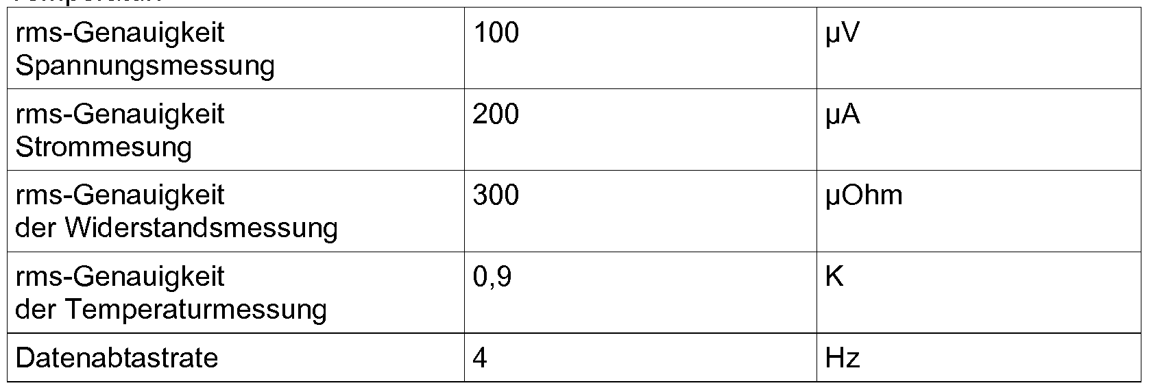
Temperaturregelung
Vor dem eigentlichen Heizlauf wurde jedes Heizelement individuell gegen ein Thermoelement kalibriert. Dabei handelte es sich um eine 1-Punkt-Kalibrierung bei Raumtemperatur. Die Steigung der Widerstandskennlinie des Heizelements wurde in einer vorange- henden Messung ermittelt und danach als Materialkonstante behandelt, die für jedes der eingesetzten Heizelement gültig ist.
Die über das Heizelement gemessene Temperatur diente als Eingangsgröße für einen Regelkreis. Zur Regelung wurde eine Software PID-Regler eingesetzt, der eine Gleichspannungsquelle (Maximal-Spannung: 5 V, Maximal-Strom 10 A) ansteuerte.
Eine Besonderheit des eingesetzten Verfahrens zur Temperaturerfassung und Regelung besteht darin, dass die Basisgrößen für die Temperaturmessung (Strom und Spannung) absolut synchron gemessen werden. Dies ist wichtig, weil in der vorliegenden Anordnung das Heizelement gleichzeitig als Temperatursensor dient und Änderungen des Stromflusses keine Rückwirkungen auf die Widerstandsmessung haben dürfen. Bei nicht nicht synchroner Erfassung von Strom und Spannung, käme es zu großen systematischen Fehlern bei der Widerstands- und damit auch bei der Temperaturmessung. Dies gilt besonders bei schnellen zeitlichen Änderungen der Stellgröße (d.h. der Heizspannung), wie sie für eine effiziente und schnelle Regelung notwendig sind.
Temperaturprogramm für die Schnellaushärtung der Klebstoffe
Das Temperaturprogramm für die Klebstoffaushärtung umfasste eine schnelle lineare Heizrampe, eine isotherme Aushärtephase und das nachfolgende Abkühlen ohne weiteren Energieeintrag durch das Heizelement. Die Parameter für die Aushärtung sind in Tabelle 2 zusammenfasse
Tabelle 2: Tem eratur ro ramme für die Schnellhärtun .

Durchführung der Schnellhärtung
Zur Halterung und elektrischen Kontaktierung wurde die in Beispiel 3 beschriebene Klebvorrichtung eingesetzt. Um zusätzliche Informationen über die Durchwärmung der Fügeteile zu erhalten, wurde ein Thermoelement Typ K auf der Oberfläche der Fügeteile im Bereich der Klebung angebracht.
Ergebnisse (Temperaturverlauf in der Klebfuge und an der Fügeteiloberfläche)
Die Fig. 9 und 10 zeigen die Temperaturverläufe in der Klebfuge und auf der Fügeteiloberfläche bei der Aushärtung der beiden Modell-Klebstoffe.
Fig. 9: Temperatur/Zeit-Diagramm für 5 Aushärtungsläufe des Folienklebstoffs AF 163_2U. Die Solltemperatur für die Aushärtung des Klebstoffs betrug 280 °C.
Hell dargestellte Temperaturkurven wurden über das Heizelement in der Mitte der Klebschicht gemessen, dunkel dargestellte Kurven mit Hilfe eines Thermoelements an der Oberfläche eines Fügeteils.
Fig. 10: Temperatur/Zeit-Diagramm für 4 Aushärtungsläufe des 2-K-Epoxidklebstoffs 3M Scotchweld EC 7256. Die Solltemperatur für die Aushärtung des Klebstoffs betrug 180 °C. Hell dargestellte Temperaturkurven wurden über das Heizelement in der Mitte der Klebschicht gemessen, dunkel dargestellte Kurven mit Hilfe eines Thermoelements an der Oberfläche eines Fügeteils.
Es ist klar zu erkennen, wie schnell das Temperatursignal aus der Klebfuge auf die durch elektrische Widerstandsheizung eingebrachte Energie reagiert. Die Temperatur auf der Fügeteiloberfläche folgt dem mit einer deutlichen Zeitverzögerung. Für eine Regelung schneller Aufheizprozesse ist die direkte Temperaturmessung in der Klebfuge daher ideal. Eine Regelung über die Oberflächentemperatur ist hingegen mit einer deutlichen Totzeit zwischen der Änderung der Heizleistung und der Temperaturantwort verbunden. Für die Schnellhärtung ist eine Regelung, die sich nur auf die Oberflächentemperatur der Fügeteile stützt, daher nicht sinnvoll.
Beim Vergleich der Aushärtungsläufe für die verschiedenen Klebproben zeigt sich, dass das gewünschte Temperaturprofil sehr präzise und reproduzierbar eingehalten wird. Demgegenüber treten in der Öberflächentemperatur deutliche Abweichungen auf, die darauf zurückzuführen sind, dass der Wärmeabfluss an die Umgebung schlecht kontrollierbar ist (er wird zum Beispiel durch die herrschende Luftströmung bestimmt). Dieses Problem ist vor allem bei hohen Härtungstemperaturen relevant, weil hier große Unterschiede zur Umgebungstemperatur bestehen.
Beim langsamen Abkühlen der Proben nähern sich die Temperaturen von Klebfuge und Oberfläche immer weiter an. Dies ist auch so zu erwarten, weil über die Zeit ein Temperaturausgleich in der geklebten Probe stattfindet.
Ergebnisse (Zug-Scher-Prüfung der Klebproben nach schneller Aushärtung)
Beide untersuchte Modellklebstoffe erreichen nach konventioneller Aushärtung im Umluftofen strukturelle Festigkeiten, die sie für den Einsatz im konstruktiven Bereich geeignet machen. Klebstoff 1 erreichte eine Zug-Scher-Festigkeit von 23 MPa, Klebstoff 2 eine Festigkeit von 33 MPa. Im letzteren Fall stellte die Festigkeit des GFK-Substrats den limitierenden Faktor für die Verbundfestigkeit dar (Fig. 1 1 : Verbundfestigkeiten im
Zug-Scher-Versuch für zwei unterschiedliche Klebstoffsysteme nach konventioneller Ofenhärtung bzw. nach elektrischer Schnellhärtung).
Unter den Bedingungen der Schnellhärtung ergaben sich Klebverbindungen mit Festigkeiten, die zwar merklich unterhalb der konventionell gehärteten Proben lagen, die aber mit 1 1 MPa (Klebstoff 1 ) und 17 MPa (Klebstoff 2) für viele strukturelle Aufgaben ausreichend sind.
Die Analyse des Bruchbildes legt nahe, dass der Festigkeitsverlust zumindest zum Teil durch das eingelegte Heizelement verursacht wird. Bei allen Klebungen wurde ein Adhäsionsversagen zur perforierten Edelstahlfolie beobachtet. Hier ist wahrscheinlich noch eine Verbesserung möglich, weil die für die Versuche verwendeten Edelstahlfolien nicht speziell vorbehandelt wurden und Edelstahl ohne Vorbehandlung als schwer zu klebendes Material gilt.
Die Klebproben zeigten trotz der z.T. sehr hohen Aushärtungstemperaturen keinerlei visuell erkennbare Anzeichen von Zersetzung des Klebstoffs oder Fügeteile (Verfärbung oder Blasenbildung). Dies zeigt, dass mit der eingesetzten Methode eine sehr gleichmäßige und kontrollierte Erwärmung der Klebschicht möglich ist.
Zusammenfassung der Ergebnisse
Durch geregelte elektrische Widerstandserwärmung konnten zwei unterschiedliche Modellklebstoffe innerhalb von 70 Sekunden ausgehärtet werden. Die Klebstoffe erreich- ten dabei strukturelle Festigkeiten > 10 MPa. Die Regelung ermöglichte sehr hohe Erwärmungsraten und eine reproduzierbare Einhaltung des vorgegebenen Temperaturprofils. Die Versuche zeigen, das er mit Hilfe der neu entwickelten Elektronik zur Messdatenerfassung möglich ist, das zur Erwärmung der Klebschicht verwendete Heizelement gleichzeitig als präzisen und schnell reagierenden Temperatursensor einzusetzen. Zu- sätzliche Temperatur-Sensoren (z.B. Thermoelemente) können deshalb entfallen. Gegenüber der dem Stand der Technik entsprechenden Temperaturmessung an der Oberfläche der Fügepartner bietet die neue Methode den Vorteil einer wesentlich verkürzten Ansprechzeit. Dies ist die Grundvoraussetzung für eine kontrollierte Schnellhärtung von Klebstoffen.
Claims
1 . Verfahren zum Verbinden zweier Fügeelemente, umfassend die Schritte: a) Bereitstellen der zwei Fügeelemente, b) Bereitstellen eines thermisch aktivierbaren Klebstoffes, c) Bereitstellen eines flächigen Heizelementes d) Anordnen des Heizelements im Klebstoff, e) Anordnen des Heizelementes und des Klebstoffes zwischen den Fügeelementen, f) Erwärmen des Klebstoffes durch Beaufschlagung des Heizelementes mit elektri- scher Leistung unter gleichzeitiger Messung der Temperatur des Klebstoffes, wobei der Umfang der Beaufschlagung des Heizelementes mit elektrischer Leistung abhängig von der gemessenen Temperatur gesteuert wird wobei die Messung der Temperatur des Klebstoffes durch Bestimmung des Widerstandes des Heizelementes erfolgt.
2. Verfahren nach Anspruch 1 , wobei der Widerstand bestimmt wird über Messung der Spannung und Stromstärke, mit einer Zeitdifferenz zwischen Stromstärke-und Spannungsmessung von <10 ms, bevorzugt < 1 ms, weiter bevorzugt <100 is und besonders bevorzugt < 10 [is.
3. Verfahren nach Anspruch 1 oder2, wobei die Steuerung der elektrischen Leistung in Abhängigkeit eines Temperatur - Widerstand - Datensatzes erfolgt, der für das eingesetzte Heizelement material- und geometriespezifische Daten umfasst.
4. Verfahren nach Anspruch 3, wobei die zur Temperaturberechnung benötigten, geometrieabhängigen Kenndaten des Heizelementes über eine automatische Widerstandsmessung, vor oder während der Erwärmung , ermittelt werden.
5. Verfahren nach einem der vorangehenden Ansprüche, wobei die Steuerung der elektrischen Leistung in Abhängigkeit einer Zeit - Temperaturkurve erfolgt.
6. Verfahren nach einem der vorangehenden Ansprüche, wobei die Steuerung der elektrischen Leistung mit einer maximalen Verzögerung von < 1000 ms, bevorzugt < 500 ms, weiter bevorzugt < 250 ms erfolgt.
7. Verfahren nach einem der vorangehenden Ansprüche, wobei der Klebstoff im nicht- aktivierten Zustand fest ist.
8. Verfahren nach einem der Vorangehenden Ansprüche, wobei der Klebstoff im ausgehärteten Zustand ein Duromer ist.
9. Verfahren nach einem der vorangehenden Ansprüche, wobei wenigstens eines der Fügeelemente, bevorzugt beide Fügeelemente ein Kunststoff ist oder aus anderen nicht- metallischen Werkstoffen besteht.
10. Verfahren nach einem der vorangehenden Ansprüche, wobei wenigstens ein Fügeelement ausgewählt ist aus der Gruppe bestehend aus Bolzen, Winkel, Platte, Halter und Beschlag.
1 1. Anordnung, eingerichtet zur Durchführung eines Verfahrens nach einem der Ansprü- che 1 - 10, umfassend
(i) Kontakte zum Kontaktieren eines Heizelementes zur Beaufschlagung mit elektrischer Leistung,
(ii) einen thermisch aktivierbaren Klebstoff, in dem ein flächiges Heizelement angeordnet ist und (iii) eine Steuerungseinheit zur Steuerung der der elektrischen Leistung in Abhängigkeit von der Temperatur des Klebstoffes.
Priority Applications (2)
| Application Number | Priority Date | Filing Date | Title |
|---|---|---|---|
| US16/087,492 US11014310B2 (en) | 2016-03-24 | 2017-03-23 | Method for connecting two joining elements |
| EP17713283.4A EP3433079B1 (de) | 2016-03-24 | 2017-03-23 | Verfahren zum verbinden zweier fügeelemente |
Applications Claiming Priority (2)
| Application Number | Priority Date | Filing Date | Title |
|---|---|---|---|
| DE102016205039.7 | 2016-03-24 | ||
| DE102016205039.7A DE102016205039A1 (de) | 2016-03-24 | 2016-03-24 | Verfahren zum Verbinden zweier Fügeelemente |
Publications (1)
| Publication Number | Publication Date |
|---|---|
| WO2017162829A1 true WO2017162829A1 (de) | 2017-09-28 |
Family
ID=58410342
Family Applications (1)
| Application Number | Title | Priority Date | Filing Date |
|---|---|---|---|
| PCT/EP2017/057003 WO2017162829A1 (de) | 2016-03-24 | 2017-03-23 | Verfahren zum verbinden zweier fügeelemente |
Country Status (4)
| Country | Link |
|---|---|
| US (1) | US11014310B2 (de) |
| EP (1) | EP3433079B1 (de) |
| DE (1) | DE102016205039A1 (de) |
| WO (1) | WO2017162829A1 (de) |
Cited By (1)
| Publication number | Priority date | Publication date | Assignee | Title |
|---|---|---|---|---|
| EP3751248A1 (de) | 2019-06-14 | 2020-12-16 | Thales Management & Services Deutschland GmbH | Schienenüberwachungselement, verfahren zur montage eines schienenüberwachungselements und verfahren zur herstellung eines schienenüberwachungselements |
Families Citing this family (5)
| Publication number | Priority date | Publication date | Assignee | Title |
|---|---|---|---|---|
| CN109803812A (zh) * | 2016-10-07 | 2019-05-24 | 多种材料焊接股份公司 | 活化粘合剂的方法 |
| NL2023804A (en) * | 2018-10-05 | 2020-05-06 | Asml Holding Nv | Method for internal heating of epoxy bonds |
| DE102019214107A1 (de) * | 2019-09-17 | 2021-03-18 | Ford Global Technologies, Llc | Verfahren zur Herstellung von mehrteiligen Kraftfahrzeugteilen mittels Klebeverbindung |
| CN114393844A (zh) * | 2022-01-16 | 2022-04-26 | 中国民航大学 | 一种复合材料二次胶接装置及胶接方法 |
| DE102022131478A1 (de) | 2022-11-29 | 2024-05-29 | Bayerische Motoren Werke Aktiengesellschaft | Verfahren und System zum stoffschlüssigen Verbinden von Bauteilen sowie Fahrzeug |
Citations (7)
| Publication number | Priority date | Publication date | Assignee | Title |
|---|---|---|---|---|
| DE2362247A1 (de) | 1972-12-21 | 1974-06-27 | Centre Rech Metallurgique | Verfahren zur herstellung von erzeugnissen durch kleben |
| EP0067621A2 (de) * | 1981-06-16 | 1982-12-22 | Brintons Limited | Verbinden von Textilmaterial |
| EP0141065B1 (de) | 1983-08-30 | 1987-12-16 | Robert Bosch Gmbh | Verfahren zum Verkleben von Blechen, Vorrichtung zur Durchführung des Verfahrens und Verwendung duroplastischer Kunstharze zum Verkleben von Blechen |
| US5500510A (en) * | 1994-11-02 | 1996-03-19 | Toua Kokyu Tugitevarubu Seizo Co. | Method of automatically controlling the fusion process between thermoplastic articles |
| JPH09109263A (ja) * | 1995-10-19 | 1997-04-28 | Hirata Corp | 電気溶融着装置及びその通電制御方法 |
| WO1999021694A1 (en) * | 1997-10-28 | 1999-05-06 | Lear Corporation | Method of making a part utilizing an electrically conductive material |
| US20030116282A1 (en) | 2001-12-18 | 2003-06-26 | Hutter Charles G. | Adhesive attachment assembly with heat source |
Family Cites Families (10)
| Publication number | Priority date | Publication date | Assignee | Title |
|---|---|---|---|---|
| DE1065052B (de) * | 1957-07-18 | 1959-09-10 | Karl Wanisch Fa Dipl Ing | Elektrisch leitende Verklebung |
| DE2154037A1 (de) * | 1971-10-29 | 1973-05-10 | Josef Fischer Kg Holzwerke | Verfahren zur flaechen- oder punktverklebung und hierfuer geeignete klebeelemente |
| FR2547345B1 (fr) * | 1983-06-10 | 1986-11-14 | Boussois Sa | Vitrage pret a la pose notamment pour automobile |
| DE3505115A1 (de) * | 1985-02-14 | 1986-08-14 | Siemens AG, 1000 Berlin und 8000 München | Elektrisch leitende klebeverbindung |
| US5278382A (en) * | 1990-10-29 | 1994-01-11 | Herfurth Gmbh | Method for the high-frequency heating of dielectric workpieces |
| JPH06278210A (ja) * | 1993-03-29 | 1994-10-04 | Kinugawa Rubber Ind Co Ltd | 樹脂複合体と加硫ゴムとの接合方法 |
| US5750970A (en) * | 1996-07-03 | 1998-05-12 | Ford Global Technologies, Inc. | Method for dielectrically heating an adhesive |
| US6004418A (en) * | 1997-10-28 | 1999-12-21 | Lear Corporation | Method of joining a cover material to a substrate utilizing electrically conductive bonding |
| US6251202B1 (en) * | 1999-05-05 | 2001-06-26 | Patent Holding Company | Method and system for bonding plastic parts together |
| DE102005026815B4 (de) * | 2005-06-09 | 2008-11-27 | Ortwin Prof. Dr.-Ing. Hahn | Klebeverbindung und Herstellungsverfahren hierzu |
-
2016
- 2016-03-24 DE DE102016205039.7A patent/DE102016205039A1/de not_active Withdrawn
-
2017
- 2017-03-23 WO PCT/EP2017/057003 patent/WO2017162829A1/de active Application Filing
- 2017-03-23 US US16/087,492 patent/US11014310B2/en active Active
- 2017-03-23 EP EP17713283.4A patent/EP3433079B1/de active Active
Patent Citations (7)
| Publication number | Priority date | Publication date | Assignee | Title |
|---|---|---|---|---|
| DE2362247A1 (de) | 1972-12-21 | 1974-06-27 | Centre Rech Metallurgique | Verfahren zur herstellung von erzeugnissen durch kleben |
| EP0067621A2 (de) * | 1981-06-16 | 1982-12-22 | Brintons Limited | Verbinden von Textilmaterial |
| EP0141065B1 (de) | 1983-08-30 | 1987-12-16 | Robert Bosch Gmbh | Verfahren zum Verkleben von Blechen, Vorrichtung zur Durchführung des Verfahrens und Verwendung duroplastischer Kunstharze zum Verkleben von Blechen |
| US5500510A (en) * | 1994-11-02 | 1996-03-19 | Toua Kokyu Tugitevarubu Seizo Co. | Method of automatically controlling the fusion process between thermoplastic articles |
| JPH09109263A (ja) * | 1995-10-19 | 1997-04-28 | Hirata Corp | 電気溶融着装置及びその通電制御方法 |
| WO1999021694A1 (en) * | 1997-10-28 | 1999-05-06 | Lear Corporation | Method of making a part utilizing an electrically conductive material |
| US20030116282A1 (en) | 2001-12-18 | 2003-06-26 | Hutter Charles G. | Adhesive attachment assembly with heat source |
Cited By (2)
| Publication number | Priority date | Publication date | Assignee | Title |
|---|---|---|---|---|
| EP3751248A1 (de) | 2019-06-14 | 2020-12-16 | Thales Management & Services Deutschland GmbH | Schienenüberwachungselement, verfahren zur montage eines schienenüberwachungselements und verfahren zur herstellung eines schienenüberwachungselements |
| WO2020249300A1 (de) | 2019-06-14 | 2020-12-17 | Thales Management & Services Deutschland Gmbh | Schienenüberwachungselement, verfahren zur montage eines schienenüberwachungselements und verfahren zur herstellung eines schienenüberwachungselements |
Also Published As
| Publication number | Publication date |
|---|---|
| EP3433079B1 (de) | 2021-08-25 |
| US11014310B2 (en) | 2021-05-25 |
| US20190105847A1 (en) | 2019-04-11 |
| DE102016205039A1 (de) | 2017-09-28 |
| EP3433079A1 (de) | 2019-01-30 |
Similar Documents
| Publication | Publication Date | Title |
|---|---|---|
| EP3433079B1 (de) | Verfahren zum verbinden zweier fügeelemente | |
| DE3801843A1 (de) | Heizvorrichtung | |
| US20220402173A1 (en) | Method and apparatus for curing a composite article | |
| US10252447B2 (en) | Methods and systems for curing materials within cavities | |
| EP3414558B1 (de) | Verfahren zum temperieren einer messprobe | |
| US20170312944A1 (en) | Methods and systems for curing materials within cavities | |
| Souid et al. | Influence of reversion on adhesion in the rubber-to-metal vulcanization-bonding process | |
| EP3433078B1 (de) | Vorrichtung und verfahren zur herstellung oder zum trennen einer verbindung mindestens eines metallischen oder keramischen bauteils und eines aus oder mit einem thermoplastischen polymer gebildeten bauteils | |
| DE102008036332A1 (de) | Verfahren zum Aufbringen eines Reibbelags mittels Siebdruckverfahrens | |
| EP3030914B1 (de) | Thermische abschirmvorrichtung für eine probecard und entsprechende probecardanordnung | |
| US10385905B1 (en) | Bonded hardware rapid cure system | |
| EP2940321B1 (de) | Vorrichtung zum aushärten eines elektrisch leitenden klebstoffes | |
| DE102016117178A1 (de) | Verfahren und Vorrichtung zum Konsolidieren einer Faserpreform | |
| EP2026954B1 (de) | Vorrichtung zur verbesserung der gleichförmigkeit eines tests für innere bindestärke an geklebten plattenprodukten auf biobasis | |
| Smith et al. | Boundary control of embedded heaters for uniform bondline temperatures during composite joining | |
| Smith | Bondline temperature control using carbon fiber embedded resistive heaters | |
| CN102127374A (zh) | 应用dad-40导电胶粘接类产品的返修方法 | |
| EP2548931B1 (de) | Verfahren zum Herstellen einer Klebverbindung mit einem hitzeaktivierbaren Kleber mittels Induktionserwärmung | |
| AT525854A1 (de) | Testsystem für Batteriezellen oder Batteriezellenstapel | |
| DE102022203563A1 (de) | Prüfaufbau | |
| DE102015202415B4 (de) | Klebstoff, Bauteil, Verfahren zur berührungslosen Temperaturmessung des Klebstoffs, Verfahren zur verbesserten Verbindung zweier Bauteile mit dem Klebstoff und Verwendung des Klebstoffs | |
| DE2235558A1 (de) | Verfahren und vorrichtung zum erwaermen von metallteilen zum zwecke ihrer verklebung mit nichtmetallischen werkstoffen | |
| WO2022148770A1 (de) | Heizvorrichtung | |
| DE202004007301U1 (de) | Probenträger für Röntgenbeugungsanalyse mit dem die Probe sowohl beheizt als auch gekühlt werden kann | |
| WO2013132069A1 (de) | Heizelement |
Legal Events
| Date | Code | Title | Description |
|---|---|---|---|
| NENP | Non-entry into the national phase |
Ref country code: DE |
|
| WWE | Wipo information: entry into national phase |
Ref document number: 2017713283 Country of ref document: EP |
|
| ENP | Entry into the national phase |
Ref document number: 2017713283 Country of ref document: EP Effective date: 20181024 |
|
| 121 | Ep: the epo has been informed by wipo that ep was designated in this application |
Ref document number: 17713283 Country of ref document: EP Kind code of ref document: A1 |