WO2017159516A1 - 外圧式中空糸膜モジュール - Google Patents
外圧式中空糸膜モジュール Download PDFInfo
- Publication number
- WO2017159516A1 WO2017159516A1 PCT/JP2017/009355 JP2017009355W WO2017159516A1 WO 2017159516 A1 WO2017159516 A1 WO 2017159516A1 JP 2017009355 W JP2017009355 W JP 2017009355W WO 2017159516 A1 WO2017159516 A1 WO 2017159516A1
- Authority
- WO
- WIPO (PCT)
- Prior art keywords
- hollow fiber
- fiber membrane
- raw water
- bundles
- adhesive
- Prior art date
- Legal status (The legal status is an assumption and is not a legal conclusion. Google has not performed a legal analysis and makes no representation as to the accuracy of the status listed.)
- Ceased
Links
Images


Classifications
-
- B—PERFORMING OPERATIONS; TRANSPORTING
- B01—PHYSICAL OR CHEMICAL PROCESSES OR APPARATUS IN GENERAL
- B01D—SEPARATION
- B01D63/00—Apparatus in general for separation processes using semi-permeable membranes
- B01D63/02—Hollow fibre modules
- B01D63/04—Hollow fibre modules comprising multiple hollow fibre assemblies
- B01D63/043—Hollow fibre modules comprising multiple hollow fibre assemblies with separate tube sheets
-
- B—PERFORMING OPERATIONS; TRANSPORTING
- B01—PHYSICAL OR CHEMICAL PROCESSES OR APPARATUS IN GENERAL
- B01D—SEPARATION
- B01D63/00—Apparatus in general for separation processes using semi-permeable membranes
- B01D63/02—Hollow fibre modules
- B01D63/021—Manufacturing thereof
- B01D63/022—Encapsulating hollow fibres
- B01D63/0223—Encapsulating hollow fibres by fixing the hollow fibres prior to encapsulation
-
- B—PERFORMING OPERATIONS; TRANSPORTING
- B01—PHYSICAL OR CHEMICAL PROCESSES OR APPARATUS IN GENERAL
- B01D—SEPARATION
- B01D63/00—Apparatus in general for separation processes using semi-permeable membranes
- B01D63/02—Hollow fibre modules
- B01D63/021—Manufacturing thereof
- B01D63/0233—Manufacturing thereof forming the bundle
-
- B—PERFORMING OPERATIONS; TRANSPORTING
- B01—PHYSICAL OR CHEMICAL PROCESSES OR APPARATUS IN GENERAL
- B01D—SEPARATION
- B01D63/00—Apparatus in general for separation processes using semi-permeable membranes
- B01D63/02—Hollow fibre modules
- B01D63/024—Hollow fibre modules with a single potted end
-
- B—PERFORMING OPERATIONS; TRANSPORTING
- B01—PHYSICAL OR CHEMICAL PROCESSES OR APPARATUS IN GENERAL
- B01D—SEPARATION
- B01D63/00—Apparatus in general for separation processes using semi-permeable membranes
- B01D63/02—Hollow fibre modules
- B01D63/033—Specific distribution of fibres within one potting or tube-sheet
-
- B—PERFORMING OPERATIONS; TRANSPORTING
- B01—PHYSICAL OR CHEMICAL PROCESSES OR APPARATUS IN GENERAL
- B01D—SEPARATION
- B01D63/00—Apparatus in general for separation processes using semi-permeable membranes
- B01D63/02—Hollow fibre modules
- B01D63/04—Hollow fibre modules comprising multiple hollow fibre assemblies
- B01D63/046—Hollow fibre modules comprising multiple hollow fibre assemblies in separate housings
-
- B—PERFORMING OPERATIONS; TRANSPORTING
- B01—PHYSICAL OR CHEMICAL PROCESSES OR APPARATUS IN GENERAL
- B01D—SEPARATION
- B01D65/00—Accessories or auxiliary operations, in general, for separation processes or apparatus using semi-permeable membranes
- B01D65/08—Prevention of membrane fouling or of concentration polarisation
-
- B—PERFORMING OPERATIONS; TRANSPORTING
- B01—PHYSICAL OR CHEMICAL PROCESSES OR APPARATUS IN GENERAL
- B01D—SEPARATION
- B01D2313/00—Details relating to membrane modules or apparatus
- B01D2313/08—Flow guidance means within the module or the apparatus
-
- B—PERFORMING OPERATIONS; TRANSPORTING
- B01—PHYSICAL OR CHEMICAL PROCESSES OR APPARATUS IN GENERAL
- B01D—SEPARATION
- B01D2313/00—Details relating to membrane modules or apparatus
- B01D2313/21—Specific headers, end caps
Definitions
- the present invention relates to an external pressure type hollow fiber membrane module that can be used for water treatment in various fields.
- the filtration performance deteriorates due to clogging of the membrane or the formation of an adhesion layer on the membrane surface. Fouling may occur. When such fouling occurs, the filtration performance is recovered by washing the membrane by air scrubbing washing or back pressure washing.
- FIG. 6 of Patent Document 1 Japanese Patent No. 4498373 shows a module for a rack-type filtration device.
- One end of the multiple hollow fiber membranes 3a is integrated with an adhesive fixing layer 14 having a through hole 14a.
- raw water is supplied to the supply water inlet 2c, enters the lower ring 13, and then is guided to the outer peripheral surface of the hollow fiber membrane 3a through the through hole 14a (paragraph number 0046).
- gas bubbling the hollow fiber membrane 3a gas is supplied from the gas supply port to the lower ring 13, and the hollow fiber membrane 3a is vibrated through the through hole 14a of the adhesive fixing portion 14 (paragraph number 0047).
- 7 and 8 show the positional relationship between the hollow fiber membrane 3a and the through hole 14a.
- FIG. 1 of Patent Document 2 Japanese Patent No. 3686225 shows a hollow fiber membrane module in which a rectifying pipe 6 is disposed in the vicinity of the center of the hollow fiber membrane bundle 1.
- the liquid to be treated enters from the raw water inlet 7, is filtered by the hollow fiber membrane 1 through the outer periphery of the hollow fiber membrane bundle and the rectifying pipe 6, and goes out of the hollow fiber membrane module through the filtered water outlet 8.
- the air supplied from the air inlet 10 which also serves as a drain outlet is distributed by the air nozzle 5 and released to the hollow fiber membrane 1 (paragraph 0011).
- FIG. 1 of Patent Document 3 Japanese Patent No. 5708619 shows a hollow fiber membrane module 1. Both ends of the hollow fiber membrane 4 are provided with potting portions 5 and 5 ′, and a conical through hole 6 serving as an outlet for the liquid supplied from the outside of the module is formed in the central portion of the potting portion 5.
- potting portions 5 and 5 ′ Both ends of the hollow fiber membrane 4 are provided with potting portions 5 and 5 ′, and a conical through hole 6 serving as an outlet for the liquid supplied from the outside of the module is formed in the central portion of the potting portion 5.
- FIG. 1 of Patent Document 4 Japanese Patent No. 3694535
- the hollow fiber membrane module accommodates a hollow fiber membrane 2 in which a large number of tubes are focused in a module case 1 and an introduction tube 4 having water guide holes 5 inserted into the hollow fiber membrane 2.
- One end of the introduction pipe 4 is fixed by the resin fixing portion 3 and the other end is opened, and is communicated with the raw water passage (paragraph number 0018).
- the raw water introduced from the raw water passage is supplied to the outer peripheral surface of the hollow fiber membrane bundle and simultaneously supplied from the water introduction hole 5 of the water conduit 4 to the inner peripheral surface of the hollow fiber membrane bundle.
- An object of the present invention is to provide an external pressure type hollow fiber membrane module in which fouling is unlikely to occur in the hollow fiber membrane during the filtration operation and the hollow fiber membrane has good cleanability.
- the present invention includes a cylindrical housing in which a cap having a liquid inlet / outlet including a raw water supply port and a permeate discharge port is fixed to each of both end openings, and a plurality of hollow fiber membrane bundles are accommodated in the cylindrical housing.
- a hollow fiber membrane module, The plurality of hollow fiber membrane bundles, The first end side of the raw water supply port side is fixed by an adhesive together with the inner wall surface of the cylindrical housing or the inner wall surface of the cap in a state where the first end surface side of the hollow fiber membrane bundle is closed.
- the fixing portion by the adhesive on the first end face side has a plurality of raw water introduction holes formed penetrating in the thickness direction,
- the plurality of raw water introduction holes are A first group raw water introduction hole formed at a position including a central portion of each of the plurality of hollow fiber membrane bundles, between the plurality of hollow fiber membrane bundles, and the plurality of hollow fiber membrane bundles and the cylindrical housing
- An external pressure type hollow fiber membrane module having a second group raw water introduction hole formed between the inner wall surface and the inner wall surface is provided.
- the raw water is supplied to both the inside and the outside of the hollow fiber membrane bundle, so that the uneven flow of the raw water is reduced. For this reason, it becomes difficult to form a deposit layer derived from suspended solids on the surface of the hollow fiber membrane, and clogging is less likely to occur, so that fouling is less likely to occur.
- FIG. 1 is a cross-sectional view in the major axis direction of an external pressure type hollow fiber membrane module of the present invention.
- (A) is the elements on larger scale of the 1st edge part side of FIG. 1
- (b) is the elements on larger scale of the 2nd edge part side of FIG.
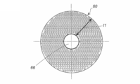
- FIG. 4 is an enlarged view of a bundle of hollow fiber membranes in FIG. 3.
- a plurality of hollow fiber membrane bundles 60 are accommodated in a cylindrical housing 10.
- the cross-sectional shape of the cylindrical housing 10 in the width direction can be a circle, a polygon (preferably a polygon close to a circle), or the like.
- the material of the cylindrical housing 10 can be metal, synthetic resin, or the like.
- the size of the cylindrical housing 10 (the size of the inner volume) can be determined according to the total number of hollow fiber membrane bundles used corresponding to the filtration performance.
- a first end side cap 20 is attached to the first end 10a side of the cylindrical housing 10 from the outside.
- the first end side cap 20 is preferably made of the same material as the cylindrical housing 10.
- the first end portion side cap 20 is composed of a combination of a first a cap portion 21 and a second a cap portion 30 having a raw water supply port (also serving as a counter pressure washing water outlet) 22.
- the first a cap portion 21 and the second a cap portion 30 may be a single unit in which they are integrated.
- the 1a cap portion 21 includes a raw water supply port (1a small diameter portion) 22 and a 1a annular large diameter portion 23 having a larger outer diameter than the raw water supply port 22 on the opposite side of the raw water supply port 22 in the axial X direction. Furthermore, between the raw
- the size of the first a-annular large-diameter portion 23 is approximately the same as the outer diameter of the second-a cap portion 30 (second-a thin portion 33).
- the inner surface of the 1a annular large diameter part 23 has an inner thread part.
- An annular groove is formed in the annular end surface inside the 1a annular flat surface portion 25, and an O-ring 26 is fitted therein.
- the second a cap portion 30 has such a size that the second end portion 30b side can be fitted into the first end portion 10a side of the cylindrical housing 10 from the outside, and the opposite first end portion 30a side is a hollow fiber membrane bundle. It is a cylindrical thing of the magnitude
- the second a cap portion 30 has a second a annular step surface 31 on the inner surface side, a second a thick portion 32 having a small inner diameter on the second end portion 30b side from the second a annular step surface 31, and a second a.
- the 2a thin part 33 has a large internal diameter by the side of the 1st end part 30a from the cyclic
- the outer surface of the 2a thick portion 32 is an inclined surface, but it may be a flat surface.
- the outer surface of the second-a thin portion 33 has an outer screw portion that can be screwed together with the inner screw portion of the first-a annular large-diameter portion 23.
- the second a cap portion 30 may be integrally formed with the first end portion 10a side of the cylindrical housing 10.
- the 1a cap part 21 is a separate member.
- the second a cap portion 30 is fitted on the second end 30b side from the outside to the first end portion 10a side of the cylindrical housing 10, and the first end portion 30a side is the first end face 60a (first fixing) of the hollow fiber membrane bundle 60.
- Layer 61) is connected in a state fitted from the outside.
- the connection between the first end portion 10a of the cylindrical housing 10 and the cylindrical second a cap portion 30 can be applied by a method such as screwing, bonding with an adhesive, welding, or the like according to the respective materials.
- the first a cap portion 21 and the second a cap portion 30 are connected by screwing together the inner screw portion of the annular large diameter portion 23 of the first a cap portion 21 and the outer screw portion of the second a thin portion 33 of the second a cap portion 30. It is fixed.
- a second end side cap 40 is attached to the second end 10b side of the cylindrical housing 10 from the outside.
- the second end side cap 40 is preferably made of the same material as the cylindrical housing 10.
- the second end side cap 40 is composed of a combination of a 1b cap part 41 having a permeate outlet 42 and a second b cap part 50 having a concentrated water outlet 55.
- the first b cap portion 41 and the second b cap portion 50 may be a single unit in which they are integrated.
- the first b cap portion 41 includes a permeate outlet (first b small diameter portion) 42 and a first b annular large diameter portion 43 having a larger outer diameter than the permeate outlet 42 on the opposite side of the permeate outlet 42 in the axis X direction.
- the permeate outlet (first b small diameter part) 42 and the second b annular large diameter part 43 the 1b annular inclined surface part in order from the permeate outlet 42 side to the 1b annular large diameter part 43 side. 44 and a 1b annular flat surface portion 45.
- the size of the 1b annular large-diameter portion 43 is approximately the same as the outer diameter of the second b cap portion 50 (second b thin portion 53).
- the inner surface of the 1b annular large-diameter portion 43 has an inner screw portion.
- An annular groove is formed in the annular end surface inside the 1b annular flat surface portion 45, and an O-ring 46 is fitted therein.
- the second b cap portion 50 has a size such that the second end portion 50b side can be fitted into the second end portion 10b side of the cylindrical housing 10 from the outside, and the opposite second end portion first end portion 50a side is fitted.
- the hollow fiber membrane bundle 60 has a cylindrical shape having a size that can be fitted into the second end face 60b (second fixed layer 62) from the outside.
- the second b cap portion 50 has a second b annular step surface 51 on the inner surface side, a second b thick portion 52 having a small inner diameter on the second end portion 50b side from the second b annular step surface 51, and a second b.
- the 2b thin part 53 has a big internal diameter by the side of the 1b cap part 41 from the cyclic
- the outer surface of the second b thick portion 52 is an inclined surface, but it may be a flat surface.
- the outer surface of the second b thin portion 53 has an outer screw portion that can be screwed together with the inner screw portion of the first b annular large diameter portion 43.
- the second b cap portion 50 of the second end portion side cap 40 may be integrally formed with the second end portion 10b side of the cylindrical housing 10.
- the first b cap portion 41 is a separate member.
- the second b cap portion 50 is fitted from the outside to the second end portion 10b side of the cylindrical housing 10 on the second end portion 50b side, and the second end surface 60b (second fixed side) of the hollow fiber membrane bundle 60 on the first end portion 50a side.
- Layer 62 is connected in a state of being fitted from the outside.
- methods such as screwing, bonding with an adhesive, welding, and the like can be applied according to the respective materials.
- the first b cap portion 41 and the second b cap portion 50 are formed by screwing together the inner screw portion of the first b annular large-diameter portion 43 of the first b cap portion 41 and the outer screw portion of the second b thin portion 53 of the second b cap portion 50.
- the connection at is fixed.
- the plurality of hollow fiber membrane bundles 60 are bundles of hundreds to thousands of known hollow fiber membranes.
- the hollow fiber membrane is a known one, and a hydrophilic membrane (cellulosic membrane such as cellulose acetate) or a hydrophobic membrane having an outer diameter of preferably 1 to 3 mm, more preferably 1.3 to 1.6 mm is used. Can do.
- a hydrophilic film that is less prone to fouling is preferable, and in particular, a cellulose ester film such as cellulose acetate is preferably used.
- the plurality of hollow fiber membrane bundles 60 has a first end side cap 20 (second a cap portion 30) on the first end surface 60a side on the first end portion 10a side (first end side cap 20 side) of the cylindrical housing 10. ) And the inner wall surface thereof are fixed in a state of being integrated by a known adhesive (potting agent) (first fixing layer 61).
- the plurality of hollow fiber membrane bundles 60 has a second end side cap 40 (second b cap portion 50) on the second end surface 60b side on the second end portion 10b side (second end side cap 40 side) of the cylindrical housing 10.
- potting agent second fixing layer 62.
- a known adhesive (potting agent) an adhesive made of urethane resin, epoxy resin or the like described in paragraph No. 0027 of Patent Document 1 can be used.
- the first end face 60a side of the plurality of hollow fiber membrane bundles 60 is closed with an adhesive and is not opened.
- the length of the first fixed layer 61 in the major axis X direction is approximately the same as the length of the second fixed layer 62 in the major axis X direction.
- the second end face 60b side of the plurality of hollow fiber membrane bundles 60 is not closed with an adhesive but is opened.
- the length of the second fixed layer 62 in the major axis X direction is a range from the second end surface 60 b of the hollow fiber membrane bundle 60 to a position not in contact with the concentrated water outlet 55.
- the second b cap portion 50 of the second end side cap 40 includes a second b thick portion 52, a second b annular step surface 51, and a second b thin portion 53, and the second b annular step surface 51 and second b thin wall portion.
- a concentrated water outlet 55 is formed between the portions 53. For this reason, between the concentrated water outlet 55 and the hollow fiber membrane bundle 60 facing the concentrated water outlet 55, the difference in thickness between the 2b thick portion (small inner diameter) 52 and the second b thin portion (large inner diameter) 53.
- An annular space 56 having an interval corresponding to (difference in inner diameter) is formed. Since the concentrated water outlet 55 faces the annular space 56, the concentrated water is discharged smoothly.
- the first fixed layer 61 has a plurality of raw water introduction holes 65 formed so as to penetrate in the thickness direction.
- the plurality of raw water introduction holes 65 are formed so as to penetrate the first fixing layer 61, and the leading ends of the introduction holes reach the inside of the hollow fiber membrane bundle 60 that is not fixed with an adhesive. May be.
- the raw water introduction holes 65 are formed at positions that do not face the first group raw water introduction holes 66 formed at positions including the central portions of the plurality of hollow fiber membrane bundles 60 and the plurality of hollow fiber membrane bundles 60 in the length direction.
- the second group raw water introduction hole 67 is formed.
- the number of first group raw water introduction holes 66 is the same as the number of hollow fiber membrane bundles 60.
- the second fixed layer 62 does not have the raw water introduction hole 65 described above.
- the outer diameter (diameter) of the hollow fiber membrane bundle 60 is preferably 30 to 70 mm, and more preferably 40 to 60 mm.
- the thickness of the hollow fiber membrane bundle 60 (the distance from the inner peripheral surface of the first group raw water introduction hole 66 to the outer peripheral surface of the hollow fiber membrane bundle 60) (t1 in FIG. 4) is preferably 12 to 30 mm, more preferably 15 to 25 mm. preferable.
- the opening diameter of the first group raw water introduction hole 66 is not particularly limited, but is preferably in the range of 20 to 40% of the diameter of the hollow fiber membrane bundle 60.
- the number of the second group raw water introduction holes 67 is not particularly limited, but is preferably equal to or more than the number of the first group raw water introduction holes 66.
- the opening diameter of the second group raw water introduction hole 67 is not particularly limited.
- hollow fiber membrane bundles 60 are accommodated in the cylindrical housing 10, it is preferable that three or more hollow fiber membranes 60 are accommodated.
- three or more hollow fiber membrane bundles 60 are accommodated, they are arranged so as to be line symmetric with respect to a straight line passing through the center of the radial cross section of the first fixed layer 61 when viewed from the first end face 60a side. It is preferable that
- hollow fiber membrane bundles 60 are accommodated in the cylindrical housing 10, it is preferable that four or more bundles of hollow fiber membranes 60 are accommodated.
- four or more hollow fiber membrane bundles 60 are accommodated, they are arranged in line symmetry as described above, and when viewed from the first end face 60a side, the center of the radial cross section of the first fixed layer 61 is used as a reference. May be arranged so as to be point-symmetric.
- the hollow fiber membrane bundles 60 having an odd number of bundles of 5 or more are arranged in a ring shape, they are line symmetric but not point symmetric. However, as shown in FIG. 3, even if there are five or more odd-numbered bundles, if one bundle is arranged at the center and the remaining even-numbered bundles are arranged in an annular shape around the bundle, it becomes line symmetric and point symmetric. Also become.
- all the membranes other than the central hollow fiber membrane bundle disposed at the center of the cross section in the radial direction of the fixing portion by the adhesive when viewed from the first end face side The bundles preferably have the same dimensions (outer diameter and thickness t1), but there may be a difference of about ⁇ 5%.
- ⁇ 100) is preferably 5 to 20%, more preferably 10 to 15%.
- the ratio (A3 / A4) of the opening area (A3) of the first group raw water introduction hole 66 and the opening area (A4) of the second group raw water introduction hole 67 is 0.4 to 0.6 is preferable, and 0.5 to 0.56 is more preferable.
- the hollow fiber membrane module 1 of the present invention includes a porous tube or a net-like pipe for introducing raw water, a partition plate for internal arrangement, a reinforcing rod-like body (preferably made of synthetic resin), etc., as necessary. Can be used.
- the hollow fiber membrane module 1 having the layer 62 can be manufactured by the following method.
- a first container having a bottom surface and a peripheral wall portion, and a plurality of rod-shaped molded bodies are suspended from the bottom surface at intervals, and a second container that is the same except that the rod-shaped molded body is not provided.
- the number, the forming position, the outer diameter, and the length of the rod-shaped molded body coincide with the number, the forming position, the inner diameter, and the depth of the plurality of raw water introduction holes 65.
- the length of the rod-shaped molded body is equal to or longer than the length of the raw water introduction hole 65.
- the second a cap 30 of the first end cap 20 and the second b cap 50 of the second end cap 40 is arranged inside the connected ones.
- the length of the hollow membrane bundle 60 is adjusted in consideration of the subsequent cutting step.
- the first container is attached to the second a cap portion 30 side of the first end side cap 20, and the second container is attached to the second b cap portion 50 side of the second end side cap 40.
- the rod-shaped molded body at the bottom of the first container is inserted into a position corresponding to the first group raw water introduction hole 66 and the second group raw water introduction hole 67 in FIG. Yes.
- an adhesive (potting agent) is poured into the first container and the second container by an adhesion method including a known centrifugal adhesion method, and then solidified.
- an adhesion method including a known centrifugal adhesion method
- the centrifugal bonding method and the stationary bonding method described in Paragraph No. 21 of Patent Document 1 the centrifugal bonding method and the stationary bonding method described in Paragraph No. 21 of Patent Document 1, the Paragraph No. 11 of Patent Document 2, and the multistage potting method described in Paragraph No. 11 of Patent Document 3 are applied. can do.
- the second a cap part 30 side of the first end part side cap 20 is in the state shown in FIG. 3, and the first end face 60a of the hollow fiber membrane bundle 60 is Blocked with adhesive. Since the second end surface 60b of the hollow fiber membrane bundle 60 on the second b cap portion 50 side of the second end portion side cap 40 is closed with an adhesive, the required length is cut and opened. In this way, the first fixed layer 61 and the second fixed layer 62 are formed.
- the first a cap portion 21 is connected to the second a cap portion 30 of the first end side cap 20
- the first b cap portion 41 is connected to the second b cap portion 50 of the second end side cap 40
- the hollow fiber membrane module 1 can be obtained.
- the hollow fiber membrane module 1 of the present invention preferably has a membrane area (effective membrane area) of 10 m 2 or more, more preferably a membrane area (effective membrane area) of 30 to 45 m 2 .
- the filtration operation method of the hollow fiber membrane module 1 of the present invention will be described.
- the hollow fiber membrane module 1 the 1st end part 10a side of the cylindrical housing 10 is in the state shown in FIG.
- the hollow fiber membrane module 1 can be used either vertically or horizontally. However, even when the hollow fiber membrane module 1 is used vertically, the hollow fiber membrane bundle 60 separated from the first fixed layer 61 and the second fixed layer 62 is used. It is conceivable that the central part of the fiber is bent and the adjacent hollow fiber membrane bundles 60 are in contact with each other.
- the first group raw water introduction hole 66 and the second group raw water introduction hole 67 are formed in the first fixed layer 61, the first group raw water introduction hole 66 and the second group raw water introduction hole 67 The raw water is easy to flow in the extending direction of the long axis X direction.
- the raw water is filtered while being supplied to and around the center of the hollow fiber membrane bundle 60, so that the bias of the raw water flow is reduced. It is also difficult to form a deposit layer derived from the above, clogging is difficult to occur, and fouling is difficult to occur.
- Example 1 of the invention of Patent Document 1 backwashing and gas bubbling are performed every 28.5 minutes of filtration operation (paragraph 0056), and in the embodiment of the invention of Patent Document 2 (paragraph number 0019), filtration is performed.
- air scrubbing cleaning is performed once every 30 minutes of operation, in the present invention, air scrubbing can be made unnecessary, or the number of times can be reduced when it is performed. If the number of times of air scrubbing is increased, there is a risk of oscillating hollow fiber membrane bundles repeatedly contacting each other, but the present invention can reduce the number of times even when performing air scrubbing, As mentioned above, the film is hardly damaged.
- the reverse pressure cleaning is performed by press-fitting reverse pressure cleaning water to which a chemical is added as necessary from the permeate outlet 42 side (in some cases, from the concentrated water outlet 55).
- the reverse pressure washing wastewater passes between the hollow fiber membrane bundles 60 and is discharged from the raw water supply port 22 that also serves as the reverse pressure washing water outlet.
- the first group raw water introduction hole 66 and the second group raw water introduction hole 67 are formed in the first fixed layer 61, the long axes of the first group raw water introduction hole 66 and the second group raw water introduction hole 67 are formed. Since the raw water is easy to flow in the extending direction of the X direction, the backwash water is easily discharged.
- Example 1 A filtration operation was carried out using the vertical-type hollow fiber membrane module 1 provided with the cylindrical housing shown in FIG. 1, two caps 20 and 40 on both ends, a first annular holder 30 and a second annular holder 50. Both ends of the hollow fiber membrane bundle were fixed with urethane resin adhesive.
- Tubular housing made of vinyl chloride, outer diameter 17cm, inner diameter 13cm (Hollow fiber membrane bundle) Cellulose acetate hollow fiber membrane Number of hollow fiber membrane bundles: 7 bundles Hollow fiber membrane bundle outer diameter: 5 cm Hollow fiber membrane bundle thickness (t1): 2 cm (First fixed layer 61) 10.
- the drive pump was driven to feed the river water in the raw water tank, which was supplied from the raw water supply port 22 of the hollow fiber membrane module 1 to start filtration.
- the raw water in the raw water tank was supplied from the raw water supply port 22 through a pump and a raw water line, and the entire amount was filtered. Concentrated water is not generated due to the total amount filtration operation. From the permeate outlet 42, 1.5 L / sec of permeate was sent to the permeate tank. The filtration operation was continued for 120 hours, but no deposits were observed on the film surface, and no fouling occurred.
- the hollow fiber membrane module of the present invention can be used in water purification plant facilities, sewage treatment facilities, seawater desalination facilities, and the like.
- Hollow fiber membrane module 10 Tubular housing 20 1st edge part side cap 21 1a cap part 22 Raw water supply port (small diameter part) 23 Large diameter part 30 2a cap part 40 2nd end side cap 41 1b cap part 50 2b cap part 56 annular space 60 hollow fiber membrane bundle 65 raw water introduction hole 65 66 Group 1 raw water introduction hole 67 Group 2 raw water introduction hole
Landscapes
- Chemical & Material Sciences (AREA)
- Chemical Kinetics & Catalysis (AREA)
- Engineering & Computer Science (AREA)
- Manufacturing & Machinery (AREA)
- Separation Using Semi-Permeable Membranes (AREA)
Abstract
濾過運転時において中空糸膜にファウリングが起こりにくく、中空糸膜の洗浄性も良い中空糸膜モジュールを提供すること。 複数の中空糸膜束60の第1端部側と第2端部側が筒状ハウジング10の内壁面またはキャップの内壁面と共に接着剤により固定されている。第1端部側の接着剤による固定部が、厚さ方向に貫通して形成された複数の原水導入孔65を有している。複数の原水導入孔65が、複数の中空糸膜束60のそれぞれの中心部を含む位置に形成された第1群原水導入孔66と、複数の中空糸膜束60同士の間および複数の中空糸膜束60と筒状ハウジング10の内壁面との間に形成されている第2群原水導入孔67を有しているものである、外圧式中空糸膜モジュール。
Description
本発明は、各種分野における水処理用途に使用できる外圧式中空糸膜モジュールに関する。
背景技術
背景技術
多数本の中空糸膜が収容されている中空糸膜モジュールを使用して濾過運転を継続したとき、膜が目詰まりしたり、膜面に付着層が形成されたりすることで、濾過性能が低下するファウリングが生じることがある。このようなファウリングが生じた場合には、エアースクラビング洗浄をしたり、逆圧洗浄をしたりして膜を洗浄することで濾過性能を回復させている。
特許文献1(特許第4498373号公報)の図6には、ラック型濾過装置用モジュールが示されている。多数本の中空糸膜3aの一方の端部は、貫通穴14aを有する接着固定層14で一体化されている。濾過運転時には、原水は供給水入口2cに供給され、下部リング13内に入ったあと、貫通穴14aを通って中空糸膜3aの外周面に導かれる(段落番号0046)。中空糸膜3aをガスバブリングするときは、ガス供給口から下部リング13にガスを供給して、接着固定部14の貫通穴14aを通過させて中空糸膜3aを振動させる(段落番号0047)。図7、図8には、中空糸膜3aと貫通穴14aの位置関係が示されている。
特許文献2(特許第3686225号公報)の図1には、中空糸膜束1の中心近傍に整流管6が配置された中空糸膜モジュールが示されている。濾過運転時には、被処理液が原水入口7から入り、中空糸膜束外周および整流管6を通って中空糸膜1により濾過され、濾過水出口8を通って中空糸膜モジュールの外に出る。エアースクラビング時には、ドレン抜き口を兼ねるエアー導入口10から供給されたエアーがエアーノズル5で分配され、中空糸膜1に対して放出される(段落番号0011)。
特許文献3(特許第5708619号公報)の図1には、中空糸膜モジュール1が示されている。中空糸膜4の両端部はポッティング部5、5'が備えられており、ポッティング部5の中央部分には、モジュール外部から供給された液体の流出口となる円錐形貫通穴6が形成されている(段落番号0011、0013)。前記円錐形貫通穴6を有していることによって、中空糸膜の位置にかかわらず収容されている全ての中空糸膜を有効に利用することができると記載されている(段落番号0014)。
特許文献4(特許第3694535号公報)の図1には、中空糸膜モジュールが示されている。中空糸膜モジュールには、モジュールケース1内に多数本が集束された中空糸膜2と、中空糸膜2の内部に挿入された導水穴5を有する導入管4が収容されている。導入管4は、一端が樹脂固定部3で固定され、他端は開放されており、原水通水路に連通されている(段落番号0018)。濾過運転時、原水通水路から導入された原水は、中空糸膜束の外周面に供給されると同時に、導水管4の導水穴5から中空糸膜束の内周面に供給される。このようにして、原水が中空糸膜束の外周面と内周面の両面から入るため、中空糸膜と原水との接触面積が大きくなり、被濾過物の堆積被覆による中空糸膜の濾過効率の低下を低減できると記載されている(段落番号0019)。
発明の概要
発明の概要
本発明は、濾過運転時において中空糸膜にファウリングが起こりにくく、中空糸膜の洗浄性も良い外圧式中空糸膜モジュールを提供することを課題とする。
本発明は、両端開口部のそれぞれに原水供給口と透過水排出口を含む液出入り口を有するキャップが固定された筒状ハウジングと、前記筒状ハウジング内に複数の中空糸膜束が収容された中空糸膜モジュールであって、
前記複数の中空糸膜束が、
原水供給口側の第1端部側が、前記中空糸膜束の第1端面側が閉塞された状態にて、前記筒状ハウジングの内壁面または前記キャップの内壁面と共に接着剤により固定されており、
前記第1端面側とは軸方向に反対側である透過水出口側の第2端面側が、前記中空糸膜束の第2端面側が開口された状態にて、前記筒状ハウジングの内壁面または前記キャップの内壁面と共に接着剤により固定されており、
前記第1端面側の接着剤による固定部が、厚さ方向に貫通して形成された複数の原水導入孔を有しているものであり、
前記複数の原水導入孔が、
前記複数の中空糸膜束のそれぞれの中心部を含む位置に形成された第1群原水導入孔と、前記複数の中空糸膜束同士の間および前記複数の中空糸膜束と前記筒状ハウジングの内壁面との間に形成されている第2群原水導入孔を有しているものである、外圧式中空糸膜モジュールを提供する。
前記複数の中空糸膜束が、
原水供給口側の第1端部側が、前記中空糸膜束の第1端面側が閉塞された状態にて、前記筒状ハウジングの内壁面または前記キャップの内壁面と共に接着剤により固定されており、
前記第1端面側とは軸方向に反対側である透過水出口側の第2端面側が、前記中空糸膜束の第2端面側が開口された状態にて、前記筒状ハウジングの内壁面または前記キャップの内壁面と共に接着剤により固定されており、
前記第1端面側の接着剤による固定部が、厚さ方向に貫通して形成された複数の原水導入孔を有しているものであり、
前記複数の原水導入孔が、
前記複数の中空糸膜束のそれぞれの中心部を含む位置に形成された第1群原水導入孔と、前記複数の中空糸膜束同士の間および前記複数の中空糸膜束と前記筒状ハウジングの内壁面との間に形成されている第2群原水導入孔を有しているものである、外圧式中空糸膜モジュールを提供する。
本発明の外圧式中空糸膜モジュールは、中空糸膜束の内部と外部の両方に原水が供給されるため、原水の流れの偏りが小さくなる。このため、中空糸膜面に懸濁質に由来する堆積物層が形成され難くなり、目詰まりも生じ難くなることから、ファウリングも生じ難くなる。
発明を実施するための形態
図1に示す外圧式中空糸膜モジュール1は、筒状ハウジング10内に複数の中空糸膜束60が収容されている。筒状ハウジング10の幅方向の断面形状は、円形、多角形(好ましくは円形に近い多角形)などにすることができる。筒状ハウジング10の材質は、金属、合成樹脂などにすることができる。筒状ハウジングの10の大きさ(内容量の大きさ)は、濾過性能に対応して使用する中空糸膜束の合計本数などに応じて決めることができる。
図1に示す外圧式中空糸膜モジュール1は、筒状ハウジング10内に複数の中空糸膜束60が収容されている。筒状ハウジング10の幅方向の断面形状は、円形、多角形(好ましくは円形に近い多角形)などにすることができる。筒状ハウジング10の材質は、金属、合成樹脂などにすることができる。筒状ハウジングの10の大きさ(内容量の大きさ)は、濾過性能に対応して使用する中空糸膜束の合計本数などに応じて決めることができる。
筒状ハウジング10の第1端部10a側には、第1端部側キャップ20が外側から取り付けられている。第1端部側キャップ20は、筒状ハウジング10と同じ材質からなるものが好ましい。
第1端部側キャップ20は、原水供給口(逆圧洗浄水出口を兼ねる)22を有している第1aキャップ部21と第2aキャップ部30の組み合わせからなるものである。第1aキャップ部21と第2aキャップ部30は、それらが一体になった一つのものでもよい。
第1aキャップ部21は、原水供給口(第1a小径部)22と、原水供給口22の軸X方向反対側にある原水供給口22よりも大きな外径を有する第1a環状大径部23を有しており、さらに原水供給口22と第1a環状大径部23の間には、原水供給口22側から第1a環状大径部23側に順に第1a環状傾斜面部24と第1a環状平面部25を有しているものである。第1a環状大径部23の大きさは、第2aキャップ部30(第2a薄肉部33)の外径と同程度の大きさになっている。第1a環状大径部23の内表面は内側ねじ部を有している。第1a環状平面部25の内側の環状端面には環状溝が形成され、Oリング26が嵌め込まれている。
第2aキャップ部30は、第2端部30b側が筒状ハウジング10の第1端部10a側に外側から嵌め込むことができる大きさであり、反対側の第1端部30a側が中空糸膜束60の第1端面60a(第1固定層61)に外側から嵌め込むことができる大きさの筒状のものである。第2aキャップ部30は、内表面側に第2a環状段差面31を有しており、第2a環状段差面31から第2端部30b側の内径の小さい第2a厚肉部32と、第2a環状段差面31から第1端部30a側の内径の大きな第2a薄肉部33を有している(第2a厚肉部32の厚み>第2a薄肉部33の厚み)。図1、図2では、第2a厚肉部32の外表面が傾斜面になっているが、平坦面であってもよい。第2a薄肉部33の外表面は、第1a環状大径部23の内側ねじ部とねじ合わせることができる外側ねじ部を有している。
第2aキャップ部30は、筒状ハウジング10の第1端部10a側と一体成形されていてもよい。第2aキャップ部30と筒状ハウジング10が一体成形されているときは、第1aキャップ部21は別部材である。
第2aキャップ部30は、第2端部30b側が筒状ハウジング10の第1端部10a側に外側から嵌め込まれ、第1端部30a側が中空糸膜束60の第1端面60a(第1固定層61)に外側から嵌め込まれた状態で接続されている。筒状ハウジング10の第1端部10aと筒状の第2aキャップ部30の接続は、それぞれの材質に応じて、ねじ合わせ、接着剤による接着、溶接などの方法を適用することができる。
第1aキャップ部21と第2aキャップ部30は、第1aキャップ部21の環状大径部23の内側ねじ部と第2aキャップ部30の第2a薄肉部33の外側ねじ部をねじ合わせることで接続固定されている。
筒状ハウジング10の第2端部10b側は、第2端部側キャップ40が外側から取り付けられている。第2端部側キャップ40は、筒状ハウジング10と同じ材質からなるものが好ましい。
第2端部側キャップ40は、透過水出口42を有している第1bキャップ部41と、濃縮水出口55を有している第2bキャップ部50の組み合わせからなるものである。第1bキャップ部41と第2bキャップ部50は、それらが一体になった一つのものでもよい。
第1bキャップ部41は、透過水出口(第1b小径部)42と、透過水出口42の軸X方向反対側にある透過水出口42よりも大きな外径を有する第1b環状大径部43を有しており、さらに透過水出口(第1b小径部)42と第2b環状大径部43の間には、透過水出口42側から第1b環状大径部43側に順に第1b環状傾斜面部44と第1b環状平面部45を有しているものである。第1b環状大径部43の大きさは、第2bキャップ部50(第2b薄肉部53)の外径と同程度の大きになっている。第1b環状大径部43の内表面は内側ねじ部を有している。第1b環状平面部45の内側の環状端面には環状溝が形成され、Oリング46が嵌め込まれている。
第2bキャップ部50は、第2端部50b側が筒状ハウジング10の第2端部10b側に外側から嵌め込むことができる大きさであり、反対側の第2端部第1端部50a側が中空糸膜束60の第2端面60b(第2固定層62)に外側から嵌め込むことができる大きさの筒状のものである。第2bキャップ部50は、内表面側に第2b環状段差面51を有しており、第2b環状段差面51から第2端部50b側の内径の小さい第2b厚肉部52と、第2b環状段差面51から第1bキャップ部41側の内径の大きな第2b薄肉部53を有している(第2b厚肉部52の厚み>第2b薄肉部53の厚み)。図1、図2では、第2b厚肉部52の外表面が傾斜面になっているが、平坦面であってもよい。第2b薄肉部53の外表面は、第1b環状大径部43の内側ねじ部とねじ合わせることができる外側ねじ部を有している。
第2端部側キャップ40の第2bキャップ部50は、筒状ハウジング10の第2端部10b側と一体成形されていてもよい。第2bキャップ部50と筒状ハウジング10が一体成形されているときは、第1bキャップ部41は別部材である。
第2bキャップ部50は、第2端部50b側が筒状ハウジング10の第2端部10b側に外側から嵌め込まれ、第1端部50a側が中空糸膜束60の第2端面60b(第2固定層62)に外側から嵌め込まれた状態で接続されている。筒状ハウジング10の第2端部10bと筒状の第2bキャップ部50の接続は、それぞれの材質に応じて、ねじ合わせ、接着剤による接着、溶接などの方法を適用することができる。
第1bキャップ部41と第2bキャップ部50は、第1bキャップ部41の第1b環状大径部43の内側ねじ部と第2bキャップ部50の第2b薄肉部53の外側ねじ部をねじ合わせることで接続固定されている。
複数の中空糸膜束60は、それぞれが数百~数千本の公知の中空糸膜が束ねられたものである。中空糸膜は公知のものであり、外径が好ましくは1~3mm、より好ましくは1.3~1.6mmの親水性膜(酢酸セルロースなどのセルロース系膜)または疎水性膜を使用することができる。本発明の課題を解決するには、ファウリングが生じにくい親水性膜が好ましく、特に酢酸セルロースなどのセルロースエステル系膜の使用が好ましい。
複数の中空糸膜束60は、筒状ハウジング10の第1端部10a側(第1端部側キャップ20側)の第1端面60a側が、第1端部側キャップ20(第2aキャップ部30)の内壁面と共に公知の接着剤(ポッティング剤)により一体化された状態で固定されている(第1固定層61)。複数の中空糸膜束60は、筒状ハウジング10の第2端部10b側(第2端部側キャップ40側)の第2端面60b側が、第2端部側キャップ40(第2bキャップ部50)の内壁面と共に公知の接着剤(ポッティング剤)により一体化された状態で固定されている(第2固定層62)。公知の接着剤(ポッティング剤)としては、特許文献1の段落番号0027に記載されているウレタン樹脂、エポキシ樹脂などからなるものを使用することができる。
複数の中空糸膜束60の第1端面60a側は、接着剤で閉塞され開口されていない。第1固定層61の長軸X方向の長さは第2固定層62の長軸X方向の長さと同程度である。複数の中空糸膜束60の第2端面60b側は、接着剤で閉塞されておらず開口されている。第2固定層62の長軸X方向の長さは、中空糸膜束60の第2端面60bから、濃縮水出口55に接しない位置までの範囲である。
第2端部側キャップ40の第2bキャップ部50は、第2b厚肉部52、第2b環状段差面51、第2b薄肉部53を有しており、第2b環状段差面51、第2b薄肉部53の間に濃縮水出口55が形成されている。このため、濃縮水出口55と、濃縮水出口55に対向する中空糸膜束60の間には、第2b厚肉部(内径小)52と第2b薄肉部(内径大)53の厚みの差(内径の差)に相当する間隔の環状空間56が形成されている。濃縮水出口55は、環状空間56に対向しているため、濃縮水の排出が円滑に実施される。
第1固定層61は、厚さ方向に貫通して形成された複数の原水導入孔65を有している。複数の原水導入孔65は、第1固定層61を貫通して形成されているものであり、導入孔の先端部が接着剤で固定されていない中空糸膜束60の内部にまで到達されていてもよい。原水導入孔65は、複数の中空糸膜束60のそれぞれの中心部を含む位置に形成された第1群原水導入孔66と、複数の中空糸膜束60と長さ方向に対向しない位置に形成されている第2群原水導入孔67を有している。第1群原水導入孔66の数は、中空糸膜束60の数と同数である。第2固定層62は、上記の原水導入孔65は有していない。
中空糸膜束60の外径(直径)は、30~70mmが好ましく、40~60mmがより好ましい。中空糸膜束60の厚み(第1群原水導入孔66の内周面から中空糸膜束60の外周面までの間隔)(図4のt1)は12~30mmが好ましく、15~25mmがより好ましい。
第1群原水導入孔66の開口径は特に制限されないが、中空糸膜束60の直径の20~40%の範囲にすることが好ましい。第2群原水導入孔67の数は特に制限されるものではないが、第1群原水導入孔66の数と同数以上であることが好ましい。第2群原水導入孔67の開口径は特に制限されない。
筒状ハウジング10内には複数の中空糸膜束60が収容されているが、中空糸膜60は3束以上が収容されていることが好ましい。中空糸膜束60が3束以上収容されているときは、第1端面60a側から見たとき、第1固定層61の半径方向断面の中心を通る直線を基準として線対称になるように配置されていることが好ましい。
筒状ハウジング10内には複数の中空糸膜束60が収容されているが、中空糸膜60は4束以上が収容されていることが好ましい。中空糸膜束60が4束以上収容されているときは、上記した線対称に配置されているほか、第1端面60a側から見たとき、第1固定層61の半径方向断面の中心を基準として点対称になるように配置されていてもよい。
5束以上の奇数束の中空糸膜束60を環状に配置すると、線対称にはなるが、点対称にはならない。しかし、図3に示すように、5束以上の奇数束であっても、中心に一束を配置して、その周囲に残部の偶数束を環状に配置すると、線対称になり、点対称にもなる。複数束の中空糸膜束60を収容するときは、前記第1端面側から見たとき、前記接着剤による固定部の半径方向断面の中心に配置された中心中空糸膜束以外の全ての膜束が同寸法(外径および厚さt1)であることが好ましいが、±5%程度の差があってもよい。
第1端面60a側の第1固定層61の半径方向の断面積(A1)中、第1群原水導入孔66と第2群原水導入孔67の合計開口面積(A2)の割合(A2/A1×100)は、本発明の課題を解決するためには5~20%が好ましく、10~15%がより好ましい。
第1群原水導入孔66の開口面積(A3)と第2群原水導入孔67の開口面積(A4)の比率(A3/A4)は、本発明の課題を解決するためには0.4~0.6が好ましく、0.5~0.56がより好ましい。
本発明の中空糸膜モジュール1は、必要に応じて、原水を導入するための多孔管やネット状のパイプ、内部配置するための仕切り板、補強用の棒状体(好ましくは合成樹脂製)などを使用することができる。
複数の原水導入孔65(第1群原水導入孔66と第2群原水導入孔67)を有している第1固定層61と、前記複数の原水導入孔65を有していない第2固定層62を有する中空糸膜モジュール1は、次の方法で製造することができる。
まず、ポッティング容器として、底面と周壁部からなり、前記底面から複数本の棒状成形体が間隔をおいて垂設されている第1容器と、前記棒状成形体がないほかは同じ第2容器を用意する。前記棒状成形体の数、形成位置、外径および長さは、複数の原水導入孔65の数、形成位置、内径および深さと一致している。前記棒状成形体の長さは、原水導入孔65の長さと同等程度の長さか、それ以上の長さである。
次に、筒状ハウジング10の第1端部10aと第2端部10bに対して、第1端部側キャップ20の第2aキャップ部30と第2端部側キャップ40の第2bキャップ部50を接続したものの内部に所要本数の中空糸膜束60を配置する。中空膜束60の長さは、後工程である切断工程を考慮して調整する。
次に、第1端部側キャップ20の第2aキャップ部30側に第1容器を取り付け、第2端部側キャップ40の第2bキャップ部50側に第2容器を取り付ける。第1容器を取り付けたとき、第1容器の底部にある棒状成形体は、図3における第1群原水導入孔66と第2群原水導入孔67に対応する位置に挿入された状態になっている。
次に、公知の遠心接着法を含む接着法により第1容器内および第2容器内に接着剤(ポッティング剤)を流し込んだ後、固化させる。上記の公知の接着法は、特許文献1の段落番号21、特許文献2の段落番号11に記載の遠心接着法、静置接着法、特許文献3の段落番号11に記載の多段ポッティング法を適用することができる。
次に、第1容器と第2容器を取り外すと、第1端部側キャップ20の第2aキャップ部30側は図3に示す状態になっており、中空糸膜束60の第1端面60aは接着剤で閉塞されている。第2端部側キャップ40の第2bキャップ部50側の中空糸膜束60の第2端面60bは接着剤で閉塞されているため、所要長さを切断して開口させる。このようにして、第1固定層61及び第2固定層62が形成される。
次に、第1端部側キャップ20の第2aキャップ部30に第1aキャップ部21を接続し、第2端部側キャップ40の第2bキャップ部50に第1bキャップ部41を接続して、中空糸膜モジュール1を得ることができる。
本発明の中空糸膜モジュール1は、膜面積(有効膜面積)が10m2以上であるものが好ましく、膜面積(有効膜面積)が30~45m2であるものがより好ましい。
次に、本発明の中空糸膜モジュール1の濾過運転方法を説明する。中空糸膜モジュール1は、筒状ハウジング10の第1端部10a側が図3に示す状態になっている。中空糸膜モジュール1は、縦置き型でも横置き型でも使用することができるが、縦置き型で使用した場合でも、第1固定層61と第2固定層62から離れた中空糸膜束60の中央部は撓んでしまい、隣接する中空糸膜束60同士は接触した状態になっていることが考えられる。そのような場合でも、第1固定層61に第1群原水導入孔66と第2群原水導入孔67が形成されているため、第1群原水導入孔66と第2群原水導入孔67の長軸X方向の延長方向へは原水が流れやすくなっている。
中空糸膜モジュール1の原水供給口22から原水が供給されると、第1端部側キャップ20の第1aキャップ部21と第1固定層61の間の空間に入る。その後、図3に示す第1群原水導入孔66を通って中空糸膜束60の中心部分に供給され、第2群原水導入孔67を通って中空糸膜束60の周囲に供給される。
その後、中空糸膜の外側から内側に外圧濾過された後、中空糸膜内部を通って透過水出口42から排出される。濃縮水は、環状空間56を通って濃縮水出口55から排出される。また濃縮水出口55を閉塞した状態で、運転しても良く、その場合は、全量濾過運転となる。
このように濾過運転中においては、原水は中空糸膜束60の中心部と周囲に供給されながら濾過されることから、原水流の偏りが小さくなるため、中空糸膜の表面には懸濁質に由来する堆積物層も形成され難くなり、目詰まりも生じ難くなり、ファウリングも生じ難くなる。
特許文献1の発明の実施例1では、濾過運転28.5分ごとに逆洗とガスバブリングを実施しており(段落番号0056)、特許文献2の発明の実施例(段落番号0019)では濾過運転30分に1回エアースクラビング洗浄を実施しているが、本発明ではエアースクラビングを不要にできたり、実施する場合も回数を減少させることができたりする。エアースクラビングの回数が多くなる場合には、揺動する中空糸膜束同士が接触を繰り返すことで損傷するおそれがあるが、本発明ではエアースクラビングを実施する場合でも回数を減らすことができるため、前記したような膜の損傷が生じ難くなる。
濾過運転を長期間継続して行くことで濾過性能が低下してきたときには、逆圧洗浄を実施する。逆圧洗浄は、必要に応じて薬剤を添加した逆圧洗浄水を透過水出口42側から(場合によっては濃縮水出口55から)圧入して実施する。逆圧洗浄排水は、中空糸膜束60の間を通り、逆圧洗浄水出口を兼ねる原水供給口22から排出される。上記したとおり、第1固定層61に第1群原水導入孔66と第2群原水導入孔67が形成されているため、第1群原水導入孔66と第2群原水導入孔67の長軸X方向の延長方向へは原水が流れやすくなっていることから、逆圧洗浄排水も排出されやすくなっている。
実施例
実施例
実施例1
図1に示す筒状ハウジング、両端側の2つのキャップ20、40、第1環状ホルダ30、第2環状ホルダ50を備えた縦置き型中空糸膜モジュール1を使用して濾過運転を実施した。
中空糸膜束の両端は,ウレタン樹脂系の接着剤で固定した。
(中空糸膜モジュール)
筒状ハウジング:塩化ビニル製,外径17cm,内径13cm
(中空糸膜束)
酢酸セルロース中空糸膜
中空糸膜束数:7束
中空糸膜束外径:5cm
中空糸膜束厚み(t1):2cm
(第1固定層61)
第1固定層61の半径方向の断面積(A1)中、第1群原水導入孔66と第2群原水導入孔67の合計開口面積(A2)の割合(A2/A1×100):10.8%
第1群原水導入孔66の開口面積(A3)と第2群原水導入孔67の開口面積(A4)の比率(A3/A4):0.54
図1に示す筒状ハウジング、両端側の2つのキャップ20、40、第1環状ホルダ30、第2環状ホルダ50を備えた縦置き型中空糸膜モジュール1を使用して濾過運転を実施した。
中空糸膜束の両端は,ウレタン樹脂系の接着剤で固定した。
(中空糸膜モジュール)
筒状ハウジング:塩化ビニル製,外径17cm,内径13cm
(中空糸膜束)
酢酸セルロース中空糸膜
中空糸膜束数:7束
中空糸膜束外径:5cm
中空糸膜束厚み(t1):2cm
(第1固定層61)
第1固定層61の半径方向の断面積(A1)中、第1群原水導入孔66と第2群原水導入孔67の合計開口面積(A2)の割合(A2/A1×100):10.8%
第1群原水導入孔66の開口面積(A3)と第2群原水導入孔67の開口面積(A4)の比率(A3/A4):0.54
駆動ポンプを駆動させて、原水タンク内の河川水を送り、中空糸膜モジュール1の原水供給口22から供給して濾過を開始した。
原水タンク内の原水をポンプと原水ラインを介して、原水供給口22から供給して全量濾過運転した。全量濾過運転のため、濃縮水は発生しない。透過水出口42から1.5L/secの透過水を透過水タンクに送った。濾過運転を120時間継続したが、膜面には堆積物も認められず、ファウリングも生じなかった。
なお、1時間の濾過運転後、1分間の逆圧洗浄のサイクルを繰返し実施した。逆圧洗浄は、透過水出口42側から透過水を圧入して実施した。逆圧洗浄後の洗浄水は、中空糸膜束60間の隙間を通して原水供給口22から排出した。
産業上の利用可能性
産業上の利用可能性
本発明の中空糸膜モジュールは、浄水場設備、汚水処理設備、海水淡水化処理設備などで使用することができる。
符号の説明
符号の説明
1 中空糸膜モジュール
10 筒状ハウジング
20 第1端部側キャップ
21 第1aキャップ部
22 原水供給口(小径部)
23 大径部
30 第2aキャップ部
40 第2端部側キャップ
41 第1bキャップ部
50 第2bキャップ部
56 環状空間
60 中空糸膜束
65 原水導入孔65
66 第1群原水導入孔
67 第2群原水導入孔
10 筒状ハウジング
20 第1端部側キャップ
21 第1aキャップ部
22 原水供給口(小径部)
23 大径部
30 第2aキャップ部
40 第2端部側キャップ
41 第1bキャップ部
50 第2bキャップ部
56 環状空間
60 中空糸膜束
65 原水導入孔65
66 第1群原水導入孔
67 第2群原水導入孔
Claims (5)
- 両端開口部のそれぞれに原水供給口と透過水排出口を含む液出入り口を有するキャップが固定された筒状ハウジングと、前記筒状ハウジング内に複数の中空糸膜束が収容された中空糸膜モジュールであって、
前記複数の中空糸膜束が、
原水供給口側の第1端部側が、前記中空糸膜束の第1端面側が閉塞された状態にて、前記筒状ハウジングの内壁面または前記キャップの内壁面と共に接着剤により固定されており、
前記第1端面側とは軸方向に反対側である透過水出口側の第2端面側が、前記中空糸膜束の第2端面側が開口された状態にて、前記筒状ハウジングの内壁面または前記キャップの内壁面と共に接着剤により固定されており、
前記第1端面側の接着剤による固定部が、厚さ方向に貫通して形成された複数の原水導入孔を有しているものであり、
前記複数の原水導入孔が、
前記複数の中空糸膜束のそれぞれの中心部を含む位置に形成された第1群原水導入孔と、前記複数の中空糸膜束同士の間および前記複数の中空糸膜束と前記筒状ハウジングの内壁面との間に形成されている第2群原水導入孔を有しているものである、外圧式中空糸膜モジュール。 - 前記筒状ハウジング内に収容された複数の中空糸膜束が3束以上であり、
前記第1端面側から見たとき、前記接着剤による固定部の半径方向断面の中心を通る直線を基準として線対称になるように配置されて収容されているものである、請求項1記載の外圧式中空糸膜モジュール。 - 前記筒状ハウジング内に収容された複数の中空糸膜束が4束以上であり、
前記第1端面側から見たとき、前記接着剤による固定部の半径方向断面の中心を基準として点対称になるように配置されて収容されているものである、請求項1記載の外圧式中空糸膜モジュール。 - 前記筒状ハウジング内に収容された複数の中空糸膜束が5束以上であり、
前記第1端面側から見たとき、前記接着剤による固定部の半径方向断面の中心に配置された中心中空糸膜束と、前記中心中空糸膜束の周囲に等間隔をおいて環状に配置された中空糸膜束を有しており、前記複数の中空糸膜束が、前記接着剤による固定部の半径方向断面の中心を通る直線を基準として線対称になるように配置されて収容されているものである、請求項1記載の外圧式中空糸膜モジュール。 - 前記接着剤による固定部に近接した位置にある前記中空糸膜束の外径が30~70mmであり、前記中空糸膜束の厚み(第1群原水導入孔の内周面から中空糸膜束の外周面までの間隔)が12~30mmである、請求項1~4のいずれか1項に記載の外圧式中空糸膜モジュール。
Priority Applications (2)
| Application Number | Priority Date | Filing Date | Title |
|---|---|---|---|
| US16/084,673 US20190070562A1 (en) | 2016-03-14 | 2017-03-09 | External-pressure type hollow fiber membrane module |
| CN201780017082.2A CN109070006A (zh) | 2016-03-14 | 2017-03-09 | 外压式中空纤维膜组件 |
Applications Claiming Priority (2)
| Application Number | Priority Date | Filing Date | Title |
|---|---|---|---|
| JP2016-049398 | 2016-03-14 | ||
| JP2016049398A JP6633430B2 (ja) | 2016-03-14 | 2016-03-14 | 外圧式中空糸膜モジュール |
Publications (1)
| Publication Number | Publication Date |
|---|---|
| WO2017159516A1 true WO2017159516A1 (ja) | 2017-09-21 |
Family
ID=59850339
Family Applications (1)
| Application Number | Title | Priority Date | Filing Date |
|---|---|---|---|
| PCT/JP2017/009355 Ceased WO2017159516A1 (ja) | 2016-03-14 | 2017-03-09 | 外圧式中空糸膜モジュール |
Country Status (4)
| Country | Link |
|---|---|
| US (1) | US20190070562A1 (ja) |
| JP (1) | JP6633430B2 (ja) |
| CN (1) | CN109070006A (ja) |
| WO (1) | WO2017159516A1 (ja) |
Families Citing this family (2)
| Publication number | Priority date | Publication date | Assignee | Title |
|---|---|---|---|---|
| JP2019195800A (ja) * | 2018-05-07 | 2019-11-14 | 株式会社ダイセル | 外圧式中空糸膜モジュール |
| WO2019216148A1 (ja) * | 2018-05-07 | 2019-11-14 | 株式会社ダイセル | 外圧式中空糸膜モジュール |
Citations (5)
| Publication number | Priority date | Publication date | Assignee | Title |
|---|---|---|---|---|
| JPH05161832A (ja) * | 1991-12-16 | 1993-06-29 | Mitsubishi Kasei Corp | 中空糸膜モジュール及びそれを用いた分離方法 |
| JPH07185268A (ja) * | 1993-12-28 | 1995-07-25 | Toray Ind Inc | 中空糸濾過膜エレメントおよびモジュール |
| WO2007040036A1 (ja) * | 2005-09-30 | 2007-04-12 | Kureha Corporation | 中空糸スダレ状物、中空糸束の製造方法、筒型中空糸膜モジュールおよび浸漬型中空糸膜モジュール |
| JP2009285532A (ja) * | 2008-05-27 | 2009-12-10 | Kobelco Eco-Solutions Co Ltd | 中空糸膜モジュール、膜分離方法及び水処理装置 |
| JP2012030194A (ja) * | 2010-08-02 | 2012-02-16 | Sumitomo Electric Ind Ltd | 中空糸膜モジュール、中空糸膜モジュール濾過装置および海水淡水化前処理濾過装置 |
Family Cites Families (13)
| Publication number | Priority date | Publication date | Assignee | Title |
|---|---|---|---|---|
| DE3438840C1 (de) * | 1984-10-19 | 1986-01-23 | Peter 8500 Nürnberg Zühlke | Löschsicherung für Audio- oder Video-Magnetband-Kassetten |
| US6126819A (en) * | 1998-03-13 | 2000-10-03 | Rochem Ro-Wasserbehandlung Gmbh | Apparatus for the treatment of liquids contaminated by foreign substances |
| TWI222895B (en) * | 1998-09-25 | 2004-11-01 | Usf Filtration & Separations | Apparatus and method for cleaning membrane filtration modules |
| CN1392802A (zh) * | 2000-08-02 | 2003-01-22 | 东丽株式会社 | 中空纤维膜组件、中空纤维膜组件装置以及中空纤维膜组件的制造方法 |
| DE10106722B4 (de) * | 2001-02-14 | 2008-11-06 | Fraunhofer-Gesellschaft zur Förderung der angewandten Forschung e.V. | Spezielles Hohlfaser-Membranmodul für den Einsatz in stark durch fouling beeinträchtigten Prozessen und seine Herstellung |
| US6755894B2 (en) * | 2001-05-02 | 2004-06-29 | Praxair Technology, Inc. | Hollow fiber membrane gas separation cartridge and gas purification assembly |
| CA2431765C (en) * | 2001-11-05 | 2007-02-20 | Asahi Kasei Kabushiki Kaisha | Hollow fiber membrane module |
| JP2006055817A (ja) * | 2004-08-24 | 2006-03-02 | Daicen Membrane Systems Ltd | 中空糸膜モジュールの運転方法 |
| CN100518907C (zh) * | 2005-03-09 | 2009-07-29 | 浙江欧美环境工程有限公司 | 一种漂悬式中空纤维多孔膜过滤组件 |
| EP2153882A4 (en) * | 2007-05-22 | 2010-12-08 | Asahi Kasei Chemicals Corp | HOLLOW FIBER MEMBRANE MODULE, METHOD OF MANUFACTURING THEREOF, HOLLOW FIBER MEMBRANE MODULE ASSEMBLY AND METHOD FOR CLEANING SUSPENDED WATER USING THEREOF |
| US9434629B2 (en) * | 2007-12-14 | 2016-09-06 | Beijing Ecojoy Water Technology Co., Ltd. | Membrane module and membrane bioreactor, water treatment equipment using the same |
| CN104394966B (zh) * | 2012-07-05 | 2017-03-01 | 东丽株式会社 | 中空丝膜模组 |
| CN204073859U (zh) * | 2014-01-08 | 2015-01-07 | 天津工业大学 | 一种外压中空纤维膜组件 |
-
2016
- 2016-03-14 JP JP2016049398A patent/JP6633430B2/ja not_active Expired - Fee Related
-
2017
- 2017-03-09 US US16/084,673 patent/US20190070562A1/en not_active Abandoned
- 2017-03-09 WO PCT/JP2017/009355 patent/WO2017159516A1/ja not_active Ceased
- 2017-03-09 CN CN201780017082.2A patent/CN109070006A/zh active Pending
Patent Citations (5)
| Publication number | Priority date | Publication date | Assignee | Title |
|---|---|---|---|---|
| JPH05161832A (ja) * | 1991-12-16 | 1993-06-29 | Mitsubishi Kasei Corp | 中空糸膜モジュール及びそれを用いた分離方法 |
| JPH07185268A (ja) * | 1993-12-28 | 1995-07-25 | Toray Ind Inc | 中空糸濾過膜エレメントおよびモジュール |
| WO2007040036A1 (ja) * | 2005-09-30 | 2007-04-12 | Kureha Corporation | 中空糸スダレ状物、中空糸束の製造方法、筒型中空糸膜モジュールおよび浸漬型中空糸膜モジュール |
| JP2009285532A (ja) * | 2008-05-27 | 2009-12-10 | Kobelco Eco-Solutions Co Ltd | 中空糸膜モジュール、膜分離方法及び水処理装置 |
| JP2012030194A (ja) * | 2010-08-02 | 2012-02-16 | Sumitomo Electric Ind Ltd | 中空糸膜モジュール、中空糸膜モジュール濾過装置および海水淡水化前処理濾過装置 |
Also Published As
| Publication number | Publication date |
|---|---|
| CN109070006A (zh) | 2018-12-21 |
| JP2017164658A (ja) | 2017-09-21 |
| US20190070562A1 (en) | 2019-03-07 |
| JP6633430B2 (ja) | 2020-01-22 |
Similar Documents
| Publication | Publication Date | Title |
|---|---|---|
| KR100661935B1 (ko) | 중공사막 모듈, 중공사막 모듈 유닛 및 이를 이용한 막여과 장치와, 그 운전 방법 | |
| KR100754263B1 (ko) | 외압식 중공 섬유막 모듈 | |
| US8753509B2 (en) | Advanced filtration device for water and wastewater treatment | |
| JPWO2007083460A1 (ja) | 中空糸膜モジュール | |
| JP2009285532A (ja) | 中空糸膜モジュール、膜分離方法及び水処理装置 | |
| EP1825903B1 (en) | Hollow fiber membrane cartridge | |
| CN100363093C (zh) | 膜滤芯、膜分离装置以及膜分离方法 | |
| WO2010001680A1 (ja) | 浸漬型中空糸膜モジュール | |
| WO2017159516A1 (ja) | 外圧式中空糸膜モジュール | |
| JP3381990B2 (ja) | 中空糸膜モジュール | |
| JP4437527B2 (ja) | 膜ろ過モジュール | |
| US20150182919A1 (en) | Aerator device and filter system including the same | |
| JP2003181248A (ja) | 分離膜モジュール及びモジュールアセンブリ | |
| WO2013129227A1 (ja) | 濾過装置 | |
| JPWO2012133068A1 (ja) | 中空糸膜モジュール | |
| WO2019216148A1 (ja) | 外圧式中空糸膜モジュール | |
| JP2019195800A (ja) | 外圧式中空糸膜モジュール | |
| JP2005270944A (ja) | 中空糸膜モジュール | |
| JPH10180053A (ja) | スパイラル型膜エレメント | |
| JP2005262206A (ja) | 中空糸膜モジュール | |
| JP2002045657A (ja) | 中空糸型選択透過性膜素子 | |
| CN120835808A (zh) | 多元件过滤容器 | |
| JP2023119191A (ja) | 中空糸膜モジュールおよび中空糸膜モジュールの製造方法 | |
| JPH0213068Y2 (ja) | ||
| JP2010119959A (ja) | 中空糸膜モジュール |
Legal Events
| Date | Code | Title | Description |
|---|---|---|---|
| NENP | Non-entry into the national phase |
Ref country code: DE |
|
| 121 | Ep: the epo has been informed by wipo that ep was designated in this application |
Ref document number: 17766517 Country of ref document: EP Kind code of ref document: A1 |
|
| 122 | Ep: pct application non-entry in european phase |
Ref document number: 17766517 Country of ref document: EP Kind code of ref document: A1 |