WO2017159239A1 - 通信制御装置 - Google Patents
通信制御装置 Download PDFInfo
- Publication number
- WO2017159239A1 WO2017159239A1 PCT/JP2017/006452 JP2017006452W WO2017159239A1 WO 2017159239 A1 WO2017159239 A1 WO 2017159239A1 JP 2017006452 W JP2017006452 W JP 2017006452W WO 2017159239 A1 WO2017159239 A1 WO 2017159239A1
- Authority
- WO
- WIPO (PCT)
- Prior art keywords
- vehicle
- transmission
- cycle
- road
- period
- Prior art date
- Legal status (The legal status is an assumption and is not a legal conclusion. Google has not performed a legal analysis and makes no representation as to the accuracy of the status listed.)
- Ceased
Links
Images



Classifications
-
- H—ELECTRICITY
- H04—ELECTRIC COMMUNICATION TECHNIQUE
- H04W—WIRELESS COMMUNICATION NETWORKS
- H04W4/00—Services specially adapted for wireless communication networks; Facilities therefor
- H04W4/30—Services specially adapted for particular environments, situations or purposes
- H04W4/40—Services specially adapted for particular environments, situations or purposes for vehicles, e.g. vehicle-to-pedestrians [V2P]
- H04W4/46—Services specially adapted for particular environments, situations or purposes for vehicles, e.g. vehicle-to-pedestrians [V2P] for vehicle-to-vehicle communication [V2V]
-
- G—PHYSICS
- G08—SIGNALLING
- G08G—TRAFFIC CONTROL SYSTEMS
- G08G1/00—Traffic control systems for road vehicles
- G08G1/09—Arrangements for giving variable traffic instructions
-
- G—PHYSICS
- G08—SIGNALLING
- G08G—TRAFFIC CONTROL SYSTEMS
- G08G1/00—Traffic control systems for road vehicles
- G08G1/16—Anti-collision systems
-
- G—PHYSICS
- G08—SIGNALLING
- G08G—TRAFFIC CONTROL SYSTEMS
- G08G1/00—Traffic control systems for road vehicles
- G08G1/16—Anti-collision systems
- G08G1/161—Decentralised systems, e.g. inter-vehicle communication
- G08G1/163—Decentralised systems, e.g. inter-vehicle communication involving continuous checking
-
- H—ELECTRICITY
- H04—ELECTRIC COMMUNICATION TECHNIQUE
- H04L—TRANSMISSION OF DIGITAL INFORMATION, e.g. TELEGRAPHIC COMMUNICATION
- H04L47/00—Traffic control in data switching networks
- H04L47/10—Flow control; Congestion control
- H04L47/25—Flow control; Congestion control with rate being modified by the source upon detecting a change of network conditions
-
- H—ELECTRICITY
- H04—ELECTRIC COMMUNICATION TECHNIQUE
- H04W—WIRELESS COMMUNICATION NETWORKS
- H04W28/00—Network traffic management; Network resource management
- H04W28/02—Traffic management, e.g. flow control or congestion control
- H04W28/021—Traffic management, e.g. flow control or congestion control in wireless networks with changing topologies, e.g. ad-hoc networks
-
- H—ELECTRICITY
- H04—ELECTRIC COMMUNICATION TECHNIQUE
- H04W—WIRELESS COMMUNICATION NETWORKS
- H04W28/00—Network traffic management; Network resource management
- H04W28/02—Traffic management, e.g. flow control or congestion control
- H04W28/0226—Traffic management, e.g. flow control or congestion control based on location or mobility
-
- H—ELECTRICITY
- H04—ELECTRIC COMMUNICATION TECHNIQUE
- H04W—WIRELESS COMMUNICATION NETWORKS
- H04W72/00—Local resource management
- H04W72/50—Allocation or scheduling criteria for wireless resources
- H04W72/54—Allocation or scheduling criteria for wireless resources based on quality criteria
-
- H—ELECTRICITY
- H04—ELECTRIC COMMUNICATION TECHNIQUE
- H04W—WIRELESS COMMUNICATION NETWORKS
- H04W8/00—Network data management
- H04W8/02—Processing of mobility data, e.g. registration information at HLR [Home Location Register] or VLR [Visitor Location Register]; Transfer of mobility data, e.g. between HLR, VLR or external networks
- H04W8/04—Registration at HLR or HSS [Home Subscriber Server]
Definitions
- the present disclosure relates to a communication control device that controls the operation of a communication module for performing vehicle-to-vehicle communication.
- each of a plurality of vehicles sequentially broadcasts communication packets (hereinafter referred to as vehicle information packets) indicating vehicle information such as the current position, traveling speed, and traveling direction, and vehicle information packets transmitted from other vehicles.
- vehicle information packets communication packets
- a vehicle-to-vehicle communication system has been proposed that sequentially receives.
- vehicles communicate vehicle information packets without going through a wide area communication network.
- a mode of direct transmission / reception is assumed.
- Direct wireless communication between vehicles is realized by adopting a CSMA / CA (Carrier Sense Multiple Access / Collision Avoidance) method as an access control method.
- CSMA / CA Carrier Sense Multiple Access / Collision Avoidance
- the present disclosure is a communication control device used in a vehicle-to-vehicle communication system that provides vehicle-to-vehicle communication via a wide-area communication network, and is capable of suppressing traffic while realizing sharing of vehicle information in real time.
- the purpose is to provide.
- a communication control device that controls wireless communication via a wide-area communication network that is used in a vehicle and that exists in the vicinity of the vehicle is a detection result of a sensor mounted on the vehicle. Based on this, a communication packet generation unit that generates a vehicle information packet that is a communication packet indicating the running state of the vehicle, and the vehicle information packet generated by the communication packet generation unit is transmitted to the surrounding vehicles at a predetermined transmission cycle.
- the transmission processing unit adopts a predetermined first cycle as the transmission cycle when the positional relationship determination unit determines that the remaining distance to the road connection point is larger than the cycle change distance.
- the second period shorter than the first period is adopted as the transmission period.
- the road connection point here is a point where the road and the road are connected, and specifically, an intersection, a junction to the highway main line, and the like.
- the usefulness of the vehicle information of other vehicles is relatively lower than when traveling near a road connection point.
- a scene that requires real-time vehicle information about other vehicles for driver assistance or automatic driving (in other words, useful) is often when driving near a road junction such as an intersection. It is.
- the transmission processing unit has a relatively long first cycle when the remaining distance to the road connection point existing in front of the vehicle is larger than a predetermined cycle change distance. While processing is performed so that vehicle information packets are sequentially transmitted, processing is performed so that vehicle information packets are sequentially transmitted in a relatively short second period when the remaining distance is equal to or shorter than the period change distance. .
- the vehicle to which the above-described communication control device is applied enters an area that is within the period change distance from the road connection point, the vehicle starts to transmit the vehicle information packet with a relatively short transmission period. That is, in the vicinity of the road connection point, each applicable vehicle transmits a vehicle information packet with a relatively short transmission cycle, so that real-time vehicle information sharing is realized.
- FIG. 1 is a block diagram showing an example of a schematic configuration of a vehicle-to-vehicle communication system
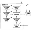
- FIG. 2 is a block diagram showing an example of a schematic configuration of the in-vehicle system.
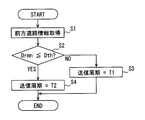
- FIG. 3 is a flowchart for explaining the transmission cycle control process.
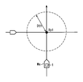
- FIG. 4 is a diagram for explaining the operation of the present embodiment.
- FIG. 5 is a diagram for explaining the operation of the present embodiment.
- FIG. 6 is a block diagram illustrating a schematic configuration of the communication control unit in the fourth modification.
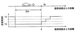
- FIG. 7 is a diagram for explaining the operation of the transmission control unit in the modified example 5.
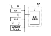
- FIG. 8 is a block diagram for explaining the configuration of the in-vehicle system in Modification 8.
- FIG. 1 is a diagram illustrating an example of a schematic configuration of a vehicle-to-vehicle communication system 100 according to the present disclosure.
- the inter-vehicle communication system 100 includes a plurality of in-vehicle systems 1 constructed in each of a plurality of vehicles Ma and Mb, and a center 2.
- FIG. 1 only two vehicles Ma and Mb are illustrated as vehicles to which the in-vehicle system 1 is applied (hereinafter referred to as “applicable vehicles”) for the sake of convenience. Good.
- applicable vehicles for the sake of convenience.
- the in-vehicle system 1 constructed in the vehicle Ma is used as the in-vehicle system 1a
- the in-vehicle system 1 constructed in the vehicle Mb is installed in the vehicle. It is described as a system 1b.
- the inter-vehicle communication system 100 is a system for applying vehicles to perform wireless communication with each other via the wide area communication network 3.
- the applicable vehicle is a vehicle that travels on a road.
- the applicable vehicle may be a two-wheeled vehicle, a three-wheeled vehicle, etc. in addition to a four-wheeled vehicle.
- motorcycles include motorbikes.
- the applied vehicles Ma and Mb are assumed to be four-wheeled vehicles as an example.
- Each applicable vehicle is configured to be wirelessly connectable to the wide area communication network 3 by the in-vehicle system 1 mounted on the vehicle.
- the wide area communication network 3 refers to a public communication network provided by a telecommunication carrier such as a mobile phone network or the Internet.
- a base station 4 shown in FIG. 1 is a radio base station for connecting the in-vehicle system 1 to the wide area communication network 3.
- communication via the wide area communication network 3 is simply referred to as wide area communication.
- Each applicable vehicle transmits a vehicle information packet indicating its own vehicle information to the center 2 via the base station 4 and the wide area communication network 3 at a predetermined transmission cycle.
- the vehicle information packet here is a communication packet indicating the vehicle information of the vehicle (that is, the transmission source vehicle) that has transmitted the vehicle information packet.
- the vehicle information includes the current position, traveling direction, traveling speed, acceleration, and the like of the transmission source vehicle.
- the vehicle information packet includes information such as the transmission time of the communication packet and transmission source information.
- the transmission source information is an identification number (so-called vehicle ID) assigned to the vehicle corresponding to the transmission source.
- the center 2 plays a role of transferring a vehicle information packet transmitted from a certain vehicle to other vehicles (that is, surrounding vehicles) existing around the transmission source vehicle.
- the area around the transmission source vehicle is a range within a predetermined inter-vehicle distance from the vehicle. That is, the inter-vehicle distance for transfer functions as a parameter used to extract a vehicle (in other words, a surrounding vehicle for the transmission source vehicle) as a transfer destination of the vehicle information packet received from among various applicable vehicles.
- the inter-vehicle distance for transfer may be a fixed value, or may be dynamically determined according to the traveling speed of the transmission source vehicle, the type of road on which the vehicle is traveling, and the like.
- the transfer inter-vehicle distance is set to a larger value as the traveling speed of the transmission source vehicle increases.
- the inter-vehicle distance for transfer may be a value corresponding to the type of road on which the transmission source vehicle is traveling.
- the distance between the transfer vehicles is a value corresponding to the type of the traveling road
- the distance between the transfer vehicles when the traveling road is a highway is set to a relatively large value (for example, 400 m)
- the traveling road is In the case of a general road, it may be set to a smaller value than when the traveling road is a highway.
- Other vehicles existing within the inter-vehicle distance for transmission from the transmission source vehicle correspond to surrounding vehicles for the transmission source vehicle.
- the center 2 has a function of managing the current position of each applicable vehicle as a sub-function for determining the transfer destination of the received vehicle information packet.
- the management of the current position of each applicable vehicle may be realized using a database (not shown).
- the current position of each applicable vehicle is stored in association with the vehicle ID or the like.
- data representing the current position for each applicable vehicle is referred to as position management data.
- the center 2 updates the current position of the transmission source vehicle registered in the database.
- the center 2 When the center 2 receives a vehicle information packet from a certain application vehicle, the center 2 extracts a vehicle existing at a position that is within the inter-vehicle distance for transfer within a straight line distance from the transmission source vehicle based on the position management data. The received vehicle information packet is transferred to the extracted vehicle.
- the inter-vehicle communication system 100 provides inter-vehicle communication via the wide area communication network.
- the configuration of the in-vehicle system 1 mounted on each vehicle will be described in more detail.
- the configuration of the in-vehicle system 1 will be described taking the in-vehicle system 1a mounted in the applicable vehicle Ma as an example.
- the in-vehicle system 1 constructed in another applicable vehicle (for example, the vehicle Mb) has the same configuration.
- the vehicle on which the vehicle-mounted system 1 is mounted that is, the vehicle Ma
- the own vehicle as distinguished from the vehicle mounted with the other vehicle-mounted system 1.
- the in-vehicle system 1 includes a communication unit 10, a sensor 20, and a locator 30, as shown in FIG.
- the communication unit 10 is connected to the sensor 20 and the locator 30 via a communication network (ie, LAN: Local Area Network) built in the vehicle.
- a communication network ie, LAN: Local Area Network
- the communication unit 10 is a unit for performing transmission and reception of vehicle information packets.
- the communication unit 10 generates a vehicle information packet based on the information provided from the sensor 20 and transmits the vehicle information packet to other vehicles (hereinafter referred to as surrounding vehicles) existing around the host vehicle via the center 2. Further, the communication unit 10 receives the vehicle information packet transmitted from the surrounding vehicle via the center 2. Details of the communication unit 10 will be described later.
- the sensor 20 is various sensors for detecting various state quantities related to the traveling of the host vehicle.
- the state quantities related to the traveling of the host vehicle are, for example, a traveling speed, a yaw rate, a steering angle, an acceleration, a shift position, and the like. That is, the sensor 20 includes a speed sensor that detects a traveling speed, a yaw rate sensor that detects a yaw rate, a steering angle sensor that detects a steering angle, an acceleration sensor that detects acceleration acting on the vehicle Ma, a shift position sensor, and the like. . Note that the current position of the host vehicle specified by a locator 30 described later is also included in the state quantity related to the traveling of the host vehicle.
- the sensor 20 sequentially provides detection values of state quantities indicating the traveling state of the vehicle Ma to the communication unit 10 via the LAN.
- the detection results of the various sensors 20 may be provided to the communication unit 10 via an ECU (Electronic Control Unit) or the like.
- the sensor corresponding to the sensor 20 is not limited to that described above. Moreover, it is not necessary to provide all the sensors mentioned above. The kind of sensor 20 should just be designed suitably.
- Locator 30 is a device that identifies a point where the host vehicle is currently traveling on a road map.
- the locator 30 includes a GNSS receiver 31 and a map storage unit 32 as finer components.
- the GNSS receiver 31 receives a navigation signal transmitted by a navigation satellite provided in a GNSS (Global Navigation Satellite System), which is a satellite navigation system, and sequentially calculates a current position based on the received navigation signal.
- GNSS Global Navigation Satellite System
- the map storage unit 32 stores road map data indicating road connection relations and road shapes (in other words, road structures).
- the map storage unit 32 may be realized using a non-volatile storage medium such as a hard disk drive.
- the map storage unit 32 may be provided as a map database outside the vehicle.
- the in-vehicle system 1 is configured to be accessible to a map database as the map storage unit 32 via the wide area communication network 3.
- the road map data includes node data for each node and link data for each link.
- a node is a point that is appropriately set to represent a road connection relationship, such as a connection point between roads (hereinafter referred to as a road connection point) or a road end point.
- a link is a link between nodes. It is a connecting road.
- the road connection point is, for example, an intersection.
- the road connection point includes a junction point where the main highway and the rampway are connected.
- a rampway is a road connecting a highway and a general road.
- Each node is assigned a unique node ID, and each link is assigned a unique link ID.
- Various nodes and links that construct the road network are identified by the node ID and the link ID.
- the node data for a certain node includes a node ID, coordinate information indicating the position of the node, a node type, and information on a link connected to the node (for example, a link ID).
- the node type is information indicating a type as a road binding point, for example, information indicating whether the node is an intersection or a merging point set on an expressway.
- the link data includes a link ID, a link length, a link shape, a node ID corresponding to the start end of the link, a node ID corresponding to the end, road width, lane information, speed limit, and the like.
- the link shape includes a road gradient.
- Locator 30 specifies the position of the host vehicle on the road map based on the current position detected by GNSS receiver 31.
- the identification of the vehicle position on the road map is hereinafter referred to as mapping.
- the mapping of the vehicle position may be performed with the aid of a known map matching technique commonly used in navigation devices.
- the map matching technique is a technique for obtaining the vehicle travel locus from the traveling direction and the traveling speed of the vehicle at a plurality of time points, and comparing the vehicle travel locus and the road shape obtained from the map information to obtain the current position of the vehicle. .
- the locator 30 sequentially identifies the road on which the host vehicle is traveling (hereinafter referred to as the host vehicle travel path) based on the result of mapping to the host vehicle. Then, the communication unit 10 is provided with road map information (hereinafter referred to as forward road information) regarding the identified own vehicle travel path.
- the host vehicle travel path the road on which the host vehicle is traveling
- the communication unit 10 is provided with road map information (hereinafter referred to as forward road information) regarding the identified own vehicle travel path.
- the forward road information includes the position of the road connection point existing in the traveling direction of the host vehicle (in other words, the front side) and the road connection existing closest to the host vehicle among the road connection points existing in front of the host vehicle.
- the remaining distance Drmn to the point hereinafter referred to as the nearest connection point
- information indicating the road shape of the own vehicle travel path hereinafter referred to as road shape information
- the road shape information preferably includes road gradient, curvature, and the like.
- the locator 30 may provide link data corresponding to the own vehicle travel path as road shape information.
- the locator 30 also sequentially provides the communication unit 10 with position information indicating the current position specified by the GNSS receiver 31 in addition to the above-described forward road information.
- the locator 30 since the road connection point that has passed does not correspond to the nearest connection point, when the locator 30 detects that the vehicle has passed the point that was handled as the nearest connection point, the next road connection point becomes the nearest connection point. Set.
- the locator 30 only needs to have the above-described function.
- the navigation device When the navigation device is mounted on the host vehicle, the navigation device may be used as the locator 30.
- the communication unit 10 includes a wide area communication module 11 and a communication control unit 12.
- the communication control unit 12 corresponds to a communication control device.
- the wide area communication module 11 is a communication module that is wirelessly connected to the wide area communication network 3 so that the in-vehicle system 1 performs wide area communication with other communication devices.
- the wide area communication module 11 includes a wide area communication antenna and a transmission / reception unit (not shown) as finer elements.
- the wide area communication antenna is an antenna for transmitting and receiving radio waves of a predetermined frequency band used for wide area communication.
- the transmission / reception unit demodulates a signal received by the wide-area communication antenna and provides it to the communication control unit 12, modulates data input from the communication control unit 12, outputs the modulated data to the wide-area communication antenna, and wirelessly transmits the data.
- the wide-area communication module 11 outputs the received data to the communication control unit 12 and modulates the data input from the communication control unit 12 to external devices (for example, the center). It functions as a communication module that transmits to 2).
- the communication control unit 12 controls the operation of the wide area communication module 11.
- the communication control unit 12 is configured as a computer including a CPU, a RAM, a ROM, an I / O, and a bus line that connects these configurations.
- the ROM stores a program (hereinafter referred to as a communication control program) for causing a normal computer to function as the communication control unit 12.
- the above-described communication control program only needs to be stored in a non-transitory tangible storage medium, and the specific storage medium is not limited to the ROM.
- the communication control program may be stored in a flash memory. Executing the communication control program by the CPU corresponds to executing a method corresponding to the communication control program.
- the communication control unit 12 provides various functions shown in FIG. 2 when the CPU executes the communication control program stored in the ROM. That is, the communication control unit 12 includes a vehicle information acquisition unit F1, a communication packet generation unit F2, a road information acquisition unit F4, a positional relationship determination unit F5, a transmission control unit F3, and a reception data acquisition unit F6 as functional blocks.
- some or all of the functional blocks included in the communication control unit 12 may be realized by using one or a plurality of ICs (in other words, as hardware). In addition, some or all of the functional blocks included in the communication control unit 12 may be realized by a combination of execution of software by the CPU and hardware members.
- the vehicle information acquisition unit F1 acquires various information (that is, vehicle information) indicating the traveling state of the host vehicle from the sensor 20 and the locator 30. Specifically, the current position of the host vehicle, the traveling speed, the yaw rate, the traveling direction, and the like are acquired. Various information acquired by the vehicle information acquisition unit F1 is stored in a RAM (not shown) for a certain period of time.
- the communication packet generator F2 generates a vehicle information packet using the vehicle information stored in the RAM.
- the communication packet generation unit F2 generates a vehicle information packet based on a request from the transmission control unit F3.
- the communication packet generator F2 may generate the vehicle information packet at a predetermined generation cycle.
- the transmission control unit F3 is a functional block that controls the transmission interval of vehicle information packets.
- the transmission control unit F3 includes a timer (hereinafter referred to as a transmission timer) for transmitting the vehicle information packet at a predetermined transmission cycle as a sub-function for controlling the transmission interval of the vehicle information packet.
- the transmission timer is a timer that measures the elapsed time since the last transmission of the vehicle information packet.
- the state in which the count value of the transmission timer becomes a value corresponding to the transmission cycle corresponds to the timer expiration state.
- the transmission timer is reset and restarted every time a vehicle information packet is transmitted.
- the operation of the transmission control unit F3 and the communication packet generation unit F2 may be designed as appropriate.
- the transmission control unit F3 and the communication packet generation unit F2 cooperate as follows to transmit vehicle information packets at a predetermined transmission cycle. That is, the transmission control unit F3 requests the communication packet generation unit F2 to generate a vehicle information packet when the transmission timer expires. And the vehicle information packet produced
- the transmission cycle itself corresponding to the transmission interval of the vehicle information packet is dynamically changed by the transmission control unit F3.
- first and second periods T1 and T2 having different lengths are registered in advance in the ROM as setting values that can be adopted as the transmission period of the vehicle information packet.
- the transmission control unit F3 selects a value to be adopted as the transmission cycle from the first cycle T1 and the second cycle T2 based on the determination result of the positional relationship determination unit F5 described later.
- the first period T1 is 1 second, and the second period T2 is 0.1 seconds.
- the first period T1 only needs to be set to a time longer than the second period T2.
- the first period may be 0.5 seconds or 0.8 seconds.
- the first period T1 is preferably set to a relatively long value from the viewpoint of suppressing traffic.
- the second period T2 is a value used when real-time information sharing is required.
- a value of about several hundred milliseconds is assumed as the transmission cycle of the vehicle information packet in the conventional inter-vehicle communication system. Therefore, it is preferable to set it to a relatively small value (for example, 300 milliseconds or less) from the viewpoint of real-time information sharing.
- the transmission control unit F3 corresponds to a transmission processing unit.
- the first period T1 may be designed to be a large value (for example, 10,000 seconds or more) such that the transmission of the vehicle information packet is not substantially performed.
- the first period T1 may be set to a value that is treated as infinite by the transmission control unit F3.
- the transmission control unit F3 may be configured not to transmit the vehicle information packet when the transmission cycle is set to the first cycle T1.
- the road information acquisition unit F4 acquires front road information from the locator 30.
- the acquired forward road information is provided to the positional relationship determination unit F5.
- the road information ahead includes the remaining distance Drmn to the nearest connection point.
- the positional relationship determination unit F5 determines whether or not the remaining distance Drmn to the nearest connection point included in the forward road information acquired by the road information acquisition unit F4 is equal to or less than a predetermined period change distance Dth. In other words, the positional relationship determination unit F5 determines whether or not the host vehicle exists in a range that is within the period change distance Dth from the nearest connection point.
- the cycle change distance Dth is a distance used to determine whether or not the transmission cycle T of the vehicle information packet should be set to a second cycle T2 that is shorter than a predetermined first cycle T1.
- the period change distance Dth may be a fixed value designed in advance, or may be dynamically determined (in other words, adjusted) according to the traveling speed of the host vehicle.
- the positional relationship determination unit F5 sets the cycle change distance Dth to a larger value as the traveling speed of the host vehicle increases. For example, when the traveling speed of the host vehicle is equal to or less than the cruising speed of a general road (for example, 50 km / h), it is set to 200 m, and when the traveling speed is equivalent to the cruising speed of an expressway (for example 80 km / h) Set to 400m. A specific value of the period change distance Dth corresponding to the traveling speed may be designed as appropriate.
- the reception data acquisition unit F6 acquires data (for example, vehicle information packets from other vehicles) received by the wide area communication module 11.
- the vehicle information packet acquired by the reception data acquisition unit F6 is stored for a certain time in a RAM or the like while being distinguished for each vehicle, or provided to another electronic control unit (ECU: Electronic Control Unit) via the LAN.
- ECU Electronic Control Unit
- the transmission cycle control process is a process for controlling the transmission cycle of the vehicle information packet. This transmission cycle control process may be started sequentially (for example, every 50 milliseconds) while the power source of the vehicle (for example, the ignition power source) is on.
- step S1 the road information acquisition unit F4 acquires the front road information provided from the locator 30, and proceeds to step S2.
- the positional relationship determination unit F5 determines whether the remaining distance Drmn to the nearest connection point is equal to or less than the cycle change distance Dth. If the remaining distance Drmn to the nearest connection point is less than or equal to the period change distance Dth, an affirmative determination is made in step S2 and the process proceeds to step S4. On the other hand, if the remaining distance Drmn to the nearest connection point is not less than or equal to the period change distance Dth, a negative determination is made in step S2 and the process proceeds to step S3. Note that the cycle change distance Dth is adjusted to a value according to the current traveling speed of the host vehicle by the positional relationship determination unit F5.
- step S3 the transmission control unit F3 sets the transmission cycle to the first cycle T1, and ends this flow.
- step S4 the transmission control unit F3 sets the transmission cycle to the second cycle T2, and ends this flow.
- the remaining distance Drmn to the nearest connection point is equal to or less than the period change distance Dth suggests that the vehicle will soon enter a point where it joins with another road such as an intersection (ie, a road connection point). Moreover, when the remaining distance Drmn to the nearest connection point is larger than the period change distance Dth, it indicates that the vehicle is traveling along a road away from a road connection point such as an intersection.
- the communication unit 10 transmits a vehicle information packet with a relatively long transmission cycle when the host vehicle is in an area away from the intersection or the like, and enters the intersection or the like soon.
- the vehicle information packet is transmitted with a relatively short transmission cycle.
- the lengthening of the transmission cycle corresponds to the suppression of the transmission frequency of vehicle information packets (in other words, the communication volume). Shortening the transmission cycle is equivalent to increasing the frequency of transmission of vehicle information packets and more densely transmitting information to other vehicles.
- the vehicle may enter an intersection or the like. is assumed.
- the usefulness of the vehicle information of other vehicles is relatively low compared to immediately before entering the intersection.
- the communication control unit 12 in the above configuration shortens the transmission interval in a scene where the necessity of sharing each vehicle information is relatively high, and in a scene where the necessity for sharing the vehicle information is relatively low.
- the transmission cycle is controlled in accordance with the positional relationship between a road connection point such as an intersection and the own vehicle so as to increase the transmission interval.
- the vehicle information packet can be transmitted at a more appropriate transmission cycle.
- FIG. 4 and 5 are diagrams for explaining the operation of the vehicle-to-vehicle communication system 100 as a whole.
- Xp1 shown in FIG. 4 and Xp2 shown in FIG. 5 represent the positions of the nearest connection points, and an area surrounded by a broken line is an area in which the distance from the nearest connection point is equal to or less than the period change distance Dth (hereinafter, an area near the connection point) ).
- the point Xp1 represents the intersection of a general road
- the point Xp2 represents the junction point to the highway main line.
- the area near the connection point functions as an area where inter-vehicle communication is densely performed.
- the area outside the connection point area functions as an area where inter-vehicle communication is suppressed.
- the communication control unit 12 may include some of the functions of the locator 30.
- the positional relationship determination unit F5 may operate by adjusting the period change distance Dth according to the weather and the road surface condition.
- the road surface state indicates whether the road surface is wet, snowy, frozen, or whether the road is paved.
- the road surface state may be represented by a friction coefficient of the road surface.
- the weather here refers to the presence or absence of rain, snow, or fog. In any case, it is assumed that the positional relationship determination unit F5 operates by correcting the period change distance Dth to a longer value as the road surface frictional force of the host vehicle traveling path is smaller.
- the information indicating the road surface condition may be acquired from the sensor 20 mounted on the vehicle, or may be acquired from an external server or the like via the wide area communication network 3.
- Examples of the sensor that senses the state quantity indicating the road surface state include a rain sensor that detects rainfall.
- Various techniques for detecting the frictional force between the tire and the road surface have been proposed, and the road surface state may be determined by using these known techniques.
- the positional relationship determination unit F5 may adjust the period change distance Dth based on the road gradient of the own vehicle travel path. Specifically, the cycle change distance Dth is decreased by a predetermined amount when the road is uphill, and the cycle change distance Dth is increased by a predetermined amount when the road is downhill. This is because the braking force of the vehicle changes according to the gradient, and accordingly, the time required for adjusting the inter-vehicle distance also changes. Basically, the period change distance Dth only needs to be reduced as the situation where the vehicle is more easily decelerated. A specific adjustment amount may be designed as appropriate.
- the mode in which the period change distance Dth is adjusted according to the traveling speed is exemplified, but the present invention is not limited to this.
- the period change distance Dth may be determined according to the node type of the nearest connection point. A relatively large value is set when the nearest connection point is a junction with the expressway main line, and a relatively small value is set when the nearest connection point is an intersection of a general road.
- the traveling speed on ordinary roads is not as great as when driving on highways. Therefore, the cycle change distance can be indirectly set to a value corresponding to the traveling speed of the host vehicle or the surrounding vehicles also by such an aspect.
- the value of the period change distance Dth may be adjusted based on both the traveling speed and the node type. The adjustment method in that case may be appropriately designed based on the above-described idea.
- the communication control unit 12 determines whether or not there is a surrounding vehicle, and maintains the second cycle T2 as a transmission cycle when there is no surrounding vehicle even if the remaining distance Drmn to the nearest connection point is present. May be. If there is no surrounding vehicle, the transmitted vehicle information packet is not used by the surrounding vehicle. For this reason, there is little need to shorten the transmission cycle.
- FIG. 6 is a functional block diagram schematically illustrating functions of the communication control unit 12 according to the fourth modification.
- the communication control unit 12 in the modification 4 includes a surrounding vehicle determination unit F7 as a function block in addition to the various functions described above.
- the surrounding vehicle determination unit F7 is a functional block that determines whether there is a surrounding vehicle.
- the presence / absence of a surrounding vehicle may be determined based on whether or not the vehicle information packet of another vehicle has been transferred from the center 2. For example, if a vehicle information packet of another vehicle has not been received within the determination time from the present time, it is determined that there is no surrounding vehicle. On the other hand, when the vehicle information packet of the other vehicle is received within the determination time, it is determined that there is a surrounding vehicle.
- the determination time may be designed as appropriate. However, it is preferable that the determination time is longer than one time of the first period T1. For example, the determination time may be set to twice the first period T1. Whether or not the vehicle information packet of another vehicle has been received within the determination time can be specified by referring to the RAM. This is because the vehicle information packet acquired by the reception data acquisition unit F6 is stored in the RAM.
- the transmission control unit F3 in Modification 4 determines that the remaining distance Drmn is less than or equal to the period change distance Dth by the positional relationship determination unit F5, and if the surrounding vehicle determination unit F7 determines that there is a surrounding vehicle.
- the transmission cycle is set to the second cycle T2.
- the positional relationship determination unit F5 determines that the remaining distance Drmn is not less than or equal to the cycle change distance Dth, and if the surrounding vehicle determination unit F7 determines that there is no surrounding vehicle, the transmission cycle is set. Set to the first period T1.
- the amount of communication can be further suppressed.
- the 2nd period T2 is employ
- the host vehicle immediately after passing through the road connection point, the host vehicle is still in the vicinity of the point Xp, so that the vehicle information packet of the host vehicle is still useful for other vehicles passing through the point Xp. There can be.
- the transmission control unit F3 may maintain the transmission cycle at the second cycle T2 after moving through the road connection point Xp until moving from the point by a predetermined cycle return distance.
- the period return distance may be designed as appropriate, and may be the same value as the period change distance Dth.
- the transmission control unit F3 returns the transmission cycle from the second cycle T2 to the first cycle T1, as shown in FIG. 7, the first cycle T1 is continuously or stepwise (that is, gradually) from the second cycle. It is good also as a mode to return to.
- the case of returning from the second period T2 to the first period T1 is a case of passing through the point Xp that has been handled as the latest connection point.
- the vehicle information packet of the host vehicle may still be useful for other vehicles that are about to pass the point Xp.
- Vehicle information packets of vehicles can be provided at relatively short intervals.
- the transmission cycle employed in the process of returning the transmission cycle from the second cycle T2 to the first cycle T1 is a value corresponding to the distance between the point Xp, which has been handled as the nearest connection point, and the own vehicle, and the elapsed time since passing through. And it is sufficient. It is assumed that the transmission period approaches the first period T1 as the distance from the point Xp increases or the elapsed time after passing through the point Xp is longer.
- the set value as the transmission cycle may be determined and updated at the timing when the vehicle information packet is transmitted, in other words, when the transmission timer is restarted.
- the mode in which the transmission cycle is gradually switched from the second cycle T2 to the first cycle T1 is exemplified.
- the change from the first cycle T1 to the second cycle T2 is also stepwise according to the remaining distance Drmn. May be migrated.
- a specific value of the transmission period corresponding to the remaining distance Drmn may be designed as appropriate.
- the transmission cycle is set from the first cycle so that the remaining distance Drmn is larger than the cycle change distance Dth so that the transmission cycle becomes the second cycle T2. It is preferable to start shortening.
- the road information acquisition unit F4 acquires the front road information from the locator 30, but is not limited thereto.
- the in-vehicle system 1 includes an in-vehicle camera that captures the front of the vehicle, by analyzing an image captured by the in-vehicle camera, an intersection or the like is detected, or the remaining distance to the detected intersection is specified. Also good. That is, the in-vehicle camera may be the source device for the road information ahead.
- the technique for detecting a predetermined detection target from the captured image of the in-vehicle camera is well known as an image recognition technique, a description of a specific implementation method thereof is omitted.
- An intersection or the like may be detected using a traffic light or a road sign as a landmark.
- the front road information may be acquired by using the environment recognition based on the captured image of the in-vehicle camera and the locator 30 in combination.
- the communication control unit 12 adopts the second cycle T2 as the transmission cycle for the surrounding vehicles when the condition for adopting the second cycle T2 (hereinafter, the second cycle condition) is satisfied.
- a second periodic request packet to be requested may be generated and transmitted.
- the generation itself of the second periodic request packet may be performed by the communication packet generator F2.
- the transmission controller F3 may determine whether or not the second periodic request packet should be transmitted, in other words, whether or not the second periodic condition is satisfied.
- the case where the second periodic condition is satisfied is a case where the remaining distance Drmn is equal to or less than the period change distance Dth in the embodiment, and in the fourth modification, the remaining distance Drmn is the period change distance Dth. This is a case where there is a surrounding vehicle.
- the content of the second periodic condition may be designed as appropriate.
- the second periodic request packet transmitted by the transmission control unit F3 in cooperation with the wide area communication module 11 is transferred by the center 2 to surrounding vehicles.
- the center 2 receives the second periodic request packet from the vehicle Ma, for example, the center 2 identifies the surrounding vehicle of the vehicle Ma and transfers the second periodic request packet to the identified surrounding vehicle.
- Each in-vehicle system 1 adopts the second period T2 as the transmission period when receiving the second periodic request packet.
- the transmission control unit F3 does not transmit the second periodic request packet when the transmission period is set to the second period T2 triggered by the reception of the second periodic request packet. If the second periodic request packet is transmitted even when the transmission period is set to the second period T2 when the second periodic request packet is received, the second periodic request packet spreads in a chain. It is because it will do.
- the vehicle information packet can be transmitted to the surrounding vehicles at the second period T2. Therefore, according to the configuration of the modification 8, real-time vehicle information sharing can be realized more reliably.
- the transmission control unit F3 after transmitting the second periodic request packet, the transmission control unit F3, when the second periodic condition is not satisfied, the communication packet that permits the transmission period to return to the first period T1 ( Hereinafter, it is assumed that a return permission packet) is transmitted over a wide area.
- the transmission control unit F3 When the transmission control unit F3 receives the second periodic request packet from another vehicle, the transmission control unit F3 registers information (for example, vehicle ID) indicating the transmission source of the communication packet in the RAM or the like as the request source vehicle. And when the return permission packet is received from all the request source vehicles, the transmission cycle is returned from the second cycle T2 to the first cycle T1.
- information for example, vehicle ID
- a vehicle that can no longer receive the vehicle information packet is likely to be no neighboring vehicle for the own vehicle. Therefore, the registration of the requesting vehicle may be canceled for the vehicle that can no longer receive the vehicle information packet.
- the wide area communication module 11 is provided outside the unit 10A including the communication control unit 12, and is configured such that the wide area communication module 11 and the communication control unit 12 are connected via a LAN. Also good.
- each section is expressed as, for example, S1. Further, each section can be divided into a plurality of subsections, while a plurality of sections can be combined into one section. Further, each section configured in this manner can be referred to as a device, module, or means.
Landscapes
- Engineering & Computer Science (AREA)
- Computer Networks & Wireless Communication (AREA)
- Signal Processing (AREA)
- Physics & Mathematics (AREA)
- General Physics & Mathematics (AREA)
- Quality & Reliability (AREA)
- Databases & Information Systems (AREA)
- Traffic Control Systems (AREA)
- Mobile Radio Communication Systems (AREA)
Abstract
車両用通信制御装置は、車両の走行状態を示す車両情報パケットを生成する通信パケット生成部(F2)と、前記車両情報パケットを所定の送信周期で周辺車両へ送信する送信処理部(F3)と、前記車両の自車走行路が他の道路と接続する道路接続点の位置を含む前方道路情報を取得する道路情報取得部(F4)と、前記前方道路情報に基づいて、前記車両がこれから通行する前記道路接続点までの残り距離が所定の周期変更距離以下となっているか判定する位置関係判定部(F5)とを備える。前記送信処理部は、前記残り距離が前記周期変更距離よりも大きい場合には、前記送信周期として所定の第1周期を採用し、残り距離が前記周期変更距離以下である場合には、前記送信周期として前記第1周期よりも短い第2周期を採用する。
Description
本出願は、2016年3月18日に出願された日本特許出願番号2016-55974号に基づくもので、ここにその記載内容を援用する。
本開示は、車車間通信を実施するための通信モジュールの動作を制御する通信制御装置に関するものである。
近年、複数の車両のそれぞれが、現在位置や、走行速度、進行方向などの車両情報を示す通信パケット(以降、車両情報パケット)を逐次同報送信するとともに、他車両から送信された車両情報パケットを逐次受信する車車間通信システムが提案されている。
そのような車車間通信システムにおける車両同士の通信(つまり車車間通信)の態様としては、特許文献1に開示されているように、広域通信網を経由せずに、車両同士が車両情報パケットを直接送受信する態様が想定されている。車両同士の直接的な無線通信は、アクセス制御方式としてCSMA/CA(Carrier Sense Multiple Access/Collision Avoidance)方式を採用することで実現される。
車車間通信の実現態様としては、車両同士が広域通信網を介して車両情報パケットを送受信する態様も考えられる。しかしながら、車両同士が広域通信網を経由して通信する場合には、通信量を抑制するために車両情報パケットの送信頻度を抑えたいという要求と、リアルタイムな車両情報を互いに共有させるために車両情報パケットの送信間隔を短くしたいという要求の、互いに相反する要求が存在する。
本開示は、広域通信網を介した車車間通信を提供する車車間通信システムで用いられる通信制御装置であって、リアルタイムな車両情報の共有を実現しつつ、通信量を抑制可能な通信制御装置を提供することを目的とする。
本開示の態様において、車両で用いられ、前記車両の周辺に存在する周辺車両との広域通信網を介した無線通信を制御する通信制御装置は、前記車両に搭載されているセンサの検出結果に基づいて、前記車両の走行状態を示す通信パケットである車両情報パケットを生成する通信パケット生成部と、前記通信パケット生成部が生成した前記車両情報パケットを所定の送信周期で前記周辺車両へ送信するための処理を行う送信処理部と、前記車両が走行している道路である自車走行路が他の道路と接続する点である道路接続点の位置を含む前方道路情報を取得する道路情報取得部と、前記道路情報取得部が取得した前記前方道路情報に基づいて、前記車両がこれから通行する前記道路接続点までの残り距離が所定の周期変更距離以下となっているか否かを判定する位置関係判定部(F5)と、を備える。前記送信処理部は、前記位置関係判定部によって前記道路接続点までの残り距離が前記周期変更距離よりも大きいと判定されている場合には、前記送信周期として所定の第1周期を採用する一方、前記位置関係判定部によって前記道路接続点までの残り距離が前記周期変更距離以下であると判定されている場合には、前記送信周期として前記第1周期よりも短い第2周期を採用する。
ここでの道路接続点とは道路と道路が接続する点であり、具体的には、交差点や、高速道路本線への合流地点などが該当する。一般的に、道路接続点から離れたエリアを走行している場合には、道路接続点付近を走行している場合に比べて相対的に他車両の車両情報の有用性は低い。ドライバの運転支援や自動運転等のために他車両のリアルタイムな車両情報が必要な(換言すれば有用な)場面とは、交差点等などの道路接続点付近を走行する場合であることが多いためである。
そのような事情に対して以上の構成では、送信処理部は、車両前方に存在する道路接続点までの残り距離が所定の周期変更距離よりも大きい場合には、相対的に長い第1周期で車両情報パケットが逐次送信されるように処理する一方、残り距離が周期変更距離以下となっている場合には、相対的に短い第2周期で車両情報パケットが逐次送信されるように処理を行う。
したがって、上述した通信制御装置が適用されている車両は、道路接続点から周期変更距離以内となるエリアに進入すると、相対的に短い送信周期で車両情報パケットを送信し始める。つまり、道路接続点付近においては、各適用車両が相対的に短い送信周期で車両情報パケットを送信するため、リアルタイムな車両情報の共有が実現される。
一方、リアルタイムな車両情報の有用性が相対的に低いエリア、すなわち道路接続点から離れたエリアにおいては、送信周期として相対的に長い第1周期が採用されるため、通信量を抑制することができる。つまり、以上の構成によればリアルタイムな車両情報の共有を実現しつつ、通信量を抑制することができる。
本開示についての上記目的およびその他の目的、特徴や利点は、添付の図面を参照しながら下記の詳細な記述により、より明確になる。その図面は、
図1は、車車間通信システムの概略的な構成の一例を示すブロック図であり、
図2は、車載システムの概略的な構成の一例を示すブロック図であり、
図3は、送信周期制御処理を説明するためのフローチャートであり、
図4は、本実施形態の作動を説明するための図であり、
図5は、本実施形態の作動を説明するための図であり、
図6は、変形例4における通信制御部の概略的な構成を示すブロック図であり、
図7は、変形例5における送信制御部の作動を説明するための図であり、
図8は、変形例8における車載システムの構成を説明するためのブロック図である。
以下、本開示の実施形態について図を用いて説明する。図1は、本開示に係る車車間通信システム100の概略的な構成の一例を示す図である。図1に示すように、車車間通信システム100は、複数の車両Ma,Mbの各々に構築されている複数の車載システム1と、センタ2と、を備える。
なお、図1では、便宜上、車載システム1が適用されている車両(以降、適用車両)として、車両Maと車両Mbの2台しか図示していないが、実際には3台以上存在してもよい。以降において、車両Ma,Mbに構築されている各車載システム1を区別する場合には、車両Maに構築されている車載システム1を車載システム1a、車両Mbに構築されている車載システム1を車載システム1bと記載する。
<全体の概要>
車車間通信システム100は、適用車両が広域通信網3を介して互いに無線通信を実施するためのシステムである。適用車両は、道路上を走行する車両である。適用車両は、四輪自動車のほか、二輪自動車、三輪自動車等であってもよい。二輪自動車には原動機付き自転車も含まれる。本実施形態では一例として適用車両Ma,Mbは、四輪自動車とする。
車車間通信システム100は、適用車両が広域通信網3を介して互いに無線通信を実施するためのシステムである。適用車両は、道路上を走行する車両である。適用車両は、四輪自動車のほか、二輪自動車、三輪自動車等であってもよい。二輪自動車には原動機付き自転車も含まれる。本実施形態では一例として適用車両Ma,Mbは、四輪自動車とする。
各適用車両は、それぞれに搭載されている車載システム1によって広域通信網3に無線接続可能に構成されている。なお、ここでの広域通信網3とは、携帯電話網やインターネット等の、電気通信事業者によって提供される公衆通信ネットワークを指す。図1に示す基地局4は、車載システム1が広域通信網3に接続するための無線基地局である。以降では便宜上、広域通信網3を介した通信を広域通信とも簡略して記載する。
各適用車両は、自分自身の車両情報を示す車両情報パケットを所定の送信周期で基地局4及び広域通信網3を介してセンタ2へ送信する。ここでの車両情報パケットとは、その車両情報パケットを送信した車両(つまり送信元車両)の車両情報を示す通信パケットである。車両情報には、送信元車両の現在位置、進行方向、走行速度、加速度などが含まれる。車両情報パケットには、車両情報のほかに、当該通信パケットの送信時刻や、送信元情報などの情報を含む。送信元情報とは、送信元に相当する車両に割り当てられている識別番号(いわゆる車両ID)である。
センタ2は、或る車両から送信された車両情報パケットを、その送信元車両の周辺に存在する他車両(つまり周辺車両)に転送する役割を担う。送信元車両の周辺とする領域は、その車両から所定の転送用車間距離以内となる範囲とする。つまり、転送用車間距離は、種々の適用車両の中から受信した車両情報パケットの転送先とする車両(換言すれば送信元車両にとっての周辺車両)を抽出するために用いられるパラメータとして機能する。
転送用車間距離は、一定値としてもよいし、送信元車両の走行速度や走行している道路の種別などに応じて動的に決定されてもよい。ここでは一例として転送用車間距離は、送信元車両の走行速度が大きいほど大きい値に設定されるものとする。他の態様として転送用車間距離を送信元車両が走行している道路の種別に応じた値としてもよい。仮に転送用車間距離を走行道路の種別に応じた値とする場合には、走行道路が高速道路である場合の転送用車間距離は相対的に大きい値(例えば400m)とする一方、走行道路が一般道路である場合には、走行道路が高速道路である場合よりも小さい値に設定すれば良い。送信元車両から転送用車間距離以内に存在する他車両が送信元車両にとっての周辺車両に相当する。
センタ2は、受信した車両情報パケットの転送先を決定するためのサブ機能として、各適用車両の現在位置を管理する機能を備える。各適用車両の現在位置の管理は、図示しないデータベースを用いて実現されればよい。当該データベースにおいて各適用車両の現在位置は、車両IDなどと対応付けられて保存されている。便宜上、適用車両毎の現在位置を表したデータを位置管理データと称する。センタ2は、車両情報パケットを受信する度に、データベースに登録されている送信元車両の現在位置を更新する。
センタ2は、或る適用車両からの車両情報パケットを受信した場合に、位置管理データに基づいて、その送信元車両から直線距離において転送用車間距離以内となる位置に存在する車両を抽出し、その抽出した車両にむけて、受信した車両情報パケットを転送する。
このようにして、車車間通信システム100は広域通信網を介した車車間通信を提供する。以降では、各車両に搭載される車載システム1の構成について、より詳細に述べる。
<車載システム1の構成について>
ここでは、適用車両Maに搭載されている車載システム1aを例にとって車載システム1の構成について述べる。なお、他の適用車両(例えば車両Mb)に構築されている車載システム1も同様の構成となっている。便宜上、車載システム1にとって自分自身が搭載されている車両(つまり車両Ma)のことを、他の車載システム1が搭載されている車両と区別して、自車両とも記載する。
ここでは、適用車両Maに搭載されている車載システム1aを例にとって車載システム1の構成について述べる。なお、他の適用車両(例えば車両Mb)に構築されている車載システム1も同様の構成となっている。便宜上、車載システム1にとって自分自身が搭載されている車両(つまり車両Ma)のことを、他の車載システム1が搭載されている車両と区別して、自車両とも記載する。
車載システム1は、図2に示すように、通信ユニット10、センサ20、及びロケータ30を備える。通信ユニット10は、車両内に構築された通信ネットワーク(つまり、LAN:Local Area Network)を介して、センサ20、ロケータ30と接続されている。
通信ユニット10は、車両情報パケットの送受信を実施するためのユニットである。通信ユニット10は、センサ20から提供される情報に基づいて車両情報パケットを生成し、センタ2を介して自車両周辺に存在する他車両(以降、周辺車両)に送信する。また、通信ユニット10は周辺車両から送信された車両情報パケットをセンタ2経由で受信する。この通信ユニット10の詳細については別途後述する。
センサ20は、自車両の走行に関する種々の状態量を検出するための種々のセンサである。自車両の走行に関する状態量とは、例えば、走行速度、ヨーレート、操舵角、加速度、シフト位置などである。つまり、走行速度を検出する速度センサや、ヨーレートを検出するヨーレートセンサ、操舵角を検出する操舵角センサ、車両Maに作用する加速度を検出する加速度センサ、シフトポジションセンサ等が、センサ20に含まれる。なお、後述するロケータ30が特定する自車両の現在位置もまた、自車両の走行に関する状態量に含まれる。
センサ20は、車両Maの走行状態を示す状態量の検出値を、LANを介して通信ユニット10に逐次提供する。なお、種々のセンサ20の検出結果は、ECU(Electronic Control Unit)等を介して通信ユニット10に提供される構成となっていても良い。センサ20に該当するセンサは上述したものに限らない。また、上述した全てのセンサを備えている必要もない。センサ20の種類は適宜設計されればよい。
ロケータ30は、道路地図上において、自車両が現在走行している地点を特定する装置である。ロケータ30は、より細かい構成要素として、GNSS受信機31及び地図記憶部32を備える。
GNSS受信機31は、衛星航法システムであるGNSS(Global Navigation Satellite System)が備える航法衛星が送信する航法信号を受信し、受信した航法信号に基づいて現在位置を逐次算出する。
地図記憶部32は、道路の接続関係や、道路の形状(換言すれば道路構造)を示す道路地図データを記憶している。地図記憶部32は、ハードディスクドライブ等の不揮発性の記憶媒体を用いて実現されればよい。
なお、他の態様として地図記憶部32は、車両外部において地図データベースとして設けられていてもよい。その場合、車載システム1は、広域通信網3を介して地図記憶部32としての地図データベースにアクセス可能に構成されているものとする。
道路地図データは、ノード毎のノードデータと、リンク毎のリンクデータを含む。ノードとは、例えば道路同士の接続点(以降、道路接続点)や、道路の終端点等などといった、道路の接続関係を表す上で適宜設定される地点であり、リンクとは、ノード間を結ぶ道路である。道路接続点とは、例えば交差点である。また、道路接続点には、高速道路本線とランプウェイとが接続する地点である合流地点なども含まれる。ランプウェイは高速道路と一般道路とを接続する道路である。
各ノードには固有のノードIDが割り当てられており、各リンクには固有のリンクIDが割り当てられている。ノードIDやリンクIDによって道路網を構築する種々のノードやリンクが識別される。
或るノードについてのノードデータには、ノードIDや、そのノードの位置を示す座標情報、ノード種別、当該ノードに接続するリンクの情報(例えばリンクID)を備える。ノード種別とは、道路結束点としての種別を表す情報であり、例えば当該ノードが交差点であるか、高速道路上に設定された合流地点であるかなどを表す情報である。
リンクデータは、リンクIDや、リンク長、リンク形状、リンクの始端に相当するノードID、終端に相当するノードID、道路幅員、車線情報、制限速度等を備える。本実施形態ではより好ましい態様としてリンク形状には、道路勾配も含まれることとする。
ロケータ30は、GNSS受信機31が検出している現在位置に基づいて、道路地図上における自車両の位置を特定する。道路地図上における車両位置を特定することを、以降ではマッピングとも記載する。車両位置のマッピングは、ナビゲーション装置で慣用されている既知のマップマッチング技術を援用して実施すれば良い。マップマッチング技術は、複数時点における車両の進行方向や走行速度から車両の走行軌跡を求め、この車両の走行軌跡と地図情報から得た道路形状とを比較して車両の現在位置を求める技術である。
また、ロケータ30は、自車両に対するマッピングの結果に基づき、自車両が走行している道路(以降、自車走行路)を逐次特定する。そして、その特定した自車走行路に関する道路地図情報(以降、前方道路情報)を通信ユニット10に提供する。
前方道路情報には、自車両の進行方向(換言すれば前方)に存在する道路接続点の位置や、自車両前方に存在する道路接続点のうち、自車両から最も近い位置に存在する道路接続点(以降、直近接続点)までの残り距離Drmn、自車走行路の道路形状を示す情報(以降、道路形状情報)が含まれていればよい。道路形状情報は、道路の勾配や曲率などを含んでいることが好ましい。例えばロケータ30は、自車走行路に対応するリンクデータを道路形状情報として提供すればよい。
また、ロケータ30は、上述した前方道路情報に加えて、GNSS受信機31によって特定されている現在位置を示す位置情報も通信ユニット10に逐次提供する。
なお、通過済みの道路接続点は直近接続点に該当しないため、ロケータ30は自車両が直近接続点として取り扱っていた地点を通過したことを検出すると、その次の道路接続点が直近接続点に設定する。ロケータ30は上述した機能を備えていればよく、自車両にナビゲーション装置が搭載されている場合には、そのナビゲーション装置をロケータ30として利用してもよい。
<通信ユニット10の構成について>
次に通信ユニット10について説明する。通信ユニット10は、広域通信モジュール11及び通信制御部12を備える。通信制御部12が通信制御装置に相当する。
次に通信ユニット10について説明する。通信ユニット10は、広域通信モジュール11及び通信制御部12を備える。通信制御部12が通信制御装置に相当する。
広域通信モジュール11は、広域通信網3に無線接続し、車載システム1が他の通信装置と広域通信を実施するための通信モジュールである。この広域通信モジュール11は、より細かい要素として、図示しない広域通信用アンテナ及び送受信部を備える。
広域通信用アンテナは、広域通信に用いられる所定の周波数帯の電波を送受信するためのアンテナである。送受信部は、広域通信用アンテナで受信した信号を復調して通信制御部12に提供するとともに、通信制御部12から入力されたデータを変調して広域通信用アンテナに出力し、無線送信する。これら広域通信用アンテナ及び送受信部の協働により、広域通信モジュール11は、受信したデータを通信制御部12に出力するとともに、通信制御部12から入力されたデータを変調して外部装置(例えばセンタ2)に送信する通信モジュールとして機能する。
通信制御部12は、広域通信モジュール11の作動を制御する。通信制御部12は、CPU、RAM、ROM、I/O、及びこれらの構成を接続するバスラインなどを備えたコンピュータとして構成されている。ROMには、通常のコンピュータを通信制御部12として機能させるためのプログラム(以降、通信制御プログラム)等が格納されている。
なお、上述の通信制御プログラムは、非遷移的実体的記録媒体(non- transitory tangible storage medium)に格納されていればよく、その具体的な記憶媒体はROMに限らない。例えば通信制御プログラムはフラッシュメモリに保存されていても良い。CPUが通信制御プログラムを実行することは、通信制御プログラムに対応する方法が実行されることに相当する。
この通信制御部12は、CPUがROMに格納されている上述の通信制御プログラムを実行することによって、図2に示す種々の機能を提供する。すなわち、通信制御部12は機能ブロックとして、車両情報取得部F1、通信パケット生成部F2、道路情報取得部F4、位置関係判定部F5、送信制御部F3、及び受信データ取得部F6備える。
なお、通信制御部12が備える機能ブロックの一部又は全部は、一つあるいは複数のIC等を用いて(換言すればハードウェアとして)実現してもよい。また、通信制御部12が備える機能ブロックの一部又は全部は、CPUによるソフトウェアの実行とハードウェア部材の組み合わせによって実現されてもよい。
車両情報取得部F1は、センサ20及びロケータ30から、自車両の走行状態を示す種々の情報(つまり車両情報)を取得する。具体的には、自車両の現在位置や、走行速度、ヨーレート、進行方向などを取得する。車両情報取得部F1が取得した種々の情報は図示しないRAMに一定時間保存される。
通信パケット生成部F2は、RAMに保存されている車両情報を用いて車両情報パケットを生成する。本実施形態では一例として通信パケット生成部F2は、送信制御部F3からの要求に基づいて車両情報パケットを生成する態様とする。なお、他の態様として通信パケット生成部F2は、所定の生成周期で車両情報パケットを生成する態様としてもよい。
送信制御部F3は、車両情報パケットの送信間隔を制御する機能ブロックである。送信制御部F3は、車両情報パケットの送信間隔を制御するためのサブ機能として、車両情報パケットを所定の送信周期で送信するためのタイマ(以降、送信タイマ)を備える。
送信タイマは、車両情報パケットを前回送信してからの経過時間を計測するタイマである。送信タイマのカウント値が送信周期に相当する値となった状態がタイマ満了状態に相当する。送信タイマは、車両情報パケットが送信される度にリセットされて再スタートする。
送信制御部F3及び通信パケット生成部F2の作動は適宜設計されれば良い。ここでは一例として送信制御部F3及び通信パケット生成部F2は次のように協働することにより、所定の送信周期で車両情報パケットを送信するものとする。すなわち、送信制御部F3は送信タイマが満了となった場合に通信パケット生成部F2に対して車両情報パケットの生成を要求する。そして、通信パケット生成部F2によって生成された車両情報パケットを広域通信モジュール11に出力し、無線送信させる。
車両情報パケットの送信間隔に相当する送信周期自体は、送信制御部F3によって動的に変更される。本実施形態においては、ROMには車両情報パケットの送信周期として採用可能な設定値として、それぞれ長さが異なる第1周期T1と第2周期T2が予め登録されている。送信制御部F3は、後述する位置関係判定部F5の判定結果に基づいて第1周期T1と第2周期T2から送信周期として採用する値を選択する。
ここでは一例として第1周期T1は1秒とし、第2周期T2は0.1秒とする。第1周期T1は、第2周期T2よりも長い時間に設定されていればよい。例えば第1周期は0.5秒や、0.8秒などであっても良い。第1周期T1は、通信量抑制の観点から相対的に長い値に設定されていることが好ましい。
一方、第2周期T2は、リアルタイムな情報共有が要求される場合に採用するための値である。従来の車車間通信システムにおける車両情報パケットの送信周期としては数百ミリ秒程度の値が想定されている。したがって、リアルタイムな情報共有の観点から相対的に小さい値(例えば300ミリ秒以下)に設定されていることが好ましい。送信制御部F3が送信処理部に相当する。
なお、第1周期T1は、車両情報パケットの送信が実質的に実施されなくなるほど大きい値(例えば10000秒以上)に設計されてもよい。換言すれば、第1周期T1は送信制御部F3によって無限大として取り扱われる値に設定されていてもよい。また、送信制御部F3は、送信周期が第1周期T1に設定されている場合には車両情報パケットの送信を実施しないように構成されていてもよい。
道路情報取得部F4は、ロケータ30から前方道路情報を取得する。取得した前方道路情報は位置関係判定部F5に提供される。前方道路情報には前述のとおり、直近接続点までの残り距離Drmn等が含まれている。
位置関係判定部F5は、道路情報取得部F4が取得した前方道路情報に含まれる直近接続点までの残り距離Drmnが、所定の周期変更距離Dth以下となっているか否かを判定する。換言すれば、位置関係判定部F5は、直近接続点から周期変更距離Dth以内となる範囲に自車両が存在しているか否かを判定する。
周期変更距離Dthは、車両情報パケットの送信周期Tを、所定の第1周期T1よりも短い第2周期T2に設定するべきであるか否かを判定するために用いられる距離である。周期変更距離Dthは、予め設計された一定の値としてもよいし、自車両の走行速度に応じて動的に決定(換言すれば調整)されてもよい。
ここではより好ましい態様として、位置関係判定部F5は、自車両の走行速度が大きいほど周期変更距離Dthを大きい値に設定するものとする。例えば、自車両の走行速度が一般道路の巡航速度(例えば50km/h)以下である場合には200mに設定し、高速道路の巡航速度(例えば80km/h)相当となっている場合には、400mなどに設定する。走行速度に応じた周期変更距離Dthの具体的な値は適宜設計されればよい。
受信データ取得部F6は、広域通信モジュール11が受信したデータ(例えば他車両からの車両情報パケット)を取得する。受信データ取得部F6によって取得された車両情報パケットは、車両毎に区別してRAM等に一定時間保存されたり、LANを介して他の電子制御装置(ECU:Electronic Control Unit)に提供されたりする。
<送信周期制御処理>
次に、通信制御部12が実施する送信周期制御処理について図3に示すフローチャートを用いて述べる。送信周期制御処理は、車両情報パケットの送信周期を制御する処理である。この送信周期制御処理は、車両の電源(例えばイグニッション電源)がオンとなっている間、逐次(例えば50ミリ秒毎に)開始されればよい。
次に、通信制御部12が実施する送信周期制御処理について図3に示すフローチャートを用いて述べる。送信周期制御処理は、車両情報パケットの送信周期を制御する処理である。この送信周期制御処理は、車両の電源(例えばイグニッション電源)がオンとなっている間、逐次(例えば50ミリ秒毎に)開始されればよい。
まず、ステップS1では道路情報取得部F4がロケータ30から提供される前方道路情報を取得してステップS2に移る。ステップS2では位置関係判定部F5が、直近接続点までの残り距離Drmnが、周期変更距離Dth以下となっているか否かを判定する。直近接続点までの残り距離Drmnが周期変更距離Dth以下となっている場合にはステップS2が肯定判定されてステップS4に移る。一方、直近接続点までの残り距離Drmnが周期変更距離Dth以下となっていない場合にはステップS2が否定判定されてステップS3に移る。なお、周期変更距離Dthは、位置関係判定部F5によって自車両の現在の走行速度に応じた値に調整されているものとする。
ステップS3では送信制御部F3が、送信周期を第1周期T1に設定して本フローを終了する。ステップS4では送信制御部F3が、送信周期を第2周期T2に設定して本フローを終了する。
<実施形態のまとめ>
以上の構成では、直近接続点までの残り距離Drmnが周期変更距離Dth以下となっている場合には、送信周期を相対的に短い第2周期T2に設定する。また、直近接続点までの残り距離Drmnが周期変更距離Dthよりも大きいとなっている場合には、送信周期を相対的に長い第1周期T1に設定する。
以上の構成では、直近接続点までの残り距離Drmnが周期変更距離Dth以下となっている場合には、送信周期を相対的に短い第2周期T2に設定する。また、直近接続点までの残り距離Drmnが周期変更距離Dthよりも大きいとなっている場合には、送信周期を相対的に長い第1周期T1に設定する。
ここで、直近接続点までの残り距離Drmnが周期変更距離Dth以下であるということは、例えば交差点等の他の道路と合流する地点(つまり道路接続点)にまもなく進入することを示唆している。また、直近接続点までの残り距離Drmnが周期変更距離Dthよりも大きい場合には、交差点等の道路接続点から離れた地点を道沿いに走行していることを示唆している。
したがって、以上の構成によれば通信ユニット10は、自車両が交差点等から離れたエリアに存在する場合には相対的に長い送信周期で車両情報パケットを送信する一方、まもなく交差点等に進入する場合には相対的に短い送信周期で車両情報パケットを送信する。
送信周期を長くするということは、車両情報パケットの送信頻度(換言すれば通信量)を抑制することに相当する。送信周期を短くするということは、車両情報パケットの送信頻度を多くし、他車両への情報発信をより密に実施することに相当する。
ところで、ドライバの運転を支援したり、自車両を自動走行させたりする上で他車両のよりリアルタイムな車両情報が必要となる(換言すれば有用な)場合としては、交差点等に進入する場合が想定される。また、交差点等から離れた地点においては、交差点に進入する直前に比べて相対的に他車両の車両情報の有用性は低い。
したがって、以上の構成における通信制御部12は、相対的にそれぞれの車両情報の共有の必要性が高い場面においては送信間隔を短くし、相対的に車両情報の共有の必要性が低い場面においては送信間隔を長くするように、交差点等の道路接続点と自車両との位置関係に応じて送信周期を制御する。
このような態様によれば、通信量抑制のために通信頻度を抑えたいという要求と、リアルタイムな情報を互いに共有させたいという要求をそれぞれ満たすことが出来る。つまり、上述の通信制御部12を用いることで、より適切な送信周期で車両情報パケットを送信することができる。
図4及び図5は、車車間通信システム100全体の作動を説明するための図である。図4に示すXp1や図5に示すXp2は直近接続点の位置を表しており、破線で囲まれるエリアが直近接続点からの距離が周期変更距離Dth以下となるエリア(以降、接続点近傍エリア)を表している。なお、地点Xp1は一般道路の交差点を表しており、地点Xp2は高速道路本線への合流地点を表している。
適用車両のそれぞれが上述した機能を備えることにより、接続点近傍エリア内は、車車間通信が密に実施されるエリアとして機能する。一方、接続点近傍エリア外は車車間通信が抑制されるエリアとして機能する。
以上、本開示の実施形態を説明したが、本開示は上述の実施形態に限定されるものではなく、以降で述べる種々の変形例も本開示の技術的範囲に含まれる。また、種々の変形例は適宜組み合わせて実施することが出来る。さらに、下記以外にも要旨を逸脱しない範囲内で種々変更して実施することができる。例えばロケータ30が備える機能の一部を通信制御部12が備えていても良い。
なお、前述の実施形態で述べた部材と同一の機能を有する部材については、同一の符号を付し、その説明を省略する。また、構成の一部のみに言及している場合、他の部分については先に説明した実施形態の構成を適用することができる。
[変形例1]
位置関係判定部F5は、天候や路面状態に応じて周期変更距離Dthを調整して運用してもよい。なお、ここでの路面状態とは、路面が濡れているか、積雪しているか、凍結しているか、道路が舗装されているか否かなどを指す。路面状態は、路面の摩擦係数によって表されてもよい。また、ここでの天候とは、降雨や、降雪、霧の有無などを指す。いずれにしても位置関係判定部F5は、自車走行路の路面摩擦力が小さいほど、周期変更距離Dthを長い値へと補正して運用するものとする。
位置関係判定部F5は、天候や路面状態に応じて周期変更距離Dthを調整して運用してもよい。なお、ここでの路面状態とは、路面が濡れているか、積雪しているか、凍結しているか、道路が舗装されているか否かなどを指す。路面状態は、路面の摩擦係数によって表されてもよい。また、ここでの天候とは、降雨や、降雪、霧の有無などを指す。いずれにしても位置関係判定部F5は、自車走行路の路面摩擦力が小さいほど、周期変更距離Dthを長い値へと補正して運用するものとする。
これは次の理由による。例えば、路面が濡れている場合にはタイヤと路面との摩擦係数が減少し、車間距離の調整等に要する時間等が長くなる。また、降雨や降雪時にはドライバによる周辺環境の視認性が低下し、認知、判断、操作といった一連の運転操作に遅延が生じやすい。
それに対し、周期変更距離Dthを大きくすれば、送信周期として第2周期T2が採用されるエリアが拡大する。つまり、より広い範囲でリアルタイムな車両情報の共有が実現されるようになる。そのため、他車両の車両情報に基づいた車両制御やドライバへの情報提供を実行する上で時間的な余裕をもたせることができる。
路面状態を示す情報は、車両に搭載されたセンサ20から取得してもよいし、外部のサーバ等から広域通信網3を介して取得してもよい。路面状態を示す状態量をセンシングするセンサとは、例えば降雨を検出するレインセンサなどがある。また、タイヤと路面間の摩擦力を検出する技術も種々提案されており、それら公知の技術を援用することで路面状態を判定してもよい。
[変形例2]
前方道路情報として、自車走行路の道路勾配を取得できる場合には、位置関係判定部F5は自車走行路の道路勾配に基づいて周期変更距離Dthを調整してもよい。具体的には、道路が上り勾配である場合には周期変更距離Dthを所定量小さくし、道路が下り勾配である場合には周期変更距離Dthを所定量大きくする。勾配に応じて車両の制動力が変化し、それに伴い、車間距離の調整等に要する時間等も変化するためである。基本的には、減速しやすい状況であるほど、周期変更距離Dthを小さくすればよい。なお、具体的な調整量は適宜設計されれば良い。
前方道路情報として、自車走行路の道路勾配を取得できる場合には、位置関係判定部F5は自車走行路の道路勾配に基づいて周期変更距離Dthを調整してもよい。具体的には、道路が上り勾配である場合には周期変更距離Dthを所定量小さくし、道路が下り勾配である場合には周期変更距離Dthを所定量大きくする。勾配に応じて車両の制動力が変化し、それに伴い、車間距離の調整等に要する時間等も変化するためである。基本的には、減速しやすい状況であるほど、周期変更距離Dthを小さくすればよい。なお、具体的な調整量は適宜設計されれば良い。
[変形例3]
上述した実施形態では、周期変更距離Dthを走行速度に応じて調整する態様を例示したが、これに限らない。周期変更距離Dthは、直近接続点のノード種別に応じて決定されても良い。直近接続点が高速道路本線への合流地点である場合には相対的に大きい値に設定し、直近接続点が一般道路の交差点である場合には相対的に小さい値に設定する。
上述した実施形態では、周期変更距離Dthを走行速度に応じて調整する態様を例示したが、これに限らない。周期変更距離Dthは、直近接続点のノード種別に応じて決定されても良い。直近接続点が高速道路本線への合流地点である場合には相対的に大きい値に設定し、直近接続点が一般道路の交差点である場合には相対的に小さい値に設定する。
一般的に、一般道路での走行速度は高速道路走行時ほど大きくない。したがって、このような態様によっても周期変更距離を、間接的に、自車両や周辺車両の走行速度に応じた値に設定することができる。もちろん、走行速度とノード種別の両方に基づいて周期変更距離Dthの値を調整してもよい。その場合の調整の仕方は、上述の思想に基づき、適宜設計されれば良い。
[変形例4]
以上では、直近接続点までの残り距離Drmnに基づいて送信周期を変更する態様を例示したが、これに限らない。例えば、通信制御部12は周辺車両の有無を判定し、直近接続点までの残り距離Drmnとなっている場合であっても、周辺車両が存在しない場合には送信周期として第2周期T2を維持してもよい。周辺車両が存在しないのであれば、送信した車両情報パケットが周辺車両によって利用されない。そのため、送信周期を短くする必要性が小さいためである。
以上では、直近接続点までの残り距離Drmnに基づいて送信周期を変更する態様を例示したが、これに限らない。例えば、通信制御部12は周辺車両の有無を判定し、直近接続点までの残り距離Drmnとなっている場合であっても、周辺車両が存在しない場合には送信周期として第2周期T2を維持してもよい。周辺車両が存在しないのであれば、送信した車両情報パケットが周辺車両によって利用されない。そのため、送信周期を短くする必要性が小さいためである。
この変形例4は例えば図6に示す構成によって実現されればよい。図6は、変形例4における通信制御部12が備える機能を概略的に表した機能ブロック図である。変形例4における通信制御部12は機能ブロックとして、前述の種々の機能に加えて、周辺車両判定部F7を備える。
周辺車両判定部F7は、周辺車両が存在するか否かを判定する機能ブロックである。周辺車両の有無は、センタ2から他車両の車両情報パケットが転送されてきているか否かによって判定すれば良い。例えば、現在から判定用時間以内に他車両の車両情報パケットを受信していない場合には、周辺車両は存在しないと判定する。一方、判定用時間以内に他車両の車両情報パケットを受信している場合には、周辺車両は存在すると判定する。
判定用時間は適宜設計されれば良い。ただし、判定用時間は第1周期T1の1倍よりも長くすることが好ましい。例えば判定用時間は第1周期T1の2倍などとすれば良い。なお、判定用時間以内に他車両の車両情報パケットを受信したか否かはRAMを参照することで特定できる。RAMには受信データ取得部F6が取得した車両情報パケットが保存されるためである。
変形例4における送信制御部F3は、位置関係判定部F5によって残り距離Drmnが周期変更距離Dth以下であると判定され、かつ、周辺車両判定部F7によって周辺車両が存在すると判定された場合には、送信周期を第2周期T2に設定する。一方、位置関係判定部F5によって残り距離Drmnが周期変更距離Dth以下であると判定されていない場合、及び、周辺車両判定部F7によって周辺車両は存在しないと判定された場合には、送信周期を第1周期T1に設定する。
このような構成によれば、より通信量を抑制することができる。また、周辺車両が存在する場合には送信周期として第2周期T2を採用するため、車車間通信のリアルタイム性を維持することができる。
[変形例5]
上述した実施形態では、直近接続点として取り扱っていた地点を通過した場合には直近接続点とする地点を自車両よりも前方に存在する別の地点に更新するため、直近接続点として取り扱っていた地点の通過に伴って、送信制御部F3は送信周期を第2周期T2から第1周期T1に戻すように作動する。
上述した実施形態では、直近接続点として取り扱っていた地点を通過した場合には直近接続点とする地点を自車両よりも前方に存在する別の地点に更新するため、直近接続点として取り扱っていた地点の通過に伴って、送信制御部F3は送信周期を第2周期T2から第1周期T1に戻すように作動する。
しかしながら、道路接続地点を通過した直後においては、まだ当該地点Xpの付近に自車両が存在しているため、地点Xpを通行しようとしている他車両にとって自車両の車両情報パケットが未だ有用である場合もありえる。
したがって、送信制御部F3は、道路接続地点Xpを通過した後も当該地点から所定の周期復帰距離だけ移動するまでは、送信周期を第2周期T2のまま維持する態様としてもよい。周期復帰距離は適宜設計されればよく、周期変更距離Dthと同じ値としてもよい。
また、送信制御部F3は送信周期を第2周期T2から第1周期T1へ復帰させる場合、図7に示すように、第2周期から連続的又は段階的に(つまり徐々に)第1周期T1へと戻す態様としてもよい。
第2周期T2から第1周期T1へと戻す場合とは、直近接続点として取り扱っていた地点Xpを通過した場合である。地点Xpを通過した直後においては、まだ当該地点Xpの付近に自車両が存在しているため、地点Xpを通行しようとしている他車両にとって自車両の車両情報パケットが未だ有用である場合もありえる。
送信周期を第2周期T2から徐々に第1周期T1に戻す態様とすることで、通信量を抑制しつつ、地点Xpを通行しようとしている他車両に対して、当該地点Xpを通過済みの自車両の車両情報パケットを相対的に短い間隔で提供することができる。
なお、第2周期T2から第1周期T1へ送信周期を戻す過程において採用する送信周期は、直近接続点として取り扱っていた地点Xpと自車両の距離や、通過してから経過時間に応じた値とすればよい。地点Xpとの距離が離れるほど、又は、地点Xpを通過してからの経過時間が長いほど、送信周期を第1周期T1に近づけるものとする。送信周期としての設定値は、車両情報パケットを送信したタイミングで、換言すれば、送信タイマをリスタートさせるタイミングで決定及び更新されればよい。
[変形例6]
変形例5では、送信周期を第2周期T2から第1周期T1へと徐々に切り替える態様を例示したが、第1周期T1から第2周期T2への変更も残り距離Drmnに応じて段階的に移行させても良い。その場合、残り距離Drmnが小さいほど、送信周期を第2周期T2に近づけるものとする。残り距離Drmnに応じた送信周期の具体的な値は適宜設計されれば良い。ただし、残り距離Drmnが周期変更距離Dth以下となっている場合には送信周期が第2周期T2となるように、残り距離Drmnが周期変更距離Dthよりも大きい段階から送信周期を第1周期よりも短くし始めることが好ましい。
変形例5では、送信周期を第2周期T2から第1周期T1へと徐々に切り替える態様を例示したが、第1周期T1から第2周期T2への変更も残り距離Drmnに応じて段階的に移行させても良い。その場合、残り距離Drmnが小さいほど、送信周期を第2周期T2に近づけるものとする。残り距離Drmnに応じた送信周期の具体的な値は適宜設計されれば良い。ただし、残り距離Drmnが周期変更距離Dth以下となっている場合には送信周期が第2周期T2となるように、残り距離Drmnが周期変更距離Dthよりも大きい段階から送信周期を第1周期よりも短くし始めることが好ましい。
[変形例7]
上述の実施形態では、道路情報取得部F4はロケータ30から前方道路情報を取得する態様とするが、これに限らない。車両前方を撮影する車載カメラを車載システム1が備える場合には、車載カメラによって撮像された画像を解析することで、交差点等を検出したり、検出した交差点までの残り距離を特定したりしてもよい。つまり、前方道路情報のソースデバイスは車載カメラであってもよい。
上述の実施形態では、道路情報取得部F4はロケータ30から前方道路情報を取得する態様とするが、これに限らない。車両前方を撮影する車載カメラを車載システム1が備える場合には、車載カメラによって撮像された画像を解析することで、交差点等を検出したり、検出した交差点までの残り距離を特定したりしてもよい。つまり、前方道路情報のソースデバイスは車載カメラであってもよい。
なお、車載カメラの撮像画像から所定の検出対象を検出する技術は、画像認識技術として周知であるため、その具体的な実現方法についての説明は省略する。交差点等の検出は、信号機や道路標識などを目印として検出されれば良い。もちろん、他の態様として、車載カメラの撮像画像に基づく環境認識とロケータ30とを併用して前方道路情報を取得してもよい。
[変形例8]
通信制御部12は、第2周期T2を採用するための条件(以降、第2周期化条件)が充足された場合には、周辺車両に対して送信周期として第2周期T2を採用するように要求する第2周期化要求パケットを生成し、送信してもよい。第2周期化要求パケットの生成自体は通信パケット生成部F2が実施すれば良い。第2周期化要求パケットを送信するべきであるか否か、換言すれば第2周期化条件が充足したか否かの判断は送信制御部F3が実施すればよい。
通信制御部12は、第2周期T2を採用するための条件(以降、第2周期化条件)が充足された場合には、周辺車両に対して送信周期として第2周期T2を採用するように要求する第2周期化要求パケットを生成し、送信してもよい。第2周期化要求パケットの生成自体は通信パケット生成部F2が実施すれば良い。第2周期化要求パケットを送信するべきであるか否か、換言すれば第2周期化条件が充足したか否かの判断は送信制御部F3が実施すればよい。
なお、第2周期化条件が充足された場合とは、実施形態においては残り距離Drmnが周期変更距離Dth以下となった場合であり、変形例4においては、残り距離Drmnが周期変更距離Dthであり、且つ、周辺車両が存在する場合である。第2周期化条件の内容は適宜設計されれば良い。
送信制御部F3が広域通信モジュール11と協働して送信した第2周期化要求パケットはセンタ2によって周辺車両へ転送される。センタ2は、例えば車両Maからの第2周期化要求パケットを受信した場合には、車両Maの周辺車両を特定し、その特定した周辺車両に対して第2周期化要求パケットを転送する。各車載システム1は、第2周期化要求パケットを受信した場合、送信周期として第2周期T2を採用する。
なお、送信制御部F3は、第2周期化要求パケットの受信したことをトリガとして送信周期を第2周期T2に設定した場合には、第2周期化要求パケットの送信は実施しないものとする。仮に、第2周期化要求パケットの受信に伴って送信周期を第2周期T2に設定した場合にも第2周期化要求パケットを送信してしまうと、第2周期化要求パケットが連鎖的に拡散していってしまうためである。
この変形例8として開示の構成によれば、自車両が道路接続点に接近するに伴って、周辺車両に第2周期T2で車両情報パケットを送信させることができる。したがって、この変形例8の構成によれば、より確実にリアルタイムな車両情報の共有を実現することができる。
また、送信制御部F3は、第2周期化要求パケットを送信した後において、第2周期化条件が充足されなくなった場合には、送信周期を第1周期T1に戻すことを許可する通信パケット(以降、復帰許可パケット)を広域送信するものとする。
送信制御部F3は、他車両からの第2周期化要求パケットを受信した場合、その通信パケットの送信元を示す情報(例えば車両ID)を、要求元車両としてRAM等に登録していく。そして、全ての要求元車両から復帰許可パケットを受信した場合には、送信周期を第2周期T2から第1周期T1に戻す。
なお、第2周期化要求パケットの送信元車両のうち、その後、車両情報パケットを受信できなくなった車両については、自車両にとっての周辺車両ではなくなった可能性が高い。そのため、車両情報パケットを受信できなくなった車両については、要求元車両としての登録を抹消すればよい。
[変形例9]
以上では、広域通信モジュール11と通信制御部12とが一体となっている態様を例示したが、これに限らない。図8に示すように、広域通信モジュール11は、通信制御部12を備えるユニット10Aの外部に設けられ、広域通信モジュール11と通信制御部12とがLANを介して接続するように構成されていてもよい。
以上では、広域通信モジュール11と通信制御部12とが一体となっている態様を例示したが、これに限らない。図8に示すように、広域通信モジュール11は、通信制御部12を備えるユニット10Aの外部に設けられ、広域通信モジュール11と通信制御部12とがLANを介して接続するように構成されていてもよい。
ここで、この出願に記載されるフローチャート、あるいは、フローチャートの処理は、複数のセクション(あるいはステップと言及される)から構成され、各セクションは、たとえば、S1と表現される。さらに、各セクションは、複数のサブセクションに分割されることができる、一方、複数のセクションが合わさって一つのセクションにすることも可能である。さらに、このように構成される各セクションは、デバイス、モジュール、ミーンズとして言及されることができる。
本開示は、実施例に準拠して記述されたが、本開示は当該実施例や構造に限定されるものではないと理解される。本開示は、様々な変形例や均等範囲内の変形をも包含する。加えて、様々な組み合わせや形態、さらには、それらに一要素のみ、それ以上、あるいはそれ以下、を含む他の組み合わせや形態をも、本開示の範疇や思想範囲に入るものである。
Claims (8)
- 車両で用いられ、前記車両の周辺に存在する周辺車両との広域通信網を介した無線通信を制御する通信制御装置であって、
前記車両に搭載されているセンサの検出結果に基づいて、前記車両の走行状態を示す通信パケットである車両情報パケットを生成する通信パケット生成部(F2)と、
前記通信パケット生成部が生成した前記車両情報パケットを所定の送信周期で前記周辺車両へ送信するための処理を行う送信処理部(F3)と、
前記車両が走行している道路である自車走行路が他の道路と接続する点である道路接続点の位置を含む前方道路情報を取得する道路情報取得部(F4)と、
前記道路情報取得部が取得した前記前方道路情報に基づいて、前記車両がこれから通行する前記道路接続点までの残り距離が所定の周期変更距離以下となっているか否かを判定する位置関係判定部(F5)と、を備え、
前記送信処理部は、
前記位置関係判定部によって前記道路接続点までの残り距離が前記周期変更距離よりも大きいと判定されている場合には、前記送信周期として所定の第1周期を採用する一方、
前記位置関係判定部によって前記道路接続点までの残り距離が前記周期変更距離以下であると判定されている場合には、前記送信周期として前記第1周期よりも短い第2周期を採用する通信制御装置。 - 請求項1において、
前記位置関係判定部は、前記車両の走行速度及び前記道路接続点の種別の少なくとも何れか一方に基づいて前記周期変更距離として採用する値を決定する通信制御装置。 - 請求項1又は2において、
前記周辺車両から送信される前記車両情報パケットを受信しているか否かに基づいて、前記周辺車両に相当する他車両が前記車両から所定の範囲内に存在するか否かを判定する周辺車両判定部(F7)を備え、
前記送信処理部は、
前記周辺車両判定部によって前記周辺車両が存在しないと判定されている場合には、前記位置関係判定部によって前記道路接続点までの残り距離が前記周期変更距離以下であると判定されている場合であっても、前記送信周期として前記第1周期を採用する通信制御装置。 - 請求項1から3の何れか1項において、
前記送信処理部は、前記道路接続点の通過に伴って前記送信周期を前記第2周期から前記第1周期に移す場合には、その通過した前記道路接続点との距離、又は通過した時点からの経過時間に応じて段階的に前記送信周期を前記第1周期に近づけていく通信制御装置。 - 請求項1から4の何れか1項において、
前記通信パケット生成部は、前記送信周期を前記第2周期に設定する条件である第2周期化条件が充足された場合には、前記周辺車両に対して、前記送信周期として前記第2周期を採用するように要求する通信パケットである第2周期化要求パケットを生成し、
前記送信処理部は、前記第2周期化要求パケットを送信する処理を実行する通信制御装置。 - 請求項5において、
前記第2周期化要求パケットを受信した場合、前記送信処理部は、前記送信周期を前記第2周期に設定する通信制御装置。 - 請求項6において、
前記送信処理部は、前記第2周期化要求パケットを送信した時点以降において、前記第2周期化条件が充足されなくなった場合には、前記送信周期を前記第1周期に戻すことを許可する通信パケットである復帰許可パケットを送信する通信制御装置。 - 請求項7において、
前記送信処理部は、
前記第2周期化要求パケットの受信に基づいて前記送信周期を前記第2周期に設定している場合において、受信した前記第2周期化要求パケットの送信元に相当する全ての車両から前記復帰許可パケットを受信した場合には、前記送信周期を前記第1周期に設定する通信制御装置。
Priority Applications (3)
| Application Number | Priority Date | Filing Date | Title |
|---|---|---|---|
| DE112017001385.2T DE112017001385T5 (de) | 2016-03-18 | 2017-02-22 | Kommunikationssteuervorrichtung |
| SG11201806591PA SG11201806591PA (en) | 2016-03-18 | 2017-02-22 | Communication control device |
| US16/085,003 US10812953B2 (en) | 2016-03-18 | 2017-02-22 | Communication control device |
Applications Claiming Priority (2)
| Application Number | Priority Date | Filing Date | Title |
|---|---|---|---|
| JP2016055974A JP6428687B2 (ja) | 2016-03-18 | 2016-03-18 | 通信制御装置 |
| JP2016-055974 | 2016-03-18 |
Publications (1)
| Publication Number | Publication Date |
|---|---|
| WO2017159239A1 true WO2017159239A1 (ja) | 2017-09-21 |
Family
ID=59851542
Family Applications (1)
| Application Number | Title | Priority Date | Filing Date |
|---|---|---|---|
| PCT/JP2017/006452 Ceased WO2017159239A1 (ja) | 2016-03-18 | 2017-02-22 | 通信制御装置 |
Country Status (5)
| Country | Link |
|---|---|
| US (1) | US10812953B2 (ja) |
| JP (1) | JP6428687B2 (ja) |
| DE (1) | DE112017001385T5 (ja) |
| SG (1) | SG11201806591PA (ja) |
| WO (1) | WO2017159239A1 (ja) |
Cited By (3)
| Publication number | Priority date | Publication date | Assignee | Title |
|---|---|---|---|---|
| US10375545B2 (en) | 2016-03-18 | 2019-08-06 | Denso Corporation | Communication control device |
| US10616733B2 (en) | 2016-03-18 | 2020-04-07 | Denso Corporation | Communication control device |
| US10789841B2 (en) | 2016-03-18 | 2020-09-29 | Denso Corporation | System for communication between mobile bodies, mobile body transmission control device, and mobile body receiving control device |
Families Citing this family (7)
| Publication number | Priority date | Publication date | Assignee | Title |
|---|---|---|---|---|
| JP6421782B2 (ja) | 2016-04-22 | 2018-11-14 | トヨタ自動車株式会社 | 周辺情報収集システム |
| JP6958252B2 (ja) | 2017-11-07 | 2021-11-02 | トヨタ自動車株式会社 | 遠隔監視システム及び自律走行車両並びに遠隔監視方法 |
| US10909851B2 (en) * | 2018-06-06 | 2021-02-02 | Motional Ad Llc | Vehicle intent communication system |
| WO2020008554A1 (ja) | 2018-07-04 | 2020-01-09 | 三菱電機株式会社 | 情報送信制御装置、サーバ、情報送信制御システム、および情報送信制御方法 |
| WO2020090285A1 (ja) * | 2018-10-31 | 2020-05-07 | 日本電気株式会社 | 通信装置、通信制御方法、及び非一時的なコンピュータ可読媒体 |
| CN114283606A (zh) * | 2020-09-27 | 2022-04-05 | 阿波罗智联(北京)科技有限公司 | 用于车辆导航的方法、装置、设备、系统和云控平台 |
| JP7588121B2 (ja) * | 2022-09-28 | 2024-11-21 | 本田技研工業株式会社 | 車両制御システム、及び車両制御システムの制御方法 |
Citations (5)
| Publication number | Priority date | Publication date | Assignee | Title |
|---|---|---|---|---|
| JP2000311294A (ja) * | 1999-04-28 | 2000-11-07 | Honda Motor Co Ltd | 移動体通信装置 |
| JP2008011343A (ja) * | 2006-06-30 | 2008-01-17 | Oki Electric Ind Co Ltd | 車々間通信システム及び車々間通信方法 |
| JP2009118061A (ja) * | 2007-11-05 | 2009-05-28 | Denso Corp | 車両用無線通信装置 |
| JP2009147652A (ja) * | 2007-12-13 | 2009-07-02 | Mitsubishi Electric Corp | 通信装置および車車間通信システム |
| JP2015228047A (ja) * | 2012-09-07 | 2015-12-17 | 日産自動車株式会社 | 走行支援システム、走行支援サーバ及び車両 |
Family Cites Families (11)
| Publication number | Priority date | Publication date | Assignee | Title |
|---|---|---|---|---|
| JP5644689B2 (ja) | 2011-06-15 | 2014-12-24 | 株式会社デンソー | 車両用無線通信装置および通信システム |
| JP5867518B2 (ja) * | 2012-02-10 | 2016-02-24 | トヨタ自動車株式会社 | 運転支援装置 |
| US9214086B1 (en) * | 2014-05-30 | 2015-12-15 | Alpine Electronics, Inc. | Vehicle to vehicle wireless communication apparatus with potential crash warning |
| JP2016055974A (ja) | 2014-09-09 | 2016-04-21 | フロイント産業株式会社 | 振り分け装置 |
| US9578455B2 (en) * | 2015-02-20 | 2017-02-21 | Ford Global Technologies, Llc | Method and apparatus for dynamic position reporting rate determination |
| JP6353859B2 (ja) * | 2016-03-11 | 2018-07-04 | 本田技研工業株式会社 | 車両間通信装置 |
| JP6424853B2 (ja) | 2016-03-18 | 2018-11-21 | 株式会社デンソー | 通信制御装置 |
| JP6447554B2 (ja) | 2016-03-18 | 2019-01-09 | 株式会社デンソー | 移動体間通信システムおよび移動体用受信制御装置 |
| JP6520781B2 (ja) * | 2016-03-18 | 2019-05-29 | 株式会社デンソー | 通信制御装置 |
| US10017179B2 (en) * | 2016-06-06 | 2018-07-10 | GM Global Technology Operations LLC | Method for optimizing inter-vehicle distance and equitably sharing fuel benefits in a vehicle platoon |
| US10217357B1 (en) * | 2017-11-03 | 2019-02-26 | Mohamed Roshdy Elsheemy | Autonomous in-vehicle virtual traffic light system |
-
2016
- 2016-03-18 JP JP2016055974A patent/JP6428687B2/ja active Active
-
2017
- 2017-02-22 DE DE112017001385.2T patent/DE112017001385T5/de active Pending
- 2017-02-22 WO PCT/JP2017/006452 patent/WO2017159239A1/ja not_active Ceased
- 2017-02-22 SG SG11201806591PA patent/SG11201806591PA/en unknown
- 2017-02-22 US US16/085,003 patent/US10812953B2/en active Active
Patent Citations (5)
| Publication number | Priority date | Publication date | Assignee | Title |
|---|---|---|---|---|
| JP2000311294A (ja) * | 1999-04-28 | 2000-11-07 | Honda Motor Co Ltd | 移動体通信装置 |
| JP2008011343A (ja) * | 2006-06-30 | 2008-01-17 | Oki Electric Ind Co Ltd | 車々間通信システム及び車々間通信方法 |
| JP2009118061A (ja) * | 2007-11-05 | 2009-05-28 | Denso Corp | 車両用無線通信装置 |
| JP2009147652A (ja) * | 2007-12-13 | 2009-07-02 | Mitsubishi Electric Corp | 通信装置および車車間通信システム |
| JP2015228047A (ja) * | 2012-09-07 | 2015-12-17 | 日産自動車株式会社 | 走行支援システム、走行支援サーバ及び車両 |
Cited By (3)
| Publication number | Priority date | Publication date | Assignee | Title |
|---|---|---|---|---|
| US10375545B2 (en) | 2016-03-18 | 2019-08-06 | Denso Corporation | Communication control device |
| US10616733B2 (en) | 2016-03-18 | 2020-04-07 | Denso Corporation | Communication control device |
| US10789841B2 (en) | 2016-03-18 | 2020-09-29 | Denso Corporation | System for communication between mobile bodies, mobile body transmission control device, and mobile body receiving control device |
Also Published As
| Publication number | Publication date |
|---|---|
| US20190082314A1 (en) | 2019-03-14 |
| SG11201806591PA (en) | 2018-09-27 |
| US10812953B2 (en) | 2020-10-20 |
| DE112017001385T5 (de) | 2018-11-29 |
| JP2017175209A (ja) | 2017-09-28 |
| JP6428687B2 (ja) | 2018-11-28 |
Similar Documents
| Publication | Publication Date | Title |
|---|---|---|
| JP6428687B2 (ja) | 通信制御装置 | |
| EP3294599B1 (en) | Device, system and method for a platooning operation | |
| JP5565385B2 (ja) | 車両用無線通信装置および通信システム | |
| JP5644689B2 (ja) | 車両用無線通信装置および通信システム | |
| JP5760835B2 (ja) | 走行支援装置及び走行支援システム | |
| JP6520781B2 (ja) | 通信制御装置 | |
| JP6219312B2 (ja) | 道路の車線の車線交通路内の車両の位置を決定する方法、並びに2つの車両間の整列及び衝突リスクを検知する方法 | |
| JP6424853B2 (ja) | 通信制御装置 | |
| US20180265084A1 (en) | Traveling path generation apparatus and traveling path generation method | |
| US20190308621A1 (en) | Traveling path generation apparatus and traveling path generation method | |
| US20160063858A1 (en) | Method and system for using global scene context for adaptive prediction and corresponding program, and vehicle equipped with such system | |
| CN112088343A (zh) | 用于建立车辆路径的方法 | |
| CN106996793A (zh) | 地图更新判定系统 | |
| JP2005189983A (ja) | 車両運転支援装置 | |
| JP6954469B2 (ja) | 運転支援方法及び運転支援装置 | |
| JP2017533506A (ja) | 信号機に接近している自動車の最適速度の決定 | |
| CN102473350A (zh) | 车辆用信息处理装置 | |
| WO2020053614A1 (ja) | 運転支援方法及び運転支援装置 | |
| JP6380257B2 (ja) | 車両情報提供装置 | |
| KR100864450B1 (ko) | 차량-도로간 통신기반의 차량검지시스템을 이용한교차로에서의 교통신호 제어방법 | |
| WO2017159238A1 (ja) | 車両用通信制御装置 | |
| CN115440025A (zh) | 信息处理服务器、信息处理服务器的处理方法、非临时性存储介质 | |
| JP6062012B1 (ja) | 通信装置および通信システム | |
| EP4258703B1 (en) | Methods and systems for vehicle communication | |
| JP5407641B2 (ja) | 車両制御装置および車両制御方法 |
Legal Events
| Date | Code | Title | Description |
|---|---|---|---|
| WWE | Wipo information: entry into national phase |
Ref document number: 11201806591P Country of ref document: SG |
|
| 121 | Ep: the epo has been informed by wipo that ep was designated in this application |
Ref document number: 17766244 Country of ref document: EP Kind code of ref document: A1 |
|
| 122 | Ep: pct application non-entry in european phase |
Ref document number: 17766244 Country of ref document: EP Kind code of ref document: A1 |