WO2017159219A1 - 管理装置および電源装置 - Google Patents
管理装置および電源装置 Download PDFInfo
- Publication number
- WO2017159219A1 WO2017159219A1 PCT/JP2017/006110 JP2017006110W WO2017159219A1 WO 2017159219 A1 WO2017159219 A1 WO 2017159219A1 JP 2017006110 W JP2017006110 W JP 2017006110W WO 2017159219 A1 WO2017159219 A1 WO 2017159219A1
- Authority
- WO
- WIPO (PCT)
- Prior art keywords
- voltage
- voltage detection
- circuit
- charge
- cells
- Prior art date
- Legal status (The legal status is an assumption and is not a legal conclusion. Google has not performed a legal analysis and makes no representation as to the accuracy of the status listed.)
- Ceased
Links
Images



Classifications
-
- G—PHYSICS
- G01—MEASURING; TESTING
- G01R—MEASURING ELECTRIC VARIABLES; MEASURING MAGNETIC VARIABLES
- G01R31/00—Arrangements for testing electric properties; Arrangements for locating electric faults; Arrangements for electrical testing characterised by what is being tested not provided for elsewhere
- G01R31/36—Arrangements for testing, measuring or monitoring the electrical condition of accumulators or electric batteries, e.g. capacity or state of charge [SoC]
- G01R31/382—Arrangements for monitoring battery or accumulator variables, e.g. SoC
- G01R31/3835—Arrangements for monitoring battery or accumulator variables, e.g. SoC involving only voltage measurements
-
- B—PERFORMING OPERATIONS; TRANSPORTING
- B60—VEHICLES IN GENERAL
- B60L—PROPULSION OF ELECTRICALLY-PROPELLED VEHICLES; SUPPLYING ELECTRIC POWER FOR AUXILIARY EQUIPMENT OF ELECTRICALLY-PROPELLED VEHICLES; ELECTRODYNAMIC BRAKE SYSTEMS FOR VEHICLES IN GENERAL; MAGNETIC SUSPENSION OR LEVITATION FOR VEHICLES; MONITORING OPERATING VARIABLES OF ELECTRICALLY-PROPELLED VEHICLES; ELECTRIC SAFETY DEVICES FOR ELECTRICALLY-PROPELLED VEHICLES
- B60L58/00—Methods or circuit arrangements for monitoring or controlling batteries or fuel cells, specially adapted for electric vehicles
- B60L58/10—Methods or circuit arrangements for monitoring or controlling batteries or fuel cells, specially adapted for electric vehicles for monitoring or controlling batteries
- B60L58/12—Methods or circuit arrangements for monitoring or controlling batteries or fuel cells, specially adapted for electric vehicles for monitoring or controlling batteries responding to state of charge [SoC]
-
- G—PHYSICS
- G01—MEASURING; TESTING
- G01R—MEASURING ELECTRIC VARIABLES; MEASURING MAGNETIC VARIABLES
- G01R19/00—Arrangements for measuring currents or voltages or for indicating presence or sign thereof
- G01R19/0084—Measuring voltage only
-
- G—PHYSICS
- G01—MEASURING; TESTING
- G01R—MEASURING ELECTRIC VARIABLES; MEASURING MAGNETIC VARIABLES
- G01R31/00—Arrangements for testing electric properties; Arrangements for locating electric faults; Arrangements for electrical testing characterised by what is being tested not provided for elsewhere
- G01R31/36—Arrangements for testing, measuring or monitoring the electrical condition of accumulators or electric batteries, e.g. capacity or state of charge [SoC]
- G01R31/396—Acquisition or processing of data for testing or for monitoring individual cells or groups of cells within a battery
-
- G—PHYSICS
- G01—MEASURING; TESTING
- G01R—MEASURING ELECTRIC VARIABLES; MEASURING MAGNETIC VARIABLES
- G01R35/00—Testing or calibrating of apparatus covered by the other groups of this subclass
-
- H—ELECTRICITY
- H01—ELECTRIC ELEMENTS
- H01M—PROCESSES OR MEANS, e.g. BATTERIES, FOR THE DIRECT CONVERSION OF CHEMICAL ENERGY INTO ELECTRICAL ENERGY
- H01M10/00—Secondary cells; Manufacture thereof
- H01M10/42—Methods or arrangements for servicing or maintenance of secondary cells or secondary half-cells
- H01M10/425—Structural combination with electronic components, e.g. electronic circuits integrated to the outside of the casing
-
- H—ELECTRICITY
- H01—ELECTRIC ELEMENTS
- H01M—PROCESSES OR MEANS, e.g. BATTERIES, FOR THE DIRECT CONVERSION OF CHEMICAL ENERGY INTO ELECTRICAL ENERGY
- H01M10/00—Secondary cells; Manufacture thereof
- H01M10/42—Methods or arrangements for servicing or maintenance of secondary cells or secondary half-cells
- H01M10/48—Accumulators combined with arrangements for measuring, testing or indicating the condition of cells, e.g. the level or density of the electrolyte
- H01M10/482—Accumulators combined with arrangements for measuring, testing or indicating the condition of cells, e.g. the level or density of the electrolyte for several batteries or cells simultaneously or sequentially
-
- H—ELECTRICITY
- H02—GENERATION; CONVERSION OR DISTRIBUTION OF ELECTRIC POWER
- H02J—ELECTRIC POWER NETWORKS; CIRCUIT ARRANGEMENTS OR SYSTEMS FOR SUPPLYING OR DISTRIBUTING ELECTRIC POWER; SYSTEMS FOR STORING ELECTRIC ENERGY
- H02J7/00—Circuit arrangements for charging or discharging batteries or for supplying loads from batteries
- H02J7/50—Circuit arrangements for charging or discharging batteries or for supplying loads from batteries acting upon multiple batteries simultaneously or sequentially
- H02J7/52—Circuit arrangements for charging or discharging batteries or for supplying loads from batteries acting upon multiple batteries simultaneously or sequentially for charge balancing, e.g. equalisation of charge between batteries
- H02J7/56—Active balancing, e.g. using capacitor-based, inductor-based or DC-DC converters
-
- H—ELECTRICITY
- H02—GENERATION; CONVERSION OR DISTRIBUTION OF ELECTRIC POWER
- H02J—ELECTRIC POWER NETWORKS; CIRCUIT ARRANGEMENTS OR SYSTEMS FOR SUPPLYING OR DISTRIBUTING ELECTRIC POWER; SYSTEMS FOR STORING ELECTRIC ENERGY
- H02J7/00—Circuit arrangements for charging or discharging batteries or for supplying loads from batteries
- H02J7/80—Circuit arrangements for charging or discharging batteries or for supplying loads from batteries including monitoring or indicating arrangements
- H02J7/82—Control of state of charge [SOC]
-
- B—PERFORMING OPERATIONS; TRANSPORTING
- B60—VEHICLES IN GENERAL
- B60K—ARRANGEMENT OR MOUNTING OF PROPULSION UNITS OR OF TRANSMISSIONS IN VEHICLES; ARRANGEMENT OR MOUNTING OF PLURAL DIVERSE PRIME-MOVERS IN VEHICLES; AUXILIARY DRIVES FOR VEHICLES; INSTRUMENTATION OR DASHBOARDS FOR VEHICLES; ARRANGEMENTS IN CONNECTION WITH COOLING, AIR INTAKE, GAS EXHAUST OR FUEL SUPPLY OF PROPULSION UNITS IN VEHICLES
- B60K6/00—Arrangement or mounting of plural diverse prime-movers for mutual or common propulsion, e.g. hybrid propulsion systems comprising electric motors and internal combustion engines
- B60K6/20—Arrangement or mounting of plural diverse prime-movers for mutual or common propulsion, e.g. hybrid propulsion systems comprising electric motors and internal combustion engines the prime-movers consisting of electric motors and internal combustion engines, e.g. HEVs
- B60K6/22—Arrangement or mounting of plural diverse prime-movers for mutual or common propulsion, e.g. hybrid propulsion systems comprising electric motors and internal combustion engines the prime-movers consisting of electric motors and internal combustion engines, e.g. HEVs characterised by apparatus, components or means specially adapted for HEVs
- B60K6/28—Arrangement or mounting of plural diverse prime-movers for mutual or common propulsion, e.g. hybrid propulsion systems comprising electric motors and internal combustion engines the prime-movers consisting of electric motors and internal combustion engines, e.g. HEVs characterised by apparatus, components or means specially adapted for HEVs characterised by the electric energy storing means, e.g. batteries or capacitors
-
- B—PERFORMING OPERATIONS; TRANSPORTING
- B60—VEHICLES IN GENERAL
- B60Y—INDEXING SCHEME RELATING TO ASPECTS CROSS-CUTTING VEHICLE TECHNOLOGY
- B60Y2200/00—Type of vehicle
- B60Y2200/90—Vehicles comprising electric prime movers
- B60Y2200/91—Electric vehicles
-
- B—PERFORMING OPERATIONS; TRANSPORTING
- B60—VEHICLES IN GENERAL
- B60Y—INDEXING SCHEME RELATING TO ASPECTS CROSS-CUTTING VEHICLE TECHNOLOGY
- B60Y2200/00—Type of vehicle
- B60Y2200/90—Vehicles comprising electric prime movers
- B60Y2200/92—Hybrid vehicles
-
- G—PHYSICS
- G01—MEASURING; TESTING
- G01R—MEASURING ELECTRIC VARIABLES; MEASURING MAGNETIC VARIABLES
- G01R31/00—Arrangements for testing electric properties; Arrangements for locating electric faults; Arrangements for electrical testing characterised by what is being tested not provided for elsewhere
- G01R31/50—Testing of electric apparatus, lines, cables or components for short-circuits, continuity, leakage current or incorrect line connections
- G01R31/54—Testing for continuity
-
- H—ELECTRICITY
- H01—ELECTRIC ELEMENTS
- H01M—PROCESSES OR MEANS, e.g. BATTERIES, FOR THE DIRECT CONVERSION OF CHEMICAL ENERGY INTO ELECTRICAL ENERGY
- H01M10/00—Secondary cells; Manufacture thereof
- H01M10/42—Methods or arrangements for servicing or maintenance of secondary cells or secondary half-cells
- H01M10/425—Structural combination with electronic components, e.g. electronic circuits integrated to the outside of the casing
- H01M2010/4271—Battery management systems including electronic circuits, e.g. control of current or voltage to keep battery in healthy state, cell balancing
-
- H—ELECTRICITY
- H02—GENERATION; CONVERSION OR DISTRIBUTION OF ELECTRIC POWER
- H02J—ELECTRIC POWER NETWORKS; CIRCUIT ARRANGEMENTS OR SYSTEMS FOR SUPPLYING OR DISTRIBUTING ELECTRIC POWER; SYSTEMS FOR STORING ELECTRIC ENERGY
- H02J7/00—Circuit arrangements for charging or discharging batteries or for supplying loads from batteries
- H02J7/50—Circuit arrangements for charging or discharging batteries or for supplying loads from batteries acting upon multiple batteries simultaneously or sequentially
- H02J7/52—Circuit arrangements for charging or discharging batteries or for supplying loads from batteries acting upon multiple batteries simultaneously or sequentially for charge balancing, e.g. equalisation of charge between batteries
- H02J7/54—Passive balancing, e.g. using resistors or parallel MOSFETs
-
- Y—GENERAL TAGGING OF NEW TECHNOLOGICAL DEVELOPMENTS; GENERAL TAGGING OF CROSS-SECTIONAL TECHNOLOGIES SPANNING OVER SEVERAL SECTIONS OF THE IPC; TECHNICAL SUBJECTS COVERED BY FORMER USPC CROSS-REFERENCE ART COLLECTIONS [XRACs] AND DIGESTS
- Y02—TECHNOLOGIES OR APPLICATIONS FOR MITIGATION OR ADAPTATION AGAINST CLIMATE CHANGE
- Y02E—REDUCTION OF GREENHOUSE GAS [GHG] EMISSIONS, RELATED TO ENERGY GENERATION, TRANSMISSION OR DISTRIBUTION
- Y02E60/00—Enabling technologies; Technologies with a potential or indirect contribution to GHG emissions mitigation
- Y02E60/10—Energy storage using batteries
-
- Y—GENERAL TAGGING OF NEW TECHNOLOGICAL DEVELOPMENTS; GENERAL TAGGING OF CROSS-SECTIONAL TECHNOLOGIES SPANNING OVER SEVERAL SECTIONS OF THE IPC; TECHNICAL SUBJECTS COVERED BY FORMER USPC CROSS-REFERENCE ART COLLECTIONS [XRACs] AND DIGESTS
- Y02—TECHNOLOGIES OR APPLICATIONS FOR MITIGATION OR ADAPTATION AGAINST CLIMATE CHANGE
- Y02T—CLIMATE CHANGE MITIGATION TECHNOLOGIES RELATED TO TRANSPORTATION
- Y02T10/00—Road transport of goods or passengers
- Y02T10/60—Other road transportation technologies with climate change mitigation effect
- Y02T10/70—Energy storage systems for electromobility, e.g. batteries
Definitions
- the present invention relates to a management device that manages the state of a power storage module such as a battery, and a power supply device that includes the management device.
- HV hybrid vehicles
- PSV plug-in hybrid vehicles
- EV electric vehicles
- a voltage detection circuit for detecting the voltage of each battery cell is provided.
- Each battery cell and the voltage detection circuit are connected by a voltage detection line. The detected voltage of each battery cell is used for charge / discharge control, cell voltage equalization control, and the like.
- the present invention has been made in view of such circumstances, and an object of the present invention is to provide a technique capable of detecting a disconnection and identifying a place where the disconnection has occurred.
- a management device configured to connect a first voltage detection line to each node of a plurality of cells connected in series and detect each voltage of the plurality of cells.
- the disconnection can be detected and the location where the disconnection has occurred can be specified.
- FIG. 4A is a diagram showing a change in voltage V12 in FIG. 3
- FIG. 4B is a diagram showing a change in voltage V22 in FIG.
- 6A is a diagram showing a change in the voltage V12 in FIG. 5, and FIG.
- FIG. 6B is a diagram showing a change in the voltage V22 in FIG. It is a figure explaining operation
- FIG. 8A is a diagram showing a change in the voltage V12 in FIG. 7, and
- FIG. 8B is a diagram showing a change in the voltage V22 in FIG. It is a circuit diagram which shows the structure of the power supply device which concerns on 2nd Embodiment. It is a circuit diagram which shows the structure of the power supply device which concerns on 3rd Embodiment.
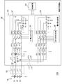
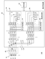
- FIG. 1 is a circuit diagram showing a configuration of a power supply device 100 according to the first embodiment.
- the power supply apparatus 100 can be mounted on a vehicle as a power source such as a hybrid vehicle or an electric vehicle.
- the power supply device 100 includes an assembled battery (power storage module) 10 and a battery management device (management device) 30.
- the assembled battery 10 and the battery management device 30 are connected by a wire harness 20.
- the assembled battery 10 has a plurality of battery cells (cells) connected in series.
- three battery cells S1 to S3 connected in series will be described, and illustration and description of other battery cells are omitted.
- a lithium ion battery is assumed as the type of battery.
- 200V or more is the mainstream, and battery cells are often used in 60 series or more.
- a load and a charging circuit are connected between both ends of the assembled battery 10. The assembled battery 10 is discharged to a load and charged by a charging circuit.
- the battery management device 30 includes a plurality of first capacitor elements C11 to C13, a plurality of first resistors R11 to R14, a plurality of second capacitor elements C21 to C23, a plurality of second resistors R21 to R24, and voltage detection.
- a device 32 and a control circuit 34 are provided. Regarding the battery management device 30 as well, configurations corresponding to the battery cells S1 to S3 will be described, and illustrations and descriptions of configurations corresponding to other battery cells will be omitted.
- the battery management device 30 manages the assembled battery 10.
- the battery management device 30 is configured on a printed wiring board, for example.
- Each node of the plurality of battery cells S1 to S3 and common nodes N1 to N4 in the battery management device 30 are connected by common voltage detection lines L1 to L4, respectively.
- the common nodes N1 to N4 and the plurality of first voltage input terminals VP11 to VP14 of the voltage detection device 32 are connected by first voltage detection lines L11 to L14, respectively.
- the common nodes N1 to N4 and the plurality of second voltage input terminals VP21 to VP24 of the voltage detection device 32 are connected by second voltage detection lines L21 to L24, respectively.
- the first voltage detection lines L11 to L14 and the second voltage detection lines L21 to L24 are connected to the nodes of the plurality of battery cells S1 to S3 via the common voltage detection lines L1 to L4.
- the common voltage detection lines L1 to L4 are configured by printed wiring inside the battery management device 30, and are configured by the wire harness 20 outside the battery management device 30.
- the first voltage detection lines L11 to L14 and the second voltage detection lines L21 to L24 are configured by printed wiring.
- Each of the plurality of first voltage detection lines L11 to L14 is provided with a low pass filter.
- the low-pass filter suppresses noise in the first voltage detection lines L11 to L14.
- the low-pass filter is configured by an RC circuit.
- first resistors R11 to R14 are connected in series to the plurality of first voltage detection lines L11 to L14, respectively.
- the plurality of first capacitance elements C11 to C13 are connected between the two first voltage detection lines connected to the battery cells S1 to S3 on the voltage detection device 32 side from the first resistors R11 to R14. That is, the first capacitive element C11 is connected between the first voltage detection line L11 and the first voltage detection line L12, and the first capacitive element C12 is connected between the first voltage detection line L12 and the first voltage detection line L13. A first capacitive element C13 is connected between the first voltage detection line L13 and the first voltage detection line L14. As described above, the plurality of first capacitor elements C11 to C13 are respectively connected between both ends of the corresponding battery cell.
- Each of the plurality of second voltage detection lines L21 to L24 is provided with a low pass filter.
- the low-pass filter suppresses noise in the second voltage detection lines L21 to L24.
- the second resistors R21 to R24 are connected in series to the plurality of second voltage detection lines L21 to L24, respectively.
- the plurality of second capacitance elements C21 to C23 are connected between the two second voltage detection lines connected to the battery cells S1 to S3, respectively. That is, the second capacitor element C21 is connected between the second voltage detection line L21 and the second voltage detection line L22, and the second capacitor element C22 is connected between the second voltage detection line L22 and the second voltage detection line L23.
- the second capacitive element C23 is connected between the second voltage detection line L23 and the second voltage detection line L24.
- the plurality of second capacitor elements C21 to C23 are respectively connected between both ends of the corresponding battery cell.
- the voltage detection device 32 detects each voltage of the plurality of battery cells S1 to S3. The detected voltages of the battery cells S1 to S3 are transmitted to the control circuit 34.
- the voltage detection device 32 includes an ASIC (Application (Specific Integrated Circuit) that is a dedicated custom IC. Here, the voltage detection device 32 is configured as one semiconductor integrated circuit.
- the voltage detection device 32 includes a first voltage detection circuit 35, a second voltage detection circuit 36, a first charge extraction circuit 37, and a second charge extraction circuit 38.
- the first voltage detection circuit 35 is connected to the first voltage input terminals VP11 to VP14. That is, the first voltage detection circuit 35 is connected to each node of the plurality of battery cells S1 to S3 by the common voltage detection lines L1 to L4 and the first voltage detection lines L11 to L14, and the plurality of battery cells S1 to S3. Each voltage of is detected.
- the second voltage detection circuit 36 is connected to the second voltage input terminals VP21 to VP24. That is, the second voltage detection circuit 36 is connected to each node of the plurality of battery cells S1 to S3 by the common voltage detection lines L1 to L4 and the second voltage detection lines L21 to L24, and the plurality of battery cells S1 to S3. Each voltage of is detected.
- the first charge extraction circuit 37 is connected to the first voltage input terminals VP11 to VP14, and from each node of the plurality of battery cells S1 to S3 via the voltage detection lines L1 to L4 and the first voltage detection lines L11 to L14. Pull out the charge.
- the first charge extraction circuit 37 includes a plurality of first switch elements SW11 to SW14 and a plurality of first current sources I11 to I14. One end of each of the plurality of first switch elements SW11 to SW14 is connected to the corresponding first voltage input terminal.
- Each of the plurality of first current sources I11 to I14 has one end connected to the other end of the corresponding first switch element, the other end connected to the ground potential (predetermined fixed potential), and the corresponding first switch element When conducting, a constant current is drawn from the corresponding first voltage detection line.
- the second charge extracting circuit 38 is connected to the second voltage input terminals VP21 to VP24, and is connected to each node of the plurality of battery cells S1 to S3 via the voltage detection lines L1 to L4 and the second voltage detection lines L21 to L24. Pull out the charge.
- the second charge extracting circuit 38 includes a plurality of second switch elements SW21 to SW24 and a plurality of second current sources I21 to I24. Each of the plurality of second switch elements SW21 to SW24 has one end connected to the corresponding second voltage input terminal.
- Each of the plurality of second current sources I21 to I24 has one end connected to the other end of the corresponding second switch element, the other end connected to the ground potential, and the corresponding second switch element conducting.
- the constant current is drawn from the corresponding second voltage detection line.
- the magnitudes of the constant currents drawn by the first current sources I11 to I14 and the second current sources I21 to I24 are substantially equal to each other.
- the first switch elements SW11 to SW14 and the second switch elements SW21 to SW24 are, for example, N-type MOS transistors.
- the second capacitance elements C21 to C23, the second resistors R21 to R24, the second voltage detection circuit 36, and the second charge extraction circuit 38 constitute a redundant circuit.
- the control circuit 34 controls the first charge extraction circuit 37 and the second charge extraction circuit 38 to detect disconnection. Details of the disconnection detection will be described later. Further, the control circuit 34 refers to the voltage of the battery cells S1 to S3 acquired from the first voltage detection circuit 35 or the second voltage detection circuit 36, and a battery such as cell voltage equalization control (hereinafter referred to as cell balance). Take control. The control circuit 34 notifies the acquired voltage to a higher-level control device (not shown). The host control device performs charge / discharge control of the assembled battery 10 based on the notified voltage.
- control circuit 34 detects an abnormality in each voltage of the battery cells S1 to S3, the control circuit 34 notifies the upper control device of an abnormality detection signal indicating the voltage abnormality.
- the control circuit 34 outputs an abnormality detection signal when the voltage of any of the plurality of battery cells S1 to S3 is lower than the first detection voltage UV and higher than the second detection voltage OV.
- the second detection voltage OV is higher than the first detection voltage UV.
- the control circuit 34 is configured by a CPU, a logic circuit, or a combination thereof.
- the control circuit 34 causes the first charge extraction circuit 37 and the second charge extraction circuit 38 to alternately extract charges. Specifically, the control circuit 34 makes the first switch elements SW11 to SW14 conductive and makes the second switch elements SW21 to SW24 nonconductive, and makes the second switch elements SW21 to SW24 conductive and makes the first switch The state in which the elements SW11 to SW14 are turned off is alternately switched. Thereby, the control circuit 34 can always determine whether a disconnection has occurred while suppressing an increase in power consumption.
- FIG. 2 is a diagram when no disconnection occurs. It is a figure explaining operation
- FIG. 2 shows a state in which the first switch elements SW11 to SW14 are conducting and the first charge extraction circuit 37 is extracting charges.
- the second switch elements SW21 to SW24 are non-conductive.
- a constant current flows through each of the first resistors R11 to R14, and a voltage drop occurs. Since the magnitudes of the constant currents drawn by the first current sources I11 to I14 are substantially equal to each other, the voltage drops of the first resistors R11 to R14 are substantially equal to each other. Accordingly, each voltage detected by the first voltage detection circuit 35 is hardly affected by the voltage drop of the first resistors R11 to R14, and is substantially equal to the voltage of each of the battery cells S1 to S3. That is, the voltage detection error is small.
- the magnitude of the constant current is increased, the voltage can be changed in a shorter time when a disconnection occurs, as will be described later.
- the voltage drop of the first resistors R11 to R14 becomes large, the voltage detection error becomes larger.
- the upper limit value (for example, 4.1 V) of the use voltage of each battery cell S1 to S3 is lower than the second detection voltage OV (for example, 4.5 V) by the margin voltage, and the use voltage of each battery cell S1 to S3
- the lower limit value (for example, 3V) is higher than the first detection voltage UV (for example, 2V) by the margin voltage. Therefore, the magnitude of the constant current is set so that the maximum value of the voltage detection error is smaller than the margin voltage. As a result, the abnormality detection signal can be prevented from being erroneously output by the operations of the first charge extraction circuit 37 and the second charge extraction circuit 38.
- the control circuit 34 acquires the voltage detected by the first voltage detection circuit 35 when the first condition is satisfied.
- the first condition is that the first charge extracting circuit 37 or the second charge extracting circuit 38 extracts the charge, and the voltages of the battery cells S1 to S3 detected by the first voltage detecting circuit 35 and the second voltage detecting circuit 36 are previously set. It is higher than a predetermined threshold voltage Vth. When the first condition is satisfied, no disconnection has occurred. Therefore, the control circuit 34 performs normal control with reference to the acquired voltage.
- FIG. 3 is a diagram for explaining the operation of the power supply apparatus 100 in FIG. 1 when a disconnection occurs in the first voltage detection line L12.
- the first voltage detection line L12 is disconnected due to the disconnection of the first resistor R12.
- the voltage between both ends of the first capacitive element C11 is defined as voltage V11
- the voltage between both ends of the first capacitive element C12 is defined as voltage V12
- the voltage between both ends of the first capacitive element C13 is defined as voltage V13.
- the voltage across the second capacitive element C21 is referred to as voltage V21
- the voltage across the second capacitive element C22 is referred to as voltage V22
- the voltage across the second capacitive element C23 is referred to as voltage V23.
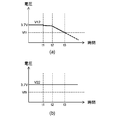
- FIG. 4A is a diagram showing a change in the voltage V12 in FIG. 3, and FIG. 4B is a diagram showing a change in the voltage V22 in FIG.
- a disconnection occurs in the first voltage detection line L12 at time t1, and the first switch elements SW11 to SW14 become conductive at time t2. Since the first voltage detection line L12 is disconnected, the charge of the first capacitive element C12 is extracted by the constant current drawn by the first current source I12. As a result, the voltage V12 starts to decrease as shown in FIG. Further, the voltage V22 does not change as shown in FIG. Although not shown, the other voltages V21 and V23 do not change.
- the control circuit 34 acquires the voltages V21 to V23 detected by the second voltage detection circuit 36, and indicates that one of the first voltage detection lines L11 to L14 is disconnected.
- the first detection signal is notified to the host control device.
- the second condition is that the first charge extraction circuit 37 extracts the charge, the voltage V12 of any battery cell detected by the first voltage detection circuit 35 is equal to or lower than the threshold voltage Vth, and is detected by the second voltage detection circuit 36. That is, the voltage V21 to V23 of each battery cell is higher than the threshold voltage Vth.
- the first detection signal may include which first voltage detection line the disconnection has occurred.
- the control circuit 34 can perform normal control with reference to the acquired voltage. Further, the host control device can perform necessary measures such as limiting the charge / discharge amount of the battery cells S1 to S3 or notifying the user of disconnection according to the first detection signal.
- FIG. 5 is a diagram for explaining the operation of the power supply apparatus 100 in FIG. 1 when a disconnection occurs in the second voltage detection line L22.
- an example is shown in which the second voltage detection line L22 is disconnected due to the disconnection of the second resistor R22.
- FIG. 6A is a diagram showing a change in the voltage V12 in FIG. 5, and FIG. 6B is a diagram showing a change in the voltage V22 in FIG.
- a disconnection occurs in the second voltage detection line L22 at time t4, and the second switch elements SW21 to SW24 are turned on at time t5. Since the second voltage detection line L22 is disconnected, the charge of the second capacitive element C22 is extracted by the constant current drawn by the second current source I22. As a result, the voltage V22 starts to decrease as shown in FIG. Further, the voltage V12 does not change as shown in FIG. Although not shown, other voltages V11 and V13 do not change.
- the control circuit 34 acquires the voltages V11 to V13 detected by the first voltage detection circuit 35 and indicates that one of the second voltage detection lines L21 to L24 is disconnected.
- the second detection signal is notified to the host control device.
- the third condition is that the second charge extraction circuit 38 extracts the charge, the voltage V22 of any battery cell detected by the second voltage detection circuit 36 is equal to or lower than the threshold voltage Vth, and is detected by the first voltage detection circuit 35. That is, the voltage V11 to V13 of each battery cell is higher than the threshold voltage Vth.
- the second detection signal may include which second voltage detection line the disconnection has occurred.
- the control circuit 34 can perform normal control with reference to the acquired voltage. Further, the host control device can perform the above-described response in accordance with the second detection signal.
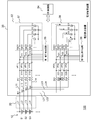
- FIG. 7 is a diagram for explaining the operation of the power supply apparatus 100 of FIG. 1 when a disconnection occurs in the common voltage detection line L2.
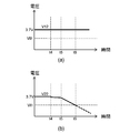
- FIG. 8A is a diagram showing a change in the voltage V12 in FIG. 7
- FIG. 8B is a diagram showing a change in the voltage V22 in FIG.
- a disconnection occurs in the common voltage detection line L2 at time t7, and the first switch elements SW11 to SW14 are turned on at time t8. Since the common voltage detection line L2 is disconnected, the charge of the first capacitive element C12 is pulled out by the constant current drawn by the first current source I12, and the first voltage detection line L12 and the second voltage detection line L22 are connected. Thus, the charge of the second capacitive element C22 is also extracted. As a result, the voltage V12 starts to decrease as shown in FIG. Further, as shown in FIG. 8B, the voltage V22 also starts to decrease.
- the control circuit 34 notifies the host control device of a third detection signal indicating that the common voltage detection lines L1 to L4 are disconnected.
- the fourth condition is that the first charge extraction circuit 37 or the second charge extraction circuit 38 extracts the charge, and the voltage of any battery cell detected by the first voltage detection circuit 35 is equal to or lower than the threshold voltage Vth. That is, the voltage of any battery cell detected by the voltage detection circuit 36 is equal to or lower than the threshold voltage Vth.
- the common detection line for which the disconnection has occurred may be included in the third detection signal.
- the voltage detection device 32 cannot detect the voltages of the battery cells S1 and S2 connected to the common voltage detection line L2. Therefore, the host control device can perform necessary measures such as stopping charging / discharging of the battery cells S1 to S3 and notifying the user of disconnection in accordance with the third detection signal.
- the disconnected first voltage detection line is moved to the high potential side by the first charge extraction circuit 37. Charge is extracted from the connected first capacitor element. As a result, the voltage between both ends of the first capacitive element decreases. Therefore, disconnection of the first voltage detection line can be detected.
- the second charge extraction circuit 38 extracts charges from the second capacitive element connected to the high potential side of the disconnected second voltage detection line. . As a result, the voltage across the second capacitor element decreases. Therefore, disconnection of the second voltage detection line can be detected.
- the battery is detected using the voltage detected by the first voltage detection circuit 35 or the second voltage detection circuit 36 connected to the first voltage detection lines L11 to L14 or the second voltage detection lines L21 to L24 that are not disconnected.
- Charge / discharge control of the cells S1 to S3 can be performed. Therefore, even if a disconnection occurs, the charge / discharge control or the like is not immediately stopped, so that the vehicle can be prevented from being immediately stopped. Therefore, user convenience can be improved.
- the location where the disconnection occurred can be identified. Therefore, it can respond appropriately according to the place where the disconnection occurs.
- the second embodiment differs from the first embodiment in that the second charge extraction circuit is configured using a cell balance switch element. Below, it demonstrates centering around difference with 1st Embodiment.
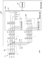
- FIG. 9 is a circuit diagram showing a configuration of a power supply device 100A according to the second embodiment.
- the second charge extraction circuit 38A includes a plurality of second switch elements SW31 to SW33 connected between the two second voltage detection lines connected to the battery cells S1 to S3, respectively.
- the second switch element SW31 is connected between the second voltage input terminal VP21 and the second voltage input terminal VP22.
- the second switch element SW32 is connected between the second voltage input terminal VP22 and the second voltage input terminal VP23.
- the second switch element SW33 is connected between the second voltage input terminal VP23 and the second voltage input terminal VP23.
- the second switch elements SW31 to SW33 are, for example, N-type MOS transistors.
- the second switch elements SW31 to SW33 are also used as cell balance switch elements.
- the control circuit 34 makes the plurality of second switch elements SW31 to SW33 of the second charge extraction circuit 38A conductive and then non-conductive, and any battery cell detected by the second voltage detection circuit 36. Is determined to be equal to or lower than the threshold voltage Vth.
- the charge of the second capacitor element C22 is extracted by the conductive second switch element SW32. As a result, the voltage across the second capacitive element C22 decreases.
- the control circuit 34 makes every other second switch element SW31, SW33 conductive and then non-conductive, and then makes every other second switch element SW32 conductive and make it non-conductive. Is preferred.
- the charge can be extracted by using the second switch elements SW31 to SW33 for cell balance, it is not necessary to provide a current source in the second charge extraction circuit 38A. Therefore, the number of current sources can be reduced to half compared to the first embodiment. Thereby, voltage detection apparatus 32A can be reduced in size.
- the first charge extraction circuit 37 is also connected between the two first voltage detection lines connected to the battery cells S1 to S3 without using a current source.
- a plurality of switch elements may be used. In this configuration, when the size of the current source is relatively large, the voltage detection device 32A can be downsized.
- the voltage detection device 32 of the first embodiment is configured as one semiconductor integrated circuit
- the voltage detection device is divided into two semiconductor integrated circuits. Below, it demonstrates centering around difference with 1st Embodiment.
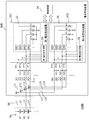
- FIG. 10 is a circuit diagram showing a configuration of a power supply device 100B according to the third embodiment.
- the first voltage detection device 321, that is, the first voltage detection circuit 35 and the first charge extraction circuit 37 are configured as a first semiconductor integrated circuit.
- the second voltage detection device 322, that is, the second voltage detection circuit 36 and the second charge extraction circuit 38 are configured as a second semiconductor integrated circuit.
- the first voltage detection device 321 is the same circuit as the second voltage detection device 322.
- the battery management device 30B can be configured using the same two semiconductor integrated circuits.
- the battery management device 30 can also be applied to use for managing the power storage modules in the stationary power storage system.
- the plurality of battery cells S1 to S3 may be capacitors (capacitors) such as electric double layer capacitors.
- a first voltage detection circuit is connected to each node of a plurality of cells (S1 to S3) connected in series by a first voltage detection line (L11 to L14), and detects a voltage of each of the plurality of cells (S1 to S3).
- a second voltage detection circuit (36) is connected to each node of the plurality of cells (S1 to S3) by a second voltage detection line (L21 to L24) and detects a voltage of each of the plurality of cells (S1 to S3).
- the management device (30, 30) according to item 1, further comprising a control circuit (34) for alternately extracting charges from the first charge extraction circuit (37) and the second charge extraction circuit (38, 38A). 30A, 30B). According to this, it is possible to always determine whether a disconnection has occurred while suppressing an increase in power consumption.
- the control circuit (34) The first charge extraction circuit (37) extracts charges, and the voltage of any of the cells (S1 to S3) detected by the first voltage detection circuit (35) is equal to or lower than a threshold voltage, and the second voltage detection When the voltage of each cell (S1 to S3) detected by the circuit (36) is higher than the threshold voltage, the voltage detected by the second voltage detection circuit (36) is obtained, The second charge extraction circuit (38, 38A) extracts the charge, and the voltage of any one of the cells (S1 to S3) detected by the second voltage detection circuit (36) is equal to or lower than the threshold voltage. When the voltage of each cell (S1 to S3) detected by one voltage detection circuit (35) is higher than the threshold voltage, the voltage detected by the first voltage detection circuit (35) is acquired.
- the management device (30, 30A, 30B) according to item 2. According to this, charging / discharging of the cells (S1 to S3) is performed using the voltage detected via the first voltage detection lines (L11 to L14) or the second voltage detection lines (L21 to L24) that are not disconnected. Control can be performed. [Item 4] In the control circuit (34), the first charge extraction circuit (37) extracts a charge, and the voltage of any one of the cells (S1 to S3) detected by the first voltage detection circuit (35) is less than a threshold voltage. When the voltage of each cell (S1 to S3) detected by the second voltage detection circuit (36) is higher than the threshold voltage, and the second charge extraction circuit (38, 38A) extracts the charge.
- the voltage of any one of the cells (S1 to S3) detected by the second voltage detection circuit (36) is equal to or lower than the threshold voltage, and each cell (S1 detected by the first voltage detection circuit (35)).
- a detection signal indicating that the first voltage detection lines (L11 to L14) or the second voltage detection lines (L21 to L24) are disconnected is output.
- Item 2 or 3 The apparatus according (30,30A, 30B). According to this, when a detection signal indicating that the first voltage detection line (L11 to L14) or the second voltage detection line (L21 to L24) is disconnected is output, the charge / discharge amount of the cells (S1 to S3) Necessary measures such as restriction of the user and notification to the user can be performed.
- the first voltage detection lines (L11 to L14) and the second voltage detection lines (L11 to L14) are connected to each node of the plurality of cells (S1 to S3) via a common voltage detection line (L1 to L4).
- Connected to The control circuit (34) is one of the first charge extraction circuit (37) and the second charge extraction circuit (38, 38A) that has been extracted by the first voltage detection circuit (35).
- the common 5 When the voltage of the cells (S1 to S3) is lower than the threshold voltage and the voltage of any of the cells (S1 to S3) detected by the second voltage detection circuit (36) is lower than the threshold voltage, the common 5.
- the management device (30, 30A, 30B) according to any one of items 2 to 4, wherein a detection signal indicating that the voltage detection lines (L1 to L4) are disconnected is output. According to this, when a detection signal indicating that the common voltage detection lines (L1 to L4) are disconnected is output, it is necessary to stop charging / discharging of the cells (S1 to S3) or to notify the user. Action can be taken.
- the first charge extraction circuit (37) includes: A plurality of first switch elements (SW11 to SW14) each having one end connected to a corresponding first voltage detection line (L11 to L14); A plurality of first current sources (I11 to I14) each having one end connected to the other end of the corresponding first switch element (SW11 to SW14) and the other end connected to a predetermined fixed potential; And
- the second charge extraction circuit (38) includes: A plurality of second switch elements (SW21 to SW24) each having one end connected to a corresponding second voltage detection line (L21 to L24); A plurality of second current sources (I21 to I24) each having one end connected to the other end of the corresponding second switch element (SW21 to SW24) and the other end connected to the fixed potential;
- the management device (30, 30B) according to any one of items 1 to 5, characterized by: According to this, the first charge extraction circuit (37) and the second charge extraction circuit (38) can be realized with a simple configuration.
- the first charge extraction circuit (37) includes: A plurality of first switch elements (SW11 to SW14) each having one end connected to a corresponding first voltage detection line (L11 to L14); A plurality of first current sources (I11 to I14) each having one end connected to the other end of the corresponding first switch element (SW11 to SW14) and the other end connected to a predetermined fixed potential; And
- the second charge extraction circuit (38A) includes a plurality of second voltage detection lines (L21 and L22, L22 and L23, L23 and L24) connected to the cells (S1 to S3), respectively. 6.
- the management device (30A) according to any one of items 1 to 5, wherein the management device (30A) includes the second switch elements (SW31 to SW33).
- the first voltage detection circuit (35) and the first charge extraction circuit (37) are configured as a first semiconductor integrated circuit (321), Any one of items 1 to 6, wherein the second voltage detection circuit (36) and the second charge extraction circuit (38) are configured as a second semiconductor integrated circuit (322).
- the management device (30, 30A, 30B) according to any one of items 1 to 8 for managing the power storage module (10);
- a power supply device (100, 100A, 100B) comprising:
Landscapes
- Engineering & Computer Science (AREA)
- General Physics & Mathematics (AREA)
- Physics & Mathematics (AREA)
- Power Engineering (AREA)
- Chemical & Material Sciences (AREA)
- Chemical Kinetics & Catalysis (AREA)
- Electrochemistry (AREA)
- General Chemical & Material Sciences (AREA)
- Manufacturing & Machinery (AREA)
- Microelectronics & Electronic Packaging (AREA)
- Sustainable Development (AREA)
- Life Sciences & Earth Sciences (AREA)
- Sustainable Energy (AREA)
- Transportation (AREA)
- Mechanical Engineering (AREA)
- Charge And Discharge Circuits For Batteries Or The Like (AREA)
- Secondary Cells (AREA)
- Testing Of Short-Circuits, Discontinuities, Leakage, Or Incorrect Line Connections (AREA)
- Tests Of Electric Status Of Batteries (AREA)
Abstract
断線検出できると共に、断線が発生した場所を特定できる技術を提供するために、第1電圧検出回路(35)は、直列接続された複数のセル(S1~S3)の各ノードに第1電圧検出線(L11~L14)で接続され、当該複数のセルのそれぞれの電圧を検出する。第2電圧検出回路(36)は、複数のセル(S1~S3)の各ノードに第2電圧検出線(L21~L24)で接続され、当該複数のセルのそれぞれの電圧を検出する。第1容量素子(C11~C13)は、各セルに接続された2本の第1電圧検出線間にそれぞれ接続される。第2容量素子(C21~C23)は、各セルに接続された2本の第2電圧検出線間にそれぞれ接続される。第1電荷引き抜き回路(37)は、複数のセル(S1~S3)の各ノードから各第1電圧検出線(L11~L14)を介して電荷を引き抜く。第2電荷引き抜き回路(38)は、複数のセル(S1~S3)の各ノードから各第2電圧検出線(L21~L24)を介して電荷を引き抜く。
Description
本発明は、電池などの蓄電モジュールの状態を管理する管理装置、および、その管理装置を備える電源装置に関する。
近年、ハイブリッド車(HV)、プラグインハイブリッド車(PHV)、電気自動車(EV)が普及してきている。これらの車にはキーデバイスとして二次電池が搭載される。車載用二次電池としては主に、ニッケル水素電池およびリチウムイオン電池が普及している。今後、エネルギー密度が高いリチウムイオン電池の普及が加速すると予想される。
リチウムイオン電池は常用領域と使用禁止領域が近接しているため、他の種類の電池より厳格な電圧管理が必要である。複数のリチウムイオン電池セルが直列に接続された組電池を使用する場合、各電池セルの電圧を検出するための電圧検出回路が設けられる。各電池セルと電圧検出回路は、電圧検出線で接続される。検出される各電池セルの電圧は、充放電制御およびセル電圧の均等化制御などに使用される。
電圧検出回路の故障を判定するため、冗長回路として別の電圧検出回路が設けられる技術も知られている。電圧検出回路により検出された電圧と、冗長回路により検出された電圧とに一定以上の差がある場合、故障が生じていると判定し、車両を停止させる。このような技術に関連して、特許文献1に記載の技術も知られている。
しかし、従来の技術では、故障が生じていることは判定できるが、電圧検出線が断線しているか否か判定することは困難である。
本発明はこうした状況に鑑みなされたものであり、その目的は、断線検出できると共に、断線が発生した場所を特定できる技術を提供することにある。
上記課題を解決するために、本発明のある態様の管理装置は、直列接続された複数のセルの各ノードに第1電圧検出線で接続され、当該複数のセルのそれぞれの電圧を検出する第1電圧検出回路と、前記複数のセルの各ノードに第2電圧検出線で接続され、当該複数のセルのそれぞれの電圧を検出する第2電圧検出回路と、各セルに接続された2本の第1電圧検出線間にそれぞれ接続された複数の第1容量素子と、各セルに接続された2本の第2電圧検出線間にそれぞれ接続された複数の第2容量素子と、前記複数のセルの各ノードから各第1電圧検出線を介して電荷を引き抜く第1電荷引き抜き回路と、前記複数のセルの各ノードから各第2電圧検出線を介して電荷を引き抜く第2電荷引き抜き回路と、を備える。
本発明によれば、断線検出できると共に、断線が発生した場所を特定できる。
(第1の実施形態)
図1は、第1の実施形態に係る電源装置100の構成を示す回路図である。電源装置100は、例えば、ハイブリッド車、電気自動車などの動力源として車両に搭載することができる。電源装置100は、組電池(蓄電モジュール)10および電池管理装置(管理装置)30を備える。組電池10と電池管理装置30間はワイヤーハーネス20により接続される。
図1は、第1の実施形態に係る電源装置100の構成を示す回路図である。電源装置100は、例えば、ハイブリッド車、電気自動車などの動力源として車両に搭載することができる。電源装置100は、組電池(蓄電モジュール)10および電池管理装置(管理装置)30を備える。組電池10と電池管理装置30間はワイヤーハーネス20により接続される。
組電池10は直列接続された複数の電池セル(セル)を有する。本実施形態では、直列接続された3つの電池セルS1~S3について説明し、他の電池セルは図示および説明を省略する。また電池の種別としてリチウムイオン電池を想定する。ハイブリッド車や電気自動車に搭載される組電池10は200V以上が主流であり、電池セルは60直列以上で使用されることが多い。組電池10の両端間には、図示を省略した負荷および充電回路が接続される。組電池10は、負荷に放電し、また、充電回路によって充電される。
電池管理装置30は、複数の第1容量素子C11~C13と、複数の第1抵抗R11~R14と、複数の第2容量素子C21~C23と、複数の第2抵抗R21~R24と、電圧検出装置32と、制御回路34とを備える。電池管理装置30に関しても、電池セルS1~S3に対応する構成について説明し、他の電池セルに対応する構成は図示および説明を省略する。電池管理装置30は組電池10を管理する。電池管理装置30は、例えばプリント配線基板上に構成される。
複数の電池セルS1~S3の各ノードと、電池管理装置30内の共通ノードN1~N4はそれぞれ共通の電圧検出線L1~L4で接続される。共通ノードN1~N4と、電圧検出装置32の複数の第1電圧入力端子VP11~VP14はそれぞれ第1電圧検出線L11~L14で接続される。共通ノードN1~N4と、電圧検出装置32の複数の第2電圧入力端子VP21~VP24はそれぞれ第2電圧検出線L21~L24で接続される。このように、第1電圧検出線L11~L14と第2電圧検出線L21~L24は、共通の電圧検出線L1~L4を介して複数の電池セルS1~S3の各ノードに接続される。
共通の電圧検出線L1~L4は、電池管理装置30の内部ではプリント配線で構成され、電池管理装置30の外部ではワイヤーハーネス20で構成される。第1電圧検出線L11~L14と第2電圧検出線L21~L24は、プリント配線で構成される。
複数の第1電圧検出線L11~L14には、それぞれローパスフィルタが設けられる。ローパスフィルタは、第1電圧検出線L11~L14のノイズを抑制する。図1に示す例ではローパスフィルタをRC回路で構成している。具体的には、複数の第1電圧検出線L11~L14にそれぞれ第1抵抗R11~R14が直列に接続される。
第1抵抗R11~R14より電圧検出装置32側において、複数の第1容量素子C11~C13は、各電池セルS1~S3に接続された2本の第1電圧検出線間にそれぞれ接続される。つまり、第1電圧検出線L11と第1電圧検出線L12間に第1容量素子C11が接続され、第1電圧検出線L12と第1電圧検出線L13間に第1容量素子C12が接続され、第1電圧検出線L13と第1電圧検出線L14間に第1容量素子C13が接続される。このように複数の第1容量素子C11~C13は、対応する電池セルの両端間にそれぞれ接続される。
複数の第2電圧検出線L21~L24には、それぞれローパスフィルタが設けられる。ローパスフィルタは、第2電圧検出線L21~L24のノイズを抑制する。具体的には、複数の第2電圧検出線L21~L24にそれぞれ第2抵抗R21~R24が直列に接続される。
第2抵抗R21~R24より電圧検出装置32側において、複数の第2容量素子C21~C23は、各電池セルS1~S3に接続された2本の第2電圧検出線間にそれぞれ接続される。つまり、第2電圧検出線L21と第2電圧検出線L22間に第2容量素子C21が接続され、第2電圧検出線L22と第2電圧検出線L23間に第2容量素子C22が接続され、第2電圧検出線L23と第2電圧検出線L24間に第2容量素子C23が接続される。このように複数の第2容量素子C21~C23は、対応する電池セルの両端間にそれぞれ接続される。
電圧検出装置32は、複数の電池セルS1~S3のそれぞれの電圧を検出する。検出された電池セルS1~S3の各電圧は制御回路34に伝達される。電圧検出装置32は、専用のカスタムICであるASIC(Application Specific Integrated Circuit)等により構成される。ここでは、電圧検出装置32は1つの半導体集積回路として構成される。
電圧検出装置32は、第1電圧検出回路35と、第2電圧検出回路36と、第1電荷引き抜き回路37と、第2電荷引き抜き回路38とを有する。
第1電圧検出回路35は、第1電圧入力端子VP11~VP14に接続される。即ち、第1電圧検出回路35は、複数の電池セルS1~S3の各ノードに共通の電圧検出線L1~L4および第1電圧検出線L11~L14で接続され、当該複数の電池セルS1~S3のそれぞれの電圧を検出する。
第2電圧検出回路36は、第2電圧入力端子VP21~VP24に接続される。即ち、第2電圧検出回路36は、複数の電池セルS1~S3の各ノードに共通の電圧検出線L1~L4および第2電圧検出線L21~L24で接続され、当該複数の電池セルS1~S3のそれぞれの電圧を検出する。
第1電荷引き抜き回路37は、第1電圧入力端子VP11~VP14に接続され、複数の電池セルS1~S3の各ノードから各電圧検出線L1~L4および各第1電圧検出線L11~L14を介して電荷を引き抜く。
第1電荷引き抜き回路37は、複数の第1スイッチ素子SW11~SW14と、複数の第1電流源I11~I14とを含む。複数の第1スイッチ素子SW11~SW14は、それぞれ、一端が対応する第1電圧入力端子に接続される。
複数の第1電流源I11~I14は、それぞれ、一端が対応する第1スイッチ素子の他端に接続され、他端が接地電位(所定の固定電位)に接続され、対応する第1スイッチ素子が導通している場合に、対応する第1電圧検出線から定電流を引き込む。
第2電荷引き抜き回路38は、第2電圧入力端子VP21~VP24に接続され、複数の電池セルS1~S3の各ノードから各電圧検出線L1~L4および各第2電圧検出線L21~L24を介して電荷を引き抜く。
第2電荷引き抜き回路38は、複数の第2スイッチ素子SW21~SW24と、複数の第2電流源I21~I24とを含む。複数の第2スイッチ素子SW21~SW24は、それぞれ、一端が対応する第2電圧入力端子に接続される。
複数の第2電流源I21~I24は、それぞれ、一端が対応する第2スイッチ素子の他端に接続され、他端が接地電位に接続され、対応する第2スイッチ素子が導通している場合に、対応する第2電圧検出線から定電流を引き込む。
第1電流源I11~I14および第2電流源I21~I24が引き込む定電流の大きさは、それぞれ実質的に等しい。第1スイッチ素子SW11~SW14と第2スイッチ素子SW21~SW24は、例えばN型MOSトランジスタである。
第2容量素子C21~C23と、第2抵抗R21~R24と、第2電圧検出回路36と、第2電荷引き抜き回路38は、冗長回路を構成している。
制御回路34は、第1電荷引き抜き回路37と第2電荷引き抜き回路38を制御し、断線検出を行う。断線検出の詳細については後述する。また制御回路34は、第1電圧検出回路35または第2電圧検出回路36から取得した電池セルS1~S3の電圧を参照してセル電圧の均等化制御(以下ではセルバランスと称す)などの電池制御を行う。また制御回路34は、取得した電圧を図示しない上位の制御装置に通知する。上位の制御装置は、通知された電圧に基づいて組電池10の充放電制御を行う。
また制御回路34は、電池セルS1~S3の各電圧の異常を検出すると、電圧の異常を示す異常検知信号を上位の制御装置に通知する。上位の制御装置は、異常検知信号が通知されると、組電池10の充放電を停止させるなどの必要な対応を行う。具体的には制御回路34は、複数の電池セルS1~S3のいずれかの電圧が、第1検出電圧UVより低い場合、および、第2検出電圧OVより高い場合、異常検知信号を出力する。第2検出電圧OVは、第1検出電圧UVより高い。制御回路34は、CPUもしくはロジック回路、またはそれらの組み合わせで構成される。
次に、電源装置100の断線検出について説明する。制御回路34は、第1電荷引き抜き回路37と第2電荷引き抜き回路38に交互に電荷を引き抜かせる。具体的には制御回路34は、第1スイッチ素子SW11~SW14を導通させて第2スイッチ素子SW21~SW24を非導通にさせた状態と、第2スイッチ素子SW21~SW24を導通させて第1スイッチ素子SW11~SW14を非導通にさせた状態とを交互に切り替える。これにより制御回路34は、消費電力の増加を抑制しつつ、断線が発生しているか常時判定することができる。
(1)第1電圧検出線L11~L14、第2電圧検出線L21~L24および共通の電圧検出線L1~L4に断線が発生していない場合
図2は、断線が発生していない場合の図1の電源装置100の動作を説明する図である。図2では、第1スイッチ素子SW11~SW14が導通し、第1電荷引き抜き回路37が電荷を引き抜いている状態を示している。第2スイッチ素子SW21~SW24は非導通である。第1抵抗R11~R14のそれぞれには、定電流が流れ、電圧降下が発生する。第1電流源I11~I14が引き込む定電流の大きさはそれぞれ実質的に等しいため、第1抵抗R11~R14の電圧降下はそれぞれ実質的に等しい。従って、第1電圧検出回路35が検出する各電圧は、第1抵抗R11~R14の電圧降下の影響を受けにくく、電池セルS1~S3のそれぞれの電圧と略等しい。即ち、電圧検出誤差が小さい。
図2は、断線が発生していない場合の図1の電源装置100の動作を説明する図である。図2では、第1スイッチ素子SW11~SW14が導通し、第1電荷引き抜き回路37が電荷を引き抜いている状態を示している。第2スイッチ素子SW21~SW24は非導通である。第1抵抗R11~R14のそれぞれには、定電流が流れ、電圧降下が発生する。第1電流源I11~I14が引き込む定電流の大きさはそれぞれ実質的に等しいため、第1抵抗R11~R14の電圧降下はそれぞれ実質的に等しい。従って、第1電圧検出回路35が検出する各電圧は、第1抵抗R11~R14の電圧降下の影響を受けにくく、電池セルS1~S3のそれぞれの電圧と略等しい。即ち、電圧検出誤差が小さい。
定電流の大きさを大きくするほど、後述のように、断線が発生した場合により短時間で電圧を変化させることができる。しかし、第1抵抗R11~R14の電圧降下が大きくなるため、電圧検出誤差がより大きくなる。ここで、各電池セルS1~S3の使用電圧の上限値(例えば4.1V)はマージン電圧分だけ第2検出電圧OV(例えば4.5V)より低く、各電池セルS1~S3の使用電圧の下限値(例えば3V)はマージン電圧分だけ第1検出電圧UV(例えば2V)より高い。そこで、電圧検出誤差の最大値がマージン電圧より小さくなるように定電流の大きさは設定される。これにより、第1電荷引き抜き回路37と第2電荷引き抜き回路38の動作によって異常検知信号が誤って出力されないようにできる。
第2電荷引き抜き回路38が電荷を引き抜いている状態でも同様に動作する。第2電圧検出回路36が検出する各電圧は、第2抵抗R21~R24の電圧降下の影響を受けにくい。
制御回路34は、第1条件が満たされた場合、第1電圧検出回路35で検出された電圧を取得する。第1条件は、第1電荷引き抜き回路37または第2電荷引き抜き回路38が電荷を引き抜き、第1電圧検出回路35および第2電圧検出回路36で検出された各電池セルS1~S3の電圧が予め定められた閾値電圧Vthより高いことである。第1の条件が満たされた場合、断線は発生していない。そのため制御回路34は、取得した電圧を参照して通常の制御を行う。
(2)第1電圧検出線L11~L14に断線が発生した場合
図3は、第1電圧検出線L12に断線が発生した場合の図1の電源装置100の動作を説明する図である。ここでは、第1抵抗R12が外れたことにより、第1電圧検出線L12が断線している一例を示す。第1容量素子C11の両端間の電圧を電圧V11とし、第1容量素子C12の両端間の電圧を電圧V12とし、第1容量素子C13の両端間の電圧を電圧V13とする。第2容量素子C21の両端間の電圧を電圧V21とし、第2容量素子C22の両端間の電圧を電圧V22とし、第2容量素子C23の両端間の電圧を電圧V23とする。
図3は、第1電圧検出線L12に断線が発生した場合の図1の電源装置100の動作を説明する図である。ここでは、第1抵抗R12が外れたことにより、第1電圧検出線L12が断線している一例を示す。第1容量素子C11の両端間の電圧を電圧V11とし、第1容量素子C12の両端間の電圧を電圧V12とし、第1容量素子C13の両端間の電圧を電圧V13とする。第2容量素子C21の両端間の電圧を電圧V21とし、第2容量素子C22の両端間の電圧を電圧V22とし、第2容量素子C23の両端間の電圧を電圧V23とする。
図4(a)は、図3における電圧V12の変化を示す図であり、図4(b)は、図3における電圧V22の変化を示す図である。時刻t1において第1電圧検出線L12に断線が発生し、時刻t2において第1スイッチ素子SW11~SW14が導通する。第1電圧検出線L12が断線しているため、第1電流源I12が引き込む定電流により、第1容量素子C12の電荷が引き抜かれる。これにより、図4(a)に示すように電圧V12は低下し始める。また、図4(b)に示すように電圧V22は変化しない。図示は省略するが、他の電圧V21,V23も変化しない。
次に、時刻t3において、電圧V12は閾値電圧Vthに達する。制御回路34は、第2条件が満たされた場合、第2電圧検出回路36で検出された電圧V21~V23を取得すると共に、第1電圧検出線L11~L14のいずれかが断線したことを示す第1検出信号を上位の制御装置に通知する。第2条件は、第1電荷引き抜き回路37が電荷を引き抜き、第1電圧検出回路35で検出された何れかの電池セルの電圧V12が閾値電圧Vth以下であり、第2電圧検出回路36で検出された各電池セルの電圧V21~V23が閾値電圧Vthより高いことである。どの第1電圧検出線に断線が発生したかを第1検出信号に含めてもよい。
第2電圧検出回路36で検出された電圧V21~V23は正しい電圧であるため、制御回路34は、取得した電圧を参照して通常の制御を行うことができる。また、上位の制御装置は、第1検出信号に応じて、電池セルS1~S3の充放電量を制限したり、ユーザに断線を通知したりするなどの必要な対応を行うことができる。
(3)第2電圧検出線L21~L24に断線が発生した場合
図5は、第2電圧検出線L22に断線が発生した場合の図1の電源装置100の動作を説明する図である。ここでは、第2抵抗R22が外れたことにより、第2電圧検出線L22が断線している一例を示す。
図5は、第2電圧検出線L22に断線が発生した場合の図1の電源装置100の動作を説明する図である。ここでは、第2抵抗R22が外れたことにより、第2電圧検出線L22が断線している一例を示す。
図6(a)は、図5における電圧V12の変化を示す図であり、図6(b)は、図5における電圧V22の変化を示す図である。時刻t4において第2電圧検出線L22に断線が発生し、時刻t5において第2スイッチ素子SW21~SW24が導通する。第2電圧検出線L22が断線しているため、第2電流源I22が引き込む定電流により、第2容量素子C22の電荷が引き抜かれる。これにより、図6(b)に示すように電圧V22は低下し始める。また、図6(a)に示すように電圧V12は変化しない。図示は省略するが、他の電圧V11,V13も変化しない。
次に、時刻t6において、電圧V22は閾値電圧Vthに達する。制御回路34は、第3条件が満たされた場合、第1電圧検出回路35で検出された電圧V11~V13を取得すると共に、第2電圧検出線L21~L24のいずれかが断線したことを示す第2検出信号を上位の制御装置に通知する。第3条件は、第2電荷引き抜き回路38が電荷を引き抜き、第2電圧検出回路36で検出された何れかの電池セルの電圧V22が閾値電圧Vth以下であり、第1電圧検出回路35で検出された各電池セルの電圧V11~V13が閾値電圧Vthより高いことである。どの第2電圧検出線に断線が発生したかを第2検出信号に含めてもよい。
第1電圧検出回路35で検出された電圧V11~V13は正しい電圧であるため、制御回路34は、取得した電圧を参照して通常の制御を行うことができる。また、上位の制御装置は、第2検出信号に応じて、前述した対応を行うことができる。
(4)共通の電圧検出線L1~L4に断線が発生した場合
図7は、共通の電圧検出線L2に断線が発生した場合の図1の電源装置100の動作を説明する図である。
図8(a)は、図7における電圧V12の変化を示す図であり、図8(b)は、図7における電圧V22の変化を示す図である。時刻t7において共通の電圧検出線L2に断線が発生し、時刻t8において第1スイッチ素子SW11~SW14が導通する。共通の電圧検出線L2が断線しているため、第1電流源I12が引き込む定電流により、第1容量素子C12の電荷が引き抜かれると共に、第1電圧検出線L12および第2電圧検出線L22を介して第2容量素子C22の電荷も引き抜かれる。これにより、図8(a)に示すように電圧V12は低下し始める。また図8(b)に示すように電圧V22も低下し始める。
次に、時刻t9において、電圧V12及び電圧V22は閾値電圧Vthに達する。制御回路34は、第4条件が満たされた場合、共通の電圧検出線L1~L4が断線したことを示す第3検出信号を上位の制御装置に通知する。第4条件は、第1電荷引き抜き回路37または第2電荷引き抜き回路38が電荷を引き抜き、第1電圧検出回路35で検出された何れかの電池セルの電圧が閾値電圧Vth以下であり、第2電圧検出回路36で検出された何れかの電池セルの電圧が閾値電圧Vth以下であることである。どの共通の電圧検出線に断線が発生したかを第3検出信号に含めてもよい。
電圧検出装置32は、共通の電圧検出線L2に接続された電池セルS1,S2の電圧を検出できない。そのため、上位の制御装置は、第3検出信号に応じて、電池セルS1~S3の充放電を停止すると共に、ユーザに断線を通知するなどの必要な対応を行うことができる。
以上で説明したように、本実施形態によれば、第1電圧検出線L11~L14のいずれかが断線した場合、第1電荷引き抜き回路37によって、断線した第1電圧検出線が高電位側に接続された第1容量素子から電荷が引き抜かれる。これにより、当該第1容量素子の両端間の電圧は低下する。よって、第1電圧検出線の断線を検出できる。
また、第2電圧検出線L21~L24のいずれかが断線した場合、第2電荷引き抜き回路38によって、断線した第2電圧検出線が高電位側に接続された第2容量素子から電荷が引き抜かれる。これにより、当該第2容量素子の両端間の電圧は低下する。よって、第2電圧検出線の断線を検出できる。
そのため、断線していない第1電圧検出線L11~L14または第2電圧検出線L21~L24に接続された第1電圧検出回路35または第2電圧検出回路36で検出された電圧を用いて、電池セルS1~S3の充放電制御などを行うことができる。よって、断線が発生しても、すぐに充放電制御などを停止させないため、すぐに車両を停止させないようにできる。従って、ユーザの利便性を高めることができる。
さらに、共通の電圧検出線L1~L4のいずれかが断線した場合、第2電荷引き抜き回路38によって、断線した共通の電圧検出線が高電位側に接続された第1容量素子および第2容量素子から電荷が引き抜かれる。これにより、当該第1容量素子および第2容量素子のそれぞれの両端間の電圧は低下する。よって、共通の電圧検出線の断線を検出できる。
このように、断線が発生した場所を特定できる。そのため、断線が発生した場所に応じて、適切に対応することができる。
(第2の実施形態)
第2の実施形態では、第2電荷引き抜き回路はセルバランス用のスイッチ素子を用いて構成されている点において第1の実施形態と異なる。以下では、第1の実施形態との相違点を中心に説明する。
第2の実施形態では、第2電荷引き抜き回路はセルバランス用のスイッチ素子を用いて構成されている点において第1の実施形態と異なる。以下では、第1の実施形態との相違点を中心に説明する。
図9は、第2の実施形態に係る電源装置100Aの構成を示す回路図である。第2電荷引き抜き回路38Aは、各電池セルS1~S3に接続された2本の第2電圧検出線間にそれぞれ接続された複数の第2スイッチ素子SW31~SW33を有する。具体的には、第2スイッチ素子SW31は第2電圧入力端子VP21と第2電圧入力端子VP22間に接続される。第2スイッチ素子SW32は第2電圧入力端子VP22と第2電圧入力端子VP23間に接続される。第2スイッチ素子SW33は第2電圧入力端子VP23と第2電圧入力端子VP23間に接続される。第2スイッチ素子SW31~SW33は、例えばN型MOSトランジスタである。
また、第2スイッチ素子SW31~SW33は、セルバランス用のスイッチ素子としても用いられる。
また、第2スイッチ素子SW31~SW33は、セルバランス用のスイッチ素子としても用いられる。
制御回路34は、断線検出時に、第2電荷引き抜き回路38Aの複数の第2スイッチ素子SW31~SW33を導通させてから非導通にさせ、第2電圧検出回路36で検出された何れかの電池セルの電圧が閾値電圧Vth以下か否か判定する。
第1の実施形態と同様に、例えば第2電圧検出線L22が断線している場合、導通した第2スイッチ素子SW32により、第2容量素子C22の電荷が引き抜かれる。これにより、第2容量素子C22の両端間の電圧は低下する。
制御回路34は、1つおきの第2スイッチ素子SW31,SW33を導通させてから非導通にさせ、次に、残りの1つおきの第2スイッチ素子SW32を導通させてから非導通にさせることが好ましい。
本実施形態によれば、セルバランス用の第2スイッチ素子SW31~SW33を用いて電荷を引き抜くことができるので、第2電荷引き抜き回路38Aに電流源を設ける必要がない。よって、第1の実施形態と比較して電流源の数を半分に減らすことができる。これにより、電圧検出装置32Aを小型化することができる。
なお、第2電荷引き抜き回路38Aと同様に、第1電荷引き抜き回路37も、電流源を用いず、各電池セルS1~S3に接続された2本の第1電圧検出線間にそれぞれ接続された複数のスイッチ素子で構成してもよい。この構成では、電流源のサイズが比較的大きい場合、電圧検出装置32Aを小型化することができる。
(第3の実施形態)
第1の実施形態の電圧検出装置32は1つの半導体集積回路として構成されるが、第2の実施形態では電圧検出装置を2つの半導体集積回路に分ける。以下では、第1の実施形態との相違点を中心に説明する。
第1の実施形態の電圧検出装置32は1つの半導体集積回路として構成されるが、第2の実施形態では電圧検出装置を2つの半導体集積回路に分ける。以下では、第1の実施形態との相違点を中心に説明する。
図10は、第3の実施形態に係る電源装置100Bの構成を示す回路図である。図10に示すように、第1電圧検出装置321、即ち第1電圧検出回路35と第1電荷引き抜き回路37は、第1の半導体集積回路として構成される。第2電圧検出装置322、即ち第2電圧検出回路36と第2電荷引き抜き回路38は、第2の半導体集積回路として構成される。第1電圧検出装置321は、第2電圧検出装置322と同一の回路である。
本実施形態によれば、同一の2つの半導体集積回路を用いて電池管理装置30Bを構成することができる。
以上、本発明を実施形態をもとに説明した。これら実施形態は例示であり、それらの各構成要素や各処理プロセスの組合せにいろいろな変形例が可能なこと、またそうした変形例も本発明の範囲にあることは当業者に理解されるところである。
上述の実施の形態では電池管理装置30を車載用二次電池を管理するために使用する例を説明した。この点、電池管理装置30は据置型の蓄電システム内の蓄電モジュールを管理する用途にも適用可能である。また、複数の電池セルS1~S3は、電気二重層コンデンサ等のコンデンサ(キャパシタ)であってもよい。
なお、実施の形態は、以下の項目によって特定されてもよい。
[項目1]
直列接続された複数のセル(S1~S3)の各ノードに第1電圧検出線(L11~L14)で接続され、当該複数のセル(S1~S3)のそれぞれの電圧を検出する第1電圧検出回路(35)と、
前記複数のセル(S1~S3)の各ノードに第2電圧検出線(L21~L24)で接続され、当該複数のセル(S1~S3)のそれぞれの電圧を検出する第2電圧検出回路(36)と、
各セル(S1~S3)に接続された2本の第1電圧検出線(L11とL12、L12とL13、L13とL14)間にそれぞれ接続された複数の第1容量素子(C11~C13)と、
各セル(S1~S3)に接続された2本の第2電圧検出線(L21とL22、L22とL23、L23とL24)間にそれぞれ接続された複数の第2容量素子(C21~C23)と、
前記複数のセル(S1~S3)の各ノードから各第1電圧検出線(L11~L14)を介して電荷を引き抜く第1電荷引き抜き回路(37)と、
前記複数のセル(S1~S3)の各ノードから各第2電圧検出線(L21~L24)を介して電荷を引き抜く第2電荷引き抜き回路(38、38A)と、
を備えることを特徴とする管理装置(30、30A、30B)。
これによれば、断線検出できると共に、断線が発生した場所を特定できる。
[項目2]
前記第1電荷引き抜き回路(37)と前記第2電荷引き抜き回路(38,38A)に交互に電荷を引き抜かせる制御回路(34)を備えることを特徴とする項目1に記載の管理装置(30、30A、30B)。
これによれば、消費電力の増加を抑制しつつ、断線が発生しているか常時判定することができる。
[項目3]
前記制御回路(34)は、
前記第1電荷引き抜き回路(37)が電荷を引き抜き、前記第1電圧検出回路(35)で検出された何れかのセル(S1~S3)の電圧が閾値電圧以下であり、前記第2電圧検出回路(36)で検出された各セル(S1~S3)の電圧が前記閾値電圧より高い場合、前記第2電圧検出回路(36)で検出された電圧を取得し、
前記第2電荷引き抜き回路(38、38A)が電荷を引き抜き、前記第2電圧検出回路(36)で検出された何れかのセル(S1~S3)の電圧が前記閾値電圧以下であり、前記第1電圧検出回路(35)で検出された各セル(S1~S3)の電圧が前記閾値電圧より高い場合、前記第1電圧検出回路(35)で検出された電圧を取得することを特徴とする項目2に記載の管理装置(30、30A、30B)。
これによれば、断線していない第1電圧検出線(L11~L14)または第2電圧検出線(L21~L24)を介して検出された電圧を用いて、セル(S1~S3)の充放電制御などを行うことができる。
[項目4]
前記制御回路(34)は、前記第1電荷引き抜き回路(37)が電荷を引き抜き、前記第1電圧検出回路(35)で検出された何れかのセル(S1~S3)の電圧が閾値電圧以下であり、前記第2電圧検出回路(36)で検出された各セル(S1~S3)の電圧が前記閾値電圧より高い場合、および、前記第2電荷引き抜き回路(38、38A)が電荷を引き抜き、前記第2電圧検出回路(36)で検出された何れかのセル(S1~S3)の電圧が前記閾値電圧以下であり、前記第1電圧検出回路(35)で検出された各セル(S1~S3)の電圧が前記閾値電圧より高い場合、前記第1電圧検出線(L11~L14)または前記第2電圧検出線(L21~L24)が断線したことを示す検出信号を出力することを特徴とする項目2または3に記載の管理装置(30、30A、30B)。
これによれば、第1電圧検出線(L11~L14)または第2電圧検出線(L21~L24)が断線したことを示す検出信号が出力された場合、セル(S1~S3)の充放電量の制限や、ユーザへの通知などの必要な対応を行うことができる。
[項目5]
前記第1電圧検出線(L11~L14)と前記第2電圧検出線(L11~L14)は、共通の電圧検出線(L1~L4)を介して前記複数のセル(S1~S3)の各ノードに接続され、
前記制御回路(34)は、前記第1電荷引き抜き回路(37)または前記第2電荷引き抜き回路(38、38A)が電荷を引き抜き、前記第1電圧検出回路(35)で検出された何れかのセル(S1~S3)の電圧が閾値電圧以下であり、前記第2電圧検出回路(36)で検出された何れかのセル(S1~S3)の電圧が前記閾値電圧以下である場合、前記共通の電圧検出線(L1~L4)が断線したことを示す検出信号を出力することを特徴とする項目2から4のいずれか1項に記載の管理装置(30、30A、30B)。
これによれば、共通の電圧検出線(L1~L4)が断線したことを示す検出信号が出力された場合、セル(S1~S3)の充放電の停止や、ユーザへの通知などの必要な対応を行うことができる。
[項目6]
前記第1電荷引き抜き回路(37)は、
対応する第1電圧検出線(L11~L14)に接続された一端をそれぞれ有する複数の第1スイッチ素子(SW11~SW14)と、
対応する第1スイッチ素子(SW11~SW14)の他端に接続された一端と、所定の固定電位に接続された他端とをそれぞれ有する複数の第1電流源(I11~I14)と、を有し、
前記第2電荷引き抜き回路(38)は、
対応する第2電圧検出線(L21~L24)に接続された一端をそれぞれ有する複数の第2スイッチ素子(SW21~SW24)と、
対応する第2スイッチ素子(SW21~SW24)の他端に接続された一端と、前記固定電位に接続された他端とをそれぞれ有する複数の第2電流源(I21~I24)と、を有することを特徴とする項目1から5のいずれか1項に記載の管理装置(30、30B)。
これによれば、簡単な構成で第1電荷引き抜き回路(37)と第2電荷引き抜き回路(38)を実現できる。
[項目7]
前記第1電荷引き抜き回路(37)は、
対応する第1電圧検出線(L11~L14)に接続された一端をそれぞれ有する複数の第1スイッチ素子(SW11~SW14)と、
対応する第1スイッチ素子(SW11~SW14)の他端に接続された一端と、所定の固定電位に接続された他端とをそれぞれ有する複数の第1電流源(I11~I14)と、を有し、
前記第2電荷引き抜き回路(38A)は、各セル(S1~S3)に接続された2本の第2電圧検出線(L21とL22、L22とL23、L23とL24)間にそれぞれ接続された複数の第2スイッチ素子(SW31~SW33)を有することを特徴とする項目1から5のいずれか1項に記載の管理装置(30A)。
これによれば、セルバランス用の第2スイッチ素子(SW31~SW33)を用いて電荷を引き抜くことができるので、第2電荷引き抜き回路(37)に電荷を引き抜くための電流源を設ける必要がない。よって、電流源の数を減らすことができる。
[項目8]
前記第1電圧検出回路(35)と前記第1電荷引き抜き回路(37)は、第1の半導体集積回路(321)として構成され、
前記第2電圧検出回路(36)と前記第2電荷引き抜き回路(38)は、第2の半導体集積回路(322)として構成されていることを特徴とする項目1から6のいずれか1項に記載の管理装置(30B)。
これによれば、同一の2つの半導体集積回路を用いて管理装置を構成できる。
[項目9]
複数のセル(S1~S3)が直列接続された蓄電モジュール(10)と、
前記蓄電モジュール(10)を管理する項目1から8のいずれか1項に記載の管理装置(30、30A、30B)と、
を備えることを特徴とする電源装置(100、100A、100B)。
S1~S3…電池セル、L1~L4…共通の電圧検出線、L11~L14…第1電圧検出線、L21~L24…第2電圧検出線、C11~C13…第1容量素子、C21~C23…第2容量素子、SW11~SW14…第1スイッチ素子、SW21~SW24,SW31~SW33…第2スイッチ素子、I11~I14…第1電流源、I21~I24…第2電流源、10…組電池、30,30A,30B…電池管理装置、32…電圧検出装置、34…制御回路、35…第1電圧検出回路、36…第2電圧検出回路、37…第1電荷引き抜き回路、38,38A…第2電荷引き抜き回路、100,100A,100B…電源装置。
Claims (9)
- 直列接続された複数のセルの各ノードに第1電圧検出線で接続され、当該複数のセルのそれぞれの電圧を検出する第1電圧検出回路と、
前記複数のセルの各ノードに第2電圧検出線で接続され、当該複数のセルのそれぞれの電圧を検出する第2電圧検出回路と、
各セルに接続された2本の第1電圧検出線間にそれぞれ接続された複数の第1容量素子と、
各セルに接続された2本の第2電圧検出線間にそれぞれ接続された複数の第2容量素子と、
前記複数のセルの各ノードから各第1電圧検出線を介して電荷を引き抜く第1電荷引き抜き回路と、
前記複数のセルの各ノードから各第2電圧検出線を介して電荷を引き抜く第2電荷引き抜き回路と、
を備えることを特徴とする管理装置。 - 前記第1電荷引き抜き回路と前記第2電荷引き抜き回路に交互に電荷を引き抜かせる制御回路を備えることを特徴とする請求項1に記載の管理装置。
- 前記制御回路は、
前記第1電荷引き抜き回路が電荷を引き抜き、前記第1電圧検出回路で検出された何れかのセルの電圧が閾値電圧以下であり、前記第2電圧検出回路で検出された各セルの電圧が前記閾値電圧より高い場合、前記第2電圧検出回路で検出された電圧を取得し、
前記第2電荷引き抜き回路が電荷を引き抜き、前記第2電圧検出回路で検出された何れかのセルの電圧が前記閾値電圧以下であり、前記第1電圧検出回路で検出された各セルの電圧が前記閾値電圧より高い場合、前記第1電圧検出回路で検出された電圧を取得することを特徴とする請求項2に記載の管理装置。 - 前記制御回路は、前記第1電荷引き抜き回路が電荷を引き抜き、前記第1電圧検出回路で検出された何れかのセルの電圧が閾値電圧以下であり、前記第2電圧検出回路で検出された各セルの電圧が前記閾値電圧より高い場合、および、前記第2電荷引き抜き回路が電荷を引き抜き、前記第2電圧検出回路で検出された何れかのセルの電圧が前記閾値電圧以下であり、前記第1電圧検出回路で検出された各セルの電圧が前記閾値電圧より高い場合、前記第1電圧検出線または前記第2電圧検出線が断線したことを示す検出信号を出力することを特徴とする請求項2または3に記載の管理装置。
- 前記第1電圧検出線と前記第2電圧検出線は、共通の電圧検出線を介して前記複数のセルの各ノードに接続され、
前記制御回路は、前記第1電荷引き抜き回路または前記第2電荷引き抜き回路が電荷を引き抜き、前記第1電圧検出回路で検出された何れかのセルの電圧が閾値電圧以下であり、前記第2電圧検出回路で検出された何れかのセルの電圧が前記閾値電圧以下である場合、前記共通の電圧検出線が断線したことを示す検出信号を出力することを特徴とする請求項2から4のいずれか1項に記載の管理装置。 - 前記第1電荷引き抜き回路は、
対応する第1電圧検出線に接続された一端をそれぞれ有する複数の第1スイッチ素子と、
対応する第1スイッチ素子の他端に接続された一端と、所定の固定電位に接続された他端とをそれぞれ有する複数の第1電流源と、を有し、
前記第2電荷引き抜き回路は、
対応する第2電圧検出線に接続された一端をそれぞれ有する複数の第2スイッチ素子と、
対応する第2スイッチ素子の他端に接続された一端と、前記固定電位に接続された他端とをそれぞれ有する複数の第2電流源と、を有することを特徴とする請求項1から5のいずれか1項に記載の管理装置。 - 前記第1電荷引き抜き回路は、
対応する第1電圧検出線に接続された一端をそれぞれ有する複数の第1スイッチ素子と、
対応する第1スイッチ素子の他端に接続された一端と、所定の固定電位に接続された他端とをそれぞれ有する複数の電流源と、を有し、
前記第2電荷引き抜き回路は、各セルに接続された2本の第2電圧検出線間にそれぞれ接続された複数の第2スイッチ素子を有することを特徴とする請求項1から5のいずれか1項に記載の管理装置。 - 前記第1電圧検出回路と前記第1電荷引き抜き回路は、第1の半導体集積回路として構成され、
前記第2電圧検出回路と前記第2電荷引き抜き回路は、第2の半導体集積回路として構成されていることを特徴とする請求項1から6のいずれか1項に記載の管理装置。 - 複数のセルが直列接続された蓄電モジュールと、
前記蓄電モジュールを管理する請求項1から8のいずれか1項に記載の管理装置と、
を備えることを特徴とする電源装置。
Priority Applications (3)
| Application Number | Priority Date | Filing Date | Title |
|---|---|---|---|
| US16/077,586 US10859635B2 (en) | 2016-03-15 | 2017-02-20 | Management device and power supply device |
| JP2018505375A JP6930741B2 (ja) | 2016-03-15 | 2017-02-20 | 管理装置および電源装置 |
| CN201780017776.6A CN109168325B (zh) | 2016-03-15 | 2017-02-20 | 管理装置和电源装置 |
Applications Claiming Priority (2)
| Application Number | Priority Date | Filing Date | Title |
|---|---|---|---|
| JP2016-050532 | 2016-03-15 | ||
| JP2016050532 | 2016-03-15 |
Publications (1)
| Publication Number | Publication Date |
|---|---|
| WO2017159219A1 true WO2017159219A1 (ja) | 2017-09-21 |
Family
ID=59852178
Family Applications (1)
| Application Number | Title | Priority Date | Filing Date |
|---|---|---|---|
| PCT/JP2017/006110 Ceased WO2017159219A1 (ja) | 2016-03-15 | 2017-02-20 | 管理装置および電源装置 |
Country Status (4)
| Country | Link |
|---|---|
| US (1) | US10859635B2 (ja) |
| JP (1) | JP6930741B2 (ja) |
| CN (1) | CN109168325B (ja) |
| WO (1) | WO2017159219A1 (ja) |
Cited By (2)
| Publication number | Priority date | Publication date | Assignee | Title |
|---|---|---|---|---|
| JP2019088067A (ja) * | 2017-11-02 | 2019-06-06 | Tdk株式会社 | 組電池 |
| JP2023078570A (ja) * | 2021-11-26 | 2023-06-07 | プライムアースEvエナジー株式会社 | 断線検出プログラム、断線検出方法及び断線検出装置 |
Families Citing this family (4)
| Publication number | Priority date | Publication date | Assignee | Title |
|---|---|---|---|---|
| US11196102B2 (en) * | 2016-04-27 | 2021-12-07 | Sanyo Electric Co., Ltd. | Management device and power supply system |
| CN108732448A (zh) | 2017-04-24 | 2018-11-02 | 凹凸电子(武汉)有限公司 | 电池管理系统中的断线检测方法及断线解除检测方法 |
| US11014461B2 (en) * | 2018-01-15 | 2021-05-25 | Ford Global Technologies, Llc | Charge port contactor operation |
| DE102023212190A1 (de) * | 2023-12-04 | 2025-06-05 | Schaeffler Technologies AG & Co. KG | Verfahren zur Fehlererkennung in einem Batteriesystem und Steuergerät |
Citations (3)
| Publication number | Priority date | Publication date | Assignee | Title |
|---|---|---|---|---|
| JP2011050155A (ja) * | 2009-08-26 | 2011-03-10 | Honda Motor Co Ltd | 蓄電装置 |
| JP2012172992A (ja) * | 2011-02-17 | 2012-09-10 | Honda Motor Co Ltd | 蓄電装置、断線検知装置、車両及び断線検知方法 |
| JP2013029362A (ja) * | 2011-07-27 | 2013-02-07 | Toshiba Corp | 電池セル監視回路、電池セルモジュール、電池セルモジュールを備えた自動車 |
Family Cites Families (9)
| Publication number | Priority date | Publication date | Assignee | Title |
|---|---|---|---|---|
| WO2007119682A1 (ja) * | 2006-04-13 | 2007-10-25 | Panasonic Corporation | 電池パックおよびその断線検知方法 |
| JP4864730B2 (ja) * | 2007-01-05 | 2012-02-01 | ルネサスエレクトロニクス株式会社 | 電池電圧監視装置 |
| US8797043B2 (en) * | 2010-10-04 | 2014-08-05 | Intersil Americas Inc. | System and method for detection of open connections between an integrated circuit and a multi-cell battery pack |
| JP5705556B2 (ja) * | 2011-01-11 | 2015-04-22 | ラピスセミコンダクタ株式会社 | 半導体回路、半導体装置、断線検出方法、及び断線検出プログラム |
| US9329239B2 (en) | 2011-03-28 | 2016-05-03 | Sanyo Electric Co., Ltd. | Battery system, electric-powered vehicle, movable equipment, power storage device, and power source apparatus |
| JP5787997B2 (ja) * | 2011-05-31 | 2015-09-30 | 日立オートモティブシステムズ株式会社 | 電池システム監視装置 |
| JP5858094B2 (ja) * | 2013-08-22 | 2016-02-10 | 株式会社デンソー | 経路切替回路および電圧検出装置 |
| JP5989620B2 (ja) * | 2013-09-17 | 2016-09-07 | 株式会社東芝 | 組電池モジュール及び断線検出方法 |
| JP7049115B2 (ja) * | 2015-09-17 | 2022-04-06 | ヌヴォトンテクノロジージャパン株式会社 | 異常検出装置、及び電池システム |
-
2017
- 2017-02-20 US US16/077,586 patent/US10859635B2/en active Active
- 2017-02-20 JP JP2018505375A patent/JP6930741B2/ja active Active
- 2017-02-20 CN CN201780017776.6A patent/CN109168325B/zh active Active
- 2017-02-20 WO PCT/JP2017/006110 patent/WO2017159219A1/ja not_active Ceased
Patent Citations (3)
| Publication number | Priority date | Publication date | Assignee | Title |
|---|---|---|---|---|
| JP2011050155A (ja) * | 2009-08-26 | 2011-03-10 | Honda Motor Co Ltd | 蓄電装置 |
| JP2012172992A (ja) * | 2011-02-17 | 2012-09-10 | Honda Motor Co Ltd | 蓄電装置、断線検知装置、車両及び断線検知方法 |
| JP2013029362A (ja) * | 2011-07-27 | 2013-02-07 | Toshiba Corp | 電池セル監視回路、電池セルモジュール、電池セルモジュールを備えた自動車 |
Cited By (3)
| Publication number | Priority date | Publication date | Assignee | Title |
|---|---|---|---|---|
| JP2019088067A (ja) * | 2017-11-02 | 2019-06-06 | Tdk株式会社 | 組電池 |
| JP2023078570A (ja) * | 2021-11-26 | 2023-06-07 | プライムアースEvエナジー株式会社 | 断線検出プログラム、断線検出方法及び断線検出装置 |
| JP7785516B2 (ja) | 2021-11-26 | 2025-12-15 | トヨタバッテリー株式会社 | 断線検出プログラム、断線検出方法及び断線検出装置 |
Also Published As
| Publication number | Publication date |
|---|---|
| JPWO2017159219A1 (ja) | 2019-01-17 |
| CN109168325B (zh) | 2022-03-18 |
| CN109168325A (zh) | 2019-01-08 |
| JP6930741B2 (ja) | 2021-09-01 |
| US10859635B2 (en) | 2020-12-08 |
| US20190056453A1 (en) | 2019-02-21 |
Similar Documents
| Publication | Publication Date | Title |
|---|---|---|
| JP6930741B2 (ja) | 管理装置および電源装置 | |
| US11125824B2 (en) | Master battery management unit using power from battery module | |
| JP6137007B2 (ja) | 異常検出装置 | |
| US20130057294A1 (en) | Voltage monitoring device | |
| US8330469B2 (en) | Battery voltage monitoring apparatus | |
| JP6767769B2 (ja) | 半導体装置、電池監視システム、及び検出方法 | |
| JPWO2015087487A1 (ja) | 電池管理装置および電源装置 | |
| CN109247036B (zh) | 管理装置和电源系统 | |
| US11054484B2 (en) | Assembled battery monitoring system | |
| US11201478B2 (en) | Management device and power supply system for improved cell voltage detection accuracy | |
| JP6853884B2 (ja) | 電池監視装置 | |
| US20170244259A1 (en) | Voltage detecting device | |
| WO2011036867A1 (ja) | 断線検知回路、及び電池電源装置 | |
| CN107839508B (zh) | 一种电动汽车充电枪头电子锁控制装置和一种电子锁装置 | |
| US20180231613A1 (en) | Semiconductor device and battery monitoring system | |
| US9673641B2 (en) | Voltage detecting device | |
| CN108400781B (zh) | 功率开关装置及其操作方法 | |
| CN221340212U (zh) | 高压互锁检测电路及域控制器 | |
| KR102555491B1 (ko) | 전지 시스템용 제어 유닛, 전지 시스템 및 전지 시스템의 동작 방법 | |
| WO2017159218A1 (ja) | 管理装置および電源装置 | |
| EP3771066A1 (en) | Battery system | |
| US10006966B2 (en) | Battery voltage detection device | |
| CN202649858U (zh) | 过压容限电平检测电路及系统 | |
| US20220239133A1 (en) | Charging circuit and adapter | |
| JP2016220300A (ja) | 電池監視装置 |
Legal Events
| Date | Code | Title | Description |
|---|---|---|---|
| WWE | Wipo information: entry into national phase |
Ref document number: 2018505375 Country of ref document: JP |
|
| NENP | Non-entry into the national phase |
Ref country code: DE |
|
| 121 | Ep: the epo has been informed by wipo that ep was designated in this application |
Ref document number: 17766226 Country of ref document: EP Kind code of ref document: A1 |
|
| 122 | Ep: pct application non-entry in european phase |
Ref document number: 17766226 Country of ref document: EP Kind code of ref document: A1 |