WO2017158792A1 - 培養液中の細胞の大きさを測定する装置、及び細胞搬送装置 - Google Patents
培養液中の細胞の大きさを測定する装置、及び細胞搬送装置 Download PDFInfo
- Publication number
- WO2017158792A1 WO2017158792A1 PCT/JP2016/058515 JP2016058515W WO2017158792A1 WO 2017158792 A1 WO2017158792 A1 WO 2017158792A1 JP 2016058515 W JP2016058515 W JP 2016058515W WO 2017158792 A1 WO2017158792 A1 WO 2017158792A1
- Authority
- WO
- WIPO (PCT)
- Prior art keywords
- cells
- culture solution
- size
- cell
- well
- Prior art date
- Legal status (The legal status is an assumption and is not a legal conclusion. Google has not performed a legal analysis and makes no representation as to the accuracy of the status listed.)
- Ceased
Links
Images


Classifications
-
- C—CHEMISTRY; METALLURGY
- C12—BIOCHEMISTRY; BEER; SPIRITS; WINE; VINEGAR; MICROBIOLOGY; ENZYMOLOGY; MUTATION OR GENETIC ENGINEERING
- C12M—APPARATUS FOR ENZYMOLOGY OR MICROBIOLOGY; APPARATUS FOR CULTURING MICROORGANISMS FOR PRODUCING BIOMASS, FOR GROWING CELLS OR FOR OBTAINING FERMENTATION OR METABOLIC PRODUCTS, i.e. BIOREACTORS OR FERMENTERS
- C12M41/00—Means for regulation, monitoring, measurement or control, e.g. flow regulation
- C12M41/46—Means for regulation, monitoring, measurement or control, e.g. flow regulation of cellular or enzymatic activity or functionality, e.g. cell viability
-
- G—PHYSICS
- G01—MEASURING; TESTING
- G01N—INVESTIGATING OR ANALYSING MATERIALS BY DETERMINING THEIR CHEMICAL OR PHYSICAL PROPERTIES
- G01N15/00—Investigating characteristics of particles; Investigating permeability, pore-volume or surface-area of porous materials
-
- G—PHYSICS
- G01—MEASURING; TESTING
- G01N—INVESTIGATING OR ANALYSING MATERIALS BY DETERMINING THEIR CHEMICAL OR PHYSICAL PROPERTIES
- G01N15/00—Investigating characteristics of particles; Investigating permeability, pore-volume or surface-area of porous materials
- G01N15/02—Investigating particle size or size distribution
-
- G—PHYSICS
- G06—COMPUTING OR CALCULATING; COUNTING
- G06T—IMAGE DATA PROCESSING OR GENERATION, IN GENERAL
- G06T1/00—General purpose image data processing
Definitions
- the present invention relates to a device for measuring the size of cells in a culture solution and a cell transport device, and in particular, by providing a correction processing unit for correcting the size of cells in a culture solution, the size of cells in a well.
- the present invention relates to a device capable of accurately measuring a cell and a cell transfer device including the device.
- pancreatic cell that can replace the original pancreas lost in a container V formed by adhering an immune isolation membrane made of polycarbonate to both opening end faces of the silicone rubber ring 2 and a cell culture bed 5 that maintains its function are provided.
- an artificial organ chamber that is sealed and filled with sponge chitin as a carrier for pancreatic cells in a container V (see Patent Document 2).
- stem cells such as ES cells and iPS cells
- stem cells after differentiation into the desired organ can predict the amount of hormones and the like produced from their size, application to artificial organs is expected.
- stem cells and three-dimensional cultured cells are cultured in a separate incubator from artificial organs and transferred to artificial organ chambers. At that time, if the size of each cell can be accurately measured, hormones It is preferable because the production amount can be predicted.
- a microplate M having a well into which a fluid is injected is placed on a transparent stage that can be imaged with infrared light and has a grid pattern with a constant pitch. From below, a white light source and an infrared light source are provided.
- the emitted white light and infrared light are selectively incident, the amount of distortion of the image is estimated from the distortion in the grid pattern image captured with infrared light, and correction for canceling this distortion is captured with white light.
- An imaging device that applies to a captured image is known (see Patent Document 3).
- Patent Document 3 the invention described in Patent Document 3 is necessary for the grid pattern, the white light source, and the infrared light source to correct the cell size. Therefore, there has been a problem that the apparatus becomes complicated.
- the present invention has been made in order to solve the above-mentioned problems, and as a result of extensive research, (1) by providing a correction processing unit that corrects the size of cells in the culture medium imaged by the imaging unit, 2) It is possible to accurately measure the size of cells using an optical system that has been used to image cells without special means such as grid pattern, white light source and infrared light source.
- the present invention was completed.
- an object of the present invention is to provide an apparatus for measuring the size of cells in a culture solution and a cell transfer apparatus including the apparatus.
- the correction processing unit captures an image based on a table or a correction expression of the amount of the culture medium calculated from the image captured by the imaging unit, and the amount of the culture medium and the change in cell size measured in advance.
- the apparatus according to (1) above which corrects the size of the cells in the cultured medium.
- a cell transfer device comprising the device according to any one of (1) to (4) above.
- the apparatus for measuring the size of cells in the culture medium of the present invention does not require any special means. Therefore, it is possible to accurately measure the size of the cells in the culture solution by simple means.
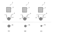
- FIG. 1 is a diagram for explaining a correction method of a correction processing unit of an apparatus 1 for measuring the size of cells in a culture solution of the present invention.
- FIG. 2 is a diagram for explaining a correction method of the correction processing unit of the apparatus 1 for measuring the size of cells in the culture medium of the present invention.
- FIG. 3 shows another embodiment of the device 1 of the present invention.
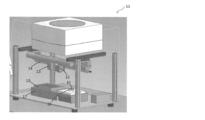
- FIG. 4 is a diagram illustrating an example of a cell transfer device.
- apparatus for measuring the size of cells in a culture solution (hereinafter, simply referred to as “apparatus”) and a cell transfer apparatus will be described in detail.
- the apparatus 1 of the present invention includes at least an imaging unit 2 and a correction processing unit (not shown).
- the size of the cell 4 in the incubator such as the well plate 3 is imaged by the imaging unit 2, as shown in FIG. 1A, when there is no culture solution in the well, the cell image captured by the imaging unit 2
- the size of 41 matches the size of the actual cell 4.
- the size of the cell image 41 imaged by the imaging unit 2 depends on the amount of the culture solution 5 and the generated meniscus. This is different from the actual size of the cell 4.
- the change in the size of the cell image 41 when the cells 4 whose sizes are known in advance are put into the wells and the culture solution 5 is changed in various amounts and imaged.
- the amount is stored in the form of a table or correction formula in association with the liquid amount.
- the amount 5 of the culture medium in the well containing the cells 4 is measured from the image captured by the imaging unit 2, and the size of the cell image 41 in the imaged culture medium 5 is measured based on the above table or the correction formula.
- the correct size of the cells 4 in the culture solution 5 can be measured by correcting the thickness according to the amount of the culture solution 5.
- the “liquid amount” does not mean the absolute amount of the culture solution 5 in the well, but is a table stored in the correction processing unit by analyzing the image captured by the imaging unit 2. Or it means a numerical value that can be included in the calculation formula. For example, the distance between the interface of the culture solution and the upper end of the well, the distance between the bottom of the well and the interface of the culture solution, and the like.
- FIG. 2 shows an example of a method for measuring the amount of the culture solution 5 in the well.
- the imaging unit 2 is imaged obliquely from above the well, and as shown by the dotted line in FIG. 2 (A), the interface of the culture medium and the upper end of the well are determined. The distance from the interface of the culture medium in the well to the upper end of the well is measured from the angle at which the imaging unit 2 is tilted.
- the imaging unit 2 is arranged on the side surface of the well, and as shown by the dotted line in FIG. 2 (B), from the captured image to the upper end of the well from the interface of the culture medium Measuring distance.
- FIGS. 2A and 2B are an example of a method for measuring the liquid amount, and may be other methods.
- the imaging unit 2 used in the measurement method shown in FIGS. 2A and 2B may be the same as or different from the imaging unit 2 for imaging the cell 4 from above the well.
- an imaging unit moving unit for moving the position of the imaging unit 2 to the position directly above the well and obliquely above or to the side surface may be provided.
- the image pickup unit moving means is not particularly limited as long as the position of the image pickup unit can be changed.
- the image pickup surface of the image pickup unit 2 is further added to a known three-dimensional moving mechanism of X, Y, and Z axes used in a microscope or the like. It is sufficient to provide a rotating means for changing the direction.
- the incubator for cells 4 can image the well from the side, such as a 6-well plate.
- the image may be captured by the method shown in FIG.
- the table or correction formula stored in the correction processing unit is preferably a table or correction formula measured under various conditions as much as possible.
- Factors that change the size of the cells 4 when imaged by the imaging unit 2 include, in addition to the amount of the culture solution 5, the type and concentration of the culture solution, and the change in meniscus shape caused by the type and concentration. Conceivable. Further, when the hydrophilicity (hydrophobicity) of the well inner surface is different, the shape of the meniscus of the culture solution may be changed. Therefore, when creating a table or correction formula, it is preferable to create various tables or correction formulas that combine not only the amount of the culture solution but also various factors such as the type, concentration, and type of well.
- the imaging unit 2 is not particularly limited as long as a visible image can be captured, and a commercially available camera such as a CMOS camera may be used.
- the type of cell 4 to be measured using the apparatus 1 of the present invention is not particularly limited, but it can be suitably used for measuring stem cells such as three-dimensionally cultured cells and ES cells / iPS cells.
- the culture solution 5 may be appropriately selected according to the cells 4 to be cultured.
- FIG. 3 is a view showing another embodiment of the apparatus 1 of the present invention, and shows an example in which a liquid amount adjusting mechanism 6 capable of injecting and / or discharging a culture solution is provided.
- a liquid amount adjusting mechanism 6 capable of injecting and / or discharging a culture solution.
- FIG. 3 (A) even if the liquid volume 5 of the culture liquid contained in each well is not uniform, the liquid culture medium 5 is injected and / or discharged using the liquid volume adjusting mechanism 6.
- the amount of the culture solution in each well can be made constant.
- the size of the cells 4 in the culture solution 5 can be reduced even if the amount of the culture solution 5 in each well of the well plate is different.
- the liquid volume adjusting mechanism 6 is provided, the liquid volume of the culture liquid 5 can be made constant, so that the types of tables or correction formulas stored in the correction processing section can be reduced.
- the liquid amount adjusting mechanism 6 is not particularly limited as long as the culture solution can be injected and / or discharged, and a syringe pump or the like may be used.
- the apparatus 1 of the present invention can accurately measure the size of the cells in the culture solution 5, it is incorporated into a cell transfer device for transferring the cells in the incubator to a cell chamber such as an artificial organ. Can be used. It can also be used to confirm the size of cells during culture.
- FIG. 4 shows an example of the cell delivery device.
- the cell transfer device 11 shown in FIG. 4 is a diagram for controlling the imaging unit 12, a syringe pump 13 that can be fitted with a syringe, a syringe pump drive unit 14 for driving the syringe pump 13, and a syringe pump drive unit 14.
- a control unit that is not included, and a storage unit (not shown) that stores the position of the cell and the transport destination of the cell.
- the storage unit of the cell transfer device 11 stores the positions of individual cells on the plate 15 in the storage unit by imaging the plate 15 in which the cells are cultured with the imaging unit 12, and also a cell chamber that is a cell transfer destination
- the individual positions of the recesses 61 formed in 16 are also stored in the storage unit.
- a control part controls the drive of the syringe pump drive part 14 based on the position of the cell memorize
- worn is located in the vicinity of a cell and the recessed part 61. It can move accurately.
- the imaging unit 12 is not particularly limited as long as a visible image can be captured, and a commercially available camera such as a CMOS camera may be used.
- the cell carrier 11 is provided with a mounting table 17 on which the plate 15 (incubator 3) is mounted, and an illumination unit (not shown) is provided inside the mounting table 17. Also good.
- the syringe pump 13 is not particularly limited as long as cells can be sampled with a syringe to be mounted, and a syringe pump known in the field of an automatic analyzer or the like may be used.
- the syringe for sampling the stem cells is different from the syringe for sampling the sample quantitatively, and is for taking out a substantially spherical stem cell mass having a diameter of 1 mm to 3 mm from the plate 15 and transporting it to the recess 61. is there. Therefore, the inner diameter of the syringe is preferably a substantially circular shape of 1 mm to 3 mm.
- the cell transport apparatus 11 shown in FIG. 4 can transport a cell etc. more correctly than the conventional automatic analyzer by providing a memory
- the syringe pump drive unit 14 for driving the syringe pump 13 can move the syringe pump 13 in the X-axis, Y-axis, and Z-axis directions. After moving to a predetermined position, the syringe pump 13 is driven to cell If it can take out from the plate 15 and can convey to the recessed part 61, there will be no restriction
- a driving source (not shown) and a driving force transmission mechanism that transmits the driving force of the driving source to the syringe pump 13 may be provided.
- a pulse motor or an ultrasonic motor may be used as the driving source.
- areas such as an automatic analyzer, for example, for a drive force transmission mechanism.
- the driving of the syringe pump 13 may be controlled so as to perform suction and discharge after reaching the place set by the syringe pump 13.
- the syringe pump 13 is provided with a telescopic syringe part
- the syringe pump drive part 14 is It is only necessary that the syringe pump 13 can be moved in the X-axis and Y-axis directions.
- you may provide as a separate body from the syringe pump 13 you may use the syringe pump 13 as the liquid quantity adjustment mechanism 6.
- the driving force from the driving force transmission mechanism may be directly transmitted to the syringe pump 13, but an attachment portion of the syringe pump 13 (not shown) may be provided to transmit the driving force so that the attachment portion moves. Moreover, you may attach the imaging part 12 to an attaching part. By attaching the imaging unit 12 to the attachment unit, it is not necessary to separately provide a mechanism for moving the imaging unit 12. Further, the driving force transmission mechanism may be provided with a driving force transmission mechanism in the horizontal direction of the X axis and the Y axis and a driving force transmission mechanism in the Z axis direction separately.
- X-axis, Y-axis, and Z-axis driving forces are transmitted to the syringe pump 13, and X-axis and Y-axis horizontal driving forces are transmitted to the imaging unit 12. Also good.
- the imaging unit 12 is provided with a zoom mechanism, the imaging unit 12 itself may not be moved in the Z-axis direction.
- the imaging unit 12 shown in FIG. 4 moves the imaging unit 12 in two directions of X and Y, or three directions of X, Y, and Z.
- the imaging section 2 may be provided separately from the imaging section 12 of the cell transport apparatus 11, or the cell transport apparatus 11.
- the imaging unit 12 may be shared. In that case, since the imaging unit 12 of the cell transport device 11 can only capture cells from above, a rotation unit may be provided to adjust the direction in which the imaging unit 12 can capture images.
- the amount of the culture solution 5 in the well is first measured using the device 1 of the present invention, and the cell image captured by the imaging unit 12 is measured.
- the correction processing unit it is possible to grasp the exact size of the cell that is actually transported. Therefore, when an artificial organ is produced using stem cells or the like, the total amount of substances such as hormones produced by the stem cells can be predicted more accurately.
- the size of cells in the incubator can be accurately measured by using the device for measuring the size of cells in the culture medium of the present invention and the cell transfer device, hormones produced by artificial organs, etc. Can be accurately predicted. Therefore, it is useful for surgery in the medical device industry and medical institutions that manufacture artificial organs.
Landscapes
- Chemical & Material Sciences (AREA)
- Life Sciences & Earth Sciences (AREA)
- Health & Medical Sciences (AREA)
- General Physics & Mathematics (AREA)
- Analytical Chemistry (AREA)
- Engineering & Computer Science (AREA)
- Physics & Mathematics (AREA)
- General Health & Medical Sciences (AREA)
- Biochemistry (AREA)
- Zoology (AREA)
- Organic Chemistry (AREA)
- Wood Science & Technology (AREA)
- Pathology (AREA)
- Immunology (AREA)
- Bioinformatics & Cheminformatics (AREA)
- Dispersion Chemistry (AREA)
- Biotechnology (AREA)
- Genetics & Genomics (AREA)
- Biomedical Technology (AREA)
- General Engineering & Computer Science (AREA)
- Cell Biology (AREA)
- Sustainable Development (AREA)
- Microbiology (AREA)
- Theoretical Computer Science (AREA)
- Apparatus Associated With Microorganisms And Enzymes (AREA)
Abstract
培養液中の細胞の大きさを測定する装を提供することを課題とする。 撮像部、及び該撮像部で撮像した培養液中の細胞の大きさを補正する補正処理部、を含む、培養液中の細胞の大きさを測定する装置により、培養液中の細胞の大きさを測定することができる。
Description
本発明は、培養液中の細胞の大きさを測定する装置及び細胞搬送装置に関し、特に、培養液中の細胞の大きさを補正する補正処理部を設けることで、ウェル中の細胞の大きさを正確に測定することができる装置及び該装置を含む細胞搬送装置に関する。
心臓、肺、肝臓、腎臓、膵臓などの臓器、骨、目等の生体を構成する組織の機能が損なわれると種々の病気になり、重い場合には生命の危機にさらされる。生体組織の病気が比較的軽症の場合は、投薬・手術等により病変部分を治癒することが可能である。しかしながら、生体組織の機能が著しく低下し治癒が困難な場合は、生体組織の機能を代行するために、人工臓器が用いられている。
人工臓器は、セラミック製の人工骨やインプラント、ペースメーカー等の機械要素からなる人工臓器、生きた細胞を用いた組織工学により作製した人工臓器が知られている。後者の人工臓器としては、例えば、3次元培養した膵島および/または膵島細胞塊を高分子膜によって膵内分泌細胞を被包し、患者の皮下あるいは腹膣内等に移植できるようにした拡散チャンバー型人工臓器が知られている(特許文献1参照)。また、シリコーンゴムリング2の両開口端面にポリカーボネイト製の免疫隔離膜を接着してなる容器Vの中に失われた本来の膵臓の代替となりうる膵細胞とその機能を維持する細胞培養床5を封入してなる人工臓器用チャンバーであって、容器Vの中に、膵細胞の担体としてスポンジ状キチンを充填した人工臓器用チャンバーも知られている(特許文献2参照)。
近年、ES細胞やiPS細胞等の幹細胞を用いた研究が盛んにおこなわれている。所期の器官に分化した後の幹細胞は、その大きさから生産するホルモン等の量を予測できることから、人工臓器への応用が期待されている。ところで、幹細胞や三次元培養細胞は、人工臓器とは別の培養器で培養し、人工臓器用のチャンバーに移しているが、その際に、各細胞の大きさを正確に測定できると、ホルモン等の生産量が予測できるので好ましい。
ウェル等の培養器中の細胞の大きさを測定する装置としては、ウェルの上方に設けた光学系をウェルに対して相対的に走査移動させることで、ウェルの内容物を撮像することが知られている。しかしながら、ウェルの上方から撮像を行う場合、ウェルに注入された流動体の表面状態により画像がひずむ場合がある。そのため、赤外光で撮像可能で一定ピッチのグリッドパターンが形成された透明ステージに、流動体が注入されたウェルを有するマイクロプレートMを載置し、その下方から、白色光源、赤外光源が発する白色光および赤外光を選択的に入射させ、赤外光で撮像されたグリッドパターンの像における歪みから画像の歪み量を見積もり、この歪みをキャンセルするための補正を、白色光で撮像された画像に対して適用する撮像装置が知られている(特許文献3参照)。
しかしながら、上記特許文献3に記載されている発明は、グリッドパターン、白色光源及び赤外光源が細胞の大きさを補正する為に必要である。そのため、装置が煩雑になるという問題があった。
本発明は上記問題を解決する為になされた発明で、鋭意研究を行ったところ、(1)撮像部で撮像した培養液中の細胞の大きさを補正する補正処理部を設けることで、(2)グリッドパターン、白色光源及び赤外光源等の特別な手段を必要とせず、従来から細胞を撮像するために使用している光学系を用いて細胞の大きさを正確に測定できること、を新たに見出し、本発明を完成した。
すなわち、本発明の目的は、培養液中の細胞の大きさを測定する装置及び該装置を含む細胞搬送装置を提供することである。
(1)撮像部、及び該撮像部で撮像した培養液中の細胞の大きさを補正する補正処理部、
を含む、培養液中の細胞の大きさを測定する装置。
(2)前記補正処理部は、撮像部で撮像した画像から算出した培養液の液量、及び予め測定した培養液の液量と細胞の大きさの変化量のテーブル又は補正式に基づき、撮像した培養液中の細胞の大きさを補正する、上記(1)に記載の装置。
(3)培養液の液量が、細胞を培養しているウェルの斜め上方、又はウェルの側面から撮像した画像から算出される、上記(2)に記載の装置。
(4)各ウェル中の培養液の量を一定にするため、培養液を注入及び/又は排出できる液量調節機構を含む、上記(1)~(3)の何れか一に記載の装置。
(5)上記(1)~(4)の何れか一に記載の装置を含む、細胞搬送装置。
を含む、培養液中の細胞の大きさを測定する装置。
(2)前記補正処理部は、撮像部で撮像した画像から算出した培養液の液量、及び予め測定した培養液の液量と細胞の大きさの変化量のテーブル又は補正式に基づき、撮像した培養液中の細胞の大きさを補正する、上記(1)に記載の装置。
(3)培養液の液量が、細胞を培養しているウェルの斜め上方、又はウェルの側面から撮像した画像から算出される、上記(2)に記載の装置。
(4)各ウェル中の培養液の量を一定にするため、培養液を注入及び/又は排出できる液量調節機構を含む、上記(1)~(3)の何れか一に記載の装置。
(5)上記(1)~(4)の何れか一に記載の装置を含む、細胞搬送装置。
本発明の培養液中の細胞の大きさを測定する装置は、特別な手段は不要である。そのため、簡単な手段で培養液中の細胞の大きさを正確に測定することができる。
以下に、培養液中の細胞の大きさを測定する装置(以下、単に「装置」と記載することがある。)、及び細胞搬送装置について詳しく説明する。
図1及び図2は、本発明の装置1の補正処理部の補正方法を説明するための図である。図1(A)~(C)に示すように、本発明の装置1は、撮像部2、及び図示しない補正処理部を少なくとも含んでいる。
ウェルプレート3等の培養器中の細胞4の大きさを撮像部2で撮像すると、図1(A)に示すように、ウェル中に培養液が無い場合は、撮像部2で撮像した細胞画像41の大きさは、実際の細胞4の大きさと一致する。しかしながら、図1(B)及び(C)に示すように、ウェル中に培養液5がある場合、培養液5の量及び発生するメニスカスにより、撮像部2で撮像した細胞画像41の大きさは、実際の細胞4の大きさと異なる。
そのため、本発明の補正処理部には、予め大きさの分かっている細胞4をウェル中に投入し、培養液5の液量を様々に変えて撮像した時の細胞画像41の大きさの変化量を液量と関連付けてテーブル又は補正式にして記憶してある。そして、撮像部2で撮像した画像から、細胞4が入っているウェルの培養液の液量5を測定し、上記のテーブル又は補正式に基づき、撮像した培養液5中の細胞画像41の大きさを培養液5の液量に応じて補正することで、培養液5中の細胞4の正確な大きさを測定することができる。なお、本発明において「液量」とは、ウェル中の培養液5の絶対量を意味するのではなく、撮像部2で撮像した画像を解析することで、補正処理部に記憶してあるテーブル又は計算式に算入できる数値を意味する。例えば、培養液の界面とウェルの上端部の距離、ウェルの底部と培養液の界面の距離等、が挙げられる。
図2は、ウェル中の培養液5の液量の測定方法の一例を示している。図2(A)に示す方法では、撮像部2をウェルの斜め上方から撮像し、図2(A)の点線で示すように、撮像した画像から培養液の界面とウェルの上端部を決定し、撮像部2を傾ける角度からウェル中の培養液の界面からウェルの上端部までの距離を測定している。また、図2(B)に示す方法では、撮像部2をウェルの側面に配置させ、図2(B)の点線で示すように、撮像した画像から培養液の界面からウェルの上端部までの距離を測定している。なお、図2(A)及び(B)に示す例は、液量の測定方法の一例であって、他の方法であってもよい。
図2(A)及び(B)に示す測定方法に用いる撮像部2は、細胞4をウェルの上方から撮像するための撮像部2と同じであっても異なっていてもよい。撮像部2を共通化する場合、撮像部2の位置をウェルの真上と、斜め上方又は側面に移動させるための撮像部移動手段を設ければよい。撮像部移動手段は、撮像部の位置を変えることができれば特に制限はなく、顕微鏡等に用いられている公知のX、Y、Z軸の3次元方向移動機構に、更に撮像部2の撮像面の方向を変えるための回転手段を設ければよい。なお、図2(B)に示す方法は、細胞4の培養器が6ウェルプレート等、ウェルを側面から撮像できる場合に用いることができる。96ウェルプレート等、側面から撮像できないウェルを含む場合は、図2(A)に示す方法で撮像すればよい。
補正処理部に記憶するテーブル又は補正式は、可能な限り多様な条件で測定したテーブル又は補正式であることが望ましい。撮像部2で撮像した際に細胞4の大きさが変わる要因としては、培養液5の量に加え、培養液の種類及び濃度等、更に、種類及び濃度に起因するメニスカスの形状の変化等が考えられる。また、ウェル内面の親水度(疎水度)が異なると培養液のメニスカスの形状が変わる可能性がある。したがって、テーブル又は補正式を作成する際には、培養液の量のみでなく、種類や濃度、ウェルの種類等の様々な要因を組み合わせた多様なテーブル又は補正式を作成することが好ましい。
撮像部2は、可視画像が撮像できれば特に制限はなく、CMOSカメラ等の市販のカメラを用いればよい。また、本発明の装置1を用いて測定する細胞4の種類は特に制限はないが、3次元培養した細胞、ES細胞・iPS細胞等の幹細胞の測定に好適に使用することができる。また、培養液5は、培養する細胞4に応じて、適宜選択すればよい。
図3は、本発明の装置1の他の実施形態を示す図で、培養液を注入及び/又は排出できる液量調節機構6を設けた例を示している。図3(A)に示すように各ウェルに含まれる培養液の液量5が不均一であっても、液量調整機構6を用いて培養液5を注入及び/又は排出することで、図3(B)に示すように各ウェル中の培養液の量を一定にすることができる。補正処理部に記憶するテーブル又は補正式の種類を可能な限り多くすることで、ウェルプレートの各ウェルの培養液5の液量が異なっていても、培養液5中の細胞4の大きさを正確に測定することができるが、液量調節機構6を設けると培養液5の液量を一定にできるので、補正処理部に記憶するテーブル又は補正式の種類を少なくすることができる。液量調節機構6は、培養液を注入及び/又は排出できれば特に制限はなく、シリンジポンプ等を用いればよい。
本発明の装置1は、培養液5中の細胞の大きさを正確に測定することができるので、培養器中の細胞を、人工臓器等のセルチャンバーに搬送するための細胞搬送装置等に組み込んで用いることができる。また、培養途中の細胞のサイズを確認するためにも使用することができる。
図4は、細胞搬送装置の一例を示している。図4に示す細胞搬送装置11は、撮像部12、シリンジを先端に装着できるシリンジポンプ13、シリンジポンプ13を駆動するためのシリンジポンプ駆動部14、シリンジポンプ駆動部14を制御するための図示していない制御部、細胞及び細胞の搬送先の位置を記憶する図示しない記憶部、を少なくとも含んでいる。
細胞搬送装置11の記憶部は、細胞を培養したプレート15を撮像部12で撮像することでプレート15上の個々の細胞の位置を記憶部に記憶し、また、細胞の搬送先であるセルチャンバー16に形成されている凹部61の個々の位置も記憶部に記憶している。そして、制御部は記憶部に記憶されている細胞と凹部61の位置に基づき、シリンジポンプ駆動部14の駆動を制御することから、シリンジポンプ13に装着するシリンジを、細胞及び凹部61の近傍に正確に移動することができる。
撮像部12は、可視画像が撮像できれば特に制限はなく、CMOSカメラ等の市販のカメラを用いればよい。なお、撮像した細胞の画像を解析し易くするために、細胞搬送装置11にプレート15(培養器3)を載置する載置台17を設け、載置台17の内部に図示しない照明部を設けてもよい。
シリンジポンプ13は、装着するシリンジで細胞をサンプリングできれば特に制限はなく、自動分析装置等の分野で公知のシリンジポンプを用いればよい。また、幹細胞をサンプリングするためのシリンジは、サンプルを定量サンプリングするためのシリンジと異なり、直径が1mm~3mmのほぼ球形の幹細胞の塊をプレート15から取り出して、凹部61に搬送するためのものである。そのため、シリンジの内径は1mm~3mmの略円形状とすることが好ましい。なお、図4に示す細胞搬送装置11は、記憶部を設けることで、従来の自動分析装置よりより正確に細胞等の搬送をすることができるが、従来の細胞搬送装置のように、記憶部を設けなくてもよい。
シリンジポンプ13を駆動するためのシリンジポンプ駆動部14は、シリンジポンプ13をX軸、Y軸、Z軸方向に移動することができ、所定の位置に移動した後にシリンジポンプ13を駆動して細胞をプレート15から取り出し、凹部61に搬送できれば特に制限は無い。X軸、Y軸、Z軸方向への移動機構は、例えば、図示しない駆動原及び該駆動原の駆動力をシリンジポンプ13に伝達する伝達する駆動力伝達機構を設ければよい。駆動原としては、例えば、パルスモーター、超音波モーター等を用いればよい。また、駆動力伝達機構は、例えば、自動分析装置等の分野で公知の3次元駆動機構を用いればよい。
また、シリンジポンプ13の駆動は、シリンジポンプ13が設定した場所に到達した後、吸引・排出等を行うように制御すればよい。なお、上記には、シリンジポンプ13をX軸、Y軸、Z軸方向に移動する例を示しているが、シリンジポンプ13が伸縮自在のシリンジ部を備える場合は、シリンジポンプ駆動部14は、シリンジポンプ13をX軸及びY軸方向に移動できればよい。なお、本発明の装置1に液量調整機構6を設ける場合、シリンジポンプ13とは別体として設けてもよいが、シリンジポンプ13を液量調整機構6として用いてもよい。
駆動力伝達機構からの駆動力は、直接シリンジポンプ13に伝達してもよいが、図示しないシリンジポンプ13の取付部を設け、取付部が移動するように駆動力を伝達してもよい。また、取付部には撮像部12を取り付けてもよい。撮像部12を取付部に取り付けることで、撮像部12を移動する為の機構を別途設ける必要はない。また、駆動力伝達機構は、X軸とY軸の水平方向への駆動力伝達機構とZ軸方向への駆動力伝達機構を別々に設けてもよい。シリンジポンプ13には、X軸、Y軸及びZ軸の3方向の駆動力が伝達するようにし、撮像部12にはX軸及びY軸の水平方向の駆動力が伝達するようにしておいても良い。撮像部12がズーム機構を設けている場合は、撮像部12自体をZ軸方向に移動しなくてもよい。
図4に示す撮像部12は、撮像部12をX、Yの2方向、又はX、Y、Zの3方向に移動するようになっている。本発明の培養液中の細胞の大きさを測定する装置1を細胞搬送装置11に組み込む場合、細胞搬送装置11の撮像部12とは別に撮像部2を設けてもよいし、細胞搬送装置11の撮像部12と共通化してもよい。その場合、細胞搬送装置11の撮像部12は、上方からしか細胞を撮像できないので、撮像部12が撮像できる方向を調整するための回転手段を設ければよい。
図4に示す細胞搬送装置11を用いて細胞を搬送する際に、本発明の装置1を用いて先ず先ずウェルの培養液5の液量を測定し、そして撮像部12で撮像した細胞画像を補正処理部で補正することで、実際に搬送する細胞の正確な大きさを把握できる。したがって、幹細胞等を用いて人工臓器を作製する場合、幹細胞が生産するホルモン等の物質の総量をより正確に予測することができる。
本発明の培養液中の細胞の大きさを測定する装置、及び細胞搬送装置を用いると、培養器中の細胞の大きさを正確に測定することができることから、人工臓器等が生産するホルモン等の量を正確に予測することができる。したがって、人工臓器を製造する医療機器産業や医療機関における手術に有用である
Claims (5)
- 撮像部、及び該撮像部で撮像した培養液中の細胞の大きさを補正する補正処理部、
を含む、培養液中の細胞の大きさを測定する装置。 - 前記補正処理部は、撮像部で撮像した画像から算出した培養液の液量、及び予め測定した培養液の液量と細胞の大きさの変化量のテーブル又は補正式に基づき、撮像した培養液中の細胞の大きさを補正する、請求項1に記載の装置。
- 培養液の液量が、細胞を培養しているウェルの斜め上方、又はウェルの側面から撮像した画像から算出される、請求項2に記載の装置。
- 各ウェル中の培養液の量を一定にするため、培養液を注入及び/又は排出できる液量調節機構を含む、請求項1~3の何れか一項に記載の装置。
- 請求項1~4の何れか一項に記載の装置を含む、細胞搬送装置。
Priority Applications (2)
| Application Number | Priority Date | Filing Date | Title |
|---|---|---|---|
| JP2018505165A JPWO2017158792A1 (ja) | 2016-03-17 | 2016-03-17 | 培養液中の細胞の大きさを測定する装置、及び細胞搬送装置 |
| PCT/JP2016/058515 WO2017158792A1 (ja) | 2016-03-17 | 2016-03-17 | 培養液中の細胞の大きさを測定する装置、及び細胞搬送装置 |
Applications Claiming Priority (1)
| Application Number | Priority Date | Filing Date | Title |
|---|---|---|---|
| PCT/JP2016/058515 WO2017158792A1 (ja) | 2016-03-17 | 2016-03-17 | 培養液中の細胞の大きさを測定する装置、及び細胞搬送装置 |
Publications (1)
| Publication Number | Publication Date |
|---|---|
| WO2017158792A1 true WO2017158792A1 (ja) | 2017-09-21 |
Family
ID=59851404
Family Applications (1)
| Application Number | Title | Priority Date | Filing Date |
|---|---|---|---|
| PCT/JP2016/058515 Ceased WO2017158792A1 (ja) | 2016-03-17 | 2016-03-17 | 培養液中の細胞の大きさを測定する装置、及び細胞搬送装置 |
Country Status (2)
| Country | Link |
|---|---|
| JP (1) | JPWO2017158792A1 (ja) |
| WO (1) | WO2017158792A1 (ja) |
Citations (4)
| Publication number | Priority date | Publication date | Assignee | Title |
|---|---|---|---|---|
| JP2004245824A (ja) * | 2003-02-14 | 2004-09-02 | Dr Chip Biotechnology Inc | 側壁付微細アレイバイオチップ反射型画像アクセス及び分析装置、並びにその方法 |
| JP2010223676A (ja) * | 2009-03-23 | 2010-10-07 | Nikon Corp | 観察装置 |
| JP2013148441A (ja) * | 2012-01-19 | 2013-08-01 | Dainippon Screen Mfg Co Ltd | 画像処理方法 |
| JP2013170861A (ja) * | 2012-02-20 | 2013-09-02 | Dainippon Screen Mfg Co Ltd | 撮像装置、試料保持プレートおよび撮像方法 |
Family Cites Families (1)
| Publication number | Priority date | Publication date | Assignee | Title |
|---|---|---|---|---|
| US9360414B2 (en) * | 2011-10-14 | 2016-06-07 | University of Pittsburgh—of the Commonwealth System of Higher Education | Light refraction imaging to measure liquid volume |
-
2016
- 2016-03-17 WO PCT/JP2016/058515 patent/WO2017158792A1/ja not_active Ceased
- 2016-03-17 JP JP2018505165A patent/JPWO2017158792A1/ja active Pending
Patent Citations (4)
| Publication number | Priority date | Publication date | Assignee | Title |
|---|---|---|---|---|
| JP2004245824A (ja) * | 2003-02-14 | 2004-09-02 | Dr Chip Biotechnology Inc | 側壁付微細アレイバイオチップ反射型画像アクセス及び分析装置、並びにその方法 |
| JP2010223676A (ja) * | 2009-03-23 | 2010-10-07 | Nikon Corp | 観察装置 |
| JP2013148441A (ja) * | 2012-01-19 | 2013-08-01 | Dainippon Screen Mfg Co Ltd | 画像処理方法 |
| JP2013170861A (ja) * | 2012-02-20 | 2013-09-02 | Dainippon Screen Mfg Co Ltd | 撮像装置、試料保持プレートおよび撮像方法 |
Non-Patent Citations (1)
| Title |
|---|
| WENG, J. ET AL.: "Camera Calibration with Distortion Models and Accuracy Evaluation", IEEE TRANSACTIONS ON PATTERN ANALYSIS AND MACHINE INTELLIGENCE, vol. 14, no. 10, October 1992 (1992-10-01), pages 965 - 980, XP000328810, DOI: doi:10.1109/34.159901 * |
Also Published As
| Publication number | Publication date |
|---|---|
| JPWO2017158792A1 (ja) | 2019-01-17 |
Similar Documents
| Publication | Publication Date | Title |
|---|---|---|
| Pröhl et al. | In vivo analysis of the biocompatibility and bone healing capacity of a novel bone grafting material combined with hyaluronic acid | |
| WO2013180423A1 (ko) | 카메라와 프로젝터가 스테이지 수평 회전축 회전유동부와 결합된 2축 모션부를 갖춘 치과용 데스크탑 3차원 스캐너 | |
| JP2016077226A (ja) | 培養観察装置および培養観察システム | |
| KR101785693B1 (ko) | 계수용 장치 | |
| Jazayeri et al. | Advancements in craniofacial prosthesis fabrication: A narrative review of holistic treatment | |
| Heintz et al. | Image-guided, laser-based fabrication of vascular-derived microfluidic networks | |
| KR101740334B1 (ko) | 치과용 3차원 스캐너 | |
| CN113242715A (zh) | 体内深层组织的显微图像采集系统及显微图像提供方法 | |
| Li et al. | Guided bone regeneration in a periodontally compromised individual with autogenous tooth bone graft: a radiomics analysis | |
| Shao et al. | Modular scaffolds with intelligent visual guidance system for in situ bone tissue repair | |
| JPWO2017158792A1 (ja) | 培養液中の細胞の大きさを測定する装置、及び細胞搬送装置 | |
| TWI813713B (zh) | 細胞觀察裝置 | |
| KR20190080747A (ko) | 타임 랩스 세포 촬영 장치 | |
| KR101798501B1 (ko) | 세포 배양장치 | |
| Gabor et al. | Ceramic scaffolds for bone augmentation: design and characterization with SEM and confocal microscopy | |
| EP3345535B1 (en) | Window apparatus for obtaining microscopic image of in vivo breast tissue and method for obtaining image using same | |
| WO2022094072A1 (en) | Cell imaging systems and methods | |
| JP6715321B2 (ja) | 細胞搬送装置、細胞搬送方法、及び人工臓器の製造方法 | |
| KR20230058421A (ko) | 3d 생체구조 인쇄 시스템 및 방법 | |
| CN208520781U (zh) | 药液灯检仪 | |
| JP2013027384A (ja) | 顕微鏡用細胞収容器 | |
| Benabdallah-M’Rabat et al. | Influence of camera position, implant angulation and implant reference on the accuracy of complete arch implant recordings with photogrammetry | |
| CN215799631U (zh) | 一种培养皿观察组件 | |
| Burger et al. | Process Development of a Generative Method for Partial and Controlled Integration of Active Substances into Open-Porous Matrix Structures | |
| US20260003172A1 (en) | Microscope observation system |
Legal Events
| Date | Code | Title | Description |
|---|---|---|---|
| WWE | Wipo information: entry into national phase |
Ref document number: 2018505165 Country of ref document: JP |
|
| NENP | Non-entry into the national phase |
Ref country code: DE |
|
| 121 | Ep: the epo has been informed by wipo that ep was designated in this application |
Ref document number: 16894410 Country of ref document: EP Kind code of ref document: A1 |
|
| 122 | Ep: pct application non-entry in european phase |
Ref document number: 16894410 Country of ref document: EP Kind code of ref document: A1 |