EP3345535B1 - Window apparatus for obtaining microscopic image of in vivo breast tissue and method for obtaining image using same - Google Patents
Window apparatus for obtaining microscopic image of in vivo breast tissue and method for obtaining image using same Download PDFInfo
- Publication number
- EP3345535B1 EP3345535B1 EP16842281.4A EP16842281A EP3345535B1 EP 3345535 B1 EP3345535 B1 EP 3345535B1 EP 16842281 A EP16842281 A EP 16842281A EP 3345535 B1 EP3345535 B1 EP 3345535B1
- Authority
- EP
- European Patent Office
- Prior art keywords
- chamber
- breast tissue
- window apparatus
- protrusion
- obtaining
- Prior art date
- Legal status (The legal status is an assumption and is not a legal conclusion. Google has not performed a legal analysis and makes no representation as to the accuracy of the status listed.)
- Active
Links
- 210000000481 breast Anatomy 0.000 title claims description 34
- 238000000034 method Methods 0.000 title claims description 14
- 238000001727 in vivo Methods 0.000 title claims description 9
- 239000006059 cover glass Substances 0.000 claims description 10
- 230000008569 process Effects 0.000 claims description 5
- 210000004027 cell Anatomy 0.000 description 13
- 230000001413 cellular effect Effects 0.000 description 7
- 241001465754 Metazoa Species 0.000 description 6
- 206010028980 Neoplasm Diseases 0.000 description 5
- 210000004204 blood vessel Anatomy 0.000 description 5
- 201000011510 cancer Diseases 0.000 description 5
- 206010006187 Breast cancer Diseases 0.000 description 2
- 208000026310 Breast neoplasm Diseases 0.000 description 2
- 230000015572 biosynthetic process Effects 0.000 description 2
- 230000009087 cell motility Effects 0.000 description 2
- 230000033001 locomotion Effects 0.000 description 2
- 230000004048 modification Effects 0.000 description 2
- 238000012986 modification Methods 0.000 description 2
- 230000003287 optical effect Effects 0.000 description 2
- 206010061218 Inflammation Diseases 0.000 description 1
- 102100024616 Platelet endothelial cell adhesion molecule Human genes 0.000 description 1
- 210000002821 alveolar epithelial cell Anatomy 0.000 description 1
- 238000010171 animal model Methods 0.000 description 1
- 230000008901 benefit Effects 0.000 description 1
- 230000007321 biological mechanism Effects 0.000 description 1
- 238000012258 culturing Methods 0.000 description 1
- 238000001514 detection method Methods 0.000 description 1
- 230000000694 effects Effects 0.000 description 1
- 210000002919 epithelial cell Anatomy 0.000 description 1
- 230000008020 evaporation Effects 0.000 description 1
- 238000001704 evaporation Methods 0.000 description 1
- 238000003384 imaging method Methods 0.000 description 1
- 239000007943 implant Substances 0.000 description 1
- 230000004054 inflammatory process Effects 0.000 description 1
- 230000003993 interaction Effects 0.000 description 1
- 230000007774 longterm Effects 0.000 description 1
- 230000004060 metabolic process Effects 0.000 description 1
- 230000007935 neutral effect Effects 0.000 description 1
- 230000003252 repetitive effect Effects 0.000 description 1
- 230000029058 respiratory gaseous exchange Effects 0.000 description 1
- 238000010186 staining Methods 0.000 description 1
- 239000000126 substance Substances 0.000 description 1
- 238000006467 substitution reaction Methods 0.000 description 1
- 230000002792 vascular Effects 0.000 description 1
Images


Classifications
-
- G—PHYSICS
- G02—OPTICS
- G02B—OPTICAL ELEMENTS, SYSTEMS OR APPARATUS
- G02B21/00—Microscopes
- G02B21/0004—Microscopes specially adapted for specific applications
- G02B21/002—Scanning microscopes
- G02B21/0024—Confocal scanning microscopes (CSOMs) or confocal "macroscopes"; Accessories which are not restricted to use with CSOMs, e.g. sample holders
- G02B21/0028—Confocal scanning microscopes (CSOMs) or confocal "macroscopes"; Accessories which are not restricted to use with CSOMs, e.g. sample holders specially adapted for specific applications, e.g. for endoscopes, ophthalmoscopes, attachments to conventional microscopes
-
- A—HUMAN NECESSITIES
- A61—MEDICAL OR VETERINARY SCIENCE; HYGIENE
- A61B—DIAGNOSIS; SURGERY; IDENTIFICATION
- A61B5/00—Measuring for diagnostic purposes; Identification of persons
-
- A—HUMAN NECESSITIES
- A61—MEDICAL OR VETERINARY SCIENCE; HYGIENE
- A61B—DIAGNOSIS; SURGERY; IDENTIFICATION
- A61B90/00—Instruments, implements or accessories specially adapted for surgery or diagnosis and not covered by any of the groups A61B1/00 - A61B50/00, e.g. for luxation treatment or for protecting wound edges
- A61B90/20—Surgical microscopes characterised by non-optical aspects
- A61B90/25—Supports therefor
-
- G—PHYSICS
- G02—OPTICS
- G02B—OPTICAL ELEMENTS, SYSTEMS OR APPARATUS
- G02B21/00—Microscopes
- G02B21/0004—Microscopes specially adapted for specific applications
- G02B21/002—Scanning microscopes
- G02B21/0024—Confocal scanning microscopes (CSOMs) or confocal "macroscopes"; Accessories which are not restricted to use with CSOMs, e.g. sample holders
- G02B21/0032—Optical details of illumination, e.g. light-sources, pinholes, beam splitters, slits, fibers
-
- G—PHYSICS
- G02—OPTICS
- G02B—OPTICAL ELEMENTS, SYSTEMS OR APPARATUS
- G02B21/00—Microscopes
- G02B21/34—Microscope slides, e.g. mounting specimens on microscope slides
-
- A—HUMAN NECESSITIES
- A61—MEDICAL OR VETERINARY SCIENCE; HYGIENE
- A61B—DIAGNOSIS; SURGERY; IDENTIFICATION
- A61B2503/00—Evaluating a particular growth phase or type of persons or animals
- A61B2503/40—Animals
-
- A—HUMAN NECESSITIES
- A61—MEDICAL OR VETERINARY SCIENCE; HYGIENE
- A61B—DIAGNOSIS; SURGERY; IDENTIFICATION
- A61B2562/00—Details of sensors; Constructional details of sensor housings or probes; Accessories for sensors
- A61B2562/02—Details of sensors specially adapted for in-vivo measurements
- A61B2562/0233—Special features of optical sensors or probes classified in A61B5/00
-
- A—HUMAN NECESSITIES
- A61—MEDICAL OR VETERINARY SCIENCE; HYGIENE
- A61B—DIAGNOSIS; SURGERY; IDENTIFICATION
- A61B5/00—Measuring for diagnostic purposes; Identification of persons
- A61B5/0059—Measuring for diagnostic purposes; Identification of persons using light, e.g. diagnosis by transillumination, diascopy, fluorescence
- A61B5/0082—Measuring for diagnostic purposes; Identification of persons using light, e.g. diagnosis by transillumination, diascopy, fluorescence adapted for particular medical purposes
- A61B5/0091—Measuring for diagnostic purposes; Identification of persons using light, e.g. diagnosis by transillumination, diascopy, fluorescence adapted for particular medical purposes for mammography
-
- G—PHYSICS
- G02—OPTICS
- G02B—OPTICAL ELEMENTS, SYSTEMS OR APPARATUS
- G02B21/00—Microscopes
- G02B21/0004—Microscopes specially adapted for specific applications
- G02B21/002—Scanning microscopes
- G02B21/0024—Confocal scanning microscopes (CSOMs) or confocal "macroscopes"; Accessories which are not restricted to use with CSOMs, e.g. sample holders
- G02B21/0052—Optical details of the image generation
- G02B21/0076—Optical details of the image generation arrangements using fluorescence or luminescence
-
- G—PHYSICS
- G02—OPTICS
- G02B—OPTICAL ELEMENTS, SYSTEMS OR APPARATUS
- G02B21/00—Microscopes
- G02B21/24—Base structure
- G02B21/26—Stages; Adjusting means therefor
Definitions
- the present disclosure relates to a window apparatus for obtaining a microscopic image of an in vivo breast tissue and a method for obtaining image using the same.
- a confocal laser scanning microscope using fluorescent signals is used to observe cellular-level and molecular-level phenomenon.
- Evaporation of moisture and inflammation may be generated on the breast tissues existing under the skin, unlike other tissues, due to cutting of the skin for taking images of the breast tissues, so there is a limit in a repetitive and long-term imaging technology.
- lactiferous ducts which are a characteristic of breast tissues, and vascular tissues around the lactiferous ducts.
- the present disclosure provides a window apparatus for obtaining microscopic image in vivo of a breast tissue
- the apparatus can obtain real-time cellular-level and molecular-level microscopic images of a lactiferous duct and a blood vessel of a breast tissue stably and for a long period of time without extracting the breast tissue while maintaining an in vivo environment, and a method of obtaining an image using the apparatus.
- a plurality of holes that communicate with each other may be formed along the outer circumference surface of the first chamber and the outer side of the second chamber.
- the first chamber and the second chamber may be combined with each other by one or more bolts or threads.
- a first protrusion and a second protrusion that are stepped on sides facing each other are formed on a side of the chamber holder, and the first chamber and the second chamber may be fixed between the first protrusion and the second protrusion.
- a first chamber seat where the first chamber is placed may be formed on the first protrusion and the second protrusion.
- the first chamber may be larger in outer diameter than the second chamber, the outer diameter of the first chamber may correspond to the length of first facing sides at the upper portion of the first chamber seat, and the first chamber may be tightly fitted on the first facing sides.
- the outer diameter of the second chamber may correspond to the length between second facing sides at the lower part of the first chamber seat.
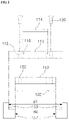
- FIG. 1 is a perspective view showing a window apparatus according to an embodiment
- FIG. 2 is a vertical cross-sectional view of the window apparatus according to an embodiment
- FIG. 3 is a view showing the use state of the window apparatus according to an embodiment.
- a window apparatus may include a first chamber 100, a second chamber 102, and a chamber holder 104.
- the first chamber 100 and second chamber 102 have a ring-shaped structure with an open window at the center.
- the first chamber 100 is disposed close to an objective lens 140 of a confocal microscope system and has a cover glass seat 116 where a cover glass 114 is placed.
- a plurality of holes 112 and 122 that can communicate with each other are formed respectively outside the first chamber 100 and the second chamber 102.
- the skin of a breast of the animal is cut and a cut breast tissue is placed between the first chamber 100 and the second chamber 102.
- the tissue placed between the first chamber 100 and the second chamber 102 is observed through the open window 110 of the first chamber 100 and the second chamber 102.
- the first chamber 100 and the second chamber 102 are combined by a plurality of bolts 130, nuts 132, and threads (not shown).
- a chamber holder 104 is provided to fix the first chamber 100 and the second chamber 102 and keep the cover glass 114 placed on the first chamber 100 and the objective lens 140 in parallel.
- the chamber holder 104 may have a tilting mount seat 152 where a tilting mount is placed and two protrusions of a first protrusion 154-1 and a second protrusion 154-2 that extending from a side of the tilting mount seat 152.
- the tilting mount seat 152 has a plurality of fastening holes 156 and the tilting mount is coupled to at least some of the fastening holes 156.
- the first protrusion 154-1 and the second protrusion 154-2 extend in parallel with each other and each have a stepped portion.
- a first chamber seat 158 is formed on the sides facing each other of the first protrusion 154-1 and the second protrusion 154-2.
- the first chamber 100 is larger in outer diameter than the second chamber 102.
- the outer diameter of the first chamber 100 corresponds to the length d1 between first facing sides 155 of the first protrusion 154-1 and the second protrusion 154-2.
- the outer diameter of the second chamber 102 corresponds to the length d2 between second facing sides 157 of the first protrusion 154-1 and the second protrusion 154-2.
- first chamber 100 and the second chamber 102 are tightly fitted on the first facing sides 155 and the second facing sides 157.
- the first chamber 100 and the second chamber 102 fitted to each other, as described above, are fixed to the chamber holder 104 and then the angle of the window apparatus is adjusted through the tilting mount placed on the tilting mount seat 152.
- the tilting mount (not shown) according to the embodiment may be a kinematic tilting mount.
- FIG. 4 is a view showing the configuration of a confocal microscope system according to an embodiment.
- a process of obtaining an image according to the embodiment is as follows.
- the confocal microscope system includes four laser sources 400-1 to 400-4 respectively four wavelengths of 405nm, 488nm, 561nm, and 640nm within the visible light band, a polygonal rotation mirror 402, and a galvanometer mirror 404, and generates s XY raster scanning pattern, using these components.
- the confocal microscope system may include a plurality of neutral density filters ND, mirrors M, and Dichroic beam splitters DBS, and beam pass filters BPF and photomultiplier tubes(PMT) for detecting a fluorescent signal excited in a breast tissue.
- Images of a breast tissue were obtained from an actual animal model, using the confocal optical microscope using the window apparatus of the present disclosure.
- An optical system was designed to have an observation view of 250 ⁇ 250 ⁇ m 2 at the focus when using a ⁇ 40 objective lens (LUCPlanFL, NA0.6; Olympus), and a fluorescent signal was detected and processed by photomultiplier tubes and frame grabbers (Matrox, SOLIOS) that are provided for respective wavelengths such that 2D images having cellular-level resolution and being able to be sectioned in the Z-axial direction could be obtained at a speed of 30 sheets per second.
- LOCPlanFL ⁇ 40 objective lens
- SOLIOS frame grabbers
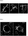
- FIG. 5 is a view showing the cells and structure of an imaged lactiferous duct of an Actin-GFP mouse, using the window apparatus and the confocal microscope system according to an embodiment.
- FIG. 6 is a view obtained by observing a lactiferous duct formation process at a cellular-level, using the window apparatus and the confocal microscope system according to an embodiment.
- FIG. 7 shows pictures obtained by observing movement of a cell at intervals of 30 minutes after implant and culture a breast cancer cell, MDA-MB-231-GFP Cell in a breast tissue.
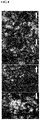
- FIG. 8 shows pictures obtained by observing blood vessels formed around a cancer cell, using the window apparatus and the confocal microscope system according to an embodiment.
Description
- The present disclosure relates to a window apparatus for obtaining a microscopic image of an in vivo breast tissue and a method for obtaining image using the same.
- A confocal laser scanning microscope using fluorescent signals is used to observe cellular-level and molecular-level phenomenon.
- Evaporation of moisture and inflammation may be generated on the breast tissues existing under the skin, unlike other tissues, due to cutting of the skin for taking images of the breast tissues, so there is a limit in a repetitive and long-term imaging technology.
- Due to this limit, most molecular biological studies are performed in the process of extracting, fixing, and then observing tissues.
- According to this method, it is difficult to observe changes in movement or shape of cells in living animal and it is difficult to conduct a study by observing lactiferous ducts, which are a characteristic of breast tissues, and vascular tissues around the lactiferous ducts.
- It is an important subject in a microscopic image study of breast tissues in vivo to find out for a long period of time cellular-level and molecular-level structures and interactions while maintaining the physiological environment of living animals.
- Accordingly, there is a need for an apparatus that can repeatedly obtain images of the same cell and tissue for a long time while observing a molecular biological mechanism that occurs in a lactiferous duct and a blood vessel in a breast tissue of a living creature.
US2005/196857A1 andUS4974952A disclose live cell chambers for obtaining microscopic images. - In order to solve the problems in the related art described above, the present disclosure provides a window apparatus for obtaining microscopic image in vivo of a breast tissue, the apparatus can obtain real-time cellular-level and molecular-level microscopic images of a lactiferous duct and a blood vessel of a breast tissue stably and for a long period of time without extracting the breast tissue while maintaining an in vivo environment, and a method of obtaining an image using the apparatus.
- According to an embodiment, there is provided a window apparatus for obtaining an in vivo microscopic image of a breast tissue according to claim 1.
- A plurality of holes that communicate with each other may be formed along the outer circumference surface of the first chamber and the outer side of the second chamber.
- The first chamber and the second chamber may be combined with each other by one or more bolts or threads.
- A first protrusion and a second protrusion that are stepped on sides facing each other are formed on a side of the chamber holder, and the first chamber and the second chamber may be fixed between the first protrusion and the second protrusion.
- A first chamber seat where the first chamber is placed may be formed on the first protrusion and the second protrusion.
- The first chamber may be larger in outer diameter than the second chamber, the outer diameter of the first chamber may correspond to the length of first facing sides at the upper portion of the first chamber seat, and the first chamber may be tightly fitted on the first facing sides.
- The outer diameter of the second chamber may correspond to the length between second facing sides at the lower part of the first chamber seat.
- According to another aspect, there is provided a method for obtaining an image using a confocal microscope system according to
claim 7. - The term 'comprising' used herein have the same meaning as terms 'including' or 'characterized by', not excluding additional non-stated elements, components, or steps in an apparatus or a method. The term 'consisting of' excludes additional elements, steps, or components not specifically stated. The term 'essentially consisting of' means comprising elements, components, or steps that do not actually influence basic characteristics in addition to stated elements, components, or steps in an apparatus or a method.
- According to embodiments of the present invention which use two chambers configured to have an open window and place a breast tissue therebetween, and a chamber holder configured to fix the two chambers and have a tilting mount seat where a tilting mount is placed, there is an advantage of stably obtaining images since it is possible to maintain the open window and an objective lens of the microscope in parallel while a living animal is placed on an objective area of a microscope.
-
-
FIG. 1 is a perspective view showing a window apparatus according to an embodiment; -
FIG. 2 is a vertical cross-sectional view of the window apparatus according to an embodiment; -
FIG. 3 is a view showing the use state of the window apparatus according to an embodiment; -
FIG. 4 is a view showing the configuration of a confocal microscope system according to an embodiment; -
FIG. 5 shows pictures of the cells and structure of an imaged lactiferous duct of an Actin-GFP mouse, using the window apparatus and the confocal microscope system according to an embodiment; -
FIG. 6 shows pictures obtained by observing a lactiferous duct formation process at a cellular-level, using the window apparatus and the confocal microscope system according to an embodiment; -
FIG. 7 shows pictures obtained by observing movement of a cell in terms of 30 minutes after implanting and culturing a breast cancer cell, MDA-MB-231-GFP Cell in a breast tissue; and -
FIG. 8 shows pictures obtained by observing blood vessels formed around a cancer cell, using the window apparatus and the confocal microscope according to an embodiment. - The present disclosure may be modified in various ways and implemented by various exemplary embodiments, so that specific exemplary embodiments are shown in the drawings and will be described in detail.
- However, it is to be understood that the present disclosure is not limited to the specific exemplary embodiments, but includes all modifications, equivalents, and substitutions included in the spirit and the scope of the present disclosure. Reference numerals are assigned to reference components in the following description of drawings.
- Hereinafter, exemplary embodiments will be described in detail with reference to the accompanying drawings.
-
FIG. 1 is a perspective view showing a window apparatus according to an embodiment,FIG. 2 is a vertical cross-sectional view of the window apparatus according to an embodiment, andFIG. 3 is a view showing the use state of the window apparatus according to an embodiment. - As shown in
FIGS. 1 to 3 , a window apparatus according to an embodiment may include afirst chamber 100, asecond chamber 102, and achamber holder 104. - The
first chamber 100 andsecond chamber 102 have a ring-shaped structure with an open window at the center. - The
first chamber 100 is disposed close to anobjective lens 140 of a confocal microscope system and has acover glass seat 116 where acover glass 114 is placed. - A plurality of
holes first chamber 100 and thesecond chamber 102. - According to a preferred embodiment, in order to observe a breast tissue of an animal, as shown in
FIG. 3 , the skin of a breast of the animal is cut and a cut breast tissue is placed between thefirst chamber 100 and thesecond chamber 102. - The tissue placed between the
first chamber 100 and thesecond chamber 102 is observed through theopen window 110 of thefirst chamber 100 and thesecond chamber 102. - The
first chamber 100 and thesecond chamber 102 are combined by a plurality ofbolts 130,nuts 132, and threads (not shown). - According to the embodiment, a
chamber holder 104 is provided to fix thefirst chamber 100 and thesecond chamber 102 and keep thecover glass 114 placed on thefirst chamber 100 and theobjective lens 140 in parallel. - The
chamber holder 104 may have atilting mount seat 152 where a tilting mount is placed and two protrusions of a first protrusion 154-1 and a second protrusion 154-2 that extending from a side of thetilting mount seat 152. - The
tilting mount seat 152 has a plurality of fastening holes 156 and the tilting mount is coupled to at least some of the fastening holes 156. - The first protrusion 154-1 and the second protrusion 154-2 extend in parallel with each other and each have a stepped portion.
- Preferably, a
first chamber seat 158 is formed on the sides facing each other of the first protrusion 154-1 and the second protrusion 154-2. - According to the embodiment, the
first chamber 100 is larger in outer diameter than thesecond chamber 102. - The outer diameter of the
first chamber 100 corresponds to the length d1 between first facing sides 155 of the first protrusion 154-1 and the second protrusion 154-2. - The outer diameter of the
second chamber 102 corresponds to the length d2 between second facingsides 157 of the first protrusion 154-1 and the second protrusion 154-2. - Accordingly, the
first chamber 100 and thesecond chamber 102 are tightly fitted on the first facing sides 155 and the second facingsides 157. - The
first chamber 100 and thesecond chamber 102 fitted to each other, as described above, are fixed to thechamber holder 104 and then the angle of the window apparatus is adjusted through the tilting mount placed on thetilting mount seat 152. - The tilting mount (not shown) according to the embodiment may be a kinematic tilting mount.
- When the
cover glass 114 disposed on thefirst chamber 100 and theobjective lens 140 are fixed in parallel with each other by adjusting the angle of the window apparatus through the kinematic tilting mount, it is possible to stably obtain images of a same part for a long period of time. -
FIG. 4 is a view showing the configuration of a confocal microscope system according to an embodiment. - A process of obtaining an image according to the embodiment is as follows.
- (1) Adjustment of angle of window apparatus
The angle of the window apparatus is adjusted using the tilting mount placed on thetilting mount seat 152 of the window apparatus. - (2) Emission of laser beam
As inFIG. 4 , laser beams having a plurality of wavelengths are radiated to a breast tissue through theopen window 110 of the window apparatus. - (3) Detection of fluorescent signal
A fluorescent signal excited in the cancer tissue is detected through a detector. - Referring to
FIG. 4 , the confocal microscope system according to the embodiment includes four laser sources 400-1 to 400-4 respectively four wavelengths of 405nm, 488nm, 561nm, and 640nm within the visible light band, apolygonal rotation mirror 402, and agalvanometer mirror 404, and generates s XY raster scanning pattern, using these components. - The confocal microscope system may include a plurality of neutral density filters ND, mirrors M, and Dichroic beam splitters DBS, and beam pass filters BPF and photomultiplier tubes(PMT) for detecting a fluorescent signal excited in a breast tissue.
- Images of a breast tissue were obtained from an actual animal model, using the confocal optical microscope using the window apparatus of the present disclosure.
- An optical system was designed to have an observation view of 250×250 µm2 at the focus when using a ×40 objective lens (LUCPlanFL, NA0.6; Olympus), and a fluorescent signal was detected and processed by photomultiplier tubes and frame grabbers (Matrox, SOLIOS) that are provided for respective wavelengths such that 2D images having cellular-level resolution and being able to be sectioned in the Z-axial direction could be obtained at a speed of 30 sheets per second.
-
FIG. 5 is a view showing the cells and structure of an imaged lactiferous duct of an Actin-GFP mouse, using the window apparatus and the confocal microscope system according to an embodiment. - As shown in
FIG. 5 , it was found that it was possible to observe an alveolar epithelial cell and a ductal epithelial cell that are lactiferous structures. -
FIG. 6 is a view obtained by observing a lactiferous duct formation process at a cellular-level, using the window apparatus and the confocal microscope system according to an embodiment. -
FIG. 7 shows pictures obtained by observing movement of a cell at intervals of 30 minutes after implant and culture a breast cancer cell, MDA-MB-231-GFP Cell in a breast tissue. - As shown in
FIGS. 6 and7 , it was possible to observe changes in shape of a cancer cell at a cellular-level by maintaining movement due to respiration and circulation of an animal, using the window apparatus according to the embodiment, with the window apparatus and the objective lens maintained in parallel. -
FIG. 8 shows pictures obtained by observing blood vessels formed around a cancer cell, using the window apparatus and the confocal microscope system according to an embodiment. - Referring to
FIG. 8 , it was possible to find dense blood vessels that a cancer cell has formed around it for metabolism by staining an antibody CD31 with a fluorescent substance. - Hereinabove, although the present disclosure is described by specific matters such as concrete components, and the like, embodiments, and drawings, they are provided only for assisting in the entire understanding of the present disclosure. Therefore, the present disclosure is not limited to the embodiments. Various modifications and changes may be made by those skilled in the art to which the present disclosure pertains from this description.
Claims (7)
- A window apparatus for obtaining an in vivo microscopic image of a breast tissue, the window apparatus comprising:a first chamber (100) configured to have a ring-shaped structure with an open window (110) at the center of the first chamber (100) for observing the breast tissue, wherein a cover glass (114) is placed on a cover glass seat (116) configured on the upper surface of the first chamber (100) and the lower part of the first chamber (100) is configured to hold a breast tissue for obtaining its in vivo microscopic image;a second chamber (102) configured to have an open window (110) at the center of the second chamber for observing the breast tissue, wherein the first chamber (100) and the second chamber (102) are configured to combine with each other, thereby holding the breast tissue therebetween for obtaining the in vivo microscopic image of the breast tissue; anda chamber holder (104) configured to fix the first chamber (100) and the second chamber (102) and have a tilting mount seat (152) where a tilting mount is placed to maintain the cover glass (114) and an objective lens (140) of a confocal microscope system in parallel with each other, andwherein the chamber holder (104) is configured to have, a first protrusion (154-1) and a second protrusion (154-2) extending from a side of the tilting mount seat (152), and wherein the sides of said two protrusions (154-1, 154-2) facing each other are stepped, and the first chamber (100) and the second chamber (102) are fixed between the first protrusion (154-1) and the second protrusion (154-2).
- The window apparatus of claim 1, wherein a plurality of holes (112, 122) that communicate with each other are formed along the outer circumference surface of the first chamber (100) and the second chamber (102).
- The window apparatus of claim 2, wherein the first chamber (100) and the second chamber (102) are combined with each other by one or more bolts (130) or threads.
- The window apparatus of claim 1, wherein a first chamber seat (158) where the first chamber (100) is placed is formed on the first protrusion (154-1) and the second protrusion (154-2).
- The window apparatus of claim 4, wherein the outer diameter of the first chamber (100) is larger than that of the second chamber (102), the outer diameter of the first chamber corresponds to a length between first facing sides (155) at the upper part of the first chamber seat (158), and thereby the first chamber (100) is tightly fitted between the first facing sides (155).
- The window apparatus of claim 4, wherein the outer diameter of the second chamber (102) corresponds to a length between second facing sides (157) at the lower part of the first chamber seat (158).
- A method for obtaining an image of a breast tissue using a confocal microscope system and a window apparatus wherein the window apparatus comprises a first chamber (100), a second chamber (102), and a chamber holder (104) which is configured to fix the first chamber (100) and the second chamber (102) combined with each other and have a tilting mount seat (152), the method comprising:adjusting the angle of the window apparatus by using a tilting mount placed on the tilting mount seat (152) of the window apparatus;radiating laser beams having a plurality of wavelengths to a breast tissue through an open window (110) of the first chamber (100) and the second chamber (102), wherein a cover glass (114) is placed on a cover glass seat (116) configured on the upper surface of the first chamber (100), and the first chamber (100) and the second chamber (102) of the window apparatus are configured to hold the breast tissue therebetween; anddetecting a fluorescent signal excited in the breast tissue,wherein the cover glass (114) and an objective lens (140) of the confocal microscope system are maintained in parallel with each other during a process of obtaining the image by adjusting the angle of the window apparatus using the tilting mount,wherein the first chamber (100) is configured to have a ring-shaped structure with an open window (110) at the center of the first chamber (100) for observing the breast tissue, wherein the lower part of the first chamber (100) is configured to hold a breast tissue for obtaining its image,wherein the second chamber (102) is configured to have an open window (110) at the center of the second chamber (102) for observing the breast tissue, wherein the first chamber (100) and the second chamber (102) are configured to combine with each other, thereby supporting the breast tissue,wherein the chamber holder (104) is configured to have, a first protrusion (154-1) and a second protrusion (154-2) extending from a side of the tilting mount seat (152), and wherein the sides of said two protrusions (154-1, 154-2) facing each other are stepped, and the first chamber (100) and the second chamber (102) are fixed between the first protrusion (154-1) and the second protrusion (154-2).
Applications Claiming Priority (2)
| Application Number | Priority Date | Filing Date | Title |
|---|---|---|---|
| KR1020150123212A KR101689879B1 (en) | 2015-08-31 | 2015-08-31 | Window apparatus for in vivo microscopic imaging of mammary tissue and method for obtaining image using the same |
| PCT/KR2016/009719 WO2017039315A1 (en) | 2015-08-31 | 2016-08-03 | Window apparatus for obtaining microscopic image of in vivo breast tissue and method for obtaining image using same |
Publications (3)
| Publication Number | Publication Date |
|---|---|
| EP3345535A1 EP3345535A1 (en) | 2018-07-11 |
| EP3345535A4 EP3345535A4 (en) | 2019-04-24 |
| EP3345535B1 true EP3345535B1 (en) | 2022-10-05 |
Family
ID=57733653
Family Applications (1)
| Application Number | Title | Priority Date | Filing Date |
|---|---|---|---|
| EP16842281.4A Active EP3345535B1 (en) | 2015-08-31 | 2016-08-31 | Window apparatus for obtaining microscopic image of in vivo breast tissue and method for obtaining image using same |
Country Status (6)
| Country | Link |
|---|---|
| US (1) | US11029504B2 (en) |
| EP (1) | EP3345535B1 (en) |
| JP (1) | JP6670385B2 (en) |
| KR (1) | KR101689879B1 (en) |
| CN (1) | CN108366727B (en) |
| WO (1) | WO2017039315A1 (en) |
Families Citing this family (3)
| Publication number | Priority date | Publication date | Assignee | Title |
|---|---|---|---|---|
| KR101849706B1 (en) | 2017-08-24 | 2018-04-18 | 한국화학연구원 | Apparutus for observing a biotissue, method of preparing thereof, and method for observing the biotissue using the same |
| WO2020080721A1 (en) * | 2018-10-17 | 2020-04-23 | 한국과학기술원 | Microscopic image acquisition system of in-vivo deep tissue and microscopic image providing method therefor |
| KR102186327B1 (en) * | 2018-10-17 | 2020-12-03 | 한국과학기술원 | System for in vivo microscopic imaging of deep tissue, and microscopic imaging method |
Family Cites Families (26)
| Publication number | Priority date | Publication date | Assignee | Title |
|---|---|---|---|---|
| JPS5612598Y2 (en) * | 1975-07-15 | 1981-03-24 | ||
| JPS5421752A (en) * | 1977-07-19 | 1979-02-19 | Toshiba Corp | Stage device for microscopes |
| US4974952A (en) * | 1988-03-31 | 1990-12-04 | Focht Daniel C | Live cell chamber for microscopes |
| JPH0618949U (en) * | 1992-08-12 | 1994-03-11 | 東ソー株式会社 | Continuous sampling device for collected samples |
| JP3214805B2 (en) * | 1995-07-17 | 2001-10-02 | シャープ株式会社 | Objective lens adjustment mechanism |
| JPH10165403A (en) * | 1996-12-13 | 1998-06-23 | Toshiba Corp | Biopsy instrument for mammography |
| US6411434B1 (en) * | 1999-02-17 | 2002-06-25 | Lucid, Inc. | Cassette for facilitating optical sectioning of a retained tissue specimen |
| EP1524542B1 (en) * | 2003-10-17 | 2008-07-02 | Olympus Corporation | Objective lens insertion tool & objective optical system attachment device |
| JP4579563B2 (en) * | 2004-03-15 | 2010-11-10 | オリンパス株式会社 | Objective optical system fixing device |
| KR100537070B1 (en) * | 2004-03-06 | 2005-12-16 | 이용진 | A Chamber-type Specimen Mount for a Microscope |
| JP4896874B2 (en) * | 2004-05-11 | 2012-03-14 | コーニンクレッカ フィリップス エレクトロニクス エヌ ヴィ | Measuring head for non-invasive blood analysis |
| JP4624725B2 (en) * | 2004-05-28 | 2011-02-02 | オリンパス株式会社 | Microscope observation system and microscope observation method |
| US20050280892A1 (en) * | 2004-05-28 | 2005-12-22 | Nobuyuki Nagasawa | Examination method and examination apparatus |
| WO2006124672A2 (en) * | 2005-05-12 | 2006-11-23 | University Of Alabama In Huntsville | Apparatus and method for incubating cell cultures |
| JP4885545B2 (en) * | 2006-01-12 | 2012-02-29 | オリンパス株式会社 | Observation device |
| JP4996977B2 (en) * | 2007-05-25 | 2012-08-08 | オリンパス株式会社 | Stabilizer and biological observation apparatus |
| US20090185980A1 (en) * | 2008-01-23 | 2009-07-23 | National Taiwan University | In vivo drug screening system |
| CA2731956A1 (en) * | 2008-07-25 | 2010-01-28 | Daniel S. Gareau | Rapid confocal microscopy to support surgical procedures |
| KR101042505B1 (en) * | 2008-11-27 | 2011-06-16 | 현대제철 주식회사 | A holder apparatus for specimen in scanning elctron microscope |
| US8259170B2 (en) * | 2009-08-24 | 2012-09-04 | Cellomics, Inc. | Integrated calibration sample bay for fluorescence readers |
| JP5700950B2 (en) * | 2010-04-21 | 2015-04-15 | キヤノン株式会社 | Biological information acquisition device |
| JP5779963B2 (en) * | 2011-04-28 | 2015-09-16 | ナノフォトン株式会社 | Observation sample sealed container |
| JP2013090867A (en) * | 2011-10-27 | 2013-05-16 | Canon Inc | Object information acquiring apparatus and method for controlling the same |
| JP5930364B2 (en) * | 2011-11-28 | 2016-06-08 | 国立大学法人京都大学 | Biological sample fixator |
| JP6037732B2 (en) * | 2012-09-03 | 2016-12-07 | オリンパス株式会社 | Immersion holder, observation site fixing device, and microscope |
| US9857580B2 (en) * | 2014-05-29 | 2018-01-02 | Rarecyte, Inc. | Apparatus for holding a substrate within a secondary device |
-
2015
- 2015-08-31 KR KR1020150123212A patent/KR101689879B1/en active IP Right Grant
-
2016
- 2016-08-03 WO PCT/KR2016/009719 patent/WO2017039315A1/en active Application Filing
- 2016-08-03 JP JP2018530458A patent/JP6670385B2/en active Active
- 2016-08-31 US US15/756,394 patent/US11029504B2/en active Active
- 2016-08-31 CN CN201680062598.4A patent/CN108366727B/en active Active
- 2016-08-31 EP EP16842281.4A patent/EP3345535B1/en active Active
Also Published As
| Publication number | Publication date |
|---|---|
| CN108366727B (en) | 2021-03-23 |
| CN108366727A (en) | 2018-08-03 |
| EP3345535A1 (en) | 2018-07-11 |
| WO2017039315A1 (en) | 2017-03-09 |
| US11029504B2 (en) | 2021-06-08 |
| JP2018533078A (en) | 2018-11-08 |
| US20180235476A1 (en) | 2018-08-23 |
| WO2017039315A8 (en) | 2018-03-22 |
| JP6670385B2 (en) | 2020-03-18 |
| KR101689879B1 (en) | 2016-12-26 |
| EP3345535A4 (en) | 2019-04-24 |
Similar Documents
| Publication | Publication Date | Title |
|---|---|---|
| Thériault et al. | Extended two-photon microscopy in live samples with Bessel beams: steadier focus, faster volume scans, and simpler stereoscopic imaging | |
| EP3345535B1 (en) | Window apparatus for obtaining microscopic image of in vivo breast tissue and method for obtaining image using same | |
| Berthet et al. | Light sheet microscopy and live imaging of plants | |
| US20130335817A1 (en) | Multiple light source microscope | |
| Gómez-Gaviro et al. | Optimized CUBIC protocol for 3D imaging of chicken embryos at single-cell resolution | |
| JP2012014066A5 (en) | ||
| US20210231942A1 (en) | System for in vivo microscopic imaging of deep tissue, and microscopic imaging method | |
| Takahara et al. | Nipkow confocal imaging from deep brain tissues | |
| CN107624164A8 (en) | Using the mating plate layer imaging microscope of optical trap | |
| Shao et al. | 3D myofibril imaging in live cardiomyocytes via hybrid SHG-TPEF microscopy | |
| Bell | Imaging morphogenesis | |
| EP3345546A1 (en) | Microaspiration-based lung window apparatus for obtaining microscopic image of in vivo lung tissue and method for obtaining image using same | |
| KR101767339B1 (en) | Window apparatus and method for in vivo microscopic imaging of pancreatic tissue for obtaining image using the same | |
| JP7113645B2 (en) | Sample holder and light sheet microscope | |
| Poobalasingam et al. | Imaging the lung: the old ways and the new | |
| Conci et al. | In vivo label-free tissue histology through a microstructured imaging window | |
| JP6722620B2 (en) | Cell state analyzer and analysis method | |
| Morozov et al. | Light Sheet Microscopy Comes of Age | |
| Bernardello | Development of novel multimodal light-sheet fluorescence microscopes for in-vivo imaging of vertebrate organisms | |
| JP5302063B2 (en) | Microscope imaging device capable of taking images of weak light and high intensity light | |
| Lee et al. | Observation of Cell Division in a Fertilized Egg of a Zebrafish by Using a Multimodal Nonlinear Optical Microscope | |
| JP2021114957A (en) | Observation method, culture method, evaluation method and culturing tool of cultured tissue | |
| Española et al. | SUPPLEMENTARY METHODS | |
| Wiegraebe et al. | Two-photon microscopy and spectral detection for ex vivo imaging of individual stem cells | |
| KR20170110940A (en) | Device for cell culture and cell culture comprising the same |
Legal Events
| Date | Code | Title | Description |
|---|---|---|---|
| STAA | Information on the status of an ep patent application or granted ep patent |
Free format text: STATUS: THE INTERNATIONAL PUBLICATION HAS BEEN MADE |
|
| PUAI | Public reference made under article 153(3) epc to a published international application that has entered the european phase |
Free format text: ORIGINAL CODE: 0009012 |
|
| STAA | Information on the status of an ep patent application or granted ep patent |
Free format text: STATUS: REQUEST FOR EXAMINATION WAS MADE |
|
| 17P | Request for examination filed |
Effective date: 20180322 |
|
| AK | Designated contracting states |
Kind code of ref document: A1 Designated state(s): AL AT BE BG CH CY CZ DE DK EE ES FI FR GB GR HR HU IE IS IT LI LT LU LV MC MK MT NL NO PL PT RO RS SE SI SK SM TR |
|
| AX | Request for extension of the european patent |
Extension state: BA ME |
|
| DAV | Request for validation of the european patent (deleted) | ||
| DAX | Request for extension of the european patent (deleted) | ||
| A4 | Supplementary search report drawn up and despatched |
Effective date: 20190325 |
|
| RIC1 | Information provided on ipc code assigned before grant |
Ipc: A61B 90/25 20160101ALI20190319BHEP Ipc: A61B 5/00 20060101AFI20190319BHEP Ipc: G02B 21/34 20060101ALI20190319BHEP Ipc: G02B 21/36 20060101ALI20190319BHEP Ipc: G02B 21/00 20060101ALI20190319BHEP |
|
| GRAP | Despatch of communication of intention to grant a patent |
Free format text: ORIGINAL CODE: EPIDOSNIGR1 |
|
| STAA | Information on the status of an ep patent application or granted ep patent |
Free format text: STATUS: GRANT OF PATENT IS INTENDED |
|
| INTG | Intention to grant announced |
Effective date: 20220630 |
|
| GRAS | Grant fee paid |
Free format text: ORIGINAL CODE: EPIDOSNIGR3 |
|
| GRAA | (expected) grant |
Free format text: ORIGINAL CODE: 0009210 |
|
| STAA | Information on the status of an ep patent application or granted ep patent |
Free format text: STATUS: THE PATENT HAS BEEN GRANTED |
|
| AK | Designated contracting states |
Kind code of ref document: B1 Designated state(s): AL AT BE BG CH CY CZ DE DK EE ES FI FR GB GR HR HU IE IS IT LI LT LU LV MC MK MT NL NO PL PT RO RS SE SI SK SM TR |
|
| REG | Reference to a national code |
Ref country code: GB Ref legal event code: FG4D |
|
| REG | Reference to a national code |
Ref country code: CH Ref legal event code: EP |
|
| REG | Reference to a national code |
Ref country code: AT Ref legal event code: REF Ref document number: 1522231 Country of ref document: AT Kind code of ref document: T Effective date: 20221015 |
|
| REG | Reference to a national code |
Ref country code: IE Ref legal event code: FG4D |
|
| REG | Reference to a national code |
Ref country code: DE Ref legal event code: R096 Ref document number: 602016075507 Country of ref document: DE |
|
| REG | Reference to a national code |
Ref country code: LT Ref legal event code: MG9D |
|
| REG | Reference to a national code |
Ref country code: NL Ref legal event code: MP Effective date: 20221005 |
|
| REG | Reference to a national code |
Ref country code: AT Ref legal event code: MK05 Ref document number: 1522231 Country of ref document: AT Kind code of ref document: T Effective date: 20221005 |
|
| PG25 | Lapsed in a contracting state [announced via postgrant information from national office to epo] |
Ref country code: NL Free format text: LAPSE BECAUSE OF FAILURE TO SUBMIT A TRANSLATION OF THE DESCRIPTION OR TO PAY THE FEE WITHIN THE PRESCRIBED TIME-LIMIT Effective date: 20221005 |
|
| PG25 | Lapsed in a contracting state [announced via postgrant information from national office to epo] |
Ref country code: SE Free format text: LAPSE BECAUSE OF FAILURE TO SUBMIT A TRANSLATION OF THE DESCRIPTION OR TO PAY THE FEE WITHIN THE PRESCRIBED TIME-LIMIT Effective date: 20221005 Ref country code: PT Free format text: LAPSE BECAUSE OF FAILURE TO SUBMIT A TRANSLATION OF THE DESCRIPTION OR TO PAY THE FEE WITHIN THE PRESCRIBED TIME-LIMIT Effective date: 20230206 Ref country code: NO Free format text: LAPSE BECAUSE OF FAILURE TO SUBMIT A TRANSLATION OF THE DESCRIPTION OR TO PAY THE FEE WITHIN THE PRESCRIBED TIME-LIMIT Effective date: 20230105 Ref country code: LT Free format text: LAPSE BECAUSE OF FAILURE TO SUBMIT A TRANSLATION OF THE DESCRIPTION OR TO PAY THE FEE WITHIN THE PRESCRIBED TIME-LIMIT Effective date: 20221005 Ref country code: FI Free format text: LAPSE BECAUSE OF FAILURE TO SUBMIT A TRANSLATION OF THE DESCRIPTION OR TO PAY THE FEE WITHIN THE PRESCRIBED TIME-LIMIT Effective date: 20221005 Ref country code: ES Free format text: LAPSE BECAUSE OF FAILURE TO SUBMIT A TRANSLATION OF THE DESCRIPTION OR TO PAY THE FEE WITHIN THE PRESCRIBED TIME-LIMIT Effective date: 20221005 Ref country code: AT Free format text: LAPSE BECAUSE OF FAILURE TO SUBMIT A TRANSLATION OF THE DESCRIPTION OR TO PAY THE FEE WITHIN THE PRESCRIBED TIME-LIMIT Effective date: 20221005 |
|
| PG25 | Lapsed in a contracting state [announced via postgrant information from national office to epo] |
Ref country code: RS Free format text: LAPSE BECAUSE OF FAILURE TO SUBMIT A TRANSLATION OF THE DESCRIPTION OR TO PAY THE FEE WITHIN THE PRESCRIBED TIME-LIMIT Effective date: 20221005 Ref country code: PL Free format text: LAPSE BECAUSE OF FAILURE TO SUBMIT A TRANSLATION OF THE DESCRIPTION OR TO PAY THE FEE WITHIN THE PRESCRIBED TIME-LIMIT Effective date: 20221005 Ref country code: LV Free format text: LAPSE BECAUSE OF FAILURE TO SUBMIT A TRANSLATION OF THE DESCRIPTION OR TO PAY THE FEE WITHIN THE PRESCRIBED TIME-LIMIT Effective date: 20221005 Ref country code: IS Free format text: LAPSE BECAUSE OF FAILURE TO SUBMIT A TRANSLATION OF THE DESCRIPTION OR TO PAY THE FEE WITHIN THE PRESCRIBED TIME-LIMIT Effective date: 20230205 Ref country code: HR Free format text: LAPSE BECAUSE OF FAILURE TO SUBMIT A TRANSLATION OF THE DESCRIPTION OR TO PAY THE FEE WITHIN THE PRESCRIBED TIME-LIMIT Effective date: 20221005 Ref country code: GR Free format text: LAPSE BECAUSE OF FAILURE TO SUBMIT A TRANSLATION OF THE DESCRIPTION OR TO PAY THE FEE WITHIN THE PRESCRIBED TIME-LIMIT Effective date: 20230106 |
|
| REG | Reference to a national code |
Ref country code: DE Ref legal event code: R097 Ref document number: 602016075507 Country of ref document: DE |
|
| P01 | Opt-out of the competence of the unified patent court (upc) registered |
Effective date: 20230607 |
|
| PG25 | Lapsed in a contracting state [announced via postgrant information from national office to epo] |
Ref country code: SM Free format text: LAPSE BECAUSE OF FAILURE TO SUBMIT A TRANSLATION OF THE DESCRIPTION OR TO PAY THE FEE WITHIN THE PRESCRIBED TIME-LIMIT Effective date: 20221005 Ref country code: RO Free format text: LAPSE BECAUSE OF FAILURE TO SUBMIT A TRANSLATION OF THE DESCRIPTION OR TO PAY THE FEE WITHIN THE PRESCRIBED TIME-LIMIT Effective date: 20221005 Ref country code: EE Free format text: LAPSE BECAUSE OF FAILURE TO SUBMIT A TRANSLATION OF THE DESCRIPTION OR TO PAY THE FEE WITHIN THE PRESCRIBED TIME-LIMIT Effective date: 20221005 Ref country code: DK Free format text: LAPSE BECAUSE OF FAILURE TO SUBMIT A TRANSLATION OF THE DESCRIPTION OR TO PAY THE FEE WITHIN THE PRESCRIBED TIME-LIMIT Effective date: 20221005 Ref country code: CZ Free format text: LAPSE BECAUSE OF FAILURE TO SUBMIT A TRANSLATION OF THE DESCRIPTION OR TO PAY THE FEE WITHIN THE PRESCRIBED TIME-LIMIT Effective date: 20221005 |
|
| PLBE | No opposition filed within time limit |
Free format text: ORIGINAL CODE: 0009261 |
|
| STAA | Information on the status of an ep patent application or granted ep patent |
Free format text: STATUS: NO OPPOSITION FILED WITHIN TIME LIMIT |
|
| PG25 | Lapsed in a contracting state [announced via postgrant information from national office to epo] |
Ref country code: SK Free format text: LAPSE BECAUSE OF FAILURE TO SUBMIT A TRANSLATION OF THE DESCRIPTION OR TO PAY THE FEE WITHIN THE PRESCRIBED TIME-LIMIT Effective date: 20221005 Ref country code: AL Free format text: LAPSE BECAUSE OF FAILURE TO SUBMIT A TRANSLATION OF THE DESCRIPTION OR TO PAY THE FEE WITHIN THE PRESCRIBED TIME-LIMIT Effective date: 20221005 |
|
| 26N | No opposition filed |
Effective date: 20230706 |
|
| PG25 | Lapsed in a contracting state [announced via postgrant information from national office to epo] |
Ref country code: SI Free format text: LAPSE BECAUSE OF FAILURE TO SUBMIT A TRANSLATION OF THE DESCRIPTION OR TO PAY THE FEE WITHIN THE PRESCRIBED TIME-LIMIT Effective date: 20221005 |
|
| PGFP | Annual fee paid to national office [announced via postgrant information from national office to epo] |
Ref country code: GB Payment date: 20231214 Year of fee payment: 8 |
|
| PGFP | Annual fee paid to national office [announced via postgrant information from national office to epo] |
Ref country code: FR Payment date: 20231228 Year of fee payment: 8 Ref country code: DE Payment date: 20231220 Year of fee payment: 8 |
|
| PG25 | Lapsed in a contracting state [announced via postgrant information from national office to epo] |
Ref country code: MC Free format text: LAPSE BECAUSE OF FAILURE TO SUBMIT A TRANSLATION OF THE DESCRIPTION OR TO PAY THE FEE WITHIN THE PRESCRIBED TIME-LIMIT Effective date: 20221005 |
|
| REG | Reference to a national code |
Ref country code: CH Ref legal event code: PL |
|
| PG25 | Lapsed in a contracting state [announced via postgrant information from national office to epo] |
Ref country code: MC Free format text: LAPSE BECAUSE OF FAILURE TO SUBMIT A TRANSLATION OF THE DESCRIPTION OR TO PAY THE FEE WITHIN THE PRESCRIBED TIME-LIMIT Effective date: 20221005 |