WO2017154895A1 - 測定装置、観察装置および測定方法 - Google Patents
測定装置、観察装置および測定方法 Download PDFInfo
- Publication number
- WO2017154895A1 WO2017154895A1 PCT/JP2017/008972 JP2017008972W WO2017154895A1 WO 2017154895 A1 WO2017154895 A1 WO 2017154895A1 JP 2017008972 W JP2017008972 W JP 2017008972W WO 2017154895 A1 WO2017154895 A1 WO 2017154895A1
- Authority
- WO
- WIPO (PCT)
- Prior art keywords
- light
- lens system
- sample
- irradiation
- inclination
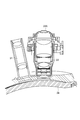
- Prior art date
- Legal status (The legal status is an assumption and is not a legal conclusion. Google has not performed a legal analysis and makes no representation as to the accuracy of the status listed.)
- Ceased
Links
Images




Classifications
-
- G—PHYSICS
- G01—MEASURING; TESTING
- G01B—MEASURING LENGTH, THICKNESS OR SIMILAR LINEAR DIMENSIONS; MEASURING ANGLES; MEASURING AREAS; MEASURING IRREGULARITIES OF SURFACES OR CONTOURS
- G01B11/00—Measuring arrangements characterised by the use of optical techniques
- G01B11/26—Measuring arrangements characterised by the use of optical techniques for measuring angles or tapers; for testing the alignment of axes
-
- G—PHYSICS
- G01—MEASURING; TESTING
- G01N—INVESTIGATING OR ANALYSING MATERIALS BY DETERMINING THEIR CHEMICAL OR PHYSICAL PROPERTIES
- G01N21/00—Investigating or analysing materials by the use of optical means, i.e. using sub-millimetre waves, infrared, visible or ultraviolet light
- G01N21/17—Systems in which incident light is modified in accordance with the properties of the material investigated
-
- G—PHYSICS
- G01—MEASURING; TESTING
- G01N—INVESTIGATING OR ANALYSING MATERIALS BY DETERMINING THEIR CHEMICAL OR PHYSICAL PROPERTIES
- G01N21/00—Investigating or analysing materials by the use of optical means, i.e. using sub-millimetre waves, infrared, visible or ultraviolet light
- G01N21/17—Systems in which incident light is modified in accordance with the properties of the material investigated
- G01N21/55—Specular reflectivity
-
- G—PHYSICS
- G02—OPTICS
- G02B—OPTICAL ELEMENTS, SYSTEMS OR APPARATUS
- G02B21/00—Microscopes
- G02B21/24—Base structure
- G02B21/241—Devices for focusing
-
- G—PHYSICS
- G02—OPTICS
- G02B—OPTICAL ELEMENTS, SYSTEMS OR APPARATUS
- G02B21/00—Microscopes
- G02B21/24—Base structure
- G02B21/241—Devices for focusing
- G02B21/245—Devices for focusing using auxiliary sources, detectors
-
- G—PHYSICS
- G01—MEASURING; TESTING
- G01N—INVESTIGATING OR ANALYSING MATERIALS BY DETERMINING THEIR CHEMICAL OR PHYSICAL PROPERTIES
- G01N2201/00—Features of devices classified in G01N21/00
- G01N2201/06—Illumination; Optics
- G01N2201/063—Illuminating optical parts
- G01N2201/0633—Directed, collimated illumination
-
- G—PHYSICS
- G01—MEASURING; TESTING
- G01N—INVESTIGATING OR ANALYSING MATERIALS BY DETERMINING THEIR CHEMICAL OR PHYSICAL PROPERTIES
- G01N2201/00—Features of devices classified in G01N21/00
- G01N2201/10—Scanning
- G01N2201/104—Mechano-optical scan, i.e. object and beam moving
Definitions
- the present invention relates to a measuring device for measuring the inclination of a part of the sample as an index for defining the posture of the sample, an observation device including the measuring device, and a measuring method.
- Patent Document 1 a sample is irradiated with the irradiation light while scanning the irradiation position of the irradiation light output from the light source, and the detection signal from the photodetector that receives the light generated in the sample and the irradiation position of the irradiation light are disclosed.
- a measurement device that acquires a two-dimensional image (observation surface image) of a sample surface based on information on the above is described.
- the contact surface of the solid immersion lens and the surface of the sample It is important to make them parallel to each other. In this respect as well, it is important that the observation surface of the sample is perpendicular to the optical axis of the objective lens.
- the measuring apparatus disclosed in Patent Document 1 forms an image of reflected light generated when a sample is irradiated with irradiation light output from a light source on a light receiving surface of a two-dimensional optical imaging unit.
- the inclination of the observation surface of the sample with respect to the surface perpendicular to the optical axis of the objective lens is obtained, and the sample is observed so that the observation surface of the sample is perpendicular to the optical axis of the objective lens Adjust the tilt.
- Patent Document 1 needs to include an additional two-dimensional imaging unit, and additionally includes an optical system for guiding reflected light from the sample to the two-dimensional imaging unit. There is. Therefore, the manufacturing cost of the measuring device itself increases, and the cost required for adjusting the added optical system is also required.
- An object of the present invention is to provide a measuring device having a structure for easily adjusting the inclination of the observation surface, an observation device including the measuring device, and a measuring method.
- the measuring apparatus has a relay lens system that guides irradiation light to the light irradiation area in the observation surface of the sample, and measures the inclination of the light irradiation area with respect to a reference plane orthogonal to the optical axis of the relay lens system.
- the measurement apparatus includes at least a light source, a sample holder, a relay lens system, a scanner, a photodetector, and an analysis unit.
- the light source outputs irradiation light.
- the sample holder changes the inclination angle of the light irradiation region with respect to the reference plane while holding the sample.
- the relay lens system is arranged to face the sample holder.
- the scanner is disposed on the optical path between the light source and the relay lens system. Further, the scanner changes the emission angle of the irradiation light emitted from the relay lens system to the light irradiation region.
- the photodetector receives the reflected light that has passed through the relay lens system and the scanner, and outputs a detection signal corresponding to the reflected light.
- the analysis unit obtains the tilt information of the light irradiation region in the sample by associating the information regarding the emission angle of the irradiation light output from the scanner with the information regarding the signal value of the detection signal.
- the inclination of the sample can be easily adjusted so that the surface of the sample is perpendicular to the optical axis of the objective lens with a simple apparatus configuration.
- the measurement apparatus may be included in an observation apparatus that observes the sample surface via an objective lens system as one aspect thereof, and irradiates the light irradiation region within the observation surface of the sample. It has a relay lens system that guides, and measures the inclination of the light irradiation region with respect to a reference plane orthogonal to the optical axis of the relay lens system.
- the measurement apparatus includes at least a light source, a sample holder, a relay lens system, a scanner, a photodetector, and an analysis unit.
- the light source outputs irradiation light.
- the sample holder changes the inclination angle of the light irradiation region with respect to the reference plane while holding the sample.
- the relay lens system is arranged to face the sample.
- the scanner is disposed on the optical path between the light source and the relay lens system. Further, the scanner changes the emission angle (scan angle) of the irradiation light emitted from the relay lens system to the light irradiation region.
- the photodetector receives the reflected light that has passed through the relay lens system and the scanner, and outputs a detection signal corresponding to the reflected light.
- the analysis unit obtains the tilt information of the light irradiation region in the sample by associating the information regarding the emission angle of the irradiation light output from the scanner with the information regarding the signal value of the detection signal.
- the emission angle change of the irradiation light is changed by the lens facing the sample. It is possible to change the incident angle of the irradiation light reaching the sample without moving the system. Since the signal value of the detection signal of the reflected light from the sample depends on the incident angle of the irradiation light, by associating the output angle of the irradiation light by the scanner that determines the incident angle with the signal value, the simple device configuration Sample tilt information is obtained.
- the measurement apparatus may include a control unit.
- the control unit adjusts the posture of the sample holder based on the tilt information so that the propagation direction of the reflected light vertically reflected in the light irradiation region is parallel to the optical axis of the relay lens system. Since the propagation direction of the reflected light can be specified from the tilt information, it is possible to adjust the orientation of the sample holder based on the orientation of the sample holder when the tilt information is obtained.
- the analysis unit converts, as inclination information, information related to the emission angle of irradiation light output from the scanner into two-dimensional coordinates, and information on detection signals corresponding to the two-dimensional coordinates. May be generated to generate a two-dimensional image (laser scan image) including the tilt information of the sample.
- the photodetector may include a single-point photodetector.
- the single point photodetector is a point device that collects data for one pixel at a time (see, for example, Patent Document 2).
- the scanner may make the reflected light coincide with the light beam of the irradiation light.
- the measurement apparatus may include a first aperture disposed on the optical path between the scanner and the photodetector. This first aperture limits the beam size of the reflected light received by the photodetector.
- the measurement apparatus may include an optical fiber disposed on the optical path between the scanner and the photodetector. This optical fiber has an incident end for taking in reflected light, and an exit end from which reflected light propagated in the optical fiber is emitted toward the photodetector.
- the measurement apparatus may include a second diaphragm disposed on the optical path between the scanner and the relay lens system. This second diaphragm limits the beam size of the irradiation light incident on the relay lens system.
- the measurement apparatus preferably includes an objective lens system and a lens selection unit that holds at least the relay lens system and the objective lens system.
- the objective lens collects the irradiation light on the sample.
- the lens selection unit is arranged so that one of the relay lens system and the objective lens system faces the sample while holding at least the relay lens system and the objective lens system.
- the relay lens system may include an objective lens system disposed so as to face the sample, and a lens system that forms the relay optical system with the objective lens system. Good.
- the lens system is disposed on the optical path between the objective lens system and the scanner.
- the measurement apparatus may include a solid immersion lens.
- the observation apparatus includes, as one aspect thereof, a measurement apparatus having the above-described structure, and the observation surface of the sample whose inclination is corrected by the measurement apparatus is referred to as a relay lens system. Observation is performed through a different objective lens or an objective lens constituting a part of the relay lens system.
- the irradiation light is guided to the light irradiation region of the sample through the lens system, and the inclination of the light irradiation region with respect to the reference plane orthogonal to the optical axis of the lens system is measured.
- the measurement method includes at least a holding step, a focus adjustment step, a relay lens system placement step, an irradiation step, a detection step, and a tilt measurement step.
- the holding step the sample is held by the sample holder that changes the inclination of the light irradiation region with respect to the reference plane while holding the sample.
- the focus adjustment step the focus position of the lens system is adjusted on the light irradiation area.
- a relay lens system is arranged as a lens system so as to face the sample.
- the sample is irradiated with irradiation light from the relay lens system toward the light irradiation region.
- the irradiation light is output from the relay lens system to the light irradiation region by outputting the irradiation light while changing the emission angle (scan angle) from the scanner arranged on the propagation path of the irradiation light.
- the sample is irradiated with irradiation light while changing the incident angle.
- the reflected light reflected by the light irradiation region is received and a detection signal corresponding to the reflected light is output.
- the tilt information of the light irradiation region in the sample is obtained by associating the information of the emission angle of the irradiation light output from the scanner with the information of the detection signal.
- the measurement method may further include an inclination adjustment step.
- the tilt adjustment step is based on tilt information (including information on the propagation direction of the reflected light) so that the propagation direction of the reflected light vertically reflected in the light irradiation region is parallel to the optical axis of the relay lens system. Adjust the posture of the sample holder.
- the inclination measurement step and the inclination adjustment step may be repeatedly performed while reducing the change width of the incident angle of the irradiation light reaching the light irradiation region from the relay lens system.
- the measurement method may include a pretilt measurement step.
- the pre-tilt measurement step is a step of obtaining a deviation between the propagation direction of the reflected light vertically reflected in the light irradiation region and the optical axis of the relay lens system before the focus adjustment step.
- the posture of the sample holder with respect to the reference plane is adjusted so that the obtained deviation is reduced.
- the focus adjustment step adjusts the focus position of the objective lens on the light irradiation region in a state where the objective lens is arranged as a lens system.
- the inclination measurement step converts, as inclination information, information related to the emission angle of irradiation light into two-dimensional coordinates, and plots detection signal information corresponding to the two-dimensional coordinates.
- a two-dimensional image laser scan image
- the tilt information of the sample may be generated.
- the measurement method is configured such that, before the focus adjustment step, the propagation direction of the reflected light reflected perpendicularly in the light irradiation region and the optical axis of the relay lens system coincide with each other. There may be provided a pre-adjustment step.
- each aspect listed in this [Description of Embodiments of the Invention] is applicable to each of all the remaining aspects or to all combinations of these remaining aspects. .
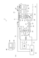
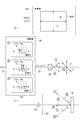
- FIG. 1 to 3 are diagrams showing a configuration of a measurement apparatus 1 (included in the observation apparatus according to the present embodiment) 1 according to the first embodiment.
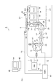
- FIG. 1 is a diagram illustrating a configuration in which a relay lens system 31 is arranged on the optical path of irradiation light in the measurement apparatus 1.
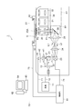
- FIG. 2 is a diagram illustrating a configuration in which the objective lens system 32 is arranged on the optical path of the irradiation light in the measurement apparatus 1.
- FIG. 3 is a diagram showing a configuration in which the objective lens system with a solid immersion lens (objective lens system having the solid immersion lens 33A) 33 is arranged on the optical path of the irradiation light in the measurement apparatus 1.
- the measuring apparatus 1 includes a light source 11, an optical fiber 12, a collimating lens 13, a polarizing beam splitter 21, a ⁇ / 4 plate 22, a scanner 23, lenses 24 and 25, a mirror 26, a relay lens system 31, an objective lens system 32, and an objective lens.
- System 33, solid immersion lens 33A, revolver 34, lens 41, first diaphragm 42, photodetector (first photodetector) 44, sample holder 51, actuators 52 and 53, control unit 61, analysis unit 62, An input unit 63 and a display unit 64 are provided.
- the optical unit A1 is configured by the mirror 26 together with the relay lens system 31, the objective lens system 32, and the objective lens system 33 held by the revolver 34.
- the optical unit A1 includes an auxiliary unit B1 configured by the mirror 26.
- the actuators 52 and 53 change the inclination of the sample holder 51 along the direction orthogonal to each other (inclination control direction).
- an optical fiber 12 As an irradiation optical system for guiding the irradiation light L1 output from the light source 11 to the sample S, an optical fiber 12, a collimator lens 13, a polarizing beam splitter 21, and ⁇ / 4 are provided on the optical path of the irradiation light L1 from the light source 11 toward the sample S.
- a plate 22, a scanner 23, lenses 24 and 25, and a mirror 26 are arranged in this order. These are optically coupled to each other.
- a detection optical system that guides the reflected light L2 reflected by the sample S to the detection position, that is, the photodetector 44, a mirror 26, lenses 25, 24,
- a scanner 23, a ⁇ / 4 plate 22, a polarizing beam splitter 21, a lens 41, and a first aperture 42 are arranged in this order.
- a Faraday rotator that outputs the polarization plane of incident light after rotating it by 22.5 degrees or 45 degrees, for example, may be arranged.
- a half mirror may be arranged in place of the polarization beam splitter 21 except for the ⁇ / 4 plate 22.
- Sample S is, for example, a semiconductor device, and examples of the semiconductor device include an integrated circuit having a PN junction such as a transistor, a high-current / high-voltage MOS transistor and a bipolar transistor, and a power semiconductor element (power device).
- the sample S may be a package including a semiconductor device, a composite substrate, or the like.
- Examples of the integrated circuit having a PN junction such as a transistor include a small scale integrated circuit (SSI: Small Scale Integration), a medium scale integrated circuit (MSI: Medium Scale Scale Integration), and a large scale integrated circuit (LSI: Large Scale Scale Integration).
- a tester unit (not shown) may be electrically connected to the semiconductor device via a device control cable, and a predetermined modulation current signal (stimulation signal) may be applied.
- the sample holder 51 is a device having a structure for holding the sample S and adjusting the posture of the sample S.
- the sample holder 51 is a stage on which the sample S is placed. The inclination of the sample mounting surface of the sample holder 51 is variable.
- the inclination of the sample mounting surface of the sample holder 51 may be adjusted by the actuators 52 and 53 driven by the control unit 61, or may be adjusted by manual operation.
- tilt control in the sample holder 51 the tilt of the observation surface of the sample S (light irradiation region where the irradiation light L1 reaches) can be adjusted.
- the light source 11 outputs irradiation light L1 to be irradiated to the sample S held by the sample holder 51.
- the light source 11 is driven by a power source (not shown), and outputs CW light or pulsed light applied to the sample S.
- the light output from the light source 11 may be incoherent (non-coherent) light or coherent light such as laser light.
- SLD Super Luminescent Diode
- ASE Amplified Spontaneous Emission
- LED Light Emitting Diode
- a solid-state laser light source, a semiconductor laser light source, or the like is applicable.
- the optical fiber 12 inputs the irradiation light L1 output from the light source 11 to the incident end, and outputs the irradiation light L1 propagated through the optical fiber 12 to the collimating lens 13 through the emission end.
- the collimating lens 13 receives the irradiation light L1 output as diverging light from the output end of the optical fiber 12, and outputs the irradiation light L1 as parallel light (collimating light).
- the polarization beam splitter 21 receives the irradiation light L1 output from the collimating lens 13, reflects the S-polarized component of the irradiation light L1, and outputs it to the ⁇ / 4 plate 22.
- the ⁇ / 4 plate 22 receives the linearly polarized irradiation light L1 output from the polarization beam splitter 21, and outputs the irradiation light L1 to the scanner 23 as circularly polarized light.
- the scanner 23 receives the irradiation light L1 output from the ⁇ / 4 plate 22, and outputs the irradiation light L1 to the lens 24.
- the scanner 23 can change the output direction (exit angle) of the irradiation light L1.
- the emission angle of the irradiation light L1 from the scanner 23 is defined by the angle formed by the optical axis of the lens 24 arranged facing the scanner 23 and the emission direction of the irradiation light L1.
- the output direction of the light L1 is swung around the optical axis of the lens 24.
- the scanner 23 includes, for example, a galvanometer mirror, a polygon mirror, and a MEMS (micro electro mechanical system) mirror.
- the lenses 24 and 25 and the mirror 26 project the position of the mirror in the scanner 23 to a predetermined position (pupil position P1). Therefore, at the pupil position P1, the propagation direction of the irradiation light L1 changes without changing the position of the principal ray.
- the propagation direction of the irradiation light L1 at the pupil position P1 is changed by the action of the scanner 23.
- the scanner 23 can scan the irradiation light L1 on the sample S without moving the objective lens system.
- the irradiation light L1 whose propagation direction has been changed by the scanner 23 passes through the objective lens system 32 or the objective lens system 33 and is scanned as spot light on the sample S.
- the relay lens system 31, the objective lens system 32, and the objective lens system 33 are held by a revolver 34, and a lens system selected from these is placed on the optical path between the mirror 26 and the sample S by the revolver 34. It arrange
- the irradiation light L1 output from the scanner 23 passes through the lenses 24 and 25, then is reflected by the mirror 26, passes through the pupil position P1, passes through one of the selected lens systems, and finally reaches the sample S.
- the observation position P2 is irradiated.
- the objective lens system 33 may include a solid immersion lens 33A fixed at the tip.
- the reflected light L2 generated in the sample S in response to the irradiation of the irradiation light L1 reaches the polarization beam splitter 21 by following the same path as the irradiation light L1 in the reverse direction. Due to the descanning action by the scanner 23, the principal rays of the irradiation light L ⁇ b> 1 and the reflected light L ⁇ b> 2 coincide with each other between the polarization beam splitter 21 and the scanner 23.
- the ⁇ / 4 plate 22 outputs the reflected light L2 to the polarization beam splitter 21 as P-polarized light.
- the polarization beam splitter 21 receives the reflected light L2 output from the ⁇ / 4 plate 22, transmits the P-polarized component of the reflected light L2, and outputs the transmitted P-polarized component to the lens 41.
- the lens 41 condenses the reflected light L2 output from the polarization beam splitter 21.
- the first diaphragm 42 has an opening at a position where light is collected by the lens 41, and allows a component that has reached the opening portion of the reflected light L ⁇ b> 2 collected by the lens 41 to pass therethrough.
- the photodetector 44 receives the reflected light L2 that has passed through the opening of the first diaphragm 42, and outputs a detection signal corresponding to the optical power (light intensity).
- the photodetector 44 may be a single point photodetector (see Patent Document 2 above), and for example, a photodiode, an avalanche photodiode, a photomultiplier tube, or the like is suitable.
- the polarization beam splitter 21, the lens 41, the first diaphragm 42, and the photodetector 44 are optically coupled.
- the control unit 61 is electrically connected to the light detector 44 via the sensor cable 71 and inputs a detection signal output from the light detector 44.
- the control unit 61 is electrically connected to the analysis unit 62 via the control cable 72, transmits / receives various signals to / from the analysis unit 62, and inputs instructions from the analysis unit 62.
- the control unit 61 is connected to the actuators 52 and 53 via the control cable 73, and controls the actuators 52 and 53, whereby the inclination of the sample holder 51, that is, the inclination of the sample S held by the sample holder 51 is controlled. adjust.
- the control unit 61 is connected to the scanner 23 via the control cable 74, and controls the scanning operation of the irradiation light L1 by the scanner 23.
- the control unit 61 is, for example, a lock-in amplifier, a spectrum analyzer, a digitizer, or a cross domain analyzer (registered trademark) as an electrical measurement unit (not shown) that is electrically connected to the photodetector 44 or the tester unit. ), A network analyzer may be provided.
- the analysis unit 62 is a computer, for example, and is used together with the input unit 63 and the display unit 64.
- the analysis unit 62 includes a CPU (Central Processing Unit) as a processor, a RAM (Random Access Memory) or a ROM (Read Only Memory) as a recording medium, and an input / output module.
- the analysis unit 62 is electrically connected to the input unit 63 and the display unit 64 by an input / output module.
- the analysis unit 62 reads a program or the like on hardware such as a CPU and a RAM, so that the CPU propagates the irradiation light L1 at the pupil position P1 by the scanner 23 (depending on the emission angle of the irradiation light L1 at the scanner 23).
- the input unit 63 is, for example, a keyboard or a mouse, and inputs a measurement start instruction, an instruction regarding measurement conditions, and the like.
- the display unit 64 is, for example, a display that displays measurement conditions or displays an observation surface image (two-dimensional image) of the sample S.
- the relay lens system 31 selected by the revolver 34 is arranged between the mirror 26 and the sample S so as to face the sample S.
- the objective lens system 32 selected by the revolver 34 is arranged between the mirror 26 and the sample S so as to face the sample S.
- the objective lens system 33 with a solid immersion lens selected by the revolver 34 is arranged between the mirror 26 and the sample S so as to face the sample S.
- the objective lens systems 32 and 33 are positioned at the pupil position P1 by the irradiation optical system.
- the irradiation light L1 that has reached as parallel light is condensed at a position on the sample S corresponding to the propagation direction of the irradiation light L1 at the pupil position P1.
- the condensing position (light irradiation position) of the irradiation light L 1 in the sample S is scanned by the action of the scanner 23.
- a part of the reflected light L2 reflected at the condensing position passes through the detection optical system, passes through the opening portion of the first diaphragm 42, and is received by the photodetector 44.
- the optical system between the condensing position of the irradiation light L1 in the sample S and the opening of the first diaphragm 42 constitutes a confocal optical system.
- the analysis unit 62 receives the detection signal output from the light detector 44 via the control unit 61, and the detection signal value and the condensing position of the irradiation light L ⁇ b> 1 on the sample S by the scanner 23 (irradiation in the scanner 23). Based on the emission angle of the light L1), a two-dimensional laser scan image including the tilt information of the sample S can be generated.
- the relay lens system 31 uses the irradiation light L1 that has reached the pupil position P1 as parallel light by the irradiation optical system, and the irradiation light L1 at the pupil position P1.
- the sample S is irradiated as parallel light along a direction corresponding to the propagation direction of.
- the irradiation direction of the irradiation light L ⁇ b> 1 on the sample S is scanned by the scanner 23.
- the incident angle of the irradiation light L1 on the sample S is defined by the angle formed by the irradiation direction of the irradiation light L1 on the sample S and the normal line of the light irradiation region on the sample S. Even if this irradiation direction changes, the irradiation range of the irradiation light L1 to the sample S does not change. Even if the reflected light L2 reflected by the sample S reaches the first aperture 42 via the detection optical system in response to the irradiation of the irradiation light L1 to the sample S, the first of the reflected light L2 that has reached the first diaphragm 42.
- the analysis unit 62 receives the detection signal output from the photodetector 44, and the detection signal value and the irradiation direction of the irradiation light L1 to the sample S by the scanner 23 (depending on the emission angle of the irradiation light L1 in the scanner 23). Based on the above, a laser scan image including the tilt information of the sample S can be generated.
- the laser scan image generated at this time is not an observation surface image of the sample S, but a two-dimensional image representing the incident angle of the irradiation light L1 on the sample S (depending on the emission angle of the irradiation light L1 in the scanner 23), that is, 4 is an image including inclination information of a sample S.
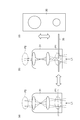
- FIG. 4 is a diagram for explaining a state of propagation of the irradiation light L1 when the relay lens system 31 is arranged on the optical path of the irradiation light L1 in the measurement apparatus 1 according to the first embodiment.
- the irradiation light L1 that has reached the pupil position P1 as parallel light by the irradiation optical system is directed by the relay lens system 31 according to the propagation direction of the irradiation light L1 at the pupil position P1. Is irradiated to the observation position P2 as parallel light.
- the observation position P2 where the irradiation light L1 is irradiated on the sample S is not changed.
- the spot size of the irradiation light L1 irradiated to the observation position P2 of the sample S is a size obtained by multiplying the beam size of the irradiation light L1 at the pupil position P1 by the relay magnification of the relay lens system 31.
- the beam size of the irradiation light L1 reaching the pupil position P1 is larger than the visual field size to be observed by the objective lens systems 32 and 33 in the sample S.
- the spot size of the irradiation light L1 irradiated to the observation position P2 of the sample S is the visual field size to be observed in the sample S. Become bigger. As a result, light generated outside the field of view may affect the measurement results.
- the beam size of the irradiation light L1 passing through the second diaphragm 35 can be reduced, and the spot size of the irradiation light L1 irradiated to the observation position P2 of the sample S can be reduced.
- the spot size of the irradiation light L1 irradiated to the observation position P2 can be made the same as or smaller than the visual field size (for example, 1 to 2 mm) to be observed by the objective lens systems 32 and 33. .
- the second diaphragm 35 is preferably detachable. As shown in FIG. 4C, the second diaphragm 35 preferably has a plurality of openings having different diameters. In this case, the beam size of the irradiation light L1 passing through the second diaphragm 35 can be changed by selecting any one of the plurality of openings.
- the second diaphragm 35 is inclined with respect to a plane perpendicular to the optical axis of the relay lens system 31.
- the surface of the second diaphragm 35 is subjected to an antireflection treatment.
- the size of the change range of the incident angle of the irradiation light L1 to the observation position P2 is inversely proportional to the relay magnification of the relay lens system 31. Therefore, it is preferable that the relay magnification of the relay lens system 31 is selected according to the size of the adjustable range of the incident angle of the irradiation light L1 to the observation position P2.
- the optical unit A1 shown in FIGS. 1 to 3 includes a relay lens system 31, an objective lens system 32, and a configuration in which the objective lens system 33 is held by a revolver 34, and an auxiliary unit B1.
- the lens system may be configured using the objective lens system 32. That is, instead of the optical unit A1, the optical unit A2 shown in FIG. 5A may be employed in the measuring apparatus 1 shown in FIGS.
- FIG. 5A and FIG. 5B are diagrams showing configurations of modifications of the optical unit A1 and the auxiliary unit B1 that constitute a part of the first and second embodiments.
- the 5A includes an objective lens system 32, a configuration in which the objective lens system 33 is held by a revolver 34, and an auxiliary unit B2 in place of the auxiliary unit B1 configured by the mirror 26.
- the auxiliary unit B2 includes a third diaphragm 260 that allows a part of the irradiation light L1 from the lens 25 to pass through, the mirror 26, the objective lens system 32, and a lens system 261 that constitutes a relay optical system (for example, the objective lens system 32). Conjugated conjugate lens system).
- the lens system 261 included in the auxiliary unit B2 and the objective lens system 32 constitute a relay lens system 31A.
- the auxiliary unit B3 shown in FIG. 5B will be described later.
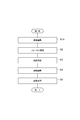
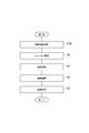
- FIG. 6 is a flowchart for explaining the measurement method according to the present embodiment.
- the measurement method according to the present embodiment is a method for generating an observation surface image of the sample S using the measurement device 1.
- the measurement method according to the present embodiment includes a pre-adjustment step S1A, a focus adjustment step S2, an inclination measurement step S3, an inclination adjustment step S4, and an image acquisition step S5.
- the sample S is held by the sample holder 51 whose inclination of the mounting surface is variable (holding step).
- the center of the propagation direction change of the irradiation light L1 at the pupil position P1 by the scanner 23 and the optical axis of the objective lens (lens system facing the sample S) are made to coincide with each other.
- the center of the scan range of the irradiation light L1 output from the scanner 23 is adjusted by adjusting the scan range by the scanner 23 and the adjustment of the irradiation optical system of the lens 24 (lens directly facing the emission side of the scanner 23). Match the optical axis.
- this pre-adjustment step S1A is performed. There is no need.
- the irradiation optical system has an adjustment error or the like, it is preferable to perform this pre-adjustment step S1A.
- the irradiation light L1 is output from the light source 11 in a state where the objective lens system 32 or the objective lens system 33 selected by the revolver 34 is arranged on the optical path of the irradiation light L1, and the selected objective is selected.
- the focus position of the lens is adjusted to coincide with the sample S. Such adjustment of the focus position is performed by moving the sample holder 51 or the revolver 34 in a direction parallel to the optical axis of the objective lens.
- the relay lens system 31 selected by the revolver 34 as the lens system facing the sample S is placed on the optical path of the irradiation light L1 (relay lens placement step).
- the irradiation light L1 output from the light source 11 is output to the sample S from the relay lens system 31 disposed on the optical path of the irradiation light L1 by the revolver 34 (irradiation step).
- the reflected light L2 generated in response to the irradiation of the irradiation light L1 on the sample S is detected by the photodetector 44 (detection step).
- the detection signal (the optical power of the reflected light L2) output from the photodetector 44 and the emission angle of the irradiation light L1 output from the scanner 23 (the scan center coincident with the optical axis of the lens 24 and the emission of the irradiation light L1).
- the analysis unit 62 generates a laser scan image including the tilt information of the sample S based on the scan angle defined by the angle formed with the direction, and the observation surface (irradiation light L1) of the sample S based on the laser scan image.
- the inclination of the light irradiation region where the light reaches (inclination measurement step S3).
- the sample holder 51 is tilted so that the irradiation light L1 enters the observation surface of the sample S from the relay lens system 31 vertically based on the tilt information of the sample S obtained in the tilt measurement step S3. Adjusted.
- the inclination of the sample holder 51 may be adjusted by the actuators 52 and 53 driven by the control unit 61, or may be adjusted by manual operation.
- the irradiation light L1 is output from the light source 11 and reflected from the sample S in a state where the objective lens system 32 or the objective lens system 33 selected by the revolver 34 is arranged on the optical path of the irradiation light L1.
- the light L2 is received by the photodetector 44. Then, based on the detection signal output from the photodetector 44 and the emission angle information of the irradiation light L1 from the scanner 23, the analysis unit 62 generates an observation surface image of the sample S.
- the inspection step of the sample S may be performed.
- the irradiation light L1 is output from the light source 11 while the modulated current signal is applied to the sample S from the tester unit, and the reflected light L2 from the sample S is received by the photodetector 44.
- the electrical measurement unit performs measurement, and outputs the measurement signal as the measurement result To do.
- the sample S is inspected by analyzing the measurement signal by the analysis unit 62.
- This inspection step may be performed before the image acquisition step S5 for acquiring the observation surface image of the sample S via the objective lens system 32 or the objective lens system 33, or after the image acquisition step S5. Also good. Since this optical probing technique can be performed with almost the same optical system as tilt measurement and image acquisition, it is possible to perform from the angle adjustment to the inspection of the sample S without complicating the apparatus configuration.
- FIG. 7 is a conceptual diagram for explaining generation of inclination information in the inclination measurement step S3.
- the analysis unit 62 sets a scan range around the optical axis of the lens 24 as scan control for the scanner 23 in the control unit 61 via the control cable 72.
- the control unit 61 outputs a control signal for controlling the emission angle (scan angle) ⁇ of the irradiation light L ⁇ b> 1 output through the control cable 74 to the scanner 23.
- the emission angle ⁇ is defined by an HV orthogonal coordinate system that is on a plane orthogonal to the optical axis of the lens 24 located at the center of the scanning range and that has the origin at the position through which the optical axis passes.
- the irradiation light L1 is output while changing the emission angle ⁇ ( ⁇ H , ⁇ V ) from the scanner 23, and the observation surface is set perpendicular to the optical axis of the facing lens system.
- the irradiation light L1 is displayed by symbols 1 to 3 (hereinafter simply referred to as symbols 1 to 3) in which a plurality of light beams having different emission angles ⁇ (each irradiation light L1) is circled.
- the reflected light L2 from the sample S also includes symbols 1 ′ to 3 ′ (hereinafter simply referred to as symbols 1 ′ to 3 ′) in which a plurality of light beams (each reflected light L2) reflected in different directions are circled. Is displayed).
- symbols 1 ′ to 3 ′ a plurality of light beams (each reflected light L2) reflected in different directions are circled. Is displayed).
- the reflected light L2 reflected on the observation surface of the sample S is represented by symbol 1 ′ (a reflection component of the irradiation light L1 indicated by symbol 1), symbol 2 ′ (reflection of the irradiation light L1 indicated by symbol 2) Component), 3 ′ (the reflection component of the irradiation light L1 indicated by symbol 2).
- the photodetector 44 receives the reflected light L2 indicated by symbols 1 ′ to 3 ′, and outputs a detection signal Ps corresponding to the optical power of the reflected light L2 to the control unit 61. Specifically, since the emission angle ⁇ of the irradiation light L1 output from the scanner 23 changes with time, the detection signal Ps of the reflected light L2 indicated by the symbols 1 ′ to 3 ′ changes with time in the emission angle ⁇ . Is the optical power of the reflected light L2 at the sampling times T 1 , T 2 , T 3 corresponding to.
- the control unit 61 outputs the information ⁇ (T) and the detection signal Ps (T) regarding the emission angle ⁇ thus given as a time function to the analysis unit 62 via the control cable 72.
- the analysis unit 62 prepares a two-dimensional matrix corresponding to the HV orthogonal coordinate system, and detects the detection signal Ps (T) from the photodetector 44 at the coordinates corresponding to the information ⁇ (T) of the prepared two-dimensional matrix. ) Is plotted to generate a two-dimensional laser scan image 620 including the tilt information of the sample S.
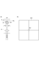
- FIG 8 and 9 are diagrams for explaining the inclination measurement step S3 in the measurement method according to the present embodiment.
- the irradiation light L1 is relayed along the direction D1 parallel to the optical axis AX of the relay lens system 31 with respect to the sample S whose observation surface coincides with the reference plane RS. It is output from the lens system 31.
- the irradiation light L1 output from the relay lens system 31 is perpendicularly incident on the surface (observation surface) of the sample S.
- the reflected light (regularly reflected light) L2 vertically reflected by the sample S propagates along the direction D2 parallel to the optical axis AX, and is received by the photodetector 44 through the detection optical system.
- the irradiation light L1 vertically enters the surface of the sample S from the relay lens system 31 when the propagation direction of the irradiation light L1 at the pupil position P1 is located at the center of the scan range. Therefore, as shown in FIG. 8B, the intensity is highest at the center position of the two-dimensional laser scan image 620 generated by the analysis unit 62 (position corresponding to the origin of the HV orthogonal coordinate system). A spot 621 is generated by the reflected light L2.
- Irradiation light L1 is output from the relay lens system 31.
- the irradiation light L1 output from the relay lens system 31 is perpendicularly incident on the surface (observation surface) of the sample S.
- the reflected light (specularly reflected light) L2 vertically reflected by the sample S propagates along a direction D2 that is not parallel to the optical axis AX, and reaches the first diaphragm 42 via the detection optical system.
- the reflected light L 2 that has passed through the opening of the first diaphragm 42 is received by the photodetector 44.
- the irradiation light L1 vertically enters the surface of the sample S from the relay lens system 31 when the propagation direction of the irradiation light L1 at the pupil position P1 is different from the center of the scan range. Therefore, as shown in FIG. 9B, the intensity is highest at a position different from the center position of the two-dimensional laser scan image 620 generated by the analysis unit 62, and a spot 622 due to the reflected light L2 is formed.
- the tilt adjustment step S4 the tilt of the sample holder 51 is adjusted so that the spot 622 appearing in the laser scan image 620 is moved to the center position of the laser scan image 620 (the position of the spot 621).
- the spot position with the highest optical power is the center position of the laser scan image 620 (corresponding to the origin of the HV orthogonal coordinate system). If present, the observation surface of the sample S coincides with the surface perpendicular to the optical axis of the relay lens system 31. In the laser scan image 620, the farther the spot position is from the center position, the greater the inclination of the observation surface in the sample S. The inclination (inclination information) of the sample S can be obtained based on the spot in the laser scan image 620.
- the tilt adjustment step S4 the tilt of the sample holder 51 is adjusted so that the spot position becomes the center position in the two-dimensional laser scan image 620 (including the tilt information of the sample S) generated by the analysis unit 62.
- the tilt adjustment amount (tilt information) of the sample holder 51 is calculated based on the spot position in the laser scan image 620, and the sample holder 51 is tilted by the calculated tilt adjustment amount.
- the light includes the intersection (the focus position of the objective lens) between the optical axis AX of the relay lens system 31 and the observation surface of the sample S, and the light of the relay lens system 31.
- the angle (inclination angle ⁇ ) formed by the reference plane RS orthogonal to the axis AX and the observation surface of the sample S is an XY orthogonal coordinate system (X axis, Y axis) on the reference plane RS with the intersection point as the origin.
- X axis, Y axis The angle (inclination angle ⁇ ) formed by the reference plane RS orthogonal to the axis AX and the observation surface of the sample S is an XY orthogonal coordinate system (X axis, Y axis) on the reference plane RS with the intersection point as the origin.
- Each is given by ( ⁇ X , ⁇ Y ) when the inclination control directions of the actuators 52 and 53 are defined by parallel to the axis projected onto the reference plane RS.
- the analysis unit 62 can easily calculate the spot position ( ⁇ H , ⁇ V ) in the image 620.
- the control unit 61 controls the actuators 52 and 53 so that the inclination angle components ⁇ X and ⁇ Y approach 0 (inclinate the sample holder 51). As described above, the control unit 61 determines the sample holder so that the propagation direction of the reflected light vertically reflected on the observation surface of the sample S is parallel to the optical axis AX of the relay lens system 31 based on the tilt information. 51's posture is adjusted.
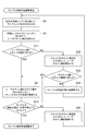
- steps S12 and S16 in this flowchart are steps for obtaining the inclination (inclination information) of the sample S based on the laser scan image generated by the analysis unit 62, as in the inclination measurement step S3.
- step S11 it is determined whether or not there is a spot in the two-dimensional laser scan image generated in the tilt measurement step S3.
- the process proceeds to the tilt adjustment step S4, and the tilt of the sample holder 51 is adjusted so that the irradiation light L1 is incident on the sample S from the relay lens system 31 vertically.
- step S11 the scan range of the scanner 23 is widened in step S12 to obtain a laser scan image, and in step S13, the presence or absence of a spot is determined in the laser scan image.
- step S12 the process proceeds to an inclination adjustment step S4, and the inclination of the sample holder 51 is adjusted so that the irradiation light L1 is incident on the sample S from the relay lens system 31 vertically. If no spot is confirmed in step S13, the installation angle of the sample S is readjusted in step S14, and then the focus adjustment step S2 is executed again.
- step S15 after the tilt adjustment step S4, it is determined whether or not the tilt angle ⁇ of the observation surface of the sample S is equal to or smaller than a predetermined angle (for example, ⁇ X and ⁇ Y are both 0.01 degrees). If it is determined in step S15 that the tilt angle of the sample S is not equal to or smaller than the predetermined angle, the scan range of the scanner 23 (change width in the propagation direction of the irradiation light L1 at the pupil position P1) is narrowed in step S16, thereby A laser scan image is acquired while narrowing the change range of the incident angle of the irradiation light L1 with respect to.
- a predetermined angle for example, ⁇ X and ⁇ Y are both 0.01 degrees.
- the process proceeds to an inclination adjustment step S4, and the inclination of the sample holder 51 is adjusted so that the irradiation light L1 enters the sample S from the relay lens system 31 vertically.
- the number of measurement points of the laser scan image be the same before and after the change width in the propagation direction of the irradiation light L1 is narrowed.
- FIG. 11 is a flowchart for explaining a measurement method according to another embodiment.
- the measurement method according to this embodiment is also a method for generating a two-dimensional observation surface image of the sample S using the measurement apparatus 1.
- the flowchart shown in FIG. 11 is different from the pre-adjustment step S1A in that it has a pre-tilt measurement step S1B, and the processing content of the tilt adjustment step S4. Is different.
- the relationship between the center of the change range of the propagation direction of the irradiation light L1 at the pupil position P1 by the scanner 23 and the optical axis of the objective lens (lens facing the sample S) is obtained.
- the degree of mismatch (error) is obtained.
- the inclination of the sample holder 51 is adjusted so that the irradiation light L1 enters the sample S from the relay lens system 31 vertically based on the relationship (error) obtained in the prior inclination measurement step S1B.
- FIG. 12 is a diagram for explaining the difference between the case where the relay lens system 31 is used as the lens system facing the sample S and the case where no lens system facing the sample S is used in the tilt measurement step S3. It is.
- the relay lens system 31 is used during the tilt measurement step S3 as in the present embodiment (FIG. 12A)
- the irradiation light L1 output from the relay lens system 31 changes in the incident direction to the sample S. However, it is incident on a common position in the sample S.
- the relay lens system 31 is not used (FIG. 12B)
- the incident light L1 output from the relay lens system 31 changes in the incident direction on the sample S
- the incident position on the sample S also changes. Change.
- the relay lens system 31 by using the relay lens system 31, it is possible to measure and adjust the inclination of the sample S at the position to be observed by the objective lens systems 32 and 33.
- the sample S is inclined so that the surface of the sample S is perpendicular to the optical axis of the objective lens systems 32 and 33 with a simple and inexpensive configuration in which the relay lens system 31 is simply mounted on the revolver 34. Can be adjusted easily.
- the relay lens system is configured by the objective lens system 32 and the objective lens system 32 and the lens system 261 as in the configuration shown in FIG.
- FIG. 13 is a diagram showing a configuration example of the relay lens system 31, the objective lens system 33 with a solid immersion lens, and the revolver.
- the diameter of the objective lens system 33 with a solid immersion lens is large, but the configuration of the relay lens system 31 is simple, and the diameter of the relay lens system 31 can be reduced. Therefore, the relay lens system 31 and the objective lens system 33 with a solid immersion lens can be attached to the adjacent sockets of the revolver 34 without interfering with each other.
- FIG. 14 is a diagram illustrating a configuration of a measurement apparatus (included in the observation apparatus according to the present embodiment) 2 according to the second embodiment.
- the measurement apparatus 2 of the second embodiment shown in FIG. Is different in that an optical fiber 43 is provided instead of the first diaphragm 42.
- the reflected light L2 generated by the irradiation of the irradiation light L1 on the sample S reaches the incident end of the optical fiber 43 through the detection optical system.
- the reflected light L 2 input from the incident end propagates through the optical fiber 43 and is output from the output end to the photodetector 44.
- the photodetector 44 receives the reflected light L2 output from the output end of the optical fiber 43, and outputs a detection signal corresponding to the optical power of the reflected light L2 to the control unit 61.
- the optical system located between the irradiation position of the irradiation light L1 in the sample S and the incident end of the optical fiber 43 constitutes a confocal optical system.
- the optical unit A1 including the auxiliary unit B1 is provided, and the same effects as in the first embodiment are achieved.
- the optical unit A1 is configured by an auxiliary unit B1 configured by a mirror 26 together with a relay lens system 31, an objective lens system 32, and an objective lens system 33 held by a revolver 34.
- the irradiation light L1 output from the light source 11 is output in a state where the objective lens system 32 or the objective lens system 33 selected by the revolver 34 is disposed on the optical path of the irradiation light L1,
- the focus position of the objective lens is adjusted to be on the sample S.
- the focus adjustment operation can be performed by methods other than those described above. For example, a positional relationship in which the focus position of the relay lens system 31 is on the sample S is obtained in advance. Further, when the relay lens system 31 is selected by the revolver 34, the focus adjustment can be performed by moving the sample holder 51 or the revolver 34 based on the positional relationship.
- the reflected light from the sample S is detected, and the tilt of the sample S is obtained based on the two-dimensional laser scan image generated by the analysis unit 62.
- the inclination of the sample S may be obtained by other procedures. For example, by monitoring the optical power detected by the photodetector 44 and the emission angle of the irradiation light L1 from the scanner 23, the inclination (inclination information) of the sample S may be obtained directly without creating a laser scan image.
- a semiconductor is held as the sample S, the sample holder 51 having a variable inclination, an optical system having the scanner 23 and the relay lens system 31, and the semiconductor is illuminated through the optical system.
- You may comprise the semiconductor inspection apparatus which test
- Such a modification can be realized by applying the auxiliary unit B3 shown in FIG. 5B instead of the auxiliary unit B1 to the optical unit A1 in the configurations of the first and second embodiments. is there.
- the auxiliary unit B3 includes a second photodetector 440 that can detect emission light generated from the semiconductor used as the sample S, and the mirror 26 can be switched, for example, by a movable mirror (in the direction indicated by the arrow R). By replacing the mirror 27 with a mirror 27 that can rotate along the axis, a semiconductor inspection apparatus is configured. By switching the movable mirror 27, the emission light generated in the sample S that has passed through the objective lens system 33 having the objective lens system 32 and the solid immersion lens 33A can be detected by the second photodetector 440. It can be performed.
- the second photodetector 440 is, for example, a camera equipped with a CCD (Charge-Coupled Device) image sensor or a CMOS (Complementary Metal-Oxide Semiconductor) image sensor, an InGaAs camera, or an MCT (Mercury-Cadmium-Telluride) camera. Similar to the photodetector (first photodetector) 44, the second photodetector 440 is electrically connected to the control unit 61 and controls the detection signal when the emission light generated in the semiconductor is detected. To the unit 61. The analysis unit 62 obtains an emission image based on the signal from the control unit 61, and the user can inspect the semiconductor.
- CCD Charge-Coupled Device
- CMOS Complementary Metal-Oxide Semiconductor
- DESCRIPTION OF SYMBOLS 1, 2 ... Measuring apparatus (included in observation apparatus) 11 ... Light source, 12 ... Optical fiber, 13 ... Collimating lens, 21 ... Polarizing beam splitter, 22 ... ⁇ / 4 plate, 23 ... Scanner, 24, 25 ... Lens , 26 ... mirror, 27 ... movable mirror, 31 and 31A ... relay lens system, 32 ... objective lens system, 33 ... objective lens system, 33A ... solid immersion lens, 34 ... revolver (lens selector), 35 ... second Aperture, 41 ... lens, 42 ... first aperture, 43 ... optical fiber, 44 ... photodetector (first photodetector), 51 ... sample holder, 52, 53 ...
- actuator 61 ... controller, 62 ... Analysis unit 63 ... Input unit 64 ... Display unit 71 ... Sensor cable 72-74 ... Control cable 260 ... Third aperture 261 ... Lens system 440 ... Second photodetector 620 ... Laser scanning Down image, 621, 622 ... spot, L1 ... irradiation light, L2 ... reflected light, P1 ... pupil position, P2 ... observation position, S ... sample, A1, A2 ... optical unit, B1, B2, B3 ... auxiliary unit.
Landscapes
- Physics & Mathematics (AREA)
- General Physics & Mathematics (AREA)
- Analytical Chemistry (AREA)
- Chemical & Material Sciences (AREA)
- General Health & Medical Sciences (AREA)
- Biochemistry (AREA)
- Life Sciences & Earth Sciences (AREA)
- Health & Medical Sciences (AREA)
- Immunology (AREA)
- Pathology (AREA)
- Optics & Photonics (AREA)
- Microscoopes, Condenser (AREA)
- Length Measuring Devices By Optical Means (AREA)
Abstract
Description
最初に本願発明の実施形態の内容をそれぞれ個別に列挙して説明する。
以下、本実施形態に係る測定装置、観察装置および測定方法の具体的な構造を、添付図面を参照しながら詳細に説明する。なお、本発明はこれらの例示に限定されるものではなく、請求の範囲によって示され、請求の範囲と均等の意味および範囲内での全ての変更が含まれることが意図される。また、図面の説明において同一の要素には同一符号を付して重複する説明を省略する。
図1~図3は、第1実施形態に係る測定装置(本実施形態に係る観察装置に含まれる)1の構成を示す図である。図1は、測定装置1において、リレーレンズ系31が照射光の光路上に配置された構成を示す図である。図2は、測定装置1において、対物レンズ系32が照射光の光路上に配置された構成を示す図である。図3は、測定装置1において、固浸レンズ付き対物レンズ系(固浸レンズ33Aを有する対物レンズ系)33が照射光の光路上に配置された構成を示す図である。
図14は、第2実施形態に係る測定装置(本実施形態に係る観察装置に含まれる)2の構成を示す図である。図1~図3に示された第1実施形態の測定装置1の構成(図5に示された変形例の構成を含む)と比較すると、図14に示される第2実施形態の測定装置2は、第1の絞り42に替えて光ファイバ43を備える点で相違する。
Claims (19)
- サンプルの光照射領域に照射光を導くリレーレンズ系を有し、前記リレーレンズ系の光軸に直交する基準平面に対する前記光照射領域の傾斜を測定する測定装置において、
前記照射光を出力する光源と、
前記サンプルを保持した状態で、前記基準平面に対する前記光照射領域の傾斜角を変えるサンプルホルダと、
前記サンプルホルダに対面するよう配置された前記リレーレンズ系と、
前記光源と前記リレーレンズ系との間の光路上に配置され、前記リレーレンズ系から出射される前記照射光の出射角を変化させるスキャナと、
前記リレーレンズ系および前記スキャナを通過した、前記光照射領域からの反射光を受光し、前記反射光に応じた検出信号を出力する光検出器と、
前記スキャナから出力された前記照射光の出射角に関する情報と前記検出信号の信号値に関する情報とを対応付けることにより、前記サンプルにおける前記光照射領域の傾斜情報を得る解析部と、
を備える測定装置。 - 前記傾斜情報に基づいて、前記光照射領域で垂直反射される反射光の伝搬方向が前記リレーレンズ系の光軸に対して平行となるように、前記サンプルホルダの姿勢を調整する制御部を更に備える、
請求項1に記載の測定装置。 - 前記解析部は、前記傾斜情報として、前記スキャナから出力された前記照射光の出射角に関する情報を二次元座標に変換し、前記二次元座標に対応する前記検出信号の情報をプロットしていくことにより、二次元のスキャン像を生成する、
請求項1または2に記載の測定装置。 - 前記光検出器は、シングルポイントの光検出器を含む、
請求項1~3の何れか一項に記載の測定装置。 - 前記スキャナは、前記反射光を前記照射光の光線に一致させる、
請求項4に記載の測定装置。 - 前記スキャナと前記光検出器との間の光路上に配置され、前記光検出器が受光する前記反射光のビームサイズを制限する第1の絞りを更に備える、
請求項1~5の何れか一項に記載の測定装置。 - 前記スキャナと前記光検出器との間の光路上に配置されるとともに、前記反射光を取り込むための入射端と、その内部を伝搬した前記反射光が前記光検出器へ向けて出射される出射端と、を有する光ファイバを更に備える、
請求項1~5の何れか一項に記載の測定装置。 - 前記スキャナと前記リレーレンズ系との間の光路上に配置され、前記リレーレンズ系に入射する前記照射光のビームサイズを制限する第2の絞りを更に備える、
請求項1~7の何れか一項に記載の測定装置。 - 前記サンプルに前記照射光を集光する対物レンズ系と、
少なくとも前記リレーレンズ系および前記対物レンズ系を保持した状態で、前記リレーレンズ系および前記対物レンズ系のうち何れかを前記サンプルに対面するように配置するレンズ選択部と、
を更に備える請求項1~8の何れか一項に記載の測定装置。 - 前記リレーレンズ系は、前記サンプルに対面するように配置された対物レンズ系と、前記対物レンズ系と前記スキャナとの間の光路上に配置された、前記対物レンズ系とリレー光学系を形成するレンズ系と、を含む、
請求項1~8の何れか一項に記載の測定装置。 - 固浸レンズを更に備える、
請求項1~10の何れか一項に記載の測定装置。 - 請求項1~11の何れか一項に記載の測定装置を含む観察装置。
- レンズ系を介してサンプルの光照射領域に照射光を導き、前記レンズ系の光軸に直交する基準平面に対する前記光照射領域の傾斜を測定する測定方法において、
前記基準平面に対する前記光照射領域の傾斜を変えるサンプルホルダに、前記サンプルを保持させる保持ステップと、
前記レンズ系のフォーカス位置を前記光照射領域上に調整するフォーカス調整ステップと、
前記レンズ系としてリレーレンズ系を前記サンプルに対面するよう配置するリレーレンズ系配置ステップと、
前記照射光の伝搬経路上に配置されたスキャナから出射角を変えながら前記照射光を出力させることにより、前記リレーレンズ系から前記光照射領域へ出射される前記照射光の入射角を変えながら、前記照射光を前記サンプルへ照射する照射ステップと、
前記光照射領域で反射された反射光を受光し、前記反射光に応じた検出信号を出力する検出ステップと、
前記スキャナから出力された前記照射光の出射角の情報と前記検出信号の情報とを対応付けることにより、前記サンプルにおける前記光照射領域の傾斜情報を得る傾斜測定ステップと、
を備える測定方法。 - 前記傾斜情報に基づいて、前記光照射領域で垂直反射される反射光の伝搬方向が前記リレーレンズ系の光軸に対して平行となるように、前記サンプルホルダの姿勢を調整する傾斜調整ステップを更に備える、
請求項13に記載の測定方法。 - 前記リレーレンズ系から前記光照射領域に出射される前記照射光の入射角の変化幅を縮小しながら、前記傾斜測定ステップおよび前記傾斜調整ステップを繰り返して行う、
請求項14に記載の測定方法。 - 前記フォーカス調整ステップの前に、前記光照射領域で垂直に反射された前記反射光の伝搬方向と前記リレーレンズ系の光軸とのズレを得る事前傾斜測定ステップを更に備え、
前記傾斜調整ステップは、前記ズレが低減されるよう、前記基準平面に対する前記サンプルホルダの姿勢を調整することを含む、
請求項14に記載の測定方法。 - 前記フォーカス調整ステップは、前記レンズ系として対物レンズが配置されている状態で、前記対物レンズのフォーカス位置を前記光照射領域上に調整することを含む、
請求項13~16の何れか一項に記載の測定方法。 - 前記傾斜測定ステップは、前記傾斜情報として、前記照射光の出射角に関する情報を二次元座標に変換し、前記二次元座標に対応する前記検出信号の信号値をプロットしていくことにより、二次元のスキャン像を生成する、
請求項13~17の何れか一項に記載の測定方法。 - 前記フォーカス調整ステップの前に、前記光照射領域で垂直に反射された前記反射光の伝搬方向と前記リレーレンズ系の光軸とを互いに一致させる事前調整ステップを更に備える、
請求項13~18の何れか一項に記載の測定方法。
Priority Applications (5)
| Application Number | Priority Date | Filing Date | Title |
|---|---|---|---|
| CN201780015582.2A CN108700411B (zh) | 2016-03-09 | 2017-03-07 | 测定装置、观察装置、及测定方法 |
| KR1020187020723A KR102278371B1 (ko) | 2016-03-09 | 2017-03-07 | 측정 장치, 관찰 장치 및 측정 방법 |
| JP2018504504A JP6813567B2 (ja) | 2016-03-09 | 2017-03-07 | 測定装置、観察装置および測定方法 |
| EP17763235.3A EP3428573B1 (en) | 2016-03-09 | 2017-03-07 | Measuring device, observing device and measuring method |
| US16/083,044 US11402200B2 (en) | 2016-03-09 | 2017-03-07 | Measuring device, observing device and measuring method |
Applications Claiming Priority (2)
| Application Number | Priority Date | Filing Date | Title |
|---|---|---|---|
| JP2016045442 | 2016-03-09 | ||
| JP2016-045442 | 2016-03-09 |
Publications (1)
| Publication Number | Publication Date |
|---|---|
| WO2017154895A1 true WO2017154895A1 (ja) | 2017-09-14 |
Family
ID=59789265
Family Applications (1)
| Application Number | Title | Priority Date | Filing Date |
|---|---|---|---|
| PCT/JP2017/008972 Ceased WO2017154895A1 (ja) | 2016-03-09 | 2017-03-07 | 測定装置、観察装置および測定方法 |
Country Status (7)
| Country | Link |
|---|---|
| US (1) | US11402200B2 (ja) |
| EP (1) | EP3428573B1 (ja) |
| JP (1) | JP6813567B2 (ja) |
| KR (1) | KR102278371B1 (ja) |
| CN (1) | CN108700411B (ja) |
| TW (1) | TWI716555B (ja) |
| WO (1) | WO2017154895A1 (ja) |
Cited By (3)
| Publication number | Priority date | Publication date | Assignee | Title |
|---|---|---|---|---|
| CN108819907A (zh) * | 2018-08-17 | 2018-11-16 | 广州智航电子科技有限公司 | 光雨量传感器及其工作方法 |
| WO2023002677A1 (ja) | 2021-07-19 | 2023-01-26 | 浜松ホトニクス株式会社 | 傾斜推定システム、傾斜推定方法、傾斜推定プログラム、半導体検査システム及び生体観察システム |
| US20230194383A1 (en) * | 2021-12-22 | 2023-06-22 | Abberior Instruments Gmbh | Apparatuses for Testing the lateral and Axial Confocality of a Scanning and Descanning Microscope Component Group |
Families Citing this family (5)
| Publication number | Priority date | Publication date | Assignee | Title |
|---|---|---|---|---|
| CN111344620B (zh) * | 2019-01-25 | 2024-02-13 | 敏捷焦点设计有限责任公司 | 用于宽场、共焦和多光子显微镜的动态聚焦和变焦系统 |
| WO2021173894A1 (en) * | 2020-02-28 | 2021-09-02 | Thrive Bioscience, Inc. | Pre-scan focus and scan focus methods |
| GB202105837D0 (en) * | 2021-04-23 | 2021-06-09 | ams Sensors Germany GmbH | Optical tilt sensor |
| CN114894712B (zh) * | 2022-03-25 | 2023-08-25 | 业成科技(成都)有限公司 | 光学量测设备及其校正方法 |
| CN115437195B (zh) * | 2022-09-30 | 2025-06-03 | 东华大学 | 一种智能验布机隧道光源 |
Citations (9)
| Publication number | Priority date | Publication date | Assignee | Title |
|---|---|---|---|---|
| JPH0972714A (ja) * | 1995-09-04 | 1997-03-18 | Toshiba Corp | 焦点調整装置 |
| US5705821A (en) * | 1996-11-07 | 1998-01-06 | Sandia Corporation | Scanning fluorescent microthermal imaging apparatus and method |
| JPH10239037A (ja) * | 1997-02-27 | 1998-09-11 | Nikon Corp | 観察装置 |
| JP2002014145A (ja) * | 2000-06-29 | 2002-01-18 | Hamamatsu Photonics Kk | 半導体デバイス検査装置及び半導体デバイス検査方法 |
| JP2003057169A (ja) * | 2001-08-13 | 2003-02-26 | Shiseido Co Ltd | 皮膚の三次元画像生成装置 |
| JP2004354345A (ja) * | 2003-05-30 | 2004-12-16 | Olympus Corp | 生体分子解析装置 |
| US20060028641A1 (en) * | 2004-08-09 | 2006-02-09 | Jonathan Frank | Light beam apparatus and method for orthogonal alignment of specimen |
| JP2008203034A (ja) * | 2007-02-19 | 2008-09-04 | Olympus Corp | 欠陥検出装置および欠陥検出方法 |
| JP2010216864A (ja) * | 2009-03-13 | 2010-09-30 | Olympus Corp | 測光装置 |
Family Cites Families (10)
| Publication number | Priority date | Publication date | Assignee | Title |
|---|---|---|---|---|
| US5896362A (en) * | 1996-07-26 | 1999-04-20 | Asahi Kogaku Kogyo Kabushiki Kaisha | Lens Inclination Adjustment System |
| US7028899B2 (en) | 1999-06-07 | 2006-04-18 | Metrologic Instruments, Inc. | Method of speckle-noise pattern reduction and apparatus therefore based on reducing the temporal-coherence of the planar laser illumination beam before it illuminates the target object by applying temporal phase modulation techniques during the transmission of the plib towards the target |
| US6677565B1 (en) * | 1998-08-18 | 2004-01-13 | Veeco Tucson Inc. | High speed autofocus and tilt for an optical imaging system |
| DE50210236D1 (de) * | 2001-03-06 | 2007-07-12 | Evotec Ag | Verfahren zur untersuchung chemischer und/oder biologischer proben |
| DE10127284A1 (de) * | 2001-06-05 | 2002-12-12 | Zeiss Carl Jena Gmbh | Autofokussiereinrichtung für ein optisches Gerät |
| US6621275B2 (en) | 2001-11-28 | 2003-09-16 | Optonics Inc. | Time resolved non-invasive diagnostics system |
| WO2006098443A1 (ja) * | 2005-03-17 | 2006-09-21 | Hamamatsu Photonics K.K. | 顕微鏡画像撮像装置 |
| JP4947774B2 (ja) | 2006-08-18 | 2012-06-06 | 富士フイルム株式会社 | 光波干渉測定装置および光波干渉測定方法 |
| WO2011093939A1 (en) * | 2010-02-01 | 2011-08-04 | Illumina, Inc. | Focusing methods and optical systems and assemblies using the same |
| GB201009039D0 (en) * | 2010-05-28 | 2010-07-14 | Nightingale Eos Ltd | Apparatus and method for compensating for sample misalignment |
-
2017
- 2017-03-07 WO PCT/JP2017/008972 patent/WO2017154895A1/ja not_active Ceased
- 2017-03-07 JP JP2018504504A patent/JP6813567B2/ja active Active
- 2017-03-07 EP EP17763235.3A patent/EP3428573B1/en active Active
- 2017-03-07 CN CN201780015582.2A patent/CN108700411B/zh active Active
- 2017-03-07 KR KR1020187020723A patent/KR102278371B1/ko active Active
- 2017-03-07 US US16/083,044 patent/US11402200B2/en active Active
- 2017-03-09 TW TW106107738A patent/TWI716555B/zh active
Patent Citations (9)
| Publication number | Priority date | Publication date | Assignee | Title |
|---|---|---|---|---|
| JPH0972714A (ja) * | 1995-09-04 | 1997-03-18 | Toshiba Corp | 焦点調整装置 |
| US5705821A (en) * | 1996-11-07 | 1998-01-06 | Sandia Corporation | Scanning fluorescent microthermal imaging apparatus and method |
| JPH10239037A (ja) * | 1997-02-27 | 1998-09-11 | Nikon Corp | 観察装置 |
| JP2002014145A (ja) * | 2000-06-29 | 2002-01-18 | Hamamatsu Photonics Kk | 半導体デバイス検査装置及び半導体デバイス検査方法 |
| JP2003057169A (ja) * | 2001-08-13 | 2003-02-26 | Shiseido Co Ltd | 皮膚の三次元画像生成装置 |
| JP2004354345A (ja) * | 2003-05-30 | 2004-12-16 | Olympus Corp | 生体分子解析装置 |
| US20060028641A1 (en) * | 2004-08-09 | 2006-02-09 | Jonathan Frank | Light beam apparatus and method for orthogonal alignment of specimen |
| JP2008203034A (ja) * | 2007-02-19 | 2008-09-04 | Olympus Corp | 欠陥検出装置および欠陥検出方法 |
| JP2010216864A (ja) * | 2009-03-13 | 2010-09-30 | Olympus Corp | 測光装置 |
Non-Patent Citations (1)
| Title |
|---|
| See also references of EP3428573A4 * |
Cited By (6)
| Publication number | Priority date | Publication date | Assignee | Title |
|---|---|---|---|---|
| CN108819907A (zh) * | 2018-08-17 | 2018-11-16 | 广州智航电子科技有限公司 | 光雨量传感器及其工作方法 |
| CN108819907B (zh) * | 2018-08-17 | 2024-02-20 | 广州智航电子科技有限公司 | 光雨量传感器及其工作方法 |
| WO2023002677A1 (ja) | 2021-07-19 | 2023-01-26 | 浜松ホトニクス株式会社 | 傾斜推定システム、傾斜推定方法、傾斜推定プログラム、半導体検査システム及び生体観察システム |
| KR20240035945A (ko) | 2021-07-19 | 2024-03-19 | 하마마츠 포토닉스 가부시키가이샤 | 경사 추정 시스템, 경사 추정 방법, 경사 추정 프로그램, 반도체 검사 시스템 및 생체 관찰 시스템 |
| US20230194383A1 (en) * | 2021-12-22 | 2023-06-22 | Abberior Instruments Gmbh | Apparatuses for Testing the lateral and Axial Confocality of a Scanning and Descanning Microscope Component Group |
| US12216019B2 (en) * | 2021-12-22 | 2025-02-04 | Abberior Instruments Gmbh | Apparatuses for testing the lateral and axial confocality of a scanning and descanning microscope component group |
Also Published As
| Publication number | Publication date |
|---|---|
| US20190101492A1 (en) | 2019-04-04 |
| KR102278371B1 (ko) | 2021-07-19 |
| KR20180121878A (ko) | 2018-11-09 |
| CN108700411B (zh) | 2023-04-21 |
| EP3428573A1 (en) | 2019-01-16 |
| US11402200B2 (en) | 2022-08-02 |
| TW201733905A (zh) | 2017-10-01 |
| JP6813567B2 (ja) | 2021-01-13 |
| EP3428573A4 (en) | 2019-10-30 |
| EP3428573B1 (en) | 2021-11-03 |
| TWI716555B (zh) | 2021-01-21 |
| JPWO2017154895A1 (ja) | 2019-01-10 |
| CN108700411A (zh) | 2018-10-23 |
Similar Documents
| Publication | Publication Date | Title |
|---|---|---|
| JP6813567B2 (ja) | 測定装置、観察装置および測定方法 | |
| JP6882209B2 (ja) | 半導体ウェハ上の高さを測定するための方法および装置 | |
| KR100743591B1 (ko) | 사이드 로브가 제거된 공초점 자가 간섭 현미경 | |
| JP6419893B1 (ja) | 半導体検査装置 | |
| JP2018054303A (ja) | 欠陥検出装置及び欠陥観察装置 | |
| KR101074560B1 (ko) | 현미경 및 시료 관찰 방법 | |
| CN106537133B (zh) | 检查装置及磁光晶体的配置方法 | |
| JPH11173946A (ja) | 光学的特性測定装置 | |
| WO2016047666A1 (ja) | 固浸レンズホルダ及び画像取得装置 | |
| US11967061B2 (en) | Semiconductor apparatus examination method and semiconductor apparatus examination apparatus | |
| JP2008191122A (ja) | 表面形状測定装置及び方法 | |
| JP2015008241A (ja) | ビア形状測定装置及びビア検査装置 | |
| JP2005017127A (ja) | 干渉計および形状測定装置 | |
| CN119223992A (zh) | 一种基于光谱成像的晶圆光致发光检测装置和方法 | |
| WO2022145391A1 (ja) | 走査型共焦点顕微鏡および走査型共焦点顕微鏡の調整方法 | |
| JP3754164B2 (ja) | 試料検査装置 | |
| JP2011118269A (ja) | 対物レンズの調整方法、対物レンズユニット、および表面検査装置 | |
| JP6909195B2 (ja) | 半導体検査装置 | |
| TW202548234A (zh) | 使用傾斜照明在接合樣品計量中之高對比度成像 | |
| US9417281B1 (en) | Adjustable split-beam optical probing (ASOP) | |
| JP2011123397A (ja) | 対物レンズユニットおよび表面検査装置 | |
| KR20180062559A (ko) | 패터닝 장치 및 이의 구동 방법 |
Legal Events
| Date | Code | Title | Description |
|---|---|---|---|
| ENP | Entry into the national phase |
Ref document number: 2018504504 Country of ref document: JP Kind code of ref document: A |
|
| ENP | Entry into the national phase |
Ref document number: 20187020723 Country of ref document: KR Kind code of ref document: A |
|
| NENP | Non-entry into the national phase |
Ref country code: DE |
|
| WWE | Wipo information: entry into national phase |
Ref document number: 2017763235 Country of ref document: EP |
|
| ENP | Entry into the national phase |
Ref document number: 2017763235 Country of ref document: EP Effective date: 20181009 |
|
| 121 | Ep: the epo has been informed by wipo that ep was designated in this application |
Ref document number: 17763235 Country of ref document: EP Kind code of ref document: A1 |