WO2017154819A1 - Dispositif de pesage combiné - Google Patents
Dispositif de pesage combiné Download PDFInfo
- Publication number
- WO2017154819A1 WO2017154819A1 PCT/JP2017/008720 JP2017008720W WO2017154819A1 WO 2017154819 A1 WO2017154819 A1 WO 2017154819A1 JP 2017008720 W JP2017008720 W JP 2017008720W WO 2017154819 A1 WO2017154819 A1 WO 2017154819A1
- Authority
- WO
- WIPO (PCT)
- Prior art keywords
- unit
- parameter
- coefficient
- control unit
- combination weighing
- Prior art date
Links
Images


Classifications
-
- G—PHYSICS
- G01—MEASURING; TESTING
- G01G—WEIGHING
- G01G19/00—Weighing apparatus or methods adapted for special purposes not provided for in the preceding groups
- G01G19/387—Weighing apparatus or methods adapted for special purposes not provided for in the preceding groups for combinatorial weighing, i.e. selecting a combination of articles whose total weight or number is closest to a desired value
- G01G19/393—Weighing apparatus or methods adapted for special purposes not provided for in the preceding groups for combinatorial weighing, i.e. selecting a combination of articles whose total weight or number is closest to a desired value using two or more weighing units
Definitions
- the present invention relates to a combination weighing device.
- the combination weighing device includes a conveyance unit that conveys an article, a plurality of hoppers that temporarily store articles conveyed by the conveyance unit, and a weighing that outputs a measurement value according to the mass of the article stored in each of the hoppers. And a control unit that selects a combination of measurement values from the plurality of measurement values output by the measurement unit so that the total value becomes the target measurement value, and causes the hopper corresponding to the combination to discharge the article. .
- the combination weighing device described in Patent Document 1 includes a parameter setting unit that sets a parameter for controlling the conveyance force of the conveyance unit.
- the control unit controls the conveyance force of the conveyance unit based on parameters set in the parameter setting unit.
- the article may adhere to the transport unit or the like. Therefore, the transport unit is appropriately cleaned.
- the transport unit is cleaned in a state where the operation of the combination weighing device is temporarily stopped.
- the state of the transport unit differs between before and after cleaning the transport unit. This is because, for example, an article attached to the transport unit is removed by cleaning. For this reason, if the transport unit after cleaning is controlled with the parameters immediately before the combination weighing device is temporarily stopped, control that is not suitable for the state of the transport unit is performed, and the operation efficiency decreases.
- the combination weighing device when an abnormality is found in the conveyance unit or the like, after the operation of the combination weighing device is temporarily stopped, the conveyance unit in which the abnormality is found is removed, and the other conveyance unit Exchanged.
- the transport unit after transport is controlled with the parameters immediately before the combination weighing device is temporarily stopped, control that is not suitable for the state of the transport unit after replacement is performed, and the operating efficiency decreases.
- One aspect of the present invention is a case where the control characteristics related to the operation of the member related to the operation of the own device have changed due to cleaning or replacement after the own device is temporarily stopped and before restarting.
- Another object of the present invention is to provide a combination weighing device that can be restarted without significantly reducing the operating efficiency after restarting compared to before suspension.
- a combination weighing device includes a plurality of conveyance units that convey an article, a plurality of hoppers that temporarily store articles conveyed by the conveyance unit, and masses of articles stored in each of the hoppers.
- the combination of the measurement values is selected so that the total value becomes the target measurement value from the measurement unit that measures the measurement value according to and the plurality of measurement values that are measured by the measurement unit and are respectively associated with the plurality of hoppers.
- a control unit that discharges articles to a hopper corresponding to the combination, a learning unit that updates a parameter for setting an operation of the transport unit by learning, and at least a part of parameters updated in the learning unit are stored
- a storage unit and the control unit stores the parameter updated in the learning unit in the storage unit and stores the parameter when the operation of the own device is temporarily stopped and then restarted.
- the parameters stored in the re-operation parameter is a different parameter and configuration parameters that were set to the operation of the transport unit immediately before being paused, is operated by setting the transport unit.
- the operation stored in the storage unit is set to the operation of the transport unit immediately before being temporarily stopped.
- a restart parameter which is a parameter different from the set parameter that has been set, is set in the transport unit and operated.
- the setting parameter is a parameter corresponding to a state in which, for example, the residue of the article is accumulated on the transport unit. For this reason, if the transport unit is controlled by the set parameter immediately before the temporary stop after the transport unit is washed, the transport unit transports the article with a parameter not suitable for the state of the transport unit.
- the transport unit is operated with a re-operation parameter different from the setting parameter immediately before being temporarily stopped. Therefore, for example, the transport unit can be controlled by parameters suitable for the transport unit after cleaning. Therefore, in the combination weighing device, since the articles are easily supplied to the hopper at the target weighing value, the combination is efficiently selected. As a result, in the combination weighing device, the control characteristics related to the operation of the member related to the operation of the own device have changed due to washing or replacement after the own device is temporarily stopped and before it is restarted. However, the operation efficiency after the restart can be restarted without significantly reducing the operation efficiency compared to before the temporary stop.
- an input unit that accepts at least an operation related to acquisition of a parameter set in the transport unit from an operator of the own apparatus is provided, and the control unit receives a parameter acquisition operation performed by the input unit. May be acquired and stored in the storage unit. In this configuration, parameters can be acquired at any timing of the operator.
- the information processing apparatus includes a display unit that displays information.
- the control unit acquires the restart parameter
- the control unit displays that the restart parameter is acquired on the display unit, and the display unit displays the restart parameter.
- the operation parameter may be set in the transport unit and operated. In this configuration, the operator can select whether to use the restart parameter. Therefore, control in accordance with the operator's sense is possible.
- the control unit when the ratio of the number of times the combination is established to the number of times the combination weighing is performed is an operation rate, the control unit sets a parameter that is set in the transport unit when the operation rate exceeds a predetermined value. May be acquired automatically and stored in the storage unit. In this configuration, efficient operation is possible by setting the predetermined value to, for example, 80% or more.
- control unit may automatically acquire a parameter set in the transport unit and store the parameter in the storage unit. In this configuration, since updated parameters are acquired by a plurality of learnings, efficient operation is possible.
- the control unit determines whether or not the characteristics of the transport unit have changed after the temporary stop and before restarting, and determines that the characteristics of the transport unit have changed as a result of the determination. If the restart parameter is acquired from the storage unit and it is determined that the characteristics of the transport unit have not changed, the setting parameter is acquired from the storage unit, and the restart parameter or the set parameter is set in the transport unit to operate. May be. In this configuration, for example, since a change in characteristics such as cleaning or replacement of the transport unit is automatically determined, it is possible to save the operator from inputting the change in characteristics.
- the control device when the operation of the own device is resumed after the operation of the own device is suspended from the operator of the own device, the control device includes an accepting unit that accepts an operation as to whether to use the setting parameter. If the operation of using the setting parameter is received in the storage unit, the setting parameter is acquired from the storage unit, and if the operation of not using the setting parameter is received in the receiving unit, the restart parameter is acquired from the storage unit, The setting parameter or the reactivation parameter may be set in the transport unit to operate. In this configuration, the operator can select use of the setting parameter or the restart parameter.
- the apparatus includes a receiving unit that receives an operation performed by an operator of the own device, and the control unit receives the signal indicating that the operation of the own device is temporarily stopped by cleaning through the receiving unit.
- the operator may be allowed to select whether or not to use the setting parameter when restarting. In this configuration, the operator can select use of the setting parameter.
- the control characteristics related to the operation of the member related to the operation of the own device change due to cleaning or replacement. Even if it exists, it can be restarted without significantly reducing the operating efficiency after the restart compared with before the temporary stop.
- FIG. 1 is a diagram illustrating a configuration of a combination weighing device according to an embodiment.
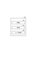
- FIG. 2 is a diagram illustrating a functional configuration of the control unit.
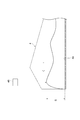
- FIG. 3 is a view showing the vicinity of the discharge end of the radiation feeder.
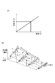
- FIG. 4A is a graph showing the relationship between the layer thickness and the supply amount
- FIG. 4B is a graph showing that the coefficient A and the coefficient B are updated over time.
- FIG. 5 is a diagram illustrating the relationship between time and availability.
- the combination weighing device 1 includes a charging chute 2, a dispersion feeder 3, a plurality of radiation feeders (conveying units) 4, a plurality of pool hoppers 5, and a plurality of weighing hoppers (hoppers) 6.
- the combination weighing device 1 measures the articles supplied by the conveyor 50 so as to have a target measurement value, and supplies them to the bag making and packaging machine 60.
- the articles are articles such as agricultural products, marine products, processed foods, and the like that vary in unit mass.
- the bag making and packaging machine 60 packs the articles measured and supplied by the combination weighing device 1 while forming the film into a bag having a predetermined capacity.
- the charging chute 2 is disposed below the transport end 50a of the transport conveyor 50.
- the input chute 2 receives articles dropped from the transport end 50a of the transport conveyor 50 and discharges them downward.
- the dispersion feeder 3 is disposed below the charging chute 2.
- the dispersion feeder 3 has a conical conveying surface 3a that spreads downward toward the bottom.
- the dispersion feeder 3 vibrates the conveyance surface 3a to uniformly convey the articles discharged from the input chute 2 to the top of the conveyance surface 3a toward the outer edge of the conveyance surface 3a.
- the plurality of radial feeders 4 are arranged radially along the outer edge of the conveying surface 3 a of the dispersion feeder 3.
- Each radiating feeder 4 has a trough 4a extending outward from below the outer edge of the transport surface 3a.
- Each radiation feeder 4 vibrates the trough 4a, and conveys the articles discharged from the outer edge of the conveying surface 3a toward the tip of the trough 4a.
- Each pool hopper 5 is disposed below the front end of the trough 4a of each radiation feeder 4.
- a gate 5 a that can be opened and closed is provided at the bottom of each pool hopper 5.
- Each pool hopper 5 temporarily stores articles discharged from the tip of the corresponding trough 4a with the gate 5a closed, and opens the gate 5a to discharge the temporarily stored articles downward. To do.
- Each weighing hopper 6 is disposed below the gate 5a of each pool hopper 5.
- a gate 6 a and a gate 6 b that can be opened and closed are provided at the bottom of each weighing hopper 6.
- Each weighing hopper 6 temporarily stores articles discharged from the corresponding pool hopper 5 with the gate 6a and gate 6b closed, and opens the gate 6a or gate 6b to temporarily store the articles. Is discharged downward.
- Each booster hopper 7 is disposed below the gate 6a of each weighing hopper 6.
- a gate 7 a that can be opened and closed is provided at the bottom of each booster hopper 7.
- Each booster hopper 7 temporarily stores articles discharged from the gate 6a side of the corresponding weighing hopper 6 with the gate 7a closed, and opens the gate 7a so as to lower the temporarily stored articles downward. To discharge.
- the collecting chute 8 is formed in a cylindrical shape having an inner surface 8a of a truncated cone tapered downward.
- the collecting chute 8 is arranged so that the inner surface 8 a is positioned below all the weighing hoppers 6 and all the booster hoppers 7.
- the collecting chute 8 receives the articles discharged from the gate 6b side of each weighing hopper 6 and the articles discharged from each booster hopper 7 by the inner surface 8a and discharges them downward.
- the timing hopper 9 is disposed below the collective chute 8.
- a gate 9 a that can be opened and closed is provided at the bottom of the timing hopper 9.
- the timing hopper 9 temporarily stores the articles discharged from the collecting chute 8 with the gate 9a closed, and opens the gate 9a to discharge the temporarily stored articles to the bag making and packaging machine 60. .
- the weighing unit 11 is arranged in a case 13 supported by the frame 12.
- the weighing unit 11 has a plurality of load cells 11a. Each load cell 11a supports a corresponding weighing hopper 6. When the article is temporarily stored in each weighing hopper 6, the weighing unit 11 measures a measurement value corresponding to the mass of the article.
- the control unit 20 is arranged in the case 13.
- the control unit 20 is a device that controls various operations in the combination weighing device 1 and is a signal processing device including a CPU (Central Processing Unit), a ROM (Read Only Memory), a RAM (Random Access Memory), and the like.
- the control unit 20 performs the transport operation of the dispersion feeder 3 and each radiation feeder 4, the opening / closing operation of the gate 5a of each pool hopper 5, the opening / closing operation of the gate 6a and gate 6b of each weighing hopper 6, and the gate 7a opening / closing of each booster hopper 7.
- the operation and the operation of each part of the combination weighing device 1 such as the gate 9a of each timing hopper 9 are controlled.
- the control unit 20 stores the measurement value measured by the measurement unit 11 in association with the measurement hopper 6 and / or the booster hopper 7 in which articles corresponding to the measurement value are stored. Specifically, when the article weighed by the weighing unit 11 is stored in the weighing hopper 6, the control unit 20 stores the measured value measured by the weighing unit 11 and the article corresponding to the measured value. The weighing hopper 6 is stored in association with it. When the article weighed by the weighing unit 11 is discharged to the booster hopper 7 corresponding to the weighing hopper 6, the control unit 20 corresponds to the weighing value of the article weighed by the weighing unit 11 and the weighing hopper 6. The booster hopper 7 is stored in association with it.
- the control unit 20 combines the measurement values so that the total value becomes the target measurement value from the plurality of measurement values measured by the measurement unit 11 and respectively associated with the plurality of measurement hoppers 6 and / or the booster hopper 7. select. Specifically, the control unit 20 selects a combination of measurement values from a plurality of measurement values output by the measurement unit 11 so that the total value falls within a predetermined range with the target measurement value as a lower limit value. Then, the control unit 20 causes the weighing hopper 6 and / or the booster hopper 7 corresponding to the combination to discharge the article.
- the charging chute 2, the dispersion feeder 3, the plurality of radiation feeders 4, the plurality of pool hoppers 5, and the plurality of weighing hoppers 6 are supported directly or indirectly by the case 13.
- the plurality of booster hoppers 7, the collective chute 8, and the timing hopper 9 are supported directly or indirectly by the frame 12.
- FIG. 2 is a diagram illustrating a functional configuration of the control unit.
- the control unit 20 includes a storage unit 22, a learning unit 24, a feeder control unit 26, and an abnormality specifying unit 28.
- the control part 20 has the memory
- Such a conceptual part can be configured as software that is executed by the CPU after a program stored in the ROM is loaded onto the RAM, for example.
- the storage unit 22 stores the relationship among the layer thickness S of the article on the radiation feeder 4, the target supply amount W of the radiation feeder 4, the feeding force P of the radiation feeder 4, and the operation time t of the radiation feeder 4.
- the operation time is a duration time during which the radiating feeder 4 is operating to actually convey an article.
- the storage unit 22 stores the following expression (1) for each operation time t.
- the feeding force P is the amplitude of vibration of the radiation feeder 4.
- the amplitude is small, so that the amount of articles supplied from the radiation feeder 4 to the weighing hopper 6 (pool hopper 5) decreases.
- the amplitude becomes large, so that the amount of articles supplied from the radiation feeder 4 to the weighing hopper 6 increases.
- the target supply amount W is the amount of articles supplied from the radiation feeder 4 to the weighing hopper 6 via the pool hopper 5.
- the layer thickness S is a distance between the bottom surface 4s of the radiation feeder 4 and the upper part of the article in the vicinity of the discharge end of the radiation feeder 4, as shown in FIG.
- the layer thickness S is detected by a distance measuring sensor (detecting unit) 30.
- the distance measuring sensor 30 is disposed above each radiation feeder 4 so as to correspond to each radiation feeder 4.
- the distance measuring sensor 30 is attached to a support frame (not shown) and is located above the radiation feeder 4.
- the distance sensor 30 detects the distance between the distance sensor 30 and the article on the radiation feeder 4.
- the distance measuring sensor 30 obtains the distance between the distance measuring sensor 30 and the article by, for example, irradiating light toward the article and receiving the light reflected by the article.
- the distance measuring sensor 30 detects a distance from an article located near the discharge end of the radiation feeder 4.
- the vicinity of the discharge end is a position retracted by a predetermined distance from the front end of the radiation feeder 4 in the transport direction. As an example, it is a position retracted from the front end of the radiation feeder 4 by about 30 mm to 50 mm.
- the distance measuring sensor 30 transmits a detection signal indicating the detected distance to the article to the learning unit 24 and the feeder control unit 26.
- the distance measuring sensor 30 may be configured as an external device different from the combination weighing device 1. In this case, the combination weighing device 1 simply acquires information on the layer thickness S from the external device. In short, the distance measuring sensor 30 is not an essential configuration, and as a result, any configuration may be used as long as the combination weighing device 1 acquires information on the layer thickness S.
- each of “A” and “B” is a coefficient.
- the coefficient A and the coefficient B are parameters related to the operation of the transport unit.
- the coefficient A and the coefficient B are parameters that link the relationship between the value obtained based on the layer thickness S of the article and the target supply amount W and the feed force P.
- the coefficient A and the coefficient B are obtained empirically in the initial state of the combination weighing device 1 (when the operation of the combination weighing device 1 is first started), for example, according to the configuration of the combination weighing device 1. Values are given as initial values (initial parameters).
- Each coefficient A and coefficient B are values that can be changed according to the shape of the radiation feeder 4 and / or the type of article.
- the learning unit 24 sequentially calculates the coefficient A and the coefficient B based on the relationship between the layer thickness S, the target supply amount W, and the feed force P acquired continuously from the past. That is, the learning unit 24 calculates the coefficient A and the coefficient B by learning control.
- the learning unit 24 operates the actual supply amount W1 when the feed force P is controlled according to the layer thickness S so as to be the target supply amount W based on the above formula (1). Stored as history information for each time t.
- the learning unit 24 calculates the layer thickness S of the article based on the distance indicated by the detection signal transmitted from the distance measuring sensor 30. Specifically, the learning unit 24 calculates the layer thickness S of the article based on the difference between the distance from the bottom surface 4s of the radiation feeder 4 to the distance measuring sensor 30 and the distance indicated by the detection signal.
- the learning unit 24 associates the feeding force P with a value obtained by dividing the supply amount W1 by the layer thickness S (supply amount W1 / layer thickness S), and causes the storage unit 22 to store it for each operation time t.
- the learning unit 24 calculates the coefficient A and the coefficient B based on the plurality of history information stored in this way.
- the learning unit 24 calculates the coefficient A and the coefficient B on the assumption that the relationship shown in the above equation (1) is established with respect to the layer thickness S, the target supply amount W, and the feed force P.
- the learning unit 24 derives a new coefficient A and coefficient B, for example, by the least square method or the like based on the history information acquired so far for each operation time t.
- weights magnitude of influence when determining new coefficients A and B
- the learning unit 24 may calculate new coefficients A and B at the timing when the history information is updated.
- the coefficient A and the coefficient B are used when determining the current or future power P.
- FIG. 4 (B) shows that when the feeding force P set for the radiation feeder 4 is set and a predetermined layer thickness S is detected by the distance measuring sensor 30, the radiation feeder 4 is moved. It is a graph which shows how the target supply amount W actually injected
- the storage unit 22 stores one point shown in FIG. 4B as history information.
- the coefficient A and the coefficient B in the above are acquired as, for example, slopes f1 to f4 shown in FIG. Note that the distance between adjacent fn and fn + 1 can be arbitrarily set by the designer. The more detailed the interval, the more accurately the feeding force P can be set.
- the numerical accuracy of the coefficient A and the coefficient B improves as the learning unit 24 obtains various operating times t, layer thicknesses S, and feed forces P having different combinations.
- the feeder control unit 26 controls the feeding force P of the radiation feeder 4. Using the above equation (1), the feeder control unit 26 uses the above-described equation (1) to obtain the article thickness S based on the distance detected by the distance measuring sensor 30 and the supply amount W1 that is the set target supply amount. The radiation feeder 4 is controlled by the force P. The feeder control unit 26 calculates the feed force P by substituting the layer thickness S of the article and the supply amount W1 as the target supply amount into the above equation (1). The feeder control unit 26 controls the operation of the radiation feeder 4 that operates continuously by the calculated feed force P.
- the feeder control unit 26 When the operation of the combination weighing device 1 is temporarily stopped and then restarted, the feeder control unit 26 has a coefficient A and a coefficient B (setting parameters) immediately before the temporary stop and a coefficient A different from the initial value. And the coefficient B (reactivation parameter) is acquired. The feeder control unit 26 controls the operation of the radiation feeder 4 by the acquired coefficient A and coefficient B when the combination weighing device 1 is restarted.
- the temporary stop means, for example, stopping the operations of the dispersion feeder 3 and the radiation feeder 4 in order to clean or replace the radiation feeder 4. In this case, the combination weighing apparatus 1 may be turned off or turned on.
- “immediately before being paused” includes, for example, when the operator presses a button for instructing pause, and means a predetermined time before the button is pressed.
- the combination weighing device 1 that is temporarily stopped for example, the operation of the distributed feeder 3 and the radiating feeder 4 is started when, for example, a button for instructing the restart is pressed by the operator.
- the feeder control unit 26 automatically acquires a coefficient A and a coefficient B immediately before being temporarily stopped, and a coefficient A and a coefficient B different from the initial values.
- the feeder control unit 26 uses the ratio of the number of times the combination is established in the number of times that the combination weighing is executed based on the coefficient A and the coefficient B as an operating rate, and the operating rate exceeds a predetermined value.
- the coefficient A and the coefficient B are automatically acquired.
- the feeder control unit 26 stores the acquired coefficient A and coefficient B in the storage unit 22.
- the predetermined value in the above may be any value, and may be set to 90%, for example, considering that the operation rate becomes high if the article is easily transported and controlled. On the other hand, if the article is difficult to carry, it may be set to 70%, for example, considering that the operating rate is low.
- Information relating to the ease of article conveyance control may be input directly by the user of the combination weighing device 1, or may be a method of automatically determining from the article conveyance status.
- an operation of automatically acquiring the coefficient A and the coefficient B when the operating rate reaches 80% will be described.
- the predetermined value used when automatically obtaining the coefficient A and the coefficient B may be a value directly input by the user of the combination weighing device 1 or set in advance when the combination weighing device 1 is manufactured. It may be a certain value.
- the feeder control unit 26 when the operation of the combination weighing device 1 is temporarily stopped at time Te, the feeder control unit 26 is at the time Tr when the operation rate reaches 99%, for example.
- the coefficient A and the coefficient B that have been used are automatically acquired.
- the feeder control unit 26 acquires the coefficient A and the coefficient B for all the radiation feeders 4.
- the feeder control unit 26 When the combination weighing device 1 is restarted, the feeder control unit 26 reads the coefficient A and the coefficient B from the storage unit 22 and controls the operation of the radiation feeder 4 by the read coefficient A and coefficient B. The feeder control unit 26 reads out the coefficient A and the coefficient B of the radiation feeder 4 in a state different from that before being temporarily stopped from the storage unit 22 when restarting, and uses the read coefficient A and coefficient B of the radiation feeder 4. Control the behavior.
- the feeder control unit 26 reads out the coefficients A and B of all the radiating feeders 4 from the storage unit 22, respectively. And the operation of each radiation feeder 4 is controlled by the coefficient B. For example, when one radiating feeder 4 is cleaned or replaced, the feeder control unit 26 reads the coefficient A and the coefficient B of the radiating feeder 4 that has been cleaned or replaced from the storage unit 22, and the coefficient A and The operation of the radiation feeder 4 after replacement is controlled by the coefficient B.
- the feeder control unit 26 recognizes that the radiating feeder 4 has been cleaned or replaced by, for example, an input from the operator's input unit.
- the feeder control unit 26 uses the coefficient A and the coefficient B immediately before the suspension for the radiation feeder 4 that is not replaced by cleaning or the like after the suspension until the restarting operation. 4 may be controlled. In this case, it is preferable to use the coefficient A and the coefficient B immediately before the temporary stop because the control characteristics relating to the conveyance to the radiation feeder 4 are not substantially changed after the temporary stop until the restart.
- the coefficient A and the coefficient B stored in the storage unit 22 are temporarily stopped.
- the coefficient A and the coefficient B which are different from the coefficient A and the coefficient B set in the operation of the radiation feeder 4 immediately before the operation, are set in the radiation feeder 4 and operated.
- the coefficient A and the coefficient B are, for example, coefficients corresponding to the state in which the residue of the article is accumulated on the radiation feeder 4.
- the radiation feeder 4 conveys the article with a coefficient that is not suitable for the state of the radiation feeder 4.
- the radiation feeder 4 is operated with a coefficient A and a coefficient B that are different from the coefficient A and the coefficient part B just before being temporarily stopped. Therefore, for example, the combination weighing apparatus 1 is suitable for the radiation feeder 4 after cleaning or replacement.
- the radiation feeder 4 can be controlled by the coefficient A and the coefficient B. Therefore, in the combination weighing device 1, the articles are easily supplied to the weighing hopper 6 at the target weighing value, so that the combination is efficiently selected.
- the combination weighing device 1 even if the control characteristics of the radiating feeder 4 are changed due to washing or replacement after the own device is temporarily stopped and restarted, Operation efficiency can be restarted without significantly reducing the efficiency compared to before suspension.
- the feeder control unit 26 automatically reads the coefficient A and the coefficient B from the storage unit 22, and controls the operation of the radiation feeder 4 by the read coefficient A and coefficient B.
- the radiation feeder 4 since the radiation feeder 4 is controlled by automatically applying the coefficient A and the coefficient B, the radiation feeder 4 can be controlled quickly and accurately when the combination weighing device 1 is restarted.
- the feeder control unit 26 is set to the radiation feeder 4 when the operating rate exceeds a predetermined value when the ratio of the number of times the combination is established to the number of times the combination weighing is executed is defined as the operating rate.
- Coefficient A and coefficient B are automatically acquired and stored in the storage unit 22.
- the feeder control unit 26 acquires the coefficient A and the coefficient B when the operating rate reaches 99%. In this configuration, since the coefficient A and coefficient B when the operation rate is high are acquired, efficient operation is possible.
- the conveyance part of this invention is not limited to the dispersion
- the plurality of hoppers of the present invention are not limited to those arranged in an annular shape like the plurality of weighing hoppers 6 and the plurality of booster hoppers 7 described above, and may be arranged in a matrix. Further, the combination weighing device of the present invention may not include a plurality of booster hoppers 7.
- the feeder control unit 26 automatically acquires the coefficient A and the coefficient B.
- the coefficient A and the coefficient B may be acquired by receiving input from the operator.
- the feeder control unit 26 notifies the timing for acquiring the coefficient A and the coefficient B by the notification unit, and when receiving an instruction to acquire the coefficient A and the coefficient B by the input unit, the coefficient A and the coefficient B Is stored in the storage unit 22.
- the timing for acquiring the coefficient A and the coefficient B is, for example, when the operating rate reaches 99%.
- reporting part is a display, a buzzer, etc., for example.
- the input unit is, for example, a key, a touch panel display, or the like.
- the feeder control unit 26 notifies the timing at which the coefficient A and the coefficient B are acquired through the touch panel display, and acquires the coefficient A and the coefficient B when receiving an instruction to acquire the coefficient A and the coefficient B through the touch panel display. To be stored in the storage unit 22.
- the feeder control unit 26 displays the fact on the display unit (for example, a touch panel display) and accepts an instruction to use the coefficient A and the coefficient B acquired by the input unit.
- the obtained coefficient A and coefficient B may be stored in the storage unit 22, and the operation of the radiation feeder 4 may be controlled by the coefficient A and the coefficient B when the combination weighing device 1 is restarted.
- the feeder control unit 26 automatically reads the coefficient A and the coefficient B from the storage unit 22 and reads the coefficient A and the coefficient B from the radiation feeder 4.
- the coefficient A and the coefficient B may be selected by the operator.
- the feeder control unit 26 reads the coefficient A and the coefficient B from the storage unit 22 and displays them on the display unit, and when the input unit receives an instruction to select the coefficient A and the coefficient B, The operation of the radiation feeder 4 is controlled by the coefficient B.
- reporting part is a display, a touch panel display, etc., for example.
- the input unit is, for example, a key, a touch panel display, or the like.
- the feeder control unit 26 reads the coefficient A and the coefficient B from the storage unit 22 and displays them on the touch panel display, and selects the coefficient A and the coefficient B from the operator using the touch panel display. When an instruction to do so is received, the operation of the radiation feeder 4 is controlled by the coefficient A and the coefficient B.
- the feeder control unit 26 receives an operation to use the coefficient A and the coefficient B (setting parameters) set in the operation of the radiation feeder 4 immediately before being temporarily stopped in the input unit (receiving unit).
- the coefficient A and the coefficient B are acquired from the storage unit 22.
- the feeder control unit 26 receives the coefficient A and the coefficient B (reactivation parameter). ) From the storage unit 22.
- the feeder control unit 26 operates the radiation feeder 4 with the acquired coefficient A and coefficient B.
- the feeder control unit 26 when the feeder control unit 26 receives a signal indicating that the operation of the combination weighing device 1 is temporarily stopped by cleaning through the input unit (accepting unit), the feeder control unit 26 notifies the operator when the combination weighing device 1 is restarted. On the other hand, whether to use the coefficient A and the coefficient B may be selected.
- the feeder control unit 26 receives an instruction to temporarily stop the operation of the combination weighing device 1 by cleaning from the operator using a touch panel display, a screen for selecting whether to use the coefficient A and the coefficient B is displayed on the touch panel display. Display.
- the feeder control unit 26 receives an operation to use the coefficient A and the coefficient B, the feeder control unit 26 acquires the coefficient A and the coefficient B from the storage unit 22 and operates the radiation feeder 4 with the acquired coefficient A and coefficient B. .
- the feeder control unit 26 may acquire a plurality of coefficients A and coefficients B.
- the feeder control unit 26 automatically acquires a plurality of coefficients A and B at a predetermined timing.
- the feeder control part 26 alert reports the timing which acquires the coefficient A and the coefficient B at a predetermined timing.
- the feeder control unit 26 automatically reads the coefficient A and the coefficient B from the storage unit 22 from the storage unit 22, and among the plurality of coefficients A and B, Based on a predetermined condition, the optimal timing coefficient A and coefficient B are read from the storage unit 22.
- the feeder control unit 26 displays a plurality of candidates for the coefficient A and the coefficient B on the display unit when the coefficient A and the coefficient B are selected by an operator input. .
- the feeder control unit 26 controls the operation of the radiation feeder 4 after re-operation by the coefficient A and the coefficient B selected via the input unit from among a plurality of coefficient A and coefficient B candidates.
- the display unit displays a plurality of candidates for the coefficient A and the coefficient B, the operation rate when each coefficient A and the coefficient B are acquired, and the like.
- the feeder control unit 26 acquires the coefficient A and the coefficient B when the operating rate reaches 99%.
- the timing for acquiring the coefficient A and the coefficient B is not limited to this.
- the feeder control unit 26 may acquire the coefficient A and the coefficient B when the combination weighing is executed a predetermined number of times.
- the feeder control unit 26 may acquire the coefficient A and the coefficient B when a predetermined time has elapsed since the operation of the combination weighing device 1 was started.
- the feeder control unit 26 may acquire the coefficient A and the coefficient B immediately before the combination weighing device 1 is temporarily stopped, and the coefficient A and the coefficient B that are different from the initial values. From the viewpoint of efficient operation, it is preferable to obtain the coefficient A and coefficient B after the operation rate becomes 99% or more.
- the feeder control unit 26 may determine whether or not the characteristics of the radiation feeder 4 have changed after the combination weighing device 1 is temporarily stopped and before it is restarted.
- the change in characteristics means that the radiation feeder 4 has been cleaned, the radiation feeder 4 has been replaced, and the like. Whether or not the characteristics have changed is determined by, for example, whether or not the radiation feeder 4 is attached / detached, whether or not the radiation feeder 4 is faulty, and the like.
- the feeder control unit 26 When determining that the characteristic of the radiation feeder 4 has changed as a result of the determination, the feeder control unit 26 acquires the coefficient A and the coefficient B from the storage unit 22. On the other hand, when determining that the characteristics of the radiating feeder 4 have not changed, the feeder control unit 26 acquires the coefficient A and the coefficient B set for the operation of the radiating feeder 4 immediately before being temporarily stopped from the storage unit 22. To do. The feeder control unit 26 operates the radiation feeder 4 with the acquired coefficient A and coefficient B.
- control unit 20 has been described as an example in which the storage unit 22, the learning unit 24, and the feeder control unit 26 are included.
- the storage unit 22, the learning unit 24, and the feeder control unit 26 are the same as the control unit 20. May be provided separately.
- the detecting unit is not limited to the distance measuring sensor 30.
- the detection unit may be a camera or the like, for example.
- the configuration in which one distance measuring sensor 30 is provided corresponding to each radiation feeder 4 has been described as an example.
- the distance measuring sensor 30 is provided corresponding to each radiation feeder 4. It does not have to be.
- the distance measuring sensors 30 may be provided, for example, two by two with respect to the radiation feeders 4 arranged radially.
- the supply amount of articles supplied from the dispersion feeder 3 may not be significantly different between the adjacent radiating feeders 4. Therefore, the result detected by one distance measuring sensor 30 is used as the distance to the article in the radiation feeder 4 arranged on both sides of the radiation feeder 4 detected by the distance measuring sensor 30. In this case, since the number of distance measuring sensors (detecting units) can be reduced, the cost can be reduced.
- the mode in which the feed force P of the radiation feeder 4 has an amplitude has been described as an example, but the feed force P may be the vibration time of the radiation feeder 4. Alternatively, the feeding force P may be both amplitude and vibration time.
- each of “A1” and “B1” is a coefficient.
- “L” is the distance from the bottom surface 4 s of the radiation feeder 4 to the distance measuring sensor 30.
- “Sp” is a detection value (distance between the distance measurement sensor 30 and the article) indicated by the detection signal of the distance measurement sensor 30.
- the storage unit 22 may store the target supply amount W, the coefficient A, and the coefficient B in association with the shape of the conveyance path of the article and / or the radiation feeder 4. Thereby, control according to the shape of the conveyance path of the article and / or the radiation feeder 4 can be performed. Therefore, it is possible to save the operator from changing the setting of the coefficient and the like for each shape of the conveyance path of the article and / or the radiation feeder 4.
- the radiation feeder 4 is described as an example of the transport unit.
- the transport unit may be configured to transport an article by a coil unit (screw) that can be rotationally driven or a belt conveyor, for example.
- the feeder control unit 26 controls the number of revolutions (rpm) of the coil unit and the like as a feeding force.
- the feeder controller 26 controls the number of rotations of a roller that drives the belt.
- the combination weighing apparatus 1 includes the dispersion feeder 3 and the radial feeder 4 is arranged in a radial manner around the dispersion feeder 3 as an example.
- the combination weighing device may be in the form of a linear arrangement in which each of the conveyance unit and the weighing unit is arranged linearly.
- the combination weighing device 1 has been described. However, the operation is temporarily stopped and then restarted, and after the operation is temporarily stopped, the device itself is restarted.
- This is applicable to an apparatus in which the control characteristics of the member related to the replacement or the like are changed by replacing the member.
- the present invention can be applied to a device for placing and weighing articles by a user, a vertical bag making and packaging machine, an inspection device using X-rays, and the like.
Landscapes
- Physics & Mathematics (AREA)
- General Physics & Mathematics (AREA)
- Weight Measurement For Supplying Or Discharging Of Specified Amounts Of Material (AREA)
- Filling Or Emptying Of Bunkers, Hoppers, And Tanks (AREA)
- Control Of Conveyors (AREA)
Abstract
Priority Applications (5)
| Application Number | Priority Date | Filing Date | Title |
|---|---|---|---|
| US16/082,227 US10823604B2 (en) | 2016-03-07 | 2017-03-06 | Combination weighing device which uses different parameters to control conveying units |
| EP17763159.5A EP3428587B1 (fr) | 2016-03-07 | 2017-03-06 | Dispositif de pesage combiné |
| CN201780015508.0A CN108713132B (zh) | 2016-03-07 | 2017-03-06 | 组合计量装置 |
| JP2018504469A JP6568995B2 (ja) | 2016-03-07 | 2017-03-06 | 組合せ計量装置 |
| DK17763159.5T DK3428587T3 (da) | 2016-03-07 | 2017-03-06 | Kombinationsvejeindretning |
Applications Claiming Priority (2)
| Application Number | Priority Date | Filing Date | Title |
|---|---|---|---|
| JP2016043229 | 2016-03-07 | ||
| JP2016-043229 | 2016-03-07 |
Publications (1)
| Publication Number | Publication Date |
|---|---|
| WO2017154819A1 true WO2017154819A1 (fr) | 2017-09-14 |
Family
ID=59790403
Family Applications (1)
| Application Number | Title | Priority Date | Filing Date |
|---|---|---|---|
| PCT/JP2017/008720 WO2017154819A1 (fr) | 2016-03-07 | 2017-03-06 | Dispositif de pesage combiné |
Country Status (6)
| Country | Link |
|---|---|
| US (1) | US10823604B2 (fr) |
| EP (1) | EP3428587B1 (fr) |
| JP (1) | JP6568995B2 (fr) |
| CN (1) | CN108713132B (fr) |
| DK (1) | DK3428587T3 (fr) |
| WO (1) | WO2017154819A1 (fr) |
Cited By (1)
| Publication number | Priority date | Publication date | Assignee | Title |
|---|---|---|---|---|
| JP2021043104A (ja) * | 2019-09-12 | 2021-03-18 | 株式会社イシダ | 組合せ計量装置 |
Families Citing this family (4)
| Publication number | Priority date | Publication date | Assignee | Title |
|---|---|---|---|---|
| KR102726756B1 (ko) * | 2019-03-13 | 2024-11-07 | 가부시키가이샤 에이 앤 디 | 설치환경 제안방법 및 그것을 위한 계량장치 |
| WO2020184632A1 (fr) | 2019-03-13 | 2020-09-17 | 株式会社イシダ | Dispositif de pesée par combinaison |
| JP7010257B2 (ja) * | 2019-03-14 | 2022-01-26 | オムロン株式会社 | 制御システムおよび制御装置 |
| JP2022140126A (ja) * | 2021-03-12 | 2022-09-26 | 株式会社イシダ | 物品搬送装置、及び組合せ計量装置 |
Citations (5)
| Publication number | Priority date | Publication date | Assignee | Title |
|---|---|---|---|---|
| US4811256A (en) * | 1986-11-14 | 1989-03-07 | Ishida Scales Manufacturing Company, Ltd. | Input-output method and device for combinational weighing system |
| JP2009008400A (ja) * | 2007-06-26 | 2009-01-15 | Yamato Scale Co Ltd | 組合せ秤 |
| JP2010008246A (ja) * | 2008-06-27 | 2010-01-14 | Yamato Scale Co Ltd | 計量機器用情報処理装置 |
| JP2010038604A (ja) * | 2008-08-01 | 2010-02-18 | Yamato Scale Co Ltd | 組合せ秤 |
| JP2010195433A (ja) * | 2009-02-26 | 2010-09-09 | Ishida Co Ltd | 組合せ整列システム |
Family Cites Families (6)
| Publication number | Priority date | Publication date | Assignee | Title |
|---|---|---|---|---|
| WO1992005410A1 (fr) * | 1990-09-17 | 1992-04-02 | Anritsu Corporation | Systeme de mesure servant a mesurer facilement avec un grande precision une large gamme de produits, y compris des substances visqueuses |
| EP1319932A3 (fr) * | 2001-12-13 | 2006-12-20 | Ishida Co., Ltd. | Dispositif de pesage combinatoire |
| FR2936601B1 (fr) * | 2008-09-30 | 2011-02-11 | Arbor Sa | Procede de traitement d'objets en fonction de leurs poids individuels |
| JP5714299B2 (ja) | 2010-11-08 | 2015-05-07 | 大和製衡株式会社 | 組合せ秤 |
| JP5670213B2 (ja) * | 2011-02-01 | 2015-02-18 | 大和製衡株式会社 | 組合せ秤 |
| EP2827115B1 (fr) | 2012-03-16 | 2016-09-21 | Ishida Co., Ltd. | Dispositif de pesée par combinaison |
-
2017
- 2017-03-06 DK DK17763159.5T patent/DK3428587T3/da active
- 2017-03-06 US US16/082,227 patent/US10823604B2/en active Active
- 2017-03-06 EP EP17763159.5A patent/EP3428587B1/fr active Active
- 2017-03-06 CN CN201780015508.0A patent/CN108713132B/zh active Active
- 2017-03-06 WO PCT/JP2017/008720 patent/WO2017154819A1/fr active Application Filing
- 2017-03-06 JP JP2018504469A patent/JP6568995B2/ja active Active
Patent Citations (5)
| Publication number | Priority date | Publication date | Assignee | Title |
|---|---|---|---|---|
| US4811256A (en) * | 1986-11-14 | 1989-03-07 | Ishida Scales Manufacturing Company, Ltd. | Input-output method and device for combinational weighing system |
| JP2009008400A (ja) * | 2007-06-26 | 2009-01-15 | Yamato Scale Co Ltd | 組合せ秤 |
| JP2010008246A (ja) * | 2008-06-27 | 2010-01-14 | Yamato Scale Co Ltd | 計量機器用情報処理装置 |
| JP2010038604A (ja) * | 2008-08-01 | 2010-02-18 | Yamato Scale Co Ltd | 組合せ秤 |
| JP2010195433A (ja) * | 2009-02-26 | 2010-09-09 | Ishida Co Ltd | 組合せ整列システム |
Non-Patent Citations (1)
| Title |
|---|
| See also references of EP3428587A4 * |
Cited By (2)
| Publication number | Priority date | Publication date | Assignee | Title |
|---|---|---|---|---|
| JP2021043104A (ja) * | 2019-09-12 | 2021-03-18 | 株式会社イシダ | 組合せ計量装置 |
| JP7323921B2 (ja) | 2019-09-12 | 2023-08-09 | 株式会社イシダ | 組合せ計量装置 |
Also Published As
| Publication number | Publication date |
|---|---|
| JPWO2017154819A1 (ja) | 2018-12-27 |
| US20200141791A1 (en) | 2020-05-07 |
| CN108713132A (zh) | 2018-10-26 |
| EP3428587B1 (fr) | 2024-06-26 |
| US10823604B2 (en) | 2020-11-03 |
| EP3428587A1 (fr) | 2019-01-16 |
| EP3428587A4 (fr) | 2019-10-23 |
| DK3428587T3 (da) | 2024-07-15 |
| CN108713132B (zh) | 2020-07-24 |
| JP6568995B2 (ja) | 2019-08-28 |
Similar Documents
| Publication | Publication Date | Title |
|---|---|---|
| JP6568995B2 (ja) | 組合せ計量装置 | |
| JP6412174B2 (ja) | 搬送装置及び組合せ計量装置 | |
| JP2020034507A (ja) | 組合せ計量装置 | |
| JP6484052B2 (ja) | 組合せ計量装置 | |
| US11566933B2 (en) | Combination weighing device for controlling a conveying unit | |
| JP5701670B2 (ja) | 組合せ秤 | |
| JP2020038118A (ja) | 計量装置 | |
| JP6664976B2 (ja) | 組合せ計量装置 | |
| JP6115993B2 (ja) | 組合せ秤 | |
| JP7146626B2 (ja) | 計量装置 | |
| JP5723196B2 (ja) | 組合せ秤 | |
| JP5669096B2 (ja) | 組合せ秤 | |
| JP6588358B2 (ja) | 組合せ計量装置用の制御装置、組合せ計量装置及び組合せ計量装置システム | |
| JP5669097B2 (ja) | 組合せ秤 | |
| JP5758726B2 (ja) | 組合せ秤 | |
| JP5203813B2 (ja) | 計量包装システム及び組合せ秤 | |
| JP6062237B2 (ja) | 組合せ秤 | |
| JP5752443B2 (ja) | 組合せ秤 | |
| JP5694005B2 (ja) | 組合せ秤 | |
| JP2018040664A (ja) | 組合せ秤 | |
| JP2019174488A (ja) | 組合せ計量装置用の制御装置、組合せ計量装置及び組合せ計量装置システム | |
| JP2020153747A (ja) | テストピース排出装置及び組合せ計量装置 |
Legal Events
| Date | Code | Title | Description |
|---|---|---|---|
| WWE | Wipo information: entry into national phase |
Ref document number: 2018504469 Country of ref document: JP |
|
| NENP | Non-entry into the national phase |
Ref country code: DE |
|
| WWE | Wipo information: entry into national phase |
Ref document number: 2017763159 Country of ref document: EP |
|
| ENP | Entry into the national phase |
Ref document number: 2017763159 Country of ref document: EP Effective date: 20181008 |
|
| 121 | Ep: the epo has been informed by wipo that ep was designated in this application |
Ref document number: 17763159 Country of ref document: EP Kind code of ref document: A1 |