WO2017154745A1 - 撮像装置 - Google Patents
撮像装置 Download PDFInfo
- Publication number
- WO2017154745A1 WO2017154745A1 PCT/JP2017/008367 JP2017008367W WO2017154745A1 WO 2017154745 A1 WO2017154745 A1 WO 2017154745A1 JP 2017008367 W JP2017008367 W JP 2017008367W WO 2017154745 A1 WO2017154745 A1 WO 2017154745A1
- Authority
- WO
- WIPO (PCT)
- Prior art keywords
- imaging
- camera
- sub
- main
- board
- Prior art date
- Legal status (The legal status is an assumption and is not a legal conclusion. Google has not performed a legal analysis and makes no representation as to the accuracy of the status listed.)
- Ceased
Links
Images






Classifications
-
- G—PHYSICS
- G03—PHOTOGRAPHY; CINEMATOGRAPHY; ANALOGOUS TECHNIQUES USING WAVES OTHER THAN OPTICAL WAVES; ELECTROGRAPHY; HOLOGRAPHY
- G03B—APPARATUS OR ARRANGEMENTS FOR TAKING PHOTOGRAPHS OR FOR PROJECTING OR VIEWING THEM; APPARATUS OR ARRANGEMENTS EMPLOYING ANALOGOUS TECHNIQUES USING WAVES OTHER THAN OPTICAL WAVES; ACCESSORIES THEREFOR
- G03B17/00—Details of cameras or camera bodies; Accessories therefor
- G03B17/02—Bodies
-
- H—ELECTRICITY
- H04—ELECTRIC COMMUNICATION TECHNIQUE
- H04N—PICTORIAL COMMUNICATION, e.g. TELEVISION
- H04N23/00—Cameras or camera modules comprising electronic image sensors; Control thereof
- H04N23/90—Arrangement of cameras or camera modules, e.g. multiple cameras in TV studios or sports stadiums
-
- B—PERFORMING OPERATIONS; TRANSPORTING
- B60—VEHICLES IN GENERAL
- B60R—VEHICLES, VEHICLE FITTINGS, OR VEHICLE PARTS, NOT OTHERWISE PROVIDED FOR
- B60R1/00—Optical viewing arrangements; Real-time viewing arrangements for drivers or passengers using optical image capturing systems, e.g. cameras or video systems specially adapted for use in or on vehicles
- B60R1/20—Real-time viewing arrangements for drivers or passengers using optical image capturing systems, e.g. cameras or video systems specially adapted for use in or on vehicles
- B60R1/22—Real-time viewing arrangements for drivers or passengers using optical image capturing systems, e.g. cameras or video systems specially adapted for use in or on vehicles for viewing an area outside the vehicle, e.g. the exterior of the vehicle
- B60R1/23—Real-time viewing arrangements for drivers or passengers using optical image capturing systems, e.g. cameras or video systems specially adapted for use in or on vehicles for viewing an area outside the vehicle, e.g. the exterior of the vehicle with a predetermined field of view
- B60R1/26—Real-time viewing arrangements for drivers or passengers using optical image capturing systems, e.g. cameras or video systems specially adapted for use in or on vehicles for viewing an area outside the vehicle, e.g. the exterior of the vehicle with a predetermined field of view to the rear of the vehicle
-
- G—PHYSICS
- G03—PHOTOGRAPHY; CINEMATOGRAPHY; ANALOGOUS TECHNIQUES USING WAVES OTHER THAN OPTICAL WAVES; ELECTROGRAPHY; HOLOGRAPHY
- G03B—APPARATUS OR ARRANGEMENTS FOR TAKING PHOTOGRAPHS OR FOR PROJECTING OR VIEWING THEM; APPARATUS OR ARRANGEMENTS EMPLOYING ANALOGOUS TECHNIQUES USING WAVES OTHER THAN OPTICAL WAVES; ACCESSORIES THEREFOR
- G03B17/00—Details of cameras or camera bodies; Accessories therefor
- G03B17/02—Bodies
- G03B17/08—Waterproof bodies or housings
-
- H—ELECTRICITY
- H04—ELECTRIC COMMUNICATION TECHNIQUE
- H04N—PICTORIAL COMMUNICATION, e.g. TELEVISION
- H04N23/00—Cameras or camera modules comprising electronic image sensors; Control thereof
- H04N23/50—Constructional details
- H04N23/51—Housings
-
- H—ELECTRICITY
- H04—ELECTRIC COMMUNICATION TECHNIQUE
- H04N—PICTORIAL COMMUNICATION, e.g. TELEVISION
- H04N23/00—Cameras or camera modules comprising electronic image sensors; Control thereof
- H04N23/57—Mechanical or electrical details of cameras or camera modules specially adapted for being embedded in other devices
Definitions
- the present invention relates to an imaging device including a plurality of imaging means provided in a vehicle.
- a camera is accommodated between a bracket member and a cover member.
- the number of cameras can be easily changed even if a pair of cameras is provided and the control board of one camera is provided in the other camera.
- An object of the present invention is to obtain an imaging apparatus that can easily change the number of imaging means in consideration of the above facts.
- An image pickup apparatus is provided in a vehicle, and is provided with a plurality of image pickup means capable of taking an image, is attached to the image pickup means, and is electrically connected to the image pickup means to control the image pickup means. And control means that can be removed from the imaging means.
- the imaging device according to the second aspect of the present invention is configured such that the control means can be attached to the plurality of imaging means in the imaging device according to the first aspect of the present invention.
- the control means controls a plurality of the imaging means.
- An imaging device is the imaging device according to any one of the first to third aspects of the present invention, provided in each of the plurality of imaging means, and electrically operated to provide the imaging means. Includes an actuating means for picking up an image, and a housing for accommodating a plurality of the actuating means and restricting the intrusion of water into the actuating means.
- An imaging device is the imaging device according to any one of the first to fourth aspects of the present invention, wherein the imaging device is flexible and electrically connects a plurality of the imaging means. It has.
- the vehicle is provided with a plurality of imaging means, and the imaging means is capable of imaging. Further, a control unit is attached to the imaging unit, and the control unit is electrically connected to the imaging unit and controls the imaging unit.
- control means can be removed from the imaging means. For this reason, the number of imaging means can be changed easily.
- control means can be attached to a plurality of imaging means. For this reason, the control means removed from the imaging means can be attached to an imaging means other than the imaging means.
- control unit controls a plurality of imaging units. For this reason, the number of control means can be reduced.
- each of the plurality of image pickup means is provided with an operation means, and the operation means is electrically operated so that the image pickup means takes an image.
- a plurality of actuating means are accommodated in the container, and the container restricts the intrusion of water into the plurality of actuating means. For this reason, it is not necessary to provide a container for each operating means.
- the connecting means electrically connects the plurality of imaging means.
- the connecting means is flexible. For this reason, even when a load is input to the connection unit due to the relative positions of the plurality of imaging units, it is possible to prevent the connection unit from being damaged.
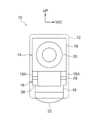
- FIG. 1 shows a side view of the imaging device 10 according to the first embodiment of the present invention as seen from one side in the vehicle width direction
- FIG. 2 shows a front view of the imaging device 10 as seen from the rear of the vehicle. Is shown.
- the front side of the vehicle is indicated by an arrow FR
- one side in the vehicle width direction is indicated by an arrow WO
- the upper side is indicated by an arrow UP.
- the imaging device 10 according to the present embodiment is installed outside at the front end of the vehicle in the middle in the vertical direction of the side door (front side door, vehicle body side) of the vehicle.
- the imaging device 10 includes a substantially rectangular parallelepiped box-shaped storage case 12 as a storage body, and the storage case 12 is restricted from entering water.
- a main camera 14 (first image pickup means) and a sub camera 16 (second image pickup means) as image pickup means are housed in the storage case 12, and the main camera 14 and sub camera 16 are stored in the storage case 12. It is fixed.
- the main camera 14 is disposed on the vehicle rear side and the upper side of the sub camera 16, and the main camera 14 and the sub camera 16 have their front ends directed toward the rear and the lower side of the vehicle, respectively.
- the main camera 14 and the sub camera 16 are provided with a holder 18 as a holding unit.
- the main camera 14 and the sub camera 16 have a main lens 20 (first lens) as a lens unit at the front end side of the holder 18, respectively. 1 lens portion) and a sub lens 22 (second lens portion) are provided.
- the optical axes (center axes) of the main lens 20 and the sub lens 22 are directed toward the rear and the lower side of the vehicle, respectively, and the optical axes of the main lens 20 and the sub lens 22 are arranged on the same plane perpendicular to the vehicle width direction.
- the surfaces of the main lens 20 and the sub lens 22 are exposed to the outside of the housing case 12, and the main lens 20 and the sub lens 22 and the peripheral wall of the housing case 12 are respectively sealed to enter the housing case 12. Ingress of water is limited.
- the main camera 14 and the sub camera 16 have a flat main sensor substrate 24 (first operation means, see FIGS. 4A and 4B) and a sub sensor substrate 26 (first operation means) as operation means on the proximal end side of the holder 18, respectively. 2 actuating means), and the main sensor substrate 24 and the sub sensor substrate 26 are disposed perpendicular to the optical axes of the main lens 20 and the sub lens 22, respectively.
- Image sensors 28 are provided on the surfaces of the main sensor substrate 24 and the sub sensor substrate 26, respectively, and a first connector constituting second connection means is provided on the back surface of the sub sensor substrate 26.
- a sensor connector 30 is provided.
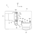
- a predetermined number (for example, two) of columnar mounting portions 18A are provided at the base end portions of the main camera 14 and the sub camera 16, and the mounting portions 18A are respectively provided from the holder 18 through the main sensor substrate 24 and the sub sensor substrate 26. It protrudes to the base end side.
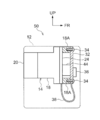
- a flat control board 32 (see FIGS. 4A and 4B) as a control means is attached to the attachment portion 18A of the sub camera 16 by fastening with a screw 34.
- the control board 32 is an optical axis of the sub lens 22. Is arranged vertically.
- the control board 32 can be detached from the attachment part 18A of the sub camera 16 by releasing the fastening with the screw 34, and the control board 32 can be attached to the attachment part 18A of the main camera 14 by fastening with the screw 34. (See FIG. 3).
- a control connector 36 as a second connector constituting the second connecting means is provided, and the control connector 36 is connected to the sensor connector 30 of the sub sensor board 26.
- the control board 32 is electrically connected to the sub sensor board 26 via the control connector 36 and the sensor connector 30.
- the control board 32 is removed from the mounting portion 18A of the sub camera 16, the control board 36 and The connection with the sensor connector 30 is released, and the electrical connection between the control board 32 and the sub sensor board 26 is released.
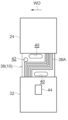
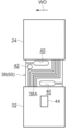
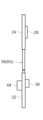
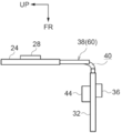
- the control board 32 and the main sensor board 24 of the main camera 14 are connected by a strip-like flexible board 38 (see FIGS. 4A and 4B) as a connection means (first connection means). It extends between the substrate 32 and the main sensor substrate 24.
- the flexible board 38 is provided with a predetermined number of wirings 38A.
- the flexible board 38 electrically connects the control board 32 and the main sensor board 24 by the wiring 38A, and the control board 32 and the main sensor board 24. The electrical connection with is disabled.
- the flexible substrate 38 is flexible and can be bent and bent, and the flexible substrate 38 is curved in the extending direction (see FIGS. 5A and 5B).
- One side portion in the longitudinal direction (control board 32 side portion) of the wiring 38A is extended in the extending direction of the flexible substrate 38 at one end portion in the extending width direction (one side end portion in the vehicle width direction) of the flexible substrate 38.
- the other side portion in the longitudinal direction (the main sensor substrate 24 side portion) is extended in the extending direction of the flexible substrate 38 at the other end portion in the extending width direction (the other end portion in the vehicle width direction) of the flexible substrate 38.
- the intermediate portion in the longitudinal direction of the wiring 38 ⁇ / b> A extends in the extending width direction (vehicle width direction) of the flexible substrate 38.
- a long, substantially elliptical cutout 40 as a cutting portion is formed through the flexible substrate 38 at the end on the control substrate 32 side and the end on the main sensor substrate 24 side.
- the notch 40 on the control board 32 side and the notch 40 on the main sensor board 24 side are each extended from the center in the extending width direction of the flexible substrate 38 to the other side in the extending width direction and one side in the extending width direction.
- the central portions of the cutout portions 40 in the extending direction of the flexible substrate 38 are opposed to each other in the extending direction of the flexible substrate 38.
- a circular fixing hole 42 as a fixing portion is formed through the flexible substrate 38 at the end on the main sensor substrate 24 side (or the end on the control substrate 32 side).
- the fixing hole 42 is formed in the flexible substrate 38. It is arrange
- a connector 44 is provided on the rear surface of the control board 32, and the control board 32 is electrically connected to a control device (not shown) in the vehicle via the connector 44. Therefore, under the control of the control board 32, the main sensor board 24 is electrically operated, and the main camera 14 (the image sensor 28 of the main sensor board 24) takes an image of the rear side of the vehicle via the main lens 20. Further, under the control of the control board 32, the sub sensor board 26 is electrically operated, and the sub camera 16 (the image sensor 28 of the sub sensor board 26) images the lower side via the sub lens 22. Even when the electrical connection between the control board 32 and the sub sensor board 26 is released, the main sensor board 24 can be electrically operated by the control of the control board 32.
- a monitor (not shown) as a display means is electrically connected to the control device, and images captured by the main camera 14 and the sub camera 16 are displayed on the monitor under the control of the control device.
- the monitor is disposed in the passenger compartment, and the occupant of the vehicle visually confirms the rear side and the lower side of the vehicle by checking the images (images captured by the main camera 14 and the sub camera 16) displayed on the monitor. Is assisted.
- the control board 32 is attached to the attachment portion 18A of the main camera 14 by fastening with screws 34 (the control board 32 is temporarily attached to the main camera 14).
- the main camera 14 (including the control board 32 and the flexible board 38) is assembled in the housing case 12 and the sub camera 16 is assembled in the housing case 12 as long as it is fixed.
- the control board 32 is attached to the attachment part 18A of the sub camera 16 by fastening with screws 34, and the control connector 36 of the control board 32 and the sub sensor board 26 are attached.
- the sensor connector 30 is connected.
- control board 32 is attached to the sub camera 16 (attachment portion 18 ⁇ / b> A) by fastening with the screw 34, and the fastening by the screw 34 of the control board 32 to the sub camera 16 is released.
- the control board 32 is removed from the sub camera 16 and the electrical connection by the control connector 36 and the sensor connector 30 between the control board 32 and the sub sensor board 26 is released.
- the sub camera 16 can be easily separated from the main camera 14 and the control board 32, and the number of cameras (the main camera 14 and the sub camera 16) can be easily changed.
- the main camera 14, the control board 32, and the flexible board between the imaging apparatus 10 having the specification provided with the sub camera 16 and the imaging apparatus 50 having the specification not provided with the sub camera 16 (see FIG. 6). 38 can be shared and the cost can be reduced.
- control board 32 can be attached to the main camera 14 (attachment portion 18A) and the sub camera 16 (attachment portion 18A). Therefore, as described above, when the imaging device 10 is assembled, the main camera 14 to which the control board 32 is attached can be assembled in the housing case 12 and the sub camera 16 can be assembled in the housing case 12. . Thus, unlike the case where the sub camera 16 to which the control board 32 is attached is assembled in the housing case 12 and the main camera 14 is assembled in the housing case 12, the main board 14 can be assembled even if the extension direction dimension of the flexible board 38 is small. The camera 14 and the sub camera 16 can be easily assembled in the housing case 12, and the imaging device 10 can be easily assembled. In addition, the control board 32 can be attached to the main camera 14 in the imaging device 50 (see FIG. 6) having a specification in which the sub camera 16 is not provided.
- control board 32 controls the main camera 14 (main sensor board 24) and the sub camera 16 (sub sensor board 26). For this reason, it is not necessary to separately provide the control board 32 for the main camera 14 and the sub camera 16, the number of the control boards 32 can be reduced, the image pickup apparatus 10 can be downsized, and the cost can be reduced.
- the main camera 14 including the main sensor substrate 24
- the sub camera 16 including the sub sensor substrate 26
- the accommodating case 12 supplies water to the main sensor substrate 24 and the sub sensor substrate 26.
- Limit the intrusion For this reason, it is not necessary to separately provide the housing case 12 for the main camera 14 (including the main sensor board 24) and the sub camera 16 (including the sub sensor board 26), and the imaging apparatus 10 is particularly arranged in the vehicle front-rear direction. The size can be reduced and the cost can be reduced.
- control board 32 and the flexible board 38 are housed in the housing case 12, and the housing case 12 restricts the entry of water into the control board 32 and the flexible board 38. For this reason, it is possible to eliminate the necessity of separately providing the housing case 12 on the control board 32 and the flexible board 38, and it is possible to reduce the size of the imaging device 10 particularly in the vehicle front-rear direction and to reduce the cost.
- the flexible substrate 38 has flexibility. Therefore, as in the present embodiment, the flexible substrate 38 is curved in the extending direction in accordance with the relative positions of the main camera 14 (main sensor substrate 24) and the sub camera 16 (sub sensor substrate 26), whereby the imaging device 10 is In particular, the size can be reduced in the vehicle longitudinal direction and the vertical direction.
- FIG. 9A shows a plan view of the assembled state of the flexible board 38 and the like in the image pickup apparatus 60 according to the second embodiment of the present invention as seen from above, and FIG. The assembled state of the board 38 and the like is shown in a side view seen from the other side in the vehicle width direction.
- the imaging device 60 according to the present embodiment has substantially the same configuration as that of the first embodiment, but differs in the following points.
- the optical axis of the main lens 20 of the main camera 14 is directed in a direction toward one side in the vehicle width direction (for example, outward in the vehicle width direction) toward the rear of the vehicle.
- the sub-lens 22 are not arranged on the same plane.
- the surface of the main sensor board 24 is directed in the direction toward the vehicle width direction toward the rear of the vehicle, and the surface of the main sensor board 24 and the surface of the control board 32 are Are not arranged on the same plane.
- the end of the flexible board 38 on the control board 32 side and the other side in the extending width direction extends from the notch 40 on the control board 32 side to the extending width of the flexible board 38.
- the end of the flexible board 38 on the side of the main sensor board 24 and on the one side in the extending width direction extends from the notch 40 on the side of the main sensor board 24 to the flexible board 38. It is cut along the stretch width direction.
- the flexible substrate 38 has an extension width as shown in FIGS. 9A and 9B.
- the surface of the main sensor substrate 24 is directed in a direction toward the vehicle width direction as it goes rearward of the vehicle.
- the flexible substrate 38 is fixed in the housing case 12 by fixing screws (not shown) in the fixing holes 42 (see FIG. 7A).
- the flexible substrate 38 is bent along the extending direction at a portion between the pair of notches 40 at the center in the extending width direction. For this reason, even when the orientation of the surface of the main sensor substrate 24 and the surface of the control substrate 32 is not arranged on the same plane, the flexible substrate 38 can be prevented from being twisted and deformed around the stretching direction, and the flexible substrate 38 can be stretched. Input of a load around the direction can be suppressed.
- the flexible substrate 38 is fixed in the housing case 12 in the fixing hole 42 in the vicinity of the bent portion. For this reason, the flexible substrate 38 can be bent in a state where the flexible substrate 38 is fixed in the housing case 12 in the fixing hole 42. As a result, the flexible substrate 38 can be bent easily, and the position of the bent portion of the flexible substrate 38 and the accuracy of the extending direction can be improved.
- a cutout 40 is formed through the flexible substrate 38 at the end on the control substrate 32 side and the end on the main sensor substrate 24 side. For this reason, when cutting the end of the flexible substrate 38 on the control substrate 32 side and the other side in the extending width direction and the end portion on the main sensor substrate 24 side and one side in the extending width direction, the flexible substrate starts from the notch 40. 38 can be cut, and the flexible substrate 38 can be easily cut.
- the main camera 14, the sub camera 16, and the control board 32 are provided between the imaging device 10 of the first embodiment and the imaging device 60 of the present embodiment in which the direction of the optical axis of the main lens 20 of the main camera 14 is different.
- the flexible substrate 38 can be shared. For this reason, cost can be reduced.
- the imaging device 60 can be applied to a plurality of types of vehicles in which at least one of the position and orientation of the optical axis of the main lens 20 of the main camera 14 is different, and the types of vehicles to which the imaging device 60 can be applied can be increased.
- the flexible substrate 38 is bent between the pair of cutout portions 40.
- the flexible substrate 38 may be bent between the pair of cut portions or between the cut portion and the cutout portion 40.
- control board 32 is attached to the sub camera 16, and the control board 32 and the sub sensor board 26 are electrically connected by the control connector 36 and the sensor connector 30, and the control is performed.
- the substrate 32 and the main sensor substrate 24 were electrically connected by a flexible substrate 38.
- control board 32 is attached to the main camera 14, the control board 32 and the main sensor board 24 are electrically connected by the control connector 36 and the sensor connector 30, and the control board 32 and the sub sensor board 26 are connected to the flexible board 38. May be electrically connected.
- the flexible board 38 cannot release the electrical connection between the control board 32 and the main sensor board 24.
- the flexible board 38 may be capable of releasing the electrical connection between the control board 32 and the main sensor board 24.
- control board 32 and the main sensor board 24 are electrically connected by the flexible board 38.
- main sensor board 24 and the sub sensor board 26 may be electrically connected by the flexible board 38, and the control board 32 and the sub sensor board 26 may be electrically connected by the flexible board 38.
- the imaging devices 10 and 60 are provided with two cameras (the main camera 14 and the sub camera 16).
- the imaging devices 10 and 60 may be provided with three or more cameras (the main camera 14 and the sub camera 16).
- the number of control boards 32 may be smaller than the number of cameras.
- the camera (the main camera 14 and the sub camera 16) can capture the rear side and the lower side of the vehicle.
- the camera may be able to image in other directions (for example, the front side, the upper side, the one side in the vehicle width direction, and the other side in the vehicle width direction).
- the imaging devices 10 and 60 are installed on the side door of the vehicle. However, you may install the imaging devices 10 and 60 in parts other than the side door of a vehicle.
- Imaging device 12 Housing case (housing body) 14 Main camera (imaging means) 16 Sub camera (imaging means) 24 Main sensor board (actuating means) 26 Sub sensor board (actuating means) 32 Control board (control means) 38 Flexible substrate (connecting means) 60 Imaging device
Landscapes
- Engineering & Computer Science (AREA)
- Multimedia (AREA)
- Signal Processing (AREA)
- Physics & Mathematics (AREA)
- General Physics & Mathematics (AREA)
- Mechanical Engineering (AREA)
- Studio Devices (AREA)
- Fittings On The Vehicle Exterior For Carrying Loads, And Devices For Holding Or Mounting Articles (AREA)
- Structure And Mechanism Of Cameras (AREA)
Abstract
撮像装置では、メインカメラが制御基板にフレキシブル基板によって接続されると共に、サブカメラが制御基板にセンサコネクタ及び制御コネクタによって接続されている。ここで、サブカメラに制御基板がネジによる締結によって取付けられており、サブカメラへの制御基板のネジによる締結が解除されることで、サブカメラから制御基板が取外される。このため、カメラの数を容易に変更できる。
Description
本発明は、車両に設けられる複数の撮像手段を備えた撮像装置に関する。
特開2014-231334号公報に記載の車両用サイドカメラ装置では、ブラケット部材とカバー部材との間にカメラが収容されている。
ここで、この車両用サイドカメラ装置において、仮に、一対のカメラが設けられると共に、一方のカメラの制御基板が他方のカメラに設けられる場合でも、カメラの数を容易に変更できるのが好ましい。
本発明は、上記事実を考慮し、撮像手段の数を容易に変更できる撮像装置を得ることが目的である。
本発明の第1態様の撮像装置は、車両に設けられ、撮像可能にされる複数の撮像手段と、前記撮像手段に取付けられ、前記撮像手段に電気的に接続されて前記撮像手段を制御すると共に、前記撮像手段から取外し可能にされる制御手段と、を備えている。
本発明の第2態様の撮像装置は、本発明の第1態様の撮像装置において、前記制御手段を複数の前記撮像手段に取付け可能にされる。
本発明の第3態様の撮像装置は、本発明の第1態様又は第2態様の撮像装置において、前記制御手段が複数の前記撮像手段を制御する。
本発明の第4態様の撮像装置は、本発明の第1態様~第3態様の何れか1つの撮像装置において、複数の前記撮像手段のそれぞれに設けられ、電気的に作動されて前記撮像手段が撮像する作動手段と、複数の前記作動手段が収容され、複数の前記作動手段への水の浸入を制限する収容体と、を備えている。
本発明の第5態様の撮像装置は、本発明の第1態様~第4態様の何れか1つの撮像装置において、可撓性を有し、複数の前記撮像手段を電気的に接続する接続手段を備えている。
本発明の第1態様の撮像装置では、車両に複数の撮像手段が設けられており、撮像手段は撮像可能にされている。さらに、撮像手段に制御手段が取付けられており、制御手段は、撮像手段に電気的に接続されて、撮像手段を制御する。
ここで、制御手段が撮像手段から取外し可能にされている。このため、撮像手段の数を容易に変更できる。
本発明の第2態様の撮像装置では、制御手段を複数の撮像手段に取付け可能にされている。このため、撮像手段から取外された制御手段を当該撮像手段以外の撮像手段に取付けることができる。
本発明の第3態様の撮像装置では、制御手段が複数の撮像手段を制御する。このため、制御手段の数を少なくできる。
本発明の第4態様の撮像装置では、複数の撮像手段のそれぞれに作動手段が設けられており、作動手段が電気的に作動されて、撮像手段が撮像する。
ここで、複数の作動手段が収容体に収容されており、収容体が複数の作動手段への水の浸入を制限する。このため、作動手段毎に収容体を設ける必要をなくすことができる。
本発明の第5態様の撮像装置では、複数の撮像手段を接続手段が電気的に接続している。
ここで、接続手段が可撓性を有している。このため、複数の撮像手段の相対位置により接続手段に負荷が入力される場合でも、接続手段が損傷することを抑制できる。
[第1実施形態]
図1には、本発明の第1実施形態に係る撮像装置10が車幅方向一方から見た側面図にて示されており、図2には、撮像装置10が車両後方から見た正面図にて示されている。なお、図面では、車両前方を矢印FRで示し、車幅方向一方を矢印WOで示し、上方を矢印UPで示している。
図1には、本発明の第1実施形態に係る撮像装置10が車幅方向一方から見た側面図にて示されており、図2には、撮像装置10が車両後方から見た正面図にて示されている。なお、図面では、車両前方を矢印FRで示し、車幅方向一方を矢印WOで示し、上方を矢印UPで示している。
本実施形態に係る撮像装置10は、車両のサイドドア(フロントサイドドア、車体側)の上下方向中間部の車両前側端に外側において設置されている。
図1及び図2に示す如く、撮像装置10は、収容体としての略直方体形箱状の収容ケース12を備えており、収容ケース12は、内部への水の浸入が制限されている。
収容ケース12内には、撮像手段としてのメインカメラ14(第1撮像手段)及びサブカメラ16(第2撮像手段)が収容されており、メインカメラ14及びサブカメラ16は、収容ケース12内に固定されている。メインカメラ14は、サブカメラ16の車両後側かつ上側に配置されており、メインカメラ14及びサブカメラ16は、それぞれ先端側を車両後方及び下方に向けられている。
メインカメラ14及びサブカメラ16には、保持部としてのホルダ18が設けられており、メインカメラ14及びサブカメラ16には、それぞれ、ホルダ18の先端側において、レンズ部としてのメインレンズ20(第1レンズ部)及びサブレンズ22(第2レンズ部)が設けられている。メインレンズ20及びサブレンズ22の光軸(中心軸線)は、それぞれ車両後方及び下方に向けられており、メインレンズ20及びサブレンズ22の光軸は、車幅方向に垂直な同一平面上に配置されている。メインレンズ20及びサブレンズ22の表面は、収容ケース12外に露出されており、メインレンズ20及びサブレンズ22と収容ケース12の周壁との間は、それぞれ、シールされて、収容ケース12内への水の浸入が制限されている。
メインカメラ14及びサブカメラ16には、それぞれ、ホルダ18の基端側において、作動手段としての平板状のメインセンサ基板24(第1作動手段、図4A及び図4B参照)及びサブセンサ基板26(第2作動手段)が設けられており、メインセンサ基板24及びサブセンサ基板26は、それぞれメインレンズ20及びサブレンズ22の光軸に垂直に配置されている。メインセンサ基板24及びサブセンサ基板26の表面には、それぞれ、撮像素子28(イメージセンサ、図4B参照)が設けられており、サブセンサ基板26の裏面には、第2接続手段を構成する第1コネクタとしてのセンサコネクタ30が設けられている。
メインカメラ14及びサブカメラ16の基端部には、柱状の取付部18Aが所定数(例えば2個)設けられており、取付部18Aは、それぞれホルダ18からメインセンサ基板24及びサブセンサ基板26より基端側に突出されている。
サブカメラ16の取付部18Aには、制御手段としての平板状の制御基板32(図4A及び図4B参照)がネジ34による締結によって取付けられており、制御基板32は、サブレンズ22の光軸に垂直に配置されている。制御基板32は、ネジ34による締結の解除によって、サブカメラ16の取付部18Aから取外し可能にされており、制御基板32は、メインカメラ14の取付部18Aにネジ34による締結によって取付け可能にされている(図3参照)。制御基板32の表面には、第2接続手段を構成する第2コネクタとしての制御コネクタ36が設けられており、制御コネクタ36は、サブセンサ基板26のセンサコネクタ30と接続されている。制御基板32は、制御コネクタ36及びセンサコネクタ30を介してサブセンサ基板26と電気的に接続されており、制御基板32がサブカメラ16の取付部18Aから取外されることで、制御コネクタ36とセンサコネクタ30との接続が解除されて、制御基板32とサブセンサ基板26との電気的な接続が解除される。
制御基板32とメインカメラ14のメインセンサ基板24とは、接続手段(第1接続手段)としての帯状のフレキシブル基板38(図4A及び図4B参照)によって接続されており、フレキシブル基板38は、制御基板32とメインセンサ基板24との間で延伸されている。フレキシブル基板38には、所定数の配線38Aが設けられており、フレキシブル基板38は、配線38Aによって制御基板32とメインセンサ基板24とを電気的に接続すると共に、制御基板32とメインセンサ基板24との電気的な接続を解除不能にしている。フレキシブル基板38は、可撓性を有して、湾曲及び屈曲が可能にされており、フレキシブル基板38は、延伸方向において湾曲されている(図5A及び図5B参照)。
配線38Aの長手方向一側部(制御基板32側部分)は、フレキシブル基板38の延伸幅方向一端部(車幅方向一側端部)においてフレキシブル基板38の延伸方向に延伸されており、配線38Aの長手方向他側部(メインセンサ基板24側部分)は、フレキシブル基板38の延伸幅方向他端部(車幅方向他側端部)においてフレキシブル基板38の延伸方向に延伸されている。さらに、配線38Aの長手方向中間部は、フレキシブル基板38の延伸幅方向(車幅方向)に延伸されている。
フレキシブル基板38の制御基板32側端部及びメインセンサ基板24側端部には、切断部としての長尺略楕円状の切欠部40が貫通形成されている。制御基板32側の切欠部40及びメインセンサ基板24側の切欠部40は、それぞれフレキシブル基板38の延伸幅方向中央部から延伸幅方向他側及び延伸幅方向一側に延伸されており、一対の切欠部40のフレキシブル基板38延伸幅方向中央側部分は、互いにフレキシブル基板38の延伸方向において対向されている。
フレキシブル基板38には、メインセンサ基板24側端部(制御基板32側端部でもよい)において、固定部としての円状の固定孔42が貫通形成されており、固定孔42は、フレキシブル基板38の延伸幅方向中央部以外の部分に配置されている。
制御基板32の裏面には、コネクタ44が設けられており、制御基板32は、コネクタ44を介して車両内の制御装置(図示省略)に電気的に接続されている。このため、制御基板32の制御により、メインセンサ基板24が電気的に作動されて、メインカメラ14(メインセンサ基板24の撮像素子28)がメインレンズ20を介して車両後側を撮像する。さらに、制御基板32の制御により、サブセンサ基板26が電気的に作動されて、サブカメラ16(サブセンサ基板26の撮像素子28)がサブレンズ22を介して下側を撮像する。また、制御基板32とサブセンサ基板26との電気的な接続が解除された際でも、制御基板32の制御により、メインセンサ基板24が電気的に作動可能にされている。
制御装置には、表示手段としてのモニタ(図示省略)が電気的に接続されており、モニタには、制御装置の制御により、メインカメラ14及びサブカメラ16が撮像した像が表示される。モニタは、車室内に配置されており、車両の乗員がモニタに表示される像(メインカメラ14及びサブカメラ16が撮像した像)を確認することで、乗員の車両後側及び下側の視認が補助される。
次に、本実施形態の作用を説明する。
以上の構成の撮像装置10を組付ける際には、図3に示す如く、メインカメラ14の取付部18Aに制御基板32をネジ34による締結によって取付けた状態(メインカメラ14に制御基板32を仮固定した状態であればよい)でメインカメラ14(制御基板32及びフレキシブル基板38を含む)を収容ケース12内に組付けると共に、サブカメラ16を収容ケース12内に組付ける。次に、メインカメラ14の取付部18Aから制御基板32を取外した後、サブカメラ16の取付部18Aに制御基板32をネジ34による締結によって取付けると共に、制御基板32の制御コネクタ36とサブセンサ基板26のセンサコネクタ30とを接続する。
ここで、撮像装置10では、サブカメラ16(取付部18A)に制御基板32がネジ34による締結によって取付けられており、サブカメラ16への制御基板32のネジ34による締結が解除されることで、サブカメラ16から制御基板32が取外されると共に、制御基板32とサブセンサ基板26との制御コネクタ36及びセンサコネクタ30による電気的な接続が解除される。
このため、メインカメラ14及び制御基板32からサブカメラ16を容易に分離でき、カメラ(メインカメラ14及びサブカメラ16)の数を容易に変更できる。これにより、サブカメラ16が設けられている仕様の撮像装置10とサブカメラ16が設けられていない仕様の撮像装置50(図6参照)との間で、メインカメラ14、制御基板32及びフレキシブル基板38を共用でき、コストを低減できる。
また、メインカメラ14(取付部18A)及びサブカメラ16(取付部18A)に制御基板32を取付け可能にされている。このため、上述の如く、撮像装置10を組付ける際には、制御基板32を取付けたメインカメラ14を収容ケース12内に組付けると共に、サブカメラ16を収容ケース12内に組付けることができる。これにより、制御基板32を取付けたサブカメラ16を収容ケース12内に組付けると共にメインカメラ14を収容ケース12内に組付ける場合とは異なり、フレキシブル基板38の延伸方向寸法が小さくても、メインカメラ14及びサブカメラ16を収容ケース12内に容易に組付けることができ、撮像装置10を容易に組付けることができる。しかも、サブカメラ16が設けられていない仕様の撮像装置50(図6参照)において、メインカメラ14に制御基板32を取付けることができる。
さらに、制御基板32がメインカメラ14(メインセンサ基板24)及びサブカメラ16(サブセンサ基板26)を制御する。このため、メインカメラ14とサブカメラ16とに別々に制御基板32を設ける必要をなくすことができ、制御基板32の数を少なくできて、撮像装置10を小型化できると共に、コストを低減できる。
また、メインカメラ14(メインセンサ基板24を含む)及びサブカメラ16(サブセンサ基板26を含む)が収容ケース12内に収容されており、収容ケース12がメインセンサ基板24及びサブセンサ基板26への水の浸入を制限する。このため、メインカメラ14(メインセンサ基板24を含む)とサブカメラ16(サブセンサ基板26を含む)とに別々に収容ケース12を設ける必要をなくすことができ、撮像装置10を特に車両前後方向において小型化できると共に、コストを低減できる。
さらに、制御基板32及びフレキシブル基板38が収容ケース12内に収容されており、収容ケース12が制御基板32及びフレキシブル基板38への水の浸入を制限する。このため、制御基板32及びフレキシブル基板38に収容ケース12を別途設ける必要をなくすことができ、撮像装置10を特に車両前後方向において小型化できると共に、コストを低減できる。
また、フレキシブル基板38が可撓性を有している。このため、本実施形態の如く、メインカメラ14(メインセンサ基板24)とサブカメラ16(サブセンサ基板26)との相対位置に伴い、フレキシブル基板38を延伸方向において湾曲させることで、撮像装置10を特に車両前後方向及び上下方向において小型化できる。
[第2実施形態]
図9Aには、本発明の第2実施形態に係る撮像装置60におけるフレキシブル基板38等の組付状態が上方から見た平面図にて示されており、図9Bには、撮像装置60におけるフレキシブル基板38等の組付状態が車幅方向他方から見た側面図にて示されている。
図9Aには、本発明の第2実施形態に係る撮像装置60におけるフレキシブル基板38等の組付状態が上方から見た平面図にて示されており、図9Bには、撮像装置60におけるフレキシブル基板38等の組付状態が車幅方向他方から見た側面図にて示されている。
本実施形態に係る撮像装置60は、上記第1実施形態と、ほぼ同様の構成であるが、以下の点で異なる。
本実施形態に係る撮像装置60では、メインカメラ14のメインレンズ20の光軸が車両後方へ向かうに従い車幅方向一方(例えば車幅方向外方)へ向かう方向に向けられており、メインレンズ20とサブレンズ22との光軸は、同一平面上に配置されていない。このため、図9A及び図9Bに示す如く、メインセンサ基板24の表面が車両後方へ向かうに従い車幅方向一方へ向かう方向に向けられており、メインセンサ基板24の表面と制御基板32の表面との向きは、同一平面上に配置されない。
図7A及び図7Bに示す如く、フレキシブル基板38の制御基板32側かつ延伸幅方向他側(車幅方向他側)の端部は、制御基板32側の切欠部40からフレキシブル基板38の延伸幅方向に沿って切断されており、フレキシブル基板38のメインセンサ基板24側かつ延伸幅方向一側(車幅方向一側)の端部は、メインセンサ基板24側の切欠部40からフレキシブル基板38の延伸幅方向に沿って切断されている。
このため、図8A及び図8Bに示す如く、フレキシブル基板38の制御基板32側端部がフレキシブル基板38の延伸方向において湾曲された後に、図9A及び図9Bに示す如く、フレキシブル基板38が延伸幅方向中央部の一対の切欠部40間の部分において延伸方向に沿って屈曲されることで、メインセンサ基板24の表面が車両後方へ向かうに従い車幅方向一方へ向かう方向に向けられている。
フレキシブル基板38は、固定孔42(図7A参照)において、固定ネジ(図示省略)によって収容ケース12内に固定されている。
ここで、本実施形態でも、上記第1実施形態と同様の作用及び効果を奏することができる。
さらに、フレキシブル基板38が延伸幅方向中央部の一対の切欠部40間の部分において延伸方向に沿って屈曲されている。このため、メインセンサ基板24の表面と制御基板32の表面との向きが同一平面上に配置されない場合でも、フレキシブル基板38が延伸方向周りに捩れ変形されることを抑制でき、フレキシブル基板38に延伸方向周りへの負荷が入力されることを抑制できる。
また、フレキシブル基板38が屈曲部分の近傍の固定孔42において収容ケース12内に固定されている。このため、フレキシブル基板38が固定孔42において収容ケース12内に固定された状態で、フレキシブル基板38を屈曲させることができる。これにより、フレキシブル基板38を容易に屈曲させることができると共に、フレキシブル基板38の屈曲部分の位置及び延伸方向の正確性を高めることができる。
さらに、フレキシブル基板38の制御基板32側端部及びメインセンサ基板24側端部に切欠部40が貫通形成されている。このため、フレキシブル基板38の制御基板32側かつ延伸幅方向他側の端部及びメインセンサ基板24側かつ延伸幅方向一側の端部を切断する際には、切欠部40を起点としてフレキシブル基板38を切断でき、フレキシブル基板38を容易に切断できる。
また、メインカメラ14のメインレンズ20の光軸の向きが異なる上記第1実施形態の撮像装置10と本実施形態の撮像装置60との間で、メインカメラ14、サブカメラ16及び制御基板32のみならず、フレキシブル基板38も共用できる。このため、コストを低減できる。
さらに、フレキシブル基板38の屈曲部分の位置、延伸方向及び屈曲角度の少なくとも1つを変更することで、メインセンサ基板24の表面の位置及び向きの少なくとも一方を変更できて、メインカメラ14のメインレンズ20の光軸の位置及び向きの少なくとも一方を変更できる。このため、メインカメラ14のメインレンズ20の光軸の位置及び向きの少なくとも一方が異なる複数種類の車両に撮像装置60を適用でき、撮像装置60を適用できる車両の種類を多くできる。
なお、本実施形態では、フレキシブル基板38を一対の切欠部40間で屈曲させた。しかしながら、フレキシブル基板38を一対の切断部分間又は切断部分と切欠部40との間で屈曲させてもよい。
また、上記第1実施形態及び第2実施形態では、サブカメラ16に制御基板32を取付けて、制御基板32とサブセンサ基板26とを制御コネクタ36及びセンサコネクタ30によって電気的に接続すると共に、制御基板32とメインセンサ基板24とをフレキシブル基板38によって電気的に接続した。しかしながら、メインカメラ14に制御基板32を取付けて、制御基板32とメインセンサ基板24とを制御コネクタ36及びセンサコネクタ30によって電気的に接続すると共に、制御基板32とサブセンサ基板26とをフレキシブル基板38によって電気的に接続してもよい。
さらに、上記第1実施形態及び第2実施形態では、フレキシブル基板38が制御基板32とメインセンサ基板24との電気的な接続を解除不能にした。しかしながら、フレキシブル基板38が制御基板32とメインセンサ基板24との電気的な接続を解除可能にしてもよい。
また、上記第1実施形態及び第2実施形態では、フレキシブル基板38によって制御基板32とメインセンサ基板24とを電気的に接続した。しかしながら、フレキシブル基板38によってメインセンサ基板24とサブセンサ基板26とを電気的に接続してもよく、また、フレキシブル基板38によって制御基板32とサブセンサ基板26とを電気的に接続してもよい。
さらに、上記第1実施形態及び第2実施形態では、撮像装置10、60に2個のカメラ(メインカメラ14及びサブカメラ16)を設けた。しかしながら、撮像装置10、60に3個以上のカメラ(メインカメラ14及びサブカメラ16)を設けてもよい。この場合、制御基板32の数をカメラの数よりも少なくしてもよい。
また、上記第1実施形態及び第2実施形態では、カメラ(メインカメラ14及びサブカメラ16)が車両後側と下側とを撮像可能にした。しかしながら、カメラが他の方向(例えば車両前側、上側、車幅方向一側及び車幅方向他側)を撮像可能にしてもよい。
さらに、上記第1実施形態及び第2実施形態では、撮像装置10、60を車両のサイドドアに設置した。しかしながら、撮像装置10、60を車両のサイドドア以外の部分に設置してもよい。
2016年3月7日に出願された日本国特許出願2016-43502号の開示は、その全体が参照により本明細書に取込まれる。
10 撮像装置
12 収容ケース(収容体)
14 メインカメラ(撮像手段)
16 サブカメラ(撮像手段)
24 メインセンサ基板(作動手段)
26 サブセンサ基板(作動手段)
32 制御基板(制御手段)
38 フレキシブル基板(接続手段)
60 撮像装置
12 収容ケース(収容体)
14 メインカメラ(撮像手段)
16 サブカメラ(撮像手段)
24 メインセンサ基板(作動手段)
26 サブセンサ基板(作動手段)
32 制御基板(制御手段)
38 フレキシブル基板(接続手段)
60 撮像装置
Claims (8)
- 車両に設けられ、撮像可能にされる複数の撮像手段と、
前記撮像手段に取付けられ、前記撮像手段に電気的に接続されて前記撮像手段を制御すると共に、前記撮像手段から取外し可能にされる制御手段と、
を備えた撮像装置。 - 前記制御手段を複数の前記撮像手段に取付け可能にされる請求項1記載の撮像装置。
- 前記制御手段が複数の前記撮像手段を制御する請求項1又は請求項2記載の撮像装置。
- 複数の前記撮像手段のそれぞれに設けられ、電気的に作動されて前記撮像手段が撮像する作動手段と、
複数の前記作動手段が収容され、複数の前記作動手段への水の浸入を制限する収容体と、
を備えた請求項1~請求項3の何れか1項記載の撮像装置。 - 可撓性を有し、複数の前記撮像手段を電気的に接続する接続手段を備えた請求項1~請求項4の何れか1項記載の撮像装置。
- 切欠部が設けられ、複数の前記撮像手段を電気的に接続する接続手段を備えた請求項1~請求項5の何れか1項記載の撮像装置。
- 切断部が設けられ、複数の前記撮像手段を電気的に接続する接続手段を備えた請求項1~請求項6の何れか1項記載の撮像装置。
- 屈曲可能にされ、複数の前記撮像手段を電気的に接続する接続手段を備えた請求項1~請求項7の何れか1項記載の撮像装置。
Priority Applications (1)
| Application Number | Priority Date | Filing Date | Title |
|---|---|---|---|
| US16/080,842 US20190058835A1 (en) | 2016-03-07 | 2017-03-02 | Imaging device |
Applications Claiming Priority (2)
| Application Number | Priority Date | Filing Date | Title |
|---|---|---|---|
| JP2016043502A JP2017159694A (ja) | 2016-03-07 | 2016-03-07 | 撮像装置 |
| JP2016-043502 | 2016-03-07 |
Publications (1)
| Publication Number | Publication Date |
|---|---|
| WO2017154745A1 true WO2017154745A1 (ja) | 2017-09-14 |
Family
ID=59789429
Family Applications (1)
| Application Number | Title | Priority Date | Filing Date |
|---|---|---|---|
| PCT/JP2017/008367 Ceased WO2017154745A1 (ja) | 2016-03-07 | 2017-03-02 | 撮像装置 |
Country Status (3)
| Country | Link |
|---|---|
| US (1) | US20190058835A1 (ja) |
| JP (1) | JP2017159694A (ja) |
| WO (1) | WO2017154745A1 (ja) |
Cited By (1)
| Publication number | Priority date | Publication date | Assignee | Title |
|---|---|---|---|---|
| CN112970241A (zh) * | 2018-11-15 | 2021-06-15 | 索尼半导体解决方案公司 | 车载相机 |
Families Citing this family (1)
| Publication number | Priority date | Publication date | Assignee | Title |
|---|---|---|---|---|
| JP6719941B2 (ja) * | 2016-03-27 | 2020-07-08 | 日本電産コパル株式会社 | 電子部品搭載部材、及び撮像装置 |
Citations (4)
| Publication number | Priority date | Publication date | Assignee | Title |
|---|---|---|---|---|
| JPH07186831A (ja) * | 1993-12-28 | 1995-07-25 | Mitsubishi Electric Corp | 自動車の後側方監視装置 |
| JP2003327048A (ja) * | 2002-05-14 | 2003-11-19 | Murakami Corp | カメラ内蔵型バックミラー装置 |
| JP2008244560A (ja) * | 2007-03-26 | 2008-10-09 | Fujifilm Corp | 撮影システム |
| JP2009128521A (ja) * | 2007-11-21 | 2009-06-11 | Fujifilm Corp | フレキシブル配線板及び撮像装置 |
Family Cites Families (3)
| Publication number | Priority date | Publication date | Assignee | Title |
|---|---|---|---|---|
| JP2009017234A (ja) * | 2007-07-04 | 2009-01-22 | Sharp Corp | カメラ装置 |
| US9619718B2 (en) * | 2013-12-18 | 2017-04-11 | Johnson Controls Technology Company | In-vehicle camera and alert systems |
| CN106662793B (zh) * | 2015-05-27 | 2019-06-11 | 高途乐公司 | 使用稳定用常平架的常平架系统 |
-
2016
- 2016-03-07 JP JP2016043502A patent/JP2017159694A/ja active Pending
-
2017
- 2017-03-02 WO PCT/JP2017/008367 patent/WO2017154745A1/ja not_active Ceased
- 2017-03-02 US US16/080,842 patent/US20190058835A1/en not_active Abandoned
Patent Citations (4)
| Publication number | Priority date | Publication date | Assignee | Title |
|---|---|---|---|---|
| JPH07186831A (ja) * | 1993-12-28 | 1995-07-25 | Mitsubishi Electric Corp | 自動車の後側方監視装置 |
| JP2003327048A (ja) * | 2002-05-14 | 2003-11-19 | Murakami Corp | カメラ内蔵型バックミラー装置 |
| JP2008244560A (ja) * | 2007-03-26 | 2008-10-09 | Fujifilm Corp | 撮影システム |
| JP2009128521A (ja) * | 2007-11-21 | 2009-06-11 | Fujifilm Corp | フレキシブル配線板及び撮像装置 |
Cited By (4)
| Publication number | Priority date | Publication date | Assignee | Title |
|---|---|---|---|---|
| CN112970241A (zh) * | 2018-11-15 | 2021-06-15 | 索尼半导体解决方案公司 | 车载相机 |
| CN112970241B (zh) * | 2018-11-15 | 2024-03-01 | 索尼半导体解决方案公司 | 车载相机 |
| US11987184B2 (en) | 2018-11-15 | 2024-05-21 | Sony Semiconductor Solutions Corporation | Vehicle-mounted camera |
| US12545193B2 (en) | 2018-11-15 | 2026-02-10 | Sony Semiconductor Solutions Corporation | Vehicle-mounted camera |
Also Published As
| Publication number | Publication date |
|---|---|
| US20190058835A1 (en) | 2019-02-21 |
| JP2017159694A (ja) | 2017-09-14 |
Similar Documents
| Publication | Publication Date | Title |
|---|---|---|
| CN109644576B (zh) | 电子设备、相机设备和屏蔽机架 | |
| CN107153316B (zh) | 相机装置和相机模块 | |
| JP4679864B2 (ja) | ステレオカメラ、およびステレオカメラ用ステー | |
| JP2019099046A (ja) | センサー搭載構造 | |
| WO2016180875A1 (en) | Method for manufacturing a camera for a motor vehicle comprising electrical connecting of a circuit board and a lens housing, camera, driver assistance system as well as motor vehicle | |
| JP4109908B2 (ja) | 車両用ミラー装置 | |
| JP7085013B2 (ja) | 観察ユニットおよび内視鏡 | |
| US20180147999A1 (en) | Video-camera device for a motor vehicle and assembly method | |
| WO2017154745A1 (ja) | 撮像装置 | |
| JPWO2016170911A1 (ja) | 撮像装置 | |
| JP6220754B2 (ja) | 車載用カメラ | |
| US20140104427A1 (en) | Vehicle-mounted camera | |
| JP7122561B2 (ja) | 車載用アクセサリ装置、車載表示システム | |
| JP2015501585A (ja) | 自動車用の光学的手段 | |
| WO2016103928A1 (ja) | 撮像装置 | |
| WO2020137022A1 (ja) | 車載機器 | |
| JP6719941B2 (ja) | 電子部品搭載部材、及び撮像装置 | |
| JP2017163207A (ja) | 撮像装置 | |
| JP7095850B2 (ja) | ケーブル配索構造及びケーブル配索方法 | |
| JP7646102B2 (ja) | カメラユニット | |
| KR20090022911A (ko) | 자동차 후방 감시 시스템 | |
| EP3335413B1 (en) | Camera for a motor vehicle with an electronic unit arranged on the lens housing and motor vehicle | |
| WO2013105515A1 (ja) | レンズ鏡筒 | |
| JP6205495B2 (ja) | 接続ユニット用に改善したベアリングを備えた電子装置、自動車用カメラシステム、および自動車 | |
| JP2011228769A (ja) | ビデオカメラ装置及びそのカメラアダプタ構造 |
Legal Events
| Date | Code | Title | Description |
|---|---|---|---|
| NENP | Non-entry into the national phase |
Ref country code: DE |
|
| 121 | Ep: the epo has been informed by wipo that ep was designated in this application |
Ref document number: 17763085 Country of ref document: EP Kind code of ref document: A1 |
|
| 122 | Ep: pct application non-entry in european phase |
Ref document number: 17763085 Country of ref document: EP Kind code of ref document: A1 |