WO2017154648A1 - 加熱用パッケージおよび包装体 - Google Patents
加熱用パッケージおよび包装体 Download PDFInfo
- Publication number
- WO2017154648A1 WO2017154648A1 PCT/JP2017/007602 JP2017007602W WO2017154648A1 WO 2017154648 A1 WO2017154648 A1 WO 2017154648A1 JP 2017007602 W JP2017007602 W JP 2017007602W WO 2017154648 A1 WO2017154648 A1 WO 2017154648A1
- Authority
- WO
- WIPO (PCT)
- Prior art keywords
- metal layer
- insulating layer
- metal
- package
- heated
- Prior art date
- Legal status (The legal status is an assumption and is not a legal conclusion. Google has not performed a legal analysis and makes no representation as to the accuracy of the status listed.)
- Ceased
Links
Images








Classifications
-
- A—HUMAN NECESSITIES
- A47—FURNITURE; DOMESTIC ARTICLES OR APPLIANCES; COFFEE MILLS; SPICE MILLS; SUCTION CLEANERS IN GENERAL
- A47J—KITCHEN EQUIPMENT; COFFEE MILLS; SPICE MILLS; APPARATUS FOR MAKING BEVERAGES
- A47J27/00—Cooking-vessels
-
- B—PERFORMING OPERATIONS; TRANSPORTING
- B65—CONVEYING; PACKING; STORING; HANDLING THIN OR FILAMENTARY MATERIAL
- B65D—CONTAINERS FOR STORAGE OR TRANSPORT OF ARTICLES OR MATERIALS, e.g. BAGS, BARRELS, BOTTLES, BOXES, CANS, CARTONS, CRATES, DRUMS, JARS, TANKS, HOPPERS, FORWARDING CONTAINERS; ACCESSORIES, CLOSURES, OR FITTINGS THEREFOR; PACKAGING ELEMENTS; PACKAGES
- B65D81/00—Containers, packaging elements, or packages, for contents presenting particular transport or storage problems, or adapted to be used for non-packaging purposes after removal of contents
- B65D81/34—Containers, packaging elements, or packages, for contents presenting particular transport or storage problems, or adapted to be used for non-packaging purposes after removal of contents for packaging foodstuffs or other articles intended to be cooked or heated within the package
-
- H—ELECTRICITY
- H05—ELECTRIC TECHNIQUES NOT OTHERWISE PROVIDED FOR
- H05B—ELECTRIC HEATING; ELECTRIC LIGHT SOURCES NOT OTHERWISE PROVIDED FOR; CIRCUIT ARRANGEMENTS FOR ELECTRIC LIGHT SOURCES, IN GENERAL
- H05B6/00—Heating by electric, magnetic or electromagnetic fields
- H05B6/46—Dielectric heating
- H05B6/54—Electrodes
Definitions
- the present invention relates to a heating package and a package that are arranged between a first electrode and a second electrode that are arranged to face each other and are heated by high-frequency dielectric heating.
- the high-frequency power absorbed per unit volume is determined by the dielectric constant, dielectric loss, electric field strength, etc. of the material to be heated. There will be a good part and a poorly exothermic part. Therefore, when dielectric heating is performed in accordance with the thawing of the poorly exothermic part of the material to be heated, the heat generating runaway occurs in the part having good exothermicity after a certain heating time has elapsed, resulting in uneven heating of the material to be heated. There was a problem.
- a plurality of temperature sensors in contact with the heated material are provided, and the lowest temperature detected by the temperature sensor and the highest temperature detected by the temperature sensor are provided. If the temperature difference opens more than a certain level, the output of the high-frequency oscillator is stopped for a certain period of time, and heating unevenness is suppressed using the heat conduction of the material to be heated.
- a method of thawing by combining dielectric heating and natural thawing by heat conduction by repeatedly turning on and off the output of the high-frequency oscillator until the temperature of the high part reaches the set temperature (see, for example, Patent Document 1). ).
- Patent Document 1 measures the temperature of a plurality of locations of the material to be heated, and repeats on / off of the output of the high-frequency oscillator by the temperature difference to defrost while keeping the temperature difference of the portion small. Therefore, there is a problem that it takes a long time to defrost.
- the present applicant as another measure for eliminating the occurrence of heating unevenness in the heated material described above, is a pair of metal layers that are electrically connected to each other at the leading end and the trailing end of the short cake that is the heated material. It was proposed that the material to be heated is dielectrically heated while shielding the electric field with these metal layers (see Patent Document 2). In this way, by adjusting the heating efficiency of the material to be heated by using electric field shielding by the metal layer, it is possible to avoid the occurrence of heat runaway at the front end portion and the rear end portion of the short cake having good heat generation, It can be heated stably.
- the present invention solves these problems, can heat the material to be heated in a short time while avoiding the occurrence of uneven heating, and improves the handling of the heating package.
- An object is to provide a heating package and a package.
- the heating package of the present invention is a heating package that is disposed between the first electrode and the second electrode that are opposed to each other and heated by high-frequency dielectric heating, and the heating package includes a material to be heated, A package that wraps the material to be heated, and the material to be heated includes a first facing surface disposed to face the first electrode, and a second facing surface disposed to face the second electrode. And the package includes a first metal layer disposed on the first facing surface, a second metal layer disposed on the second facing surface, the first metal layer, and the second metal layer. A conductive portion for conducting the metal layer, and the first metal layer is formed inside a first metal outer peripheral edge covering portion that covers an outer peripheral edge of the first facing surface, and an inner side of the first metal outer peripheral edge covering portion.
- the packaging body of the present invention is a packaging body that is disposed between the first electrode and the second electrode that are opposed to each other and wraps a material to be heated that is heated by high-frequency dielectric heating.
- a first metal layer disposed on a first opposed surface of the heated material disposed opposite to the first electrode; and a second opposed surface of the heated material disposed opposed to the second electrode.
- a second metal layer disposed; and a conductive portion that conducts the first metal layer and the second metal layer, wherein the first metal layer covers an outer peripheral edge of the first facing surface.
- the object is solved by having an outer peripheral edge covering portion and a first metal opening formed inside the first metal outer peripheral edge covering portion.
- the first metal layer disposed on the first facing surface of the heated material includes the first metal outer periphery covering portion that covers the outer periphery of the first facing surface;
- the first metal outer periphery covering portion shields the outer periphery of the material to be heated, which tends to concentrate an electric field, by having the first metal opening formed inside the first metal outer periphery covering portion.
- a part of the first metal layer and a part of the second metal layer are adjacent to each other with at least one of the first insulating layer or the second insulating layer interposed therebetween.
- the conductive portions are formed between the metal layers without bringing the metal layers into direct contact with each other, so that the degree of freedom in designing the package can be improved.
- the package is formed on both the first insulating layer formed on both the inner surface and the outer surface of the first metal layer, and on both the inner surface and the outer surface of the second metal layer.
- the metal layer can be prevented from coming into direct contact with the heated material, and the insulating layer can insulate the metal layer from the electrode. There is no need to provide an additional insulating member.
- the second insulating layer disposed on the second facing surface of the material to be heated is formed so as to cover the second facing surface entirely.
- a housing for housing the material to be heated at the time of distribution or storage, such as prevention, or the heating package can be placed on a desk or the like with the second facing surface side of the material to be heated facing down As a package, it can function.
- the first insulating layer formed on the first facing surface of the material to be heated has the first insulating layer opening formed inside the first insulating layer outer periphery covering portion. Since it is possible to visually recognize the heated material from the outside through the first metal opening of the first metal layer and the first insulating layer opening of the first insulating layer, the kind of the heated material And the status can be easily confirmed.
- the first insulating layer disposed on the first facing surface of the material to be heated is formed so as to cover the first facing surface entirely. The handling property of the heating package can be improved, for example, by preventing the heating package from being placed on a desk or the like with the first facing surface side of the material to be heated facing downward.
- the packaging body includes the cover member formed separately from the packaging member having the first metal layer and the second metal layer. Since the packaging function can also be shared by the cover member, the design flexibility of the packaging member can be improved, for example, by designing the packaging member in a form that can be easily removed from the heated material. it can.
- the packaging body includes a first insulating layer disposed on the first facing surface, a second insulating layer disposed on the second facing surface, and the two opposed materials to be heated. By having two side surface insulating layers arranged on one side surface, the package can be configured as a box having a fixed shape.
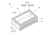
- Explanatory drawing which shows the usage condition of the package for a heating which concerns on 1st Embodiment.
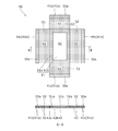
- the expanded view and sectional drawing which show the package of 1st Embodiment.
- the expanded view and sectional drawing which show the package of the 1st modification.
- the expanded view and sectional drawing which show the package of the 2nd modification.
- the perspective view which shows the package for a heating of 2nd Embodiment.
- the expanded view and sectional drawing which show the package body of 2nd Embodiment.
- the heating package 10 is disposed between the first electrode 60 and the second electrode 61 that are opposed to each other, and is heated by high-frequency dielectric heating.
- the package 30 is configured to wrap the material 20 to be heated.
- the first electrode 60 and the second electrode 61 are connected to a high frequency power source 62, and the heating package 10 is placed on the second electrode 61 with an insulating mount 70 interposed therebetween.
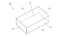
- the material to be heated 20 is a hexahedral frozen shortcake, and is opposed to the first opposed surface 21 disposed opposite to the first electrode 60 and the second electrode 61.
- the package 30 is formed by attaching metal layers 50 to 52 to the inner side surfaces of the insulating layers 41 to 45 made of an insulating sheet such as paper by vapor deposition, and synthesizing PP (polypropylene) or the like on the inner side surfaces of the metal layers 50 to 52. It is made of a laminate material on which insulating layers 41 to 45 made of resin are formed.
- the insulating layers 41 to 45 can be assembled in a box shape, and the first insulating layer 41 disposed outside the first opposing surface 21 and the second opposing surface 22.
- a second insulating layer 42 disposed outside the side surface, a side surface insulating layer 43 disposed outside the side surface 23 of the heated material 20, a first side surface flap 44 connected to the first insulating layer 41,
- the second side flap 45 is connected to the two insulating layers 42.
- the 1st insulating layer 41, the 2nd insulating layer 42, the side surface insulating layer 43, the 1st side surface flap 44, and the 2nd side surface flap 45 are each formed in the rectangular shape.
- the side insulating layer 43 connects one side of the first insulating layer 41 and one side of the second insulating layer 42.
- the first side flap 44 is connected to a side opposite to one side of the first insulating layer 41 provided with the side insulating layer 43 via a broken line portion, and the heated material 20 on which the side insulating layer 43 is disposed. It is arranged on the side surface 23 on the opposite side of the side surface 23.
- the second side flap 45 is connected to a side opposite to one side of the second insulating layer 42 provided with the side insulating layer 43 via a broken line portion, and the heated material 20 on which the side insulating layer 43 is disposed. It is arranged on the side surface 23 on the opposite side of the side surface 23.
- the first side surface flap 44 and the second side surface flap 45 are formed so as to be connectable to each other. Specifically, as shown in FIG. 4, the first side surface flap 44 is formed with an insertion piece 44 a, and the second side surface flap 44. The side flap 45 is formed with a slit 45 a into which the insertion piece 44 a of the first side flap 44 is inserted. As described above, the first side surface flap 44 and the second side surface flap 45 cooperate to form the side surface insulating layer 43.
- the metal layers 50 to 52 include a first metal layer 50 disposed outside the first facing surface 21 and a second metal layer disposed outside the second facing surface 22. 51. Further, the metal layer formed between the side surface insulating layers 43 functions as a conduction part 52 that conducts the first metal layer 50 and the second metal layer 51.
- each first insulating layer 41 has an outer peripheral edge of the first facing surface 21.
- a first insulating layer outer peripheral edge covering portion 41a to be covered and a first insulating layer opening 41b formed inside the first insulating layer outer peripheral edge covering portion 41a are provided.
- an opening is formed in the central portion of the first metal layer 50 as shown in FIGS. 1, 2, and 4, and the first metal layer 50 has a first facing surface.
- the first metal outer peripheral edge covering portion 50a covering the outer peripheral edge 21 and the first metal opening 50b formed inside the first metal outer peripheral edge covering portion 50a.
- the first insulating layer openings 41b are formed in the first insulating layers 41.
- the first insulating layer opening 41b may not be formed in the insulating layer 41.
- the paper-made second insulating layer 42 is not formed with an opening, and the paper-made second insulating layer 42 has the second facing surface 22. Is formed so as to cover the entire surface. Further, as shown in FIGS. 1, 2, and 4, an opening is formed in the central portion of the second metal layer 51 by removing the deposited metal layer. The second metal outer peripheral edge covering portion 51a covering the outer peripheral edge of the second facing surface 22 and the second metal opening 51b formed inside the second metal outer peripheral edge covering portion 51a.
- the second insulating layer 42 made of PP includes a second insulating layer outer periphery covering portion 42 a that covers the outer periphery of the second facing surface 22, and a second insulating layer outer periphery covering portion.
- a second insulating layer opening 42b formed inside 42a is formed.
- the first metal opening 50b or the second metal opening 51b is formed in both the first metal layer 50 and the second metal layer 51, but in FIG.
- the second metal opening 51b may not be formed in the second metal layer 51 as in the second modification shown.
- no opening is formed in the second insulating layer 42 made of paper, but an opening may be formed in the second insulating layer 42 made of paper. .
- the partial configuration is completely the same as that of the first embodiment described above, and therefore, the description of the configuration other than the difference is omitted.
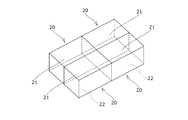
- heated materials 20 are packaged. Specifically, four heated materials 20 arranged adjacent to each other in the horizontal and vertical directions 2 ⁇ 2 are packaged by the package 30.
- a plurality of first metal openings 50 b are formed in the first metal layer 50, and the first metal outer periphery covering portion 50 a. Is formed so as to cover the outer peripheral edge of each material to be heated 20 with a central portion of each material 20 to be heated.
- a plurality of second metal openings 51 b are formed in the second metal layer 51, and the second metal outer peripheral edge covering portion 51 a opens the central portion of each heated material 20 and each heated material. The outer peripheral edge of 20 is formed.
- each of the first insulation layers 41 is formed with a plurality of first insulation layer openings 41b.
- the second insulation layer 42 made of PP has the plurality of second insulation layer openings 42b. Is formed.
- the four heated materials 20 are packaged by the packaging body 30, but the quantity and arrangement of the heated materials 20 packaged by the packaging body 30 may be arbitrary.
- a heating package 10 according to a third embodiment of the present invention will be described with reference to FIGS.
- the partial configuration is completely the same as that of the first embodiment described above, and therefore, the description of the configuration other than the difference is omitted.
- the packaging member 31 includes insulating layers 41 to 43 and metal layers 50 to 52.
- the insulating layers 41 to 43 are connected to the second insulating layer 42 arranged outside the second facing surface 22 and to each side of the second insulating layer 42 through a broken line portion. It has four side insulating layers 43 provided, and four flaps 41 c connected to one side of each side insulating layer 43.
- the second insulating layer 42, the side insulating layer 43, and the flap 41c are each formed in a rectangular shape.
- each of the flaps 41 c is connected to a side opposite to one side of the side insulating layer 43 provided with the second insulating layer 42 via a broken line portion, and the heated material 20.
- the first opposed surface 21 is disposed.
- the 1st insulating layer 41 which has the 1st insulating layer outer periphery cover part 41a and the 1st insulating layer opening part 41b is comprised from the four flaps 41c.
- the metal layer formed on each flap 41c constitutes the first metal layer 50 having the first metal outer peripheral edge covering portion 50a and the first metal opening portion 50b.
- the paper-made second insulating layer 42 is not formed with an opening, and the paper-made second insulating layer 42 covers the entire second opposing surface 22. It is formed so as to cover.
- the second metal layer 51 includes a second metal outer periphery covering portion 51a that covers the outer periphery of the second facing surface 22, and a second metal opening 51b formed inside the second metal outer periphery covering portion 51a.
- the second insulating layer 42 made of PP has a second insulating layer outer peripheral edge covering portion 42a covering the outer peripheral edge of the second facing surface 22 and a second insulating layer outer peripheral edge covering portion 42a formed inside the second insulating layer outer peripheral edge covering portion 42a. Two insulating layer openings 42b are formed.
- the metal layer formed on each of the side surface insulating layers 43 functions as a conduction part 52 that conducts the first metal layer 50 and the second metal layer 51.
- the cover member 32 is formed in a rectangular tube shape from an insulating sheet such as paper, and is formed so as to accommodate the heated material 20 wrapped by the packaging member 31 by being inserted from the side. ing.
- the specific aspect of the cover member 32 is not limited to the above.
- the cover member 32 is formed in a hexahedron shape with one surface open, and is covered with the material to be heated 20 wrapped by the packaging member 31 and accommodated from above. It can be anything.
- a heating package 10 according to a fourth embodiment of the present invention will be described with reference to FIGS.
- the partial configuration is completely the same as that of the first embodiment described above, and therefore, the description of the configuration other than the difference is omitted.
- the first insulating layer 41 is formed on the inner surface and the outer surface of the first metal layer 50, and the inner surface and the outer surface of the second metal layer 51 are formed.
- a second insulating layer 42 is formed on the side surface.
- the first insulating layer 41 on the inner surface of the first metal layer 50 and the second insulating layer 42 on the inner surface of the second metal layer 51 are made of PP, and the first insulating layer 41 on the outer surface of the first metal layer 50
- the first insulating layer 41 and the second insulating layer 42 on the outer surface of the second metal layer 51 are made of PET (polyethylene terephthalate).
- the package 30 is configured in a pouch shape by thermally bonding the outer edge portion of 42 with the heat bonding portion 46.
- the insulating layers 41 and 42 are bonded by heating, but the insulating layers 41 and 42 may be bonded by an adhesive.
- the first metal layer 50 includes the first metal outer peripheral edge covering portion 50 a and the first metal opening 50 b, and each first insulating layer 41. However, it has the 1st insulating layer outer periphery covering part 41a and the 1st insulating layer opening part 41b.
- the second metal layer 51 has a second metal outer peripheral edge covering portion 51 a and a second metal opening 51 b, and each second insulating layer 42 is outside the second insulating layer that covers the outer peripheral edge of the heated material 20.
- a peripheral cover 42a and a second insulating layer opening 42b are provided.
- the outer edge portion of the first metal layer 50 and the outer edge portion of the second metal layer 51 interpose the first insulating layer 41 and the second insulating layer 42 between each other. Are arranged adjacent to each other. As a result, the outer edge portion of the first metal layer 50 and the outer edge portion of the second metal layer 51 are electrically connected (with low impedance) through the thin insulating layers 41 and 42 of about 70 ⁇ m, respectively.
- the outer edge portions of the layers 50 and 51 function as the conduction portion 52.
- the first insulating layer 41 and the second insulating layer 42 are interposed between the conductive metal layers 51 and 52, but the first insulating layer 41 and the conductive metal layers 51 and 52 are interposed between the first insulating layer 41 and the conductive metal layers 51 and 52. Only one of the layer 41 or the second insulating layer 42 may be interposed.
- the outer edge portion of the first insulating layer 41 formed on the inner surface of the first metal layer 50 and the second insulating layer 42 formed on the inner surface of the second metal layer 51 are thermally bonded, in the modification shown in FIG. 14, the outer edge portion of the first insulating layer 41 formed on the inner surface of the first metal layer 50 and the outer surface of the second metal layer 51 are formed. Further, the outer edge portion of the second insulating layer 42 is thermally bonded. On the contrary, the outer edge portion of the first insulating layer 41 formed on the outer surface of the first metal layer 50 and the outer edge portion of the second insulating layer 42 formed on the inner surface of the second metal layer 51 are heated. It may be glued.
- the first experimental example was performed under the following conditions. Heated material 20: Frozen strawberry shortcake (length 120mm, width 70mm, height 34mm) Preheating temperature of the material to be heated 20: ⁇ 15 ° C.
- First electrode 60 Flat plate electrode
- Second electrode 61 Flat plate electrode High frequency dielectric heating condition Frequency: 13.56 MHz
- the package 30 of 1st Embodiment mentioned above was used. Specific conditions of the package 30 are as follows. Insulating layer on the outer side: paper (thickness 0.24 mm) Inner side insulation layer: polyethylene (thickness 17 ⁇ m) 1st metal layer 50, 2nd metal layer 51, conduction
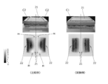
- the cover range of the to-be-heated material 20 by the 1st metal layer 50 (2nd metal layer 51) is different from the 1st experiment example mentioned above. That is, in the first experimental example, as shown by reference numeral C ⁇ b> 1 in FIG. 15, the first opposing surface 21 (second opposing surface 22) of the heated material 20 is formed by the first metal layer 50 (second metal layer 51). In contrast, in the comparative example, the first opposing surface 21 of the material to be heated 20 is covered by the first metal layer 50 (second metal layer 51) in the comparative example, as shown by reference numeral C2 in FIG. Only a part (left and right ends) of the outer peripheral edge of (second facing surface 22) was covered.
- the second experimental example was performed under the following conditions.
- Material to be heated 20 fillet (size: about 110 mm ⁇ 100 mm ⁇ 20 mm)
- Preheating temperature of the material 20 to be heated ⁇ 40 ° C.
- First electrode 60 Pin electrode Second electrode 61: Flat plate electrode High frequency dielectric heating condition Frequency: 13.56 MHz
- First insulating layer 41 on the outer surface side PET (thickness 12 ⁇ m)
- First insulating layer 41 on the inner side surface PP (thickness 70 ⁇ m)
- Second insulating layer 42 on the outer side surface PET (thickness 12 ⁇ m)
- Second insulating layer 42 on the inner side PP (thickness 70 ⁇ m)
- the heated material 20 was dielectrically heated without covering the heated material 20 with the package 30 or the like.
- the skin and bloody part are overheated and the white meat is not sufficiently thawed.
- the maximum temperature is 29.7 ° C. and the minimum temperature is ⁇ 0.3 ° C. It was found that the temperature difference became large.
- the heating package may be configured by arbitrarily combining the configurations of the above-described embodiments and modifications.
- the heated material has been described as a hexahedral frozen shortcake or the like.
- the specific shape of the heated material may be anything, and the type of the heated material Anything such as frozen tuna and frozen meat may be used.
- the packaging body is described as being formed from a laminate material in which a metal layer is attached to an insulating layer.
- the metal layer formed separately from the insulating layer is used as the insulating layer. You may arrange
- the insulating layer is formed on one of the inner surface or the outer surface of each metal layer. May be.
- the metal layer is attached to the surface of the insulating insulating layer by vapor deposition.
- any method for attaching the metal layer to the surface of the insulating layer may be used.
- the packaging aspect of the to-be-heated material by a package is for example, a gap may be formed between the first metal layer and the first facing surface of the heated material in a state where the heated material is packaged by the package.
- the insulating layer is described as being made of paper or synthetic resin.
- the specific material of the insulating portion may be anything as long as it has insulating properties.
- the specific type of metal forming the first metal layer, the second metal layer, and the conductive portion may be any material such as aluminum or copper as long as it has conductivity.
Landscapes
- Engineering & Computer Science (AREA)
- Food Science & Technology (AREA)
- Physics & Mathematics (AREA)
- Electromagnetism (AREA)
- Life Sciences & Earth Sciences (AREA)
- Mechanical Engineering (AREA)
- Package Specialized In Special Use (AREA)
- Cookers (AREA)
- Constitution Of High-Frequency Heating (AREA)
- Packages (AREA)
Abstract
加熱ムラの発生を回避しつつ、被加熱材を短時間で加熱することができ、しかも、加熱用パッケージのハンドリング性を向上する加熱用パッケージおよび包装体を提供すること。 第1電極(60)および第2電極(61)の間に配置され、高周波誘電加熱によって加熱される加熱用パッケージ(10)であって、加熱用パッケージ(10)が、被加熱材(20)と包装体(30)とから構成され、包装体(30)は、第1対向面(21)に配置される第1金属層(50)と、第2対向面(22)に配置される第2金属層(51)と、第1金属層(50)および第2金属層(51)を導通させる導通部(52)とを有し、第1金属層(50)は、第1対向面(21)の外周縁を覆う第1金属外周縁覆部(50a)と、第1金属外周縁覆部(50a)の内側に形成された第1金属開口部(50b)とを有している加熱用パッケージ(10)。
Description
本発明は、対向配置された第1電極および第2電極の間に配置され、高周波誘電加熱によって加熱される加熱用パッケージおよび包装体に関する。
従来、冷凍食品等の被加熱材を加熱する方法として、対向配置された第1電極および第2電極の間に配置された被加熱材を高周波誘電加熱によって加熱する方法が知られている。
このような高周波誘電加熱では、被加熱材の被誘電率・誘電体損失・電界強度等によって、単位体積当たりに吸収される高周波電力が決定されるため、1つの被加熱材内に発熱性の良い部分および発熱性の悪い部分が存在することになる。そのため、被加熱材の発熱性の悪い部分の解凍に合わせて誘電加熱すると、一定の加熱時間の経過後に発熱性の良い部分に発熱暴走が生じ、結果、被加熱材に加熱ムラが生じてしまうという問題があった。
そこで、従来、被加熱材に加熱ムラが生じることを解消する方策として、被加熱材に接触する温度センサーを複数個設け、この温度センサーが検出した一番低い箇所の温度と一番高い箇所の温度の差が一定以上開くと高周波発振器の出力を一定時間停止して、被加熱材自身の熱伝導を利用して加熱ムラを抑え、一定時間過ぎると出力をオンにし、被加熱材の一番高い箇所の温度が設定温度に達するまで、高周波発振器の出力のオン-オフを繰り替えして誘電加熱と熱伝導による自然解凍とを組み合わせで解凍する方法が提案されている(例えば特許文献1を参照)。
ところが、特許文献1に記載の方法は、被加熱材の複数箇所の温度を測定し、その温度差によって高周波発振器の出力のオン-オフを繰り返して部位の温度差を小さく維持しながら解凍するものであるため、解凍時間に長時間を要するという問題点があった。
そこで、本出願人は、上述した被加熱材に加熱ムラが生じることを解消する他の方策として、被加熱材であるショートケーキの先端部および後端部を、互いに導通された一対の金属層間に配置し、これら金属層によって電界遮蔽しつつ、被加熱材を誘電加熱することを提案した(特許文献2を参照)。このように、金属層による電界遮蔽を利用して被加熱材の加熱効率を調整することで、発熱性の良いショートケーキの先端部および後端部に発熱暴走が生じることを回避し、良好に安定して加熱することができる。
しかしながら、本出願人によって実施された研究・試験によって、被加熱材の先端部および後端部を金属層で遮蔽する特許文献2に記載の方法では、被加熱材の形状や種類によっては、被加熱材の外周縁(電極を対向させた方向に被加熱材を見た場合の外周縁)に発熱暴走が生じ、発熱暴走を生じた部分で、クリームの溶融等の品質の劣化が生じることが分かった。
また、被加熱材の先端部および後端部のみを金属層で遮蔽する特許文献2に記載の方法では、被加熱材に金属層を被せた状態で、被加熱材の底部が覆われておらず外部露出しているため、異物混入の虞や、加熱用パッケージのハンドリング性に難があるという問題もある。
そこで、本発明は、これらの問題点を解決するものであり、加熱ムラの発生を回避しつつ、被加熱材を短時間で加熱することができ、しかも、加熱用パッケージのハンドリング性を向上する加熱用パッケージおよび包装体を提供することを目的とする。
本発明の加熱用パッケージは、対向配置された第1電極および第2電極の間に配置され、高周波誘電加熱によって加熱される加熱用パッケージであって、前記加熱用パッケージは、被加熱材と、前記被加熱材を包む包装体とから構成され、前記被加熱材は、前記第1電極に対向して配置される第1対向面と、前記第2電極に対向して配置される第2対向面とを有し、前記包装体は、前記第1対向面に配置される第1金属層と、前記第2対向面に配置される第2金属層と、前記第1金属層および前記第2金属層を導通させる導通部とを有し、前記第1金属層は、前記第1対向面の外周縁を覆う第1金属外周縁覆部と、前記第1金属外周縁覆部の内側に形成された第1金属開口部とを有していることにより、前記課題を解決するものである。
また、本発明の包装体は、対向配置された第1電極および第2電極の間に配置され、高周波誘電加熱によって加熱される被加熱材を包む包装体であって、前記包装体は、前記第1電極に対向して配置される前記被加熱材の第1対向面に配置される第1金属層と、前記第2電極に対向して配置される前記被加熱材の第2対向面に配置される第2金属層と、前記第1金属層および前記第2金属層を導通させる導通部とを有し、前記第1金属層は、前記第1対向面の外周縁を覆う第1金属外周縁覆部と、前記第1金属外周縁覆部の内側に形成された第1金属開口部とを有していることにより、前記課題を解決するものである。
また、本発明の包装体は、対向配置された第1電極および第2電極の間に配置され、高周波誘電加熱によって加熱される被加熱材を包む包装体であって、前記包装体は、前記第1電極に対向して配置される前記被加熱材の第1対向面に配置される第1金属層と、前記第2電極に対向して配置される前記被加熱材の第2対向面に配置される第2金属層と、前記第1金属層および前記第2金属層を導通させる導通部とを有し、前記第1金属層は、前記第1対向面の外周縁を覆う第1金属外周縁覆部と、前記第1金属外周縁覆部の内側に形成された第1金属開口部とを有していることにより、前記課題を解決するものである。
本請求項1、4、10に係る発明によれば、被加熱材の第1対向面に配置される第1金属層が、第1対向面の外周縁を覆う第1金属外周縁覆部と、第1金属外周縁覆部の内側に形成された第1金属開口部とを有していることにより、電界が集中しがちな被加熱材の外周縁を第1金属外周縁覆部によって遮蔽することで、被加熱材の均一な加熱を実現して、被加熱材の品質の劣化を回避でき、また、被加熱材の外周縁への電界集中を回避することで、被加熱材に加熱ムラを生じさせることなく、誘電加熱の出力を高めることが可能であるため、短時間での被加熱材の加熱を実現することができる。
本請求項2に係る発明によれば、第1金属層の一部および第2金属層の一部を、相互間に第1絶縁層または第2絶縁層の少なくとも一方を介在させた状態で隣接して配置することで、導通部が形成されていることにより、金属層同士を直接接触させることなく、金属層間の導通部を形成するため、包装体の設計自由度を向上させることができる。
本請求項3に係る発明によれば、包装体は、第1金属層の内側面および外側面の両方に形成された第1絶縁層と、第2金属層の内側面または外側面の両方に形成された第2絶縁層を有していることにより、金属層が被加熱材に直接接触することを回避できるとともに、絶縁層によって金属層と電極との間を絶縁することが可能であるため、追加の絶縁部材を設ける必要がない。
本請求項5に係る発明によれば、被加熱材の第2対向面に配置される第2絶縁層が、第2対向面を全面的に覆うように形成されていることにより、異物混入の防止や、被加熱材の第2対向面側を下に向けた状態で加熱用パッケージを机等の上に置くことができる等、流通時や保管時等に被加熱材を収容する収容用筺体として包装体を機能させることができる。
本請求項6に係る発明によれば、被加熱材の第1対向面に形成された第1絶縁層が、第1絶縁層外周縁覆部の内側に形成された第1絶縁層開口部を有していることにより、第1金属層の第1金属開口部および第1絶縁層の第1絶縁層開口部を通して外部から被加熱材を視認することが可能であるため、被加熱材の種類や状態の確認を容易に行うことができる。
本請求項7に係る発明によれば、被加熱材の第1対向面に配置された第1絶縁層が、第1対向面を全面的に覆うように形成されていることにより、異物混入の防止や、被加熱材の第1対向面側を下方に向けた状態で加熱用パッケージを机等の上に置くことができる等、加熱用パッケージのハンドリング性を向上させることができる。
本請求項8に係る発明によれば、包装体が、第1金属層や第2金属層を有した包装部材とは別体に形成されたカバー部材を備えていることにより、被加熱材を包装する機能をカバー部材にも分担させることが可能であるため、例えば、包装部材を被加熱材から簡単に外すことが可能な形態で設計する等、包装部材の設計自由度を向上させることができる。
本請求項9に係る発明によれば、包装体が、第1対向面に配置される第1絶縁層と、第2対向面に配置される第2絶縁層と、被加熱材の対向する2つの側面に配置される2つの側面絶縁層とを有していることにより、定形性を有した箱として包装体を構成することができる。
本請求項3に係る発明によれば、包装体は、第1金属層の内側面および外側面の両方に形成された第1絶縁層と、第2金属層の内側面または外側面の両方に形成された第2絶縁層を有していることにより、金属層が被加熱材に直接接触することを回避できるとともに、絶縁層によって金属層と電極との間を絶縁することが可能であるため、追加の絶縁部材を設ける必要がない。
本請求項5に係る発明によれば、被加熱材の第2対向面に配置される第2絶縁層が、第2対向面を全面的に覆うように形成されていることにより、異物混入の防止や、被加熱材の第2対向面側を下に向けた状態で加熱用パッケージを机等の上に置くことができる等、流通時や保管時等に被加熱材を収容する収容用筺体として包装体を機能させることができる。
本請求項6に係る発明によれば、被加熱材の第1対向面に形成された第1絶縁層が、第1絶縁層外周縁覆部の内側に形成された第1絶縁層開口部を有していることにより、第1金属層の第1金属開口部および第1絶縁層の第1絶縁層開口部を通して外部から被加熱材を視認することが可能であるため、被加熱材の種類や状態の確認を容易に行うことができる。
本請求項7に係る発明によれば、被加熱材の第1対向面に配置された第1絶縁層が、第1対向面を全面的に覆うように形成されていることにより、異物混入の防止や、被加熱材の第1対向面側を下方に向けた状態で加熱用パッケージを机等の上に置くことができる等、加熱用パッケージのハンドリング性を向上させることができる。
本請求項8に係る発明によれば、包装体が、第1金属層や第2金属層を有した包装部材とは別体に形成されたカバー部材を備えていることにより、被加熱材を包装する機能をカバー部材にも分担させることが可能であるため、例えば、包装部材を被加熱材から簡単に外すことが可能な形態で設計する等、包装部材の設計自由度を向上させることができる。
本請求項9に係る発明によれば、包装体が、第1対向面に配置される第1絶縁層と、第2対向面に配置される第2絶縁層と、被加熱材の対向する2つの側面に配置される2つの側面絶縁層とを有していることにより、定形性を有した箱として包装体を構成することができる。
10 ・・・ 加熱用パッケージ
20 ・・・ 被加熱材
21 ・・・ 第1対向面
22 ・・・ 第2対向面
23 ・・・ 側面
30 ・・・ 包装体
31 ・・・ 包装部材
32 ・・・ カバー部材
41 ・・・ 第1絶縁層
41a ・・・ 第1絶縁層外周縁覆部
41b ・・・ 第1絶縁層開口部
41c ・・・ フラップ
42 ・・・ 第2絶縁層
42a ・・・ 第2絶縁層外周縁覆部
42b ・・・ 第2絶縁層開口部
43 ・・・ 側面絶縁層
44 ・・・ 第1側面フラップ
44a ・・・ 差込片
45 ・・・ 第2側面フラップ
45a ・・・ スリット
46 ・・・ 熱接着部
50 ・・・ 第1金属層
50a ・・・ 第1金属外周縁覆部
50b ・・・ 第1金属開口部
51 ・・・ 第2金属層
51a ・・・ 第2金属外周縁覆部
51b ・・・ 第2金属開口部
52 ・・・ 導通部
60 ・・・ 第1電極
61 ・・・ 第2電極
62 ・・・ 高周波電源
70 ・・・ 台紙
20 ・・・ 被加熱材
21 ・・・ 第1対向面
22 ・・・ 第2対向面
23 ・・・ 側面
30 ・・・ 包装体
31 ・・・ 包装部材
32 ・・・ カバー部材
41 ・・・ 第1絶縁層
41a ・・・ 第1絶縁層外周縁覆部
41b ・・・ 第1絶縁層開口部
41c ・・・ フラップ
42 ・・・ 第2絶縁層
42a ・・・ 第2絶縁層外周縁覆部
42b ・・・ 第2絶縁層開口部
43 ・・・ 側面絶縁層
44 ・・・ 第1側面フラップ
44a ・・・ 差込片
45 ・・・ 第2側面フラップ
45a ・・・ スリット
46 ・・・ 熱接着部
50 ・・・ 第1金属層
50a ・・・ 第1金属外周縁覆部
50b ・・・ 第1金属開口部
51 ・・・ 第2金属層
51a ・・・ 第2金属外周縁覆部
51b ・・・ 第2金属開口部
52 ・・・ 導通部
60 ・・・ 第1電極
61 ・・・ 第2電極
62 ・・・ 高周波電源
70 ・・・ 台紙
以下に、本発明の第1実施形態に係る加熱用パッケージ10について、図面に基づいて説明する。
まず、加熱用パッケージ10は、図1に示すように、対向配置された第1電極60および第2電極61の間に配置され、高周波誘電加熱によって加熱されるものであり、被加熱材20と、被加熱材20を包む包装体30とから構成されている。第1電極60および第2電極61は、高周波電源62に接続され、加熱用パッケージ10は、絶縁性の台紙70を介在させた状態で、第2電極61上に載置される。
被加熱材20は、図1~図3に示すように、六面体状の冷凍ショートケーキであり、第1電極60に対向して配置される第1対向面21と、第2電極61に対向して配置される第2対向面22と、4つの側面23とを有している。
包装体30は、紙等の絶縁性シートから成る絶縁層41~45の内側面に金属層50~52を蒸着によって付着させるとともに、金属層50~52の内側面にPP(ポリプロピレン)等の合成樹脂から成る絶縁層41~45を形成したラミネート材から形成されている。
絶縁層41~45は、図2や図4に示すように、箱状に組立可能なものであり、第1対向面21の外側に配置される第1絶縁層41と、第2対向面22の外側に配置される第2絶縁層42と、被加熱材20の側面23の外側に配置される側面絶縁層43と、第1絶縁層41に連設された第1側面フラップ44と、第2絶縁層42に連設された第2側面フラップ45とから構成されている。
第1絶縁層41、第2絶縁層42、側面絶縁層43、第1側面フラップ44、および、第2側面フラップ45は、それぞれ矩形状に形成されている。
第1絶縁層41、第2絶縁層42、側面絶縁層43、第1側面フラップ44、および、第2側面フラップ45は、それぞれ矩形状に形成されている。
側面絶縁層43は、図2や図4に示すように、第1絶縁層41の一辺および第2絶縁層42の一辺を連結している。
第1側面フラップ44は、側面絶縁層43が連設された第1絶縁層41の一辺の反対側の辺に折線部を介して連設され、側面絶縁層43が配置された被加熱材20の側面23の反対側の側面23に配置される。
第2側面フラップ45は、側面絶縁層43が連設された第2絶縁層42の一辺の反対側の辺に折線部を介して連設され、側面絶縁層43が配置された被加熱材20の側面23の反対側の側面23に配置される。
第1側面フラップ44および第2側面フラップ45は、互いに連結可能に形成され、具体的には、図4に示すように、第1側面フラップ44には、差込片44aが形成され、第2側面フラップ45には、第1側面フラップ44の差込片44aを挿入させるスリット45aが形成されている。このように、第1側面フラップ44および第2側面フラップ45は、共働して側面絶縁層43を構成する。
第1側面フラップ44は、側面絶縁層43が連設された第1絶縁層41の一辺の反対側の辺に折線部を介して連設され、側面絶縁層43が配置された被加熱材20の側面23の反対側の側面23に配置される。
第2側面フラップ45は、側面絶縁層43が連設された第2絶縁層42の一辺の反対側の辺に折線部を介して連設され、側面絶縁層43が配置された被加熱材20の側面23の反対側の側面23に配置される。
第1側面フラップ44および第2側面フラップ45は、互いに連結可能に形成され、具体的には、図4に示すように、第1側面フラップ44には、差込片44aが形成され、第2側面フラップ45には、第1側面フラップ44の差込片44aを挿入させるスリット45aが形成されている。このように、第1側面フラップ44および第2側面フラップ45は、共働して側面絶縁層43を構成する。
金属層50~52は、図1~図4に示すように、第1対向面21の外側に配置される第1金属層50と、第2対向面22の外側に配置される第2金属層51とを有している。
また、側面絶縁層43間に形成された金属層は、第1金属層50および第2金属層51を導通させる導通部52として機能する。
また、側面絶縁層43間に形成された金属層は、第1金属層50および第2金属層51を導通させる導通部52として機能する。
各第1絶縁層41の中央部には、図1、図2、図4に示すように、開口部が形成されており、各第1絶縁層41は、第1対向面21の外周縁を覆う第1絶縁層外周縁覆部41aと、第1絶縁層外周縁覆部41aの内側に形成された第1絶縁層開口部41bとを有している。
また、上記に伴って、第1金属層50の中央部には、図1、図2、図4に示すように、開口部が形成されており、第1金属層50は、第1対向面21の外周縁を覆う第1金属外周縁覆部50aと、第1金属外周縁覆部50aの内側に形成された第1金属開口部50bとを有している。
また、上記に伴って、第1金属層50の中央部には、図1、図2、図4に示すように、開口部が形成されており、第1金属層50は、第1対向面21の外周縁を覆う第1金属外周縁覆部50aと、第1金属外周縁覆部50aの内側に形成された第1金属開口部50bとを有している。
なお、本実施形態では、図4に示すように、各第1絶縁層41に第1絶縁層開口部41bを形成したが、図5に示す第1変形例のように、紙製の第1絶縁層41に第1絶縁層開口部41bを形成しなくてもよい。
また、紙製の第2絶縁層42には、図1、図2、図4に示すように、開口部が形成されておらず、紙製の第2絶縁層42は、第2対向面22を全面的に覆うように形成されている。
また、第2金属層51の中央部には、図1、図2、図4に示すように、蒸着された金属層を除去することによって開口部が形成されており、第2金属層51は、第2対向面22の外周縁を覆う第2金属外周縁覆部51aと、第2金属外周縁覆部51aの内側に形成された第2金属開口部51bとを有している。
また、金属層の除去に伴って、PP製の第2絶縁層42には、第2対向面22の外周縁を覆う第2絶縁層外周縁覆部42aと、第2絶縁層外周縁覆部42aの内側に形成された第2絶縁層開口部42bとが形成されている。
また、第2金属層51の中央部には、図1、図2、図4に示すように、蒸着された金属層を除去することによって開口部が形成されており、第2金属層51は、第2対向面22の外周縁を覆う第2金属外周縁覆部51aと、第2金属外周縁覆部51aの内側に形成された第2金属開口部51bとを有している。
また、金属層の除去に伴って、PP製の第2絶縁層42には、第2対向面22の外周縁を覆う第2絶縁層外周縁覆部42aと、第2絶縁層外周縁覆部42aの内側に形成された第2絶縁層開口部42bとが形成されている。
なお、本実施形態では、図4に示すように、第1金属層50および第2金属層51の両方に、第1金属開口部50bまたは第2金属開口部51bを形成したが、図6に示す第2変形例のように、第2金属層51に第2金属開口部51bを形成しなくてもよい。
また、本実施形態では、図4に示すように、紙製の第2絶縁層42に開口部を形成していないが、紙製の第2絶縁層42にも開口部を形成してもよい。
また、本実施形態では、図4に示すように、紙製の第2絶縁層42に開口部を形成していないが、紙製の第2絶縁層42にも開口部を形成してもよい。
次に、本発明の第2実施形態に係る加熱用パッケージ10について、図7~図9に基づいて説明する。ここで、第2実施形態では、一部構成については、前述した第1実施形態と全く同じであるため、相違点以外の構成については、その説明を省略する。
まず、上述した第1実施形態では、包装体30によって1つの被加熱材20を包装するものとして説明したが、第2実施形態では、図7や図8に示すように、包装体30によって複数(4つ)の被加熱材20を包装しており、具体的には、水平方向に縦横2×2で隣接して配置された4つの被加熱材20を包装体30によって包装している。
また、包装体30によって包装する被加熱材20が複数であることに対応して、第1金属層50には、複数の第1金属開口部50bが形成され、第1金属外周縁覆部50aは、各被加熱材20の中央部を空けて各被加熱材20の外周縁を覆うように形成されている。
また、同様に、第2金属層51には、複数の第2金属開口部51bが形成され、第2金属外周縁覆部51aは、各被加熱材20の中央部を空けて各被加熱材20の外周縁を覆うように形成されている。
また、上述したように第1金属層50に複数の第1金属開口部50bが形成されることに伴って、各第1絶縁層41には、複数の第1絶縁層開口部41bが形成されている。
また、上述したように第2金属層51に複数の第2金属開口部51bが形成されることに伴って、PP製の第2絶縁層42には、複数の第2絶縁層開口部42bが形成されている。
また、同様に、第2金属層51には、複数の第2金属開口部51bが形成され、第2金属外周縁覆部51aは、各被加熱材20の中央部を空けて各被加熱材20の外周縁を覆うように形成されている。
また、上述したように第1金属層50に複数の第1金属開口部50bが形成されることに伴って、各第1絶縁層41には、複数の第1絶縁層開口部41bが形成されている。
また、上述したように第2金属層51に複数の第2金属開口部51bが形成されることに伴って、PP製の第2絶縁層42には、複数の第2絶縁層開口部42bが形成されている。
なお、上述した実施形態では、包装体30によって4つの被加熱材20を包装するものとして説明したが、包装体30によって包装する被加熱材20の数量や配置は、如何なるものでもよい。
次に、本発明の第3実施形態に係る加熱用パッケージ10について、図10および図11に基づいて説明する。ここで、第3実施形態では、一部構成については、前述した第1実施形態と全く同じであるため、相違点以外の構成については、その説明を省略する。
まず、上述した第1実施形態では、包装体30が、単一の部材から構成されているものとして説明したが、第3実施形態では、包装体30が、図10に示すように、被加熱材20を包む包装部材31と、包装部材31とは別体に形成され包装部材31に被せられるカバー部材32の複数(2つ)の部材から構成されている。
包装部材31は、絶縁層41~43と、金属層50~52とから構成されている。
絶縁層41~43は、図10や図11に示すように、第2対向面22の外側に配置される第2絶縁層42と、第2絶縁層42の各辺に折線部を介して連設された4つの側面絶縁層43と、各側面絶縁層43の一辺に連設された4つのフラップ41cとを有している。
第2絶縁層42、側面絶縁層43、および、フラップ41cは、それぞれ矩形状に形成されている。
第2絶縁層42、側面絶縁層43、および、フラップ41cは、それぞれ矩形状に形成されている。
各フラップ41cは、図10や図11に示すように、第2絶縁層42が連設された側面絶縁層43の一辺の反対側の辺に折線部を介して連設され、被加熱材20の第1対向面21に配置される。これにより、本実施形態では、4つのフラップ41cから、第1絶縁層外周縁覆部41aおよび第1絶縁層開口部41bを有した第1絶縁層41が構成されている。
また、各フラップ41cに形成された金属層によって、第1金属外周縁覆部50aおよび第1金属開口部50bを有した第1金属層50が構成されている。
また、各フラップ41cに形成された金属層によって、第1金属外周縁覆部50aおよび第1金属開口部50bを有した第1金属層50が構成されている。
また、紙製の第2絶縁層42には、図10や図11に示すように、開口部が形成されておらず、紙製の第2絶縁層42は、第2対向面22を全面的に覆うように形成されている。
また、第2金属層51は、第2対向面22の外周縁を覆う第2金属外周縁覆部51aと、第2金属外周縁覆部51aの内側に形成された第2金属開口部51bとを有している。
また、PP製の第2絶縁層42には、第2対向面22の外周縁を覆う第2絶縁層外周縁覆部42aと、第2絶縁層外周縁覆部42aの内側に形成された第2絶縁層開口部42bとが形成されている。
また、第2金属層51は、第2対向面22の外周縁を覆う第2金属外周縁覆部51aと、第2金属外周縁覆部51aの内側に形成された第2金属開口部51bとを有している。
また、PP製の第2絶縁層42には、第2対向面22の外周縁を覆う第2絶縁層外周縁覆部42aと、第2絶縁層外周縁覆部42aの内側に形成された第2絶縁層開口部42bとが形成されている。
また、各側面絶縁層43に形成された金属層は、第1金属層50および第2金属層51を導通させる導通部52として機能する。
カバー部材32は、図10に示すように、紙等の絶縁性シートから四角筒状に形成され、包装部材31によって包まれた被加熱材20を側方から挿入させて収容するように形成されている。
なお、カバー部材32の具体的態様は上記に限定されず、例えば、一面が開放した六面体状に形成され、包装部材31によって包まれた被加熱材20に上方から被せられて収容するもの等、如何なるものでもよい。
なお、カバー部材32の具体的態様は上記に限定されず、例えば、一面が開放した六面体状に形成され、包装部材31によって包まれた被加熱材20に上方から被せられて収容するもの等、如何なるものでもよい。
次に、本発明の第4実施形態に係る加熱用パッケージ10について、図12および図13に基づいて説明する。ここで、第4実施形態では、一部構成については、前述した第1実施形態と全く同じであるため、相違点以外の構成については、その説明を省略する。
まず、第4実施形態では、図13に示すように、第1金属層50の内側面および外側面に、第1絶縁層41が形成されているとともに、第2金属層51の内側面および外側面に、第2絶縁層42が形成されている。
第1金属層50の内側面の第1絶縁層41、および、第2金属層51の内側面の第2絶縁層42は、PPから形成され、また、第1金属層50の外側面の第1絶縁層41、および、第2金属層51の外側面の第2絶縁層42は、PET(ポリエチレンテレフタラート)から形成されている。
第1金属層50の内側面の第1絶縁層41、および、第2金属層51の内側面の第2絶縁層42は、PPから形成され、また、第1金属層50の外側面の第1絶縁層41、および、第2金属層51の外側面の第2絶縁層42は、PET(ポリエチレンテレフタラート)から形成されている。
そして、図12や図13に示すように、第1金属層50の内側面に形成された第1絶縁層41の外縁部と、第2金属層51の内側面に形成された第2絶縁層42の外縁部とを、熱接着部46によって熱接着することにより、包装体30がパウチ状に構成されている。
なお、本実施形態では、加熱することで絶縁層41、42間を接着したが、接着剤によって絶縁層41、42を接着してもよい。
なお、本実施形態では、加熱することで絶縁層41、42間を接着したが、接着剤によって絶縁層41、42を接着してもよい。
また、第4実施形態では、図12や図13に示すように、第1金属層50が、第1金属外周縁覆部50aおよび第1金属開口部50bを有するとともに、各第1絶縁層41が、第1絶縁層外周縁覆部41aおよび第1絶縁層開口部41bを有している。
また、第2金属層51が、第2金属外周縁覆部51aおよび第2金属開口部51bを有するとともに、各第2絶縁層42が、被加熱材20の外周縁を覆う第2絶縁層外周縁覆部42aおよび第2絶縁層開口部42bを有している。
また、第2金属層51が、第2金属外周縁覆部51aおよび第2金属開口部51bを有するとともに、各第2絶縁層42が、被加熱材20の外周縁を覆う第2絶縁層外周縁覆部42aおよび第2絶縁層開口部42bを有している。
第4実施形態では、図13に示すように、第1金属層50の外縁部と第2金属層51の外縁部とが、第1絶縁層41および第2絶縁層42を相互間に介在させた状態で隣接して配置されている。これにより、これら第1金属層50の外縁部と第2金属層51の外縁部とは、それぞれ約70μm程度の薄い絶縁層41、42を介して(低インピーダンスで)導通し、換言すると、金属層50、51の外縁部が導通部52として機能している。
なお、本実施形態では、導通する金属層51、52の間に、第1絶縁層41および第2絶縁層42が介在しているが、導通する金属層51、52の間に、第1絶縁層41または第2絶縁層42の一方のみを介在させてもよい。
なお、本実施形態では、導通する金属層51、52の間に、第1絶縁層41および第2絶縁層42が介在しているが、導通する金属層51、52の間に、第1絶縁層41または第2絶縁層42の一方のみを介在させてもよい。
次に、第4実施形態の変形例について、図14に基づいて以下に説明する。
図13に示す第4実施形態では、第1金属層50の内側面に形成された第1絶縁層41の外縁部と、第2金属層51の内側面に形成された第2絶縁層42の外縁部とを熱接着したが、図14に示す変形例では、第1金属層50の内側面に形成された第1絶縁層41の外縁部と、第2金属層51の外側面に形成された第2絶縁層42の外縁部とを熱接着している。
なお、反対に、第1金属層50の外側面に形成された第1絶縁層41の外縁部と、第2金属層51の内側面に形成された第2絶縁層42の外縁部とを熱接着してもよい。
なお、反対に、第1金属層50の外側面に形成された第1絶縁層41の外縁部と、第2金属層51の内側面に形成された第2絶縁層42の外縁部とを熱接着してもよい。
以下に、本発明の第1実験例について、図15に基づいて説明する。
第1実験例は、以下の条件で行った。
被加熱材20:冷凍イチゴショートケーキ(長さ120mm、幅70mm、高さ34mm)
被加熱材20の加熱前温度:-15℃
第1電極60:平板電極
第2電極61:平板電極
高周波誘電加熱条件
周波数:13.56MHz
出力:230W
加熱時間:8分
被加熱材20:冷凍イチゴショートケーキ(長さ120mm、幅70mm、高さ34mm)
被加熱材20の加熱前温度:-15℃
第1電極60:平板電極
第2電極61:平板電極
高周波誘電加熱条件
周波数:13.56MHz
出力:230W
加熱時間:8分
また、包装体30については、上述した第1実施形態の包装体30を使用した。包装体30の具体的条件は、以下の通りである。
外側面側の絶縁層:紙(厚さ0.24mm)
内側面側の絶縁層:ポリエチレン(厚さ17μm)
第1金属層50、第2金属層51、導通部52:アルミニウム(厚さ7μm)
第1金属外周縁覆部50a、第2金属外周縁覆部51aの幅:10mm
外側面側の絶縁層:紙(厚さ0.24mm)
内側面側の絶縁層:ポリエチレン(厚さ17μm)
第1金属層50、第2金属層51、導通部52:アルミニウム(厚さ7μm)
第1金属外周縁覆部50a、第2金属外周縁覆部51aの幅:10mm
また、比較例については、第1金属層50(第2金属層51)による被加熱材20のカバー範囲のみが、上述した第1実験例と相違している。
すなわち、第1実験例においては、図15の符号C1に示すように、第1金属層50(第2金属層51)によって、被加熱材20の第1対向面21(第2対向面22)の外周縁全体をカバーしたのに対して、比較例では、図15の符号C2に示すように、第1金属層50(第2金属層51)によって、被加熱材20の第1対向面21(第2対向面22)の外周縁のうち一部分(左右両端)のみをカバーした。
すなわち、第1実験例においては、図15の符号C1に示すように、第1金属層50(第2金属層51)によって、被加熱材20の第1対向面21(第2対向面22)の外周縁全体をカバーしたのに対して、比較例では、図15の符号C2に示すように、第1金属層50(第2金属層51)によって、被加熱材20の第1対向面21(第2対向面22)の外周縁のうち一部分(左右両端)のみをカバーした。
上記条件で実験を行った結果、第1実験例では、被加熱材20が約8分で解凍されることが確認された。また、図15に示すように、加熱後における被加熱材20の断面の温度分布が均一であり、クリーム溶融等の品質劣化が生じないことが確認された。
他方、比較例では、図15の符号Mに示すように、被加熱材20の第1対向面21の外周縁のうち、第1金属層50によってカバーされていない部分の温度が高くなり、クリーム溶融が生じることが確認された。
次に、本発明の第2実験例について、図16に基づいて説明する。
第2実験例は、以下の条件で行った。
被加熱材20:ぶり切り身(大きさ約110mm×100mm×20mm)
被加熱材20の加熱前温度:-40℃
第1電極60:ピン電極
第2電極61:平板電極
高周波誘電加熱条件
周波数:13.56MHz
出力:500W
加熱時間:10分
被加熱材20:ぶり切り身(大きさ約110mm×100mm×20mm)
被加熱材20の加熱前温度:-40℃
第1電極60:ピン電極
第2電極61:平板電極
高周波誘電加熱条件
周波数:13.56MHz
出力:500W
加熱時間:10分
また、包装体30については、上述した第4実施形態の包装体30を使用した。包装体30の具体的条件は、以下の通りである。
外側面側の第1絶縁層41:PET(厚さ12μm)
内側面側の第1絶縁層41:PP(厚さ70μm)
外側面側の第2絶縁層42:PET(厚さ12μm)
内側面側の第2絶縁層42:PP(厚さ70μm)
第1金属層50、第2金属層51:アルミニウム(厚さ20μm)
第1金属外周縁覆部50a、第2金属外周縁覆部51aの幅:20mm
外側面側の第1絶縁層41:PET(厚さ12μm)
内側面側の第1絶縁層41:PP(厚さ70μm)
外側面側の第2絶縁層42:PET(厚さ12μm)
内側面側の第2絶縁層42:PP(厚さ70μm)
第1金属層50、第2金属層51:アルミニウム(厚さ20μm)
第1金属外周縁覆部50a、第2金属外周縁覆部51aの幅:20mm
また、比較例については、被加熱材20を包装体30等で覆うことなく、被加熱材20を誘電加熱した。
上記条件で実験を行った結果、第2実験例では、図16に示すように、金属外周縁覆部50a、51aに対応する位置の、皮や血合いは過加熱が抑制され、また、金属開口部50b、51bに対応する位置の、解けにくい白身部分は解凍され、その結果、最高温度:16.5℃、最低温度3.3℃と、温度差が小さくなることが分かった。
他方、比較例では、図16に示すように、皮や血合い部分が過加熱され、白身は充分に解凍されておらず、その結果、最高温度:29.7℃、最低温度-0.3℃と、温度差が大くなることが分かった。
以上、本発明の実施形態を詳述したが、本発明は上記実施形態に限定されるものではなく、請求の範囲に記載された本発明を逸脱することなく種々の設計変更を行なうことが可能である。
例えば、上述した複数の実施形態や変形例の各構成を、任意に組み合わせて加熱用パッケージを構成しても何ら構わない。
また、上述した実施形態では、被加熱材が六面体状の冷凍ショートケーキ等であるとして説明したが、被加熱材の具体的形状については如何なるものでもよく、また、被加熱材の種類についても、冷凍マグロや冷凍精肉等、如何なるものでもよい。
また、上述した実施形態では、包装体が、絶縁層に金属層を付着させたラミネート材から形成されているものとして説明したが、絶縁層とは別体に形成された金属層を絶縁層の内側面または外側面に配置してもよい。また、絶縁層を設けることなく、包装体を金属層のみから構成してもよい。
また、上述した実施形態では、各金属層の内側面および外側面の両方に絶縁層が形成されているものとして説明したが、各金属層の内側面または外側面の一方に絶縁層を形成してもよい。
また、上述した実施形態では、絶縁性の絶縁層の表面に金属層を蒸着によって付着させるものとして説明したが、絶縁層の表面への金属層の付着方法については如何なるものでもよい。
また、上述した実施形態では、包装体と被加熱材との間に隙間が生じないように、包装体によって被加熱材を包装するものとして説明したが、包装体による被加熱材の包装態様は上記に限定されず、例えば、包装体によって被加熱材を包装した状態で、第1金属層と被加熱材の第1対向面との間に隙間が生じていてもよい。
また、上述した実施形態では、絶縁層が、紙製や合成樹脂製であるものとして説明したが、絶縁部の具体的材料については、絶縁性を有したものであれば、如何なるものでもよい。
また、第1金属層や第2金属層や導通部を形成する金属の具体的種類は、導電性を有するものであれば、アルミニウムや銅等、如何なるものでもよい。
また、上述した実施形態では、被加熱材が六面体状の冷凍ショートケーキ等であるとして説明したが、被加熱材の具体的形状については如何なるものでもよく、また、被加熱材の種類についても、冷凍マグロや冷凍精肉等、如何なるものでもよい。
また、上述した実施形態では、包装体が、絶縁層に金属層を付着させたラミネート材から形成されているものとして説明したが、絶縁層とは別体に形成された金属層を絶縁層の内側面または外側面に配置してもよい。また、絶縁層を設けることなく、包装体を金属層のみから構成してもよい。
また、上述した実施形態では、各金属層の内側面および外側面の両方に絶縁層が形成されているものとして説明したが、各金属層の内側面または外側面の一方に絶縁層を形成してもよい。
また、上述した実施形態では、絶縁性の絶縁層の表面に金属層を蒸着によって付着させるものとして説明したが、絶縁層の表面への金属層の付着方法については如何なるものでもよい。
また、上述した実施形態では、包装体と被加熱材との間に隙間が生じないように、包装体によって被加熱材を包装するものとして説明したが、包装体による被加熱材の包装態様は上記に限定されず、例えば、包装体によって被加熱材を包装した状態で、第1金属層と被加熱材の第1対向面との間に隙間が生じていてもよい。
また、上述した実施形態では、絶縁層が、紙製や合成樹脂製であるものとして説明したが、絶縁部の具体的材料については、絶縁性を有したものであれば、如何なるものでもよい。
また、第1金属層や第2金属層や導通部を形成する金属の具体的種類は、導電性を有するものであれば、アルミニウムや銅等、如何なるものでもよい。
Claims (10)
- 対向配置された第1電極および第2電極の間に配置され、高周波誘電加熱によって加熱される加熱用パッケージであって、
前記加熱用パッケージは、被加熱材と、前記被加熱材を包む包装体とから構成され、
前記被加熱材は、前記第1電極に対向して配置される第1対向面と、前記第2電極に対向して配置される第2対向面とを有し、
前記包装体は、前記第1対向面に配置される第1金属層と、前記第2対向面に配置される第2金属層と、前記第1金属層および前記第2金属層を導通させる導通部とを有し、
前記第1金属層は、前記第1対向面の外周縁を覆う第1金属外周縁覆部と、前記第1金属外周縁覆部の内側に形成された第1金属開口部とを有していることを特徴とする加熱用パッケージ。 - 前記包装体は、前記第1金属層の内側面または外側面の少なくとも一方に形成された第1絶縁層と、前記第2金属層の内側面または外側面の少なくとも一方に形成された第2絶縁層を有し、
前記第1金属層の一部および前記第2金属層の一部を、相互間に前記第1絶縁層または前記第2絶縁層の少なくとも一方を介在させた状態で隣接して配置することで、前記導通部が形成されていることを特徴とする請求項1に記載の加熱用パッケージ。 - 前記包装体は、前記第1金属層の内側面および外側面の両方に形成された第1絶縁層と、前記第2金属層の内側面または外側面の両方に形成された第2絶縁層を有していることを特徴とする請求項1または請求項2に記載の加熱用パッケージ。
- 前記第2金属層は、前記第2対向面の外周縁を覆う第2金属外周縁覆部と、前記第2金属外周縁覆部の内側に形成された第2金属開口部とを有していることを特徴とする請求項1乃至請求項3のいずれかに記載の加熱用パッケージ。
- 前記包装体は、前記第2金属層の内側面または外側面の少なくとも一方に形成された第2絶縁層を有し、
前記第2絶縁層の少なくとも1つは、前記第2対向面を全面的に覆うように形成されていることを特徴とする請求項1乃至請求項4のいずれかに記載の加熱用パッケージ。 - 前記包装体は、前記第1金属層の内側面または外側面の少なくとも一方に形成された第1絶縁層を有し、
前記第1絶縁層は、前記第1対向面の外周縁を覆う第1絶縁層外周縁覆部と、前記第1絶縁層外周縁覆部の内側に形成された第1絶縁層開口部とを有していることを特徴とする請求項1乃至請求項5のいずれかに記載の加熱用パッケージ。 - 前記包装体は、前記第1金属層の内側面または外側面の少なくとも一方に形成された第1絶縁層を有し、
前記第1絶縁層の少なくとも1つは、前記第1対向面を全面的に覆うように形成されていることを特徴とする請求項1乃至請求項5のいずれかに記載の加熱用パッケージ。 - 前記包装体は、前記被加熱材を包む包装部材と、前記包装部材とは別体に形成され前記包装部材に被せられるカバー部材とから構成され、
前記包装部材は、前記第1金属層と前記第2金属層と前記導通部とを有することを特徴とする請求項1乃至請求項7のいずれかに記載の加熱用パッケージ。 - 前記包装体は、前記第1対向面に配置される第1絶縁層と、前記第2対向面に配置される第2絶縁層と、前記被加熱材の対向する2つの側面に配置され前記第1絶縁層および前記第2絶縁層を連結する2つの側面絶縁層とを有し、
前記第1金属層は、前記第1絶縁層の内側面または外側面に形成され、
前記第2金属層は、前記第2絶縁層の内側面または外側面に形成され、
前記導通部は、前記2つの側面絶縁層のうち少なくとも一方の内側面または外側面に形成された金属層から構成されていることを特徴とする請求項1乃至請求項8のいずれかに記載の加熱用パッケージ。 - 対向配置された第1電極および第2電極の間に配置され、高周波誘電加熱によって加熱される被加熱材を包む包装体であって、
前記包装体は、前記第1電極に対向して配置される前記被加熱材の第1対向面に配置される第1金属層と、前記第2電極に対向して配置される前記被加熱材の第2対向面に配置される第2金属層と、前記第1金属層および前記第2金属層を導通させる導通部とを有し、
前記第1金属層は、前記第1対向面の外周縁を覆う第1金属外周縁覆部と、前記第1金属外周縁覆部の内側に形成された第1金属開口部とを有していることを特徴とする包装体。
Applications Claiming Priority (2)
| Application Number | Priority Date | Filing Date | Title |
|---|---|---|---|
| JP2016047092A JP2017158850A (ja) | 2016-03-10 | 2016-03-10 | 加熱用パッケージおよび包装体 |
| JP2016-047092 | 2016-03-10 |
Publications (1)
| Publication Number | Publication Date |
|---|---|
| WO2017154648A1 true WO2017154648A1 (ja) | 2017-09-14 |
Family
ID=59789920
Family Applications (1)
| Application Number | Title | Priority Date | Filing Date |
|---|---|---|---|
| PCT/JP2017/007602 Ceased WO2017154648A1 (ja) | 2016-03-10 | 2017-02-28 | 加熱用パッケージおよび包装体 |
Country Status (2)
| Country | Link |
|---|---|
| JP (1) | JP2017158850A (ja) |
| WO (1) | WO2017154648A1 (ja) |
Citations (10)
| Publication number | Priority date | Publication date | Assignee | Title |
|---|---|---|---|---|
| JPS5614545B2 (ja) * | 1973-11-15 | 1981-04-04 | ||
| JPS5985280A (ja) * | 1982-11-08 | 1984-05-17 | Matsushita Electric Ind Co Ltd | 調理器具 |
| JPS6024704B2 (ja) * | 1982-06-11 | 1985-06-14 | 株式会社ニチレイ | 包装食品のマイクロ波による加熱殺菌法 |
| JPS62133694A (ja) * | 1985-12-06 | 1987-06-16 | 旭化成株式会社 | 合成樹脂板の高周波誘電加熱法 |
| JPH0383562A (ja) * | 1989-08-28 | 1991-04-09 | House Food Ind Co Ltd | 電子レンジ用食品 |
| JPH06193887A (ja) * | 1992-12-21 | 1994-07-15 | Mitsubishi Materials Corp | 加熱調理器具 |
| JPH06237707A (ja) * | 1993-02-16 | 1994-08-30 | Toppan Printing Co Ltd | マイクロ波加熱用支持体、およびこれを利用した加熱方法、ならびにマイクロ波加熱装置 |
| WO1999061346A1 (en) * | 1998-05-27 | 1999-12-02 | Morinaga Milk Industry Co., Ltd. | Packaging material and container for sealing beverage and food |
| JP2004135876A (ja) * | 2002-10-17 | 2004-05-13 | Toyo Ekco Kk | 電子レンジ用調理補助具及びそれを用いた食品の加熱方法 |
| JP2015159104A (ja) * | 2014-01-27 | 2015-09-03 | 東洋製罐グループホールディングス株式会社 | 被加熱材の加熱方法 |
-
2016
- 2016-03-10 JP JP2016047092A patent/JP2017158850A/ja active Pending
-
2017
- 2017-02-28 WO PCT/JP2017/007602 patent/WO2017154648A1/ja not_active Ceased
Patent Citations (10)
| Publication number | Priority date | Publication date | Assignee | Title |
|---|---|---|---|---|
| JPS5614545B2 (ja) * | 1973-11-15 | 1981-04-04 | ||
| JPS6024704B2 (ja) * | 1982-06-11 | 1985-06-14 | 株式会社ニチレイ | 包装食品のマイクロ波による加熱殺菌法 |
| JPS5985280A (ja) * | 1982-11-08 | 1984-05-17 | Matsushita Electric Ind Co Ltd | 調理器具 |
| JPS62133694A (ja) * | 1985-12-06 | 1987-06-16 | 旭化成株式会社 | 合成樹脂板の高周波誘電加熱法 |
| JPH0383562A (ja) * | 1989-08-28 | 1991-04-09 | House Food Ind Co Ltd | 電子レンジ用食品 |
| JPH06193887A (ja) * | 1992-12-21 | 1994-07-15 | Mitsubishi Materials Corp | 加熱調理器具 |
| JPH06237707A (ja) * | 1993-02-16 | 1994-08-30 | Toppan Printing Co Ltd | マイクロ波加熱用支持体、およびこれを利用した加熱方法、ならびにマイクロ波加熱装置 |
| WO1999061346A1 (en) * | 1998-05-27 | 1999-12-02 | Morinaga Milk Industry Co., Ltd. | Packaging material and container for sealing beverage and food |
| JP2004135876A (ja) * | 2002-10-17 | 2004-05-13 | Toyo Ekco Kk | 電子レンジ用調理補助具及びそれを用いた食品の加熱方法 |
| JP2015159104A (ja) * | 2014-01-27 | 2015-09-03 | 東洋製罐グループホールディングス株式会社 | 被加熱材の加熱方法 |
Also Published As
| Publication number | Publication date |
|---|---|
| JP2017158850A (ja) | 2017-09-14 |
Similar Documents
| Publication | Publication Date | Title |
|---|---|---|
| US5322984A (en) | Antenna for microwave enhanced cooking | |
| US4060443A (en) | Device for the heat-sealing of thermoplastic material or paper material coated with thermoplastics | |
| JP2023120196A (ja) | 電子レンジ対応食品の包装容器 | |
| US9676539B2 (en) | Package for combined steam and microwave heating of food | |
| JP6379221B2 (ja) | ラミネート部材の複数層を熱融着する方法及び装置 | |
| US9876481B2 (en) | Microwave processing device | |
| CN104812680B (zh) | 柔性盖 | |
| CN104736442B (zh) | 具有刻线的容器 | |
| CN105026128A (zh) | 超声波发生器 | |
| JPH02500970A (ja) | 食料品を収容した包装容器、この包装容器の製造方法、およびこの包装容器のアーク放電を排除する方法 | |
| EP3464113A1 (en) | Microwave packaging material | |
| WO2020157813A1 (ja) | 香味吸引器 | |
| WO2017154648A1 (ja) | 加熱用パッケージおよび包装体 | |
| CN212557436U (zh) | 一种相变材料保温箱 | |
| JP5138468B2 (ja) | 誘導加熱発熱体及び誘導加熱容器 | |
| JP6497038B2 (ja) | 被加熱材の加熱方法 | |
| US20220330390A1 (en) | Multi-dimension heated packages and vessels | |
| JP6115325B2 (ja) | 誘導加熱発熱具 | |
| JP6693304B2 (ja) | パウチ | |
| CA2867103C (en) | Packaging having field modifiers for improved microwave heating of cone-shaped products | |
| US8426785B2 (en) | Microwave field director structure with vanes having a conductive material thereon | |
| KR102057903B1 (ko) | 조리기기 | |
| CN104822595B (zh) | 一种包装机器用加热器结构 | |
| JPH0240854Y2 (ja) | ||
| JP2026500965A (ja) | エアロゾル生成システム |
Legal Events
| Date | Code | Title | Description |
|---|---|---|---|
| NENP | Non-entry into the national phase |
Ref country code: DE |
|
| 121 | Ep: the epo has been informed by wipo that ep was designated in this application |
Ref document number: 17762988 Country of ref document: EP Kind code of ref document: A1 |
|
| 122 | Ep: pct application non-entry in european phase |
Ref document number: 17762988 Country of ref document: EP Kind code of ref document: A1 |