WO2017154471A1 - 横断判定装置 - Google Patents
横断判定装置 Download PDFInfo
- Publication number
- WO2017154471A1 WO2017154471A1 PCT/JP2017/005189 JP2017005189W WO2017154471A1 WO 2017154471 A1 WO2017154471 A1 WO 2017154471A1 JP 2017005189 W JP2017005189 W JP 2017005189W WO 2017154471 A1 WO2017154471 A1 WO 2017154471A1
- Authority
- WO
- WIPO (PCT)
- Prior art keywords
- crossing
- yaw rate
- host vehicle
- speed
- unit
- Prior art date
- Legal status (The legal status is an assumption and is not a legal conclusion. Google has not performed a legal analysis and makes no representation as to the accuracy of the status listed.)
- Ceased
Links
Images


Classifications
-
- B—PERFORMING OPERATIONS; TRANSPORTING
- B60—VEHICLES IN GENERAL
- B60W—CONJOINT CONTROL OF VEHICLE SUB-UNITS OF DIFFERENT TYPE OR DIFFERENT FUNCTION; CONTROL SYSTEMS SPECIALLY ADAPTED FOR HYBRID VEHICLES; ROAD VEHICLE DRIVE CONTROL SYSTEMS FOR PURPOSES NOT RELATED TO THE CONTROL OF A PARTICULAR SUB-UNIT
- B60W30/00—Purposes of road vehicle drive control systems not related to the control of a particular sub-unit, e.g. of systems using conjoint control of vehicle sub-units
- B60W30/08—Active safety systems predicting or avoiding probable or impending collision or attempting to minimise its consequences
- B60W30/095—Predicting travel path or likelihood of collision
- B60W30/0956—Predicting travel path or likelihood of collision the prediction being responsive to traffic or environmental parameters
-
- B—PERFORMING OPERATIONS; TRANSPORTING
- B60—VEHICLES IN GENERAL
- B60W—CONJOINT CONTROL OF VEHICLE SUB-UNITS OF DIFFERENT TYPE OR DIFFERENT FUNCTION; CONTROL SYSTEMS SPECIALLY ADAPTED FOR HYBRID VEHICLES; ROAD VEHICLE DRIVE CONTROL SYSTEMS FOR PURPOSES NOT RELATED TO THE CONTROL OF A PARTICULAR SUB-UNIT
- B60W30/00—Purposes of road vehicle drive control systems not related to the control of a particular sub-unit, e.g. of systems using conjoint control of vehicle sub-units
- B60W30/08—Active safety systems predicting or avoiding probable or impending collision or attempting to minimise its consequences
- B60W30/095—Predicting travel path or likelihood of collision
-
- B—PERFORMING OPERATIONS; TRANSPORTING
- B60—VEHICLES IN GENERAL
- B60W—CONJOINT CONTROL OF VEHICLE SUB-UNITS OF DIFFERENT TYPE OR DIFFERENT FUNCTION; CONTROL SYSTEMS SPECIALLY ADAPTED FOR HYBRID VEHICLES; ROAD VEHICLE DRIVE CONTROL SYSTEMS FOR PURPOSES NOT RELATED TO THE CONTROL OF A PARTICULAR SUB-UNIT
- B60W30/00—Purposes of road vehicle drive control systems not related to the control of a particular sub-unit, e.g. of systems using conjoint control of vehicle sub-units
- B60W30/08—Active safety systems predicting or avoiding probable or impending collision or attempting to minimise its consequences
- B60W30/095—Predicting travel path or likelihood of collision
- B60W30/0953—Predicting travel path or likelihood of collision the prediction being responsive to vehicle dynamic parameters
-
- B—PERFORMING OPERATIONS; TRANSPORTING
- B60—VEHICLES IN GENERAL
- B60W—CONJOINT CONTROL OF VEHICLE SUB-UNITS OF DIFFERENT TYPE OR DIFFERENT FUNCTION; CONTROL SYSTEMS SPECIALLY ADAPTED FOR HYBRID VEHICLES; ROAD VEHICLE DRIVE CONTROL SYSTEMS FOR PURPOSES NOT RELATED TO THE CONTROL OF A PARTICULAR SUB-UNIT
- B60W40/00—Estimation or calculation of non-directly measurable driving parameters for road vehicle drive control systems not related to the control of a particular sub unit, e.g. by using mathematical models
- B60W40/02—Estimation or calculation of non-directly measurable driving parameters for road vehicle drive control systems not related to the control of a particular sub unit, e.g. by using mathematical models related to ambient conditions
- B60W40/04—Traffic conditions
-
- B—PERFORMING OPERATIONS; TRANSPORTING
- B60—VEHICLES IN GENERAL
- B60W—CONJOINT CONTROL OF VEHICLE SUB-UNITS OF DIFFERENT TYPE OR DIFFERENT FUNCTION; CONTROL SYSTEMS SPECIALLY ADAPTED FOR HYBRID VEHICLES; ROAD VEHICLE DRIVE CONTROL SYSTEMS FOR PURPOSES NOT RELATED TO THE CONTROL OF A PARTICULAR SUB-UNIT
- B60W40/00—Estimation or calculation of non-directly measurable driving parameters for road vehicle drive control systems not related to the control of a particular sub unit, e.g. by using mathematical models
- B60W40/10—Estimation or calculation of non-directly measurable driving parameters for road vehicle drive control systems not related to the control of a particular sub unit, e.g. by using mathematical models related to vehicle motion
- B60W40/114—Yaw movement
-
- B—PERFORMING OPERATIONS; TRANSPORTING
- B60—VEHICLES IN GENERAL
- B60W—CONJOINT CONTROL OF VEHICLE SUB-UNITS OF DIFFERENT TYPE OR DIFFERENT FUNCTION; CONTROL SYSTEMS SPECIALLY ADAPTED FOR HYBRID VEHICLES; ROAD VEHICLE DRIVE CONTROL SYSTEMS FOR PURPOSES NOT RELATED TO THE CONTROL OF A PARTICULAR SUB-UNIT
- B60W60/00—Drive control systems specially adapted for autonomous road vehicles
- B60W60/001—Planning or execution of driving tasks
- B60W60/0015—Planning or execution of driving tasks specially adapted for safety
-
- B—PERFORMING OPERATIONS; TRANSPORTING
- B60—VEHICLES IN GENERAL
- B60W—CONJOINT CONTROL OF VEHICLE SUB-UNITS OF DIFFERENT TYPE OR DIFFERENT FUNCTION; CONTROL SYSTEMS SPECIALLY ADAPTED FOR HYBRID VEHICLES; ROAD VEHICLE DRIVE CONTROL SYSTEMS FOR PURPOSES NOT RELATED TO THE CONTROL OF A PARTICULAR SUB-UNIT
- B60W60/00—Drive control systems specially adapted for autonomous road vehicles
- B60W60/001—Planning or execution of driving tasks
- B60W60/0027—Planning or execution of driving tasks using trajectory prediction for other traffic participants
-
- B—PERFORMING OPERATIONS; TRANSPORTING
- B60—VEHICLES IN GENERAL
- B60W—CONJOINT CONTROL OF VEHICLE SUB-UNITS OF DIFFERENT TYPE OR DIFFERENT FUNCTION; CONTROL SYSTEMS SPECIALLY ADAPTED FOR HYBRID VEHICLES; ROAD VEHICLE DRIVE CONTROL SYSTEMS FOR PURPOSES NOT RELATED TO THE CONTROL OF A PARTICULAR SUB-UNIT
- B60W60/00—Drive control systems specially adapted for autonomous road vehicles
- B60W60/001—Planning or execution of driving tasks
- B60W60/0027—Planning or execution of driving tasks using trajectory prediction for other traffic participants
- B60W60/00274—Planning or execution of driving tasks using trajectory prediction for other traffic participants considering possible movement changes
-
- G—PHYSICS
- G06—COMPUTING OR CALCULATING; COUNTING
- G06V—IMAGE OR VIDEO RECOGNITION OR UNDERSTANDING
- G06V20/00—Scenes; Scene-specific elements
- G06V20/50—Context or environment of the image
- G06V20/56—Context or environment of the image exterior to a vehicle by using sensors mounted on the vehicle
- G06V20/58—Recognition of moving objects or obstacles, e.g. vehicles or pedestrians; Recognition of traffic objects, e.g. traffic signs, traffic lights or roads
-
- G—PHYSICS
- G08—SIGNALLING
- G08G—TRAFFIC CONTROL SYSTEMS
- G08G1/00—Traffic control systems for road vehicles
- G08G1/16—Anti-collision systems
- G08G1/166—Anti-collision systems for active traffic, e.g. moving vehicles, pedestrians, bikes
-
- B—PERFORMING OPERATIONS; TRANSPORTING
- B60—VEHICLES IN GENERAL
- B60W—CONJOINT CONTROL OF VEHICLE SUB-UNITS OF DIFFERENT TYPE OR DIFFERENT FUNCTION; CONTROL SYSTEMS SPECIALLY ADAPTED FOR HYBRID VEHICLES; ROAD VEHICLE DRIVE CONTROL SYSTEMS FOR PURPOSES NOT RELATED TO THE CONTROL OF A PARTICULAR SUB-UNIT
- B60W2520/00—Input parameters relating to overall vehicle dynamics
- B60W2520/10—Longitudinal speed
-
- B—PERFORMING OPERATIONS; TRANSPORTING
- B60—VEHICLES IN GENERAL
- B60W—CONJOINT CONTROL OF VEHICLE SUB-UNITS OF DIFFERENT TYPE OR DIFFERENT FUNCTION; CONTROL SYSTEMS SPECIALLY ADAPTED FOR HYBRID VEHICLES; ROAD VEHICLE DRIVE CONTROL SYSTEMS FOR PURPOSES NOT RELATED TO THE CONTROL OF A PARTICULAR SUB-UNIT
- B60W2520/00—Input parameters relating to overall vehicle dynamics
- B60W2520/14—Yaw
-
- B—PERFORMING OPERATIONS; TRANSPORTING
- B60—VEHICLES IN GENERAL
- B60W—CONJOINT CONTROL OF VEHICLE SUB-UNITS OF DIFFERENT TYPE OR DIFFERENT FUNCTION; CONTROL SYSTEMS SPECIALLY ADAPTED FOR HYBRID VEHICLES; ROAD VEHICLE DRIVE CONTROL SYSTEMS FOR PURPOSES NOT RELATED TO THE CONTROL OF A PARTICULAR SUB-UNIT
- B60W2554/00—Input parameters relating to objects
-
- B—PERFORMING OPERATIONS; TRANSPORTING
- B60—VEHICLES IN GENERAL
- B60W—CONJOINT CONTROL OF VEHICLE SUB-UNITS OF DIFFERENT TYPE OR DIFFERENT FUNCTION; CONTROL SYSTEMS SPECIALLY ADAPTED FOR HYBRID VEHICLES; ROAD VEHICLE DRIVE CONTROL SYSTEMS FOR PURPOSES NOT RELATED TO THE CONTROL OF A PARTICULAR SUB-UNIT
- B60W2554/00—Input parameters relating to objects
- B60W2554/40—Dynamic objects, e.g. animals, windblown objects
- B60W2554/404—Characteristics
- B60W2554/4042—Longitudinal speed
Definitions
- the present disclosure relates to a crossing determination device that is mounted on a vehicle and determines whether an object crosses the course of the vehicle.
- a vehicle is being equipped with a driving support device that avoids a collision accident caused by an object entering from the lateral direction toward the course of the host vehicle. is there.
- a PCS system Pre-crash safety system
- Patent Document 1 it is determined whether or not an object is going to cross the front of the host vehicle based on the amount of movement of the object in the direction crossing the course of the host vehicle. As a result, it is possible to determine the possibility of a collision only on an object that is about to cross the front of the host vehicle.
- the present disclosure has been made in order to solve the above-described problem, and a main purpose of the present disclosure is to detect an object in a scene where the traveling state of the host vehicle affects the detection state of the object in a direction crossing the course of the host vehicle. It is an object of the present invention to provide a crossing determination apparatus capable of suppressing erroneous determination of crossing determination.
- the present disclosure relates to a crossing determination device that detects an object that moves in a direction intersecting with a path of the host vehicle, and detects the current path of the host vehicle by the object detection unit.
- a crossing speed calculation unit that calculates a crossing speed that is a speed at which the object crosses, and the crossing speed calculated by the crossing speed calculation unit is higher than a predetermined speed, so that the object is a course of the host vehicle.
- a yaw rate detection unit that detects the yaw rate of the host vehicle.
- the crossing determination unit is configured to detect the object based on the yaw rate detected by the yaw rate detection unit. The crossing speed or the predetermined speed is corrected.
- the crossing speed or the predetermined speed of the object is corrected by the crossing determination unit based on the yaw rate of the host vehicle detected by the yaw rate detection unit.
- FIG. 1 is a schematic configuration diagram of a driving support device according to the present embodiment.
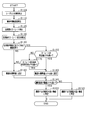
- FIG. 2 is a control flowchart executed by the detection ECU according to this embodiment.
- FIG. 3 is a control flowchart executed by a detection ECU according to another example.
- This driving support control functions as a PCS system (Pre-crash safety system) that performs control to avoid collision with an object or reduce collision damage.
- the driving support device 100 also functions as a crossing determination device according to the present embodiment.
- the driving support device 100 includes a detection ECU 10, a radar device 21, a yaw rate sensor (corresponding to a yaw rate detection unit) 22, and a steering angle sensor 23.
- the radar device 21 is, for example, a known millimeter wave radar that uses a high frequency signal in the millimeter wave band as a transmission wave.
- the radar device 21 is provided at the front end portion of the host vehicle and can detect an area within a predetermined detection angle. The position of the object within the detection range is detected. Specifically, an exploration wave is transmitted at a predetermined period, and a reflected wave is received by a plurality of antennas. The distance to the object is calculated from the transmission time of the exploration wave and the reception time of the reflected wave. Further, the relative speed (specifically, the relative speed in the traveling direction of the vehicle) is calculated from the frequency of the reflected wave reflected by the object, which has changed due to the Doppler effect.
- the azimuth of the object is calculated from the phase difference of the reflected waves received by the plurality of antennas. If the position and orientation of the object can be calculated, the relative position (lateral position) of the object with respect to the host vehicle can be specified. Therefore, the radar device 21 corresponds to an object detection unit and a crossing speed calculation unit. The radar device 21 performs transmission of the exploration wave, reception of the reflected wave, calculation of the reflection position and relative velocity at predetermined intervals, and transmits the calculated reflection position and relative velocity to the detection ECU 10.
- the radar device 21 is connected to the detection ECU 10.
- the detection ECU 10 is a computer that includes a CPU 11, a RAM 12, a ROM 13, an I / O, and the like.
- the detection ECU 10 realizes each function by the CPU 11 executing a program installed in the ROM 13.
- the program installed in the ROM 13 detects an object existing in front of the host vehicle based on information on the object detected by the radar device 21 (such as a calculated position and a relative speed), and performs a prescribed process. It is a control program for performing a driving support process.
- the detection ECU 10 corresponds to a yaw rate change rate calculation unit and a crossing determination unit.
- the driving support process corresponds to an alarm process for notifying the driver that there is an object that may collide with the host vehicle and a braking process for braking the host vehicle. Therefore, the host vehicle is provided with an alarm device 31 and a brake device 32 as a safety device that is driven by a control command from the detection ECU 10.
- the alarm device 31 is a speaker or a display installed in the passenger compartment of the host vehicle.
- the detection ECU 10 has a shorter time to collision (TTC: Time-to-Collision), which is the time it takes for the host vehicle to collide with the target, to reduce the possibility that the host vehicle will collide with an object. If it is determined that the alarm has occurred, the alarm device 31 outputs an alarm sound, an alarm message, or the like according to the control command from the detection ECU 10 to notify the driver of the risk of collision.
- TTC Time-to-Collision
- the brake device 32 is a braking device that brakes the host vehicle. If the detection ECU 10 determines that the collision margin time is shorter than the second predetermined time set to be shorter than the first predetermined time and the possibility that the own vehicle collides with the object has increased, the control from the detection ECU 10 The brake device 32 is actuated by the command. Specifically, the braking force with respect to the brake operation by the driver is increased (brake assist function), or automatic braking is performed if the brake operation is not performed by the driver (automatic brake function).
- crossing determination whether or not an object moving in a direction intersecting with the path of the host vehicle crosses the path of the host vehicle (hereinafter referred to as crossing determination) has been performed based on the amount of movement of the object. .
- This crossing determination can be performed based on the speed of the object in the direction crossing the path of the host vehicle (hereinafter referred to as the crossing speed) instead of the amount of movement of the object.
- the travel support apparatus 100 includes the yaw rate sensor 22 and the steering angle sensor 23.
- the yaw rate sensor 22 detects the angular velocity (yaw rate) in the turning direction of the vehicle
- the steering angle sensor 23 detects the steering angle of the host vehicle
- each sensor transmits the detected yaw rate and steering angle to the detection ECU 10.
- the detection ECU 10 can determine based on the received steering angle information and the position information of the object detected by the radar device 21 that the vehicle has changed its course in a direction approaching the object. If it is determined that the vehicle has changed its course in the direction of approaching the object, there is a risk that the crossing speed of the object will be excessively calculated based on the magnitude of the yaw rate generated by the vehicle changing the course. It can be determined whether or not there is.
- the detection ECU 10 A rate of change with time (hereinafter referred to as a yaw rate rate of change) is calculated.
- a rate of change with time hereinafter referred to as a yaw rate rate of change
- the object crossing determination with respect to the course of the host vehicle is performed based on the crossing speed of the object moving in the direction intersecting with the path of the host vehicle. Specifically, when the crossing speed of the object is higher than the threshold value, it is determined that the object crosses the course of the host vehicle. At this time, the threshold is set based on the crossing speed according to the type of object such as a pedestrian, a bicycle, a motorcycle, and an automobile. Instead of performing the crossing determination of the object based on the crossing speed of the object, the crossing determination of the object may be performed based on the movement amount of the object with time. Also, other examples described later can be applied as appropriate.
- the radar device 21 detects an object moving in a direction crossing the course of the host vehicle, and the detection ECU 10 changes the course from the steering angle sensor 23 in the direction in which the host vehicle approaches the object, and the yaw rate is set.
- the threshold used for the object crossing determination is reset higher than the standard value.
- the detection ECU 10 executes a crossing determination process shown in FIG.
- the crossing determination process shown in FIG. 2 is repeatedly executed at a predetermined cycle by the detection ECU 10 while the detection ECU 10 is powered on.
- step S100 the radar device 21 detects an object moving in a direction crossing the course of the host vehicle.
- step S110 the radar device 21 is caused to calculate the crossing speed of the object.
- step S120 the yaw rate sensor 22 detects the yaw rate of the host vehicle.
- step S130 the yaw rate change rate is calculated from the detected yaw rate of the host vehicle.
- step S140 based on the position information of the object detected by the radar device 21 and the information of the steering angle detected by the steering angle sensor 23, the host vehicle travels in a direction approaching the object detected by the radar device 21. It is determined whether or not it has been changed. If it is determined that the vehicle has not changed the course in the direction approaching the object (S140: NO), the process proceeds to step S180 described later. When the own vehicle changes the course in the direction approaching the object (S140: YES), the process proceeds to step S150.
- step S150 it is determined whether the yaw rate detected by the yaw rate sensor 22 is higher than a predetermined value.
- the process proceeds to step S160 described later.
- the process proceeds to step S170.
- step S170 it is determined whether or not the yaw rate change rate calculated in step S130 is higher than a predetermined change rate.
- the process proceeds to step S180.
- step S180 a threshold value used for object crossing determination is set to a standard value.
- the process proceeds to step S190.
- step S160 the threshold used for the object crossing determination is set higher than the standard value. And it progresses to below-mentioned step S190.
- step S190 it is determined whether or not the crossing speed of the object calculated in step S110 is higher than a threshold value. If it is determined that the crossing speed of the object is higher than the threshold (S190: YES), the process proceeds to step S200, where it is determined that there is a high possibility that the object crosses the course of the host vehicle, and this control is terminated. When it is determined that the crossing speed of the object is lower than the threshold (S190: NO), the process proceeds to step S210, where it is determined that the possibility that the object crosses the course of the host vehicle is low, and this control is terminated.
- this embodiment has the following effects.
- the threshold used for crossing determination is increased on the condition that the host vehicle is turning and running toward the object closer to the object and the yaw rate detected by the yaw rate sensor 22 is greater than the threshold. It is corrected as follows. Accordingly, it is possible to suppress erroneous determination to cross an object that does not cross the vehicle path even if the crossing speed of the object is excessively calculated.
- the threshold can be corrected to be high even in situations where the yaw rate is expected to be greater than a predetermined value in the future.
- the radar device 21 executes target detection.
- the imaging device 24 may detect a target.
- the imaging device 24 includes, for example, a monocular camera or a stereo camera using a CCD camera, a CMOS image sensor, a near infrared camera, or the like. Even in this case, since the position information and the relative speed of the target can be calculated based on the image captured by the imaging device 24, the same operations and effects as those of the above-described embodiment can be achieved by such a configuration.
- the threshold used for crossing determination is corrected to be high.
- the crossing speed of the object may be corrected while the threshold value is fixed.
- the threshold used for crossing determination remains fixed and the crossing speed of the object is reduced. It may be corrected.
- the yaw rate of the host vehicle when the yaw rate of the host vehicle is lower than a predetermined value, it is further determined whether or not the yaw rate change rate is higher than the predetermined change rate. It is not always necessary to determine whether or not the yaw rate change rate is higher than the predetermined change rate.
- whether or not the host vehicle has changed the course in a direction approaching the object detected by the radar device 21 is detected by the position information of the object detected by the radar device 21 and the steering angle sensor 23. Based on the information on the steering angle. Regarding this, it is not always necessary to use information on the steering angle detected by the steering angle sensor 23. For example, the turning angle with respect to the traveling direction of the own vehicle is calculated from the yaw rate of the own vehicle detected by the yaw rate sensor 22, and it is determined whether or not the course has been changed in the direction in which the own vehicle approaches the object based on the calculated turning angle. May be.
- the threshold used for the crossing determination is set to a standard value.
- the threshold used for the crossing determination is set lower than the standard value. May be.
- FIG. 3 is a modification of a part of the flowchart of FIG. That is, if NO is determined in step S340, which is the same process as step S140 in FIG. 2, the process proceeds to step S420, which is a new step.
- Step S420 is processing according to step S350 which is the same processing as step S150 in FIG. Specifically, it is determined whether the yaw rate of the host vehicle is higher than a predetermined value. If it is determined that the yaw rate of the host vehicle is higher than the predetermined value (S420: YES), the process proceeds to a later-described step S430, which is a new step.
- step S440 is processing according to step S370 which is the same processing as step S170 in FIG. Specifically, it is determined whether the yaw rate change rate is higher than a predetermined change rate. If it is determined that the yaw rate change rate is lower than the predetermined change rate (S440: NO), the process proceeds to step S380, which is the same process as step S180 in FIG. If it is determined that the yaw rate change rate is higher than the predetermined change (S440: YES), the process proceeds to step S430. In step S430, the threshold used for crossing determination is set lower than the standard value. And it progresses to step S390 which is the same process as step S190 in FIG.
- steps S300, 310, 320, 330, 360, 400, and 410 in FIG. 3 are respectively performed in steps S100, 110, 120, 130, 160, 200, and 210 in FIG. It is the same as the process.
- the threshold used for the crossing determination is set to be higher than the standard value. Set low. As a result, it is possible to suppress erroneous determination that an object that crosses the vehicle path is not crossed.
Landscapes
- Engineering & Computer Science (AREA)
- Automation & Control Theory (AREA)
- Transportation (AREA)
- Mechanical Engineering (AREA)
- Physics & Mathematics (AREA)
- General Physics & Mathematics (AREA)
- Human Computer Interaction (AREA)
- Mathematical Physics (AREA)
- Multimedia (AREA)
- Theoretical Computer Science (AREA)
- Traffic Control Systems (AREA)
- Control Of Driving Devices And Active Controlling Of Vehicle (AREA)
Abstract
自車両の進路に対して交差する方向に移動する物体を検出する物体検出部(21,24)と、自車両の現在の進路に対して、物体検出部により検出された物体が横断する速度である横断速度を算出する横断速度算出部(21,24)と、横断速度算出部により算出された横断速度が所定速度よりも高いことで、物体が自車両の進路を横断することを判定する横断判定部(10)と、自車両のヨーレートを検出するヨーレート検出部(22)と、を備え、横断判定部は、ヨーレート検出部により検出されたヨーレートに基づいて、物体の横断速度又は所定速度を補正することを特徴とする横断判定装置。
Description
本出願は、2016年3月7日に出願された日本出願番号2016-043625号に基づくもので、ここにその記載内容を援用する。
本開示は、車両に搭載され、車両の進路を物体が横断するか否かの判定を行う横断判定装置に関する。
近年、センサやデータ処理の高度化に伴って、自車両の進路に向かって横方向から物体が進入することで生じる衝突事故を未然に回避する走行支援装置を車両に搭載することが行われつつある。この走行支援装置として、運転者に警報したり、自動ブレーキを実施させたりするPCSシステム(Pre-crash safety system)が知られている。
特許文献1では、自車両の進路を横断する方向の物体の移動量に基づいて、物体が自車両の前方を横断しようとしているか否かを判定する。これにより、自車両の前方を横断しようとしている物体だけを対象に衝突可能性を判定することができる。
しかしながら、特許文献1に記載の技術では、例えば自車両の現在の進路に対して物体に近づく側へ自車両が曲がる場合、自車両の進路を横断する方向の物体の相対的な移動量が大きくなり、これにより物体の移動量を過大に演算するおそれがある。この場合、横断しない物体を横断するおそれがある物体として誤判定するおそれがある。
本開示は、上記課題を解決するためになされたものであり、その主たる目的は、自車両の走行が自車両の進路に対して横断する方向の物体の検出状態に影響を与える場面において、物体の横断判定の誤判定を抑制する事が可能な横断判定装置を提供することにある。
本開示は、横断判定装置であって、自車両の進路に対して交差する方向に移動する物体を検出する物体検出部と、前記自車両の現在の進路に対して、前記物体検出部により検出された前記物体が横断する速度である横断速度を算出する横断速度算出部と、前記横断速度算出部により算出された前記横断速度が所定速度よりも高いことで、前記物体が前記自車両の進路を横断することを判定する横断判定部と、前記自車両のヨーレートを検出するヨーレート検出部と、を備え、前記横断判定部は、前記ヨーレート検出部により検出された前記ヨーレートに基づいて、前記物体の前記横断速度又は前記所定速度を補正する。
自車両の進路に対して交差する方向に移動する物体が存在し、且つ、自車両が物体に近づく方向に向かって曲がったり、自車両が物体から離れる方向に向かって曲がったりする場合を想定する。この場合、自車両と物体との横位置方向における相対速度に変化が生じるため、自車両の現在の進路に対して物体が横断する横断速度に誤差が生じるおそれがある。したがって、ヨーレート検出部により検出された自車両のヨーレートに基づいて、横断判定部により物体の横断速度又は所定速度が補正される。これにより、自車両の走行が自車両の現在の進路に対して横断する方向の物体の横断速度の検出に影響を与える場面において、算出された物体の横断速度に誤差が生じても物体の横断判定の誤判定を抑制する事が可能となる。
本開示についての上記目的およびその他の目的、特徴や利点は、添付の図面を参照しながら下記の詳細な記述により、より明確になる。その図面は、
図1は、本実施形態に係る走行支援装置の概略構成図であり、
図2は、本実施形態に係る検出ECUが実施する制御フローチャートであり、
図3は、別例に係る検出ECUが実施する制御フローチャートである。
図1に記載の走行支援装置100は、車両(自車両)に搭載され、自車両の進行方向前方等の周囲に存在する物体を検知し、走行支援制御を実施する。この走行支援制御は、物体との衝突を回避すべく、若しくは衝突被害を軽減すべく制御を行うPCSシステム(Pre-crash safety system)として機能する。また、この走行支援装置100は、本実施形態に係る横断判定装置としても機能する。
走行支援装置100は、検出ECU10とレーダ装置21とヨーレートセンサ(ヨーレート検出部に該当)22と操舵角センサ23とから構成されている。
レーダ装置21は、例えば、ミリ波帯の高周波信号を送信波とする公知のミリ波レーダであり、自車両の前端部に設けられ、所定の検知角に入る領域を物体を検知可能な検知範囲とし、検知範囲内の物体の位置を検出する。具体的には、所定周期で探査波を送信し、複数のアンテナにより反射波を受信する。この探査波の送信時刻と反射波の受信時刻とにより、物体との距離を算出する。また、物体に反射された反射波の、ドップラー効果により変化した周波数により、相対速度(詳しくは車両の進行方向における相対速度)を算出する。加えて、複数のアンテナが受信した反射波の位相差により、物体の方位を算出する。なお、物体の位置及び方位が算出できれば、その物体の、自車両に対する相対位置(横位置)を特定することができる。よって、レーダ装置21は、物体検出部及び横断速度算出部に該当する。レーダ装置21は、所定周期毎に、探査波の送信、反射波の受信、反射位置及び相対速度の算出を行い、算出した反射位置と相対速度とを検出ECU10に送信する。
検出ECU10には、レーダ装置21が接続されている。検出ECU10は、CPU11、RAM12、ROM13、I/O等を備えたコンピュータである。この検出ECU10は、CPU11が、ROM13にインストールされているプログラムを実施することで各機能を実現する。本実施形態において、ROM13にインストールされているプログラムは、レーダ装置21が検出した物体の情報(算出した位置と相対速度など)に基づいて、自車両の前方に存在する物体を検出して規定の走行支援処理を実施させるための制御プログラムである。この検出ECU10は、ヨーレート変化率算出部及び横断判定部に該当する。
本実施形態において、走行支援処理とは、自車両と衝突するおそれのある物体が存在することをドライバに報知する警報処理と自車両を制動させる制動処理に該当する。したがって、自車両には、検出ECU10からの制御指令により駆動する安全装置として、警報装置31及びブレーキ装置32が備えられている。
警報装置31は、自車両の車室内に設置されたスピーカやディスプレイである。検出ECU10が、自車両が物標と衝突するまでの余裕時間である衝突余裕時間(TTC:Time-to-collision)が第一所定時間よりも縮まり、物体に自車両が衝突する可能性が高まったと判定した場合には、その検出ECU10からの制御指令により、警報装置31は警報音や警報メッセージ等を出力してドライバに衝突の危険を報知する。
ブレーキ装置32は、自車両を制動する制動装置である。検出ECU10が、衝突余裕時間が第一所定時間よりも短く設定された第二所定時間よりも縮まり、物体に自車両が衝突する可能性が高まったと判定した場合には、その検出ECU10からの制御指令により、ブレーキ装置32が作動する。具体的には、ドライバによるブレーキ操作に対する制動力をより強くしたり(ブレーキアシスト機能)、ドライバによりブレーキ操作が行われてなければ自動制動を行ったりする(自動ブレーキ機能)。
従来、自車両の進路に対して交差する方向に移動する物体が自車両の進路を横断するか否かの判定(以下、横断判定と呼称)は、物体の移動量に基づいて行われていた。この横断判定は、物体の移動量に代えて、自車両の進路を横断する方向の物体の速度(以下、横断速度と呼称)に基づいて行うこともできる。
ところで、自車両の現在の進路に対して物体に近づく側へ自車両が曲がる場合に、自車両の進路を横断する方向の物体の相対的な移動量が大きくなり、これにより物体の移動量を過大に演算するおそれがある。これは、物体の横断速度も同様であり、物体の横断速度もまた過大に演算されるおそれがある。よって、上記状況では、物体の移動量又は横断速度に基づいて横断判定を行うと、自車両の進路を横断しない物体を横断する物体として誤判定するおそれがある。
よって、本実施形態に係る走行支援装置100は、ヨーレートセンサ22及び操舵角センサ23を備えている。ヨーレートセンサ22は車両の旋回方向への角速度(ヨーレート)を検出し、操舵角センサ23は自車両の操舵角を検出し、それぞれのセンサは検出したヨーレートと操舵角とを検出ECU10に送信する。
検出ECU10は、受信した操舵角の情報とレーダ装置21により検出された物体の位置情報とに基づいて、自車両が物体に近づく方向に進路を変更したことを判定することができる。そして、自車両が物体に近づく方向に進路を変更したと判定した場合に、自車両が進路を変更することで生じたヨーレートの大きさに基づいて、物体の横断速度を過大に演算するおそれがあるか否かを判定できる。また、自車両が曲がり始める時など、将来的に物体の移動量又は横断速度が過大に演算されることが想定されながらもヨーレートが低く検出される状況を考慮し、検出ECU10は受信したヨーレートの時間経過に伴う変化率(以下、ヨーレート変化率と呼称)を算出する。ヨーレート変化率が所定変化率よりも大きくなることで、物体の移動量又は横断速度を過大に演算するおそれがあることを判定することができる。
本実施形態において、自車両の進路に対しての物体の横断判定は、自車両の進路に対して交差する方向に移動する物体の横断速度に基づいて行われる。具体的には、物体の横断速度が閾値よりも高い場合に、物体は自車両の進路を横断するものと判定する。このとき、閾値は、歩行者、自転車、自動二輪車、自動四輪車等、物体の種類に応じた横断速度に基づいて設定する。なお、物体の横断速度に基づいて物体の横断判定を行う代わりに、物体の時間経過に伴う移動量に基づいて物体の横断判定を行ってもよい。また、後述の別例を適宜適用することも可能である。
このとき、レーダ装置21により自車両の進路に対して交差する方向に移動する物体を検出しており、検出ECU10が操舵角センサ23から自車両が物体に近づく方向に進路を変更し、ヨーレートに基づいて物体の横断速度を過大に演算するおそれがあると判定した場合を想定する。この場合、物体の横断判定に用いる閾値を標準値よりも高く設定し直す。これにより、物体の横断速度が過大に演算されても、物体が車両の進路を横断すると誤判定することを抑制することができる。
本実施形態では、検出ECU10により後述する図2の横断判定処理を実行する。図2に示す横断判定処理は、検出ECU10が電源オンしている期間中に検出ECU10によって所定周期で繰り返し実行される。
まずステップS100にて、レーダ装置21により自車両の進路に対して交差する方向に移動する物体を検出させる。そして、ステップS110にて、レーダ装置21に物体の横断速度を算出させる。
また、ステップS120にて、ヨーレートセンサ22により自車両のヨーレートを検出させる。そして、ステップS130にて、検出された自車両のヨーレートからヨーレート変化率を算出する。
ステップS140では、レーダ装置21により検出された物体の位置情報と操舵角センサ23により検出された操舵角の情報とに基づいて、レーダ装置21により検出された物体に近づく方向に自車両が進路を変更したか否かを判定する。物体に近づく方向に自車両が進路を変更していないと判定した場合には(S140:NO)、後述のステップS180に進む。物体に近づく方向に自車両が進路を変更した場合には(S140:YES)、ステップS150に進む。
ステップS150では、ヨーレートセンサ22により検出されたヨーレートが所定値よりも高いか否かを判定する。ヨーレートが所定値よりも高いと判定した場合には(S150:YES)、後述のステップS160に進む。ヨーレートが所定値よりも低いと判定した場合には(S150:NO)、ステップS170に進む。
ステップS170では、ステップS130にて算出されたヨーレート変化率が所定変化率よりも高いか否かを判定する。ヨーレート変化率が所定変化率よりも低いと判定した場合には(S170:NO)、ステップS180に進む。ステップS180では、物体の横断判定に用いる閾値を標準値に設定する。そして、ステップS190に進む。ヨーレート変化率が所定変化率よりも高いと判定した場合には(S170:YES)、ステップS160に進む。ステップS160では、物体の横断判定に用いる閾値を標準値よりも高く設定する。そして、後述のステップS190に進む。
ステップS190では、ステップS110で算出させた物体の横断速度が閾値よりも高いか否かを判定する。物体の横断速度が閾値よりも高いと判定した場合には(S190:YES)、ステップS200に進み、物体が自車両の進路を横断する可能性が高いと判定し、本制御を終了する。物体の横断速度が閾値よりも低いと判定した場合には(S190:NO)、ステップS210に進み、物体が自車両の進路を横断する可能性が低いと判定し、本制御を終了する。
上記構成により、本実施形態は、以下の効果を奏する。
・現在の進路に対して物体に近づく側へ自車両が旋回して走行しており、且つヨーレートセンサ22により検出されたヨーレートが閾値よりも大きいことを条件として、横断判定に用いる閾値が高くなるように補正される。これにより、物体の横断速度が過大に算出されても車両の進路を横断しない物体を横断すると誤判定することを抑制する事ができる。
・ヨーレートの時間変化率を算出することで、一定期間における自車両の旋回角度の変化を考慮することができる。このため、自車両の曲がり始めなど現在はヨーレートが低く検出されるが、将来的にヨーレートが所定値よりも大きくなることが想定される状況でも、閾値を高く補正することができる。
上記実施形態を、以下のように変更して実行することもできる。
・上記実施形態では、レーダ装置21が物標の検出を実行していた。このことについて、レーダ装置21に限る必要はなく、例えば、撮像装置24が物標を検出してもよい。撮像装置24は、例えばCCDカメラ、CMOSイメージセンサ、近赤外線カメラ等を用いた単眼カメラやステレオカメラ等が含まれる。この場合でも、撮像装置24が撮影された画像に基づいて物標の位置情報や相対速度を算出することができるため、かかる構成によっても、上記実施形態と同様の作用・効果が奏される。
・上記実施形態において、物体の近づく方向に自車両が旋回し、物体の横断速度が過大に算出されるおそれのある状況では、横断判定に用いる閾値を高く補正していた。このことについて、必ずしも横断判定に用いる閾値を補正する必要はなく、例えば、閾値は固定のまま、物体の横断速度を補正してもよい。具体的には、物体の近づく方向に自車両が旋回し、物体の横断速度が過大に算出されることが想定される状況では、横断判定に用いる閾値は固定のまま、物体の横断速度を低く補正してもよい。
・上記実施形態では、自車両のヨーレートが所定値よりも低い場合に、更にヨーレート変化率が所定変化率よりも高いか否かの判定をしていた。このヨーレート変化率が所定変化率よりも高いか否かの判定は必ずしも実施する必要はない。
・上記実施形態では、レーダ装置21により検出された物体に近づく方向に自車両が進路を変更したか否かの判定は、レーダ装置21により検出された物体の位置情報と操舵角センサ23により検出された操舵角の情報とに基づいて実施されていた。このことについて、必ずしも操舵角センサ23により検出された操舵角の情報を用いる必要はない。例えば、ヨーレートセンサ22により検出された自車両のヨーレートから自車両の進行方向に対する回頭角を算出し、算出した回頭角に基づいて自車両が物体に近づく方向に進路を変更したか否かを判定してもよい。
・上記実施形態では、レーダ装置21により検出された物体の位置情報と操舵角センサ23により検出された操舵角の情報とに基づいて、物体に近づく方向に自車両が進路を変更していないと判定した場合には、横断判定に用いる閾値を標準値に設定していた。このことについて、自車両の現在の進路に対して物体が遠ざかる側へ自車両が曲がる場合、自車両の進路を横断する方向の物体の相対的な速度が小さくなり、これに伴い物体の横断速度を過小に演算するおそれがある。この場合に備え、自車両の現在の進路に対して物体が遠ざかる側へ自車両が曲がっており、且つ、ヨーレートが閾値よりも大きい場合に、横断判定に用いる閾値を標準値よりも低く設定してもよい。
図3は、図2のフローチャートの一部を変容したものである。すなわち、図2におけるステップS140と同一の処理であるステップS340においてNO判定となった場合に、新規ステップであるステップS420に進む。ステップS420は、図2におけるステップS150と同一の処理であるステップS350に準じる処理である。具体的には、自車両のヨーレートが所定値よりも高いか否かを判定する。自車両のヨーレートが所定値よりも高いと判定した場合には(S420:YES)、新規ステップである後述のステップS430に進む。自車両のヨーレートが所定値よりも低いと判定した場合には(S420:NO)、新規ステップであるステップS440に進む。ステップS440は、図2におけるステップS170と同一の処理であるステップS370に準じる処理である。具体的には、ヨーレート変化率が所定変化率よりも高いか否かを判定する。ヨーレート変化率が所定変化率よりも低いと判定した場合には(S440:NO)、図2におけるステップS180と同一の処理であるステップS380に進む。ヨーレート変化率が所定変化よりも高いと判定した場合には(S440:YES)、ステップS430に進む。ステップS430では、横断判定に用いる閾値を標準値よりも低く設定する。そして、図2におけるステップS190と同一の処理であるステップS390に進む。
それ以外のステップについて、図3の各ステップS300,310,320,330,360,400,及び410の処理は、それぞれ、図2の各ステップS100,110,120,130,160,200,及び210の処理と同一である。
本別例に係る制御を実施することで、自車両が物体から遠ざかる側に曲がり、物体の横断速度を過小に演算されることが想定される状況では、横断判定に用いる閾値を標準値よりも低く設定する。これにより、車両の進路を横断する物体を横断しないと誤判定することを抑制する事が可能となる。
本開示は、実施例に準拠して記述されたが、本開示は当該実施例や構造に限定されるものではないと理解される。本開示は、様々な変形例や均等範囲内の変形をも包含する。加えて、様々な組み合わせや形態、さらには、それらに一要素のみ、それ以上、あるいはそれ以下、を含む他の組み合わせや形態をも、本開示の範疇や思想範囲に入るものである。
Claims (7)
- 自車両の進路に対して交差する方向に移動する物体を検出する物体検出部(21,24)と、
前記自車両の現在の進路に対して、前記物体検出部により検出された前記物体が横断する速度である横断速度を算出する横断速度算出部(21,24)と、
前記横断速度算出部により算出された前記横断速度が所定速度よりも高いことで、前記物体が前記自車両の進路を横断することを判定する横断判定部(10)と、
前記自車両のヨーレートを検出するヨーレート検出部(22)と、
を備え、
前記横断判定部は、前記ヨーレート検出部により検出された前記ヨーレートに基づいて、前記物体の前記横断速度又は前記所定速度を補正する横断判定装置。 - 前記横断判定部は、前記現在の進路に対して前記自車両が前記物体に近付く側へ旋回しており、且つ前記ヨーレート検出部により検出された前記ヨーレートが所定値よりも大きいことを条件として、前記横断速度又は前記所定速度を前記物体の横断判定の成立が困難な方向に補正する請求項1に記載の横断判定装置。
- 前記ヨーレート検出部により検出された前記ヨーレートの時間変化率を算出するヨーレート変化率算出部(10)を備え、
前記横断判定部は、前記ヨーレート検出部により検出された前記ヨーレートと、前記ヨーレート変化率算出部により算出された前記時間変化率とに基づいて前記物体の速度又は前記所定速度を補正する請求項1又は2に記載の横断判定装置。 - 前記ヨーレート検出部により検出された前記ヨーレートの時間変化率を算出するヨーレート変化率算出部(10)を備え、
前記横断判定部は、前記現在の進路に対して前記自車両が前記物体に近付く側へ旋回しており、且つ、前記ヨーレート変化率算出部により算出された前記時間変化率が所定変化率よりも大きいことを条件として、前記横断速度又は前記所定速度を前記物体の横断判定の成立が困難な方向に補正する請求項1乃至3のいずれか1項に記載の横断判定装置。 - 自車両の進路に対して交差する方向に移動する物体を検出する物体検出部(21,24)と、
所定時間が経過したことで前記自車両の現在の進路に対して横断する方向に移動した前記物体検出部により検出された前記物体の移動量を算出する移動量算出部(10)と、
前記移動量算出部により算出された前記物体の移動量が所定移動量よりも多いことで、前記物体が前記自車両の進路を横断することを判定する横断判定部(10)と、
前記自車両のヨーレートを検出するヨーレート検出部(22)と、
を備え、
前記横断判定部は、前記ヨーレート検出部により検出された前記ヨーレートに基づいて、前記物体の前記移動量又は前記所定移動量を補正する横断判定装置。 - 前記横断判定部は、前記現在の進路に対して前記自車両が前記物体に近付く側へ旋回しており、且つ前記ヨーレート検出部により検出された前記ヨーレートが所定値よりも大きいことを条件として、前記物体の前記移動量又は前記所定移動量を前記物体の横断判定の成立が困難な方向に補正する請求項5に記載の横断判定装置。
- 前記横断判定部は、前記自車両が前記物体から離れる方向に向かって曲がる場合、前記自車両が前記物体から離れる方向に向かって曲がらない場合に比べて、前記物体が前記自車両の進路を横断すると判定され易くする請求項1乃至6のいずれか1項に記載の横断判定装置。
Priority Applications (1)
| Application Number | Priority Date | Filing Date | Title |
|---|---|---|---|
| US16/082,377 US10850730B2 (en) | 2016-03-07 | 2017-02-13 | Crossing determination apparatus |
Applications Claiming Priority (2)
| Application Number | Priority Date | Filing Date | Title |
|---|---|---|---|
| JP2016-043625 | 2016-03-07 | ||
| JP2016043625A JP6462610B2 (ja) | 2016-03-07 | 2016-03-07 | 横断判定装置 |
Publications (1)
| Publication Number | Publication Date |
|---|---|
| WO2017154471A1 true WO2017154471A1 (ja) | 2017-09-14 |
Family
ID=59789389
Family Applications (1)
| Application Number | Title | Priority Date | Filing Date |
|---|---|---|---|
| PCT/JP2017/005189 Ceased WO2017154471A1 (ja) | 2016-03-07 | 2017-02-13 | 横断判定装置 |
Country Status (3)
| Country | Link |
|---|---|
| US (1) | US10850730B2 (ja) |
| JP (1) | JP6462610B2 (ja) |
| WO (1) | WO2017154471A1 (ja) |
Families Citing this family (2)
| Publication number | Priority date | Publication date | Assignee | Title |
|---|---|---|---|---|
| WO2021121581A1 (en) * | 2019-12-18 | 2021-06-24 | Volvo Truck Corporation | A method for providing a positive decision signal for a vehicle |
| JP7415846B2 (ja) | 2020-08-11 | 2024-01-17 | 株式会社デンソー | 物体検出装置および物体検出方法 |
Citations (2)
| Publication number | Priority date | Publication date | Assignee | Title |
|---|---|---|---|---|
| JP2000062553A (ja) * | 1998-08-19 | 2000-02-29 | Honda Motor Co Ltd | 車両の走行安全装置 |
| JP2014089505A (ja) * | 2012-10-29 | 2014-05-15 | Daimler Ag | 他車検出装置 |
Family Cites Families (6)
| Publication number | Priority date | Publication date | Assignee | Title |
|---|---|---|---|---|
| US6269307B1 (en) | 1998-08-06 | 2001-07-31 | Honda Giken Kogyo Kabushiki Kaisha | Travel safety system for vehicle |
| US7095336B2 (en) * | 2003-09-23 | 2006-08-22 | Optimus Corporation | System and method for providing pedestrian alerts |
| US7881868B2 (en) * | 2007-06-12 | 2011-02-01 | Palo Alto Research Center Incorporated | Dual assessment for early collision warning |
| EP2615596B1 (en) * | 2010-09-08 | 2024-10-30 | Toyota Jidosha Kabushiki Kaisha | Moving-object prediction device, virtual-mobile-object prediction device, program, mobile-object prediction method, and virtual-mobile-object prediction method |
| WO2012172632A1 (ja) * | 2011-06-13 | 2012-12-20 | トヨタ自動車株式会社 | 運転支援装置及び運転支援方法 |
| JP5905846B2 (ja) | 2013-03-29 | 2016-04-20 | 株式会社日本自動車部品総合研究所 | 横断判定装置およびプログラム |
-
2016
- 2016-03-07 JP JP2016043625A patent/JP6462610B2/ja active Active
-
2017
- 2017-02-13 US US16/082,377 patent/US10850730B2/en active Active
- 2017-02-13 WO PCT/JP2017/005189 patent/WO2017154471A1/ja not_active Ceased
Patent Citations (2)
| Publication number | Priority date | Publication date | Assignee | Title |
|---|---|---|---|---|
| JP2000062553A (ja) * | 1998-08-19 | 2000-02-29 | Honda Motor Co Ltd | 車両の走行安全装置 |
| JP2014089505A (ja) * | 2012-10-29 | 2014-05-15 | Daimler Ag | 他車検出装置 |
Also Published As
| Publication number | Publication date |
|---|---|
| JP2017162005A (ja) | 2017-09-14 |
| US10850730B2 (en) | 2020-12-01 |
| US20190061751A1 (en) | 2019-02-28 |
| JP6462610B2 (ja) | 2019-01-30 |
Similar Documents
| Publication | Publication Date | Title |
|---|---|---|
| US10967857B2 (en) | Driving support device and driving support method | |
| US11069241B2 (en) | Driving support device and driving support method | |
| JP6561584B2 (ja) | 車両制御装置、及び車両制御方法 | |
| JP6504078B2 (ja) | 衝突予測装置 | |
| JP6451623B2 (ja) | 走行支援装置 | |
| US9470790B2 (en) | Collision determination device and collision determination method | |
| US20150232073A1 (en) | Collision avoidance assistance device and collision avoidance assistance method | |
| WO2018074287A1 (ja) | 車両制御装置 | |
| WO2018056212A1 (ja) | 物体検知装置及び物体検知方法 | |
| JP6432538B2 (ja) | 衝突予測装置 | |
| CN108137007B (zh) | 车辆控制装置以及车辆控制方法 | |
| WO2017104773A1 (ja) | 移動体制御装置及び移動体制御方法 | |
| WO2017104387A1 (ja) | 物体検知装置及び物体検知方法 | |
| WO2017104503A1 (ja) | 移動体制御装置及び移動体制御方法 | |
| WO2019012995A1 (ja) | 走行支援装置 | |
| JP6432496B2 (ja) | 物体検出装置 | |
| JP2017111055A (ja) | 物体検出装置 | |
| JP6462610B2 (ja) | 横断判定装置 | |
| US12559091B2 (en) | Control device for controlling safety device in vehicle | |
| JP7265971B2 (ja) | 制御装置 | |
| JP7377054B2 (ja) | 制御装置 |
Legal Events
| Date | Code | Title | Description |
|---|---|---|---|
| NENP | Non-entry into the national phase |
Ref country code: DE |
|
| 121 | Ep: the epo has been informed by wipo that ep was designated in this application |
Ref document number: 17762814 Country of ref document: EP Kind code of ref document: A1 |
|
| 122 | Ep: pct application non-entry in european phase |
Ref document number: 17762814 Country of ref document: EP Kind code of ref document: A1 |