WO2017150647A1 - 照明装置固定部材 - Google Patents
照明装置固定部材 Download PDFInfo
- Publication number
- WO2017150647A1 WO2017150647A1 PCT/JP2017/008216 JP2017008216W WO2017150647A1 WO 2017150647 A1 WO2017150647 A1 WO 2017150647A1 JP 2017008216 W JP2017008216 W JP 2017008216W WO 2017150647 A1 WO2017150647 A1 WO 2017150647A1
- Authority
- WO
- WIPO (PCT)
- Prior art keywords
- anchor bolt
- lighting device
- device fixing
- fixing member
- shaped spring
- Prior art date
- Legal status (The legal status is an assumption and is not a legal conclusion. Google has not performed a legal analysis and makes no representation as to the accuracy of the status listed.)
- Ceased
Links
Images




Classifications
-
- F—MECHANICAL ENGINEERING; LIGHTING; HEATING; WEAPONS; BLASTING
- F16—ENGINEERING ELEMENTS AND UNITS; GENERAL MEASURES FOR PRODUCING AND MAINTAINING EFFECTIVE FUNCTIONING OF MACHINES OR INSTALLATIONS; THERMAL INSULATION IN GENERAL
- F16B—DEVICES FOR FASTENING OR SECURING CONSTRUCTIONAL ELEMENTS OR MACHINE PARTS TOGETHER, e.g. NAILS, BOLTS, CIRCLIPS, CLAMPS, CLIPS OR WEDGES; JOINTS OR JOINTING
- F16B1/00—Devices for securing together, or preventing relative movement between, constructional elements or machine parts
-
- F—MECHANICAL ENGINEERING; LIGHTING; HEATING; WEAPONS; BLASTING
- F21—LIGHTING
- F21S—NON-PORTABLE LIGHTING DEVICES; SYSTEMS THEREOF; VEHICLE LIGHTING DEVICES SPECIALLY ADAPTED FOR VEHICLE EXTERIORS
- F21S8/00—Lighting devices intended for fixed installation
- F21S8/04—Lighting devices intended for fixed installation intended only for mounting on a ceiling or the like overhead structures
-
- F—MECHANICAL ENGINEERING; LIGHTING; HEATING; WEAPONS; BLASTING
- F21—LIGHTING
- F21V—FUNCTIONAL FEATURES OR DETAILS OF LIGHTING DEVICES OR SYSTEMS THEREOF; STRUCTURAL COMBINATIONS OF LIGHTING DEVICES WITH OTHER ARTICLES, NOT OTHERWISE PROVIDED FOR
- F21V17/00—Fastening of component parts of lighting devices, e.g. shades, globes, refractors, reflectors, filters, screens, grids or protective cages
- F21V17/10—Fastening of component parts of lighting devices, e.g. shades, globes, refractors, reflectors, filters, screens, grids or protective cages characterised by specific fastening means or way of fastening
-
- F—MECHANICAL ENGINEERING; LIGHTING; HEATING; WEAPONS; BLASTING
- F21—LIGHTING
- F21V—FUNCTIONAL FEATURES OR DETAILS OF LIGHTING DEVICES OR SYSTEMS THEREOF; STRUCTURAL COMBINATIONS OF LIGHTING DEVICES WITH OTHER ARTICLES, NOT OTHERWISE PROVIDED FOR
- F21V21/00—Supporting, suspending, or attaching arrangements for lighting devices; Hand grips
-
- F—MECHANICAL ENGINEERING; LIGHTING; HEATING; WEAPONS; BLASTING
- F21—LIGHTING
- F21V—FUNCTIONAL FEATURES OR DETAILS OF LIGHTING DEVICES OR SYSTEMS THEREOF; STRUCTURAL COMBINATIONS OF LIGHTING DEVICES WITH OTHER ARTICLES, NOT OTHERWISE PROVIDED FOR
- F21V21/00—Supporting, suspending, or attaching arrangements for lighting devices; Hand grips
- F21V21/02—Wall, ceiling, or floor bases; Fixing pendants or arms to the bases
- F21V21/03—Ceiling bases, e.g. ceiling roses
Definitions
- the present invention relates to a lighting device fixing member for attaching a lighting device to an anchor bolt extending vertically downward from a building housing, and a lighting system using the same.
- LEDs light emitting diodes
- an illuminating device for example, an LED light source arranged linearly facing a side end surface of a plate-like light guide plate is arranged, light is incident on the light guide plate, and adjacent to the side end surface on which the light source is arranged.
- the conventional lighting device fixing member is usually about the same size as the opening provided on the ceiling surface, but on the other hand, the lighting device fixing member is reduced in weight and cost. There is a demand to plan.
- the anchor bolts are generally extended vertically downward from the building frame so that the distance between the anchor bolts (anchor bolt pitch) is 800 mm or 600 mm.
- the illuminating device fixing member to be used is provided with two mounting holes for inserting the anchor bolts. The distance between the holes is 800 mm.
- Such two mounting holes provided at intervals of 800 mm cannot be used when installing a lighting device on the ceiling surface of a building having an anchor bolt pitch of 600 mm, and the anchor bolt pitch is 600 mm.
- This invention is made
- the present invention provides a lighting device attached to an indoor ceiling surface using a plurality of anchor bolts extending vertically downward from a building housing.
- a lighting device fixing member that is installed in a pair near the provided opening, and is provided with an anchor bolt mounting hole through which one anchor bolt of the plurality of anchor bolts is inserted.
- a pair of left and right V-shaped spring mounting holes for latching a V-shaped spring provided in the lighting device are provided on the both sides of the base.
- the two The contact portion is the opening.
- Each two edge portions facing to provide an illumination device fixing member characterized in that the abutment (invention 1).
- the lighting device fixing member is almost as much as the opening provided on the ceiling surface as in the past. It is not necessary to have a size of. Therefore, the present inventors use two pairs of lighting device fixing members to suspend the lighting device, thereby reducing the size of each lighting device fixing member and reducing the manufacturing cost. I came up with a reduction.
- one lighting device fixing member having a pair of left and right V-shaped spring mounting holes is attached to one anchor bolt, and a set of four lighting devices in total is used.
- the contact portions on both sides of the lighting device fixing member contact the edge of the opening provided on the indoor ceiling surface. Since the abutment part can be fixed to the edge of the opening in a state, the weight of the lighting device can be stably adjusted in three places including not only the anchor bolt but also the edge of the opening of the indoor ceiling surface. Can support. Therefore, it is possible to reduce the manufacturing cost by reducing the size of each lighting device fixing member while maintaining the same mounting performance as in the past.
- the distance from the anchor bolt mounting hole to each of the pair of left and right V-shaped spring mounting holes is equal, and the anchor bolt mounting hole is each of the pair of left and right V-shaped spring mounting holes. It is preferable that they are offset without overlapping with the imaginary line connecting the centers (Invention 2).
- the distance from the anchor bolt mounting hole to each of the pair of left and right V-shaped spring mounting holes is equal. It means that the anchor bolt mounting hole is on the middle line on both sides of the base.
- the lighting device fixing member can be used even if it is rotated halfway (180 degrees) horizontally with respect to the ceiling surface. It is possible to easily cope with two anchor bolt pitches that differ by the amount.
- the perpendicular distance from the center of the said anchor bolt attachment hole to the virtual line which connected each center of the said left-right paired V-shaped spring attachment hole is 50 mm (invention 3).
- the case where the two lighting device fixing members are used facing each other is compared with the case where the two lighting device fixing members are used by being half-rotated horizontally with respect to the ceiling surface.
- the distance between the anchor bolt mounting holes of the two lighting device fixing members can be varied by a maximum of 200 mm, so that the anchor bolt pitch is 800 mm. Can also be used for 600 mm buildings.
- the contact portion is extended so as to protrude to the side where the anchor bolt mounting hole is located in the base (Invention 4).
- the V-shaped spring of the lighting device is hooked in the V-shaped spring mounting hole of the lighting device fixing member, and protrudes when a vertical downward load is applied to the lighting device fixing member. Since the abutting portion is on the opposite side of the V-shaped spring mounting hole with the anchor bolt mounting hole as the center, the protruding abutting portion is pressed against the edge of the opening, so that the mounting state of the lighting device is stable It can be.
- the present invention provides an illumination system in which one illumination device is attached to a ceiling surface using two illumination device fixing members according to any one of claims 1 to 4 (invention 5).
- the lighting device mounting member of the present invention can realize the weight reduction of the entire member and reduce the manufacturing cost while maintaining the same mounting performance as before. Moreover, it can respond to two different anchor bolt pitches although it is a structure that leads to weight reduction and cost reduction.
- FIG. 1 is a perspective view showing the structure of a lighting device fixing member 1 according to this embodiment
- FIG. 2 is a plan view.
- the illuminating device fixing member 1 includes a flat base 2 and contact portions 3 a and 3 b provided on opposite side sides 21 a and 21 b of the base 2.
- the lighting device fixing member 1 is manufactured by, for example, bender processing of a steel plate or roll forming of a rolled steel plate, but is not limited thereto, and may be made of an aluminum alloy manufactured by, for example, extrusion molding.
- the base portion 2 and the contact portions 3a and 3b are preferably formed integrally, but may be formed separately by means such as welding after being manufactured separately.
- the base portion 2 has a substantially rectangular flat plate shape in plan view, and a pair of left and right V-spring mounting holes 4a and 4b for engaging the V-shaped spring 40 provided in the light emitting unit 100 (illuminating device), and a construction.
- An anchor bolt mounting hole 5 through which an anchor bolt B extending vertically downward from the housing is inserted is formed.
- the V-shaped spring mounting holes 4a and 4b have a slightly elongated long hole shape, and are provided symmetrically along the opposite side sides 21a and 21b of the base 2 as shown in FIG. Further, the anchor bolt mounting hole 5 has a long hole shape close to an ellipse (long axis length 20 mm), and two sides (upper side 21c and lower side 21d) sandwiched between both sides 21a and 21b of the base 2. Is provided in the vicinity of the lower side 21d so as to be positioned on the middle line between the side sides 21a and 21b.
- the distance from the anchor bolt mounting hole 5 to the V-shaped spring mounting hole 4a and the anchor bolt mounting hole 5 to V The distance to the spring mounting hole 4b is equal, and the anchor bolt mounting hole 5 is offset without overlapping with the virtual line H connecting the centers of the pair of left and right V spring mounting holes 4a, 4b. It is the positional relationship.
- the perpendicular distance L that is, the offset width
- the anchor bolt mounting hole 5 to the virtual line H connecting the centers of the pair of left and right V-shaped spring mounting holes 4a and 4b is 50 mm. Yes.
- the abutting portions 3a and 3b are long members having an L-shaped cross section, and are extended symmetrically and in the same shape on opposite side sides 21a and 21b of the base portion 2. Specifically, the abutting portions 3a and 3b are formed such that the side wall portions 31a and 31b raised up perpendicularly to the base portion 2 and the end portions of the side wall portions 31a and 31b opposite to the base portion 2 face outward. It is comprised from the flange parts 32a and 32b bent and extended at right angle. Further, the contact portions 3a and 3b are extended so as to protrude toward the side where the anchor bolt mounting hole 5 is located in the base portion 2 (that is, the lower side 21d side of the base portion 2).
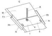
- the lighting device fixing member 1 is attached to an anchor bolt B as shown in FIG.
- the anchor bolt B is extended vertically downward from the building housing.
- an opening W is provided on the ceiling surface C at a position where two anchor bolts B can be seen.
- the side walls 31a and 31b can be fixed to the side wall of the opening W by fixing means such as screws, and the flanges 32a and 32b can be fixed to the ceiling surface C around the opening W by screws or the like. It can also be fixed by means.
- the light emitting unit 100 is installed on the ceiling surface C using two lighting device fixing members 1.
- the light emitting unit 100 is a so-called flat illuminating device, and includes a light emitting unit 10, an outer frame member 20, a reinforcing member 30, a V-shaped spring 40, and a power supply unit 50 as shown in FIG. .
- the light emitting unit 10 has a laminated structure of a light guide plate 11 and a reflection sheet 12, and a light source 13 is disposed at a side end of the light guide plate 11.
- the light guide plate 11 constituting the light emitting unit 10 is a flat plate having a rectangular shape in plan view, and has an outgoing light surface 111 on the lower flat plate surface in FIG.
- the light guide plate 11 is formed of a known transparent resin such as acrylic resin, and is subjected to reflection processing so that light incident on the side end surface from the light source 13 is emitted in a planar shape from the outgoing light surface 111.
- the reflection sheet 12 is laminated on the flat plate surface opposite to the outgoing light surface 111 of the light guide plate 11, that is, on the back side of the outgoing light surface 111.
- the reflection sheet 12 is formed from a thin aluminum plate or resin sheet having a thickness of about 0.5 mm, for example, and is laminated so as to cover the entire flat plate surface of the light guide plate 11.
- the light source 13 is formed by arranging a plurality of LEDs (not shown) at a predetermined interval on a long LED substrate (not shown), and is arranged to face one side end surface of the light guide plate 11. Yes.
- the outer frame member 20 is a frame member having a rectangular shape in a plan view in which the light emitting unit 10 is fitted so that the four sides surround the side end surface of the light guide plate 11 on which the reflection sheet 12 is laminated, and the light source 13 is accommodated inside the outer frame member 20. Is done.
- the outer frame member 20 is manufactured by, for example, bender processing of a steel plate or roll forming of a rolled steel plate, but is not limited thereto, and may be made of an aluminum alloy manufactured by, for example, extrusion molding.
- the reinforcing member 30 is an elongated member having an elongated flat plate shape, and is disposed so as to extend over two opposing long sides of the outer frame member 20, and both end portions are formed on the two opposing long sides of the outer frame member 20. It is fixed.
- the reinforcing member 30 is manufactured by, for example, bender processing of a steel plate or roll forming of a rolled steel plate, but is not limited thereto, and may be made of, for example, an aluminum alloy manufactured by extrusion molding. Good.
- the outer frame member 20 is provided with a total of four V-shaped springs 40 for detachably attaching the light emitting unit 100 to the two lighting device fixing members 1 attached to the openings W provided on the ceiling surface C. It has been. Specifically, two V-shaped springs 40 are provided symmetrically on two opposing long sides of the outer frame member 20, and the two V-shaped springs 40 on each long side are separated by 700 mm. Has been placed.
- the V-shaped spring 40 is formed by bending a single metal wire into a V-shape. As shown in FIG. 6, a winding portion 41 in which the metal wire is coiled a plurality of times, and both ends of the winding portion 41. A pair of arm portions 42 extending from the arm portion 42, and an arm end 43 formed by bending each distal end portion of the arm portion 42 in a bowl shape. The arm end 43 is provided so as to protrude in the outward direction of the V shape of the pair of arm portions 42.
- the V-shaped spring 40 is attached to the outer frame member 20 so that the attachment claws 201 provided in the outer frame member 20 are passed through the winding portion 41.
- the power supply unit 50 is connected to a power cable (not shown) in the opening W, converts an AC (alternating current) voltage into a DC voltage to drive the LED with a DC (direct current) voltage, and supplies power to the light emitting unit 10. It is for delivery.
- a state in which one light emitting unit 100 is installed on the ceiling surface C using two lighting device fixing members 1 will be described with reference to FIG.
- the lighting device fixing member 1 according to the present embodiment, even when the light emitting unit 100 is installed on the ceiling surface of a building having an anchor bolt pitch of 800 mm, the ceiling of the building having an anchor bolt pitch of 600 mm. It is possible to cope with the case where the light emitting unit 100 is installed on the surface.
- the conventional lighting device fixing member has a size almost the same as the opening W provided on the ceiling surface C, and the anchor bolt pitch is 800 mm.
- the anchor bolt pitch is 800 mm.
- one lighting device fixing member according to this embodiment (hereinafter, the left side is expressed as 1L and the right side is expressed as 1R).
- Each of the abutting portions 3a and 3b is attached to the two anchor bolts B so as to protrude outward.
- the perpendicular distance L from the anchor bolt mounting hole 5 of the lighting device fixing member 1 to the virtual line H connecting the centers of the pair of left and right V-shaped spring mounting holes 4a and 4b is 50 mm.
- the right lighting device fixing member 1R is connected to the right illuminating device fixing member 1R from the virtual line H connecting the centers of the V-shaped spring mounting holes 4a and 4b of the left lighting device fixing member 1L.
- the distance to the virtual line H connecting the centers of the V-shaped spring mounting holes 4a and 4b is 700 mm. Since the two V-shaped springs 40 on the respective long sides of the light emitting unit 100 are arranged at a distance of 700 mm, the four V-shaped springs 40 of the light emitting unit 100 are respectively connected to the two lighting device fixing members 1L and 1R. It can be hooked into the letter spring mounting holes 4a, 4b.
- the contact portions 3a and 3b project the two lighting device fixing members 1L and 1R inwardly, respectively. Are attached to the two anchor bolts B, respectively. If the two lighting device fixing members 1L, 1R are attached to the anchor bolt B in this manner, the right side of the imaginary line H connecting the centers of the V-shaped spring mounting holes 4a, 4b of the left lighting device fixing member 1L The distance to the imaginary line H connecting the centers of the V-shaped spring mounting holes 4a and 4b of the lighting device fixing member 1R is also 700 mm as in FIG. 7B.
- the four V-shaped springs 40 of the light emitting unit 100 are respectively connected to the two lighting device fixing members 1L and 1R. It can be hooked into the letter spring mounting holes 4a, 4b.
- the distance between the anchor bolt mounting holes 5 of the two lighting device fixing members 1L and 1R can be changed by a maximum of 200 mm. Can be used for 800 mm and 600 mm buildings. In addition, if only one of the two lighting device fixing members 1L and 1R is rotated halfway, it can be used for a building having an anchor bolt pitch of 700 mm. Further, since the anchor bolt mounting hole 5 is a long hole (long axis length: 20 mm), even if the anchor bolt pitch is slightly deviated during construction, the anchor bolt mounting hole 5 can cope with it.
- the contact portions 3a and 3b on both sides of the lighting device fixing member 1 are in contact with the edge of the opening W provided on the indoor ceiling surface C, and this state Since the contact portions 3a and 3b can be fixed to the edge of the opening W, the weight of the light emitting unit 100 is not limited to the anchor bolt B but the edge of the opening W of the indoor ceiling surface C. It can be stably supported at a total of three locations. Therefore, it is possible to reduce the manufacturing cost by reducing the size of each lighting device fixing member 1 while maintaining the same mounting performance as in the prior art.
- the contact portions 3a and 3b are extended so as to protrude to the side where the anchor bolt mounting hole 5 of the base portion 2 is located, and the protruding contact portions 3a and 3b are centered on the anchor bolt mounting hole 5.
- the V-shaped spring 40 of the light emitting unit 100 is hooked on the V-shaped spring mounting holes 4a, 4b of the lighting device fixing member 1, and the lighting device fixing member
- the protruding contact portions 3a and 3b are pressed against the edge of the opening W, so that the mounting state of the lighting device can be stabilized.
Landscapes
- Engineering & Computer Science (AREA)
- General Engineering & Computer Science (AREA)
- Mechanical Engineering (AREA)
- Non-Portable Lighting Devices Or Systems Thereof (AREA)
- Securing Globes, Refractors, Reflectors Or The Like (AREA)
- Planar Illumination Modules (AREA)
Abstract
照明装置固定部材(1)は、建造物躯体から鉛直下方向に延設された複数のアンカーボルトBを用いて照明装置(100)を室内天井面Cに取り付けるために、室内天井面Cに設けられた開口部W近傍に二つ一組で設置される。 照明装置固定部材(1)は、複数のアンカーボルトBのうちの一本のアンカーボルトBが挿通されるアンカーボルト取付孔(5)が設けられた平板状の基部(2)と、基部(2)の両側辺部に設けられた二つの当接部(3a)、(3b)とを備える。照明装置(100)に設けられたV字ばね(40)を掛止する左右一対のV字ばね取付孔(4a)、(4b)が基部(2)の両側辺部に沿って対称に設けられており、アンカーボルト取付孔(5)に一本のアンカーボルトBを挿通して照明装置固定部材(1)を一本のアンカーボルトBに固定したときに、二つの当接部(3a)、(3b)が開口部Wの対向する二つ の端縁部にそれぞれ当接する。
Description
本発明は、照明装置を建造物躯体から鉛直下方向に延設されたアンカーボルトに取り付けるための照明装置固定部材及びそれを用いた照明システムに関する。
近年、発光ダイオード(LED;Light Emitting Diode)等の発光素子を光源として用いる照明装置が普及している。そのような照明装置として、例えば板状の導光板の側端面に対向して線状に配列されたLED光源を配置して導光板内に光を入射し、光源の配置された側端面に隣接する二面の平板面のいずれかから光を外部に射出して面状に発光させる、平板形状の照明装置が知られている。
このような照明装置を天井に設置する場合、例えば特許文献1に開示されているように、天井に開口部を設け、電源等の収納される照明装置固定部材を開口部内のアンカーボルトに取り付け、その照明装置固定部材に設けられた取付金具に、照明装置(発光部ユニット)のフレーム部材上に配置されているV字ばねを引っ掛けて照明装置を照明装置固定部材に固定する構造が知られている。このような構造の場合、まずV字ばねの先端部をV字が閉じるように握って先端部のみを取付金具に引っ掛けて仮固定状態とし、この状態で照明装置と天井面との間から手を伸ばして照明装置と電源とを繋ぐ配線作業等を行い、作業完了後に照明装置を押し上げるとV字ばねの付勢力によって照明装置が天井面に固定される。
天井面に照明装置を設ける際には、照明装置が容易に落下することがないだけの十分な剛性や安定性といった取付性能を持った照明装置固定部材が求められる。そのため、従来の照明装置固定部材は天井面に設けられた開口部とほぼ同じくらいの大きさを有しているのが通常であるが、その一方で、照明装置固定部材の軽量化やコストダウンを図りたいという要求がある。
また、アンカーボルトは一般的にアンカーボルト間の間隔(アンカーボルトピッチ)が800mm又は600mmとなるように建造物躯体から鉛直下方向に延設されていることが多い。例えばアンカーボルトピッチが800mmである建造物の天井面に照明装置を設置する場合、使用する照明装置固定部材にはアンカーボルトを挿通させるための取付孔が二つ設けられており、この二つの取付孔間の距離が800mmとなっていることになる。このような800mm間隔で設けられた二つの取付孔を、アンカーボルトピッチが600mmである建造物の天井面に照明装置を設置するときに使用することは当然できず、アンカーボルトピッチが600mmである建造物の天井面に照明装置を設置する場合には、別途600mmのアンカーボルトピッチ対応の照明装置固定部材を用意しておくか、あるいはアンカーボルトピッチが800mmであっても600mmであっても対応できるように全部で四つの取付孔を設けておかなければならないという問題もある。
本発明は、このような点に鑑みてなされたものであり、軽量化及びコストダウンにつながる構造を有する照明装置固定部材を提供することを目的とする。また、軽量化及びコストダウンにつながる構造でありながら、異なる二つのアンカーボルトピッチに対応することが可能な構造を有する照明装置固定部材を提供することを目的とする。
上記目的を達成するために、第一に本発明は、建造物躯体から鉛直下方向に延設された複数のアンカーボルトを用いて照明装置を室内天井面に取り付けるために、前記室内天井面に設けられた開口部近傍に二つ一組で設置される照明装置固定部材であって、前記複数のアンカーボルトのうちの一本のアンカーボルトが挿通されるアンカーボルト取付孔が設けられた平板状の基部と、該基部の両側辺部に設けられた二つの当接部とを備え、前記照明装置に設けられたV字ばねを掛止する左右一対のV字ばね取付孔が前記基部の前記両側辺部に沿って対称に設けられており、前記アンカーボルト取付孔に前記一本のアンカーボルトを挿通して前記照明装置固定部材を前記一本のアンカーボルトに固定したときに、前記二つの当接部が前記開口部の対向する二つの端縁部にそれぞれ当接することを特徴とする照明装置固定部材を提供する(発明1)。
照明装置が容易に落下することがないだけの十分な剛性や安定性といった取付性能を維持できるのであれば、必ずしも従来のように照明装置固定部材を天井面に設けられた開口部とほぼ同じくらいの大きさとする必要はない。そこで本発明者らは、照明装置固定部材を二つ一組で用いて照明装置を吊持することで、それぞれの照明装置固定部材の大きさを小さくすることにより軽量化を図り、製造コストを低減することに想到した。上記発明(発明1)によれば、左右一対のV字ばね取付孔を有する一つの照明装置固定部材が一本のアンカーボルトに取り付けられ、これを二つ一組で用いて照明装置の合計四つのV字ばねを掛止して照明装置を室内天井面に設置する際に、照明装置固定部材の両側の当接部が室内天井面に設けられた開口部の端縁部に当接し、この状態で当接部を開口部の端縁部に固定することができるため、照明装置の重さをアンカーボルトのみならず室内天井面の開口部の端縁部を含む合計三箇所で安定的に支えることができる。そのため、従来同様の取付性能を維持したまま、それぞれの照明装置固定部材の大きさを小さくすることにより軽量化を図り、製造コストを低減することができる。
上記発明(発明1)においては、前記アンカーボルト取付孔から前記左右一対のV字ばね取付孔のそれぞれまでの距離が等しく、かつ前記アンカーボルト取付孔が前記左右一対のV字ばね取付孔のそれぞれの中心を結んだ仮想線と重ならずオフセットしていることが好ましい(発明2)。
左右一対のV字ばね取付孔が基部の両側辺部に沿って対称に設けられている場合に、アンカーボルト取付孔から左右一対のV字ばね取付孔のそれぞれまでの距離が等しいということは、アンカーボルト取付孔が基部の両側辺の中間線上にあるということを意味する。上記発明(発明2)によれば、照明装置固定部材を天井面に対して水平に半回転(180度回転)させても用いることができ、このように半回転させて用いることによりオフセット幅の分だけ異なる二つのアンカーボルトピッチに容易に対応することができる。
上記発明(発明2)においては、前記アンカーボルト取付孔の中心から前記左右一対のV字ばね取付孔のそれぞれの中心を結んだ仮想線までの垂線距離が50mmであることが好ましい(発明3)。
上記発明(発明3)によれば、二つの照明装置固定部材を正対させて用いる場合と、二つの照明装置固定部材をそれぞれ天井面に対して水平に半回転させて用いる場合とを比較すると、左右一対のV字ばね取付孔の位置を固定して考えると二つの照明装置固定部材のアンカーボルト取付孔間の距離を最大200mm変動させることができるため、アンカーボルトピッチが800mmの建造物にも600mmの建造物にも用いることができる。
上記発明(発明1~3)においては、前記当接部が、前記基部において前記アンカーボルト取付孔が位置している側に突出するように延伸されていることが好ましい(発明4)。
上記発明(発明4)によれば、照明装置のV字ばねを照明装置固定部材のV字ばね取付孔に掛止し、照明装置固定部材に鉛直下方向の荷重がかかった場合に、突出した当接部がアンカーボルト取付孔を中心にしてV字ばね取付孔の反対側にあるため、その突出した当接部が開口部端縁部に押し付けられるため、照明装置の取付状態を安定したものとすることができる。
第二に本発明は、請求項1~4のいずれか1項に記載の照明装置固定部材を二つ用いて一つの照明装置を天井面に取り付けた照明システムを提供する(発明5)。
本発明の照明装置取付部材は、従来同様の取付性能を維持しつつも部材全体の軽量化を実現し、かつ製造コストを下げることができるものとなっている。また、軽量化及びコストダウンにつながる構造でありながら、異なる二つのアンカーボルトピッチに対応することができる。
以下、本発明の実施形態を図面に基づいて詳細に説明する。図1は本実施形態に係る照明装置固定部材1の構造を示す斜視図であり、図2は平面図である。照明装置固定部材1は、平板状の基部2と、基部2の対向する両側辺21a、21bに設けられた当接部3a、3bとから構成されている。照明装置固定部材1は、例えば鋼板のベンダー加工やロール鋼板のロールフォーミングによって製造されるが、これに限られるものではなく、例えば押し出し成形によって製造されるアルミニウム合金製であってもよい。基部2と当接部3a、3bとは一体的に成形されていることが好ましいが、別々に製造された後に溶接等の手段で一体化されたものであってもよい。
基部2は平面視略矩形の平板形状を有しており、発光部ユニット100(照明装置)に設けられたV字ばね40を掛止する左右一対のV字ばね取付孔4a、4bと、建造物躯体から鉛直下方向に延設されたアンカーボルトBが挿通されるアンカーボルト取付孔5とが穿設されている。
V字ばね取付孔4a、4bはやや細長い長孔形状を有しており、図2に示すように、基部2の対向する両側辺21a、21bに沿って対称に設けられている。また、アンカーボルト取付孔5は楕円に近い長孔形状を有しており(長軸の長さ20mm)、基部2の両側辺21a、21bに挟まれた二つの辺(上辺21c及び下辺21d)のうちの下辺21dの近傍に、両側辺21a、21bの中間線上に位置するように設けられている。
上述のようにV字ばね取付孔4a、4b及びアンカーボルト取付孔5が設けられていることにより、アンカーボルト取付孔5からV字ばね取付孔4aまでの距離と、アンカーボルト取付孔5からV字ばね取付孔4bまでの距離が等しくなっており、かつアンカーボルト取付孔5が左右一対のV字ばね取付孔4a、4bのそれぞれの中心を結んだ仮想線Hと重ならずオフセットしているという位置関係になっている。また、本実施形態においては、アンカーボルト取付孔5から左右一対のV字ばね取付孔4a、4bのそれぞれの中心を結んだ仮想線Hまでの垂線距離L(すなわちオフセット幅)が50mmになっている。
当接部3a、3bは、断面L字形状の長尺部材であり、基部2の対向する両側辺21a、21bに対称かつ同一形状で延設されている。具体的には当接部3a、3bは、基部2に対して垂直に立ち上げられた側壁部31a、31bと、側壁部31a、31bの基部2とは逆側の端部を外側に向かって直角に折り曲げて延設されたフランジ部32a、32bとから構成されている。また、当接部3a、3bは、基部2においてアンカーボルト取付孔5が位置している側(すなわち、基部2の下辺21d側)に突出するように延伸されている。
照明装置固定部材1は、図3に示すように、アンカーボルトBに取り付けられる。アンカーボルトBは建造物躯体から鉛直下方向に延設されており、本実施形態では、天井面Cにおいて、アンカーボルトBが二本覗くような位置に開口部Wが設けられている。アンカーボルトBをアンカーボルト取付孔5に挿通し、当接部3a、3bが開口部Wの対向する二つの端縁部にそれぞれ当接した状態で、照明装置固定部材1がナット6でアンカーボルトBに固定される。このとき当接部3a、3bの側壁部31a、31bは開口部Wの側壁に、当接部3a、3bのフランジ部32a、32bは開口部Wの周りの天井面Cに当接している。この状態で側壁部31a、31bを開口部Wの側壁にネジ止め等の固定手段で固定することもでき、またフランジ部32a、32bを開口部Wの周りの天井面Cにネジ止め等の固定手段で固定することもできる。
本実施形態においては、照明装置固定部材1を二つ用いて発光部ユニット100が天井面Cに設置される。発光部ユニット100はいわゆる平板照明装置であり、図4に示すように、発光部10と、外枠部材20と、補強部材30と、V字ばね40と、電源ユニット50とから構成されている。
発光部10は、図5に示すように、導光板11と反射シート12との積層構造を有し、導光板11の側端部に光源13が配置されてなるものである。発光部10を構成する導光板11は平面視矩形の平板状であり、図5における下側の平板面に出射光面111を有する。導光板11は、例えばアクリル樹脂等の公知の透明樹脂から形成され、光源13から側端面に入射された光を出射光面111から面状に出射するように反射加工されている。
導光板11の出射光面111とは反対側の平板面、すなわち出射光面111の裏側には反射シート12が積層されている。反射シート12は、例えば厚さ0.5mm程度の薄いアルミ板又は樹脂のシートから形成され、導光板11の平板面全体を覆うように積層されている。
光源13は長尺状のLED基板(不図示)に複数のLED(不図示)を所定の間隔で配列してなるものであり、導光板11の一つの側端面に対向するように配置されている。
外枠部材20は、反射シート12を積層した導光板11の側端面を四辺が取り囲むように発光部10が嵌め込まれる平面視矩形のフレーム部材であり、光源13は当該外枠部材20内部に収容される。外枠部材20は例えば鋼板のベンダー加工やロール鋼板のロールフォーミングによって製造されるが、これに限られるものではなく、例えば押し出し成形によって製造されるアルミニウム合金製であってもよい。
補強部材30は細長い平板形状を有する長尺状の部材であり、外枠部材20の対向する二つの長辺をわたすように配置され、両端部が外枠部材20の対向する二つの長辺に固定されている。補強部材30も外枠部材20同様に、例えば鋼板のベンダー加工やロール鋼板のロールフォーミングによって製造されるが、これに限られるものではなく、例えば押し出し成形によって製造されるアルミニウム合金製であってもよい。
外枠部材20には、発光部ユニット100を、天井面Cに設けられた開口部Wに取り付けられた二つの照明装置固定部材1に脱着自在に取り付けるためのV字ばね40が合計四つ設けられている。具体的には、外枠部材20の対向する二つの長辺上にそれぞれ二つずつのV字ばね40が対称に設けられており、各長辺上の二つのV字ばね40は700mm離して配置されている。
V字ばね40は一本の金属線を曲げてV字形状に形成されるものであり、図6に示すように、金属線が複数回コイル巻きされた巻き部41と、巻き部41の両端から延設された一対のアーム部42と、アーム部42のそれぞれの先端部を鉤状に曲げて形成されたアーム端43とからなる。アーム端43は一対のアーム部42のV字形状の外側方向に突出するように設けられている。V字ばね40は、巻き部41に外枠部材20に設けられた取付爪201を通すようにして、外枠部材20に取り付けられている。
電源ユニット50は、開口部W内の電源ケーブル(図示しない)に繋がれ、LEDをDC(直流)電圧で駆動するためにAC(交流)電圧をDC電圧に変換して発光部10へと電源送給するためのものである。
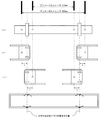
照明装置固定部材1を二つ用いて一つの発光部ユニット100を天井面Cに設置する様子を、図7を参照しながら説明する。本実施形態に係る照明装置固定部材1を用いることにより、アンカーボルトピッチが800mmである建造物の天井面に発光部ユニット100を設置する場合にも、アンカーボルトピッチが600mmである建造物の天井面に発光部ユニット100を設置する場合にも対応可能である。
図7(a)に示すように、従来の照明装置固定部材は天井面Cに設けられた開口部Wとほぼ同じくらいの大きさを有しており、アンカーボルトピッチが800mmの建造物の場合に使用するアンカーボルト取付孔二つと、アンカーボルトピッチが600mmの建造物の場合に使用するアンカーボルト取付孔二つの合計四つのアンカーボルト取付孔が設けられたものであるか、あるいはアンカーボルトピッチが800mmの建造物用固定部材とアンカーボルトピッチが600mmの建造物用固定部材という二つの固定部材を使い分けるかしていた。
アンカーボルトピッチが800mmの建造物の場合は、図7(b)に示すように、本実施形態に係る照明装置固定部材1二つ(以下、左側を1L、右側を1Rと表記する。)を当接部3a、3bがそれぞれ外側に向かって突出するように二本のアンカーボルトBにそれぞれ取り付ける。照明装置固定部材1のアンカーボルト取付孔5から左右一対のV字ばね取付孔4a、4bのそれぞれの中心を結んだ仮想線Hまでの垂線距離Lは50mmであるから、このように二つの照明装置固定部材1L、1RをアンカーボルトBに取り付ければ、左側の照明装置固定部材1LのV字ばね取付孔4a、4bのそれぞれの中心を結んだ仮想線Hから、右側の照明装置固定部材1RのV字ばね取付孔4a、4bのそれぞれの中心を結んだ仮想線Hまでの距離は700mmとなる。発光部ユニット100の各長辺上の二つのV字ばね40は700mm離して配置されているため、発光部ユニット100の四つのV字ばね40を二つの照明装置固定部材1L、1RそれぞれのV字ばね取付孔4a、4bに掛止することができる。
次に、アンカーボルトピッチが600mmの建造物の場合は、図7(c)に示すように、二つの照明装置固定部材1L、1Rを当接部3a、3bがそれぞれ内側に向かって突出するように二本のアンカーボルトBにそれぞれ取り付ける。このように二つの照明装置固定部材1L、1RをアンカーボルトBに取り付ければ、左側の照明装置固定部材1LのV字ばね取付孔4a、4bのそれぞれの中心を結んだ仮想線Hから、右側の照明装置固定部材1RのV字ばね取付孔4a、4bのそれぞれの中心を結んだ仮想線Hまでの距離は、図7(b)と同様にやはり700mmとなる。発光部ユニット100の各長辺上の二つのV字ばね40は700mm離して配置されているため、発光部ユニット100の四つのV字ばね40を二つの照明装置固定部材1L、1RそれぞれのV字ばね取付孔4a、4bに掛止することができる。
本実施形態に係る照明装置固定部材1は、アンカーボルト取付孔5が基部2の両側辺21a、21bの中間線上にあるため、上述のように照明装置固定部材1を天井面Cに対して水平に半回転(180度回転)させても用いることができる。このように半回転させて用いることにより一つの照明装置固定部材1においてオフセット幅の2倍(図7(b)(c)の本実施形態においては垂線距離L×2=100mm)の分だけ異なる二つのアンカーボルトピッチに容易に対応することができる。すなわち、二つの照明装置固定部材1L、1Rを正対させて用いる場合と、二つの照明装置固定部材1L、1Rをそれぞれ天井面Cに対して水平に半回転させて用いる場合とを比較すると、左右一対のV字ばね取付孔4a、4bの位置を固定して考えると二つの照明装置固定部材1L、1Rのアンカーボルト取付孔5間の距離を最大200mm変動させることができるため、アンカーボルトピッチが800mmの建造物にも600mmの建造物にも用いることができる。なお、二つの照明装置固定部材1L、1Rのうち片方だけを半回転させて用いれば、アンカーボルトピッチが700mmの建造物にも用いることができる。またアンカーボルト取付孔5は長孔であるので(長軸の長さ20mm)、アンカーボルトピッチが施工時に多少ずれたとしても対応できるようになっている。
本実施形態に係る照明装置固定部材1によれば、照明装置固定部材1の両側の当接部3a、3bが室内天井面Cに設けられた開口部Wの端縁部に当接し、この状態で当接部3a、3bを開口部Wの端縁部に固定することができるため、発光部ユニット100の重さをアンカーボルトBのみならず室内天井面Cの開口部Wの端縁部を含む合計三箇所で安定的に支えることができる。そのため、従来同様の取付性能を維持したまま、それぞれの照明装置固定部材1の大きさを小さくすることにより軽量化を図り、製造コストを低減することができる。
また、当接部3a、3bが基部2のアンカーボルト取付孔5が位置している側に突出するように延伸されており、突出した当接部3a、3bがアンカーボルト取付孔5を中心にしてV字ばね取付孔4a、4bの反対側にあることにより、発光部ユニット100のV字ばね40を照明装置固定部材1のV字ばね取付孔4a、4bに掛止し、照明装置固定部材1に鉛直下方向の荷重がかかった場合に、突出した当接部3a、3bが開口部Wの端縁部に押し付けられるため、照明装置の取付状態を安定したものとすることができる。
以上、本発明に係る照明装置について図面に基づいて説明してきたが、本発明は上記実施形態に限定されることはなく、種々の変更実施が可能である。
1 照明装置固定部材
2 基部
3a、3b 当接部
4a、4b V字ばね取付孔
5 アンカーボルト取付孔
6 ナット
100 発光部ユニット
10 発光部
11 導光板
111 出射光面
12 反射シート
13 光源
20 外枠部材
201 取付爪
30 補強部材
40 V字ばね
50 電源ユニット
C 天井面
W 開口部
B アンカーボルト
2 基部
3a、3b 当接部
4a、4b V字ばね取付孔
5 アンカーボルト取付孔
6 ナット
100 発光部ユニット
10 発光部
11 導光板
111 出射光面
12 反射シート
13 光源
20 外枠部材
201 取付爪
30 補強部材
40 V字ばね
50 電源ユニット
C 天井面
W 開口部
B アンカーボルト
Claims (5)
- 建造物躯体から鉛直下方向に延設された複数のアンカーボルトを用いて照明装置を室内天井面に取り付けるために、前記室内天井面に設けられた開口部近傍に二つ一組で設置される照明装置固定部材であって、
前記複数のアンカーボルトのうちの一本のアンカーボルトが挿通されるアンカーボルト取付孔が設けられた平板状の基部と、該基部の両側辺部に設けられた二つの当接部とを備え、
前記照明装置に設けられたV字ばねを掛止する左右一対のV字ばね取付孔が前記基部の前記両側辺部に沿って対称に設けられており、
前記アンカーボルト取付孔に前記一本のアンカーボルトを挿通して前記照明装置固定部材を前記一本のアンカーボルトに固定したときに、前記二つの当接部が前記開口部の対向する二つの端縁部にそれぞれ当接することを特徴とする照明装置固定部材。 - 前記アンカーボルト取付孔から前記左右一対のV字ばね取付孔のそれぞれまでの距離が等しく、かつ前記アンカーボルト取付孔が前記左右一対のV字ばね取付孔のそれぞれの中心を結んだ仮想線と重ならずオフセットしていることを特徴とする、請求項1に記載の照明装置固定部材。
- 前記アンカーボルト取付孔から前記左右一対のV字ばね取付孔のそれぞれの中心を結んだ仮想線までの垂線距離が50mmであることを特徴とする、請求項2に記載の照明装置固定部材。
- 前記当接部が、前記基部において前記アンカーボルト取付孔が位置している側に突出するように延伸されていることを特徴とする、請求項1~3のいずれか1項に記載の照明装置固定部材。
- 請求項1~4のいずれか1項に記載の照明装置固定部材を二つ用いて一つの照明装置を天井面に取り付けた照明システム。
Priority Applications (1)
| Application Number | Priority Date | Filing Date | Title |
|---|---|---|---|
| JP2018503391A JP6802834B2 (ja) | 2016-03-03 | 2017-03-02 | 照明装置固定部材 |
Applications Claiming Priority (2)
| Application Number | Priority Date | Filing Date | Title |
|---|---|---|---|
| JP2016041510 | 2016-03-03 | ||
| JP2016-041510 | 2016-03-03 |
Publications (1)
| Publication Number | Publication Date |
|---|---|
| WO2017150647A1 true WO2017150647A1 (ja) | 2017-09-08 |
Family
ID=59743033
Family Applications (1)
| Application Number | Title | Priority Date | Filing Date |
|---|---|---|---|
| PCT/JP2017/008216 Ceased WO2017150647A1 (ja) | 2016-03-03 | 2017-03-02 | 照明装置固定部材 |
Country Status (2)
| Country | Link |
|---|---|
| JP (1) | JP6802834B2 (ja) |
| WO (1) | WO2017150647A1 (ja) |
Families Citing this family (1)
| Publication number | Priority date | Publication date | Assignee | Title |
|---|---|---|---|---|
| JP2024029711A (ja) * | 2022-08-22 | 2024-03-06 | パナソニックIpマネジメント株式会社 | 表示装置 |
Citations (2)
| Publication number | Priority date | Publication date | Assignee | Title |
|---|---|---|---|---|
| JP2013096457A (ja) * | 2011-10-28 | 2013-05-20 | Shoichi Kanai | 板状部材取付け装置 |
| JP2014089882A (ja) * | 2012-10-30 | 2014-05-15 | Sharp Corp | 照明装置 |
-
2017
- 2017-03-02 JP JP2018503391A patent/JP6802834B2/ja not_active Expired - Fee Related
- 2017-03-02 WO PCT/JP2017/008216 patent/WO2017150647A1/ja not_active Ceased
Patent Citations (2)
| Publication number | Priority date | Publication date | Assignee | Title |
|---|---|---|---|---|
| JP2013096457A (ja) * | 2011-10-28 | 2013-05-20 | Shoichi Kanai | 板状部材取付け装置 |
| JP2014089882A (ja) * | 2012-10-30 | 2014-05-15 | Sharp Corp | 照明装置 |
Also Published As
| Publication number | Publication date |
|---|---|
| JPWO2017150647A1 (ja) | 2018-12-27 |
| JP6802834B2 (ja) | 2020-12-23 |
Similar Documents
| Publication | Publication Date | Title |
|---|---|---|
| US8337041B2 (en) | Surface mounted lighting fixture | |
| US9732904B1 (en) | Adjustable hanger bar assembly for luminaires | |
| JP6575900B2 (ja) | 光源ユニットおよび照明器具 | |
| US20200244054A1 (en) | Cable support bracket | |
| JP7478505B2 (ja) | 照明器具 | |
| JP2014149972A (ja) | 照明器具 | |
| WO2017150647A1 (ja) | 照明装置固定部材 | |
| JP6145917B2 (ja) | 光源装置及びそれを用いた照明器具 | |
| JP6350947B2 (ja) | 照明器具 | |
| JP2017139192A (ja) | 照明装置 | |
| JP6404384B2 (ja) | 照明器具、光源部品および取付部品 | |
| CN209622719U (zh) | 照明器具及照明装置 | |
| KR20160123170A (ko) | 마감패널 결합구 및 이를 구비한 천장 및 벽면 마감장치 | |
| JP6132873B2 (ja) | 照明装置 | |
| JP2024149223A (ja) | 照明装置及び照明器具 | |
| JP2014017149A (ja) | 照明装置 | |
| JP6372658B2 (ja) | 照明器具 | |
| JP7051501B2 (ja) | 光源ユニット、および照明器具 | |
| JP2014137932A (ja) | 光源装置及びそれを用いた照明器具 | |
| JP6811809B2 (ja) | 照明装置 | |
| JP6887105B2 (ja) | 照明器具 | |
| JP6750938B2 (ja) | 照明装置及び光源ユニット | |
| JP7634226B2 (ja) | 照明器具 | |
| JP6967474B2 (ja) | 光源ユニット、および照明器具 | |
| JP7203354B2 (ja) | 照明器具 |
Legal Events
| Date | Code | Title | Description |
|---|---|---|---|
| WWE | Wipo information: entry into national phase |
Ref document number: 2018503391 Country of ref document: JP |
|
| NENP | Non-entry into the national phase |
Ref country code: DE |
|
| 121 | Ep: the epo has been informed by wipo that ep was designated in this application |
Ref document number: 17760111 Country of ref document: EP Kind code of ref document: A1 |
|
| 122 | Ep: pct application non-entry in european phase |
Ref document number: 17760111 Country of ref document: EP Kind code of ref document: A1 |