WO2017150590A1 - Information processing system - Google Patents
Information processing system Download PDFInfo
- Publication number
- WO2017150590A1 WO2017150590A1 PCT/JP2017/008032 JP2017008032W WO2017150590A1 WO 2017150590 A1 WO2017150590 A1 WO 2017150590A1 JP 2017008032 W JP2017008032 W JP 2017008032W WO 2017150590 A1 WO2017150590 A1 WO 2017150590A1
- Authority
- WO
- WIPO (PCT)
- Prior art keywords
- product
- unit
- camera
- moving object
- shelf
- Prior art date
Links
Images


Classifications
-
- G—PHYSICS
- G06—COMPUTING; CALCULATING OR COUNTING
- G06Q—INFORMATION AND COMMUNICATION TECHNOLOGY [ICT] SPECIALLY ADAPTED FOR ADMINISTRATIVE, COMMERCIAL, FINANCIAL, MANAGERIAL OR SUPERVISORY PURPOSES; SYSTEMS OR METHODS SPECIALLY ADAPTED FOR ADMINISTRATIVE, COMMERCIAL, FINANCIAL, MANAGERIAL OR SUPERVISORY PURPOSES, NOT OTHERWISE PROVIDED FOR
- G06Q20/00—Payment architectures, schemes or protocols
- G06Q20/08—Payment architectures
- G06Q20/20—Point-of-sale [POS] network systems
- G06Q20/208—Input by product or record sensing, e.g. weighing or scanner processing
-
- G—PHYSICS
- G07—CHECKING-DEVICES
- G07G—REGISTERING THE RECEIPT OF CASH, VALUABLES, OR TOKENS
- G07G1/00—Cash registers
- G07G1/0018—Constructional details, e.g. of drawer, printing means, input means
-
- G—PHYSICS
- G06—COMPUTING; CALCULATING OR COUNTING
- G06Q—INFORMATION AND COMMUNICATION TECHNOLOGY [ICT] SPECIALLY ADAPTED FOR ADMINISTRATIVE, COMMERCIAL, FINANCIAL, MANAGERIAL OR SUPERVISORY PURPOSES; SYSTEMS OR METHODS SPECIALLY ADAPTED FOR ADMINISTRATIVE, COMMERCIAL, FINANCIAL, MANAGERIAL OR SUPERVISORY PURPOSES, NOT OTHERWISE PROVIDED FOR
- G06Q20/00—Payment architectures, schemes or protocols
- G06Q20/08—Payment architectures
- G06Q20/20—Point-of-sale [POS] network systems
- G06Q20/201—Price look-up processing, e.g. updating
-
- G—PHYSICS
- G06—COMPUTING; CALCULATING OR COUNTING
- G06Q—INFORMATION AND COMMUNICATION TECHNOLOGY [ICT] SPECIALLY ADAPTED FOR ADMINISTRATIVE, COMMERCIAL, FINANCIAL, MANAGERIAL OR SUPERVISORY PURPOSES; SYSTEMS OR METHODS SPECIALLY ADAPTED FOR ADMINISTRATIVE, COMMERCIAL, FINANCIAL, MANAGERIAL OR SUPERVISORY PURPOSES, NOT OTHERWISE PROVIDED FOR
- G06Q20/00—Payment architectures, schemes or protocols
- G06Q20/38—Payment protocols; Details thereof
- G06Q20/40—Authorisation, e.g. identification of payer or payee, verification of customer or shop credentials; Review and approval of payers, e.g. check credit lines or negative lists
- G06Q20/401—Transaction verification
- G06Q20/4014—Identity check for transactions
- G06Q20/40145—Biometric identity checks
-
- G—PHYSICS
- G06—COMPUTING; CALCULATING OR COUNTING
- G06Q—INFORMATION AND COMMUNICATION TECHNOLOGY [ICT] SPECIALLY ADAPTED FOR ADMINISTRATIVE, COMMERCIAL, FINANCIAL, MANAGERIAL OR SUPERVISORY PURPOSES; SYSTEMS OR METHODS SPECIALLY ADAPTED FOR ADMINISTRATIVE, COMMERCIAL, FINANCIAL, MANAGERIAL OR SUPERVISORY PURPOSES, NOT OTHERWISE PROVIDED FOR
- G06Q30/00—Commerce
- G06Q30/06—Buying, selling or leasing transactions
-
- G—PHYSICS
- G06—COMPUTING; CALCULATING OR COUNTING
- G06T—IMAGE DATA PROCESSING OR GENERATION, IN GENERAL
- G06T5/00—Image enhancement or restoration
- G06T5/40—Image enhancement or restoration by the use of histogram techniques
-
- G—PHYSICS
- G06—COMPUTING; CALCULATING OR COUNTING
- G06T—IMAGE DATA PROCESSING OR GENERATION, IN GENERAL
- G06T7/00—Image analysis
-
- G—PHYSICS
- G06—COMPUTING; CALCULATING OR COUNTING
- G06T—IMAGE DATA PROCESSING OR GENERATION, IN GENERAL
- G06T7/00—Image analysis
- G06T7/20—Analysis of motion
-
- G—PHYSICS
- G06—COMPUTING; CALCULATING OR COUNTING
- G06T—IMAGE DATA PROCESSING OR GENERATION, IN GENERAL
- G06T7/00—Image analysis
- G06T7/60—Analysis of geometric attributes
-
- G—PHYSICS
- G06—COMPUTING; CALCULATING OR COUNTING
- G06T—IMAGE DATA PROCESSING OR GENERATION, IN GENERAL
- G06T7/00—Image analysis
- G06T7/70—Determining position or orientation of objects or cameras
- G06T7/73—Determining position or orientation of objects or cameras using feature-based methods
-
- G—PHYSICS
- G06—COMPUTING; CALCULATING OR COUNTING
- G06T—IMAGE DATA PROCESSING OR GENERATION, IN GENERAL
- G06T7/00—Image analysis
- G06T7/90—Determination of colour characteristics
-
- G—PHYSICS
- G06—COMPUTING; CALCULATING OR COUNTING
- G06V—IMAGE OR VIDEO RECOGNITION OR UNDERSTANDING
- G06V20/00—Scenes; Scene-specific elements
- G06V20/50—Context or environment of the image
- G06V20/52—Surveillance or monitoring of activities, e.g. for recognising suspicious objects
-
- G—PHYSICS
- G07—CHECKING-DEVICES
- G07G—REGISTERING THE RECEIPT OF CASH, VALUABLES, OR TOKENS
- G07G1/00—Cash registers
-
- G—PHYSICS
- G07—CHECKING-DEVICES
- G07G—REGISTERING THE RECEIPT OF CASH, VALUABLES, OR TOKENS
- G07G1/00—Cash registers
- G07G1/0036—Checkout procedures
- G07G1/0045—Checkout procedures with a code reader for reading of an identifying code of the article to be registered, e.g. barcode reader or radio-frequency identity [RFID] reader
- G07G1/0054—Checkout procedures with a code reader for reading of an identifying code of the article to be registered, e.g. barcode reader or radio-frequency identity [RFID] reader with control of supplementary check-parameters, e.g. weight or number of articles
- G07G1/0063—Checkout procedures with a code reader for reading of an identifying code of the article to be registered, e.g. barcode reader or radio-frequency identity [RFID] reader with control of supplementary check-parameters, e.g. weight or number of articles with means for detecting the geometric dimensions of the article of which the code is read, such as its size or height, for the verification of the registration
-
- G—PHYSICS
- G07—CHECKING-DEVICES
- G07G—REGISTERING THE RECEIPT OF CASH, VALUABLES, OR TOKENS
- G07G1/00—Cash registers
- G07G1/12—Cash registers electronically operated
-
- G—PHYSICS
- G07—CHECKING-DEVICES
- G07G—REGISTERING THE RECEIPT OF CASH, VALUABLES, OR TOKENS
- G07G1/00—Cash registers
- G07G1/12—Cash registers electronically operated
- G07G1/14—Systems including one or more distant stations co-operating with a central processing unit
Definitions
- the present invention relates to an information processing system.
- the present invention has been made in view of such circumstances, and when a purchaser purchases a product displayed in a store, the time required for automating the settlement of the price of the product and the settlement of the price of the product is reduced. It is intended to enable shortening and prevent fraud such as shoplifting by shoppers and cashiers.
- an information processing system includes: A moving object tracking means for discovering a moving object such as a person or a basket moving in the store, defining the area of the moving object, and capturing an image while continuously tracking the movement of the moving object;
- the state in the shelf in the store is always imaged, the captured images before and after the object is taken out from the shelf are compared, the product to be recognized is defined as an area from the captured image, and the defined image area is Shelf product recognition means for identifying the product;
- Checkout means for checking out the specified product, Is provided.
- the settlement of the price of the product is automated, the time required for the settlement of the price of the product is shortened, and fraud prevention by shoppers and cashiers is prevented.
- FIG. 2 is a schematic perspective view illustrating a configuration example of an appearance of a cash register terminal employed in the first embodiment. It is a block diagram which shows the structure of the goods recognition system as Embodiment 1 of the information processing system of this invention. It is a block diagram which shows the hardware constitutions of a server among the product recognition systems of FIG. It is a block diagram which shows the hardware constitutions of a cash register terminal among the goods recognition systems of FIG.
- FIG. 7 It is a functional block diagram which shows an example of a functional structure with the server of FIG. 5, and the cash register terminal of FIG. The example of the imaging screen of the object set
- It is a block diagram which shows the structure of the goods recognition system as Embodiment 2 of the information processing system of this invention.
- It is a block diagram which shows the hardware constitutions of a sales floor apparatus among the merchandise recognition systems of FIG.
- It is a functional block diagram which shows an example of a functional structure with the server of FIG. 5, the cash register terminal of FIG. 6, and the sales floor apparatus of FIG.
- It is a functional block diagram which shows the detailed functional structural example of the positional information management part with which the sales floor apparatus of FIG. 16 was equipped.
- FIG. 17 is a functional block diagram illustrating a detailed functional configuration example of a book number counting unit provided in the sales floor device of FIG. 16. It is a flowchart explaining the automatic payment process which the server of FIG. 16, a cash register terminal, and a sales floor apparatus perform. It is a flowchart in the case of verifying the number information of goods and the number of books to be settled in step S210 of FIG. It is a figure which shows the example of a layout of the supermarket which employ
- FIG. It is a block diagram which shows the structure of the goods recognition system as Embodiment 3. It is a block diagram which shows the hardware constitutions of a sales floor apparatus among the goods recognition systems of FIG.
- FIG. 26 is a functional block diagram illustrating a detailed functional configuration example of a moving object tracking unit provided in the sales floor device in FIG. 25. It is a functional block diagram which shows the detailed functional structural example of the shelf goods recognition part with which the sales floor apparatus of FIG. 25 was equipped. It is a functional block diagram which shows the detailed functional structural example of the basket goods recognition part with which the sales floor apparatus of FIG. 25 was equipped. It is a flowchart explaining the basic flow of the automatic adjustment process which the server of FIG. 25, a sales floor apparatus, and a payment machine perform.
- FIG. 25 It is a flowchart explaining the process which recognizes the goods in the basket of the automatic adjustment process which the server sales floor apparatus and adjustment machine of FIG. 25 perform. It is a figure which shows the example of a layout of the supermarket which employ
- FIG. It is a block diagram which shows the structure of the goods recognition system as Embodiment 4 of the information processing system of this invention. It is a figure which shows the hardware constitutions of the adjustment gate among the goods recognition systems of FIG. It is a functional block diagram which shows an example of a function structure of the server of FIG. 5, the sales floor apparatus of FIG. 24, and the adjustment gate of FIG.
- FIG. 1 is a table listing the main points of Embodiments 1 to 4 of the information processing system of the present invention.
- execution store column in FIG. 1
- the implementation stores of the first to fourth embodiments are described.
- the first embodiment is an information processing system mainly assuming application at a convenience store.
- this implementation store is merely an example, and the application destination of each of Embodiments 1 to 4 is not particularly limited.
- the implementation store of Embodiment 1 may be a retail store such as a supermarket, a restaurant, or a store where payment is performed.
- the “settlement place” column in FIG. 1 describes a place where the shopper performs settlement in each of the first to fourth embodiments.
- the checkout location in the first and second embodiments illustrates a cash register terminal.
- the cash register terminal has a function of specifying an object as a product and adjusting the product.
- the settlement place in Embodiment 3 is a cash register.
- the cash register stand has a function of paying out the merchandise on which an item already specified as a merchandise is placed.
- the settlement place in Embodiment 4 illustrates the settlement gate.
- the checkout gate has a function of checking out the product without placing what has already been specified as the product from the object on the cash register.
- the information processing system of the first embodiment is an information processing system that performs automatic settlement of commodities placed at a cash register terminal.
- the details of each embodiment are described in the “details” column in FIG. That is, for example, the information processing system according to the first embodiment recognizes a hand-held product placed on a cash register terminal by a cash register camera installed on the cash register terminal, and performs automatic settlement of the product.
- the product recognition system includes one or more sensing devices that capture an image of an object.
- various devices such as a temperature sensor and a distance sensor can be adopted in addition to an image sensor (camera or the like).
- An image captured by an image sensor such as a camera is hereinafter referred to as a “captured image”.
- a captured image including an object as a subject is hereinafter referred to as an “object captured image”.
- a captured image including a product as a subject is hereinafter referred to as a “product captured image”.
- the product recognition system recognizes the presence of an object based on an object captured image that includes an object placed on a cash register terminal as a subject.
- the cash register terminal includes one or more cashier cameras as an example of a sensing device.
- the cashier camera images a predetermined area of the cashier terminal.
- the registration camera images a predetermined area before an object is placed.
- the cashier camera images a predetermined area after the object is placed in the predetermined area. Therefore, in the commodity recognition system of the first embodiment, the cash register terminal compares the captured image before the object is placed in the predetermined area of the cash register terminal with the captured image of the object after the object is placed in the predetermined area of the cash register terminal.
- the cash register terminal specifies which product each of the recognized objects is by an object recognition method based on image recognition.
- a product candidate is created by deep learning, and then a method for identifying the product with high accuracy by adopting a verification function is employed.
- the cashier terminal recognizes the quantity of the next specified product. In the first embodiment, the next specified product is settled.
- the product recognition system of Embodiment 2 is applied to a store such as a bookstore.
- the product recognition system according to the second embodiment will be described as a “shelves” including a shelf (hereinafter referred to as a “shelf”) between a shelf installed in a sales floor in a bookstore and a shelf such as a wagon. )
- a shelf hereinafter referred to as a “shelf”
- the shopper was tracked until it was placed on the cashier terminal, and if the book was placed on the cashier terminal, the number of books placed was recognized. Then, the book is identified as a product by specifying the book, and the book is automatically settled.
- the product recognition system of the third embodiment is applied to retail stores such as supermarkets. Specifically, the product recognition system according to the third embodiment recognizes baskets (shopping carts and carts) placed on the sales floor of a retail store such as a supermarket, and tracks the baskets moving on the sales floor. In the product recognition system according to the third embodiment, when an object is taken from the shelf, the object is recognized and specified as a product, and the baskets are placed on the cash register, so that a list of products placed in the baskets can be obtained. It is read out and the product is automatically settled.
- baskets shopping carts and carts
- the product recognition system of Embodiment 4 is applied to a retail store such as a supermarket. Specifically, not only the shoppers and shopping carts and carts placed in the supermarket, but also the carts including the shoppers' my bags, shopping bags, etc. and the shoppers are recognized and tracked as moving objects.
- the product recognition system of the fourth embodiment the product is recognized and specified when an object is removed from the shelf, and the product can be automatically settled at the cash register even if the product is not placed on the cash register terminal.
- Embodiment 1 The information processing system according to the first embodiment is a product recognition system having a cash register terminal 2 as shown in FIG. 3 that is employed in a store such as a convenience store as shown in FIG.
- the information processing system according to the first embodiment is configured so that automatic payment can be made by placing a product on a cash register terminal.
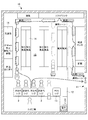
- FIG. 2 is a diagram illustrating a layout example in a case where a store that employs the information processing system according to the first embodiment is a convenience store.
- a cashier counter 12 is installed near the entrance 11 in the store 10.
- an unmanned cashier terminal 2 for automatically paying out merchandise is installed.
- a manned register 13 is installed next to the cash register terminal 2.
- a plurality of shelf racks 14 for displaying products are installed, and a space 15 between the facing racks 14 is a passage 15 for a shopper to move.
- the goods in the shelf are picked up by a shopper who has moved through the passage 15 and placed in a predetermined area of the cash register terminal 2 (a predetermined area A in FIG. 3 to be described later).
- the products placed in the predetermined area are automatically settled by the register terminal 2 specifying a plurality of products at a time with a predetermined operation on the cashier terminal 2 of the shopper as a trigger.
- resistor 13 as before, a salesclerk recognizes goods one by one with a barcode, and settles.
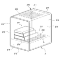
- FIG. 3 is a schematic perspective view showing an example of the external configuration of the cash register terminal 2.
- the cash register terminal 2 includes a surrounding portion 270 surrounding a predetermined area A on which an object is placed.
- the surrounding portion 270 includes a top plate portion 271, a bottom plate portion 272, and a pair of side plate portions 273.
- a registration camera 211 that images the predetermined area A is fixed to each of the top plate portion 271 and the pair of side plate portions 273.
- the registration camera 211 images an object placed in the predetermined area A.
- FIG. 3 only three registration cameras 211 are drawn. However, as will be described later, five registration cameras may be used, and at least one registration camera 211 is sufficient, and the number is not limited.
- the cash register terminal 2 also includes a camera that captures an image of a shopper's face and hands.
- a housing part 275 is installed on the bottom plate part 272.
- a receipt output unit and a display unit (not shown in FIG. 3, a receipt output unit R and a display unit D of the output unit 206 in FIG. 6 to be described later) are provided on the front surface of the housing unit 275.
- a translucent plate 276 on which an object is placed is installed on the housing portion 275.
- the surface of the upper surface of the plate 276 is defined as a predetermined area A.
- the board surface of the plate 276 is formed in a wave shape.
- the wave shape may be not only a sine wave shape but also a rectangular wave, and the pitch and amplitude may be not only equal but also unequal.
- the plate 276 is such that the predetermined area A is formed by repeatedly forming a concave portion and a convex portion, so that at least a part of a cylindrical or spherical object is sandwiched between the convex portion and the convex portion, It can be prevented from rolling.
- An illumination unit 208 that illuminates the predetermined area A is provided in the plate 276 and the top plate part 271 of the surrounding part 270.
- the illumination unit 208 may be provided on the side plate part 273 of the surrounding part 270.
- the illumination unit 208 emits light not only in white but also in various colors such as blue, red, and the like.
- the illumination unit 208 emits light so that the shadow of an object placed in the predetermined area A does not occur or decreases in the predetermined area A.
- the Go unit 270 indicates whether the cashier terminal 2 is in a normal standby state, a state in which it is being settled, whether the store clerk is operating, or whether an abnormal situation has occurred.
- the presentation unit 210 can be discolored so that it can be visually recognized by color.
- At least the top plate portion 271 and the side plate portion 273 of the surrounding portion 270 may be configured by an instantaneous light control sheet so as to be switched between a transparent state that becomes transparent and an opaque state that becomes opaque. In that case, the visibility of the predetermined area A can be ensured by making the surrounding portion 270 transparent. By making the surrounding portion 270 opaque, it is possible to acquire an object captured image while suppressing the influence of external light during shooting.
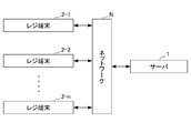
- FIG. 4 is a configuration diagram showing the configuration of the product recognition system as Embodiment 1 of the information processing system of the present invention.
- the product recognition system of the first embodiment includes a server 1 and n (n is an arbitrary integer value of 1 or more) cash register terminals 2-1 to 2-n.
- the server 1 and the n cashier terminals 2-1 to 2-n are connected to each other via a network N such as the Internet.
- the cashier terminal 2 For convenience of explanation, only one server 1 in FIG. 4 is drawn, but there may actually be a plurality of servers.
- the cashier terminal 2 when it is not necessary to individually distinguish the cashier terminals 2-1 to 2-n, they are collectively referred to as “the cashier terminal 2”.
- the server 1 executes each process in order to manage each operation of the cash register terminal 2.
- the cash register terminal 2 is placed on the cash register counter 12 shown in FIG.
- the cash register terminal 2 specifies the quantity of objects placed in the predetermined area A of the cash register terminal 2 by the shopper, specifies the product, and automatically pays out.
- FIG. 5 is a block diagram illustrating a hardware configuration of the server 1 in the information processing system according to the first embodiment illustrated in FIG. 4.
- the server 1 includes a CPU (Central Processing Unit) 101, a ROM (Read Only Memory) 102, a RAM (Random Access Memory) 103, a bus 104, an input / output interface 105, an output unit 106, an input unit 107, A storage unit 108, a communication unit 109, and a drive 110.
- a CPU Central Processing Unit
- ROM Read Only Memory
- RAM Random Access Memory
- the CPU 101 executes various processes according to a program stored in the ROM 102 or a program loaded from the storage unit 108 to the RAM 103.
- the RAM 103 also stores data necessary for the CPU 101 to execute various processes as appropriate.
- the CPU 101, the ROM 102, and the RAM 103 are connected to each other via the bus 104.
- An input / output interface 105 is also connected to the bus 104.
- An output unit 106, an input unit 107, a storage unit 108, a communication unit 109, and a drive 110 are connected to the input / output interface 105.
- the output unit 106 includes a display, a speaker, and the like, and outputs various types of information as images and sounds.
- the input unit 107 includes a keyboard, a mouse, and the like, and inputs various information.
- the storage unit 108 includes a hard disk, a DRAM (Dynamic Random Access Memory), and the like, and stores various data. As shown in FIG. 4, the communication unit 109 communicates with the cashier terminal 2 via a network N including the Internet.
- a network N including the Internet.
- a removable medium 120 made of a magnetic disk, an optical disk, a magneto-optical disk, a semiconductor memory, or the like is appropriately attached to the drive 110.
- the program read from the removable medium 120 by the drive 110 is installed in the storage unit 108 as necessary.
- the removable medium 120 can also store various data stored in the storage unit 108 in the same manner as the storage unit 108.
- FIG. 6 is a block diagram showing a hardware configuration of the cash register terminal 2 in the information processing system according to the first embodiment shown in FIG.
- the cash register terminal 2 includes a CPU 201, a ROM 202, a RAM 203, a bus 204, an input / output interface 205, an output unit 206, an input unit 207, a lighting unit 208, a light shielding unit 209, a presentation unit 210, a register A camera 211, a storage unit 212, a communication unit 213, and a drive 214 are provided.
- a removable medium 220 is appropriately attached to the drive 214.
- the CPU 201, the ROM 202, the RAM 203, the bus 204, the input / output interface 205, the storage unit 212, the communication unit 213, the drive 214, and the removable medium 220 of the cash register terminal 2 are configured in the same manner as those of the server 1.
- the output unit 206 is provided in the housing unit 275 shown in FIG.
- the output unit 206 includes a display unit D that displays information related to products, information related to payment, and a receipt output unit R that outputs receipts.
- the input unit 207 is provided in the housing unit 275 shown in FIG.
- the input unit 207 includes a touch panel (not shown) and a card reader unit C.
- the light shielding unit 209 switches the surrounding part 270 shown in FIG. 3 between a transparent state and an opaque state when the surrounding part 270 is formed of an instantaneous light control sheet.
- the presenting unit 210 can know whether the state of the cash register terminal 2 is in a normal standby state, a state in which payment is being made, whether the store clerk is operating, or whether an abnormal situation has occurred.
- the presentation unit 210 shown in FIG. 3 switches to emit light in different colors.
- the presentation unit 210 is provided not only on the front side but also on the back side.
- the registration camera 211 captures an image of an object placed in the predetermined area A, and outputs one or more captured images obtained as a result thereof as an object captured image.
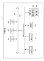
- FIG. 7 is a functional block diagram showing an example of a functional configuration of the server 1 of FIG. 5 and the cash register terminal 2 of FIG.
- the DB management unit 141 functions.
- a product DB 131 is provided in an area of the storage unit 108 of the server 1.
- the product DB 131 is a DB (Data Base) that stores information about products.
- the CPU 201 of the cash register terminal 2 includes a light emission control unit 228, a light shielding control unit 229, a presentation control unit 230, a personal authentication unit 231, an image acquisition unit 232, and an object recognition unit 233.
- the object quantity recognizing unit 234, the product specifying unit 235, the trade limited product determining unit 236, the settlement unit 237, and the display control unit 238 function.
- the cash register terminal 2 includes a DB information holding unit 241 that holds personal information and product information.
- the light emission control unit 228 of the CPU 201 of the cash register terminal 2 performs control to switch between a state in which the illumination unit 208 emits light at a timing when an object is imaged and a state in which the illumination unit 208 does not emit light at a timing at which an object is not imaged. Control is performed to switch the emission color of the illumination unit 208 in accordance with the situation of recognizing the placed object.
- the light shielding control unit 229 switches the surrounding part 270 between an opaque state and a transparent state when the surrounding part 270 is formed of an instantaneous light control sheet.
- the light-shielding control unit 229 is configured such that the light-shielding unit 209 provided in the surrounding unit 270 captures an object placed in the predetermined area A from an opaque state at a timing, and a transparent state at a timing when the image is not captured. Control to switch to.
- the presentation control unit 230 performs control so that the presentation unit 210 changes the emission color that presents the state of the cash register terminal 2.
- the personal authentication unit 231 performs personal authentication of the shopper by referring to the personal information managed by the DB information holding unit 241 and the DB management unit 141 during the checkout process. Specifically, the personal authentication unit 231 performs authentication processing using various authentication methods such as face authentication, card authentication, fingerprint authentication, vein authentication, iris authentication, and the like before product image recognition. .
- the personal information managed by the DB management unit 141 includes information such as age, allergy, and halal. Therefore, the personal information acquired by the personal authentication unit 231 is used by the trade restricted product determination unit 236.
- the image acquisition unit 232 acquires an object captured image captured by the registration camera 211 with the object placed in the predetermined area A as shown in FIG.
- FIG. 8 shows an example of an imaging screen of an object placed on the cash register terminal 2.
- FIG. 8 is a diagram illustrating an example of an object captured image obtained as a result of imaging the objects X, Y, Z, and Z ′ placed in the predetermined area A by each of the three registration cameras 211.
- FIG. 8A shows an example of an object captured image obtained as a result of imaging the objects X, Y, Z, and Z ′ by the registration camera 211 fixed to the top plate portion 271 of the registration terminal 2.
- This object captured image includes six objects. Since this object captured image does not include the objects X, Y, Z, and Z ′ that are the shadows of the objects, all the objects X, Y, Z, and Z ′ placed in the predetermined area A are captured.
- FIG. 8B shows an example of an object captured image obtained as a result of imaging the objects X, Y, Z, and Z ′ by the registration camera 211 fixed to one side plate portion 273 of the registration terminal 2.
- This object captured image includes two objects. In this object captured image, the objects X, Y, Z, and Z ′ on the registration camera 211 side hide the objects on the back side.
- FIG. 8C shows a captured image obtained as a result of imaging the objects X, Y, Z, and Z ′ by the registration camera 211 fixed to the other side plate portion 273 of the registration terminal 2.
- This object captured image includes two objects. In this object captured image, the objects X, Y, Z, and Z ′ on the registration camera 211 side hide the objects on the back side.
- the two objects Z included in the respective object captured images of FIGS. 8B and 8C one is the same object Z ′, but the other is a different object.
- the object recognition unit 233 recognizes the presence of an object placed in the predetermined area A from the object captured image acquired by the image acquisition unit 232 using the predetermined image recognition method described above. That is, the object recognizing unit 233 compares the background image before the object is placed in the predetermined area A of the cash register terminal 2 and the object captured image after the object is placed, and performs object difference for each object by background difference processing. Recognize the existence of an object by defining (specifying). Note that the object recognition unit 233 uses a method other than background difference processing, and does not compare the background image before the object is placed in the predetermined area A with the object captured image after the object is placed, but only the object captured image. The presence of an object may be recognized by defining an object region from
- the object quantity recognition unit 234 recognizes the quantity of objects placed in the predetermined area A by comparing the object recognition quantity and the settlement quantity.
- the object recognition quantity is the quantity of objects recognized by the object recognition unit 233 from the object captured images captured by the plurality of registration cameras 211 of the registration terminal 2.
- the checkout quantity is the quantity of the product to be checked out.
- the object recognition quantity may vary depending on the registration camera 211 as shown in FIG. That is, in FIG. 8A, six objects are imaged, but in FIGS. 8B and 8C, two objects are imaged. In such a case, the object quantity recognition unit 234 recognizes the quantity of the object by taking a logical sum as shown in FIG.
- FIG. 9 is a diagram illustrating an example of a truth table for calculating the number of objects placed on the cash register terminal 2.
- FIG. 9 shows images of the objects X, Y, Z, and Z ′ shown in FIG. 8 taken by the first to fifth cashier cameras 211 provided in the cashier terminal 2 (FIG. 3). "If the image could not be captured, it is represented by" 0 ". Note that although the object Z and the object Z ′ are the same object, the imaged registration camera 211 is different, and thus the images are captured in different states.
- the first cash register camera 211 is represented as “cash register camera 1”, and similarly, the second through fifth cash register cameras 211 are represented as “cash register camera 2” through “cash machine camera 5”. ing.
- the object X is captured by the first, fourth, and fifth registration cameras 211.
- the object Y is imaged by the second, fourth and fifth registration cameras 211.
- the object Z is captured by the second, third and fifth registration cameras 211.
- the object Z ′ is captured by the first and third registration cameras 211.
- the object quantity recognizing unit 234 recognizes the quantity of the product by a method using logical sum. That is, even if an object overlaps and is placed in the predetermined area A, or an object is placed in the predetermined area A so as to be a shadow of another object, an object captured by any one of the registration cameras 211 is logically ORed. Is recognized as being placed in the predetermined area A.
- the object quantity recognition unit 234 informs the display control unit 238 that the quantities are different. Output.
- the product identification unit 235 matches the object whose presence is recognized by the object recognition unit 233 with the product information held in the DB information holding unit 241. That is, the product specifying unit 235 first lists product candidates using an image processing method such as specific object recognition, general object recognition, deep learning, or the like. The listed product candidates are referred to as “product candidate list S”. Thereafter, the product specifying unit 235 exhibits the verification function and specifies the product with high accuracy.
- the verification function is a function for listing the “product candidate list P” using an algorithm different from the above-described method for listing product candidates.
- the product is specified.
- a method for listing up the “product candidate list” for example, it is realized by a method of matching image information of an object obtained from an object whose existence has been recognized with image information held in the DB information holding unit 241 or the memory. May be. That is, if the feature information of both images match (exceeds a threshold value), the object whose existence is recognized by the object recognition unit 233 is a product registered in the DB information holding unit 241, and therefore the product specifying unit 235 The product is registered in the DB information holding unit 241.
- the product identification unit 235 compares the product image stored in the DB information holding unit 241 with the object captured image captured in the predetermined area A, and the feature points (similar feature points) and features that are similar to both images. Calculate the amount.
- the product identification unit 235 reads the feature points and feature quantities of the product images included in the product candidate list from the product DB 131 of the server 1.
- the product identification unit 235 compares the feature amount for each feature point of the product included in the read product candidate list with the feature amount for each feature point of the recognized object, and saves it in the DB information holding unit 241. The similar feature points of the product image being picked up and the object captured image captured in the predetermined area A are matched.
- the product specifying unit 235 compares the positional relationship using the corresponding point coordinates of each set of similar feature points, and the similar feature points that do not correspond correctly in the change due to rotation or translation (the positional relationship does not match). And the number of remaining similar feature points is calculated. The product specifying unit 235 determines that the product is unspecified when the number of similar feature points is less than the threshold.
- a product such as a lunch box that is not a packaged product may be made an unspecified product.
- the location of the side dishes may be slightly different, and in such a case, there is a risk of being an unspecified product.
- the product specifying unit 235 detects various codes such as a multi-dimensional code including a barcode written on a label attached to the product, characters such as a product name, and the DB information holding unit 241 The product name or product code may be read based on the product information stored in the product DB 131 of the server 1 to specify the product.
- the product specifying unit 235 verifies similar products and related products (hereinafter referred to as “group products”) using product information stored in the DB information holding unit 241 and the product DB 131 of the server 1. For example, the product specifying unit 235 compares the threshold values of group products of series having different sizes, colors, and the like using characteristics such as the size and color of the products. The product specifying unit 235 determines that the product is unspecified when the threshold is less than a predetermined threshold.
- the sale restriction product determination unit 236 determines whether the product specified by the product specification unit 235 corresponds to a sale restriction product based on the determination information.
- a trade-restricted product it includes (A) a product that cannot be purchased unless it reaches a certain age, such as tobacco, alcoholic beverages, etc., (B) a product whose consumption has expired or has expired, and (C) an allergic component.
- a product that cannot be purchased unless it reaches a certain age, such as tobacco, alcoholic beverages, etc. (B) a product whose consumption has expired or has expired, and (C) an allergic component.
- products that should not be ingested and products that are restricted by religion such as (D) products other than halal foods.
- the settlement unit 237 calculates the total amount for all the products specified by the product specifying unit 235. At that time, if the sale-restricted product determination unit 236 determines that there is a sale-restricted product, the restriction needs to be lifted for all of the sale-restricted products. Therefore, the settlement unit 237 reads the price of the product placed in the predetermined area A from the DB information holding unit 241 and displays it on the display unit D (FIG. 6).
- the display control unit 238 controls the output unit 206 to warn the shopper and the store clerk to confirm the product quantity when the object quantity recognition unit 234 does not match the object recognition quantity and the settlement quantity. To do.
- the display control unit 238 controls the output unit 206 so as to warn the shopper and the store clerk that the object is a sale-restricted product when the sale-restricted product determination unit 236 determines that the object is a sale-restricted product. To do. Further, when the total amount is calculated by the settlement unit 237, the output unit 206 is controlled so that the product name, price, etc. of the product are displayed to the shopper and the store clerk.
- the sale restricted product determination unit 236 determines that the object is a sale restricted product, and a warning to that effect is presented from the presentation unit 210 and the output unit 206.
- the store clerk who notices this presentation determines whether or not the restricted sale product can be sold. When it is determined that the restricted sale product can be sold, the presentation is canceled by the store clerk.
- This product recognition system includes a remote control unit 17 for instructing the release.
- the remote control unit 17 is carried by a store clerk away from the cash register terminal 2 or provided in the backyard of the store. A signal from the remote control unit 17 is input to the cashier terminal 2 communication unit 213.
- a single remote operation unit 17 can remotely operate a plurality of cash register terminals 2.
- the merchandise recognition system applied as the information processing system of the present specification includes a merchandise registration system for imaging the appearance of merchandise and registering it with merchandise information such as the price of the merchandise sold at the store 10. .
- the product registration may be performed in the store 10 or may be performed outside the store, such as a product manufacturer or a wholesaler, and the place is not limited.
- the product registration system includes a registration image generation unit (not shown), a product master registration unit, a captured image acquisition unit, and a recognition unit.
- the registration image generation unit generates an image of a product that can be placed in the predetermined area A of the cash register terminal 2 as a product registration image.
- the product master registration unit registers the product registration image generated by the registered image generation unit and the product identifier uniquely assigned to the product included in the product registration image as a subject.
- the captured image acquisition unit acquires a captured image of an object placed in the predetermined area A of the cash register terminal 2 as an object captured image.
- the product specifying unit 235 specifies which product is the object whose existence has been recognized.
- the object recognition unit 233 recognizes the presence of an object placed in the predetermined area A based on the acquired object captured image. This product recognition system matches the object captured image of the object whose existence has been recognized with the product image held in the DB information holding unit 241 or the storage unit 108 of the server 1 as described above, so that the product specifying unit Which product is specified by 235.
- a product registration image is generated, and a product identifier is assigned to the product included in the product registration image, whereby master registration based on the product identifier uniquely assigned to the product is performed. It becomes possible. Furthermore, the product recognition system provided with this product registration system can manage products for which a bar code seal cannot be attached.
- FIG. 10 is a flowchart for explaining a product settlement process executed by the server and the cash register terminal of FIG.
- an image of the predetermined area A captured in advance in a state where no object is placed in the predetermined area A of the cash register terminal 2 is stored in the image acquisition unit 232.
- the image of the predetermined area A captured in advance may be updated at a predetermined timing, and may not be updated every time the shopper uses the cash register terminal 2, and may be shared even if the shopper changes. Then, when the shopper presses the operation button of the cash register terminal, the automatic checkout process is started.
- step S ⁇ b> 101 the cashier camera 211 of the cashier terminal 2 captures an image after an object is placed on the predetermined area A of the cashier terminal 2.
- the image is input to the image acquisition unit 232 as an object captured image as shown in FIG.
- the object captured image is configured such that the shadow of the object is not generated or reduced by the illumination unit 208 illuminating the cash register terminal 2.
- the object captured image may be input to the display control unit 238 and output from the output unit 206.
- the personal authentication unit 231 authenticates the shopper personally.
- step S102 the object recognition unit 233 of the cash register terminal 2 recognizes the presence of an object placed in the predetermined area A from the object captured image acquired by the image acquisition unit 232 using the predetermined image recognition method described above. To do. That is, the object recognizing unit 233 compares the background image before the object is placed in the predetermined area A of the cash register terminal 2 and the object captured image after the object is placed, and performs object difference for each object by background difference processing. Recognize the existence of an object by defining (specifying).
- step S ⁇ b> 103 the product specifying unit 235 of the cash register terminal 2 determines whether it is possible to specify which product the object placed in the predetermined area A of the cash register terminal 2 is. If the product identification unit 235 cannot identify the product (NO in step S103), the presenting unit 210 of the cash register terminal 2 notifies the error state by color, sound, or the like. When an error state due to unspecified product is entered, the object is repositioned, and a predetermined operation is performed at the cash register terminal 2 to return to step S101, and the object is imaged again. Repositioning may be performed by a store clerk who has found an error condition, or by the shopper himself.
- an error state occurs when the system processing of the cash register terminal 2 becomes abnormal, when the characteristic part of the object cannot be imaged, or when the object overlaps or becomes a shadow, the trade restricted product is registered. For example, when the product is placed on the terminal 2 or a product or personal item is left behind on the cash register terminal 2. If the objects overlap or become shadows, by repositioning the objects, it is possible to capture which product the object is and identify the product.
- the product specifying unit 235 can specify the product in step S103 (YES in step S103)
- the product specifying unit 235 stores the product name, price, and sale restrictions held in the DB information holding unit 241 or the storage unit of the server 1. Identify the product including information such as the product. Thereby, the process proceeds to step S104.
- the specified product information may be output to the display control unit 238.
- step S104 the trade restricted product determination unit 236 executes processing of trade restricted products.
- the processing of trade-restricted products is processing for determining whether or not the specified product is a trade-restricted product.
- the trade restricted product determination unit 236 determines, for example, whether the specified product is an age-restricted product, whether it is a halal non-applicable product or a product containing allergens, whether the product has expired, or has expired. To do. Details of the processing of trade-restricted products will be described later with reference to FIG.
- the trade-restricted product determination unit 236 can execute processing of trade-restricted products for each shopper. it can.
- step S105 the settlement unit 237 settles the product placed in the predetermined area A. Specifically, the settlement unit 237 settles all the products placed in the predetermined area A by individually acquiring and summing the prices of the products specified in step S103.
- Product information such as the product name and price of the settled product is output from the display control unit 238 to the output unit 206, displayed on the display unit D of the output unit 206, printed on the receipt from the receipt output unit R, and output.
- POS Point Of Sale
- the presentation unit 210 of the cash register terminal 2 presents the fact that the quantity of the object specified by the object quantity recognition unit 234 is different from the quantity of the product specified by the product specification unit 235 and the settlement quantity. May be.
- the cash register terminal 2 can cancel the checkout process by providing a cancel function.
- FIG. 11 is a flowchart for explaining processing of trade-restricted products executed by the server and cash register terminal of FIG.
- step S111 the sale restricted product determination unit 236 determines whether the product specified by the product specification unit 235 is a product that requires age confirmation such as an alcoholic beverage.
- step S111 If it is determined in step S111 that the product specified by the product specifying unit 235 is a product that requires age confirmation, that is, if it is determined YES, the process proceeds to step S112.
- step S ⁇ b> 112 the display control unit 238 displays a screen for age confirmation on the display unit D of the cash register terminal 2.
- step S112 is skipped and the process proceeds to step S114.
- step S113 it is determined whether or not the trade restriction product determination unit 236 has received an instruction to release the trade restriction.
- step S113 If it is determined in step S113 that an instruction to cancel the trade restriction has not been received, the process returns to step S113. That is, the determination process in step S112 is repeated until an instruction to cancel the trade restriction is accepted. If it is determined in step S113 that a release instruction for canceling trade restrictions has been received, that is, if it is determined YES, the process proceeds to step S114. In step S114, the sale restriction product determination unit 236 releases the sale restriction. When step S114 is thus completed or when it is determined in step S111 that the product is not an age-restricted product (when it is determined NO), the process proceeds to step S115.
- step S115 the trade restriction product determination unit 236 determines whether the product specified by the product specification unit 235 is a product other than halal (permitted) food or an allergic product. To do. If the sale restricted product determination unit 236 determines that the product is a product other than the halal product (a product that is not permitted) or an allergic product, the process proceeds to step S116.
- step S116 the display control unit 238 displays on the cash register display unit D that the product is a product other than a halal product or an allergic product. However, if the personal information of the shopper is acquired and it is not necessary to determine whether the product is a non-halal product or an allergic product, step S116 is skipped and the process proceeds to step S118.
- step S117 the sale restricted product determination unit 236 determines whether an instruction to release the sale restriction has been received. If it is determined that an instruction to cancel the trade restriction has not been received, the process returns to step S117. That is, the determination process in step 117 is repeated until an instruction to cancel the sale restriction is accepted as a non-halal product or an allergic product. If it is determined that an instruction to cancel the trade restriction is received, the process proceeds to step S118.
- step S118 the sale restriction product determination unit 236 releases the sale restriction. If step S118 is completed in this way, or if the product is not a product other than a halal product or an allergic product in step S115 (if NO is determined), the process proceeds to step S119.
- step S119 the trade restricted product determination unit 236 determines whether the product specified by the product specification unit 235 is a product whose consumption has expired. If the trade-restricted product determination unit 236 determines that the product has expired, it is determined YES in step S119, and the process proceeds to step S120.
- step S120 the display control unit 238 causes the display unit D of the cash register terminal 2 to display that there is a possibility of including a product whose consumption has expired. If it is determined in step S121 that an instruction to cancel the trade restriction is not received, it is determined as NO, and the process of step S121 is repeated. That is, the determination process in step S121 is repeated until an instruction to cancel the restriction on the product whose consumption has expired is received.
- step S121 If it is determined in step S121 that an instruction to release the trade restriction is accepted, it is determined YES and the process proceeds to step S122.
- step 122 the trade restriction product determination unit 236 releases the trade restriction. If the sale restricted product determination unit 236 determines that no expired product is included, NO is determined in step S119, and the process ends.
- the process proceeds to settlement at the cash register terminal in step 130.
- the information processing system can recognize a product placed at the cash register terminal and automatically settle it.
- the first embodiment is not limited to the above-described embodiment, and modifications, improvements, and the like within the scope that can achieve the object of the present invention are included in the present invention.
- the appearance configuration of the cash register terminal 2 shown in FIG. 3 is an exemplification, and is not limited to this appearance.
- the cash register terminal 2 only needs to include at least the predetermined area A, an imaging unit such as the cash register camera 211, and the output unit 206, and other components may be added.
- the commodity recognition system of the first embodiment may include a transport mechanism (for example, a belt conveyor) that transports one or more articles from the upstream side to the downstream side.
- a predetermined area having an imaging unit is arranged on the upstream side.
- a settlement area is arranged on the downstream side. In the predetermined area, the number of objects imaged by the imaging unit is counted. This product recognition system detects an error when the counted quantity of objects is different from the quantity of goods settled in the settlement area.
- the information processing system according to the second embodiment is a product recognition system including a cash register terminal 2 as shown in FIGS. 3 and 13 in a store 20 such as a bookstore as shown in FIG.
- the information processing system according to the second embodiment is configured such that a book, which is a product, is placed on a cash register and can be automatically settled.
- FIG. 12 is a diagram illustrating a layout example of a bookstore that employs the information processing system of the second embodiment.
- a store 20 such as a bookstore has an entrance 22 having a gate 21.
- the entrance / exit 22 is not limited to two as illustrated, but may be one or three or more.
- the gate 21 is not only a type having an opening / closing member as shown in the figure, but also copes with an illegal act such as a type having a function of notifying the occurrence of an abnormal situation by sound or light, such as a speaker or a lamp (not shown). It has been made possible.
- the store 20 has a plurality of shelf racks 23 for displaying books.
- the shelf rack 23 arranges a plurality of shelves in the vertical direction at intervals, and displays books.
- a passage 24 is defined between the shelf rack 23 and the shelf rack 23 facing each other in the horizontal direction.
- a plurality of ceiling cameras 310 are installed on the ceiling of the passage 24.
- the ceiling camera 310 always images the shoppers who have entered the store without blind spots in the store.
- each shelf rack 23 may be provided with a plurality of shelf cameras 311 (only one is depicted in the drawing) that constantly images the inside of each shelf rack 23.
- a plurality of shelf cameras 311 are arranged so that the state in the shelf can be imaged without blind spots and a shopper standing in front of the shelf rack 43 can also be imaged.
- a cashier counter 25 is installed near the entrance 22 in the store 20.
- a plurality of unattended cash register terminals 2 for automatic payment are installed.
- a manned register 26 is installed.
- a shopping cart (not shown) for storing books may be placed near the entrance 22 or the passage 24.
- a store clerk Mt is working in the passage 24, the cashier counter 25, and the like.
- the clerk Mt has an information terminal 9.
- the information terminal 9 is also installed in a backyard of the store 20 or a general headquarters outside the store 20.
- the ceiling camera 310 captures an action in which a shopper takes out or returns one or more books from the shelf of the shelf rack 23 and grasps the number of books taken by the shopper. As shown in FIG. 13, information such as the price of the book placed on the unattended cash register terminal 2 is acquired and automatically settled.
- the shopper is described as “moving object Mo”.
- FIG. 13 is a schematic perspective view showing an overview configuration of the cash register terminal 2 employed in the second embodiment, and shows a state in which a book (not numbered) is being settled.
- the unmanned cash register terminal 2 according to the second embodiment employs the same appearance configuration as that of the cash register terminal 2 according to the first embodiment shown in FIG. Therefore, the cash register terminal 2 includes a surrounding portion 270 that surrounds the predetermined area A on which books are placed.
- the surrounding portion 270 includes a top plate portion 271, a bottom plate portion 272, and a pair of side plate portions 273.
- the surrounding portion 270 is configured in the same manner as the surrounding portion 270 of the first embodiment shown in FIG.
- the registration camera 211 that images the predetermined area A is fixed to the top plate portion 271 and the pair of side plate portions 273.
- at least one cash register camera 211 images at least a spine of a book placed in a predetermined area A.
- the book is placed so that the back cover faces the other side plate portion 273 toward the other side plate portion 273, but the back cover is attached to the cash register camera 211 installed on the top plate portion 271. May be directed, and there are no restrictions on how the book is placed.
- FIG. 14 is a configuration diagram showing a configuration of a product recognition system as Embodiment 2 of the information processing system of the present invention.
- the product recognition system includes a server 1, cash register terminals 2-1 to 2-n, and a sales floor device 3.
- the sales floor device 3 has a function of recognizing the number of books from a captured image of the book captured by the ceiling camera 310.
- the server 1 is installed in the backyard of the store 20 or outside the store in order to manage the cash register terminals 2-1 to 2-n and the sales floor device 3.
- the sales floor apparatus 3 controls the ceiling camera 310 installed in the store 20 in order to find and track the moving object Mo in the store 20 shown in FIG.
- the server 1, the cash register terminals 2-1 to 2-n, and the sales floor device 3 are connected to each other via a network N such as an Internet line.
- the cashier terminal 2 For convenience of explanation, only one server 1 in FIG. 14 is drawn, but there may actually be a plurality of servers.
- the cashier terminal 2 when it is not necessary to individually distinguish the cashier terminals 2-1 to 2-n, they are collectively referred to as “the cashier terminal 2”.
- the server 1 executes each process to manage each operation of the cashier terminal 2 and the sales floor device 3.
- the server 1 includes a CPU 101, a ROM 102, a RAM 103, a bus 104, an input / output interface 105, an output unit 106, an input unit 107, a storage unit 108, a communication unit 109, and a drive 110. Yes. These are configured similarly to the server 1 described in the first embodiment shown in FIG.
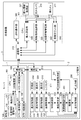
- FIG. 15 is a block diagram showing a hardware configuration of the sales floor device 3 in the product recognition system of FIG.
- the sales floor device 3 includes a CPU 301, a ROM 302, a RAM 303, a bus 304, an input / output interface 305, a ceiling camera 310, a shelf camera 311, a communication unit 315, and an information terminal 9.
- the CPU 301, ROM 302, RAM 303, bus 304, input / output interface 305, and communication unit 315 of the sales floor apparatus are configured in the same manner as those of the server 1 shown in FIG.
- the ceiling camera 310 is connected to the network by a USB (Universal Serial Bus) cable.
- the shelf camera 311 may employ a camera capable of capturing a wide angle, such as a fisheye camera. Further, the shelf camera 311 is connected to a network by a USB cable.
- the information terminal 9 is an information device such as a smartphone or a tablet that includes the remote control unit 390, the display unit 391, and the like.
- the remote operation unit 390 has a function of eliminating an error state such as a system processing abnormality by remote operation.
- the display unit includes a screen for displaying an error state, a moving object Mo, and the like.
- the information terminal 9 includes a voice generation unit (not shown) that notifies an error state.
- an error state in the store for example, there are a case where the ceiling camera 310 cannot recognize the number of books taken from the shelf or a case where an unsettled book is taken out of the store.
- the server 1 includes an error display unit 151 that displays such an error and an error release unit 152 that cancels the error state.
- the cash register terminal 2 is connected to the sales floor device 3 via the network N.
- the cash register terminal 2 is configured in the same manner as the cash register terminal of the first embodiment shown in FIG. Therefore, the cash register terminal 2 according to the second embodiment includes a CPU 201, a ROM 202, a RAM 203, a bus 204, an input / output interface 205, an output unit 206, an input unit 207, an illumination unit 208, a light shielding unit 209, A presentation unit 210, a cash register camera 211, a storage unit 212, a communication unit 213, and a drive 214 are provided.
- the registration camera 211 captures an image of a book placed in the predetermined area A, and outputs a captured image obtained as a result to the image acquisition unit 232 in the CPU 201 as an object captured image.
- the registration camera 211 can capture images at a wide angle like a fisheye camera, or when the registration camera 211 specializes in imaging only the spine of a book, only one registration camera 211 may be provided.
- the CPU 101 of the server 1 includes an error determination unit 150.
- a product DB 131 and a location information management DB 132 are provided in one area of the storage unit 108 of the server 1.
- the product DB 131 is a DB (Data Base) that stores information such as book names, prices, author names, and publishers related to books.
- the position information management DB 132 manages the position of the moving object Mo.
- the CPU 201 of the cash register terminal 2 includes a light emission control unit 228, a light shielding control unit 229, a presentation control unit 230, an image acquisition unit 232, an object recognition unit 233, and a product identification unit 235.
- the sale restriction product determination unit 236, the settlement unit 237, and the display control unit 238 function.
- the light emission control unit 228 performs control to switch between a state in which the illumination unit 208 emits light at the timing when the book is imaged and a state in which light is not emitted at the timing at which the book is not imaged, and a situation in which a book placed in the predetermined area A is recognized Control to switch the emission color.
- the light-shielding control unit 229 performs control to switch between an opaque state at the timing when the light-shielding unit 209 provided in the surrounding unit 270 captures a book placed in the predetermined area A and a transparent state at a timing when the book is not captured.
- the presentation control unit 230 performs control so that the presentation unit 210 changes the emission color that presents the state of the cash register terminal 2.
- the image acquisition unit 232 acquires data of an object image captured by the registration camera 211 with the object placed in the predetermined area A.
- the object recognition unit 233 recognizes the presence of an object placed in the predetermined area A using the above-described predetermined image recognition method.
- the product specifying unit 235 lists the product candidates for the objects whose presence is recognized by the object recognition unit 233 by an image processing method such as specific object recognition, general object recognition, character recognition, or deep learning.
- the listed product candidates are referred to as “product candidate list S”.
- the product specifying unit 235 exhibits the verification function and specifies the product with high accuracy.
- the verification function lists the “product candidate list P” by an algorithm different from the method for listing the product candidates. When the results of the product candidate lists S and P are matched to exceed a predetermined threshold, the product is specified.
- a method for listing up the “product candidate list” for example, it is realized by a method of matching image information of an object obtained from an object whose existence has been recognized with image information held in the DB information holding unit 241 or the memory. May be. That is, if the feature information of both images match (exceeds a threshold value), the object whose existence is recognized by the object recognition unit 233 is a product registered in the DB information holding unit 241, and therefore the product specifying unit 235 The product is registered in the DB information holding unit 241.
- the sale restricted product determination unit 236 determines whether or not the product specified by the product specifying unit 235 is a sale restricted product based on the determination information and presents it.
- a trade-restricted product is, for example, a book whose sales are restricted to shoppers below a certain age. When a store clerk sells a book, the store clerk who saw the shopper can check the age of the shopper and determine whether or not to sell the book.
- this system that employs automatic checkout which is not face-to-face sales, requires a mechanism that allows the store clerk to check the age of the shopper.
- the cashier terminal 2 that has identified the trade-restricted product presents that it is a trade-restricted product, and interrupts the checkout process.
- the store clerk who received the error state confirms the age of the shopper by operating the error display unit 151, operates the cash register terminal 2, and releases the restricted state. Thereby, the settlement process is resumed.
- the cash register terminal 2 includes a cash register camera 211 that captures the shopper's face and hands, etc., and by restricting the shopper's age to a shopper who is determined to have not reached a predetermined age May not be sold.
- the sale restricted product determination unit 236 identifies sale restricted products such as age-restricted books from the information of the DB management unit 141 of the server 1.
- the trade-restricted product determination unit 236 may restrict the trade by associating it with the shopper information obtained for personal authentication. If it is determined that the book is a sale-restricted product, the display unit D presents that it is a sale-restricted product.
- the settlement unit 237 calculates the total amount of the books identified by the product identification unit 235 and made available for sale by the trade-restricted product determination unit 236. For example, the settlement unit 237 reads the price of the book placed in the predetermined area A from the DB information holding unit 241, adds it, displays it on the display unit D (FIG. 6), and performs settlement.
- the display control unit 238 performs control to display the title and price of the book imaged by the cashier camera 211 of the cashier terminal 2 and settled by the settlement unit 237 to the purchaser and the store clerk.
- a personal authentication unit 320 In the CPU 301 of the sales floor device 3, as shown in FIG. 16, a personal authentication unit 320, a moving object tracking unit 330, a location information management unit 340, a book number counting unit 350, a basket product recognition unit 370, and a trade restriction
- the product determination unit 380 functions.
- the personal authentication unit 320 includes a personal information acquisition unit 321.
- the personal authentication unit 320 personally identifies who is the shopper registered in the DB management unit 141 of the server 1 from the shopper's personal information acquired by the personal information acquisition unit 321.
- the personal authentication unit 320 and the personal information acquisition unit 321 may be provided in the cashier terminal 2 as in the first embodiment.
- Personal information here includes not only personally identifiable information such as name, gender, date of birth, address and telephone number, but also financial information such as biometric information such as fingerprints, veins and irises, credit card numbers and bank account numbers.
- Information on privacy such as information on The personal information acquisition unit 321 is provided in the gate 21 installed at the entrance 22, for example.
- a reading device that touches a portable information terminal such as an IC card, a smart phone, or a tablet of a shopper, a reading device that reads biological information such as a fingerprint, a vein, and an iris is adopted.
- personal authentication may be performed from a shopper's image captured by the ceiling camera 310 during shopping.
- the acquired personal information is used for trade restrictions (including cancellation) and purchase analysis.
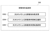
- FIG. 17 is a functional block diagram showing a detailed functional configuration example of the moving object tracking unit 330 provided in the sales floor device 3 of FIG. As shown in FIG. 17, the moving object tracking unit 330 discovers the moving object Mo from the image captured by the ceiling camera 310 and tracks the moving moving object Mo.
- a moving object area defining unit 3304 using a ceiling camera and a moving object area tracking unit 3305 using a ceiling camera are provided.
- the moving object tracking unit 330 by the ceiling camera is connected to the ceiling camera 310 through a USB cable, a network N, or the like. Therefore, the ceiling camera 310 is linked with other ceiling cameras 310, personal computers, and the like.
- the moving object discovery unit 3302 by the ceiling camera estimates the state of the moving object Mo using a state space model (Bayesian filter or the like) based on the captured image captured by the ceiling camera 310, and discovers the moving object Mo. An ID that can be uniquely identified is assigned.
- a state space model Boyesian filter or the like
- the ceiling camera 310 may acquire position information with high accuracy by acquiring height information of the moving object Mo using a distance sensor or the like.
- the moving object area defining unit 3304 by the ceiling camera updates the position information of the area of the moving object Mo after moving. Since the moving object Mo continues to move, the moving region changes within the range imaged by one ceiling camera 310 and moves within the range imaged by another ceiling camera 310. Each time the moving object Mo moves, a moving object region is defined, and position information of each moving object region such as a position information management DB 132 that manages position information and a memory is updated.
- the moving object area tracking unit 3305 estimates the position of the moving object area and continues to track the moving object area of the moving object Mo.
- FIG. 18 is a functional block diagram illustrating a detailed functional configuration example of the location information management unit 340 provided in the sales floor device 3 of FIG.
- the position information management unit 340 includes an inter-camera information transfer unit 341, a position definition unit 342 for each camera, and a moving object display unit 343.
- the inter-camera information transfer unit 341 shares the image information captured by each ceiling camera 310 with the image information captured by the other ceiling cameras 310, whereby the captured image of the ceiling camera 310 where the moving object Mo is present. Even if the image is picked up by another ceiling camera 310, the moving object region can be continuously tracked.
- the inter-camera information transfer unit 341 exchanges information between the ceiling cameras 310 on the storage unit 108, including the product DB 131, through the server 1 that supervises information obtained by being captured by the ceiling camera 310.
- the inter-camera information transfer unit 341 receives an image captured by each ceiling camera 310 without passing through the server 1, for example, by P2P between each ceiling camera 310. You may make it pass.
- the position definition unit 342 of each camera defines position information indicating where in the store each ceiling camera 310 is imaged.
- the position definition unit 342 of each camera grasps where in the store the moving object imaged by the separate ceiling camera 310 by the inter-camera information transfer unit 341 is located.
- the position definition unit 342 of each camera synthesizes the captured images of the ceiling cameras 310 and creates one store map. Further, the position definition unit 342 of each camera replaces the coordinates of the ceiling camera 310 and the shelf camera 311 with the coordinates on the store map. Further, the position definition unit 342 of each camera corrects the captured image captured by each ceiling camera 310 so as to be a captured image that faces the floor in the store by calculation through perspective transformation.
- the position information management unit 340 accurately corrects the distorted captured image and accurately recognizes the moving object Mo by obtaining the height information by mounting the distance sensor on the ceiling camera 310. can do.
- the moving object display unit 343 displays the moving object Mo in the store 30 based on the position information captured by the position definition unit 342 of each camera.
- the moving object display unit 343 may be employed as the information terminal 9 held by the store clerk Mt, the screen of the backyard of the store, or the like.
- FIG. 19 is a functional block diagram showing a detailed functional configuration example of the book number counting unit 350 provided in the sales floor device 3 of FIG.
- the book number counting unit 350 includes a book number recognition unit 351, a person-to-book number linking unit 352, a book number non-specific determination unit 353, a book number management unit 354 associated with a person, and a moving object area transfer recognition unit 355 using a ceiling camera. And a book number recognition unit 356 delivered by the ceiling camera.
- the book number recognition unit 351 recognizes the number of books taken by the moving object Mo from the shelf and the number of books returned to the shelf from the captured image captured by the ceiling camera 310.
- the number-of-books recognition unit 351 detects the movement of the moving object area into the shelf by providing an “object entry detection line” or the like in the captured image, and the moving object Mo is moved from the captured image at the time of detection to the shelf. Define the area of the object taken from inside and the object returned to the shelf. The number of the object areas is recognized as the number of books. If the ceiling camera 310 is equipped with a zoom function, the book number recognition unit 351 may recognize the number of books after the ceiling camera zooms in consideration of the distance between the ceiling camera 310 and the moving object Mo. Good.
- the book number recognition unit 351 may recognize the number of books taken by the moving object Mo from the shelf and the number of books returned to the shelf by the shelf camera 311, and the shopper can recognize the number of books from the combination of the ceiling camera 310 and the shelf camera 311.
- the number of books taken from the shelf and the number of books returned to the shelf may be recognized.
- the shelf camera 311 at that time may be a camera that can capture images over a wide range.
- the person and book number association unit 352 associates the number of books recognized by the book number recognition unit 351 with the person who took the book.
- the book number non-specific determination unit 353 associates that the number of books could not be recognized with the moving object Mo.
- the book number management unit 354 associated with the person always manages the book number count list associated with the ID of the moving object Mo by utilizing the position information management DB 132 or the like.
- the number of books acquired is added.
- the number of returned books is subtracted.
- the transfer recognition unit 355 between the moving object areas by the ceiling camera delivers the book number information associated with each moving object Mo to the transferred moving object Mo.
- the transfer recognition unit 355 between the moving object areas by the ceiling camera may analyze the movement of the person using an object recognition method such as deep learning, and may recognize the transfer. May be recognized, and an overlap between moving object regions (which may include hands) may be recognized.
- the moving object area transfer recognition unit 355 using the ceiling camera may use the shelf camera 311 instead of the ceiling camera 310.
- the shelf camera 311 at that time may be a camera that can capture images over a wide range.
- the book number recognition unit 356 delivered by the ceiling camera recognizes the number of books when the books are delivered between the moving object area bodies.
- the book number recognition unit 356 delivered by the ceiling camera recognizes the number of books from the captured image when the delivery is recognized.
- the book number recognizing unit 356 delivered by the ceiling camera may include a ceiling camera having a zoom function to zoom in on a place estimated to have been delivered and recognize the number of books.
- the book number recognition unit 356 delivered by the ceiling camera may recognize the number of books by using a shelf camera 311 that can image a wide range instead of the ceiling camera 310.
- the book number recognition unit 356 delivered by the ceiling camera links each moving object Mo identified by the moving object area delivery recognition unit 355 by the ceiling camera and the number of books recognized here, Update the number list.
- FIG. 20 is a flowchart illustrating book settlement processing in the second embodiment.
- step S201 when the shopper (moving object Mo) enters the store from the entrance 22 of the store (FIG. 12), the ceiling camera 310 installed in the vicinity of the entrance 22 starts imaging the shopper. As the shopper advances through the passage 24, the back side ceiling camera 310 images the shopper. In this way, the plurality of ceiling cameras 310 constantly image the shopper.
- a gate 21 may be provided in the vicinity of the entrance 22. When the gate 21 is provided at the entrance / exit 22, the gate 21 is always closed, but is opened when the shopper enters the store and is closed after entering the store.
- the personal authentication unit 320 may perform personal authentication of the shopper and acquire the shopper's personal information.
- step S202 the moving object finding unit 3302 using the ceiling camera defines only the shopper's area (moving object area) imaged in step S201, thereby defining the moving object Mo and assigning the ID to the moving object Mo. Numbering is performed, and the location information in the store associated with the ID is registered in the location information management DB 132 and the RAM 303 of the sales floor device 3.
- step S203 when the moving object area defining unit 3304 by the ceiling camera moves within the range imaged by the ceiling camera 310, the position of the area of the moving object Mo after the movement is defined again.
- the position information is managed by a position information management DB 132 that manages the position of a person, a memory, and the like, and updated for each area definition. This defined position is recognized even at a position captured by another ceiling camera 310.
- step S204 the moving object area tracking unit 3305 using the ceiling camera estimates the position of the moving object area and keeps track of the moving object Mo based on the fact that the shopper moves along the passage 24 aiming for the book he / she wants to purchase.
- step S201 the moving object Mo is always imaged.
- step S202 an ID is assigned to the moving object Mo.
- step S203 the position information of the area of the moving object Mo after the movement is updated, and further, an inter-camera information transfer unit. Since the position information is exchanged by 341, even if the moving object Mo moves through the passage 24 and is captured by a different ceiling camera 310, the moving object region tracking unit 3305 by the ceiling camera continues to track the moving object Mo. Can do.
- step S205 the book number recognition unit 351 recognizes the number of books taken from the shelf and the number of books returned to the shelf by the moving object Mo assigned with the ID.
- step S205 if the number of books taken cannot be counted, a book number non-specific determination unit (not shown) outputs an error.
- step S206 the person and book number association unit 362 associates the book number recognized (counted) in step S205 with the moving object Mo. Therefore, the book number recognition unit 351 recognizes how many books the shopper uniquely identified has taken.
- step S207 the book number management unit 363 associated with the person continues to manage the number of books associated with the person using the DB management unit 141 of the server 1. Therefore, even when a book taken from the shelf by the shopper is returned to the shelf, the book number management unit 363 associated with the person recognizes the number of books held by the shopper.
- the shopper When the shopper finishes taking the book, the shopper goes to the cashier terminal 2 and places the book in the predetermined area A of the cashier terminal 2. As shown in FIG. 13, the book is placed such that the back cover is copied to at least one camera 211 of the cash register terminal 2. Then, the shopper depresses a button that is the input unit 207 provided in the cash register terminal 2. The cashier terminal 2 specifies a product by using a press of this button as a trigger. The product specification is performed by specifying the title of the book from the cover or spine of the book using character recognition and image recognition techniques.
- step S210 whether the product identification unit 235 of the cash register terminal 2 matches the book number information associated with the moving object Mo recognized in step S207 and the book number information of the book placed in the predetermined area A of the cash register terminal 2. Verify whether. A specific flow of this verification will be described later with reference to FIG. If the book number information associated with the moving object Mo and the book number information of the book placed in the predetermined area A of the cash register terminal 2 do not match, an error is displayed on the error display unit 151 and cannot be settled. In addition, if the user tries to leave the store in that state, the error display unit 151 installed in the vicinity of the entrance / exit 22 issues a warning by sound, light, or the like. When the gate 21 is installed, the closed state is maintained.
- step S ⁇ b> 210 the sale restricted product determination unit 236 may determine whether or not the book placed on the cashier terminal 2 corresponds to the presence or absence of restriction. By acquiring personal information in advance at any timing up to step S207 (including before step S201), the trade-restricted merchandise determination unit 236 allows the shopper who cannot purchase a restricted book to purchase.
- the error display unit 151 displays an error.
- step S211 the settlement unit 237 of the cash register terminal 2 settles the total amount of books placed in the predetermined area A. That is, as described in the first embodiment, information such as the price of a book is obtained by the product specifying unit 235, and the total amount is calculated. The shopper completes the payment by paying with a credit card or electronic money. When the payment is completed, the DB management unit 141 updates the book count list associated with the person to a “settled” state.
- the take-out detection unit Is detected, and the error display unit 151 near the entrance / exit 22 and the presentation unit 210 of the cash register terminal 2 present it with sound, light, or the like.
- the gate 21 is installed, the gate 21 is kept closed, and the shopper cannot leave the store.
- the error display unit 151 or the like may issue a warning by sound or light. Thereby, shoplifting can be prevented.
- the error display unit 151 and the presentation unit 210 of the cash register terminal 2 may emit light in different colors depending on the error state.
- FIG. 21 is a flowchart for explaining verification of the book number information of books and the number of books to be settled in step S210 of FIG.
- step S221 when the reading start button of the input unit 207 of the cash register terminal 2 is pressed, the image acquisition unit 232 of the cash register terminal 2 acquires the object captured image placed in the predetermined area A of the cash register terminal 2, and then exists.
- the product specification unit 235 specifies which product is the product and also recognizes the number of products.
- the person of the book number counting unit 350 of the sales floor device 3 and the book number linking unit 362 inquire about the number of books of the book placed on the cash register terminal 2 from the ID of the moving object Mo.
- step S223 the product specifying unit 235 determines whether the number of books placed on the cash register terminal 2 matches the number of books counted by the book number management unit associated with the person. If they match (YES), the payment can be made. If the number of books placed on the cash register terminal 2 and the number of books counted by the book number management unit linked to the person do not match (NO), the error display unit 151 of the cash register terminal 2 displays an error, Issue a warning. Note that if the user tries to leave the store in this state, the error display unit 151 near the entrance / exit 22 issues a warning by sound or light. When the gate 21 is installed, the gate 21 is kept closed and the shopper cannot leave the store. Thereby, shoplifting can be prevented.
- FIG. 22 is a diagram illustrating a layout example of a supermarket that employs the product recognition system of the third embodiment.
- the product recognition system of Embodiment 3 is a system applied to a store 30 such as a supermarket as shown in FIG.
- the store 30 has a sales floor from the entrance 31 to the exit 32.
- a plurality of shelf racks 33 for displaying products are installed in the sales floor.
- a passage 34 is formed between the two shelf racks 33 facing each other.
- a settlement area 35 is provided in front of the exit 32.
- a plurality of cash register stands 36 are installed in the settlement area 35.
- the cash register 36 includes n payment machines 4.
- the cashier terminal 2 as employed in the first and second embodiments is not provided.
- a basket that is grasped (discovered / tracked) on the system is handled as the moving object Mo.
- the shopper enters the store from the entrance 31, takes the basket, and proceeds through the passage 34.
- the shopper picks up the goods on the shelf, puts them in the baskets, and proceeds through the passage 34.
- the shopper proceeds to the checkout area 35 and checks out with the checkout machine 4.
- the store clerk Mt looks around in the passage 34, the payment area 35, and the like.
- the salesclerk Mt has an information terminal 9a.
- the information terminal 9a is a portable information processing terminal such as a smartphone, and includes a screen for displaying the in-store state. In FIG. 22, the backyard of the store 30 and the outside of the store 30 are drawn, not inside the store 30, inside the diagram drawn in a cloud shape.
- the server 1 (FIG. 5) is installed.
- the store clerk Mt monitors the inside of the store 30 through a large monitor screen (not shown) or the information terminal 9b.
- a large monitor screen not shown
- the information terminal 9b When it is not necessary to distinguish between the information terminal 9a and the information terminal 9b, these are collectively referred to as “information terminal 9”.
- a plurality of ceiling cameras 310 are installed separately on the ceiling above the passage 34, the shelf rack 33, and other arbitrary positions in the store 30, respectively.
- the ceiling camera 310 images the passage 34, the shelf rack 33, and other predetermined areas below the passage 34 and the shelf rack 33. That is, when the moving object Mo enters, the ceiling camera 310 images the predetermined area including the moving moving body Mo as a subject.
- a shelf camera 311 is installed as an example of a sensing device in each of a plurality of locations of each shelf in each shelf rack 33.
- the shelf camera 311 images a shelf, a product in the shelf, and other predetermined areas. Further, the shelf camera 311 captures the hand or the object in the shelf as an object captured image when a shopper's hand or the like enters a predetermined area in the shelf or an object is taken from the shelf.
- a basket camera 312 (not shown in FIG. 22) may be attached to each basket as an example of a sensing device. In that case, one or more basket cameras 312 of the sales floor device 3 are installed in the baskets, and always image an object placed in the baskets.
- the basket camera 312 is installed so that the inside of the basket can be imaged without a blind spot.
- the basket camera 312 images at least a part having a feature such as a front surface of an object placed in the basket.
- the basket camera 312 is linked with the ceiling camera 310 and the shelf camera 311 through the network N.
- the sales floor device 3 can share both the captured images captured by the basket camera 312 and the captured images of the objects captured by the ceiling camera 310 and the shelf camera 311. By this sharing, it is possible to improve the accuracy of specifying a product from the object imaged in the captured image.
- the product recognition system of the third embodiment has a function of continuously tracking the moving object Mo even when the moving object Mo imaged by the ceiling camera 310 moves.
- the information processing system according to the third embodiment has a function of identifying which product is an object taken from the shelf rack 33 from a captured image captured by the shelf camera 311.
- the product recognition system of the third embodiment may have a function of identifying which product is an object placed in the basket from a captured image captured by the basket camera 312.
- the product recognition system according to the third embodiment has a function of specifying which product the object in the shelf is and further automatically adjusting the product in the checkout machine 4. At the time of this automatic settlement, information on the product linked to the moving object Mo in the settlement machine 4 is read, and automatic settlement is possible.
- the checkout machine 4 includes functions necessary for completing the shopping, such as a total amount of purchased products, a score, a display of details, a display of sale restricted product determination, a settlement function, and the like.
- the ceiling camera 310, the shelf camera 311 and the basket camera 312 are incorporated in the sales floor device 3 as shown in FIGS.
- the sales floor device 3 includes a function for specifying a product from a captured image captured by the ceiling camera 310, the shelf camera 311 and the like, and a function for discovering and tracking the moving object Mo.
- This sales floor device 3 is incorporated in a product recognition system as shown in FIG.
- FIG. 23 is a configuration diagram illustrating a configuration of the product recognition system according to the third embodiment.
- the product recognition system according to the third embodiment includes a server 1, a sales floor device 3, and a payment machine 4.
- a checkout machine 4 is provided instead of the cash register terminal 2 described in the first and second embodiments.
- FIG. 23 only one server 1 and sales floor apparatus 3 are drawn, but there may actually be a plurality of servers. In the following, when it is not necessary to distinguish the settlement machines 4 individually, these are collectively referred to as “settlement machine 4”.
- the server 1 and the sales floor device 3 are connected to each other via a network N such as the Internet.
- the server 1 is configured similarly to the server 1 (FIG. 5) of the first embodiment.
- FIG. 24 is a block diagram showing a hardware configuration of the sales floor device 3 in the product recognition system of FIG.
- the sales floor device 3 includes a CPU 301, a ROM 302, a RAM 303, a bus 304, an input / output interface 305, a ceiling camera 310, a shelf camera 311, a basket camera 312, a communication unit 315, and an information terminal 9.
- a CPU 301 a central processing unit 303
- the CPU 301, ROM 302, RAM 303, bus 304, input / output interface 305, and communication unit 315 of the sales floor device 3 are configured in the same manner as those of the server 1 shown in FIG.
- the ceiling camera 310, the shelf camera 311, the communication unit 315, and the information terminal 9 of the sales floor device 3 are configured in the same manner as those of the sales floor device 3 (FIG. 15) described in the second embodiment.
- FIG. 25 is a functional block diagram showing an example of the functional configuration of the server 1 of FIG. 5, the sales floor device 3 of FIG.
- the server 1 includes a CPU 101, a storage unit 108, a communication unit 109, an error display unit 151, and an error release unit 152. These are configured similarly to the second embodiment shown in FIG.
- a personal authentication unit 320 In the CPU 301 of the sales floor apparatus 3, as shown in FIG. 25, a personal authentication unit 320, a moving object tracking unit 330, a position information management unit 340, a shelf product recognition unit 360, a basket product recognition unit 370, The restricted product determination unit 380 functions.
- the personal authentication unit 320 includes a personal information acquisition unit 321.
- the personal authentication unit 320 and the personal information acquisition unit 321 are configured in the same manner as in the second embodiment shown in FIG.
- FIG. 26 is a functional block diagram illustrating a detailed functional configuration example of the moving object tracking unit 330 provided in the sales floor device 3 of FIG.
- the moving object tracking unit 330 includes a moving object finding unit 3302 using a ceiling camera, a car finding unit 3303 using a ceiling camera, a car region defining unit 3306 using a ceiling camera, and a car region tracking unit using a ceiling camera. 3307, an inter-carriage transfer recognition unit 3310 using a ceiling camera, a grouping unit 3308, an object recognition unit 3312 transferred using a ceiling camera, and a product specifying unit 3313 transferred using a ceiling camera.
- the moving object tracking unit 330 according to the third embodiment handles a basket grasped (discovered / tracked) on the system as the moving object Mo, unlike the second embodiment in which the shopper is treated as a moving object.
- the moving object tracking unit 330 is connected to the ceiling camera 310 through a USB cable, a network N, or the like. Therefore, the ceiling camera 310 is linked with other ceiling cameras 310, personal computers, and the like.
- the moving object finding unit 3302 using the ceiling camera finds objects (shoppers, baskets, carts, etc.) that move in the store using a state space model (Bayesian filter or the like) based on the image taken by the ceiling camera 310. .
- the car discovery unit 3303 using the ceiling camera finds a basket (moving object Mo) from the objects moving in the store 30 discovered by the moving object discovery unit 3302, and assigns an individual ID to the moving object Mo. .
- the ID of the moving object Mo is kept used until a predetermined timing such as closing or completion of payment.
- a method for discovering the moving object Mo from the object moving in the store 30 for example, one or more markers holding information that can be individually identified are attached to each cage, and the cage finding unit 3303 by the ceiling camera is used. Finds the moving object Mo using this marker as a landmark.
- the marker is not limited as long as it can identify the moving object Mo, such as a two-dimensional code or a characteristic shape.
- the car discovery unit 3303 using the ceiling camera may use information unique to the car such as color information and shape information of the car. At this time, the car discovery unit 3303 using the ceiling camera can find the moving object Mo since the color and shape of the car can be distinguished from the floor surface.
- thermography or the like may be used by lowering the temperature of the cage.
- the cage finding unit 3303 by the ceiling camera finds the moving object Mo that has been lowered in temperature from the temperature difference from the area other than the cages.
- harmless gas may be generated from the baskets and thermography or the like may be used.
- the car discovery unit 3303 by the ceiling camera detects a temperature change accompanying the generation of harmless gas generated from the car by thermography or the like, and discovers the moving object Mo.
- the car discovery unit 3303 by the ceiling camera detects the moving object Mo by detecting the sound generated from the car.
- a sensor that can apply the invisible paint to the basket and recognize the invisible paint may be used.
- the car discovery unit 3303 by the ceiling camera discovers the moving object Mo by the sensor recognizing the invisible paint applied to the car.
- the ceiling camera 310 may irradiate the baskets with visible light, infrared light, or the like. At this time, the car discovery unit 3303 by the ceiling camera discovers the moving object Mo by receiving the visible light or the reflected light of the infrared rays irradiated on the car.
- the car area defining unit 3306 by the ceiling camera defines a certain range in the captured image as the area of the moving object Mo in the periphery of the moving object Mo discovered by the car finding unit 3303 by the ceiling camera.
- a certain range is defined as the area of the moving object Mo from the attached position where the marker is attached.
- the cage area defining unit 3306 by the ceiling camera has its own position in the area of the moving object Mo even if the ceiling camera 310 cannot capture all the markers. Since the information is held, the area of the moving object Mo may be defined from one or more markers.
- the cage area defining unit 3306 by the ceiling camera may use a technique that complements the technique for defining the above-described cage area.
- a technique that complements the technique for defining the above-described cage area in the case where the temperature of the cage is lowered as described above, a low temperature region is defined as a region of the moving object Mo from thermography and image recognition.
- thermography thermography
- temperature change due to gas generation is detected by thermography etc., and temperature change is also made full use of image recognition technology.
- the area where the error occurred is defined as the area of the moving object Mo.
- the cage area defining unit 3306 by the ceiling camera estimates the edge of the basket from the application position of the paint, A region closed by the edge is defined as a region of the moving object Mo.
- the cage area defining unit 3306 by the ceiling camera irradiates the area of the moving object Mo from the measurement result of the reflection when the ceiling camera 310 emits visible light, infrared light, or the like as described above. Define.
- the cage area tracking unit 3307 by the ceiling camera estimates (defines) the position of the area of the moving object Mo.
- the cage area tracking unit 3307 by the ceiling camera keeps track of the position information by tracking the moving object Mo with the same ID from the time when the moving object Mo is found until a predetermined time such as closing or completion of payment.
- the cage area tracking unit 3307 using the ceiling camera keeps track of the basket area in the captured image at all times in cooperation with many ceiling cameras 310.
- the cage area tracking unit 3307 by the ceiling camera can take over a captured image captured by a certain ceiling camera 310 to a captured image captured by an adjacent ceiling camera. To do.
- the cage area tracking unit 3307 by the ceiling camera stores the positional information of the moving object Mo being tracked in the positional information management DB 132 or the storage unit 108 of the server 1.
- a marker having information for specifying the moving object Mo is attached to each cage, and the ceiling camera 310 includes the moving object including the marker.
- Image Mo The cage area tracking unit 3307 using the ceiling camera discovers the moving object Mo by extracting a marker from the captured image, and acquires position information.
- the cage area tracking unit 3307 by the ceiling camera discovers the marker from the captured image and acquires the positional information of the moving object Mo, so that the moving object Mo can be continuously tracked even if the moving object Mo moves.
- the cage area tracking unit 3307 using the ceiling camera tracks the moving object Mo using other object tracking techniques such as Bayesian filter, fast Fourier transform, and TLD as another method for tracking the moving object Mo. Also good.
- the cage area tracking unit 3307 using the ceiling camera estimates that the moving object Mo that has acquired the same feature data is the same moving object Mo based on the feature data such as the color and shape of the cage. The moving object Mo may be tracked. At this time, the cage area tracking unit 3307 using the ceiling camera continues to collect feature data of the tracking target.
- the moving object Mo that is not directly facing the ceiling camera 310 is imaged at an angle (from an oblique direction), and thus there is a possibility that the position information cannot be acquired accurately. Therefore, it is conceivable that the captured image is imaged as if it is directly facing by applying correction by calibration. However, even if such correction is applied, the position information of the moving object Mo may not be acquired with high accuracy. Therefore, the cage area tracking unit 3307 using the ceiling camera acquires high-precision position information by acquiring the height information of the moving object Mo using a distance sensor or the like. In this way, the cage area tracking unit 3307 by the ceiling camera may continue to track the moving object Mo.
- the grouping unit 3308 may link a plurality of baskets (moving objects Mo). By being linked in this way, the settlement machine 4 installed in the settlement area 35 can collectively settle the product list of each moving object Mo.
- the inter-car area transfer recognition unit 3310 by the ceiling camera recognizes by the ceiling camera 310 or the like that an object has been transferred (moved in or out) between the moving objects Mo.
- the inter-car region transfer recognition unit 3310 by the ceiling camera may recognize the transfer by recognizing the overlap between the regions of the moving object Mo.
- the inter-car area transfer recognition unit 3310 by the ceiling camera identifies the moving object Mo to which the object has been transferred, and reads a product list associated with the ID of each moving object Mo.
- the object recognition unit 3312 delivered by the ceiling camera defines an object region from the captured image at the time when the delivery is recognized.
- the object recognizing unit 3312 delivered by the ceiling camera may make the ceiling camera 310 a zoomable camera, zoom in on a place estimated to have been delivered, and define the object region.
- the product identification unit 3313 delivered by the ceiling camera identifies which product is the product in the product list associated with the read moving object Mo from the image after the object area is defined,
- the moving object Mo identified by the inter-car area transfer recognition unit 3310 by the ceiling camera is associated with the product identified by the delivery, and the list of products associated with each moving object Mo is updated.
- the object recognition unit 3312 delivered by the ceiling camera and the product identification unit 3313 delivered by the ceiling camera may be realized by a shelf camera 311 that can capture a wide range, instead of the ceiling camera 310.
- the location information management unit 340 is configured in the same manner as the location information management unit 340 described in the second embodiment. That is, the position information management unit 340 includes an inter-camera information transfer unit 341, a position definition unit 342 for each camera, and a moving object display unit 343, as shown in FIG.
- FIG. 27 is a functional block diagram showing a detailed functional configuration of the shelf commodity recognition unit 360 provided in the sales floor device 3 of FIG.
- the shelf product recognition unit 360 includes an object recognition unit 3602 using a shelf camera, a product specifying unit 3603 using a shelf camera, a basket and product association unit 3605, a product list management unit 3607 associated with the basket, and an object entry / exit using a shelf camera.
- a detection unit 3608, a product non-specific determination unit 3609, a label recognition unit 3610, a discount sticker recognition unit 3611, and a basket entry / exit detection unit 3612 using a shelf camera or a ceiling camera are provided.
- the shelf product recognition unit 360 is linked with other cameras, personal computers, and the like through the shelf camera 311 and a USB cable or a network.
- the object recognition unit 3602 by the shelf camera compares the images before and after the image in which the object is taken from the shelf or the object is placed in the shelf (returned), and the image region that is the target for product identification is compared.
- Define (area definition) That is, the object recognition unit 3602 by the shelf camera captures an object captured image before the object is taken from the shelf or placed on the shelf, and an object captured after the object is taken from the shelf or placed on the shelf.
- the object captured images before and after the image change are compared, and the changed image region is specified.
- the object recognition unit 3602 by the shelf camera confirms the change in each of the RGB data when specifying the image area.
- the object recognition unit 3602 by the shelf camera is triggered by the object entry / exit detection unit, and the object captured image before the object is taken from the shelf or placed on the shelf and the object taken from the shelf or the shelf
- the object region may be defined from only one object captured image using a method different from the comparison before and after the change of the object captured image after being placed on the object. Since the color data of the object is the same, the object recognition unit 3602 by the shelf camera defines the region also by using the shadow of the object so that it is not determined that there is no change even if there is a change such as entry / exit. May be. Information on the recognized object region is delivered to the product specifying unit 3603 by the shelf camera.
- the product specifying unit 3603 by the shelf camera specifies which product the object in the shelf recognized by the object recognition unit 3602 by the shelf camera is.
- the product specifying unit 3603 using the shelf camera lists product candidates by using an image processing method such as specific object recognition, general object recognition, or deep learning.
- the listed product candidates are referred to as “product candidate list S”. Thereafter, the product specifying unit 3603 using the shelf camera specifies the product with high accuracy by exhibiting the verification function.
- the verification function lists the “product candidate list P” by an algorithm different from the method for listing the product candidates.
- the product is specified.
- a method for listing up the “product candidate list” for example, it may be realized by a method of matching image information of an object obtained from an object whose existence has been recognized with image information stored in the product DB 131 or a memory. . That is, if the feature information of both images match (exceeds a threshold value), the object recognized by the object recognition unit 3602 by the shelf camera is a product registered in the product DB 131, so the product specification by the shelf camera is specified.
- the unit 3603 identifies the product registered in the product DB 131.
- a product candidate is created by deep learning, and then a verification function is performed to identify the product with high accuracy.
- the product specifying unit 3603 using the shelf camera does not specify the product in one frame of the captured image captured by the shelf camera 311, and also uses the captured image captured by the ceiling camera 310 to specify the product over a plurality of captured images. May be. At that time, the product specifying unit 3603 using the shelf camera gives a percentage to the product candidate, adds the percentage based on information such as purchase history, time, place, and person's preference, and exceeds a certain threshold. Identify the product when
- the basket and product association unit 3605 associates the product information of the product identified by the product identification unit 3603 with the shelf camera and the moving object Mo. As a premise, if there is only one moving object Mo in a predetermined area captured by one shelf camera 311, by specifying the ID of the car moving object Mo, Product information can be linked. At this time, the basket and product associating unit 356 identifies the ID of the moving object Mo using position information associated with a marker or the like attached to the moving object Mo.
- a cage entrance / exit detection unit by a shelf camera or a ceiling camera described later will enter the moving object Mo.
- the moving object Mo containing the object taken from the shelf is specified, and the moving object Mo is associated with the product information.
- at least one shelf camera 311 or at least one or more The basket camera 312 detects entering / exiting the moving object Mo, specifies the moving object Mo, and associates the specified moving object Mo with the product information.
- the product list management unit 3607 associated with the basket continues to manage a product list that associates the moving object Mo with the identified product until the settlement.
- the product list management unit 3607 associated with the basket always manages the list of products associated with the ID of the moving object Mo using the position information management DB 132 or the like.
- the product list management unit 3607 associated with the basket adds the number of acquired products.
- the product list management unit 3607 associated with the basket subtracts the number of returned products.
- the object entry / exit detection unit 3608 by the shelf camera can serve as a trigger for the activation of the object recognition unit 3602 by the shelf camera.
- the object entry / exit detection unit 3608 by the shelf camera detects the entry of the object into the shelf from the change in the image data in the “entry detection area” set in the captured image of each shelf camera 311. Further, the object entry / exit detection unit by the shelf camera also detects that the object has left the area by tracking the entered object in the image.
- the object entry / exit detection unit 3608 using the shelf camera puts a particle filter on the entry detection area in the shelf.
- the particles are again sprinkled in the “entry detection area”. Prepare for the next object.
- the object entry / exit detection unit 3608 using the shelf camera does not scatter particles in the entry detection area related to the area where the object already exists.
- the object entering / exiting detection unit 3608 using the shelf camera determines that the object has a certain likelihood when the ratio of particles having a certain likelihood is greater than or equal to a threshold value, and if particles having a certain likelihood are less than the threshold value. Is determined to be “out of object”.
- the object entry / exit detection unit by the shelf camera detects entry / exit each time a product enters, so that the area of the object as small as possible is estimated once.
- the images before and after the change are stored in the storage unit 108 of the server 1 so that they can be used in the estimation area.
- the object entry / exit detection unit 3608 using the shelf camera may detect the object entry / exit from spectrum (wavelength) data obtained from the captured image of the object, in addition to the above-described example. Furthermore, the object entry / exit detection unit using the shelf camera may detect the object entry / exit using a method such as a weight / pressure sensor, an infrared sensor, or an ethylene gas sensor.
- the product non-specific determination unit 3609 associates that the product cannot be specified by the product specification unit 3603 using the shelf camera with the moving object Mo that has taken the object from the shelf.
- the product specifying unit 3603 by the shelf camera specifies the number of feature points that are similar between an image in which an object is taken from the shelf and an image in which the object is placed on the shelf. For example, the size of the object captured in both images is specified and compared, the color difference is specified and the colors are compared, and it is determined whether or not the two objects are similar. If the number of feature points is small, it is not possible to specify a product and prevent it from being settled by mistake.
- the label recognition unit 3610 recognizes the attached label according to the product specified by the product specification unit 3603 using the shelf camera.
- the label recognizing unit 3610 makes full use of image recognition and character recognition techniques, reads a multidimensional code including characters, barcodes, and the like written on the label, and complements product identification.
- the discount sticker recognition unit 3611 recognizes the pasted discount sticker according to the product specified by the product specification unit 3603 using the shelf camera.
- the discount sticker recognition unit 3611 specifies a discount amount and a discount rate of the discount sticker attached to the product by making full use of image recognition and character recognition techniques.
- the discount sticker recognition unit 3611 is executed during the processing of the product specifying unit.
- the basket entry / exit detection unit 3612 by the shelf camera or the ceiling camera has a moving object Mo in a predetermined area of the shelf camera and the ceiling camera from a marker or the like to which at least one of the shelf camera 311 or the ceiling camera 310 is attached to the basket. Whether the moving object Mo enters or exits is detected.
- the basket entry / exit detection unit 3612 by the shelf camera or the ceiling camera may further detect the entry of the moving object Mo defined by the marker or the like. At this time, the moving object Mo enters the area by comparing the position information of the tracked product with the position information of the entry detection line (such as the edge of the car) of the moving object Mo area.
- the information processing system may further include a basket product recognition unit 370.
- FIG. 28 is a functional block diagram illustrating a detailed functional configuration example of the basket product recognition unit 370 provided in the sales floor device 3 of FIG.
- the basket product recognition unit 370 includes a basket camera detection unit 372, a basket camera object recognition unit 373, a basket camera product identification unit 374, a basket product non-specific determination unit 375, and a basket product label recognition.
- a unit 376 and a basket product discount sticker recognition unit 377 is a basket product recognition unit 377.
- the basket entry / exit detection unit 372 by the basket camera detects the entry of an object such as a shopper's hand into the basket (moving object Mo), thereby activating the object recognition unit 373 by the basket camera.
- the basket entry / exit detection unit 372 by the basket camera detects the entry of an object into the cage from the image change in the “entry detection area” set in the captured image of each basket camera 312.
- the basket entry / exit detection unit 372 by the basket camera also detects that the moving object Mo has left the frame by tracking the object that has entered the frame of the captured image within the frame.
- the basket entry / exit detection unit 372 by the basket camera tracks an object using a particle filter.
- the basket entry / exit detection unit 372 by the basket camera re-spreads particles into the entry detection area after the first object enters and prepares for the next object to enter.
- the basket entry / exit detection unit 372 by the basket camera determines “object entry” when the ratio of particles having a certain likelihood in the predetermined area is equal to or greater than the threshold, and “object exit” when the ratio is less than the threshold. Is determined.
- the basket entry / exit detection unit by the basket camera detects entry / exit each time an object enters / exits so as to estimate the area of the object as small as possible.
- the object recognizing unit 373 by the basket camera compares an image when an object such as a shopper's hand enters the basket (moving object Mo) and an image after exiting the basket (moving object Mo). Then, an image region is defined in order to specify a product of an object taken from the shelf and placed in the basket (moving object Mo) (or returned from the basket (moving object Mo) to the shelf).
- the object recognizing unit 373 by the basket camera confirms the change of the region using the RGB data.
- the object recognition unit 373 using a basket camera may recognize an object from spectrum (wavelength) data obtained from a captured image of the object, a weight sensor, a pressure sensor, an infrared sensor, a methylene gas sensor, or the like.
- the product specifying unit 374 by the basket camera specifies which product is the object placed in the basket.
- the product specifying unit 374 using the basket camera lists product candidates for the objects recognized by the object recognition unit 373 using the basket camera using an image processing method such as specific object recognition, general object recognition, or deep learning.
- the listed product candidates are referred to as “product candidate list S”. Thereafter, the product specifying unit 374 using the basket camera exhibits the verification function and specifies the product with high accuracy.
- the verification function lists the “product candidate list P” using an algorithm different from the method for listing the product candidates.
- the product specifying unit 374 by the basket camera matches the product candidate lists S and P, and specifies a product when a predetermined threshold is exceeded.
- a method of listing product candidates for example, it is realized by a method of matching information of an object captured image obtained from an object whose existence is recognized with image information held in the product DB 131 or the storage unit 108. Also good. That is, if the feature information of both images match, that is, exceeds a threshold value, the object whose presence is recognized by the object recognition unit 373 by the basket camera is identified as a product registered in the product DB 131.
- the product specifying unit 374 using the basket camera may specify the product from the captured images over a plurality of frames without specifying the product in one frame of the captured image. At that time, the product specifying unit 374 by the basket camera gives a percentage to the product candidate, adds the percentage based on information such as purchase history, time, place, and person's preference, and exceeds a certain threshold. Sometimes a product may be identified.
- the unspecified determination unit 375 of the basket product associates with the ID of the moving object Mo that the product specification unit 374 by the basket camera could not recognize the object placed in the basket as a product.
- the basket product label recognizing unit 376 recognizes the affixed label according to the product specified by the product specifying unit 374 using the basket camera.
- the basket product label recognizing unit uses image recognition and character recognition techniques to read a multi-dimensional code including characters, barcodes, and the like written on the label to complement product identification.
- the discount sticker recognition unit 377 of the basket product specifies the discount amount and the discount rate of the discount sticker attached to the product specified by the product specification unit 374 by the basket camera by using image recognition and character recognition techniques.
- the discount sticker recognition unit for the basket product executes the specification of the discount amount or the like while the product specification unit by the basket camera is processing.
- the information processing system includes a trade restricted product determination unit 380 and a remote operation unit 390.
- the sale restricted product determination unit 380 determines whether or not the identified product is a sale restricted product.
- the trade-restricted product determination unit detects the trade-restricted product, the information is displayed on the error display unit 151.
- the remote operation unit 390 is provided in the information terminal 38 and the server 1 and has a function of eliminating an error state when, for example, an error state is notified.
- the checkout machine 4 installed in the checkout area 35 calculates the total amount of all the products put in one or more baskets, and performs checkout or settlement.
- the settlement machine performs settlement based on the moving object Mo that has been tracked and the product information associated with the moving object Mo. Therefore, as shown in FIG. 25, the checkout machine 4 includes a CPU 401, an input unit 406, an output unit 407, and a communication unit 409. In the CPU 401, a settlement unit 435, an input control unit 436, and an output control unit 437 function.
- the input unit 406 includes a credit card, electronic money reading unit, and the like.
- the output unit 407 has a screen for displaying the settlement product, a function for outputting a receipt, and the like.
- the settlement unit 435 determines the settlement amount and the settlement target product.
- the input control unit 436 inputs a signal from the input unit 406 and operates the CPU 401.
- the output control unit 437 outputs the calculation result of the settlement unit 435 to the output unit 407.
- the settlement machine 4 compares the positional information of the moving object Mo with a predetermined positional relationship between the settlement area 35, and the position information of the moving object Mo has entered the settlement area 35, or the moving object Mo is in the settlement machine. Settling in 4 is triggered.
- the settlement machine 4 may be provided with a button for instructing the start of settlement, and a button press or the like may be used as a trigger.
- a weight sensor not shown
- the checkout machine 4 can be paid not only with cash but also with gift certificates, cash vouchers, virtual currency, and the like.
- an error condition can occur.
- the error state includes (A) system processing abnormality, (B) a case where an unspecified product is linked to the moving object Mo, (C) a case where a trade-restricted product is linked to the moving object Mo, and the like. Examples include (but are not limited to these).
- the system employed by the present embodiment performs various responses.
- the fact that the system processing is abnormal is presented to the settlement machine 4, the information terminal 38a, the information terminal 38b, and the server 1.
- the store clerk can eliminate the error state.
- the cancellation of the error state may be performed by the remote operation unit 390.
- the settlement machine 4, the information terminal 38a, the information terminal 38b, and the server 1 are notified that an unspecified product is associated with the moving object Mo.
- the store clerk can eliminate the error state.
- the cancellation of the error state may be performed by the remote operation unit 390.
- the settlement machine 4 the information terminal 38a, the information terminal 38b, and the server 1 are notified that the trade-restricted product is linked to the moving object Mo.
- the store clerk can check the age of the shopper, and in the case of merchandise restricted products due to consumption / expiration expired products, the clerk can exchange products.
- merchandise restriction products other than allergies and halal foods, it becomes possible for the shopper to check, and the error state can be resolved.
- the cancellation of the error state may be performed by the remote operation unit 390.
- FIG. 29 is a flowchart for explaining the basic flow of the automatic checkout process executed by the server 1, the sales floor device 3, and the checkout machine 4 of FIG.
- a shopper enters a store (moving object) from the entrance 31 of the store 30 (FIG. 22), and the ceiling camera 310 installed in the vicinity of the entrance 31 starts imaging the shopper.
- the ceiling camera 310 in the back starts imaging the shopper.
- the plurality of ceiling cameras 310 constantly image the entire store 30 including the shopper, basket, and cart.
- the personal authentication unit 320 may authenticate the shopper and acquire the shopper's personal information.
- step S302 the moving object finding unit 3302 using the ceiling camera finds a moving object (not numbered) in the captured image using a state space model (Bayesian filter) or the like. Since the captured image captures not only an object moving in the store 30 but also a stationary object, the moving object discovery unit 3302 using the ceiling camera discovers only the object moving in the store 30 from which the stationary object is removed. .
- a state space model Boyesian filter
- step S303 the cage finding unit 3303 using the ceiling camera finds the cage (the moving object Mo in the third embodiment) from the objects found by the moving object finding unit 3302 using the ceiling camera, and takes individual IDs. Number. The ID is kept used until a specific timing such as closing or completion of checkout.
- step S304 the car area defining unit 3306 by the ceiling camera defines the position of the area of the moving object Mo discovered by the car finding unit 3303 by the ceiling camera. Further, when the moving object Mo moves within the range imaged by the ceiling camera 310, the position of the area of the moving object Mo after the movement is defined again.
- the position information is managed by the position information management DB 132 or a memory in association with the ID of the moving object Mo, and updated for each area definition. This defined position is recognized even at a position captured by another ceiling camera 310.
- step S305 the cage area tracking unit 3307 using the ceiling camera estimates the position where the moving object Mo moves within the captured image captured by a certain ceiling camera 310. Furthermore, the area of the moving object Mo is defined for the position where the car area defining unit 3306 by the ceiling camera is estimated to have moved, and the position information of the moving object Mo stored in the position information management DB 132 or the memory is updated. To do.
- step S306 the object entry / exit detection unit 3608 using the shelf camera detects that an object such as a shopper's hand has entered and exited the shelf. This detection triggers the object recognition unit 352 by the shelf camera. The entry of an object into the shelf is detected based on whether or not the image data in the entry detection area set for each shelf camera 311 has changed. The object entry / exit detection unit 3608 by the shelf camera detects that the object has left the shelf by keeping track of the object that has entered the shelf.
- step S307 the object recognition unit 3602 by the shelf camera compares the captured image before the object enters the shelf with the captured image after the moving object Mo exits from the shelf, and is taken from the shelf. Recognize an object.
- step S308 the product specifying unit 3603 using the shelf camera specifies which product is the detected moving object Mo.
- the product specifying unit 3603 using the shelf camera lists product candidates for the objects detected by the object recognizing unit 3602 using image processing techniques such as specific object recognition, general object recognition, and deep learning.
- the listed product candidates are referred to as “product candidate list S”. Thereafter, the product specifying unit 3603 using the shelf camera exhibits the verification function and specifies the product with high accuracy.
- the verification function lists the “product candidate list P” using an algorithm different from the method for listing the product candidates.
- the product specifying unit 3603 using the shelf camera matches the product candidate lists S and P, and specifies a product when a predetermined threshold is exceeded.
- a method of listing product candidates for example, it is realized by a method of matching information of an object captured image obtained from an object whose existence is recognized with image information held in the product DB 131 or the storage unit 108. Also good. That is, if the feature information of both images match, that is, exceeds the threshold, the object whose presence is recognized by the object recognition unit 3602 by the shelf camera is specified as the product held by the product 131.
- the product non-specific determination unit 3609 transmits error information to the server 1 when the product cannot be specified. This error information is displayed on the error display unit 151 and the information terminal 38.
- step S309 the basket and product associating unit 356 associates the product specified by the product specifying unit 3603 with the shelf camera and the ID of the moving object Mo. That is, the basket (moving object Mo) possessed by the shopper who took the specified product is specified.
- the product non-specific determination unit 3609 when a product or an object cannot be specified by the product non-specific determination unit 3609 when a product or an object is picked up or returned from a shelf, information unspecified on the product (error information) is associated with the ID of the moving object Mo.
- step S310 the product list management unit 357 associated with the moving object Mo continues to manage the list of products associated with the ID of the moving object Mo. This management is continued until a predetermined timing, for example, the moving object Mo moves to the settlement area 35.
- step S311 in the settlement area 35, when all the products of the moving object Mo are summed up and settled or settled by the settlement machine 37, the product list associated with the moving object Mo is updated to the settled status, and automatic settlement processing is performed.
- the moving object Mo is associated with product unspecified information (error information)
- the error information is transmitted to the server 1 without terminating the automatic checkout process. This error information is displayed on the error display unit 151 and the information terminal 38. That is, the store clerk can check and cancel the error from the shoppers.
- error information is transmitted to the server 1.
- This error information is displayed on the error display 151, the information terminal 38a, and the information terminal 38b. If an alarm (not shown) is provided in the vicinity of the outlet 32, the alarm issues a warning by sound or light. Since the automatic checkout process of the third embodiment specifies a product based on an image captured by a shelf camera, it is not necessary to specify a product for an object placed in a basket. However, in order to verify whether or not the product is specified by mistake, it is preferable to specify the product for the object placed in the basket.
- FIG. 30 is a flowchart illustrating a process for recognizing a product in the basket of the automatic checkout process executed by the server department in FIG. 25 and the checkout machine.
- step S321 the basket entry / exit detection unit 372 by the basket camera installs particles in the entry detection area set in advance in a predetermined position in the captured image so that the likelihood other than the area of the basket becomes low.
- step S322 the basket entry / exit detection unit 372 using the basket camera detects that an object (such as a shopper's hand) has entered the entry detection area in the basket based on the likelihood of the particles.
- the basket entry / exit detection unit 372 by the basket camera installs new particles.
- the basket camera 312 images the state in the basket when an object (such as a shopper's hand) enters the entry detection area.
- the basket camera 312 also captures images outside the entry detection area. For example, it is assumed that three products are captured in the captured image (previous image). Note that the product captured in the previous image has already been identified from the object, and thus becomes a product.
- step S324 the basket camera 312 images the state in the basket when the object leaves the entry detection area. For example, it is assumed that one object is imaged in addition to the above-described three products in the image (post-image) captured at this time.
- step S325 the object recognition unit 373 using the basket camera compares the front image and the rear image, and defines an image region for the added one object.
- step S326 the product specifying unit 374 using the basket camera specifies which product the increased one object is.
- the product can be specified by using the same method as the specific method performed by the shelf product recognition unit 360.
- the information processing system specifies which product is the object placed in the basket. And this information processing system can verify whether the goods specified in above-mentioned step S308 and the goods specified in step S326 correspond.
- the error state is displayed on the error display unit 151, the information terminal 38a, and the information terminal 38b. Thereby, it is possible to prevent the account from being settled by mistake. Further, when the fact that the product is unspecified is displayed on the information terminal 38a and the information terminal 38b, the store clerk may go to the sales floor where the basket is located and verify the product. The error state may be canceled by operation.
- FIG. 31 is a diagram illustrating a layout example of a supermarket that employs the product recognition system according to the fourth embodiment.
- the information processing system of Embodiment 4 is a product recognition system applied to a store 40 such as a supermarket as shown in FIG.
- the information processing system according to the fourth embodiment is configured such that products can be automatically settled only by passing through the settlement gates 5-1 to 5-3 without being placed on a cash register.
- a shopping cart, a shopping cart, etc. are placed at the entrance 41.
- the settlement gates 5-1 to 5-3 and the settlement register 6 operated by the store clerk Mt are installed.
- a plurality of shelf racks 43 for displaying products are installed between the entrance 41 and the exit 42.
- a plurality of shelves are arranged in the vertical direction at predetermined intervals, and various products are displayed on each of the plurality of shelves.
- the space between the shelves is also referred to as “inside the shelf”.
- a passage 44 is formed between the shelf rack 43 and the shelf rack 43 facing each other in the horizontal direction.
- the shopper enters the store from the entrance 41, takes a shopping cart, pushes the shopping cart, or proceeds along the passage 44 with the my bag brought.
- the shopper picks up the goods in the shelf, puts them in the baskets, and proceeds through the passage 44.
- the shopper proceeds to the checkout area 45 and checks out.
- the settlement area 45, etc. the store clerk Mt looks around.
- the salesclerk Mt has an information terminal 9a.
- the information terminal 9a is a portable information processing terminal such as a smartphone, and includes a function for displaying a state in the store, a function for displaying an error state occurring in the store, a remote operation function, and the like.
- the backyard of the store 40 is drawn outside the store 40 and inside the store 40, not inside the store 40.
- a server 1 (FIG. 5) is installed outside the store 40 or in the backyard of the store. Outside the store or in the backyard, the store clerk Mt can monitor the inside of the store 40 through a large monitor screen (not shown) or the information terminal 9b.
- a basket including a shopping cart, a shopping cart, and a my bag is called.
- a passage 44 including the settlement gates 5-1 to 5-3 is defined as a settlement area 45.
- the basket and the like and the shopper are referred to as a moving object Mo.
- a plurality of ceiling cameras 310 are installed on the ceiling of the passage 44 between the entrance 41 and the exit 42.
- a plurality of shelf cameras 311 are installed at a plurality of locations on each shelf in each shelf rack 43.
- FIG. 31 the backyard of the store 40 and outside the store 40 are drawn inside the diagram drawn in a cloud shape, not inside the store 40.
- a server 1 (FIG. 5) is installed outside the store 40. In the backyard, the store clerk Mt monitors the inside of the store 30 through a large monitor screen (not shown) and the information terminal 9b.
- FIG. 32 is a configuration diagram showing a configuration of a product recognition system as Embodiment 4 of the information processing system.
- the product recognition system of the fourth embodiment has a configuration as shown in FIG.
- the merchandise recognition system includes a server 1, a sales floor device 3, and n (n is an arbitrary integer) checkout gates 5-1 to 5-n.
- the server 1, the sales floor device 3, and the checkout gates 5-1 to 5-n are connected to each other via a network N such as the Internet line.
- N such as the Internet line.
- FIG. 32 only one server 1 in FIG. 32 is drawn, but there may actually be a plurality of servers. In the following, when it is not necessary to individually distinguish the settlement gates 5-1 to 5-n, these are collectively referred to as “settlement gate 5”.
- the server 1 executes each process in order to manage each operation of the sales floor device 3 and the settlement gate 5.
- the server 1 is configured similarly to the hardware configuration of the server 1 according to the first embodiment illustrated in FIG.
- the server 1 includes the CPU 101, the ROM 102, the RAM 103, the bus 104, the input / output interface 105, the output unit 106, the input unit 107, the storage unit 108, the communication unit 109, and the drive 110. I have.
- the sales floor device 3 is configured in the same manner as the hardware configuration of the third embodiment illustrated in FIG. 24, but does not include the illustrated basket camera 312.
- the sales floor device 3 includes a CPU 301, a ROM 302, a RAM 303, a bus 304, an input / output interface 305, a ceiling camera 310, a shelf camera 311, an information terminal 9, and a communication unit 315. .
- the error state in the fourth embodiment is that when an abnormality occurs in system processing or when a product cannot be specified in shelf product recognition, a moving object Mo linked to an unspecified object or a trade-restricted product is This occurs under various circumstances such as when trying to pass through the gate 5 or when a shopper who has not yet settled (moving object Mo) is about to leave the store.
- a settlement gate 5 is connected to such a sales floor device 3 via a network N.
- the settlement gate 5 is divided into a settlement gate 5-1 using a settlement machine 5a, a settlement gate 5-2 using electronic money, etc., and a settlement gate 5-3 that can be settled only by passing through.
- the checkout gates 5-1 to 5-3 other than the manned checkout register 6 may be provided with an opening / closing member (not numbered) that is always closed.
- the settlement gate 5-1 using the settlement machine 5a includes a settlement button (not shown), calculates the total amount of purchased products, and settles it with the settlement machine 5a installed on the exit 42 side.
- the settlement machine 5a is installed on the exit 42 side of the settlement gate 5-1.
- the settlement machine 5a includes settlement means that can be paid with cash, credit card, electronic money, point payment, gift certificate / virtual currency, prepaid card or the like.
- the settlement gate 5-1 using the settlement machine 5a when the settlement person presses the settlement button, the product information associated with the moving object area, which will be described later, is read when this settlement is triggered, The settlement amount is finalized and can be passed through the settlement gate 5-1.
- the opening / closing member is provided, the opening / closing member is opened. And if the person who makes a payment uses the checkout machine 5a, the store can be closed.
- the settlement gate 5-2 using electronic money or the like performs settlement by holding electronic money or the like over the gate body. That is, a settlement gate using electronic money or the like includes a card reading unit (not shown), does not include a settlement button like the settlement gate 5-1 using the settlement machine 5a, and does not use the settlement machine 5a.
- Electronic money and the like include not only IC cards that can be settled but also credit cards, so-called point cards, prepaid cards and other narrow cards, as well as portable information terminals, which will be described below as various cards.
- the settlement gate 5-3 completes the settlement and settlement only by the shopper whose personal information is acquired at the entrance 41, the passage 44, etc., through the settlement gate 5-3. That is, payment and settlement are completed without paying cash or reading a card.
- FIG. 33 is a block diagram showing a hardware configuration of the checkout gate 5 in the product recognition system of FIG.
- the payment gate 5 includes a CPU 501, a ROM 502, a RAM 503, a bus 504, an input / output interface 505, an input unit 506, an output unit 507, a storage unit 508, and a communication unit 409.
- the CPU 501, ROM 502, RAM 503, bus 504, input / output interface 505, storage unit 508, and communication unit 509 of the settlement gate 5 are configured in the same manner as those of the server 1.
- the input unit 506 is a checkout button provided in the gate body in the checkout gate 5-1 using the checkout machine 5a, and a checkout gate that can be settled only by passing through a checkout gate 5-2 that uses electronic money.
- 5-3 is an information reading unit for detecting information on various cards and the like.
- the output unit 507 outputs a signal for opening and closing the opening and closing members (not numbered) provided in the checkout gates 5-1 to 5-3. Further, the settlement gate 5-1 using the settlement machine 5a outputs the amount of money to be settled, the product name, etc. to the settlement machine 5a.
- FIG. 34 is a functional block diagram showing an example of a functional configuration of the server 1 in FIG. 5, the sales floor device 3 in FIG. 24, and the checkout gate 5 in FIG.
- the server 1 includes the same CPU 101 as in the third embodiment, a storage unit 108, an error display unit 151, and an error release unit 152.
- the server 1 is configured similarly to the server 1 of the third embodiment.
- FIG. 35 is a functional block diagram illustrating a detailed functional configuration example of the moving object tracking unit 330 provided in the sales floor device 3 according to the third embodiment.
- the CPU 301 of the sales floor apparatus 3 has a personal authentication unit 320, a moving object tracking unit 330, a position information management unit 340, a shelf product recognition unit 360, a basket product recognition unit 370, A restricted product determination unit 380.
- the personal authentication unit 320, the moving object tracking unit 330, the position information management unit 340, the basket product recognition unit 370, and the trade restriction product determination unit 380 are configured in the same manner as in the third embodiment.
- the personal authentication unit 320 includes a personal information acquisition unit 321 similar to that of the third embodiment.
- the personal authentication unit 320 acquires personal information from the personal information acquisition unit 321 or the DB management unit 141 of the server 1.
- the moving object tracking unit 330 includes a moving object finding unit 3302 using a ceiling camera, a moving object region defining unit 3304 using a ceiling camera, a moving object region tracking unit 3305 using a ceiling camera, and a grouping unit 3308.
- the moving object finding unit 3302 using the ceiling camera finds the moving object Mo (shoppers, baskets, carts, etc.) using a state space model (Bayesian filter or the like) based on the image taken by the ceiling camera 310.
- a state space model Bayesian filter or the like
- the moving object area defining unit 3304 by the ceiling camera defines the area of the moving object Mo discovered by the moving object finding unit 3302 by the ceiling camera as the moving object area.
- a moving object area defining unit 3304 by the ceiling camera defines moving object areas by continuously finding areas that have changed around the moving object Mo. That is, the moving object region defining unit 3304 by the ceiling camera defines a certain range among the discovered moving object Mo and the moving object Mo and the periphery of the moving object Mo as the moving object region.
- the moving object Mo is clearly defined. It may be defined.
- a region centered on a person is called a human region
- the human region is a subordinate concept of the moving object region.
- the cage region is a subordinate concept of the moving object region.
- the cart area is a subordinate concept of the moving object area.
- a moving object area tracking unit 3305 by the ceiling camera tracks the movement of the moving object Mo.
- the moving object region tracking unit 3305 by the ceiling camera tracks the movement of the moving object Mo by collecting the feature data (color, shape, etc.) of the moving object Mo.
- the moving object region tracking unit 3305 using the ceiling camera tracks the movement of the moving object Mo by using an object tracking technique in an image such as a Bayesian filter, a fast Fourier transform, or TLD (Tracking-Learning-Detection).
- the grouping unit 3308 groups a plurality of people when visiting the store with a plurality of people such as family members and friends. Further, the grouping unit 3308 may group a plurality of persons using information such as a sense of distance (overlapping, sticking, etc.) between the moving objects Mo and a moving direction (vector). The grouping unit 3308 may associate the person area with the basket area / cart area. As the grouping unit 3308 functions in this way, the settlement gate 5 can be settled by one person.
- the blood relationship determination unit 3309 uses a face authentication method to distinguish between a parent-child relationship and a brother relationship.
- the blood relationship determination unit assists the function of the grouping unit.
- the blood relationship determination unit may determine the similarity of the face using a deep learning face recognition method and estimate the blood relationship.
- the object recognition unit 3311 between the moving object areas by the ceiling camera delivers the object from the moving object Mo to the moving object Mo. Is recognized, the transferred / delivered moving object Mo is identified, and a product list associated with each moving object Mo is read.
- the moving object area transfer recognition unit 3311 by the ceiling camera recognizes that a product has been transferred from the shopper (moving object Mo) to the shopper (moving object Mo), and is transferred with the transferred moving object Mo.
- the moving object Mo is identified, and a product list associated with each moving object Mo is read.
- the object recognition unit 3312 delivered by the ceiling camera defines an object region from the captured image at the time when the delivery is recognized.
- the product passed by the product identification unit delivered by the ceiling camera is one of the products in the product list associated with the moving object Mo that has been read from the image after defining the object area.
- the moving object Mo specified by the ceiling camera inter-moving object region transfer recognition unit 3311 is linked to the product specified by the transfer, and the list of each product is updated.
- the moving object area transfer recognition unit 3111 using the ceiling camera may analyze the movement of the shopper (moving object Mo) using an object recognition method such as deep learning, and may recognize the transfer. Hands may be recognized, and handing over may recognize overlap between human areas (which may include hands).
- the moving object area transfer recognition unit 3311 by the ceiling camera may be realized by a shelf camera or the like capable of imaging a wide range instead of the ceiling camera.
- the object recognition unit 3312 delivered by the ceiling camera defines an object region from the captured image at the time when the delivery is recognized.
- the product specifying unit 3313 delivered by the ceiling camera associates the object recognized by the object recognition unit 3312 delivered by the ceiling camera with the read moving object Mo (the person who delivered it).
- the product is identified from the product list, and the moving object Mo identified by the moving object area transfer recognition unit 3311 using the ceiling camera is linked to the product specified by the product specifying unit 3313 passed by the ceiling camera. Then, the list of products for each moving object Mo is updated.
- the object recognizing unit 3312 delivered by the ceiling camera may make the ceiling camera a zoomable camera, zoom in on the location estimated to have been delivered, and define the object region.
- the moving object area transfer recognition unit 3311 by the ceiling camera, the object recognition unit 3312 transferred by the ceiling camera, and the product identification unit 3313 transferred by the ceiling camera are shelf cameras capable of imaging a wide range instead of the ceiling camera. Etc. may be realized.
- the position information management unit 340 includes an inter-camera information transfer unit 341, a position definition unit 342 of each camera, and a moving object display unit 343, as shown in FIG.
- FIG. 36 is a functional block diagram illustrating a detailed functional configuration example of the shelf product recognition unit 360 provided in the sales floor device 3 according to the fourth embodiment.
- the shelf product recognition unit 360 includes an object recognition unit 3602 using a shelf camera, a product specifying unit 3603 using a shelf camera, a moving object and product association unit 3504, and a product list management unit 3606 associated with the moving object, as shown in FIG. ,
- An object entry / exit detection unit 3608 using a shelf camera, a product non-specific determination unit 3609, a label recognition unit 3610, and a discount sticker recognition unit 3611 are provided.
- a settlement unit 535 In the CPU 501 of the settlement gate 5, as shown in FIG. 33, a settlement unit 535, an input control unit 536, and an output control unit 537 function.
- the settlement unit 535 receives product information (a list of products) associated with one or more moving object regions from the server 1 via the communication unit 509 when the tracked moving object region enters the settlement area 45. , Determine the settlement amount and the product to be settled.
- the input control unit 536 inputs a signal from the input unit 506 such as a settlement button or an information reading unit provided in the gate body.
- the output control unit 437 displays the payment amount on the output unit 507, outputs information to the payment machine 5a, and opens / closes the opening / closing member.
- the settlement unit 535 based on the product information (a list of products) associated with one or more moving objects Mo, when the moving object Mo that has been tracked enters the settlement area 45, that is, when the settlement person enters the settlement area 45. , Determine the settlement amount and the product to be settled. Further, for example, when a father makes a payment with a wallet, product information (a list of products) associated with a mother and a child who are accompanying persons may also be used by the father to make a payment.
- the checkout gate 5-1 using the checkout machine 5a is a device for calculating and adjusting the sum of the product prices, and includes a checkout button (not shown).
- the settlement machine 5a is installed on the outlet 42 side with respect to the settlement gate 5.
- This settlement machine 5a is provided with a settlement means capable of paying with cash, point payment, gift certificate / voucher or the like.
- the settlement gate 5-1 when the settlement person presses the settlement button, the depression is triggered to read the product information associated with the moving object Mo, the settlement amount is fixed, and the settlement gate 5 -1 can be passed. Then, when the person who makes the payment settles with the checkout machine, the store can be closed.
- the checkout gate 5-1 maintains a state where it cannot pass, for example, by keeping the opening / closing member closed.
- the settlement gate 5-1 may present an error state by means such as sound or light.
- the flow is the same as that in the case of age-limited products.
- the unspecified object may be handled by the store clerk Mt in the manned checkout register 6 to specify the product.
- the settlement gate 5-2 using electronic money is provided with a card reading unit (not shown), is not equipped with a settlement button like the settlement gate 5-1, and does not use the settlement machine 5a.
- the card reading unit can handle any credit card, debit card, electronic money, prepaid card, or the like.
- the product information associated with the moving object Mo is read, and settlement and settlement are completed. It can pass through the checkout gate 5-2.
- the settlement target product is a limited sale product or an unspecified object is linked to the moving object Mo, the same operation as the above-described settlement gate 5-1 is performed.
- the settlement gate 5-3 requires that the moving object Mo that has been tracked has been personally authenticated and that payment information has been specified.
- the settlement gate 5-3 is automatically settled and can pass through the settlement gate 5-3 unless there is an error.
- the settlement target product is a limited sale product or an unspecified object is linked to the moving object Mo, the same operation as the above-described settlement gate 5-1 is performed.
- the product recognition system of Embodiment 4 may include a remote operation unit 390 (not shown) in addition to the functions described above.
- the sale restricted product determination unit 380 determines whether or not the specified product corresponds to a sale restricted product. That is, the sale-restricted product determination unit 380 determines from the DB information that the specified product is a sale-restricted product due to age restrictions on alcoholic and tobacco products. Further, the sale-restricted product determination unit 380 uses character recognition or the like to determine that the product is a sale-restricted product due to expiration of the expiration date or expiration date. Further, the sale-restricted product determination unit 380 associates with the personal information obtained by the personal authentication, and determines that the product is a sale-restricted product other than allergies or halal foods for the shopper.
- the sale-restricted product determination unit 380 determines that the product is a sale-restricted product
- the sale-restricted product determination unit 380 presents that it is a sale-restricted product.
- the sale / restriction product determination unit 380 may perform sale restriction from personal information obtained from personal authentication.
- the sale-restricted product determination unit 380 may perform age restriction by estimating the age and gender from the face and hand recognition.
- the remote operation unit 390 When the remote operation unit 390 receives a notification of an error state such as system processing abnormality, product unspecified or trade restriction, the error state is resolved by remote operation.
- the ceiling camera 310, the shelf camera 311, and the checkout gate 5 that have detected the error state are informed of the error state and the captured image in the state via the network N, the information terminal 9 a for remote operation inside or outside the store, 9b and server 1 are notified.
- the error state can be resolved.
- the error state may be canceled at a manned cash register in the store, or the store clerk Mt or the like may go to the place where the error state occurs to cancel the error state.
- FIG. 37 is a flowchart for explaining the automatic checkout process executed by the server 1, the sales floor device 3, and the checkout gate 5 of FIG.
- step S401 a shopper enters the store (moving object) from the entrance 41 of the store 40 (FIG. 31), and the ceiling camera 310 installed near the entrance 41 starts imaging the shopper.
- the ceiling camera 310 in the back starts imaging the shopper.
- the plurality of ceiling cameras 310 always capture the entire interior of the store 30 including the shopper, the basket, and the cart.
- the personal authentication unit 320 may authenticate the shopper and acquire the shopper's personal information.
- step S402 the moving object finding unit 3302 by the ceiling camera finds the moving object Mo and assigns an individual ID.
- the ID is kept used until a specific timing such as closing or completion of checkout.
- the personal authentication unit 320 may authenticate the shopper and acquire the shopper's personal information.
- the grouping unit 3308 may group a plurality of moving objects Mo as one group, and the blood relationship determination unit 3309 determines the blood relationship between a plurality of shoppers (moving objects Mo) and complements the grouping unit 3308. You may do.
- the moving object area defining unit 3304 using the ceiling camera defines a predetermined area including the moving object Mo discovered by the moving object finding unit 3302 using the ceiling camera. Further, when the moving object Mo moves within the range imaged by the ceiling camera 310, the position of the area of the moving object Mo after the movement is defined again.
- the position information is managed by the position information management DB 132 or a memory in association with the ID of the moving object Mo, and updated for each area definition. This defined position is recognized even at a position captured by another ceiling camera 310.
- step S404 the position where the moving object Mo moves within the captured image captured by the ceiling camera 310 with the moving object region tracking unit 3305 by the ceiling camera is estimated. Further, the area of the moving object Mo is defined with respect to the position where the moving object area defining unit 334 is estimated to have moved, and the position information of the moving object Mo stored in the position information management DB 132 and the memory is updated.
- step S405 as in the third embodiment, the object entry / exit detection unit 3608 by the shelf camera detects entry / exit of an object into the shelf.
- step S406 as in the third embodiment, the object input / output detection unit 3608 activated by the shelf camera is used as a trigger, and the object recognition unit 352 using the shelf camera performs the image before and after the image where the object is taken or the image where the object is placed. Are compared to define an image area to be a product identification target.
- the object acquisition recognizing unit by the ceiling camera may recognize that the moving object Mo has acquired the object from inside the shelf or the like.
- step S407 as in the third embodiment, the product specifying unit 353 using the shelf camera specifies which product the object is.
- the specified product is a sale-restricted product
- the sale-restricted product is linked to the moving object Mo.
- the product-unspecified object is linked to the moving object Mo.
- the information terminal 9a, the information terminal 9b, and the server 1 are notified that the product is in an unspecified product error state, and the store clerk Mt who has recognized the error state may cancel the error state by remote control (of course, the store clerk Mt May go directly to clear the error state).
- the label recognizing unit may recognize a label associated with the specified product.
- the discount sticker recognition unit may recognize the pasted discount sticker according to the specified product.
- the product specifying unit using the ceiling camera may specify which product is the object area acquired by the object acquisition recognizing unit using the ceiling camera.
- step S408 the moving object Mo and the product associating unit 354 associate the product identified as the moving object Mo.
- step S409 the product list management unit 355 associated with the moving object continues to manage the product list associated with the person until settlement.
- the settlement gate 5 performs settlement or settlement based on the product information associated with the moving object Mo.
- the error display unit 151, the information terminal 9a, the information terminal 9b, and the output unit 507 of the checkout gate 5 may notify the store clerk or the like in the middle of step S410 or during step S410.
- the gate may not be opened but may be closed and an error state may be displayed.
- the information processing system may include a shelf inventory management function.
- the shelf inventory management function includes a clerk discrimination unit and an inventory information update unit.
- the store clerk discrimination means discriminates the store clerk and the shopper.
- the store clerk discrimination unit gives a physical marker that can identify the store clerk to items worn by the store clerk such as a hat and clothes.
- a store clerk is discriminated by imaging the physical marker by the ceiling camera and the shelf camera. This store clerk discrimination means can be used effectively particularly in the third and fourth embodiments.
- the store clerk discrimination means may include a button provided in a predetermined area such as a store backyard. This clerk discrimination means. When a clerk in a predetermined area presses a button, the clerk is assigned an ID. This store clerk discrimination means can be used effectively particularly in the fourth embodiment. Note that the clerk discrimination unit keeps the ceiling camera tracking the area of the person recognized as the clerk.
- the inventory information updating means uses the object recognition unit and the product specifying unit to store the inventory information of the shelf when the store clerk replenishes the product on the shelf (addition) or removes or discards (subtraction). Update in the product DB of the server.
- the inventory information updating means updates the inventory of the shelf on which the product exists and the inventory information of the entire store when the product is purchased.
- the inventory information update means manages the inventory of the shelves and the inventory information of the entire store, and notifies the remote control unit or automatically places an order when the number of inventory falls below the threshold.
- the present invention may have a shopper attribute estimation function.
- the shopper attribute estimation function estimates the shopper's rough age, age, gender, and other attributes from face recognition, for example.
- the shopper attribute estimation function is provided in the cash register terminal, and in the second to fourth embodiments, the shop floor device is provided. In the second embodiment, the cashier terminal may be provided.
- the present invention also links purchase information and shopper attribute information to the POS system. As the purchase information, information such as a product name and a price is converted into data, and the information is linked to the POS system after the settlement is completed.
- the shopper attribute information information obtained by the shopper attribute estimation function described above is linked to the POS system.
- the shopper attribute estimation function may be linked with, for example, a trade restriction product determination unit.
- the attribute estimation function of the shopper is controlled so that the purchase-restricted product determination unit does not check the age if the shopper is over 30's who obviously does not need the age confirmation as a result of estimating the attribute. Good.
- the above-described image processing by the CPU may be processing by a GPU (Graphic Processing Unit).
- the illustrated hardware configuration and block diagram are merely examples for achieving the object of the present invention, and the present invention is not limited to the illustrated examples.
- the location of the functional block is not limited to the illustrated one, and may be arbitrary.
- one functional block may be constituted by hardware alone, software alone, or a combination thereof.
- a program constituting the software is installed on a computer or the like from a network or a recording medium.
- the computer may be a computer incorporated in dedicated hardware, or may be a smartphone or a personal computer.
- the processing of trade restriction products described in the first embodiment can be applied to the second to fourth embodiments.
- the trade restriction product in the second embodiment is applied to the age restriction product.
- the step of describing the program recorded on the recording medium is not limited to the processing performed in chronological order according to the order, but is not necessarily performed in chronological order. This includes the processing to be executed.
- the term “system” means an overall device configured by a plurality of devices, a plurality of means, and the like.
- Shelf camera 312 ... Basket camera 320 ... Personal authentication unit 330 ... Moving object tracking unit 3302 ... Moving object discovery unit by ceiling camera 3303 ... Cargo discovery unit by ceiling camera 3304 ... Moving object region tracking unit by ceiling camera 3305 ... Moving object region definition unit by ceiling camera 3306 ... Ceiling Car region definition unit 3307 ... Camera region tracking unit 3308 ... Grouping unit 3309 ... Blood relation determination Fixed part 340 ... Position information management part 341 ... Inter-camera information passing part 342 ... Position definition part of each camera 350 ... Book number counting part 351 ... Book number recognition part 352 ... Person and book number Linking unit 354... Book number unspecified determination unit 355... Person-to-person delivery recognition unit 360... Shelf product recognition unit 3602 ..
- object recognition unit using shelf camera 3603. Specific part 3609 ... Product non-specific determination part 3610 ... Label recognition part 3612 ... Basket entry / exit detection part 370 ... Basket commodity recognition part 372 ... Basket entry / exit detection part 373 ..Object recognition unit by basket camera 374... Product identification unit by basket camera 375... Unidentification determination unit for basket product 376 ... Label recognition unit for basket product 377 Discount seal recognition unit of ... basket items 380 ... buying and selling restricted goods determination section 390 ... the remote control unit Mo ⁇ moving objects
Abstract
Description
また、購入者が商店で購入したい商品を購入するときに、他にも多数の購入者がいる場合には、購入者は買い物を諦めてしまう場合が存在する。
したがって、上記のような事情を考慮すると、購入者が商店に陳列されている商品を購入する際に、商品の代金の精算の自動化及び商品の代金の精算にかかる時間の短縮を図ることができるシステムが要求されている。
さらにまた、従来の店舗では買い物客やレジ担当者による万引き等の不正も問題となっており、このような不正防止が可能になるシステムも要求されている。 However, when checking out the items in the shopping cart or shopping basket at the cash register, the barcodes for each item of the product will be read even at the self-checkout. The buyer cannot wait for a long time.
In addition, when a purchaser purchases a product that the purchaser wants to purchase at a store, if there are many other purchasers, the purchaser may give up shopping.
Therefore, in consideration of the above circumstances, when a purchaser purchases a product displayed in a store, it is possible to automate the settlement of the price of the product and shorten the time required for the settlement of the price of the product. The system is requested.
Furthermore, fraud such as shoplifting by shoppers and cashiers is also a problem in conventional stores, and a system capable of preventing such fraud is also required.
店舗内を移動する人やカゴ類等の移動物体を発見し、当該移動物体を領域定義し、前記移動物体の動きを追跡し続けながら撮像する移動物体追跡手段と、
店舗内の棚内の状態を常時、撮像し、棚内から物体が取り出された前後の撮像画像を比較し、認識される対象の商品を撮像画像から領域定義し、当該定義された画像領域から商品を特定する棚商品認識手段と、
特定された前記商品を精算する精算手段と、
を備える。 In order to achieve the above object, an information processing system according to one embodiment of the present invention includes:
A moving object tracking means for discovering a moving object such as a person or a basket moving in the store, defining the area of the moving object, and capturing an image while continuously tracking the movement of the moving object;
The state in the shelf in the store is always imaged, the captured images before and after the object is taken out from the shelf are compared, the product to be recognized is defined as an area from the captured image, and the defined image area is Shelf product recognition means for identifying the product;
Checkout means for checking out the specified product,
Is provided.
以下、本発明の情報処理システムの実施形態の概要について説明する。
本発明の情報処理システムは、商品を自動精算する商品認識システムとして適用される。以下、図1に示す実施形態1乃至実施形態4について、その順番で夫々説明する。 〔Overview〕
The outline of the embodiment of the information processing system of the present invention will be described below.
The information processing system of the present invention is applied as a product recognition system that automatically settles products. Hereinafter,
図1中の「実施店舗」欄には、実施形態1乃至4の夫々の実施店舗が記載されている。例えば、実施形態1は、主としてコンビニエンスストアでの適用を想定する情報処理システムである。
ただし、この実施店舗は、あくまで例示に過ぎず、実施形態1乃至4の夫々の適用先は特に限定されない。例えば、実施形態1の実施店舗をスーパーマーケット等の小売店舗や食堂、精算が行われる店舗としてもよい。
図1中の「精算場所」欄には、実施形態1乃至4の夫々において、買い物客が精算を行う場所が記載されている。実施形態1,2での精算場所は、レジ端末を例示している。レジ端末は、物体を商品として特定し、その商品を精算する機能を有している。実施形態3での精算場所は、レジ台である。レジ台は、物体から商品として既に特定されたものが置かれ、その商品を精算する機能を有している。実施形態4での精算場所は、精算ゲートを例示している。精算ゲートは、物体から商品として既に特定されたものをレジ台に置かずに、その商品を精算する機能を有している。 FIG. 1 is a table listing the main points of
In the “execution store” column in FIG. 1, the implementation stores of the first to fourth embodiments are described. For example, the first embodiment is an information processing system mainly assuming application at a convenience store.
However, this implementation store is merely an example, and the application destination of each of
The “settlement place” column in FIG. 1 describes a place where the shopper performs settlement in each of the first to fourth embodiments. The checkout location in the first and second embodiments illustrates a cash register terminal. The cash register terminal has a function of specifying an object as a product and adjusting the product. The settlement place in
図1中の「詳細」欄には、各実施形態の詳細が記載されている。つまり、例えば、実施形態1の情報処理システムは、レジ端末に設置されたレジカメラによってレジ端末に置かれた手持ち商品を認識し、その商品の自動精算を行う。 In the “Summary” column in FIG. 1, the outline of each of the first to fourth embodiments is described. For example, in summary, the information processing system of the first embodiment is an information processing system that performs automatic settlement of commodities placed at a cash register terminal.
The details of each embodiment are described in the “details” column in FIG. That is, for example, the information processing system according to the first embodiment recognizes a hand-held product placed on a cash register terminal by a cash register camera installed on the cash register terminal, and performs automatic settlement of the product.
また、実施形態1乃至4の商品認識システムは、物体を撮像する1台以上のセンシングデバイスを備えている。センシングデバイスは、画像センサー(カメラ等)の他、温度センサーや距離センサー等種々のものを採用することができる。 Here, the product before the product sold at the store is specified is called “object”. In addition, although it is not a product, for example, personal items brought by shoppers are also “objects”. A product in which “object” is specified as a product is referred to as a “product”. Therefore, the “product” means a product sold at a store.
In addition, the product recognition system according to the first to fourth embodiments includes one or more sensing devices that capture an image of an object. As the sensing device, various devices such as a temperature sensor and a distance sensor can be adopted in addition to an image sensor (camera or the like).
また、本明細書では、商品撮像画像及び物体撮像画像に対して各種画像処理を施す場合、実際にはデータの形態で取り扱うが、以下においては説明の便宜上、データは省略して説明する。 An image captured by an image sensor such as a camera is hereinafter referred to as a “captured image”. Furthermore, a captured image including an object as a subject is hereinafter referred to as an “object captured image”. On the other hand, a captured image including a product as a subject is hereinafter referred to as a “product captured image”.
Further, in this specification, when various image processing is performed on a product captured image and an object captured image, it is actually handled in the form of data, but in the following description, data is omitted for convenience of explanation.
具体的には例えば、実施形態1では、レジ端末はセンシングデバイスの一例として、1台以上のレジカメラを備えている。レジカメラは、レジ端末の所定エリアを撮像する。具体的には、レジカメラは、物体が置かれる前の所定エリアを撮像する。また、レジカメラは、物体が所定エリアに置かれた後の所定エリアを撮像する。 そこで、実施形態1の商品認識システムのうちレジ端末は、物体がレジ端末の所定エリアに置かれる前の撮像画像と、物体がレジ端末の所定エリアに置かれた後の物体撮像画像とを対比することで、物体の存在を認識する。
また、物体がレジ端末の所定エリアに置かれる前の撮像画像と、物体がレジ端末の所定エリアに置かれた後の物体撮像画像とを対比する以外の画像認識におけるセグメンテーション技術を用いて、物体がレジ端末の所定エリアに置かれた後の物体撮像撮像のみから物体の存在を認識してもよい。
実施形態1では、レジ端末は、この認識された物体のそれぞれがいずれの商品であるかを画像認識による物体認識手法によって特定する。ここでは、例えば、ディープラーニング(Deep Learning)により、商品候補を作成し、その後、検証機能を発揮させることで、商品を高い精度で特定する手法が採用される。そして、実施形態1では、レジ端末は、次に特定された商品の数量を認識する。実施形態1では、次に特定された商品の精算をする。 The product recognition system according to the first embodiment recognizes the presence of an object based on an object captured image that includes an object placed on a cash register terminal as a subject.
Specifically, for example, in
In addition, using a segmentation technique in image recognition other than comparing the captured image before the object is placed in the predetermined area of the cash register terminal and the captured image of the object after the object is placed in the predetermined area of the cash register terminal, The presence of the object may be recognized only from the object imaging after the is placed in the predetermined area of the cash register terminal.
In the first embodiment, the cash register terminal specifies which product each of the recognized objects is by an object recognition method based on image recognition. Here, for example, a product candidate is created by deep learning, and then a method for identifying the product with high accuracy by adopting a verification function is employed. In the first embodiment, the cashier terminal recognizes the quantity of the next specified product. In the first embodiment, the next specified product is settled.
実施形態1の情報処理システムは、図2に示すようなコンビニエンスストア等の店舗に採用される図3に示すようなレジ端末2を有する商品認識システムである。実施形態1の情報処理システムは、商品がレジ端末に置かれることで、自動精算することができるようにしてある。
The information processing system according to the first embodiment is a product recognition system having a
店舗10内の出入口11付近には、レジカウンター12が設置されている。レジカウンター12上には、商品を自動精算するための無人のレジ端末2が設置されている。このレジ端末2の隣には、有人のレジスター13が設置されている。
店舗10内には、商品を陳列する複数台の棚ラック14が設置され、向き合った棚ラック14間が、買い物客が移動する通路15とされている。
棚内の商品は、通路15を移動してきた買い物客によって取られ、レジ端末2の所定エリア(後述の図3の所定エリアA等)に置かれる。所定エリアに置かれた商品は、買い物客のレジ端末2に対する所定の操作をトリガーとして、レジ端末2により複数商品が一括で特定されて自動精算される。
なお、有人のレジスター13は、従来通り、店員が商品を1個ずつバーコードで認識し、精算する。 FIG. 2 is a diagram illustrating a layout example in a case where a store that employs the information processing system according to the first embodiment is a convenience store.
A
In the
The goods in the shelf are picked up by a shopper who has moved through the
In addition, as for the attended register |
図3は、レジ端末2の外観の構成例を示す概略透視図である。
レジ端末2は、物体が載置される所定エリアAを囲む囲繞部270を備えている。囲繞部270は、天板部271と、底板部272と、一対の側板部273と、を備えている。 A configuration example of the appearance of the unmanned
FIG. 3 is a schematic perspective view showing an example of the external configuration of the
The
なお、図3において、レジカメラ211は、3台のみ描画されているが、後述のように5台でもよく、少なくとも1台以上存在すれば足り、台数は限定されない。また、図示しないが、レジ端末2は、買い物客の顔や手などを撮像するカメラも備える。 A
In FIG. 3, only three
筐体部275上には物体を載せる半透明のプレート276が設置される。プレート276の上面の盤面が所定エリアAとされる。プレート276の盤面は、波形状に形成されている。波形状は、正弦波形状だけでなく、矩形波であってもよく、さらに、ピッチや振幅は、均等だけでなく、不均等であってもよい。
プレート276は、このように所定エリアAが凹部と凸部とを繰り返して形成したものとされることで、円柱状や球状の物体の少なくとも一部を凸部と凸部との間に挟み、転がらないようにすることができる。 A
A
The
照明部208は、白色だけでなく、青色や赤色その他限定しない種々の色で発光する。照明部208が発光することで、所定エリアAに置かれた物体の影が所定エリアAに生じない又は減少するようにされている。 An
The
囲繞部270のうち少なくとも天板部271と側板部273は、透明になる透明状態と、不透明になる不透明状態とに切り替えられるように、瞬間調光シートで構成されていてもよい。
その場合、囲繞部270が透明状態とされることで、所定エリアAの視認性を確保することができる。囲繞部270が不透明状態とされることで、撮影時において外部光の影響を抑制しつつ、物体撮像画像を取得することができる。 The
At least the
In that case, the visibility of the predetermined area A can be ensured by making the surrounding
図4は、本発明の情報処理システムの実施形態1としての商品認識システムの構成を示す構成図である。
実施形態1の商品認識システムは、サーバ1と、n台(nは1以上の任意の整数値)のレジ端末2-1乃至2-nと、を有している。
サーバ1と、n台のレジ端末2-1乃至2-nとの夫々は、インターネット等のネットワークNを介して相互に接続されている。 Such a
FIG. 4 is a configuration diagram showing the configuration of the product recognition system as
The product recognition system of the first embodiment includes a
The
また、以下、レジ端末2-1乃至2-nを個々に区別する必要がない場合、これらをまとめて「レジ端末2」と呼ぶ。 For convenience of explanation, only one
Hereinafter, when it is not necessary to individually distinguish the cashier terminals 2-1 to 2-n, they are collectively referred to as “the
サーバ1は、CPU(Central Processing Unit)101と、ROM(Read Only Memory)102と、RAM(Random Access Memory)103と、バス104と、入出力インターフェース105と、出力部106と、入力部107と、記憶部108と、通信部109と、ドライブ110と、を備えている。 FIG. 5 is a block diagram illustrating a hardware configuration of the
The
RAM103には、CPU101が各種の処理を実行する上において必要なデータ等も適宜記憶される。 The
The
入力部107は、キーボードやマウス等で構成され、各種情報を入力する。 The
The
通信部109は、図4に示すように、インターネットを含むネットワークNを介してレジ端末2との間で通信を行う。 The
As shown in FIG. 4, the
また、リムーバブルメディア120は、記憶部108に記憶されている各種データも、記憶部108と同様に記憶することができる。 A
The
レジ端末2は、CPU201と、ROM202と、RAM203と、バス204と、入出力インターフェース205と、出力部206と、入力部207と、照明部208と、遮光部209と、提示部210と、レジカメラ211と、記憶部212と、通信部213と、ドライブ214と、を備えている。
ドライブ214には、リムーバブルメディア220が適宜装着される。 FIG. 6 is a block diagram showing a hardware configuration of the
The
A
入力部207は、図3に示した筐体部275に備えられる。入力部207は、タッチパネル(図示せず)やカードリーダー部Cを備えている。 The
The
提示部210は、レジ端末2の状態が正常待機中の状態であるか、精算中の状態であるか、店員が操作中の状態であるか、さらに異常事態が発生しているか等がわかるように、図3に示した提示部210が異なる色で発光するように切り替える。なお、提示部210は、前面だけでなく、背面にも備えている。
レジカメラ211は、所定エリアAに置かれた物体を撮像し、その結果として得られる1以上の撮像画像を物体撮像画像として出力する。 The
The presenting
The
サーバ1のCPU101においては、DB管理部141が機能する。
サーバ1の記憶部108の一領域には、商品DB131が設けられている。商品DB131は、商品に関する情報を記憶するDB(Data Base)である。 FIG. 7 is a functional block diagram showing an example of a functional configuration of the
In the
A
なお、レジ端末2は、個人情報及び商品情報を保持するDB情報保持部241を備えている。 As shown in FIG. 7, the
The
遮光制御部229は、囲繞部270が瞬間調光シートで構成されている場合に、囲繞部270を不透明状態と透明状態とに切り替える。即ち、遮光制御部229は、囲繞部270に備えられた遮光部209が所定エリアAに置かれた物体を撮影するタイミングでの不透明状態と、撮像しないタイミングでの透明状態とのうち一方から他方に切り替える制御を実行する。
提示制御部230は、提示部210がレジ端末2の状態を提示する発光色を変化させるように制御を実行する。 The light
The light
The
画像取得部232は、物体が所定エリアAに置かれてレジカメラ211によって撮像された物体撮像画像を図8に示すように取得する。 The
The
図8(a)は、レジ端末2の天板部271に固定されたレジカメラ211によって物体X,Y,Z,Z’が撮像された結果得られる物体撮像画像の例を示している。この物体撮像画像には、6個の物体が含まれている。この物体撮像画像は、物体の影になる物体X,Y,Z,Z’がないため、所定エリアAに置かれたすべての物体X,Y,Z,Z’が撮像されている。
図8(b)は、レジ端末2の一方の側板部273に固定されたレジカメラ211によって物体X,Y,Z,Z’が撮像された結果得られる物体撮像画像の例を示している。この物体撮像画像には、2個の物体が含まれている。この物体撮像画像は、レジカメラ211側の物体X,Y,Z,Z’が奥側の物体を隠した状態となっている。
図8(c)は、レジ端末2の他方の側板部273に固定されたレジカメラ211によって物体X,Y,Z,Z’が撮像された結果得られる撮像画像を示している。この物体撮像画像には、2個の物体が含まれている。この物体撮像画像は、レジカメラ211側の物体X,Y,Z,Z’が奥側の物体を隠した状態となっている。
図8(b)と図8(c)の夫々の物体撮像画像に含まれる2つの物体Zのうち、一方は同一物体Z’であるが、他方は異なる物体である。 FIG. 8 shows an example of an imaging screen of an object placed on the
FIG. 8A shows an example of an object captured image obtained as a result of imaging the objects X, Y, Z, and Z ′ by the
FIG. 8B shows an example of an object captured image obtained as a result of imaging the objects X, Y, Z, and Z ′ by the
FIG. 8C shows a captured image obtained as a result of imaging the objects X, Y, Z, and Z ′ by the
Of the two objects Z included in the respective object captured images of FIGS. 8B and 8C, one is the same object Z ′, but the other is a different object.
なお、物体認識部233は、背景差分処理以外の方法を用い、所定エリアAに物体が置かれる前の背景画像と、物体が置かれた後の物体撮像画像を比較せず、物体撮像画像のみから物体領域を定義することで、物体の存在を認識するようにしてもよい。 The
Note that the
精算数量は、精算対象の商品の数量である。
物体認識数量は、図8に示すように、レジカメラ211によって異なることがある。すなわち、図8(a)では、6個の物体が撮像されているが、図8(b)(c)では、2個の物体が撮像されている。
このような場合、物体数量認識部234は、図9に示すような論理和を取ることで、物体の数量を認識する。 The object
The checkout quantity is the quantity of the product to be checked out.
The object recognition quantity may vary depending on the
In such a case, the object
図9は、図8で示した物体X,Y,Z,Z’についてレジ端末2(図3)に備えられた第1乃至第5のレジカメラ211が撮像し、撮像できた場合は「1」、撮像できなかった場合は「0」で表している。なお、物体Zと物体Z’は、同じ物体であるものの、撮像したレジカメラ211が異なることから、異なる状態に撮像されていることを表すものである。
図9において、第1のレジカメラ211は「レジ台カメラ1」と表され、同様に、第2乃至第5のレジカメラ211は「レジ台カメラ2」乃至「レジ台カメラ5」と表されている。
図9の例では、物体Xは第1、第4及び第5のレジカメラ211に撮像されている。物体Yは第2、第4及び第5のレジカメラ211に撮像されている。物体Zは第2、第3及び第5のレジカメラ211に撮像されている。物体Z’は第1及び第3のレジカメラ211に撮像されている。 FIG. 9 is a diagram illustrating an example of a truth table for calculating the number of objects placed on the
FIG. 9 shows images of the objects X, Y, Z, and Z ′ shown in FIG. 8 taken by the first to
In FIG. 9, the first
In the example of FIG. 9, the object X is captured by the first, fourth, and
このことを踏まえ、物体数量認識部234は、論理和を用いた手法によって商品の数量を認定する。すなわち、物体が重なって所定エリアAに置かれたり、ある物体が他の物体の影になるように所定エリアAに置かれても、いずれかのレジカメラ211が撮像した物体については、論理和を用いることで所定エリアAに置かれたと認識される。 In the example of FIG. 9, there is no product captured by all the first to
Based on this, the object
「商品候補リスト」のリストアップ手法として、例えば、存在が認識された物体から得られる物体の画像情報と、DB情報保持部241やメモリ上に保持されている画像情報とマッチングさせる方法により実現されてもよい。即ち、両画像の特徴情報が一致する(閾値を超える)と、物体認識部233によって存在が認識された物体が、DB情報保持部241に登録されている商品であるため、商品特定部235は、そのDB情報保持部241に登録された商品であると特定する。 The verification function is a function for listing the “product candidate list P” using an algorithm different from the above-described method for listing product candidates. When the results of the product candidate lists S and P are matched to exceed a predetermined threshold, the product is specified.
As a method for listing up the “product candidate list”, for example, it is realized by a method of matching image information of an object obtained from an object whose existence has been recognized with image information held in the DB
なお、売買制限商品としては、(A)タバコ、酒類等のような一定の年齢に達しないと購入できない商品、(B)消費期限切れ・賞味期限切れの商品、(C)アレルギー成分を含むため、体質によって、摂取すべきでない商品、(D)ハラル食品以外の商品等、宗教による制限のある商品、が該当する。 The sale restriction
In addition, as a trade-restricted product, it includes (A) a product that cannot be purchased unless it reaches a certain age, such as tobacco, alcoholic beverages, etc., (B) a product whose consumption has expired or has expired, and (C) an allergic component. Depending on the product, products that should not be ingested and products that are restricted by religion, such as (D) products other than halal foods.
売買制限商品判定部236において物体が売買制限商品であると認定され、その旨の警告が提示部210や出力部206から提示される。この提示に気づいた店員が売買制限商品を販売してよいかどうかを判断する。売買制限商品を販売してよいと判断されたときは、店員によってその提示が解除される。
本商品認識システムは、この解除を指示するための遠隔操作部17を備えている。遠隔操作部17は、レジ端末2から離れた店員が所持したり、店舗のバックヤードに備えられる。
遠隔操作部17からの信号は、レジ端末2通信部213に入力される。遠隔操作部17は、1台で複数台のレジ端末2を遠隔操作することも可能とされている。 The
The sale restricted
This product recognition system includes a
A signal from the
この商品登録システムは、図示しない登録画像生成部と、商品マスタ登録部と、撮像画像取得部と、認識部と、を備える。 The merchandise recognition system applied as the information processing system of the present specification includes a merchandise registration system for imaging the appearance of merchandise and registering it with merchandise information such as the price of the merchandise sold at the
The product registration system includes a registration image generation unit (not shown), a product master registration unit, a captured image acquisition unit, and a recognition unit.
商品マスタ登録部は、登録画像生成部により生成された商品登録画像と、当該商品登録画像に被写体として含まれる商品に対して一意に付与された商品識別子とを関連付けて登録する。
撮像画像取得部は、レジ端末2の所定エリアAに置かれた物体の撮像画像を、物体撮像画像として取得する。この物体撮像画像と商品登録画像とに基づいて、商品特定部235は、存在を認識した物体がいずれの商品かを特定する。
物体認識部233は、取得された物体撮像画像に基づいて、所定エリアAに置かれた物体の存在を認識する。
この商品認識システムは、存在が認識された物体の物体撮像画像とDB情報保持部241又はサーバ1の記憶部108に保持されている商品の画像を上述したようにマッチングさせることで、商品特定部235によっていずれの商品であるかが特定される。 The registration image generation unit generates an image of a product that can be placed in the predetermined area A of the
The product master registration unit registers the product registration image generated by the registered image generation unit and the product identifier uniquely assigned to the product included in the product registration image as a subject.
The captured image acquisition unit acquires a captured image of an object placed in the predetermined area A of the
The
This product recognition system matches the object captured image of the object whose existence has been recognized with the product image held in the DB
図10は、図7のサーバとレジ端末が実行する商品の精算処理を説明するフローチャートである。
この商品の自動精算処理に先立って、レジ端末2の所定エリアAに物体が置かれていない状態で予め撮像された所定エリアAの画像が画像取得部232に保存されている。
この予め撮像された所定エリアAの画像は、所定のタイミングで更新され、買い物客がレジ端末2を使用するたびに更新されず、買い物客が変わっても共用されてもよい。
そして、買い物客がレジ端末の操作ボタンを押すことで、自動精算処理が開始される。 Here, a product settlement method in the product recognition system of the first embodiment will be described with reference to FIG.
FIG. 10 is a flowchart for explaining a product settlement process executed by the server and the cash register terminal of FIG.
Prior to the automatic checkout process for the product, an image of the predetermined area A captured in advance in a state where no object is placed in the predetermined area A of the
The image of the predetermined area A captured in advance may be updated at a predetermined timing, and may not be updated every time the shopper uses the
Then, when the shopper presses the operation button of the cash register terminal, the automatic checkout process is started.
この物体撮像画像は、レジ端末2内が照明部208によって照明されることで、物体の影が生じない又は減少するようにされている。
物体撮像画像は、表示制御部238に入力され、出力部206から出力されてもよい。
また、レジ端末2のレジカメラ211が買い物客を撮像することで、個人認証部231が買い物客を個人認証する。 In step S <b> 101, the
The object captured image is configured such that the shadow of the object is not generated or reduced by the
The object captured image may be input to the
Further, when the
商品不特定によるエラー状態となった場合、物体を置き直し、レジ端末2において、所定の操作をすることで、ステップS101に戻り、再度、物体が撮像し直される。置き直しは、エラー状態を発見した店員が行ってもよく、買い物客自身で行ってもよい。 In step S <b> 103, the
When an error state due to unspecified product is entered, the object is repositioned, and a predetermined operation is performed at the
ステップS103において商品特定部235が商品を特定できた場合(ステップS103においてYES)は、商品特定部235は、DB情報保持部241又はサーバ1の記憶部に保持された商品名や価格、売買制限商品であるなどの情報を含めて商品を特定する。これにより、処理はステップS104へ進む。特定された商品情報は、表示制御部238に出力されてもよい。 Note that an error state occurs when the system processing of the
When the
なお、ステップS104まで(ステップS101以前を含む)の任意のタイミングで個人認証が事前に取得されることで、売買制限商品判定部236は、買い物客ごとに売買制限商品の処理を実行することができる。 In step S104, the trade restricted
In addition, by acquiring personal authentication in advance at an arbitrary timing up to step S104 (including before step S101), the trade-restricted
具体的には、精算部237は、ステップS103において特定された商品の価格を個々に取得し、合計することにより、所定エリアAに置かれているすべての商品を精算する。
精算された商品の商品名や価格などの商品情報は、表示制御部238から出力部206に出力され、出力部206の表示部Dに表示され、レシート出力部Rからレシートに印刷されて出力される。
また、このレジ端末2は、通信部213を介してサーバ1に接続されていることから、POS(Point Of Sale)として活用することができる。即ち、レジ端末2によって、精算された商品の購買情報及び年齢性別推定情報がPOSシステムに連携される。
なお、S105において、レジ端末2の提示部210は、物体数量認識部234が特定した物体の数量と、商品特定部235が特定した商品の数量と精算数量とが異なる場合に、その旨を提示してもよい。レジ端末2は、キャンセル機能を備えることで、精算処理を中止することができる。 In step S105, the
Specifically, the
Product information such as the product name and price of the settled product is output from the
Since the
In S105, the
図11は、図7のサーバとレジ端末が実行する売買制限商品の処理を説明するフローチャートである。 Next, the processing of trade restricted products in step S104 will be described in detail with reference to FIG.
FIG. 11 is a flowchart for explaining processing of trade-restricted products executed by the server and cash register terminal of FIG.
ステップS112において、表示制御部238は、レジ端末2の表示部Dに年齢確認のための画面を表示させる。ただし、買い物客の個人情報が取得され、ここで年齢確認する必要がない場合は、ステップS112はスキップされ、処理はステップS114へ進む。
ステップS113において、売買制限商品判定部236が売買制限を解除する指示を受け付けたか否かを判定する。 If it is determined in step S111 that the product specified by the
In step S <b> 112, the
In step S113, it is determined whether or not the trade restriction
ステップS113において売買制限を解除する解除指示を受け付けた判定されると、即ちYESと判定されると、処理はステップS114へ進む。
ステップS114において、売買制限商品判定部236は、売買制限を解除する。
このようにしてステップS114が終了されるか、又はステップS111において年齢制限商品でないと判定された場合(NOであると判定された場合)、処理はステップS115へ進む。 If it is determined in step S113 that an instruction to cancel the trade restriction has not been received, the process returns to step S113. That is, the determination process in step S112 is repeated until an instruction to cancel the trade restriction is accepted.
If it is determined in step S113 that a release instruction for canceling trade restrictions has been received, that is, if it is determined YES, the process proceeds to step S114.
In step S114, the sale restriction
When step S114 is thus completed or when it is determined in step S111 that the product is not an age-restricted product (when it is determined NO), the process proceeds to step S115.
売買制限商品判定部236が、ハラル商品以外の商品(許されていない商品)である、又はアレルギー商品であると判定した場合は、ステップS116へ進む。 In step S115, the trade restriction
If the sale restricted
売買制限を解除する指示を受けていないと判定した場合は、処理はステップS117に戻される。すなわち、ハラル商品以外の商品でない、又はアレルギー商品でないとして売買制限を解除する指示が受け付けられるまでの間、ステップ117の判定処理が繰り返される。
売買制限を解除する指示を受けたと判定した場合は、ステップS118へ進む。 In step S117, the sale restricted
If it is determined that an instruction to cancel the trade restriction has not been received, the process returns to step S117. That is, the determination process in step 117 is repeated until an instruction to cancel the sale restriction is accepted as a non-halal product or an allergic product.
If it is determined that an instruction to cancel the trade restriction is received, the process proceeds to step S118.
このようにしてステップS118が終了されるか、またはステップS115においてハラル商品以外の商品でない、又はアレルギー商品でない場合(NOであると判定された場合)、処理はステップS119へ進む。 In step S118, the sale restriction
If step S118 is completed in this way, or if the product is not a product other than a halal product or an allergic product in step S115 (if NO is determined), the process proceeds to step S119.
売買制限商品判定部236が消費期限切れの商品を含んでいると判定した場合は、ステップS119においてYESと判定され、処理はステップS120へ進む。 In step S119, the trade restricted
If the trade-restricted
ステップS121において、売買制限を解除する指示を受け付けていないと判定された場合は、NOと判定され、ステップS121の処理が繰り返される。すなわち、消費期限切れの商品の制限を解除する指示が受け付けられるまでの間、ステップS121の判定処理が繰り返される。 In step S120, the
If it is determined in step S121 that an instruction to cancel the trade restriction is not received, it is determined as NO, and the process of step S121 is repeated. That is, the determination process in step S121 is repeated until an instruction to cancel the restriction on the product whose consumption has expired is received.
ステップ122において、売買制限商品判定部236は、売買制限を解除する。
売買制限商品判定部236が消費期限切れの商品を含んでいないと判定した場合は、ステップS119においてNOと判定され、処理は終了する。 If it is determined in step S121 that an instruction to release the trade restriction is accepted, it is determined YES and the process proceeds to step S122.
In step 122, the trade restriction
If the sale restricted
このようにして、本情報処理システムは、レジ端末に置かれた商品を認識し、自動精算することができる。 Thereby, the trade restriction process ends. Then, the process proceeds to settlement at the cash register terminal in step 130.
In this way, the information processing system can recognize a product placed at the cash register terminal and automatically settle it.
例えば、図3に示されたレジ端末2の外観構成は、例示であり、この外観に限定されない。レジ端末2は、少なくとも所定エリアA、レジカメラ211のような撮像部、出力部206が含まれていればよく、他の構成要素を追加してもよい。
また、実施形態1の商品認識システムは、1以上の物品を上流側から下流側へ搬送する搬送機構(例えばベルトコンベア)を設けてもよい。上流側には、撮像部を有する所定エリアが配置される。下流側には、精算エリアが配置される。
所定エリアでは、撮像部によって撮像された物体の数量が計数される。この商品認識システムは、計数された物体の数量と精算エリアで精算された商品の数量が異なる場合に、エラーとして検知する。 The first embodiment is not limited to the above-described embodiment, and modifications, improvements, and the like within the scope that can achieve the object of the present invention are included in the present invention.
For example, the appearance configuration of the
In addition, the commodity recognition system of the first embodiment may include a transport mechanism (for example, a belt conveyor) that transports one or more articles from the upstream side to the downstream side. A predetermined area having an imaging unit is arranged on the upstream side. A settlement area is arranged on the downstream side.
In the predetermined area, the number of objects imaged by the imaging unit is counted. This product recognition system detects an error when the counted quantity of objects is different from the quantity of goods settled in the settlement area.
実施形態2の情報処理システムは、図12に示すような書店等の店舗20において、図3及び図13に示すようなレジ端末2を含む商品認識システムである。実施形態2の情報処理システムは、商品である書籍がレジ台に置かれることで、自動精算することができるようにしてある。
図12は、実施形態2の情報処理システムを採用する書店のレイアウト例を示す図である。 [Embodiment 2]
The information processing system according to the second embodiment is a product recognition system including a
FIG. 12 is a diagram illustrating a layout example of a bookstore that employs the information processing system of the second embodiment.
そして、店舗20は、書籍を陳列する複数の棚ラック23を設置している。棚ラック23は、鉛直方向に複数の棚を、間隔をあけて並べ、書籍を陳列する。水平方向に向き合った棚ラック23と棚ラック23との間が通路24とされる。 A
The
また、各棚ラック23には、各棚ラック23内を常時撮像する複数(図面では1台のみ描かれている)の棚カメラ311が設置されてもよい。棚カメラ311は、棚内の状態を死角なく撮像し、棚ラック43の前に立つ買い物客も撮像できるように複数台配置されている。 A plurality of ceiling cameras 310 (only one is depicted in the drawing) are installed on the ceiling of the
In addition, each
通路24やレジカウンター25内等において、店員Mtが作業している。店員Mtは、情報端末9を所持している。なお、情報端末9は、店舗20のバックヤードや店舗20外の統括本部等にも設置される。 In addition, a
A store clerk Mt is working in the
実施形態2では、買い物客を「移動物体Mo」として説明する。
図13は、実施形態2で採用するレジ端末2の概観構成を示す概略斜視図であって、書籍(採番せず)を精算している状態を示している。 In this information processing system, the
In the second embodiment, the shopper is described as “moving object Mo”.
FIG. 13 is a schematic perspective view showing an overview configuration of the
したがって、レジ端末2は、書籍が載置される所定エリアAを囲む囲繞部270を備えている。囲繞部270は、天板部271と、底板部272と、一対の側板部273と、を備えている。この囲繞部270は、図3に示す実施形態1の囲繞部270と同様に構成されている。 The unmanned
Therefore, the
図14は、本発明の情報処理システムの実施形態2としての商品認識システムの構成を示す構成図である。
商品認識システムは、サーバ1と、レジ端末2-1乃至2-nと、売場装置3と、を有している。売場装置3は、天井カメラ310によって撮像された書籍の撮像画像から書籍の冊数を認識する機能を備えている。
なお、サーバ1は、レジ端末2-1乃至2-nや売場装置3を管理するため、店舗20のバックヤード又は店舗外に設置される。また、売場装置3は、図12に示す店舗20内での移動物体Moを発見し、追跡するため、店舗20内に設置された天井カメラ310を制御する。
サーバ1と、レジ端末2-1乃至2-nと、売場装置3と夫々は、インターネット(Internet)回線等のネットワークNを介して相互に接続されている。 Such a
FIG. 14 is a configuration diagram showing a configuration of a product recognition system as
The product recognition system includes a
The
The
また、以下、レジ端末2-1乃至2-nを個々に区別する必要がない場合、これらをまとめて「レジ端末2」と呼ぶ。 For convenience of explanation, only one
Hereinafter, when it is not necessary to individually distinguish the cashier terminals 2-1 to 2-n, they are collectively referred to as “the
サーバ1は、CPU101と、ROM102と、RAM103と、バス104と、入出力インターフェース105と、出力部106と、入力部107と、記憶部108と、通信部109と、ドライブ110と、を備えている。これらは、図5に示した実施形態1で説明したサーバ1と同様に構成されている。 The
The
図15は、図14の商品認識システムのうち売場装置3のハードウェア構成を示すブロック図である。 A
FIG. 15 is a block diagram showing a hardware configuration of the
棚カメラ311は、魚眼カメラ等の広角を撮像できるカメラを採用してもよい。
また、棚カメラ311は、USBケーブルによってネットワークと接続されている。 The
The
Further, the
店舗内におけるエラー状態としては、例えば、天井カメラ310が棚内から取られた書籍の冊数を認識できなかった場合や精算されていない書籍が店舗外に持ち出されようとした場合などがある。また、レジ端末におけるエラー状態としては、レジ端末2において、書籍を特定できなかったり、冊数を認識できなかった場合、年齢制限商品が精算されようとした場合、レジ端末2内に書籍が置き忘れられている場合などである。
また、サーバ1は、このようなエラーを表示するエラー表示部151と、エラー状態を解除するエラー解除部152とを設けている。 The
As an error state in the store, for example, there are a case where the
Further, the
レジ端末2は、図6に示す実施形態1のレジ端末と同様に構成されている。
したがって、実施形態2のレジ端末2は、CPU201と、ROM202と、RAM203と、バス204と、入出力インターフェース205と、出力部206と、入力部207と、照明部208と、遮光部209と、提示部210と、レジカメラ211と、記憶部212と、通信部213と、ドライブ214と、を備えている。 The
The
Therefore, the
サーバ1のCPU101は、エラー判定部150を備えている。
サーバ1の記憶部108の一領域には、商品DB131と、位置情報管理DB132とが設けられている。
商品DB131は、書籍に関する書名、価格、著者名、出版社などの情報を記憶するDB(Data Base)である。位置情報管理DB132は、移動物体Moの位置を管理する。 16 is a functional block diagram showing an example of the functional configuration of the
The
A
The
遮光制御部229は、囲繞部270に備えられた遮光部209が所定エリアAに置かれた書籍を撮影するタイミングでの不透明状態と,撮像しないタイミングでの透明状態とに切り替える制御を実行する。
提示制御部230は、提示部210がレジ端末2の状態を提示する発光色を変化させるように制御を実行する。 The light
The light-shielding
The
物体認識部233は、上述した所定の画像認識手法を用いて、所定エリアAに置かれた物体の存在を認識する。 The
The
検証機能は前述の商品候補をリストアップする手法と異なるアルゴリズムによって「商品候補リストP」をリストアップする。商品候補リストS,Pの結果をマッチングさせて、所定の閾値を超える場合、商品を特定する。
「商品候補リスト」のリストアップ手法として、例えば、存在が認識された物体から得られる物体の画像情報と、DB情報保持部241やメモリ上に保持されている画像情報とマッチングさせる方法により実現されてもよい。即ち、両画像の特徴情報が一致する(閾値を超える)と、物体認識部233によって存在が認識された物体が、DB情報保持部241に登録されている商品であるため、商品特定部235は、そのDB情報保持部241に登録された商品であると特定する。 The
The verification function lists the “product candidate list P” by an algorithm different from the method for listing the product candidates. When the results of the product candidate lists S and P are matched to exceed a predetermined threshold, the product is specified.
As a method for listing up the “product candidate list”, for example, it is realized by a method of matching image information of an object obtained from an object whose existence has been recognized with image information held in the DB
しかし、対面販売ではない、自動精算を採用する本システムでは、店員が買い物客の年齢を確認できる仕組みが必要となる。売買制限商品を特定したレジ端末2は、売買制限商品である旨を提示し、精算処理を中断する。エラー表示部151により、エラー状態を受け取った店員が買い物客の年齢を確認し、レジ端末2を操作し、制限状態を解除する。それにより、精算処理が再開される。また、レジ端末2は、買い物客の顔や手などを写すレジカメラ211を備え、買い物客の年齢を推定することで、所定の年齢に達していないと判断される買い物客には売買制限商品を販売しないようにしてもよい。 The sale restricted
However, this system that employs automatic checkout, which is not face-to-face sales, requires a mechanism that allows the store clerk to check the age of the shopper. The
売買制限商品判定部236は、個人認証に得られる買い物客の情報と紐づけ、売買制限してもよい。当該書籍が売買制限商品であると判定されると、表示部Dが売買制限商品である旨を提示する。 Therefore, the sale restricted
The trade-restricted
個人認証部320は、個人情報取得部321によって取得された買い物客の個人情報から、サーバ1のDB管理部141において登録されている買い物客が誰であるかを個人認証する。なお、個人認証部320と個人情報取得部321は、実施形態1と同様にレジ端末2に備えてもよい。 The
The
個人情報取得部321は、例えば出入口22に設置されたゲート21に備えられる。この個人情報取得部321は、買い物客のICカードやスマートフォン、タブレット等の携帯情報端末をタッチする読取装置や、指紋や静脈、虹彩等の生体情報を読み取る読取装置等が採用される。 Personal information here includes not only personally identifiable information such as name, gender, date of birth, address and telephone number, but also financial information such as biometric information such as fingerprints, veins and irises, credit card numbers and bank account numbers. Information on privacy, such as information on
The personal
取得された個人情報は、売買制限(解除含む)や購買分析に活用される。 If personal authentication cannot be performed at the time of entering the store, personal authentication may be performed from a shopper's image captured by the
The acquired personal information is used for trade restrictions (including cancellation) and purchase analysis.
移動物体追跡部330は、図17に示すように、天井カメラ310によって撮像された画像から移動物体Moを発見し、移動する移動物体Moを追跡するため、天井カメラによる移動物体発見部3302と、天井カメラによる移動物体領域定義部3304と、天井カメラによる移動物体領域追跡部3305とを備える。 FIG. 17 is a functional block diagram showing a detailed functional configuration example of the moving
As shown in FIG. 17, the moving
そこで、天井カメラ310は、距離センサー等を用いて移動物体Moの高さ情報を取得することで、精度の高い位置情報を取得してもよい。 By the way, in the video from the
Therefore, the
位置情報管理部340は、カメラ間情報受け渡し部341と、各カメラの位置定義部342と、移動物体表示部343と、を備える。
カメラ間情報受け渡し部341は、各天井カメラ310に撮像された画像情報を他の天井カメラ310に撮像された画像情報と共有するようにすることにより、移動物体Moがある天井カメラ310の撮像画像から別の天井カメラ310に撮像されるようになっても、移動物体領域を追跡し続けることができる。 FIG. 18 is a functional block diagram illustrating a detailed functional configuration example of the location
The position
The inter-camera
他の例として、天井カメラ310の台数が多いことに鑑み、カメラ間情報受け渡し部341は、サーバ1を通じることなく各天井カメラ310で撮像された画像を各天井カメラ310間で例えばP2Pによって受け渡すようにしてもよい。 The inter-camera
As another example, in view of the large number of
この各カメラの位置定義部342は、各天井カメラ310の撮像画像を合成し、1枚の店舗マップを作成する。また、この各カメラの位置定義部342は、各天井カメラ310、棚カメラ311の座標を店舗マップ上の座標に置き換える。また、各カメラの位置定義部342は、各天井カメラ310によって撮像された撮像画像について、透視変換により、計算上、店舗内床面に正対した撮像画像となるように補正する。 The
The
移動物体表示部343は、各カメラの位置定義部342によって写されている位置情報を、店舗30内の移動物体Moを表示する。移動物体表示部343は、店員Mtが保持する情報端末9、あるいは店舗のバックヤードの画面等として採用されてもよい。 Note that the position
The moving
冊数カウント部350は、冊数認識部351と、人と冊数紐づけ部352と、冊数不特定判定部353と、人と紐づく冊数管理部354と、天井カメラによる移動物体領域間受け渡し認識部355と、天井カメラによる受け渡された冊数認識部356を備える。 FIG. 19 is a functional block diagram showing a detailed functional configuration example of the book
The book
冊数不特定判定部353は、冊数が認識できなかった場合、冊数が認識できなかったことを移動物体Moに紐づける。 The person and book
When the number of books cannot be recognized, the book number
なお、この天井カメラによる移動物体領域間受け渡し認識部355は、ディープラーニング等の物体認識手法を用いて、人の動きを分析し、受け渡し認識してもよく、受け渡しの際に移動物体領域の中の手を認識しても良く、移動物体領域(手を含んでも良い)間の重なりを認識してもよい。天井カメラによる移動物体領域間受け渡し認識部355は、天井カメラ310に替えて棚カメラ311を使用してもよい。その際の棚カメラ311は、広範囲にわたって撮像できるカメラでもよい。 When the book is delivered between the moving object areas, the transfer recognition unit 355 between the moving object areas by the ceiling camera delivers the book number information associated with each moving object Mo to the transferred moving object Mo.
It should be noted that the transfer recognition unit 355 between the moving object areas by the ceiling camera may analyze the movement of the person using an object recognition method such as deep learning, and may recognize the transfer. May be recognized, and an overlap between moving object regions (which may include hands) may be recognized. The moving object area transfer recognition unit 355 using the ceiling camera may use the
天井カメラによる受け渡された冊数認識部356は、ズーム機能を有する天井カメラを備えることにより、受け渡しが行われたと推定される箇所をズームアップし、書籍の数を認識してもよい。
天井カメラによる受け渡された冊数認識部356は、天井カメラ310に替えて広範囲を撮像できる棚カメラ311を使用することで、書籍の数を認識してもよい。
また、天井カメラによる受け渡された冊数認識部356は、天井カメラによる移動物体領域間受け渡し認識部355によって特定されたそれぞれの移動物体Moと、ここで認識された書籍の数とを紐づけ、冊数リストを更新する。 The book
The book
The book
Further, the book
図20は、実施形態2において書籍の精算処理を説明するフローチャートである。 Next, a book settlement method in the merchandise recognition system according to the second embodiment will be described with reference to FIG.
FIG. 20 is a flowchart illustrating book settlement processing in the second embodiment.
買い物客が通路24を進むと、奥側の天井カメラ310がその買い物客を撮像する。このようにして、複数の天井カメラ310が買い物客を常時撮像する。出入口22付近にゲート21を設けてもよい。
出入口22にゲート21が備えられている場合、ゲート21は、常時、閉じられているが、買い物客が入店するタイミングで開けられ、入店後に閉じられる。なお、ステップS201の前に、個人認証部320が買い物客の個人認証し、買い物客の個人情報を取得してもよい。 In step S201, when the shopper (moving object Mo) enters the store from the
As the shopper advances through the
When the
なお、ステップS205において、取られた書籍の冊数をカウントできなかった場合は、図示していない冊数不特定判定部がエラーを出力する。 In step S205, the book
In step S205, if the number of books taken cannot be counted, a book number non-specific determination unit (not shown) outputs an error.
移動物体Moに紐づく冊数情報と、レジ端末2の所定エリアAに置かれた書籍の冊数情報とが一致しない場合は、エラー表示部151にエラーが表示され、精算することができない。また、その状態で退店を試みると、出入口22付近に設置されたエラー表示部151が音、光等により警告が発せられる。ゲート21が設置されている場合は、閉じられた状態を維持する。
ステップS210において、レジ端末2に置かれた書籍が制限有無に該当するかどうかを売買制限商品判定部236が判定してもよい。ステップS207まで(ステップS201以前を含む)の任意のタイミングで個人情報が事前に取得されることで、売買制限商品判定部236は、制限のある書籍を購入できない買い物客が購入しようとしているときに、エラー表示部151がエラー表示する。 In step S210, whether the
If the book number information associated with the moving object Mo and the book number information of the book placed in the predetermined area A of the
In step S <b> 210, the sale restricted
なお、精算が完了すると、DB管理部141は、人に紐づく冊数カウントリストを「精算済」の状態に更新する。 In step S211, the
When the payment is completed, the
エラー表示部151やレジ端末2の提示部210は、エラー状態に応じて異なる色で発光するようにもされてもよい。 In addition, when the shopper tries to take out a book that has not been settled near the
The
ステップS221において、レジ端末2の入力部207の読取開始ボタンが押下されると、レジ端末2の画像取得部232がレジ端末2の所定エリアAに置かれた物体撮像画像を取得した後、存在が認識された物体について、商品特定部235がいずれの商品かを特定し、商品の冊数をも認識する。
ステップS222において、売場装置3の冊数カウント部350の人と冊数紐づけ部362が、レジ端末2に置かれた書籍の冊数の情報を移動物体MoのIDから照会する。 FIG. 21 is a flowchart for explaining verification of the book number information of books and the number of books to be settled in step S210 of FIG.
In step S221, when the reading start button of the
In step S222, the person of the book
レジ端末2に置かれた書籍の冊数と、人と紐づく冊数管理部でカウントされた書籍の冊数とが一致しない場合(NO)は、レジ端末2のエラー表示部151がエラーを表示し、警告を発する。なお、この状態のまま退店を試みると、出入口22付近のエラー表示部151が音や光等により警告を発する。ゲート21が設置されている場合は、ゲート21は閉じた状態を維持し、買い物客は退店できない。これにより、万引きを防止することができる。 In step S223, the
If the number of books placed on the
図22は、実施形態3の商品認識システムを採用するスーパーマーケットのレイアウト例を示す図である。
実施形態3の商品認識システムは、図22に示すようなスーパーマーケット等の店舗30に対して適用するシステムである。 [Embodiment 3]
FIG. 22 is a diagram illustrating a layout example of a supermarket that employs the product recognition system of the third embodiment.
The product recognition system of
通路34や精算エリア35等において、店員Mtが見回り等をしている。店員Mtは、情報端末9aを所持している。情報端末9aは、スマートフォン等の携帯型情報処理端末であり、店内の状態を表示する画面等を備えている。
図22において、雲形で描かれた線図の内側には、店舗30内でなく、店舗30外や店舗30のバックヤードの様子が描画されている。店舗30外には、サーバ1(図5)が設置されている。店舗30外に存在する管理センターや店舗30バックヤードなどでは、店員Mtが大型モニターの画面(図示せず)や情報端末9bの画面を通じて店舗30内を監視している。また、以下、情報端末9aと情報端末9bとを区別する必要がない場合、これらをまとめて、「情報端末9」と呼ぶ。 The shopper enters the store from the
The store clerk Mt looks around in the
In FIG. 22, the backyard of the
カゴ類の夫々には、センシングデバイスの一例としてカゴカメラ312(図22において図示せず)が取り付けられていてもよい。
その場合、売場装置3のカゴカメラ312は、カゴ類に1台以上設置され、カゴ類に入れられた物体を常時撮像する。カゴカメラ312は、カゴ類の内側を死角なく撮像できるように設置されている。カゴカメラ312は、カゴ類に入れられた物体の少なくとも正面等の特徴がある部位を撮像する。 In addition, a
A basket camera 312 (not shown in FIG. 22) may be attached to each basket as an example of a sensing device.
In that case, one or
実施形態3の商品認識システムは、カゴ類に入れられた物体がいずれの商品であるかを、カゴカメラ312によって撮像された撮像画像から特定する機能を備えていてもよい。
実施形態3の商品認識システムは、棚内の物体がいずれの商品であるかが特定され、さらに、その商品が精算機4において自動精算する機能を備えている。この自動精算に際して、精算機4において移動物体Moと紐づけられていた商品の情報とが読み出され、自動精算が可能となる。
精算機4は、購入商品の合計金額、点数、明細の表示、売買制限商品判定の表示、決済機能等、買い物を完結するために必要な機能を含んでいる。 The product recognition system of the third embodiment has a function of continuously tracking the moving object Mo even when the moving object Mo imaged by the
The product recognition system of the third embodiment may have a function of identifying which product is an object placed in the basket from a captured image captured by the
The product recognition system according to the third embodiment has a function of specifying which product the object in the shelf is and further automatically adjusting the product in the
The
実施形態3の商品認識システムは、サーバ1と、売場装置3と、精算機4と、を有している。実施形態3では、物体がいずれの商品であるかを売場装置3が特定するために、実施形態1,2で説明したレジ端末2に替えて精算機4を備えている。
図23において、サーバ1及び売場装置3は、1台しか描画されていないが、実際には複数台の場合もある。また、以下、精算機4を個々に区別する必要がない場合、これらをまとめて、「精算機4」と呼ぶ。
サーバ1と売場装置3とは、インターネット等のネットワークNを介して相互に接続されている。
サーバ1は、実施形態1のサーバ1(図5)と同様に構成される。 FIG. 23 is a configuration diagram illustrating a configuration of the product recognition system according to the third embodiment.
The product recognition system according to the third embodiment includes a
In FIG. 23, only one
The
The
売場装置3は、CPU301と、ROM302と、RAM303と、バス304と、入出力インターフェース305と、天井カメラ310と、棚カメラ311と、カゴカメラ312と、通信部315と、情報端末9と、を備える。 FIG. 24 is a block diagram showing a hardware configuration of the
The
売場装置3の天井カメラ310、棚カメラ311、通信部315、情報端末9は、実施形態2において説明した売場装置3(図15)のこれらと同様に構成される。 The
The
これらは、図16に示した実施形態2と同様に構成されている。 The
These are configured similarly to the second embodiment shown in FIG.
個人認証部320及び個人情報取得部321は、図16に示した実施形態2と同様に構成されている。 The
The
移動物体追跡部330は、図26に示すように、天井カメラによる移動物体発見部3302と、天井カメラによるカゴ発見部3303と、天井カメラによるカゴ領域定義部3306と、天井カメラによるカゴ領域追跡部3307と、グルーピング部3308天井カメラによるカゴ領域間受け渡し認識部3310と、天井カメラによる受け渡された物体認識部3312と、天井カメラによる受け渡された商品特定部3313と、を備えている。
ただし、実施形態3の移動物体追跡部330は、買い物客を移動物体として扱う実施形態2と異なり、システム上把握(発見・追跡等)されるカゴ類を移動物体Moとして扱う。 FIG. 26 is a functional block diagram illustrating a detailed functional configuration example of the moving
As shown in FIG. 26, the moving
However, the moving
この店舗30内を移動する物体から移動物体Moを発見する手法としては、例えば、個体識別可能な情報を保持したマーカーを各カゴ類に1か所以上付けておき、天井カメラによるカゴ発見部3303は、このマーカーを目印として移動物体Moを発見する。マーカーは、例えば2次元コードや特徴的な形状のような、移動物体Moを特定できればよく、限定されない。
店舗30内を移動する物体から移動物体Moを発見する他の手法として、天井カメラによるカゴ発見部3303は、カゴ類の色情報や形状情報などのカゴ特有の情報を利用してもよい。その際、天井カメラによるカゴ発見部3303は、カゴ類の色や形状が床面などから区別できることから、移動物体Moを発見することができる。 The
As a method for discovering the moving object Mo from the object moving in the
As another method for discovering the moving object Mo from the object moving in the
店舗30内を移動する物体から移動物体Moを発見する手法として、カゴ類から無害なガスを発生させ、サーモグラフィ等を使用してもよい。その際、天井カメラによるカゴ発見部3303は、カゴ類から発生した無害なガスの発生に伴う温度変化をサーモグラフィ等で検知し、移動物体Moを発見する。 As a method for finding the moving object Mo from the object moving in the
As a technique for discovering the moving object Mo from the object moving in the
店舗30内を移動する物体から移動物体Moを発見する手法として、不可視の塗料をカゴ類に塗布し、不可視の塗料を認識できるセンサーを使用してもよい。その際、天井カメラによるカゴ発見部3303は、カゴ類に塗布された不可視の塗料をセンサーが認識することによって移動物体Moを発見する。
店舗30内を移動する物体から移動物体Moを発見する手法として、天井カメラ310からカゴ類に可視光や赤外線などを照射してもよい。その際、天井カメラによるカゴ発見部3303は、カゴ類に照射された可視光や赤外線の反射光を受信することで移動物体Moを発見する。 As a method of discovering the moving object Mo from the object moving in the
As a method for discovering the moving object Mo from the object moving in the
As a technique for discovering the moving object Mo from the object moving in the
カゴ類に複数のマーカーが付けられている場合において、天井カメラによるカゴ領域定義部3306は、天井カメラ310がすべてのマーカーを撮像できなくても、各マーカーが移動物体Moの領域における自らの位置情報を保持していることから、1つ以上のマーカーから移動物体Moの領域を定義してもよい。 The car
In the case where a plurality of markers are attached to the basket, the cage
別の補完的手法としては、上述のようにカゴ類から無害のガスを発生させる場合において、ガスの発生に伴う温度変化をサーモグラフィ等で検知し、画像認識技術をも駆使することで、温度変化のあった領域を移動物体Moの領域と定義する。 The cage
As another complementary method, when innocuous gas is generated from the cage as described above, temperature change due to gas generation is detected by thermography etc., and temperature change is also made full use of image recognition technology. The area where the error occurred is defined as the area of the moving object Mo.
さらに別の補完的手法としては、天井カメラによるカゴ領域定義部3306は、上述のように天井カメラ310から可視光や赤外線等を照射する場合において、その反射の測定結果から移動物体Moの領域を定義する。 As yet another complementary method, when the invisible paint is applied to the edge of the cage as described above, the cage
As yet another complementary method, the cage
天井カメラによるカゴ領域追跡部3307は、マーカーを撮像画像から発見し、移動物体Moの位置情報を取得することで、移動物体Moが移動しても、移動物体Moを追跡し続けることができる。 As another method for the car
The cage
あるいは、天井カメラによるカゴ領域追跡部3307は、カゴ類が持つ色や形状等の特徴データをもとに、同じ特徴データを取得した移動物体Moは同一の移動物体Moである、と推定しながら移動物体Moを追跡してもよい。その際、天井カメラによるカゴ領域追跡部3307は、追跡対象の特徴データを収集し続ける。 The cage
Alternatively, the cage
そこで、天井カメラによるカゴ領域追跡部3307は、距離センサー等を用いて移動物体Moの高さ情報を取得することで、精度の高い位置情報を取得する。このようにして天井カメラによるカゴ領域追跡部3307は、移動物体Moを追跡し続けてもよい。 In any case, in the video from the
Therefore, the cage
天井カメラによる受け渡された物体認識部3312は、天井カメラ310をズーム可能なカメラにし、受け渡しが行われたと推定される箇所をズームアップし、物体の領域定義をしてもよい。 The
The
天井カメラによる受け渡された物体認識部3312、天井カメラによる受け渡された商品特定部3313は、天井カメラ310の代わりに、広範囲を撮像可能な棚カメラ311等で実現してもよい。 The
The
即ち、位置情報管理部340は、図18に示すように、カメラ間情報受け渡し部341と、各カメラの位置定義部342と、移動物体表示部343と、を備えている。 The location
That is, the position
棚商品認識部360は、棚カメラによる物体認識部3602と、棚カメラによる商品特定部3603と、カゴと商品紐づけ部3605と、カゴと紐づく商品リスト管理部3607と、棚カメラによる物体入出検知部3608と、商品不特定判定部3609と、ラベル認識部3610と、値引きシール認識部3611と、棚カメラ又は天井カメラによるカゴ入出検知部3612と、を備える。
棚商品認識部360は、棚カメラ311とUSBケーブルやネットワークを通じ、他のカメラやパーソナルコンピュータ等と連携される。 FIG. 27 is a functional block diagram showing a detailed functional configuration of the shelf
The shelf
The shelf
すなわち、棚カメラによる物体認識部3602は、物体が棚内から取られた又は棚に置かれた前の物体撮像画像と、物体が棚内から取られた又は棚に置かれた後の物体撮像画像の変化前後の物体撮像画像を比較し、変化のあった画像領域を特定する。棚カメラによる物体認識部3602は、画像領域を特定する際にRGBデータそれぞれで変化を確認する。 The
That is, the
物体の色データが同じであるため、入出等の変化があっても変化がなかったと判定されないようにするため、棚カメラによる物体認識部3602は、物体の影を利用することによっても領域を定義してもよい。
認識した物体領域の情報は、棚カメラによる商品特定部3603に引き渡される。 Further, the
Since the color data of the object is the same, the
Information on the recognized object region is delivered to the
「商品候補リスト」のリストアップ手法として、例えば、存在が認識された物体から得られる物体の画像情報と、商品DB131やメモリ上に保持されている画像情報とマッチングさせる方法により実現されてもよい。即ち、両画像の特徴情報が一致する(閾値を超える)と、棚カメラによる物体認識部3602によって存在が認識された物体が、商品DB131に登録されている商品であるため、棚カメラによる商品特定部3603は、その商品DB131に登録された商品であると特定する。ディープラーニングにより、商品候補を作成し、その後、検証機能を発揮させることで、商品を高い精度で特定する。 The verification function lists the “product candidate list P” by an algorithm different from the method for listing the product candidates. When the results of the product candidate lists S and P are matched to exceed a predetermined threshold, the product is specified.
As a method for listing up the “product candidate list”, for example, it may be realized by a method of matching image information of an object obtained from an object whose existence has been recognized with image information stored in the
さらに別の前提として、1台の棚カメラ311が撮像する所定エリア内に移動物体Moが1台も存在しないとされる場合であれば、少なくとも1台以上の棚カメラ311または少なくとも1台以上のカゴカメラ312によって、移動物体Moへの入出を検知し、その移動物体Moを特定したうえで、その特定された移動物体Moと商品情報とを紐づける。 As another premise, if there are a plurality of moving objects Mo in a predetermined area imaged by one
As another premise, if there is no moving object Mo in a predetermined area captured by one
物体が棚内から取られた際、カゴと紐づく商品リスト管理部3607は、取得された商品数分加算される。反対に、商品が棚内に戻された際、カゴと紐づく商品リスト管理部3607は、戻された商品数分を減算する。 The product
When the object is taken from the shelf, the product
例えば、棚カメラによる物体入出検知部3608は、棚内への物体の進入を、各棚カメラ311の撮像画像に設定した「進入検知領域」における画像データの変化から検知する。また、棚カメラによる物体入出検知部は、入ってきた物体を画像内で追跡することで、物体が領域外に退出したことも検知する。 By detecting that an object has entered the shelf, the object entry /
For example, the object entry /
ただし、同じ領域に複数の物体が進入しないことを前提とすれば、棚カメラによる物体入出検知部3608は、既に物体が存在する領域にかかる進入検知領域にはパーティクルをまかない。 In order to track the object, the object entry /
However, if it is assumed that a plurality of objects do not enter the same area, the object entry /
一度になるべく少ない量の物体の領域が推定されるように、棚カメラによる物体入出検知部は、商品が進入される都度、入出を検知する。
変化前後の画像は、推定領域で利用できるようにサーバ1の記憶部108に記憶される。 The object entering / exiting
The object entry / exit detection unit by the shelf camera detects entry / exit each time a product enters, so that the area of the object as small as possible is estimated once.
The images before and after the change are stored in the
図28は、図25の売場装置3に備えられたカゴ商品認識部370の詳細な機能的構成例を示す機能ブロック図である。
カゴ商品認識部370は、カゴカメラによるカゴ入出検知部372と、カゴカメラによる物体認識部373と、カゴカメラによる商品特定部374と、カゴ商品の不特定判定部375と、カゴ商品のラベル認識部376と、カゴ商品の値引きシール認識部377と、を備える。 The information processing system according to the third embodiment may further include a basket
FIG. 28 is a functional block diagram illustrating a detailed functional configuration example of the basket
The basket
カゴカメラによるカゴ入出検知部372は、複数の移動物体Moを同時に追跡するため、一つ目の物体が進入した後、進入検知領域に再度、パーティクルをまき、次の物体の進入に備える。
カゴカメラによるカゴ入出検知部372は、所定領域内において、一定の尤度を持つパーティクルの占める割合が閾値以上である場合に「物体入」と判定し、閾値未満である場合に「物体出」と判定する。カゴカメラによるカゴ入出検知部は、一度になるべく少ない量の物体の領域を推定するように、物体が入出するたびに入出を検出する。 The basket entry / exit detection unit 372 by the basket camera also detects that the moving object Mo has left the frame by tracking the object that has entered the frame of the captured image within the frame. The basket entry / exit detection unit 372 by the basket camera tracks an object using a particle filter.
In order to simultaneously track a plurality of moving objects Mo, the basket entry / exit detection unit 372 by the basket camera re-spreads particles into the entry detection area after the first object enters and prepares for the next object to enter.
The basket entry / exit detection unit 372 by the basket camera determines “object entry” when the ratio of particles having a certain likelihood in the predetermined area is equal to or greater than the threshold, and “object exit” when the ratio is less than the threshold. Is determined. The basket entry / exit detection unit by the basket camera detects entry / exit each time an object enters / exits so as to estimate the area of the object as small as possible.
カゴカメラによる物体認識部373は、物体の撮像画像から得られるスペクトル(波長)データ、重量センサー、圧力センサー、赤外線センサー、メチレンガスセンサー等から物体を認識してもよい。 The
The
商品候補のリストアップの手法として、例えば、存在が認識された物体から得られる物体撮像画像の情報と、商品DB131や記憶部108によって保持されている画像情報とをマッチングさせる方法により、実現してもよい。即ち、両画像の特徴情報が一致する、即ち、閾値を超えると、カゴカメラによる物体認識部373によって存在が認識された物体は、その商品DB131に登録された商品であると特定する。
カゴカメラによる商品特定部374は、撮像画像の1フレームで商品を特定せず、複数フレームにわたる撮像画像から商品を特定してもよい。その際、カゴカメラによる商品特定部374は、商品候補に対し、パーセンテージを持たせ、購入履歴、時間、場所、人の嗜好等の情報をもとにパーセンテージを加算し、一定の閾値を超えたときに商品を特定してもよい。 The verification function lists the “product candidate list P” using an algorithm different from the method for listing the product candidates. The
As a method of listing product candidates, for example, it is realized by a method of matching information of an object captured image obtained from an object whose existence is recognized with image information held in the
The
カゴ商品のラベル認識部376は、カゴカメラによる商品特定部374によって、カゴに入れられて特定された商品に応じて、貼付されたラベルを認識する。カゴ商品のラベル認識部は、画像認識や文字認識の手法を駆使し、ラベルに記載された文字、バーコード等を含む多次元コードを読み取り、商品特定を補完する。
カゴ商品の値引きシール認識部377は、画像認識や文字認識の手法を駆使し、カゴカメラによる商品特定部374によって特定された商品に貼付された値引きシールの値引き額や、割引率を特定する。カゴ商品の値引きシール認識部は、カゴカメラによる商品特定部が処理中に値引き額等の特定を実行する。 The unspecified determination unit 375 of the basket product associates with the ID of the moving object Mo that the
The basket product
The discount sticker recognition unit 377 of the basket product specifies the discount amount and the discount rate of the discount sticker attached to the product specified by the
売買制限商品判定部380は、実施形態1において説明したように、特定された商品が売買制限商品であるか否かを判定する。売買制限商品判定部は、売買制限商品を検知すると、その情報をエラー表示部151に表示されるようにする。
遠隔操作部390は、情報端末38やサーバ1に備えられ、例えば、エラー状態が通知されたときに、エラー状態を解消する機能を有している。 In addition, the information processing system includes a trade restricted
As described in the first embodiment, the sale restricted
The
そのため、精算機4は、図25に示すように、CPU401と、入力部406と、出力部407と、通信部409と、を備えている。
CPU401においては、精算部435と、入力制御部436と、出力制御部437と、が機能する。 The
Therefore, as shown in FIG. 25, the
In the
出力部407は、精算商品を表示する画面やレシートを出力する機能等を備えている。
精算部435は、精算金額及び精算対象品を確定する。
入力制御部436は、入力部406からの信号を入力し、CPU401を作動させる。
出力制御部437は、精算部435の演算結果を出力部407に出力する。
精算機4は、移動物体Moの位置情報と予め定められた精算エリア35の位置関係を比較し、移動物体Moの位置情報が精算エリア35内に入ったこと、あるいは、移動物体Moが精算機4に置かれたことをトリガーに精算する。 The
The
The
The
The
The
精算機4は、現金だけでなく、商品券や金券、仮想通貨などでも支払いができるようにされている。
このような精算機4においては、エラー状態が起こり得る。エラー状態とは、(A)システム処理異常、(B)商品不特定の物体が移動物体Moに紐づいている場合、(C)売買制限商品が移動物体Moに紐づいている場合、などが例として挙げられる(当然これらに限定されない)。 Alternatively, the
The
In such a
(A)の場合は、システム処理異常の旨を精算機4、情報端末38a、情報端末38b、サーバ1に提示する。これにより、店員がエラー状態を解消することが可能となる。エラー状態の解消は、遠隔操作部390により、行われてもよい。
(B)の場合は、商品不特定の物体が移動物体Moに紐づいている旨が精算機4、情報端末38a、情報端末38b、サーバ1に提示される。これにより、店員がエラー状態を解消することが可能となる。エラー状態の解消は、遠隔操作部390により、行われてもよい。
(C)の場合、売買制限商品が移動物体Moに紐づいている旨が精算機4、情報端末38a、情報端末38b、サーバ1に提示する。これにより、例えば年齢制限による売買制限商品の場合であれば、店員が買い物客の年齢を確認することができ、消費・賞味期限切れの商品による売買制限商品の場合であれば、店員が商品の交換対応等が可能となり、アレルギー・ハラル食品以外による売買制限商品の場合であれば、買い物客が確認することができるようになり、エラー状態を解消することができる。エラー状態の解消は、遠隔操作部390により、行われてもよい。 Depending on each error state, the system employed by the present embodiment performs various responses.
In the case of (A), the fact that the system processing is abnormal is presented to the
In the case of (B), the
In the case of (C), the
図29は、図25のサーバ1と売場装置3と精算機4が実行する自動精算処理の基本的な流れを説明するフローチャートである。 Here, a method for specifying a product from an object and adjusting the product using the product recognition system according to the third embodiment will be described with reference to FIG.
FIG. 29 is a flowchart for explaining the basic flow of the automatic checkout process executed by the
撮像画像には、店舗30内を移動する物体だけでなく、静止物体も撮像されているため、天井カメラによる移動物体発見部3302は、静止物体を除去した店舗30内を移動する物体のみ発見する。 In step S302, the moving
Since the captured image captures not only an object moving in the
棚カメラによる物体入出検知部3608は、棚内に進入した物体を追跡し続けることで物体が棚内から退出したことを検知する。 In step S306, the object entry /
The object entry /
商品候補のリストアップの手法として、例えば、存在が認識された物体から得られる物体撮像画像の情報と、商品DB131や記憶部108によって保持されている画像情報とをマッチングさせる方法により、実現してもよい。即ち、両画像の特徴情報が一致する、即ち、閾値を超えると、棚カメラによる物体認識部3602によって存在が認識された物体は、その商品131保持された商品であると特定する。
なお、商品不特定判定部3609は、商品を特定することができなかった場合に、エラー情報をサーバ1へ送信する。このエラー情報は、エラー表示部151や情報端末38に表示される。 The verification function lists the “product candidate list P” using an algorithm different from the method for listing the product candidates. The
As a method of listing product candidates, for example, it is realized by a method of matching information of an object captured image obtained from an object whose existence is recognized with image information held in the
Note that the product
また、棚から商品または物体を取った・戻した時に商品不特定判定部3609によって商品を特定できなかった場合、商品不特定の情報(エラー情報)を移動物体MoのIDと紐づける。 In step S309, the basket and
In addition, when a product or an object cannot be specified by the product
実施形態3の自動精算処理は、棚カメラによって撮像された画像に基づいて商品を特定するため、カゴに入れられた物体について商品を特定する必要はない。
しかし、その商品が間違って特定されていないかを検証するため、カゴに入れられた物体についても商品を特定することが好ましい。 In addition, when the moving object Mo which is not settled passes the
Since the automatic checkout process of the third embodiment specifies a product based on an image captured by a shelf camera, it is not necessary to specify a product for an object placed in a basket.
However, in order to verify whether or not the product is specified by mistake, it is preferable to specify the product for the object placed in the basket.
ステップS322において、カゴカメラによるカゴ入出検知部372は、パーティクルの尤度によって物体(買い物客の手等)がカゴ内の進入検知領域に進入したことを検知する。なお、複数物体の進入に備えるため、物体がカゴ内の進入検知領域に進入したのち、カゴカメラによるカゴ入出検知部372は、新たなパーティクルを設置する。
ステップS323において、カゴカメラ312は、物体(買い物客の手等)が進入検知領域に進入した時点のカゴ内の状態を撮像する。カゴカメラ312は、進入検知領域外も撮像している。
例えば、撮像された画像(前画像)には、3個の商品が撮像されていたとする。なお、前画像に撮像されている商品は、すでに物体から特定されているため、商品となる。 In step S321, the basket entry / exit detection unit 372 by the basket camera installs particles in the entry detection area set in advance in a predetermined position in the captured image so that the likelihood other than the area of the basket becomes low.
In step S322, the basket entry / exit detection unit 372 using the basket camera detects that an object (such as a shopper's hand) has entered the entry detection area in the basket based on the likelihood of the particles. In order to prepare for the entry of a plurality of objects, after the object enters the entry detection area in the basket, the basket entry / exit detection unit 372 by the basket camera installs new particles.
In step S323, the
For example, it is assumed that three products are captured in the captured image (previous image). Note that the product captured in the previous image has already been identified from the object, and thus becomes a product.
ステップS326において、カゴカメラによる商品特定部374は、増加した1個の物体がいずれの商品であるかを特定する。この商品の特定は、棚商品認識部360がした特定の手法と同じ手法を採用することができる。 In step S325, the
In step S326, the
そして、本情報処理システムは、上述のステップS308において特定した商品とステップS326において特定した商品とが一致しているかどうかを検証することができる。商品が不特定の場合、エラー状態の旨がエラー表示部151、情報端末38a、情報端末38bに表示される。これにより、誤って精算されないようにすることができる。また、商品が不特定の旨が情報端末38a、情報端末38bに表示されると、店員がこのカゴが位置している売場まで行き、商品を検証してもよく、店内外の店員等が遠隔操作でエラー状態を解除してもよい。 In this way, the information processing system specifies which product is the object placed in the basket.
And this information processing system can verify whether the goods specified in above-mentioned step S308 and the goods specified in step S326 correspond. When the product is unspecified, the error state is displayed on the
図31は、実施形態4における商品認識システムを採用するスーパーマーケットのレイアウト例を示す図である。
実施形態4の情報処理システムは、図31に示すようなスーパーマーケット等の店舗40に対して適用する商品認識システムである。実施形態4の情報処理システムは、商品がレジ台に置かれることなく精算ゲート5-1乃至5-3を通過するだけでも自動精算できるようになされている。 [Embodiment 4]
FIG. 31 is a diagram illustrating a layout example of a supermarket that employs the product recognition system according to the fourth embodiment.
The information processing system of
通路44や精算エリア45等において、店員Mtが見回り等をしている。店員Mtは、情報端末9aを所持している。情報端末9aは、スマートフォン等の携帯型情報処理端末であり、店内の状態を表示する機能、店内で発生したエラー状態を表示する機能、遠隔操作機能等を備えている。 The shopper enters the store from the
In the
なお、買い物カゴ、ショッピングカート及びマイバッグを含めてカゴ類と呼ぶ。精算ゲート5-1乃至5-3を含む通路44が精算エリア45とされる。また、カゴ類等と買い物客を含めて移動物体Moと呼ぶ。 In FIG. 31, the backyard of the
In addition, a basket including a shopping cart, a shopping cart, and a my bag is called. A
なお、図31において、雲形で描かれた線図の内側には、店舗40内でなく、店舗40外や店舗40のバックヤードの様子が描画されている。店舗40外には、サーバ1(図5)が設置されている。バックヤードでは、店員Mtが大型モニターの画面(図示せず)や情報端末9bの画面を通じて店舗30内を監視している。 A plurality of
In FIG. 31, the backyard of the
実施形態4の商品認識システムは、図33に示すような構成を有している。
商品認識システムは、サーバ1と、売場装置3と、n台(nは任意の整数)の精算ゲート5-1乃至5-nと、を有している。なお、実施形態1及び2において採用したレジ端末2は、実施形態4において採用されない。
サーバ1と、売場装置3と、精算ゲート5-1乃至5-nとの夫々は、インターネット(Internet)回線等のネットワークNを介して相互に接続されている。
なお、説明の便宜上、図32のサーバ1は、1台しか描画されていないが、実際には複数台の場合もある。
また、以下、精算ゲート5-1乃至5-nを個々に区別する必要がない場合、これらをまとめて「精算ゲート5」と呼ぶ。 FIG. 32 is a configuration diagram showing a configuration of a product recognition system as
The product recognition system of the fourth embodiment has a configuration as shown in FIG.
The merchandise recognition system includes a
The
For convenience of explanation, only one
In the following, when it is not necessary to individually distinguish the settlement gates 5-1 to 5-n, these are collectively referred to as “
精算ゲート5は、精算機5aを用いた精算ゲート5-1、電子マネー等を利用する精算ゲート5-2、通過するだけで精算できる精算ゲート5-3に区分されている。
有人の精算レジ6以外の精算ゲート5-1~5-3には、常時閉じている開閉部材(採番せず)が備えられていてもよい。 A
The
The checkout gates 5-1 to 5-3 other than the manned
この精算機5aを用いた精算ゲート5-1にあっては、決済する人が、精算ボタンを押下すると、この押下がトリガーとなって後述する移動物体領域に紐づく商品情報が読み出され、精算金額が確定し、精算ゲート5-1を通過可能となる。開閉部材が備えられている場合は、開閉部材が開く。そして、決済する人が精算機5aによって決済すると、退店可能となる。 Further, the settlement gate 5-1 using the
In the settlement gate 5-1 using the
電子マネー等には、決済可能なICカードだけでなく、クレジットカード、いわゆるポイントカード、プリペイドカードなどの狭義のカードだけでなく、情報携帯端末も含まれるが、以下、各種カードとして説明する。
決済する人がこの精算ゲート5-2の精算エリア45に進入し、各種カードがカード読取部に読み取られると、後述する移動物体領域に紐づく商品情報が読み出され、精算及び決済が完了し、精算ゲート5-2を通過可能となる。 The settlement gate 5-2 using electronic money or the like performs settlement by holding electronic money or the like over the gate body. That is, a settlement gate using electronic money or the like includes a card reading unit (not shown), does not include a settlement button like the settlement gate 5-1 using the
Electronic money and the like include not only IC cards that can be settled but also credit cards, so-called point cards, prepaid cards and other narrow cards, as well as portable information terminals, which will be described below as various cards.
When the settlement person enters the
図33は、図32の商品認識システムのうち精算ゲート5のハードウェア構成を示すブロック図である。
精算ゲート5は、CPU501と、ROM502と、RAM503と、バス504と、入出力インターフェース505と、入力部506と、出力部507と、記憶部508と、通信部409と、を備えている。 In the manned
FIG. 33 is a block diagram showing a hardware configuration of the
The
サーバ1は、実施形態3のサーバ1と同様に構成されている。 The
The
売場装置3のCPU301においては、図35に示すように、個人認証部320と、移動物体追跡部330と、位置情報管理部340と、棚商品認識部360と、カゴ商品認識部370と、売買制限商品判定部380と、を備える。
個人認証部320と、移動物体追跡部330と、位置情報管理部340と、カゴ商品認識部370と、売買制限商品判定部380は、実施形態3と同様に構成されている。 FIG. 35 is a functional block diagram illustrating a detailed functional configuration example of the moving
As shown in FIG. 35, the
The
天井カメラによる移動物体発見部3302は、天井カメラ310によって撮像された撮像画像に基づいて状態空間モデル(ベイジアンフィルタ等)を用いて移動物体Mo(買い物客、カゴ、カートなど)を発見する。
天井カメラによる移動物体領域定義部3304は、天井カメラによる移動物体発見部3302により発見された移動物体Moの領域を移動物体領域として定義する。天井カメラによる移動物体領域定義部3304は、移動物体Moを中心として、変化のあった領域を連続的に見つけることで、移動物体領域を定義する。即ち、天井カメラによる移動物体領域定義部3304は、発見した移動物体Moと、その移動物体Mo及びその移動物体Moの周辺のうち一定の範囲内を移動物体領域として定義する。 As shown in FIG. 35, the moving
The moving
The moving object
ここで、人を中心とした領域を人領域と呼ぶと、人領域は移動物体領域の下位概念となる。
また、カゴ類を中心とした領域をカゴ領域と呼ぶと、カゴ領域は移動物体領域の下位概念となる。
また、カートを中心とした領域をカート領域と呼ぶと、カート領域は移動物体領域の下位概念となる。 Then, by applying the skeleton model when the shopper is viewed from the upper side, the approximate pose is estimated, and by comparing with the moving object area in the actually obtained video, the moving object Mo is clearly defined. It may be defined.
Here, if a region centered on a person is called a human region, the human region is a subordinate concept of the moving object region.
In addition, when a region centered on the cage is called a cage region, the cage region is a subordinate concept of the moving object region.
If an area centered on the cart is called a cart area, the cart area is a subordinate concept of the moving object area.
あるいは、天井カメラによる移動物体領域追跡部3305は、ベイジアンフィルタ、高速フーリエ変換、TLD(Tracking-Learning-Detection)等の画像内における物体追跡の技術を用いて、移動物体Moの移動を追跡する。 A moving object
Alternatively, the moving object
また、グルーピング部3308は、移動物体Mo同士の距離感(重なり、くっついている等)、移動方向(ベクトル)等の情報を用い、複数人をグルーピングしてもよい。
グルーピング部3308は、人領域とカゴ領域・カート領域を紐づけてもよい。
このようにグルーピング部3308が機能することにより、精算ゲート5において、一人によって精算することができる。 The
Further, the
The
As the
さらに、天井カメラによる受け渡された商品特定部が受け渡された物体が、物体領域定義後の画像から、読み込まれた受け渡しを行った移動物体Moに紐づく商品リストのうちいずれの商品かを特定し、天井カメラによる移動物体領域間受け渡し認識部3311で特定した各移動物体Moと、受け渡しで特定された商品を紐づけ、夫々の商品のリストを更新する。
天井カメラによる移動物体領域間受け渡し認識部3111は、ディープラーニング等の物体認識手法を用いて、買い物客(移動物体Mo)の動きを分析し、受け渡し認識してもよく、受け渡しの際に人領域の中の手を認識してもよく、受け渡しの認識は人領域(手を含んでも良い)間の重なりを認識してもよい。
天井カメラによる移動物体領域間受け渡し認識部3311は、天井カメラの代わりに、広範囲を撮像可能な棚カメラ等で実現されてもよい。 The moving object area
Further, the product passed by the product identification unit delivered by the ceiling camera is one of the products in the product list associated with the moving object Mo that has been read from the image after defining the object area. The moving object Mo specified by the ceiling camera inter-moving object region
The moving object area transfer recognition unit 3111 using the ceiling camera may analyze the movement of the shopper (moving object Mo) using an object recognition method such as deep learning, and may recognize the transfer. Hands may be recognized, and handing over may recognize overlap between human areas (which may include hands).
The moving object area
天井カメラによる移動物体領域間受け渡し認識部3311、天井カメラによる受け渡された物体認識部3312、天井カメラによる受け渡された商品特定部3313は、天井カメラの代わりに、広範囲を撮像可能な棚カメラ等で実現されてもよい。 The
The moving object area
棚商品認識部360は、図36に示す棚カメラによる物体認識部3602と、棚カメラによる商品特定部3603と、移動物体と商品紐づけ部3504と、移動物体と紐づく商品リスト管理部3606と、棚カメラによる物体入出検知部3608と、商品不特定判定部3609と、ラベル認識部3610と、値引きシール認識部3611と、を備えている。 FIG. 36 is a functional block diagram illustrating a detailed functional configuration example of the shelf
The shelf
入力制御部536は、ゲート本体に備えられた精算ボタンや情報読取部などの入力部506からの信号を入力する。
出力制御部437は、出力部507に精算金額を表示させたり、精算機5aに情報を出力したり、開閉部材を開閉させたりする。 The
The
The
また例えば、父親が財布を持って決済する場合において、同伴者である母親と子供に紐づく商品情報(商品のリスト)をも、グルーピングを活用し、父親が決済できるようにしてもよい。 In addition, the
Further, for example, when a father makes a payment with a wallet, product information (a list of products) associated with a mother and a child who are accompanying persons may also be used by the father to make a payment.
また、移動物体Moにいずれの商品か特定できない物体(不特定の物体)が紐づいている場合も、年齢制限商品の際と同様の流れとなる。なお、この不特定の物体を、有人の精算レジ6において、店員Mtが対応し、商品を特定してもよい。 However, for example, when the product to be settled is an age-restricted product and the age is not confirmed, the
Also, when an object (unspecified object) that cannot be specified as any product is linked to the moving object Mo, the flow is the same as that in the case of age-limited products. The unspecified object may be handled by the store clerk Mt in the manned
精算対象商品が売買制限限商品であったり、移動物体Moに不特定の物体が紐づいている場合は、上述の精算ゲート5-1と同じ動作となる。 Then, when the person who settles enters the
When the settlement target product is a limited sale product or an unspecified object is linked to the moving object Mo, the same operation as the above-described settlement gate 5-1 is performed.
精算ゲート5-3は、決済する人が精算ゲート5-3の精算エリア45に進入すると、エラーがない限り、自動精算され、精算ゲート5-3を通過可能となる。
精算対象商品が売買制限限商品であったり、移動物体Moに不特定の物体が紐づいている場合は、上述の精算ゲート5-1と同じ動作となる。 Further, the settlement gate 5-3 requires that the moving object Mo that has been tracked has been personally authenticated and that payment information has been specified.
When the settlement person enters the
When the settlement target product is a limited sale product or an unspecified object is linked to the moving object Mo, the same operation as the above-described settlement gate 5-1 is performed.
また、売買制限商品判定部380は、当該商品が売買制限商品であると判定した場合、売買制限商品である旨を提示する。また、売買制限商品判定部380は、個人認証から得られた個人情報から売買制限を行ってもよい。また、売買制限商品判定部380は、顔や手認識から年齢性別を推定し、売買制限を行ってもよい。 The sale restricted
In addition, when the sale-restricted
当然、店内の有人レジにてエラー状態を解除してもよく、店員Mt等がエラー状態の発生している場に赴きエラー状態を解除してもよい。 When the
Of course, the error state may be canceled at a manned cash register in the store, or the store clerk Mt or the like may go to the place where the error state occurs to cancel the error state.
図37は、図34のサーバ1と売場装置3と精算ゲート5が実行する自動精算処理を説明するフローチャートである。 Next, a product settlement method in the product recognition system of the fourth embodiment will be described with reference to FIG.
FIG. 37 is a flowchart for explaining the automatic checkout process executed by the
また、ステップS406に際して、天井カメラによる物体取得認識部が棚内等から移動物体Moが物体を取得したことを認識してもよい。 In step S406, as in the third embodiment, the object input /
In step S406, the object acquisition recognizing unit by the ceiling camera may recognize that the moving object Mo has acquired the object from inside the shelf or the like.
また、ステップS407に際して、ラベル認識部が、特定された商品に応じて紐づけされたラベルを認識してもよい。
また、ステップS407に際して、値引きシール認識部が、特定された商品に応じて、貼付された値引きシールを認識してもよい。
また、ステップS407に際して、天井カメラによる商品特定部が、天井カメラによる物体取得認識部が取得した物体領域について、いずれの商品かを特定してもよい。 In step S407, as in the third embodiment, the
In step S407, the label recognizing unit may recognize a label associated with the specified product.
Moreover, in step S407, the discount sticker recognition unit may recognize the pasted discount sticker according to the specified product.
In step S407, the product specifying unit using the ceiling camera may specify which product is the object area acquired by the object acquisition recognizing unit using the ceiling camera.
ステップS410において、移動物体Moに紐づく商品情報に基づき、精算ゲート5が精算乃至決済する。
なお、ステップS410までの途中、又はステップS410の際に、エラー表示部151、情報端末9a、情報端末9bや精算ゲート5の出力部507が、何かしらのエラー状態を店員等に通知してもよい。
また、ステップS410において、売買制限商品が移動物体Moに紐づいている場合、ゲートを開けずに閉じたままとし、エラー状態を表示してもよい。 In step S409, the product list management unit 355 associated with the moving object continues to manage the product list associated with the person until settlement.
In step S410, the
Note that the
In step S410, when the trade-restricted product is linked to the moving object Mo, the gate may not be opened but may be closed and an error state may be displayed.
本発明は、上述の実施形態に限定されるものでなく、本発明の目的を達成できる範囲での変形、改良等は本発明に含まれるものである。
例えば、本情報処理システムは、棚在庫管理機能を備えてもよい。棚在庫管理機能は、店員判別手段と在庫情報更新手段とを備える。
店員判別手段は、店員と買い物客とを判別する。例えば、店員判別部は、店員を識別できる物理的なマーカーを帽子や服など、店員が身に着けているものに付与する。この物理的なマーカーを天井カメラ及び棚カメラが撮像することで、店員を判別する。この店員判別手段は、特に実施形態3,4において有効に利用することができる。 [Other Embodiments]
The present invention is not limited to the above-described embodiment, and modifications, improvements, and the like within the scope that can achieve the object of the present invention are included in the present invention.
For example, the information processing system may include a shelf inventory management function. The shelf inventory management function includes a clerk discrimination unit and an inventory information update unit.
The store clerk discrimination means discriminates the store clerk and the shopper. For example, the store clerk discrimination unit gives a physical marker that can identify the store clerk to items worn by the store clerk such as a hat and clothes. A store clerk is discriminated by imaging the physical marker by the ceiling camera and the shelf camera. This store clerk discrimination means can be used effectively particularly in the third and fourth embodiments.
在庫情報の更新手段は、商品が購入された場合に、当該商品が存在する棚の在庫及び店舗全体の在庫情報を更新する。
在庫情報の更新手段は、棚の在庫及び店舗全体の在庫情報を管理し、在庫数が閾値を下回ると、遠隔操作部に通知する、又は自動発注する。 The inventory information updating means uses the object recognition unit and the product specifying unit to store the inventory information of the shelf when the store clerk replenishes the product on the shelf (addition) or removes or discards (subtraction). Update in the product DB of the server.
The inventory information updating means updates the inventory of the shelf on which the product exists and the inventory information of the entire store when the product is purchased.
The inventory information update means manages the inventory of the shelves and the inventory information of the entire store, and notifies the remote control unit or automatically places an order when the number of inventory falls below the threshold.
また、図示したハードウェア構成やブロック図は、本発明の目的を達成するための例示に過ぎず、本発明は図示された例に限定されない。
また、機能ブロックの存在場所は、図示されたものに限定されず、任意でよい。例えば、一つの機能ブロックは、ハードウェア単体で構成してもよいし、ソフトウェア単体で構成してもよいし、それらを組み合せで構成してもよい。各機能ブロックの処理をソフトウェアにより実行される場合には、そのソフトウェアを構成するプログラムがコンピュータ等にネットワークや記録媒体からインストールされる。 In the present invention, the above-described image processing by the CPU may be processing by a GPU (Graphic Processing Unit).
The illustrated hardware configuration and block diagram are merely examples for achieving the object of the present invention, and the present invention is not limited to the illustrated examples.
Further, the location of the functional block is not limited to the illustrated one, and may be arbitrary. For example, one functional block may be constituted by hardware alone, software alone, or a combination thereof. When processing of each functional block is executed by software, a program constituting the software is installed on a computer or the like from a network or a recording medium.
また、実施形態1において説明した売買制限商品の処理は、実施形態2乃至4においても適用することができる。ただし、実施形態2での売買制限商品は、年齢制限商品に適用される。 The computer may be a computer incorporated in dedicated hardware, or may be a smartphone or a personal computer.
In addition, the processing of trade restriction products described in the first embodiment can be applied to the second to fourth embodiments. However, the trade restriction product in the second embodiment is applied to the age restriction product.
また、本明細書において、システムの用語は、複数の装置や複数の手段等により構成される全体的な装置を意味するものである。 In the present specification, the step of describing the program recorded on the recording medium is not limited to the processing performed in chronological order according to the order, but is not necessarily performed in chronological order. This includes the processing to be executed.
Further, in the present specification, the term “system” means an overall device configured by a plurality of devices, a plurality of means, and the like.
2,2-1,2-n・・・レジ端末
3・・・売場装置
4・・・精算機
5,5-1,5-2,5-3・・・精算ゲート
10・・・店舗
11・・・出入口
14,23・・・棚ラック
15,24・・・通路
22・・・出入口
101,201,301・・・CPU
108・・・記憶部
109,213,315・・・通信部
131・・・商品DB
141・・・DB管理部
151・・・エラー表示部
208・・・照明部
210・・・提示部
211・・・レジカメラ
235・・・商品特定部
236・・・売買制限商品判定部
241・・・DB情報保持部
270・・・囲繞部
276・・・プレート
310・・・天井カメラ
311・・・棚カメラ
312・・・カゴカメラ
320・・・個人認証部
330・・・移動物体追跡部
3302・・・天井カメラによる移動物体発見部
3303・・・天井カメラによるカゴ発見部
3304・・・天井カメラによる移動物体領域追跡部
3305・・・天井カメラによる移動物体領域定義部
3306・・・天井カメラによるカゴ領域定義部
3307・・・天井カメラによるカゴ領域追跡部
3308・・・グルーピング部
3309・・・血縁関係判定部
340・・・位置情報管理部
341・・・カメラ間情報受け渡し部
342・・・各カメラの位置定義部
350・・・冊数カウント部
351・・・冊数認識部
352・・・人と冊数紐づけ部
354・・・冊数不特定判定部
355・・・人から人への受け渡し認識部
360・・・棚商品認識部
3602・・・棚カメラによる物体認識部
3603・・・棚カメラによる商品特定部
3609・・・商品不特定判定部
3610・・・ラベル認識部
3612・・・棚カメラ又は天井カメラによるカゴ入出検知部
370・・・カゴ商品認識部
372・・・カゴ入出検知部
373・・・カゴカメラによる物体認識部
374・・・カゴカメラによる商品特定部
375・・・カゴ商品の不特定判定部
376・・・カゴ商品のラベル認識部
377・・・カゴ商品の値引きシール認識部
380・・・売買制限商品判定部
390・・・遠隔操作部
Mo・・・移動物体
DESCRIPTION OF
108:
141 ...
Claims (1)
- 店舗内を移動する買い物客やカゴ類等の移動物体を発見し、当該移動物体を領域定義し、前記移動物体の動きを追跡し続けながら撮像する移動物体追跡制御手段と、
店舗内の棚内の状態を常時、撮像し、棚内から商品が取り出された前後の画像及び棚内に商品が戻し置かれた前後の画像を比較し、認識される対象の商品を画像から領域定義し、当該定義された画像領域から商品を特定する棚商品認識制御手段と、
特定された前記商品を精算する精算手段と、
を備える情報処理システム。
A moving object tracking control means for finding a moving object such as a shopper or a basket moving in the store, defining the area of the moving object, and capturing an image while continuously tracking the movement of the moving object;
Always image the state of the shelves in the store, compare the images before and after the product was taken out of the shelf with the images before and after the product was placed back in the shelf, and identify the product to be recognized from the image Shelf product recognition control means for defining a region and identifying a product from the defined image region;
Checkout means for checking out the specified product,
An information processing system comprising:
Priority Applications (6)
| Application Number | Priority Date | Filing Date | Title |
|---|---|---|---|
| CN201780013708.2A CN108780596B (en) | 2016-02-29 | 2017-02-28 | Information processing system |
| EP17760054.1A EP3422309A4 (en) | 2016-02-29 | 2017-02-28 | Information processing system |
| US16/079,386 US11030604B2 (en) | 2016-02-29 | 2017-02-28 | Information processing system |
| EP20191318.3A EP3761281A1 (en) | 2016-02-29 | 2017-02-28 | Information processing system |
| SG11201807291PA SG11201807291PA (en) | 2016-02-29 | 2017-02-28 | Information processing system |
| US17/332,207 US20210304176A1 (en) | 2016-02-29 | 2021-05-27 | Information processing system |
Applications Claiming Priority (2)
| Application Number | Priority Date | Filing Date | Title |
|---|---|---|---|
| JP2016037532 | 2016-02-29 | ||
| JP2016-037532 | 2016-02-29 |
Related Child Applications (2)
| Application Number | Title | Priority Date | Filing Date |
|---|---|---|---|
| US16/079,386 A-371-Of-International US11030604B2 (en) | 2016-02-29 | 2017-02-28 | Information processing system |
| US17/332,207 Continuation US20210304176A1 (en) | 2016-02-29 | 2021-05-27 | Information processing system |
Publications (1)
| Publication Number | Publication Date |
|---|---|
| WO2017150590A1 true WO2017150590A1 (en) | 2017-09-08 |
Family
ID=59744106
Family Applications (1)
| Application Number | Title | Priority Date | Filing Date |
|---|---|---|---|
| PCT/JP2017/008032 WO2017150590A1 (en) | 2016-02-29 | 2017-02-28 | Information processing system |
Country Status (6)
| Country | Link |
|---|---|
| US (2) | US11030604B2 (en) |
| EP (2) | EP3422309A4 (en) |
| JP (1) | JP6968399B2 (en) |
| CN (1) | CN108780596B (en) |
| SG (1) | SG11201807291PA (en) |
| WO (1) | WO2017150590A1 (en) |
Cited By (13)
| Publication number | Priority date | Publication date | Assignee | Title |
|---|---|---|---|---|
| CN107705317A (en) * | 2017-09-30 | 2018-02-16 | 石道松 | The control system of view-based access control model Tracking Recognition |
| CN107782316A (en) * | 2017-11-01 | 2018-03-09 | 北京旷视科技有限公司 | The track of destination object determines method, apparatus and system |
| CN108051777A (en) * | 2017-12-01 | 2018-05-18 | 北京迈格威科技有限公司 | Method for tracing, device and the electronic equipment of target |
| EP3483780A1 (en) * | 2017-11-10 | 2019-05-15 | Skidata Ag | Classification and identification systems and methods |
| WO2019171573A1 (en) * | 2018-03-09 | 2019-09-12 | 日本電気株式会社 | Self-checkout system, purchased product management method, and purchased product management program |
| JP2019204551A (en) * | 2019-08-26 | 2019-11-28 | 東芝テック株式会社 | Server device, control program for server device, and control method for server device |
| FR3081587A1 (en) * | 2018-05-28 | 2019-11-29 | Comerso | PROCESS FOR RECOVERING NON-CONFORMING PRODUCTS |
| EP3637344A1 (en) * | 2018-10-09 | 2020-04-15 | Toshiba Tec Kabushiki Kaisha | Automated store system and server |
| EP3761278A4 (en) * | 2018-02-26 | 2021-11-17 | Hefei Midea Intelligent Technologies Co., Ltd. | Self-service vending device and vending method thereof, and self-service vending system |
| EP3944177A1 (en) * | 2020-07-22 | 2022-01-26 | Toshiba Tec Kabushiki Kaisha | System, shelf device, and cart pos |
| JP2022036983A (en) * | 2018-03-09 | 2022-03-08 | 日本電気株式会社 | Self-register system, purchased commodity management method and purchased commodity management program |
| EP3811315A4 (en) * | 2018-06-20 | 2022-03-23 | ITAB Shop Products AB | An automatic in-store registration system |
| US11501523B2 (en) | 2017-12-18 | 2022-11-15 | Shanghai Cloudpick Smart Technology Co., Ltd. | Goods sensing system and method for goods sensing based on image monitoring |
Families Citing this family (81)
| Publication number | Priority date | Publication date | Assignee | Title |
|---|---|---|---|---|
| WO2018033137A1 (en) * | 2016-08-19 | 2018-02-22 | 北京市商汤科技开发有限公司 | Method, apparatus, and electronic device for displaying service object in video image |
| US11216905B2 (en) * | 2016-12-27 | 2022-01-04 | Fordaq SA | Automatic detection, counting, and measurement of lumber boards using a handheld device |
| EP3563345B1 (en) * | 2016-12-27 | 2020-11-18 | Fordaq Sa | Automatic detection, counting, and measurement of lumber boards using a handheld device |
| JP7130355B2 (en) * | 2017-03-06 | 2022-09-05 | 東芝テック株式会社 | Check device and check program |
| WO2018179361A1 (en) * | 2017-03-31 | 2018-10-04 | 日本電気株式会社 | Image-processing device, image-processing method, and recording medium |
| US11080976B2 (en) * | 2017-06-15 | 2021-08-03 | Ncr Corporation | Real time bypass detection in scanner |
| US10853965B2 (en) | 2017-08-07 | 2020-12-01 | Standard Cognition, Corp | Directional impression analysis using deep learning |
| US11232687B2 (en) | 2017-08-07 | 2022-01-25 | Standard Cognition, Corp | Deep learning-based shopper statuses in a cashier-less store |
| US11250376B2 (en) | 2017-08-07 | 2022-02-15 | Standard Cognition, Corp | Product correlation analysis using deep learning |
| US10474991B2 (en) | 2017-08-07 | 2019-11-12 | Standard Cognition, Corp. | Deep learning-based store realograms |
| US11023850B2 (en) | 2017-08-07 | 2021-06-01 | Standard Cognition, Corp. | Realtime inventory location management using deep learning |
| US10474988B2 (en) | 2017-08-07 | 2019-11-12 | Standard Cognition, Corp. | Predicting inventory events using foreground/background processing |
| US11200692B2 (en) | 2017-08-07 | 2021-12-14 | Standard Cognition, Corp | Systems and methods to check-in shoppers in a cashier-less store |
| US10650545B2 (en) | 2017-08-07 | 2020-05-12 | Standard Cognition, Corp. | Systems and methods to check-in shoppers in a cashier-less store |
| CN107578291A (en) * | 2017-09-15 | 2018-01-12 | 泾县麦蓝网络技术服务有限公司 | A kind of goods delivery service providing method and system |
| CN107705129A (en) * | 2017-09-15 | 2018-02-16 | 泾县麦蓝网络技术服务有限公司 | A kind of shopping settlement method and system applied to physical retail store |
| CN107833083B (en) * | 2017-09-25 | 2020-09-04 | 阿里巴巴集团控股有限公司 | Goods order processing method, device, server, shopping terminal and system |
| JP6961443B2 (en) * | 2017-09-29 | 2021-11-05 | キヤノン株式会社 | Image processing equipment, image processing methods, and programs |
| JP6580651B2 (en) * | 2017-10-20 | 2019-09-25 | ソフトバンク株式会社 | Information processing apparatus, information processing apparatus control method, information processing apparatus control program, and article providing system |
| JP7049809B2 (en) * | 2017-11-10 | 2022-04-07 | 東芝テック株式会社 | Information providing equipment and programs |
| CN108171496A (en) * | 2017-12-01 | 2018-06-15 | 运鼎科技(北京)有限公司 | A kind of shopping correlating method, server and system |
| WO2019127618A1 (en) * | 2017-12-25 | 2019-07-04 | 图灵通诺(北京)科技有限公司 | Settlement method, device and system |
| JP6955213B2 (en) * | 2017-12-26 | 2021-10-27 | トヨタ自動車株式会社 | Vehicle payment system |
| JP7135329B2 (en) | 2018-01-31 | 2022-09-13 | 日本電気株式会社 | Information processing method, information processing apparatus, and information processing program |
| JP6884719B2 (en) * | 2018-02-23 | 2021-06-09 | ソフトバンク株式会社 | Information processing device, control method of information processing device, and control program of information processing device |
| CN108198052A (en) * | 2018-03-02 | 2018-06-22 | 北京京东尚科信息技术有限公司 | User's free choice of goods recognition methods, device and intelligent commodity shelf system |
| US11430047B2 (en) | 2018-03-09 | 2022-08-30 | Nec Corporation | Self-checkout system, purchased product management method, and purchased product management program |
| JP7315046B2 (en) * | 2018-03-09 | 2023-07-26 | 日本電気株式会社 | Self-checkout system, purchased product management method, and purchased product management program |
| US10535146B1 (en) * | 2018-07-16 | 2020-01-14 | Accel Robotics Corporation | Projected image item tracking system |
| US11394927B2 (en) | 2018-07-16 | 2022-07-19 | Accel Robotics Corporation | Store device network that transmits power and data through mounting fixtures |
| AU2019308228B2 (en) | 2018-07-16 | 2021-06-03 | Accel Robotics Corporation | Autonomous store tracking system |
| US11106941B2 (en) | 2018-07-16 | 2021-08-31 | Accel Robotics Corporation | System having a bar of relocatable distance sensors that detect stock changes in a storage area |
| US11069070B2 (en) | 2018-07-16 | 2021-07-20 | Accel Robotics Corporation | Self-cleaning autonomous store |
| US10909694B2 (en) | 2018-07-16 | 2021-02-02 | Accel Robotics Corporation | Sensor bar shelf monitor |
| JP7228670B2 (en) * | 2018-07-26 | 2023-02-24 | スタンダード コグニション コーポレーション | Real-time inventory tracking using deep learning |
| EP3827391A4 (en) * | 2018-07-26 | 2022-04-06 | Standard Cognition, Corp. | Deep learning-based store realograms |
| WO2020061276A1 (en) * | 2018-09-21 | 2020-03-26 | Position Imaging, Inc. | Machine-learning-assisted self-improving object-identification system and method |
| JP6653813B1 (en) * | 2018-10-12 | 2020-02-26 | サインポスト株式会社 | Information processing system |
| CA3117141A1 (en) * | 2018-10-20 | 2020-04-23 | The Nordam Group Llc | Neural vending machine |
| US11176686B2 (en) * | 2019-10-25 | 2021-11-16 | 7-Eleven, Inc. | Image-based action detection using contour dilation |
| JP7181766B2 (en) * | 2018-11-09 | 2022-12-01 | グローリー株式会社 | Product payment system, product transport cart and product payment method |
| US10891586B1 (en) | 2018-11-23 | 2021-01-12 | Smart Supervision System LLC | Systems and methods of detecting, identifying and classifying objects positioned on a surface |
| US10805556B1 (en) * | 2019-01-22 | 2020-10-13 | Amazon Technologies, Inc. | Storage units with shifted-lens cameras |
| US11558539B2 (en) | 2019-03-13 | 2023-01-17 | Smart Supervision System LLC | Systems and methods of detecting and identifying an object |
| CN109948515B (en) * | 2019-03-15 | 2022-04-15 | 百度在线网络技术(北京)有限公司 | Object class identification method and device |
| CN109977826B (en) * | 2019-03-15 | 2021-11-02 | 百度在线网络技术(北京)有限公司 | Object class identification method and device |
| US11232575B2 (en) | 2019-04-18 | 2022-01-25 | Standard Cognition, Corp | Systems and methods for deep learning-based subject persistence |
| CN110135439B (en) * | 2019-05-09 | 2021-05-04 | 上海木木聚枞机器人科技有限公司 | Method and device for automatically identifying goods shelf and mobile robot |
| CN110223144B (en) * | 2019-05-31 | 2023-01-17 | 北京百度网讯科技有限公司 | Information processing system and method for unmanned shopping, computer device and readable medium |
| JP7408300B2 (en) * | 2019-06-04 | 2024-01-05 | 東芝テック株式会社 | Store management device, electronic receipt system and control program |
| JP7416594B2 (en) | 2019-09-24 | 2024-01-17 | 東芝テック株式会社 | Store management device, store management system, and store management method |
| JP2021077096A (en) * | 2019-11-08 | 2021-05-20 | 東芝テック株式会社 | Transaction processing system, transaction support device, information processing program, and transaction processing method |
| JP7276089B2 (en) * | 2019-11-18 | 2023-05-18 | 株式会社デンソーウェーブ | payment system |
| JP6836256B2 (en) * | 2019-11-27 | 2021-02-24 | サインポスト株式会社 | Information processing system |
| CN112926617A (en) * | 2019-12-06 | 2021-06-08 | 顺丰科技有限公司 | Packaging change detection method and device, cloud computer equipment and storage medium |
| US11521248B2 (en) * | 2019-12-13 | 2022-12-06 | AiFi Inc. | Method and system for tracking objects in an automated-checkout store based on distributed computing |
| WO2021125357A1 (en) * | 2019-12-19 | 2021-06-24 | 株式会社Touch To Go | Information processing system |
| JP6870871B1 (en) * | 2020-02-04 | 2021-05-12 | Necプラットフォームズ株式会社 | Product registration device, settlement system, settlement method and settlement program |
| US20210248889A1 (en) * | 2020-02-06 | 2021-08-12 | Toshiba Tec Kabushiki Kaisha | Article display system |
| JP2021131638A (en) * | 2020-02-18 | 2021-09-09 | 京セラ株式会社 | Information processing system, information processing apparatus, and information processing method |
| US11049170B1 (en) * | 2020-03-15 | 2021-06-29 | Inokyo, Inc. | Checkout flows for autonomous stores |
| JP7444652B2 (en) * | 2020-03-17 | 2024-03-06 | 東芝テック株式会社 | Product management device and product management system |
| JP7314091B2 (en) * | 2020-03-31 | 2023-07-25 | 富士フイルム株式会社 | Information processing device, information processing method, and information processing program |
| CN111488564B (en) * | 2020-04-13 | 2023-07-18 | 佛山职业技术学院 | NFC-based display method, NFC-based display system and interaction wall |
| CN111507401A (en) * | 2020-04-16 | 2020-08-07 | 四川博源科技有限责任公司 | Counter business processing system and method based on face recognition terminal |
| DE102020205699A1 (en) * | 2020-05-06 | 2021-11-11 | Robert Bosch Gesellschaft mit beschränkter Haftung | Monitoring system, method, computer program, storage medium and monitoring device |
| US11216793B2 (en) * | 2020-05-29 | 2022-01-04 | Zebra Technologies Corporation | Self-checkout kiosk |
| US11361468B2 (en) | 2020-06-26 | 2022-06-14 | Standard Cognition, Corp. | Systems and methods for automated recalibration of sensors for autonomous checkout |
| US11303853B2 (en) | 2020-06-26 | 2022-04-12 | Standard Cognition, Corp. | Systems and methods for automated design of camera placement and cameras arrangements for autonomous checkout |
| US11829990B2 (en) * | 2020-09-11 | 2023-11-28 | Sensormatic Electronics, LLC | Method and system for self-checkout in a retail environment |
| CN112529127B (en) * | 2020-12-16 | 2022-03-15 | 上海阿法迪智能数字科技股份有限公司 | Automatic book counting device and method |
| CN112700312A (en) * | 2021-03-24 | 2021-04-23 | 浙江口碑网络技术有限公司 | Method, server, client and system for settling account of object |
| US20230005267A1 (en) * | 2021-06-30 | 2023-01-05 | Fujitsu Limited | Computer-readable recording medium, fraud detection method, and fraud detection apparatus |
| JP7318753B2 (en) * | 2021-06-30 | 2023-08-01 | 富士通株式会社 | Information processing program, information processing method, and information processing apparatus |
| JP7318684B2 (en) * | 2021-07-30 | 2023-08-01 | 富士通株式会社 | Information processing program, information processing method, and information processing apparatus |
| JP7318683B2 (en) * | 2021-07-30 | 2023-08-01 | 富士通株式会社 | Information processing program, information processing method, and information processing apparatus |
| JP7318680B2 (en) * | 2021-07-30 | 2023-08-01 | 富士通株式会社 | Information processing program, information processing method, and information processing apparatus |
| JP2023121485A (en) * | 2022-02-21 | 2023-08-31 | 富士通株式会社 | Information processing program, information processing method, and information processing apparatus |
| JP2023122059A (en) * | 2022-02-22 | 2023-09-01 | 富士通株式会社 | Information processing program, information processing method, and information processing device |
| WO2023175765A1 (en) * | 2022-03-16 | 2023-09-21 | 日本電気株式会社 | Training data generation device, device for confirming number of products, training data generation method, method for confirming number of products, and recording medium |
| US20240095718A1 (en) * | 2022-09-20 | 2024-03-21 | Amazon Technologies, Inc. | Customized retail environments |
Citations (3)
| Publication number | Priority date | Publication date | Assignee | Title |
|---|---|---|---|---|
| JP2001076261A (en) | 1999-08-31 | 2001-03-23 | Hitachi Ltd | Self-registering system |
| JP2015001879A (en) * | 2013-06-17 | 2015-01-05 | キヤノン株式会社 | Information processing apparatus, information processing system, and program |
| US20160019514A1 (en) * | 2014-07-15 | 2016-01-21 | Toshiba Global Commerce Solutions Holdings Corporation | System and Method for Self-Checkout Using Product Images |
Family Cites Families (14)
| Publication number | Priority date | Publication date | Assignee | Title |
|---|---|---|---|---|
| US6236736B1 (en) | 1997-02-07 | 2001-05-22 | Ncr Corporation | Method and apparatus for detecting movement patterns at a self-service checkout terminal |
| JP2000123086A (en) * | 1998-10-16 | 2000-04-28 | Nippon Signal Co Ltd:The | Electronic account settlement system |
| US8448858B1 (en) * | 2004-06-21 | 2013-05-28 | Stoplift, Inc. | Method and apparatus for detecting suspicious activity using video analysis from alternative camera viewpoint |
| US8494909B2 (en) * | 2009-02-09 | 2013-07-23 | Datalogic ADC, Inc. | Automatic learning in a merchandise checkout system with visual recognition |
| US10438194B2 (en) * | 2009-10-27 | 2019-10-08 | Ncr Corporation | Methods and apparatus for stored value token creation |
| JP2012174154A (en) * | 2011-02-24 | 2012-09-10 | Fujitsu Frontech Ltd | Stock state management method and stock state management device |
| JP5614370B2 (en) * | 2011-05-23 | 2014-10-29 | 富士通株式会社 | Transaction approval system and transaction approval method |
| US9129277B2 (en) | 2011-08-30 | 2015-09-08 | Digimarc Corporation | Methods and arrangements for identifying objects |
| ES2413905B1 (en) * | 2011-12-30 | 2014-08-14 | Antonio RIBAS PAÑELLA | Procedure to transport people saving a slope with slope, and corresponding device |
| US9183583B2 (en) * | 2013-05-13 | 2015-11-10 | A9.Com, Inc. | Augmented reality recommendations |
| US10290031B2 (en) | 2013-07-24 | 2019-05-14 | Gregorio Reid | Method and system for automated retail checkout using context recognition |
| US9473747B2 (en) * | 2013-07-25 | 2016-10-18 | Ncr Corporation | Whole store scanner |
| JP5704279B1 (en) * | 2014-10-14 | 2015-04-22 | 富士ゼロックス株式会社 | Associated program and information processing apparatus |
| JP7060230B2 (en) * | 2016-01-21 | 2022-04-26 | 日本電気株式会社 | Information processing equipment, information processing methods, and programs |
-
2017
- 2017-02-28 US US16/079,386 patent/US11030604B2/en active Active
- 2017-02-28 WO PCT/JP2017/008032 patent/WO2017150590A1/en active Application Filing
- 2017-02-28 CN CN201780013708.2A patent/CN108780596B/en active Active
- 2017-02-28 JP JP2017037792A patent/JP6968399B2/en active Active
- 2017-02-28 EP EP17760054.1A patent/EP3422309A4/en not_active Withdrawn
- 2017-02-28 EP EP20191318.3A patent/EP3761281A1/en active Pending
- 2017-02-28 SG SG11201807291PA patent/SG11201807291PA/en unknown
-
2021
- 2021-05-27 US US17/332,207 patent/US20210304176A1/en active Pending
Patent Citations (3)
| Publication number | Priority date | Publication date | Assignee | Title |
|---|---|---|---|---|
| JP2001076261A (en) | 1999-08-31 | 2001-03-23 | Hitachi Ltd | Self-registering system |
| JP2015001879A (en) * | 2013-06-17 | 2015-01-05 | キヤノン株式会社 | Information processing apparatus, information processing system, and program |
| US20160019514A1 (en) * | 2014-07-15 | 2016-01-21 | Toshiba Global Commerce Solutions Holdings Corporation | System and Method for Self-Checkout Using Product Images |
Cited By (21)
| Publication number | Priority date | Publication date | Assignee | Title |
|---|---|---|---|---|
| CN107705317A (en) * | 2017-09-30 | 2018-02-16 | 石道松 | The control system of view-based access control model Tracking Recognition |
| CN107782316A (en) * | 2017-11-01 | 2018-03-09 | 北京旷视科技有限公司 | The track of destination object determines method, apparatus and system |
| EP3483780A1 (en) * | 2017-11-10 | 2019-05-15 | Skidata Ag | Classification and identification systems and methods |
| CN108051777A (en) * | 2017-12-01 | 2018-05-18 | 北京迈格威科技有限公司 | Method for tracing, device and the electronic equipment of target |
| US11501523B2 (en) | 2017-12-18 | 2022-11-15 | Shanghai Cloudpick Smart Technology Co., Ltd. | Goods sensing system and method for goods sensing based on image monitoring |
| EP3761278A4 (en) * | 2018-02-26 | 2021-11-17 | Hefei Midea Intelligent Technologies Co., Ltd. | Self-service vending device and vending method thereof, and self-service vending system |
| US11922482B2 (en) | 2018-03-09 | 2024-03-05 | Nec Corporation | Self-checkout system, purchased product management method, and purchased product management program |
| JP7327458B2 (en) | 2018-03-09 | 2023-08-16 | 日本電気株式会社 | Self-checkout system, purchased product management method, and purchased product management program |
| JP2022036983A (en) * | 2018-03-09 | 2022-03-08 | 日本電気株式会社 | Self-register system, purchased commodity management method and purchased commodity management program |
| JPWO2019171573A1 (en) * | 2018-03-09 | 2021-01-14 | 日本電気株式会社 | Self-checkout system, purchased product management method and purchased product management program |
| JP6992874B2 (en) | 2018-03-09 | 2022-01-13 | 日本電気株式会社 | Self-registration system, purchased product management method and purchased product management program |
| WO2019171573A1 (en) * | 2018-03-09 | 2019-09-12 | 日本電気株式会社 | Self-checkout system, purchased product management method, and purchased product management program |
| FR3081587A1 (en) * | 2018-05-28 | 2019-11-29 | Comerso | PROCESS FOR RECOVERING NON-CONFORMING PRODUCTS |
| WO2019229346A1 (en) * | 2018-05-28 | 2019-12-05 | Comerso | Method for upgrading non-compliant products |
| EP3811315A4 (en) * | 2018-06-20 | 2022-03-23 | ITAB Shop Products AB | An automatic in-store registration system |
| US11367285B2 (en) | 2018-10-09 | 2022-06-21 | Toshiba Tec Kabushiki Kaisha | Automated store system and server |
| CN111028440A (en) * | 2018-10-09 | 2020-04-17 | 东芝泰格有限公司 | Unmanned shop system and server |
| EP3637344A1 (en) * | 2018-10-09 | 2020-04-15 | Toshiba Tec Kabushiki Kaisha | Automated store system and server |
| US11763567B2 (en) | 2018-10-09 | 2023-09-19 | Toshiba Tec Kabushiki Kaisha | Automated store system and server |
| JP2019204551A (en) * | 2019-08-26 | 2019-11-28 | 東芝テック株式会社 | Server device, control program for server device, and control method for server device |
| EP3944177A1 (en) * | 2020-07-22 | 2022-01-26 | Toshiba Tec Kabushiki Kaisha | System, shelf device, and cart pos |
Also Published As
| Publication number | Publication date |
|---|---|
| SG11201807291PA (en) | 2018-09-27 |
| EP3422309A4 (en) | 2020-02-26 |
| US20210304176A1 (en) | 2021-09-30 |
| CN108780596B (en) | 2022-01-25 |
| US11030604B2 (en) | 2021-06-08 |
| EP3422309A1 (en) | 2019-01-02 |
| US20190172039A1 (en) | 2019-06-06 |
| JP6968399B2 (en) | 2021-11-17 |
| EP3761281A1 (en) | 2021-01-06 |
| CN108780596A (en) | 2018-11-09 |
| JP2017157216A (en) | 2017-09-07 |
Similar Documents
| Publication | Publication Date | Title |
|---|---|---|
| JP6968399B2 (en) | Information processing system | |
| JP7093783B2 (en) | Systems and methods for a dynamic customer checkout experience in an automated shopping environment | |
| US11532161B2 (en) | Portable computing device installed in or mountable to a shopping cart | |
| JP6653813B1 (en) | Information processing system | |
| JP7225434B2 (en) | Information processing system | |
| JP6283806B2 (en) | Information processing system | |
| US9589433B1 (en) | Self-checkout anti-theft device | |
| US7229015B2 (en) | Self-checkout system | |
| US10383461B2 (en) | System of control and identification of goods in a shop | |
| KR102120939B1 (en) | Method and System for Payment by Using Wireless Network | |
| JP2015106380A (en) | Self-checkout terminal | |
| JP6836256B2 (en) | Information processing system | |
| US20130338823A1 (en) | Vending system and method of selling commercial products | |
| JP2023174863A (en) | Information processing device, information processing system, information processing program, product management method and information processing method | |
| TWM570489U (en) | Smart store shopping system | |
| JP2023162229A (en) | Monitoring device and program | |
| TWI760521B (en) | Smart store shopping system and purchasing method using thereof | |
| JP6983955B2 (en) | Information processing equipment, programs, and information processing methods | |
| WO2023187993A1 (en) | Product quantity determination device, product quantity determination method, and recording medium | |
| EP4125019A1 (en) | Information processing program, information processing method, and information processing apparatus | |
| JP2021179927A (en) | Sales system, settlement device and program | |
| JP2024037466A (en) | Information processing system, information processing method and program |
Legal Events
| Date | Code | Title | Description |
|---|---|---|---|
| WWE | Wipo information: entry into national phase |
Ref document number: 11201807291P Country of ref document: SG |
|
| NENP | Non-entry into the national phase |
Ref country code: DE |
|
| WWE | Wipo information: entry into national phase |
Ref document number: 2017760054 Country of ref document: EP |
|
| ENP | Entry into the national phase |
Ref document number: 2017760054 Country of ref document: EP Effective date: 20180926 |
|
| 121 | Ep: the epo has been informed by wipo that ep was designated in this application |
Ref document number: 17760054 Country of ref document: EP Kind code of ref document: A1 |