WO2017150134A1 - アタッチメント認識装置 - Google Patents
アタッチメント認識装置 Download PDFInfo
- Publication number
- WO2017150134A1 WO2017150134A1 PCT/JP2017/004837 JP2017004837W WO2017150134A1 WO 2017150134 A1 WO2017150134 A1 WO 2017150134A1 JP 2017004837 W JP2017004837 W JP 2017004837W WO 2017150134 A1 WO2017150134 A1 WO 2017150134A1
- Authority
- WO
- WIPO (PCT)
- Prior art keywords
- attachment
- posture
- unit
- feature amount
- recognition
- Prior art date
Links
Images


Classifications
-
- E—FIXED CONSTRUCTIONS
- E02—HYDRAULIC ENGINEERING; FOUNDATIONS; SOIL SHIFTING
- E02F—DREDGING; SOIL-SHIFTING
- E02F3/00—Dredgers; Soil-shifting machines
- E02F3/04—Dredgers; Soil-shifting machines mechanically-driven
- E02F3/96—Dredgers; Soil-shifting machines mechanically-driven with arrangements for alternate or simultaneous use of different digging elements
- E02F3/963—Arrangements on backhoes for alternate use of different tools
-
- E—FIXED CONSTRUCTIONS
- E02—HYDRAULIC ENGINEERING; FOUNDATIONS; SOIL SHIFTING
- E02F—DREDGING; SOIL-SHIFTING
- E02F9/00—Component parts of dredgers or soil-shifting machines, not restricted to one of the kinds covered by groups E02F3/00 - E02F7/00
- E02F9/26—Indicating devices
- E02F9/264—Sensors and their calibration for indicating the position of the work tool
- E02F9/265—Sensors and their calibration for indicating the position of the work tool with follow-up actions (e.g. control signals sent to actuate the work tool)
-
- E—FIXED CONSTRUCTIONS
- E02—HYDRAULIC ENGINEERING; FOUNDATIONS; SOIL SHIFTING
- E02F—DREDGING; SOIL-SHIFTING
- E02F3/00—Dredgers; Soil-shifting machines
- E02F3/04—Dredgers; Soil-shifting machines mechanically-driven
- E02F3/28—Dredgers; Soil-shifting machines mechanically-driven with digging tools mounted on a dipper- or bucket-arm, i.e. there is either one arm or a pair of arms, e.g. dippers, buckets
- E02F3/36—Component parts
-
- E—FIXED CONSTRUCTIONS
- E02—HYDRAULIC ENGINEERING; FOUNDATIONS; SOIL SHIFTING
- E02F—DREDGING; SOIL-SHIFTING
- E02F3/00—Dredgers; Soil-shifting machines
- E02F3/04—Dredgers; Soil-shifting machines mechanically-driven
- E02F3/96—Dredgers; Soil-shifting machines mechanically-driven with arrangements for alternate or simultaneous use of different digging elements
-
- E—FIXED CONSTRUCTIONS
- E02—HYDRAULIC ENGINEERING; FOUNDATIONS; SOIL SHIFTING
- E02F—DREDGING; SOIL-SHIFTING
- E02F9/00—Component parts of dredgers or soil-shifting machines, not restricted to one of the kinds covered by groups E02F3/00 - E02F7/00
- E02F9/24—Safety devices, e.g. for preventing overload
-
- E—FIXED CONSTRUCTIONS
- E02—HYDRAULIC ENGINEERING; FOUNDATIONS; SOIL SHIFTING
- E02F—DREDGING; SOIL-SHIFTING
- E02F9/00—Component parts of dredgers or soil-shifting machines, not restricted to one of the kinds covered by groups E02F3/00 - E02F7/00
- E02F9/26—Indicating devices
- E02F9/264—Sensors and their calibration for indicating the position of the work tool
-
- G—PHYSICS
- G06—COMPUTING; CALCULATING OR COUNTING
- G06T—IMAGE DATA PROCESSING OR GENERATION, IN GENERAL
- G06T7/00—Image analysis
-
- G—PHYSICS
- G06—COMPUTING; CALCULATING OR COUNTING
- G06T—IMAGE DATA PROCESSING OR GENERATION, IN GENERAL
- G06T7/00—Image analysis
- G06T7/0002—Inspection of images, e.g. flaw detection
- G06T7/0004—Industrial image inspection
- G06T7/001—Industrial image inspection using an image reference approach
-
- G—PHYSICS
- G06—COMPUTING; CALCULATING OR COUNTING
- G06T—IMAGE DATA PROCESSING OR GENERATION, IN GENERAL
- G06T7/00—Image analysis
- G06T7/70—Determining position or orientation of objects or cameras
- G06T7/73—Determining position or orientation of objects or cameras using feature-based methods
-
- G—PHYSICS
- G06—COMPUTING; CALCULATING OR COUNTING
- G06T—IMAGE DATA PROCESSING OR GENERATION, IN GENERAL
- G06T2207/00—Indexing scheme for image analysis or image enhancement
- G06T2207/30—Subject of image; Context of image processing
- G06T2207/30108—Industrial image inspection
- G06T2207/30164—Workpiece; Machine component
Definitions
- the present invention relates to an attachment recognizing device for recognizing an attachment attached to the attachment attachment portion in a construction machine including a work device including an attachment attachment portion on which a plurality of types of attachments are exchangeably attached.
- a construction machine having a replaceable attachment such as a hydraulic excavator
- the user performs an operation by appropriately changing the attachment such as a bucket, nibler, or breaker according to the work content.
- the construction machine does not recognize information such as the dimensions of the attachment, interference prevention control to prevent the attachment from interfering with the operator's cab and operation control of the work device according to the attachment (for example, automatic horizontal pulling control of the bucket) May not function effectively. Therefore, the construction machine needs to recognize the attachment that is currently attached.
- Patent Documents 1 and 2 are known as attachment recognition methods and attachment dimension measurement methods.
- Patent Document 1 when an attachment replacement operation is performed by a serviceman, the serviceman is made to input attachment identification information, and the identification information is transmitted to the terminal device together with the input date and time. Disclosed is a technique for managing an attachment attached to a machine.
- Patent Document 2 calculates a difference in measurement data of a predetermined part between the reference attachment and the replacement attachment when the reference attachment and the replacement attachment which are attachments before replacement are set in a predetermined measurement posture, Disclosed is a technique for calculating numerical data related to the dimensional shape of the replacement attachment based on the stored numerical data related to the dimensional shape of the reference attachment.
- the bucket posture is set to a posture in which the tip is brought into contact with the ground and the upper surface is made to coincide with the vertical direction, and the angles of the boom and the arm are measured and measured.
- the attachment length is obtained by substituting the calculated angle into a predetermined arithmetic expression.
- Patent Document 1 is premised on manual input of identification information by a service person, there is a problem that a human error such as an input error or forgotten input occurs.
- Patent Document 2 has a problem that it takes time to measure because both the reference attachment and the replacement attachment are set to the measurement posture by the operation of the operator. Moreover, since it is necessary to measure the reference attachment which is an attachment before replacement
- the object of the present invention is to provide an attachment recognition device capable of recognizing an attachment in a short time without inputting attachment identification information in the recognition of the attachment.
- An attachment recognition apparatus includes: In a construction machine including a work device including an attachment mounting unit on which a plurality of types of attachments are replaceably mounted, an attachment recognition device that recognizes an attachment mounted on the attachment mounting unit, An attitude detection unit for detecting the attitude of the working device; A distance sensor for measuring a distance distribution of a surrounding object including the attached attachment; A region extracting unit that extracts a region indicating the distance distribution of the attached attachment from the distance distribution measured by the distance sensor using the posture detected by the posture detecting unit; A feature amount extraction unit that extracts a feature amount of the attached attachment from the region extracted by the region extraction unit; A database that pre-stores feature quantities of one or more types of reference attachments; An attachment recognition unit that compares the feature amount extracted by the feature amount extraction unit with the feature amount of the reference attachment and recognizes the attached attachment;
- the attachment can be recognized without manually inputting the identification information of the attachment.
- the measurement work can be completed in a short time.
- FIG. 1 is an external view of a construction machine to which an attachment recognition device according to an embodiment of the present invention is applied. It is a block diagram which shows an example of the system configuration
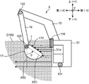
- FIG. 1 is an external view of a construction machine 1 to which an attachment recognition device according to an embodiment of the present invention is applied.
- a hybrid excavator is taken as an example of the construction machine 1, but the attachment recognition device may be applied to other construction machines such as a hydraulic excavator and a crane.
- the front side direction of the cab 31 is described as front
- the rear side direction of the cab 31 is described as rear
- the upper side of the cab 31 is described as upper
- the lower direction of the cab 31 Is described as downward.
- the front and rear are collectively referred to as the front-rear direction
- the upper and lower directions are collectively referred to as the vertical direction.
- the left direction is described as left
- the right direction is described as right.
- the left side and the right side are collectively referred to as the left-right direction.
- the construction machine 1 is attached to a crawler-type lower traveling body 2, an upper revolving body 3 (an example of a main body) provided on the lower traveling body 2 so as to be able to swivel, and the posture can be changed.
- the working device 4 is provided.
- the working device 4 is swingable with respect to the upper swing body 3 with respect to the boom 15 (an example of a movable portion) attached to be able to rise and fall adjacent to the right side of the cab 31 and the tip of the boom 15.
- the arm 16 (an example of a movable part) attached to the arm 16 and the attachment 17 attached so as to be swingable with respect to the attachment attachment part r provided at the tip of the arm 16 are provided.
- the attachment 17 is replaceably mounted at the attachment mounting portion r.
- a bucket, nibra, breaker, or the like can be employed.
- the upper swing body 3 is configured by a box and includes a cab 31 in which an operator boardes.
- the front surface is described as a front surface 31 a.
- a distance sensor 110 is provided at a predetermined position (here, the upper end) of the front surface 31a.
- the distance sensor 110 has a measurement range D100 set so as to cover at least the entire area of the front surface 31a.
- the angle of view of the measurement range D100 is set to approximately 90 degrees, but this is an example.
- the construction machine 1 can issue a warning to the operator, or perform interference prevention control for controlling the work device 4 so that interference with the front surface 31a of the object to be interfered is prevented.
- the construction machine 1 further includes angle sensors 101, 102, and 103.
- the angle sensor 101 is provided at the rotation fulcrum of the boom 15 and measures the rotation angle of the boom 15.
- the angle sensor 102 is provided at the rotation fulcrum of the arm 16 and measures the rotation angle of the arm 16.
- the angle sensor 103 is provided at the rotation fulcrum of the attachment 17 and measures the rotation angle of the attachment 17.
- the upper turning body 3 is provided with a controller 120 that is electrically connected to the distance sensor 110 and controls the entire construction machine 1.
- a memory 130M is electrically connected to the controller 120.
- the memory 130M is configured by a non-volatile storage device, and stores the database 130 illustrated in FIG.
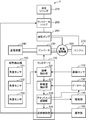
- FIG. 2 is a block diagram showing an example of the system configuration of the construction machine 1 shown in FIG.
- the construction machine 1 is generated by the engine 210, the hydraulic pump 250 and the generator motor 220 connected to the output shaft of the engine 210, the control valve 260 provided between the hydraulic pump 250 and the hydraulic cylinder 270, and the generator motor 220.
- Power storage device 240 that can be charged with electric power
- inverter 230 that converts power between power storage device 240 and generator motor 220.
- the hydraulic pump 250 is operated by the power of the engine 210 and discharges hydraulic oil.
- the hydraulic oil discharged from the hydraulic pump 250 is guided to the hydraulic cylinder 270 in a state where the flow rate is controlled by the control valve 260.
- the hydraulic oil discharged from the hydraulic cylinder 270 is returned to a tank (not shown) by the control valve 260.
- the control valve 260 sets the opening of the valve to an opening corresponding to the operation amount of the operation unit 150 under the control of the controller 120.
- the hydraulic cylinder 270 expands and contracts by receiving the supply of hydraulic oil, and a boom cylinder that raises and lowers the boom 15 with respect to the upper swing body 3, and expands and contracts by receiving the supply of hydraulic oil and
- An arm cylinder that swings the arm 16 and a bucket cylinder that swings the attachment 17 with respect to the arm 16 by expanding and contracting upon receiving the supply of hydraulic oil are included.
- the generator motor 220 has a function as a generator that converts the power of the engine 210 into electric power and a function as an electric motor that converts electric power stored in the power storage device 240 into power.
- the generator motor 220 is configured by, for example, a three-phase motor, but this is an example and may be configured by a single-phase motor.
- the power storage device 240 is composed of various secondary batteries such as a lithium ion battery, a nickel metal hydride battery, an electric double layer capacitor, and a lead battery.
- the inverter 230 controls switching between the operation of the generator motor 220 as a generator and the operation of the generator motor 220 as an electric motor under the control of the controller 120.
- the inverter 230 controls the current to the generator motor 220 and the torque of the generator motor 220 under the control of the controller 120.
- the inverter 230 is configured by, for example, a three-phase inverter. However, this is an example, and the inverter 230 may be configured by a single-phase inverter.
- the construction machine 1 includes an attitude detection unit 100, a distance sensor 110 and a controller 120 shown in FIG. 1, a database 130, a notification unit 140 that notifies the operator of various information, and an operation unit that receives an operator's operation. 150.
- the posture detection unit 100 includes the angle sensors 101, 102, 103 described with reference to FIG. 1 and detects the posture of the work device 4.
- the posture of the work device 4 is specified by the rotation angle of the boom 15, the rotation angle of the arm 16, and the rotation angle of the attachment 17.
- the distance sensor 110 measures the distance distribution of objects around the cab 31 including the attachment 17.
- the distance sensor 110 is configured by, for example, a depth sensor that irradiates infrared rays at regular time intervals (for example, 30 fps), and measures the time from irradiation of infrared rays to reception of reflected light in units of pixels.
- Distance image data indicating the distance distribution of the surrounding environment of the cab 31 is acquired.
- depth sensors that irradiate infrared rays have been increasingly put into practical use as distance measurement means, and are used as an input interface for performing gesture input in games and the like.
- a depth sensor using infrared rays is useful for the construction machine 1.
- the method of measuring the time from when the infrared rays are irradiated until the reflected light is received is known as the ToF (Time of flight) method.
- a pattern irradiation method for measuring a distance from a light receiving pattern of reflected light when a specific pattern is irradiated is known, and a depth sensor of this pattern irradiation method may be adopted. Since the construction machine 1 often works outdoors, a laser scanning ToF type depth sensor that is resistant to interference with sunlight may be employed.
- the depth sensor is used as the distance sensor 110, the present invention is not limited to this, and the distance sensor 110 may be configured by a stereo camera that is relatively inexpensive compared to the depth sensor.
- the controller 120 includes a processor such as a microcontroller and a storage device that stores programs and the like.
- the controller 120 includes a region extraction unit 121, a feature amount extraction unit 122, an attachment recognition unit 123, and a posture control unit 124.
- the region extraction unit 121 to the posture control unit 124 may be configured by a dedicated hardware circuit, or may be realized by a CPU executing a program.
- the region extracting unit 121 extracts a region indicating the distance distribution of the attachment 17 from the distance image data using the posture detected by the posture detecting unit 100.
- FIG. 4 is a diagram showing the working device 4 in a simplified manner.
- the boom 15 and the arm 16 are shown as straight lines for the sake of simplicity.
- the position and posture of the work device 4 are shown in the three-dimensional coordinate system of the construction machine 1.
- the three-dimensional coordinate system of the construction machine 1 is defined by a Y axis indicating the vertical direction, an X axis indicating the front-rear direction, and a Z axis indicating the left-right direction.
- the origin of the Y axis is set, for example, at the base end of the boom 15, the origin of the X axis is set, for example, at the front surface 31a, and the origin of the Z axis is set, for example, at the center in the left-right direction of the front surface 31a. Yes.
- the lengths L1 and L2 of the boom 15 and the arm 16 are known. Therefore, if the rotation angle ⁇ 1 of the boom 15 and the rotation angle ⁇ 2 of the arm 16 with respect to the boom 15 are known, the values of the X coordinate and the Y coordinate of the attachment mounting portion r provided at the tip of the arm 16 can be specified. Also, if the posture of the work device 4 changes in a plane parallel to the YX plane, the position of the base end of the boom 15 in the left-right direction is known, so the value of the Z coordinate of the attachment mounting portion r is also specified. it can.
- the coordinates of the distance image data measured by the distance sensor 110 can be determined from the angle of view of the distance sensor 110, the attachment position, and the angle of the optical axis. It can be determined whether it corresponds to the attachment mounting part r.
- the attachment 17 is represented by a group of pixel data in which depths are continuously distributed. Therefore, if the coordinates of the attachment mounting part r in the distance image data are known, a group of pixel data is extracted using the coordinates as a base point, so that a region indicating a distance distribution indicating the attachment 17 can be extracted from the distance image data.
- the region extraction unit 121 obtains the position of the attachment mounting unit r in the three-dimensional coordinate system of the construction machine 1 from the rotation angles ⁇ 1 and ⁇ 2, and performs coordinate conversion of the obtained position into the three-dimensional coordinate system of the distance sensor 110. Thus, the coordinates of the attachment mounting portion r in the distance image data are obtained. Then, the region extracting unit 121 extracts the region of the attachment 17 by extracting a group of pixel data in which the depth is continuously distributed with the attachment mounting unit r as a base point.
- the feature amount extraction unit 122 extracts the feature amount of the attachment 17 from the region indicating the distance distribution of the attachment 17 extracted by the region extraction unit 121.
- 5 and 6 are explanatory diagrams of the feature amount extraction processing.
- 5 shows a state in which the posture surface A51 that defines the posture of the attachment 17 is positioned parallel to the vertical surface A52
- FIG. 6 shows a state in which the posture surface A51 is positioned at an angle ⁇ with respect to the vertical surface A52.
- Show. 5 and 6 the vertical direction is described as the Y direction, the front and rear direction is described as the X direction, and the horizontal direction is described as the Z direction.
- the posture plane A51 is a plane that passes through the longitudinal direction of the attachment 17, and is a plane that is orthogonal to the XY plane. Note that the angle ⁇ of the posture plane A51 shown in FIG. 6 with respect to the vertical plane A52 can be calculated from the rotation angles ⁇ 1 to ⁇ 3.
- the vertical plane A52 is a plane that passes through the attachment mounting portion r and is orthogonal to the X direction.
- the attachment mounting part r has a depth of Xb and a Y-direction value (altitude) of Yb.
- the feature amount of the attachment 17 is defined by the shape of the surface 171 of the attachment 17 on the cab 31 side.
- the shape of the surface 171 is defined by the height of the surface 171 when the posture surface A51 is used as a reference.
- one column of pixel data groups parallel to the Y direction on the surface 171 has a depth of (X1, X2,..., Xn).
- the posture plane A51 coincides with the vertical plane A52
- the height from the posture plane A51 of the pixel data group in one column is (X1-Xb, X2-Xb,..., Xn ⁇ Xb).
- the height of the posture plane A51 of the pixel data group in another column parallel to the Y direction is also expressed by (X1-Xb, X2-Xb,..., Xn-Xb).
- one column of pixel data group parallel to the Y direction on the surface 171 has a depth of (X1 ′, X2 ′,..., Xn ′).
- the posture plane A51 is positioned at an angle ⁇ counterclockwise with respect to the vertical plane A52, (X1′ ⁇ Xb, X2′ ⁇ Xb,..., Xn′ ⁇ Xb) Does not represent the height from the posture plane A51.
- the pixel data group having the depth of (X1 ′, X2 ′,..., Xn ′) is rotated clockwise by the angle ⁇ around the attachment mounting part r to obtain (X1′_ ⁇ , X2′_ ⁇ ). ,..., Xn′_ ⁇ ).
- (X1′_ ⁇ Xb, X2′_ ⁇ -Xb,..., Xn′_ ⁇ Xb) is the surface 171 when the posture surface A51 is used as a reference. Will be shown.
- the feature quantity extraction unit 122 first calculates the angle ⁇ using the rotation angles ⁇ 1 to ⁇ 3. Next, the pixel data group of all columns parallel to the Y direction and indicating the surface 171 of the attachment 17 extracted by the region extraction unit 121 is subjected to a rotation matrix calculation centered on the attachment mounting unit r on the XY plane. , Rotate the angle ( ⁇ ). Then, the feature amount extraction unit 122 applies (X1_ ⁇ -Xb, X2_ ⁇ -Xb,..., Xn_ ⁇ ) to the pixel data group (X1_ ⁇ , X2_ ⁇ ,..., Xn_ ⁇ ) rotated by the angle ( ⁇ ).
- the feature amounts (X1 ′′, X2 ′′,..., Xn ′′) indicate the height of the attachment 17 from the posture surface A51.
- the database 130 stores the height of the surface 171 of the reference attachment with respect to the posture surface A51 as a feature amount of the reference attachment. Therefore, the feature values (X1 ′′, X2 ′′,..., Xn ′′) of the attachment 17 can be collated with the feature values of the reference attachment stored in the database 130.
- the feature amount extraction unit 122 rotates the pixel data group of all columns parallel to the Y direction, but the feature amount of the reference attachment is composed of data for one column parallel to the Y direction. For example, only one column of pixel data groups parallel to the Y direction may be rotated.
- the attachment recognition unit 123 collates the feature amount extracted by the feature amount extraction unit 122 with the feature amount of one or more reference attachments stored in the database 130 to recognize the attachment 17. Specifically, the attachment recognition unit 123 resembles the feature amount (X1 ′′, X2 ′′,..., Xn ′′) of the attachment 17 and the feature amount of each reference attachment stored in the database 130. A reference attachment having a similarity that is equal to or higher than the standard similarity and having the maximum similarity is recognized as an attachment of the same type as the attachment 17.
- the feature amount is represented by three-dimensional data indicating the height distribution of the surface 171 when the posture plane A51 is used as a reference.
- the attachment recognizing unit 123 may calculate the similarity using a Jackard coefficient or a dice coefficient that can calculate the similarity between the three-dimensional point groups.
- the posture control unit 124 controls the posture of the work device 4 so as to take a posture corresponding to the operation amount output from the operation unit 150. Further, the posture control unit 124 detects the distance of the interference target from the cab 31 using the posture of the working device 4 detected by the posture detection unit 100 and the distance image data measured by the distance sensor 110, for example. When the distance is equal to or less than the reference distance, interference prevention control is performed to control the work device 4 so that the interference target does not interfere with the cab 31. In addition, when the distance from the cab 31 to the interference target is equal to or less than the reference distance, the posture control unit 124 notifies the operator of the risk of interference using the notification unit 140.
- the database 130 stores in advance feature quantities of one or more reference attachments.
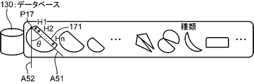
- FIG. 3 is a diagram conceptually showing the feature quantity of the reference attachment stored in the database 130.
- the database 130 stores feature amounts of various attachments such as buckets, breakers, and nibbles.
- the height (H1, H2,..., Hn) of the surface 171 with respect to the posture surface A51 is adopted as the feature amount of the reference attachment.
- the feature amount extraction unit 122 calculates the feature amount of the attachment 17 by rotating the pixel data group (X1, X2,..., Xn) by an angle ( ⁇ ).
- the present invention is not limited to this.
- the feature amount extraction unit 122 may extract the pixel data group (X1-Xb, X2-Xb,..., Xn-Xb) as the feature amount of the attachment 17.
- the attachment recognizing unit 123 may rotate the reference attachment by the angle ⁇ and match the feature quantity of the reference attachment after the rotation with the feature quantity of the attachment 17.
- the attachment recognizing unit 123 rotates the reference attachment by an angle ⁇ with respect to the vertical plane A ⁇ b> 52 with the base point P ⁇ b> 17 as the rotation center, so that the reference attachment has the same posture as the attachment 17. To do. And the attachment recognition part 123 should just obtain
- FIG. The base point P17 indicates the mounting position on the attachment mounting part r.
- the notification unit 140 includes a buzzer, a display panel, and a warning lamp provided in the cab 31 and warns the operator under the control of the attitude control unit 124.
- the operation unit 150 includes an operation lever that receives an operation by an operator for changing the posture of the work device 4, and a mode setting button that receives an input of a mode setting command by the operator for setting the operation mode of the construction machine 1. .
- the mode setting button may be configured with a touch panel display.
- the operation lever outputs a signal indicating the operation amount to the controller 120.
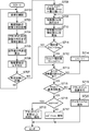
- FIG. 7 is a flowchart showing processing of the attachment recognition apparatus in Embodiment 1 of the present invention. This flowchart is executed, for example, when the engine 210 of the construction machine 1 is started.
- the posture detection unit 100 detects the posture of the work device 4.
- the region extraction unit 121 determines whether or not the posture of the work device 4 is within the distance measurement possible range from the detected posture (S702).
- the region extracting unit 121 may determine that the posture of the work device 4 is within the distance measurement possible range when at least the entire attachment 17 has entered the measurement range D100.
- the region extraction unit 121 obtains the position of the attachment mounting portion r of the arm 16 using the method described in FIG.
- the area extraction unit 121 measures the distance image data that does not include the attachment 17 by monitoring the posture of the work device 4 until the posture of the work device 4 falls within the distance measurement possible range. Is preventing.
- the distance sensor 110 acquires distance image data indicating the distance distribution of surrounding objects in the cab 31 (S703). On the other hand, if the posture of the work device 4 is not within the distance measurement possible range (NO in S702), the process returns to S701.
- the region extraction unit 121 obtains the coordinates of the attachment mounting unit r in the distance image data using the postures (rotation angles ⁇ 1 to ⁇ 3) detected in S701, and a group of pixels having continuous depths from the coordinates. Data is extracted as an area indicating the distance distribution of the attachment 17.
- the feature amount extraction unit 122 calculates the angle ⁇ of the posture plane A51 using the posture (rotation angles ⁇ 1 to ⁇ 3) detected in S701 (S705).
- the feature amount extraction unit 122 rotates the pixel data group constituting the region extracted in S704 by an angle ( ⁇ ) in the XY plan view, and (X1_ ⁇ Xb, X2_ ⁇ Xb,. .., Xn_ ⁇ Xb), the feature amount of the attachment 17 is extracted (S706).
- the feature quantity extraction unit 122 averages the extracted feature quantities. For example, in the loop from S701 to S707, the feature amount extraction unit 122 adds the feature amount calculated in the current loop to the average value of the feature amount calculated in the previous loop and averages the feature amount. Find the amount. Thereby, the feature-value in which the influence of noise and measurement variation was suppressed is obtained.
- the attachment recognizing unit 123 sets a variable n for specifying one notable reference attachment to an initial value (for example, “0”), and sets a variable ind for specifying the reference attachment having the maximum similarity.
- the initial value is set, and the maximum similarity Smax is set to a minimum value (for example, “ ⁇ 1”) (S708).
- the attachment recognizing unit 123 reads out the feature quantity C (n) of the reference attachment from the database 130 (S709).
- the attachment recognizing unit 123 calculates the similarity S (n) between the feature C (n) and the averaged feature calculated in S706, that is, the feature 17 of the attachment 17 (S710). .
- the attachment recognition unit 123 sets the maximum similarity Smax to the similarity S (n) and sets the variable ind to n. Setting is performed (S712).
- the similarity S (n) is not greater than the maximum similarity Smax (NO in S711), the process proceeds to S713.
- the similarity S (n) of the reference attachment most similar to the attachment 17 among the reference attachments read up to the present time is stored in the maximum similarity Smax.
- the variable ind stores a variable n for specifying the reference attachment most similar to the attachment 17 among the reference attachments read up to the present time.
- the attachment recognition unit 123 increments the variable n by 1 (S714), and performs the processing. Return to S709. Thereby, the feature quantity C (n + 1) of the next reference attachment is read from the database 130, and the similarity S (n + 1) between the feature quantity C (n + 1) and the feature quantity of the attachment 17 is calculated. On the other hand, if the feature amount C (n) of all the reference attachments has been read from the database 130 (YES in S713), the process proceeds to S715. That is, by repeating the processing of S709 to S713, a reference attachment that is a candidate for the attachment 17 among all the reference attachments is determined.
- the attachment recognition unit 123 determines whether or not the maximum similarity Smax is greater than the reference similarity. If the maximum similarity Smax is larger than the standard similarity (YES in S715), the attachment recognition unit 123 determines that the candidate reference attachment corresponds to the attachment 17, and the variable ind is currently stored in the memory 130M. It is determined whether or not it is equal to the existing variable ind ′ (S716).
- the attachment recognizing unit 123 determines that the attachment 17 has not been changed, and notifies the notification unit 140 of that fact (S718). In this case, the alerting
- the attachment recognition unit 123 determines that the attachment 17 has been changed, updates the variable ind ′ with the variable ind, and indicates that the attachment 17 has been changed. Is notified to the notification unit 140 (S717).
- the notification unit 140 may output a message such as “Attachment has been changed” using sound or an image. Thereafter, as indicated by the updated variable ind ', the reference attachment is recognized as the attachment 17 attached to the work device 4, and interference prevention control or the like is performed.
- the attachment recognition unit 123 determines that the attachment 17 cannot be recognized (S719). Accordingly, it is possible to prevent the attachment 17 from being determined as one of the reference attachments even though the same kind of attachment as the attachment 17 is not stored in the database 130.
- the attachment recognition unit 123 adds the feature amount of the attachment 17 to the database 130 (S720). Thereby, a new attachment is registered in the database. Thereby, the situation where a new attachment is not recognized can be prevented.
- recognition of various attachments other than buckets can be performed in a short time without inputting identification information for attachments manually. It can be carried out.
- the second embodiment is characterized in that the operation mode of the construction machine 1 is set to the recognition mode for recognizing the attachment 17.
- the same components as those in the first embodiment are denoted by the same reference numerals and description thereof is omitted.
- FIG. 8 is a block diagram showing a system configuration of the attachment recognition apparatus according to Embodiment 2 of the present invention. 8 is different from FIG. 2 in that a mode setting unit 125 is added.
- the mode setting unit 125 sets the operation mode of the construction machine 1 to the recognition mode for recognizing the attachment 17.
- the mode setting unit 125 may set the operation mode of the construction machine 1 to the recognition mode when a mode setting button provided in the operation unit 150 is pressed by the operator.
- the posture control unit 124 controls the control valve so that the posture of the working device 4 becomes a predetermined measurement posture (an example of a specific posture). 260 is controlled.
- a posture for measurement a posture in which the posture surface A51 of the attachment 17 is parallel to the vertical surface A52 can be employed. This is because the feature amount of the reference attachment is defined by the height of the surface 171 of the reference attachment with reference to the posture surface A51 as shown in FIG.
- the posture surface A51 has a constant angle ⁇ with respect to the vertical surface A52
- the posture for measurement it is assumed that the height of the surface 171 of the reference attachment from the vertical plane A52 when the database 130 positions the posture plane A51 at the angle ⁇ with respect to the vertical plane A52 is stored as the feature amount of the reference attachment.
- the measurement posture may be a posture in which the posture surface A51 is inclined by the angle ⁇ with respect to the vertical surface A52.
- FIG. 9 is a flowchart showing the processing of the attachment recognition apparatus in the second embodiment of the present invention. In FIG. 9, the same processes as those in FIG.
- This flowchart starts when the recognition mode is set.
- the posture control unit 124 controls the control valve 260 so that the posture of the work device 4 becomes the posture for measurement (S1101).
- the posture of the work device 4 is controlled to predetermined rotation angles ⁇ 1 to ⁇ 3 so that the posture surface A51 takes a posture that coincides with the vertical surface A52.
- the working device 4 is automatically controlled to take the measurement posture.
- the posture control unit 124 switches the posture of the work device 4 to the measurement posture at a low speed so that there is no problem even if the work device 4 comes into contact with a human body or surrounding objects. That's fine.
- the posture control unit 124 may perform reaction force control that moves the work device 4 in a direction away from the human body or the peripheral object.
- the posture control unit 124 may cause the operator to operate the operation unit 150 to change the posture of the work device 4 to a measurement posture.
- the posture control unit 124 notifies the guidance for setting the posture of the work device 4 to the measurement posture using the notification unit 140, and when the posture of the work device 4 becomes the measurement posture, this is indicated. What is necessary is just to alert
- the information on the attachment 17 changes, so the feature quantity of the attachment 17 cannot be accurately extracted.
- the recognition accuracy of the attachment 17 may be reduced.
- the posture of the work device 4 is changed to the posture for measurement, and the process for recognizing the attachment 17 is executed. Therefore, it is possible to extract the feature amount of the attachment 17 itself, and it is possible to prevent the recognition accuracy of the attachment 17 from being lowered.
- the database 130 is provided in the memory 130M of the construction machine 1, but the present invention is not limited to this, and the database 130 may be provided in a cloud server.
- the construction machine 1 may include a communication device for communicating with the cloud server.
- the attachment 17 may be recognized using the database 130 of the cloud server.
- you may request the process which recognizes the attachment 17 to a cloud server.
- the attachment recognition unit 123 and the database 130 may be provided in the cloud server.
- the construction machine 1 may perform processing until the feature amount of the attachment 17 is extracted, transmit the extraction result to the cloud server, and make a recognition processing request for the attachment 17 to the cloud server. Thereby, more various attachments 17 can be recognized.
- the attachment 17 modified on the user side may be attached to the work device 4.
- the feature quantity of such an attachment 17 cannot be stored in the database 130 in advance, such an attachment 17 may not be recognized permanently.
- interference prevention control and operation control suitable for the attachment 17 are not performed. Therefore, in the present embodiment, the process of S720 shown in FIGS. 7 and 9 is provided, and the feature quantity of the attachment 17 that could not be recognized is added to the database 130.
- Modification 2 In S720, the feature amount of the attachment 17 is described as being added to the database 130.
- the attachment recognition unit 123 may calculate the size and weight of the attachment from the feature amount of the attachment 17 and store the obtained size and weight in the database 130 together with the feature amount.
- the size, width, and depth of the cuboid when the cuboid circumscribing the attachment 17 is applied can be adopted.
- L3 is the length and L4 is the depth.
- the width is the length of the attachment 17 in the left-right direction (Z direction).
- the weight can be calculated by multiplying the volume of the attachment 17 by the density of the assumed attachment 17. Thereby, the interference prevention control and operation control suitable for the attachment 17 can be performed.
- Modification 3 Although the database 130 has been described as storing only the feature amount of the reference attachment, the present invention is not limited to this, and the size and weight of the reference attachment may be stored together with the feature amount. In this case, the attachment recognition apparatus can obtain the attachment 17 size and weight from the database 130 without calculating the size and weight of the attachment 17 from the feature amount of the attachment 17. Accordingly, appropriate interference prevention control and operation control can be performed according to the size and weight of the attachment 17.
- the attachment recognition unit 123 may calculate the size and weight of the attachment 17 from the feature amount of the attachment 17, and may calculate the similarity with the reference attachment by including the calculated size and weight in the feature amount. Thereby, the attachment 17 can be recognized more accurately.
- An attachment recognition apparatus includes: In a construction machine including a work device including an attachment mounting unit on which a plurality of types of attachments are replaceably mounted, an attachment recognition device that recognizes an attachment mounted on the attachment mounting unit, An attitude detection unit for detecting the attitude of the working device; A distance sensor for measuring a distance distribution of a surrounding object including the attached attachment; A region extracting unit that extracts a region indicating the distance distribution of the attached attachment from the distance distribution measured by the distance sensor using the posture detected by the posture detecting unit; A feature amount extraction unit that extracts a feature amount of the attached attachment from the region extracted by the region extraction unit; A database that pre-stores feature quantities of one or more types of reference attachments; An attachment recognition unit that compares the feature amount extracted by the feature amount extraction unit with the feature amount of the reference attachment and recognizes the attached attachment;
- the region indicating the distance distribution of the attachment is extracted from the distance distribution of the surrounding object including the attachment measured by the distance sensor, using the posture of the attachment. Then, the feature amount of the attachment is extracted from the extracted region, the feature amount of the extracted attachment is collated with the feature amount of the reference attachment stored in advance in the database, and the attached attachment is recognized.
- this aspect can recognize the attachment even if the identification information of the attachment is not input manually. Further, since the attachment can be recognized without measuring the attachment before replacement, the measurement work can be completed in a short time. In addition, measurement work can be performed at an arbitrary timing after replacement. In addition, by storing feature values of various reference attachments in the database, various attachments can be recognized.
- a mode setting unit that sets an operation mode of the construction machine in a recognition mode for recognizing the attached attachment based on an input of a mode setting command;
- a posture control unit that, when the recognition mode is set by the mode setting unit, causes the attached attachment to have a predetermined specific posture;
- the distance sensor may measure a distance distribution when the posture of the attached attachment is changed to the specific posture by the posture control unit.
- the distance distribution when the posture of the attachment is changed to the specific posture is measured by the posture control unit, and the attachment is recognized based on the measured distance distribution. For this reason, it is possible to prevent attachment recognition errors due to attachment information changes that occur during operation of the construction machine (for example, sand in the bucket, grabbing objects with a nibler, etc.).
- the database may store the distance distribution of the reference attachment as the feature amount when the posture of the reference attachment is set to the specific posture.
- the distance distribution of the reference attachment when it is in a specific posture is stored in the database in advance as the feature quantity of the reference attachment, the feature quantity of the attachment to be recognized is used as it is in the database. It can be collated with the feature quantity of the stored reference attachment.
- the construction machine includes a main body portion
- the working device includes a movable part that is swingably connected to the main body part and has the attachment mounting part provided at a tip thereof.
- the attachment is swingably connected to the attachment mounting portion
- the feature amount of the reference attachment is defined by the height of the surface of the reference attachment relative to the posture surface that defines the posture of the reference attachment
- the feature amount extraction unit rotates the distance distribution extracted by the region extraction unit around the attachment mounting unit so that a posture surface that defines the posture of the attachment faces a vertical direction, and the rotation is performed. A difference between the distance distribution and the distance of the attachment mounting portion may be calculated as the feature amount.
- the feature amount of the reference attachment is defined by the height of the surface of the reference attachment with respect to the posture surface that defines the posture of the reference attachment. Therefore, it is necessary to adopt the height of the surface of the attachment with respect to the posture surface as the feature amount of the attachment.
- the distance distribution of the attachment is rotated around the attachment mounting portion so that the posture surface of the attachment is oriented in the vertical direction
- the distance distribution of the attachment after rotation and the distance of the attachment mounting portion The difference represents the height of the surface of the attachment with respect to the posture surface. Therefore, in this aspect, the feature amount of the attachment suitable for comparison with the feature amount of the reference attachment can be calculated by a simple process.
- the attachment recognition unit when the attachment recognition unit fails to recognize the attached attachment as a result of the collation, the attachment recognition unit may add the feature quantity of the attachment that could not be recognized to the database.
- the feature quantity of the attachment to be recognized is not stored in the database, the feature quantity of the attachment is added to the database, so that the attachment can be prevented from remaining unrecognized. Further, even when an unexpected attachment is mounted on the user side, the database can be constructed so that the attachment is recognized.
- the information processing apparatus may further include a notification unit that notifies a recognition result of the attached attachment by the attachment recognition unit.
Landscapes
- Engineering & Computer Science (AREA)
- Mining & Mineral Resources (AREA)
- Civil Engineering (AREA)
- General Engineering & Computer Science (AREA)
- Structural Engineering (AREA)
- Mechanical Engineering (AREA)
- Computer Vision & Pattern Recognition (AREA)
- Physics & Mathematics (AREA)
- General Physics & Mathematics (AREA)
- Theoretical Computer Science (AREA)
- Quality & Reliability (AREA)
- Component Parts Of Construction Machinery (AREA)
- Image Analysis (AREA)
- Image Processing (AREA)
- Operation Control Of Excavators (AREA)
Abstract
領域抽出部(121)は、姿勢検出部(100)により検出された姿勢を用いて、距離センサ(110)が取得した距離画像データから、アタッチメント(17)の距離分布を示す領域を抽出する。特徴量抽出部(122)は、領域抽出部(121)により抽出されたアタッチメント(17)の距離分布を示す領域からアタッチメント(17)の特徴量を抽出する。アタッチメント認識部(123)は、特徴量抽出部(122)により抽出された特徴量と、データベース(130)に記憶された1以上の参照アタッチメントの特徴量とを照合し、アタッチメント(17)を認識する。
Description
本発明は、複数種類のアタッチメントが交換可能に装着されるアタッチメント装着部を含む作業装置を備える建設機械において、前記アタッチメント装着部に装着されたアタッチメントを認識するアタッチメント認識装置に関するものである。
油圧ショベル等の交換可能なアタッチメントを備える建設機械においては、ユーザは、バケット、ニブラ、又はブレーカー等のアタッチメントを、作業内容に応じて適宜変更して作業を行う。アタッチメントの寸法などの情報を建設機械が認識していない場合、アタッチメントの運転室への干渉を防止する干渉防止制御や、アタッチメントに応じた作業装置の動作制御(例えばバケットの自動水平引き制御など)を有効に機能せることができないおそれがある。そのため、建設機械は、現在取り付けられているアタッチメントを認識しておく必要がある。
アタッチメントの認識方法やアタッチメントの寸法の計測方法としては以下の特許文献1、2が公知である。
特許文献1は、サービスマンによりアタッチメントの交換作業が行われた場合、サービスマンにアタッチメントの識別情報を入力させ、その識別情報を入力日時と併せて端末装置に対して送信させ、端末装置が建設機械が装着するアタッチメントを管理する技術を開示する。
特許文献2は、交換前のアタッチメントである基準アタッチメント及び交換用アタッチメントを所定の測定用姿勢にしたときの基準アタッチメント及び交換用アタッチメント同士の所定部位の測定データの差を求め、求めた差と予め記憶された基準アタッチメントの寸法形状に関する数値データとに基づいて、交換用アタッチメントの寸法形状に関する数値データを演算する技術を開示する。
具体的には、特許文献2では、バケットの交換前後で、先端を地面に接触させて上面を鉛直方向に一致させる姿勢にバケットの姿勢が設定され、ブーム及びアームの角度が測定され、測定された角度を所定の演算式に代入し、アタッチメント長さが求められている。
しかし、特許文献1は、サービスマンによる識別情報の手入力を前提とするので、入力ミスや入力忘れなどのヒューマンエラーが発生するという問題がある。
特許文献2は、オペレータの操作により、基準アタッチメント及び交換用アタッチメントの両アタッチメントが測定用姿勢に設定されているので、計測に時間がかかるという問題がある。また、特許文献2は、交換前のアタッチメントである基準アタッチメントを計測する必要があるので、アタッチメントの交換時に計測作業を怠った場合、交換用アタッチメントを認識できなくなるという問題がある。
本発明は、アタッチメントの認識においてアタッチメントの識別情報を入力しなくても、短時間でアタッチメントの認識を行うことができるアタッチメント認識装置を提供することを目的とする。
本発明の一態様に係るアタッチメント認識装置は、
複数種類のアタッチメントが交換可能に装着されるアタッチメント装着部を含む作業装置を備える建設機械において、前記アタッチメント装着部に装着されたアタッチメントを認識するアタッチメント認識装置であって、
前記作業装置の姿勢を検出する姿勢検出部と、
前記装着されたアタッチメントを含む周囲物体の距離分布を計測する距離センサと、
前記姿勢検出部により検出された姿勢を用いて、前記距離センサにより計測された距離分布から、前記装着されたアタッチメントの距離分布を示す領域を抽出する領域抽出部と、
前記領域抽出部により抽出された領域から前記装着されたアタッチメントの特徴量を抽出する特徴量抽出部と、
1種類以上の参照アタッチメントの特徴量を予め記憶するデータベースと、
前記特徴量抽出部により抽出された特徴量と、前記参照アタッチメントの特徴量とを照合し、前記装着されたアタッチメントを認識するアタッチメント認識部とを備える。
この構成によれば、人手によりアタッチメントの識別情報を入力しなくても、アタッチメントを認識できる。また、交換前のアタッチメントを計測する必要がないので、計測作業を短時間で終了させることができる。
(実施の形態1)
図1は、本発明の実施の形態におけるアタッチメント認識装置が適用された建設機械1の外観図である。ここでは、建設機械1としてハイブリッドショベルを例に挙げるが、これ以外の油圧ショベル、クレーン等の建設機械にアタッチメント認識装置は適用されてもよい。以下、運転室31の前側の方向を前方と記述し、運転室31の後側の方向を後方と記述し、運転室31の上側の方向を上方と記述し、運転室31の下側の方向を下方と記述する。また、前方と後方とを総称して前後方向と記述し、上方と下方とを総称して上下方向と記述する。また、運転室31から前方を見て左側の方向を左方と記述し、右方向を右方と記述する。また、左方と右方とを総称して左右方向と記述する。
図1は、本発明の実施の形態におけるアタッチメント認識装置が適用された建設機械1の外観図である。ここでは、建設機械1としてハイブリッドショベルを例に挙げるが、これ以外の油圧ショベル、クレーン等の建設機械にアタッチメント認識装置は適用されてもよい。以下、運転室31の前側の方向を前方と記述し、運転室31の後側の方向を後方と記述し、運転室31の上側の方向を上方と記述し、運転室31の下側の方向を下方と記述する。また、前方と後方とを総称して前後方向と記述し、上方と下方とを総称して上下方向と記述する。また、運転室31から前方を見て左側の方向を左方と記述し、右方向を右方と記述する。また、左方と右方とを総称して左右方向と記述する。
建設機械1は、クローラ式の下部走行体2と、下部走行体2上に旋回可能に設けられた上部旋回体3(本体部の一例)と、上部旋回体3に取り付けられ、姿勢が変更可能な作業装置4とを備えている。
作業装置4は、上部旋回体3に対し、運転室31の例えば右方に隣接して起伏可能に取り付けられたブーム15(可動部の一例)と、ブーム15の先端部に対して揺動可能に取り付けられたアーム16(可動部の一例)と、アーム16の先端に設けられたアタッチメント装着部rに対して揺動可能に装着されたアタッチメント17とを備えている。アタッチメント17はアタッチメント装着部rにおいて交換可能に装着されている。アタッチメント17としては、バケット、ニブラ、ブレーカーなどが採用できる。
上部旋回体3は、箱体で構成され、オペレータが搭乗する運転室31を備える。運転室31において、前方側の面を前面31aと記述する。
前面31aの所定の位置(ここでは、上端)には距離センサ110が設けられている。距離センサ110は、少なくとも前面31aの全域をカバーできるように計測範囲D100が設定されている。図1の例では、計測範囲D100の画角はほぼ90度に設定されているが、これは一例である。
これにより、前面31aにおいて距離センサ110の死角が発生せず、アタッチメント17の先端やアタッチメント17が把持する障害物等の干渉対象物が前面31aから所定距離範囲内に侵入したときに、建設機械1は、オペレータに警告を発報したり、干渉対象物の前面31aへの干渉が防止されるように作業装置4を制御する干渉防止制御を行ったりすることが可能となる。
建設機械1は、更に、角度センサ101,102,103を備える。角度センサ101は、ブーム15の回転支点に設けられ、ブーム15の回転角度を計測する。角度センサ102は、アーム16の回転支点に設けられ、アーム16の回転角度を計測する。角度センサ103は、アタッチメント17の回転支点に設けられ、アタッチメント17の回転角度を計測する。
上部旋回体3には、距離センサ110と電気的に接続され、建設機械1の全体を制御するコントローラ120が設けられている。コントローラ120には、メモリ130Mが電気的に接続されている。メモリ130Mは、不揮発性の記憶装置で構成され、図2に示すデータベース130を記憶する。
図2は、図1に示す建設機械1のシステム構成の一例を示すブロック図である。建設機械1は、エンジン210と、エンジン210の出力軸に連結された油圧ポンプ250及び発電電動機220と、油圧ポンプ250及び油圧シリンダ270間に設けられたコントロールバルブ260と、発電電動機220により発電された電力が充電可能な蓄電装置240と、蓄電装置240と発電電動機220との電力の変換を行うインバータ230とを備えている。
油圧ポンプ250は、エンジン210の動力により作動して、作動油を吐出する。油圧ポンプ250から吐出された作動油は、コントロールバルブ260によって流量制御された状態で、油圧シリンダ270に導かれる。なお、油圧シリンダ270から排出された作動油はコントロールバルブ260によって図略のタンクに戻される。
コントロールバルブ260は、コントローラ120の制御の下、操作部150の操作量に応じた開度に弁の開度を設定する。
油圧シリンダ270は、作動油の供給を受けて伸縮することにより、上部旋回体3に対してブーム15を起伏させるブームシリンダと、作動油の供給を受けて伸縮することにより、ブーム15に対してアーム16を揺動させるアームシリンダと、作動油の供給を受けて伸縮することにより、アーム16に対してアタッチメント17揺動させるバケットシリンダとを含む。
発電電動機220は、エンジン210の動力を電力に変換する発電機としての機能と、蓄電装置240が蓄える電力を動力に変換する電動機としての機能とを備えている。図2の例では、発電電動機220は例えば三相モータで構成されているが、これは一例であり、単相モータで構成されていてもよい。
蓄電装置240は、例えば、リチウムイオンバッテリ、ニッケル水素バッテリ、電気二重層キャパシタ、及び鉛バッテリといった種々の二次電池で構成される。
インバータ230は、コントローラ120の制御の下、発電電動機220の発電機としての作動と、発電電動機220の電動機としての作動との切り換えを制御する。また、インバータ230は、コントローラ120の制御の下、発電電動機220に対する電流及び発電電動機220のトルクを制御する。図2の例では、インバータ230は例えば、3相インバータで構成されているが、これは一例であり単相インバータで構成されていてもよい。
更に、建設機械1は、姿勢検出部100と、図1に示した距離センサ110及びコントローラ120と、データベース130と、オペレータに種々の情報を報知する報知部140と、オペレータの操作を受け付ける操作部150とを備えている。
姿勢検出部100は、図1で説明した角度センサ101,102,103を備え、作業装置4の姿勢を検出する。ここでは、ブーム15の回転角度、アーム16の回転角度、及びアタッチメント17の回転角度によって作業装置4の姿勢が特定される。
距離センサ110は、アタッチメント17を含む運転室31の周囲物体の距離分布を計測する。ここで、距離センサ110は、例えば、一定の時間毎(例えば30fps)で赤外線を照射し、赤外線を照射してから反射光を受信するまでの時間を画素単位で計測する深度センサで構成され、運転室31の周辺環境の距離分布を示す距離画像データを取得する。
赤外線を照射する深度センサは、距離計測手段として近年実用化例が増えてきており、ゲームなどでゼスチャ入力を行うための入力インターフェースとして活用されている。また、建設機械1は夜間に使用されることもあるので、赤外線を用いた深度センサは建設機械1にとって有用である。なお、赤外線を照射する深度センサにおいては、上記のように赤外線を照射してから反射光を受信するまでの時間を計測する方式はToF(Time of flight)方式として知られている。その他、深度センサとしては、特定パターンを照射した際の反射光の受光パターンから距離を計測するパターン照射方式が知られており、このパターン照射方式の深度センサが採用されてもよい。建設機械1は屋外で作業することが多いため、太陽光との干渉に強いレーザー走査ToF方式の深度センサが採用されてもよい。
ここでは、距離センサ110として深度センサを用いたが、本発明はこれに限定されず、深度センサに比べて比較的安価なステレオカメラで距離センサ110は構成されてもよい。
コントローラ120は、例えば、マイクロコントローラ等のプロセッサ及びプログラム等を記憶する記憶装置で構成されている。そして、コントローラ120は、領域抽出部121、特徴量抽出部122、アタッチメント認識部123、及び姿勢制御部124を備えている。領域抽出部121~姿勢制御部124は、専用のハードウェア回路で構成されてもよいし、CPUがプログラムを実行することで実現されてもよい。
領域抽出部121は、姿勢検出部100により検出された姿勢を用いて、距離画像データから、アタッチメント17の距離分布を示す領域を抽出する。
図4は、作業装置4を簡略化して示した図である。図4において、ブーム15及びアーム16は説明を簡略化するために直線で示されている。図4に示すように、作業装置4の位置及び姿勢は、建設機械1の3次元座標系で示される。図4の例では、建設機械1の3次元座標系は、上下方向を示すY軸、前後方向を示すX軸、左右方向を示すZ軸によって規定される。Y軸の原点は、例えば、ブーム15の基端に設定され、X軸の原点は、例えば、前面31aに設定され、Z軸の原点は、例えば、前面31aの左右方向の中心に設定されている。
ブーム15及びアーム16の長さL1,L2は既知である。よって、ブーム15の回転角度θ1と、アーム16のブーム15に対する回転角度θ2とが分かれば、アーム16の先端に設けられたアタッチメント装着部rのX座標及びY座標の値を特定できる。また、作業装置4がY-X平面と平行な面内で姿勢が変化するとすれば、ブーム15の基端の左右方向の位置が既知であるため、アタッチメント装着部rのZ座標の値も特定できる。
そして、アタッチメント装着部rのX,Y,Z座標の値が分かれば、距離センサ110の画角、取り付け位置、及び光軸の角度から、距離センサ110で計測される距離画像データのどの座標がアタッチメント装着部rに対応するかを決定できる。
一方、距離画像データ内において、アタッチメント17は深度が連続的に分布する一群の画素データによって表される。そのため、距離画像データ内でのアタッチメント装着部rの座標が分かれば、その座標を基点として一群の画素データを抽出することで、距離画像データからアタッチメント17を示す距離分布を示す領域を抽出できる。
そこで、領域抽出部121は、回転角度θ1,θ2から建設機械1の3次元座標系でのアタッチメント装着部rの位置を求め、求めた位置を距離センサ110の3次元座標系に座標変換することで、距離画像データでのアタッチメント装着部rの座標を求める。そして、領域抽出部121は、アタッチメント装着部rを基点に深度が連続的に分布する一群の画素データを抽出することでアタッチメント17の領域をを抽出する。
特徴量抽出部122は、領域抽出部121により抽出されたアタッチメント17の距離分布を示す領域からアタッチメント17の特徴量を抽出する。
図5及び図6は、特徴量の抽出処理の説明図である。図5は、アタッチメント17の姿勢を規定する姿勢面A51が鉛直面A52と平行に位置決めされた状態を示し、図6は、姿勢面A51が鉛直面A52に対して角度θで位置決めされた状態を示している。図5、図6において上下方向をY方向と記述し、前後方向をX方向と記述し、左右方向をZ方向と記述する。
姿勢面A51は、アタッチメント17の長手方向を通る平面であり、X-Y平面と直交する平面である。なお、図6に示す姿勢面A51の鉛直面A52に対する角度θは回転角度θ1~θ3から算出できる。鉛直面A52は、アタッチメント装着部rを通り、X方向と直交する平面である。アタッチメント装着部rは、深度がXbであり、Y方向の値(高度)がYbである。
アタッチメント17の特徴量は、アタッチメント17の、運転室31側の表面171の形状によって規定される。表面171の形状は、姿勢面A51を基準としたときの、表面171の高さで規定される。図5では、表面171においてY方向と平行なある1列の画素データ群は、(X1,X2,・・・,Xn)の深度を持っている。図5では、姿勢面A51が鉛直面A52と一致しているので、この1列の画素データ群の姿勢面A51からの高さは、(X1-Xb,X2-Xb,・・・,Xn-Xb)で表される。また、表面171において、Y方向と平行な他の列の画素データ群の姿勢面A51の高さも、(X1-Xb,X2-Xb,・・・,Xn-Xb)で表される。
一方、図6では、表面171においてY方向と平行なある1列の画素データ群は、(X1’,X2’,・・・,Xn’)の深度を持っている。しかし、図6では、姿勢面A51が鉛直面A52に対して、反時計回りに角度θで位置決めされているので、(X1’-Xb,X2’-Xb,・・・,Xn’-Xb)は姿勢面A51からの高さを表していない。
この場合、アタッチメント装着部rを中心に、(X1’,X2’,・・・,Xn’)の深度を持つ画素データ群を時計回りに角度θ回転させて、(X1’_θ,X2’_θ,・・・,Xn’_θ)を求める。すると、姿勢面A51が鉛直面A52と一致するので、(X1’_θ-Xb,X2’_θ-Xb,・・・,Xn’_θ-Xb)は、姿勢面A51を基準としたときの表面171の高さを示すことになる。
そこで、特徴量抽出部122は、まず、回転角度θ1~θ3を用いて角度θを算出する。次に、領域抽出部121により抽出されたアタッチメント17の表面171を示す、Y方向と平行な全列の画素データ群を、X-Y平面において、アタッチメント装着部rを中心とする回転行列演算により、角度(-θ)回転させる。そして、特徴量抽出部122は、角度(-θ)回転された画素データ群(X1_θ,X2_θ,・・・,Xn_θ)に対して、(X1_θ-Xb,X2_θ-Xb,・・・,Xn_θ-Xb)の演算を行うことで、アタッチメント17の特徴量(X1’’(=X1_θ-Xb),X2’’(=X2_θ-Xb),・・・,Xn’’(=Xn_θ-Xb))を算出する。
これにより、特徴量(X1’’,X2’’,・・・,Xn’’)は、姿勢面A51からのアタッチメント17の高さを示すことになる。データベース130は、姿勢面A51に対する参照アタッチメントの表面171の高さを、参照アタッチメントの特徴量として記憶する。そのため、アタッチメント17の特徴量(X1’’,X2’’,・・・,Xn’’)は、データベース130に記憶された参照アタッチメントの特徴量と照合することが可能となる。ここで、特徴量抽出部122は、Y方向と平行な全列の画素データ群を回転させたが、参照アタッチメントの特徴量がY方向と平行な1列分のデータで構成されているのであれば、Y方向と平行なある1列の画素データ群のみを回転させてもよい。
図2に参照を戻す。アタッチメント認識部123は、特徴量抽出部122により抽出された特徴量と、データベース130に記憶された1以上の参照アタッチメントの特徴量とを照合し、アタッチメント17を認識する。具体的には、アタッチメント認識部123は、アタッチメント17の特徴量(X1’’,X2’’,・・・,Xn’’)と、データベース130に記憶された各参照アタッチメントの特徴量との類似度を算出し、類似度が基準類似度以上の参照アタッチメントであって、類似度が最大の参照アタッチメントをアタッチメント17と同種のアタッチメントとして認識する。
ここで、特徴量は、姿勢面A51を基準としたときの表面171の高さ分布を示す3次元データで表される。そのため、アタッチメント認識部123は、3次元の点群同士の類似度が算出可能な、ジャッカード係数或いはダイス係数を用いて類似度を算出すればよい。
姿勢制御部124は、操作部150から出力された操作量に応じた姿勢を採るように作業装置4の姿勢を制御する。また、姿勢制御部124は、例えば、姿勢検出部100が検出した作業装置4の姿勢及び距離センサ110が計測した距離画像データを用いて干渉対象物の運転室31からの距離を検出し、その距離が基準距離以下になると、干渉対象物が運転室31に干渉しないように作業装置4を制御する干渉防止制御を行う。また、姿勢制御部124は、運転室31から干渉対象物までの距離が基準距離以下になると、報知部140を用いて干渉の危険性をオペレータに報知させる。
データベース130は、1以上の参照アタッチメントの特徴量を予め記憶している。図3は、データベース130が記憶する参照アタッチメントの特徴量を概念的に示した図である。図3に示すようにデータベース130は、バケットや、ブレーカーや、ニブラ等の種々のアタッチメントの特徴量を記憶している。ここで、参照アタッチメントの特徴量は、例えば、姿勢面A51に対する表面171の高さ(H1,H2,・・・,Hn)が採用される。
なお、上記説明では、特徴量抽出部122は、画素データ群(X1,X2,・・・,Xn)を角度(-θ)回転させて、アタッチメント17の特徴量を算出する例を示したが、本発明はこれに限定されない。例えば、特徴量抽出部122は、画素データ群(X1-Xb,X2-Xb,・・・,Xn-Xb)を、アタッチメント17の特徴量として抽出してもよい。この場合、アタッチメント認識部123は、参照アタッチメントを角度θ回転させ、回転後の参照アタッチメントの特徴量を、アタッチメント17の特徴量と照合させてもよい。
具体的には、アタッチメント認識部123は、図3に示すように、参照アタッチメントを、基点P17を回転中心として鉛直面A52に対して角度θ回転させ、参照アタッチメントの姿勢をアタッチメント17と同じ姿勢にする。そして、アタッチメント認識部123は、鉛直面A52からの、回転後の表面171の各位置の高さを求め、アタッチメント17の特徴量と照合すればよい。なお、基点P17はアタッチメント装着部rへの装着位置を示す。
図2に参照を戻す。報知部140は、運転室31の内部に設けられたブザー、表示パネル、及び警告ランプを備え、姿勢制御部124の制御の下、オペレータに警告を行う。
操作部150は、作業装置4の姿勢を変更するためのオペレータによる操作を受け付ける操作レバーと、建設機械1の動作モードを設定するためのオペレータによるモード設定指令の入力を受け付けるモード設定ボタンとを備える。なお、建設機械1がタッチパネル式のディスプレイを備えているのであれば、モード設定ボタンはタッチパネルディスプレイで構成されていてもよい。操作レバーは、操作量を示す信号をコントローラ120に出力する。
図7は、本発明の実施の形態1におけるアタッチメント認識装置の処理を示すフローチャートである。このフローチャートは、例えば、建設機械1のエンジン210が始動したときに実行される。まず、姿勢検出部100は、作業装置4の姿勢を検出する。次に、領域抽出部121は、検出された姿勢から、作業装置4の姿勢が測距可能範囲に入っているか否かを判定する(S702)。ここで、領域抽出部121は、計測範囲D100に少なくともアタッチメント17の全体が侵入している場合に作業装置4の姿勢が測距可能範囲に入っていると判定すればよい。例えば、領域抽出部121は、図4で説明した手法を用いてアーム16のアタッチメント装着部rの位置を求め、アタッチメント装着部rを中心に、想定されるアタッチメント17の最大半径を持つ円を設定し、設定した円が計測範囲D100内に入っていれば、作業装置4の姿勢が測距可能範囲に入っていると判定すればよい。このように、領域抽出部121は、作業装置4の姿勢が測距可能範囲に入るまで、作業装置4の姿勢を監視することで、アタッチメント17が含まれていない距離画像データが計測されることを防止している。
作業装置4の姿勢が測距可能範囲に入っていれば(S702でYES)、距離センサ110は、運転室31の周囲物体の距離分布を示す距離画像データを取得する(S703)。一方、作業装置4の姿勢が測距可能範囲に入っていなければ(S702でNO)、処理はS701に戻る。
S704では、領域抽出部121は、S701で検出された姿勢(回転角度θ1~θ3)を用いて、距離画像データでのアタッチメント装着部rの座標を求め、その座標から深度が連続する一群の画素データをアタッチメント17の距離分布を示す領域として抽出する。
次に、特徴量抽出部122は、S701で検出された姿勢(回転角度θ1~θ3)を用いて、姿勢面A51の角度θを算出する(S705)。
次に、特徴量抽出部122は、S704で抽出された領域を構成する画素データ群を、X-Y平面視において、角度(-θ)回転させ、(X1_θ-Xb,X2_θ-Xb,・・・,Xn_θ-Xb)の演算により、アタッチメント17の特徴量を抽出する(S706)。また、S706では、特徴量抽出部122は、抽出した特徴量を平均化する。例えば、特徴量抽出部122は、S701からS707までのループにおいて、前回までのループで算出された特徴量の平均値に今回のループで算出された特徴量を加えて平均化することで、特徴量を求める。これにより、ノイズや計測ばらつきの影響が抑制された特徴量が得られる。
S707において、特徴量の抽出回数が所定回数に到達しなければ(S707でNO)、処理がS701に戻される。一方、特徴量の抽出回数が所定回数に到達していれば(S707でYES)、処理はS708に進む。
次に、アタッチメント認識部123は、注目する1つの参照アタッチメントを特定するための変数nを初期値(例えば「0」)に設定し、類似度が最大の参照アタッチメントを特定するための変数indを初期値に設定し、最大類似度Smaxを最小値(例えば「-1」)に設定する(S708)。
次に、アタッチメント認識部123は、参照アタッチメントの特徴量C(n)をデータベース130から読み出す(S709)。
次に、アタッチメント認識部123は、特徴量C(n)と、S706で算出された平均化された特徴量、すなわち、アタッチメント17の特徴量との類似度S(n)を算出する(S710)。
次に、アタッチメント認識部123は、類似度S(n)が最大類似度Smaxより大きければ(S711でYES)、最大類似度Smaxを類似度S(n)に設定すると共に、変数indをnに設定する(S712)。一方、類似度S(n)が最大類似度Smaxより大きくなければ(S711でNO)、処理は、S713に進む。これにより、最大類似度Smaxには、現時点までに読み出された参照アタッチメントのうち、アタッチメント17に対して最も類似する参照アタッチメントの類似度S(n)が格納される。また、変数indには、現時点までに読み出された参照アタッチメントのうち、アタッチメント17に対して最も類似する参照アタッチメントを特定するための変数nが格納される。
次に、データベース130から、全ての参照アタッチメントの特徴量C(n)の読み出しが終了していなければ(S713でNO)、アタッチメント認識部123は、変数nを1インクリメントし(S714)、処理をS709に戻す。これにより、次の参照アタッチメントの特徴量C(n+1)がデータベース130から読み出され、その特徴量C(n+1)とアタッチメント17の特徴量との類似度S(n+1)が算出される。一方、データベース130から全ての参照アタッチメントの特徴量C(n)の読み出しが終了していれば(S713でYES)、処理はS715に進む。すなわち、S709~S713の処理が繰り返されることで、全ての参照アタッチメントのうち、アタッチメント17の候補となる参照アタッチメントが決定される。
S715では、アタッチメント認識部123は、最大類似度Smaxが基準類似度より大きいか否かを判定する。最大類似度Smaxが基準類似度よりも大きければ(S715でYES)、アタッチメント認識部123は、候補となる参照アタッチメントはアタッチメント17に該当すると判定し、変数indが、現在、メモリ130Mに保存されている変数ind’と等しいか否かを判定する(S716)。
変数indが、変数ind’と等しければ(S716でYES)、アタッチメント認識部123は、アタッチメント17は変更されていないと判定し、その旨を報知部140に報知させる(S718)。この場合、報知部140は、「アタッチメントは変更されていません。」といったメッセージを音声や画像を用いて出力すればよい。
一方、変数indが変数ind’と等しくなければ(S716でNO)、アタッチメント認識部123は、アタッチメント17は変更されたと判定し、変数ind’を変数indで更新し、アタッチメント17が変更された旨を報知部140に報知させる(S717)。この場合、報知部140は、「アタッチメントは変更されました。」といったメッセージを音声や画像を用いて出力すればよい。以後、更新された変数ind’が示すが参照アタッチメントが作業装置4に取り付けられたアタッチメント17と認識され、干渉防止制御等が行われる。
S715にて、最大類似度Smaxが基準類似度よりも大きくなければ(S715でNO)、アタッチメント認識部123は、アタッチメント17を認識不可と判定する(S719)。これにより、アタッチメント17と同種のアタッチメントがデータベース130に格納されていないにも拘わらず、アタッチメント17がいずれかの参照アタッチメントに該当すると判定されることを防止できる。
次に、アタッチメント認識部123は、アタッチメント17の特徴量をデータベース130に追加する(S720)。これにより、新規のアタッチメントがデータベースに登録される。これにより、新規のアタッチメントが認識されない事態を防止できる。
このように、実施の形態1によるアタッチメント認識装置によれば、人手によるアタッチメントの識別情報を入力しなくても、バケット以外の多種多様なアタッチメント(例えば、ニブラやブレーカー)などの認識を短時間に行うことができる。
(実施の形態2)
実施の形態2は、アタッチメント17を認識するための認識モードに建設機械1の動作モードを設定することを特徴とする。なお、本実施の形態において、実施の形態1と同一構成は同一の符号を付して説明を省く。
実施の形態2は、アタッチメント17を認識するための認識モードに建設機械1の動作モードを設定することを特徴とする。なお、本実施の形態において、実施の形態1と同一構成は同一の符号を付して説明を省く。
図8は、本発明の実施の形態2におけるアタッチメント認識装置のシステム構成を示すブロック図である。図8において、図2との相違点は、モード設定部125が追加された点にある。
モード設定部125は、アタッチメント17を認識するための認識モードに建設機械1の動作モードを設定する。ここで、モード設定部125は、操作部150が備えるモード設定ボタンがオペレータにより押されたときに、建設機械1の動作モードを認識モードに設定すればよい。
本実施の形態において、姿勢制御部124は、モード設定部125により認識モードが設定されると、作業装置4の姿勢が所定の計測用姿勢(特定の姿勢の一例)になるように、コントロールバルブ260を制御する。ここで、計測用姿勢としては、アタッチメント17の姿勢面A51が鉛直面A52と平行になる姿勢が採用できる。これは、図3に示すように参照アタッチメントの特徴量が、姿勢面A51を基準とする参照アタッチメントの表面171の高さによって規定されているからである。
但し、これは一例であり、姿勢面A51が鉛直面A52に対して一定の角度θを持つ姿勢が計測用姿勢として採用されてもよい。例えば、データベース130が姿勢面A51を鉛直面A52に対して角度θに位置決めしたときの、鉛直面A52から参照アタッチメントの表面171の高さを、参照アタッチメントの特徴量として記憶していたとする。この場合、計測用姿勢は、鉛直面A52に対して姿勢面A51が、角度θ傾斜した姿勢とすればよい。
図9は、本発明の実施の形態2におけるアタッチメント認識装置の処理を示すフローチャートである。なお、図9において、図7と同じ処理には同一の符号が付されている。
このフローチャートは、認識モードに設定されたときに開始される。
まず、姿勢制御部124は、作業装置4の姿勢が計測用姿勢になるようにコントロールバルブ260を制御する(S1101)。ここでは、姿勢面A51が鉛直面A52と一致する姿勢を採るように予め定められた回転角度θ1~θ3に作業装置4の姿勢が制御される。これにより、作業装置4は計測用姿勢を採るように自動制御される。この自動制御においては、安全性を鑑みて、姿勢制御部124は、作業装置4が人体や周辺物と接触しても問題がないような低速度で作業装置4の姿勢を計測用姿勢にすればよい。また、姿勢制御部124は、作業装置4が人体や周辺物と接触した場合、人体や周辺物から離れる方向に作業装置4を移動させる反力制御を実施してもよい。
ここでは、自動制御するものとしたが、姿勢制御部124は、オペレータに操作部150を操作させることで作業装置4の姿勢を計測用姿勢にしてもよい。この場合、姿勢制御部124は、作業装置4の姿勢を計測用姿勢にするためのガイダンスを報知部140を用いて報知し、作業装置4の姿勢が計測用姿勢になった場合、その旨を報知部140を用いて報知すればよい。
そして、作業装置4の姿勢が計測用姿勢になると、S703以降の処理が実行され、実施の形態1と同一の処理が行われる。
例えば、土砂が入ったバケットや、ニブラが物体を把持している状態でアタッチメント17を認識する処理を行うと、アタッチメント17の情報が変化するので、アタッチメント17の特徴量を正確に抽出できず、アタッチメント17の認識精度が低下するおそれがある。
実施の形態2によれば、作業装置4の姿勢が計測用姿勢にされて、アタッチメント17を認識する処理が実行される。そのため、アタッチメント17そのものの特徴量を抽出することが可能となり、アタッチメント17の認識精度の低下を防止できる。
(変形例1)
上記実施の形態では、データベース130は建設機械1のメモリ130Mに設けられていたが、本発明はこれに限定されず、データベース130はクラウドサーバに設けられていてもよい。この場合、建設機械1は、クラウドサーバと通信するための通信装置を備えればよい。また、建設機械1に設けられたローカルのデータベース130を用いてアタッチメント17を認識できなかった場合に、クラウドサーバのデータベース130を用いてアタッチメント17の認識を行ってもよい。また、クラウドサーバにアタッチメント17を認識する処理を依頼してもよい。この場合、アタッチメント認識部123及びデータベース130はクラウドサーバに設ければよい。この場合、建設機械1は、アタッチメント17の特徴量を抽出するまでの処理を行い、抽出結果をクラウドサーバに送信して、アタッチメント17の認識処理依頼をクラウドサーバに行えばよい。これにより、より多様なアタッチメント17を認識することができる。
上記実施の形態では、データベース130は建設機械1のメモリ130Mに設けられていたが、本発明はこれに限定されず、データベース130はクラウドサーバに設けられていてもよい。この場合、建設機械1は、クラウドサーバと通信するための通信装置を備えればよい。また、建設機械1に設けられたローカルのデータベース130を用いてアタッチメント17を認識できなかった場合に、クラウドサーバのデータベース130を用いてアタッチメント17の認識を行ってもよい。また、クラウドサーバにアタッチメント17を認識する処理を依頼してもよい。この場合、アタッチメント認識部123及びデータベース130はクラウドサーバに設ければよい。この場合、建設機械1は、アタッチメント17の特徴量を抽出するまでの処理を行い、抽出結果をクラウドサーバに送信して、アタッチメント17の認識処理依頼をクラウドサーバに行えばよい。これにより、より多様なアタッチメント17を認識することができる。
但し、このように参照アタッチメントの種類を充実させたとしても、例えば、ユーザ側で改造されたアタッチメント17が作業装置4に取り付けられることもある。この場合、このようなアタッチメント17の特徴量を事前にデータベース130に記憶させることはできないので、このようなアタッチメント17が永久に認識されなくなるおそれがある。
そして、この場合、アタッチメント17に適した干渉防止制御や動作制御が行われなくなってしまう。そこで、本実施の形態では、図7、図9に示すS720の処理を設け、認識できなかったアタッチメント17の特徴量をデータベース130に追加している。
そして、この場合、アタッチメント17に適した干渉防止制御や動作制御が行われなくなってしまう。そこで、本実施の形態では、図7、図9に示すS720の処理を設け、認識できなかったアタッチメント17の特徴量をデータベース130に追加している。
(変形例2)
S720では、アタッチメント17の特徴量をデータベース130に追加するとして説明した。この場合、アタッチメント認識部123は、アタッチメント17の特徴量からアタッチメントのサイズ及び重量を計算して、得られたサイズ及び重量を特徴量と併せてデータベース130に記憶させてもよい。
S720では、アタッチメント17の特徴量をデータベース130に追加するとして説明した。この場合、アタッチメント認識部123は、アタッチメント17の特徴量からアタッチメントのサイズ及び重量を計算して、得られたサイズ及び重量を特徴量と併せてデータベース130に記憶させてもよい。
サイズとしては、アタッチメント17に外接する直方体を当てはめたときの直方体の長さ、幅、及び奥行きが採用できる。図4を参照すると、例えば、L3が長さとなり、L4が奥行きとなる。また、幅はアタッチメント17の左右方向(Z方向)の長さとなる。また、重量はアタッチメント17の体積に想定されるのアタッチメント17の密度を乗じることで算出できる。これにより、アタッチメント17に適した干渉防止制御及び動作制御を行うことができる。
(変形例3)
データベース130は、参照アタッチメントの特徴量のみが記憶されているとして説明したが、本発明はこれに限定されず、参照アタッチメントのサイズ及び重量を、特徴量と併せて記憶していてもよい。この場合、アタッチメント認識装置は、アタッチメント17の特徴量からアタッチメント17のサイズ及び重量を算出しなくても、データベース130からアタッチメント17サイズ及び重量を得ることができる。これにより、アタッチメント17のサイズ及び重量に応じて適切な干渉防止制御及び動作制御を行うことができる。
データベース130は、参照アタッチメントの特徴量のみが記憶されているとして説明したが、本発明はこれに限定されず、参照アタッチメントのサイズ及び重量を、特徴量と併せて記憶していてもよい。この場合、アタッチメント認識装置は、アタッチメント17の特徴量からアタッチメント17のサイズ及び重量を算出しなくても、データベース130からアタッチメント17サイズ及び重量を得ることができる。これにより、アタッチメント17のサイズ及び重量に応じて適切な干渉防止制御及び動作制御を行うことができる。
また、アタッチメント認識部123は、アタッチメント17の特徴量からアタッチメント17のサイズ及び重量を求め、求めたサイズ及び重量も特徴量に含めて参照アタッチメントとの類似度を算出してもよい。これにより、より正確にアタッチメント17の認識を行うことができる。
上述した実施形態の特徴をまとめると次のとおりである。
本発明の一態様に係るアタッチメント認識装置は、
複数種類のアタッチメントが交換可能に装着されるアタッチメント装着部を含む作業装置を備える建設機械において、前記アタッチメント装着部に装着されたアタッチメントを認識するアタッチメント認識装置であって、
前記作業装置の姿勢を検出する姿勢検出部と、
前記装着されたアタッチメントを含む周囲物体の距離分布を計測する距離センサと、
前記姿勢検出部により検出された姿勢を用いて、前記距離センサにより計測された距離分布から、前記装着されたアタッチメントの距離分布を示す領域を抽出する領域抽出部と、
前記領域抽出部により抽出された領域から前記装着されたアタッチメントの特徴量を抽出する特徴量抽出部と、
1種類以上の参照アタッチメントの特徴量を予め記憶するデータベースと、
前記特徴量抽出部により抽出された特徴量と、前記参照アタッチメントの特徴量とを照合し、前記装着されたアタッチメントを認識するアタッチメント認識部とを備える。
複数種類のアタッチメントが交換可能に装着されるアタッチメント装着部を含む作業装置を備える建設機械において、前記アタッチメント装着部に装着されたアタッチメントを認識するアタッチメント認識装置であって、
前記作業装置の姿勢を検出する姿勢検出部と、
前記装着されたアタッチメントを含む周囲物体の距離分布を計測する距離センサと、
前記姿勢検出部により検出された姿勢を用いて、前記距離センサにより計測された距離分布から、前記装着されたアタッチメントの距離分布を示す領域を抽出する領域抽出部と、
前記領域抽出部により抽出された領域から前記装着されたアタッチメントの特徴量を抽出する特徴量抽出部と、
1種類以上の参照アタッチメントの特徴量を予め記憶するデータベースと、
前記特徴量抽出部により抽出された特徴量と、前記参照アタッチメントの特徴量とを照合し、前記装着されたアタッチメントを認識するアタッチメント認識部とを備える。
本態様によれば、距離センサにより計測されたアタッチメントを含む周囲物体の距離分布から、アタッチメントの姿勢を用いて、アタッチメントの距離分布を示す領域が抽出される。そして、抽出された領域からアタッチメントの特徴量が抽出され、抽出されたアタッチメントの特徴量とデータベースに予め記憶された参照アタッチメントの特徴量とが照合され、装着されたアタッチメントが認識される。
そのため、本態様は、人手によりアタッチメントの識別情報が入力されなくても、アタッチメントを認識できる。また、交換前のアタッチメントを計測しなくてもアタッチメントを認識することができるので、計測作業を短時間で終了させることができる。また、交換後の任意のタイミングで計測作業を行うこともできる。また、データベースに多様な参照アタッチメントの特徴量を記憶させることで、多様なアタッチメントを認識できる。
上記態様において、モード設定指令の入力に基づいて、前記装着されたアタッチメントを認識する認識モードに前記建設機械の動作モードを設定するモード設定部と、
前記モード設定部により前記認識モードが設定された場合、前記装着されたアタッチメントを予め定められた特定の姿勢にさせる姿勢制御部とを更に備え、
前記距離センサは、前記姿勢制御部により前記装着されたアタッチメントの姿勢が前記特定の姿勢にされたときの距離分布を計測してもよい。
前記モード設定部により前記認識モードが設定された場合、前記装着されたアタッチメントを予め定められた特定の姿勢にさせる姿勢制御部とを更に備え、
前記距離センサは、前記姿勢制御部により前記装着されたアタッチメントの姿勢が前記特定の姿勢にされたときの距離分布を計測してもよい。
本態様によれば、姿勢制御部によりアタッチメントの姿勢が特定の姿勢にされたときの距離分布が計測され、計測された距離分布に基づいてアタッチメントが認識されている。そのため、建設機械の操作中に発生するアタッチメントの情報変化(例えば、バケットに土砂が入っている、ニブラで物を掴んでいるなど)によるアタッチメントの認識ミスを防止できる。
上記態様において、前記データベースは、前記参照アタッチメントの姿勢を前記特定の姿勢にしたときの前記参照アタッチメントの前記距離分布を前記特徴量として記憶してもよい。
本態様によれば、データベースには、特定の姿勢にされたときの参照アタッチメントの距離分布が参照アタッチメントの特徴量として予め記憶されているので、認識対象のアタッチメントの特徴量をそのまま用いてデータベースに記憶された参照アタッチメントの特徴量と照合できる。
上記態様において、前記建設機械は、本体部を備え、
前記作業装置は、前記本体部に対して揺動可能に接続され、先端に前記アタッチメント装着部が設けられた可動部を備え、
前記アタッチメントは、前記アタッチメント装着部に対して揺動可能に接続され、
前記参照アタッチメントの特徴量は、前記参照アタッチメントの姿勢を規定する姿勢面に対する参照アタッチメントの表面の高さにより規定され、
前記特徴量抽出部は、前記アタッチメントの姿勢を規定する姿勢面が鉛直方向を向くように、前記領域抽出部により抽出された距離分布を、前記アタッチメント装着部を中心に回転させ、前記回転された距離分布と前記アタッチメント装着部の距離との差を、前記特徴量として算出してもよい。
前記作業装置は、前記本体部に対して揺動可能に接続され、先端に前記アタッチメント装着部が設けられた可動部を備え、
前記アタッチメントは、前記アタッチメント装着部に対して揺動可能に接続され、
前記参照アタッチメントの特徴量は、前記参照アタッチメントの姿勢を規定する姿勢面に対する参照アタッチメントの表面の高さにより規定され、
前記特徴量抽出部は、前記アタッチメントの姿勢を規定する姿勢面が鉛直方向を向くように、前記領域抽出部により抽出された距離分布を、前記アタッチメント装着部を中心に回転させ、前記回転された距離分布と前記アタッチメント装着部の距離との差を、前記特徴量として算出してもよい。
本態様では、参照アタッチメントの特徴量は、参照アタッチメントの姿勢を規定する姿勢面に対する参照アタッチメントの表面の高さにより規定されている。そのため、アタッチメントの特徴量として、姿勢面に対するアタッチメントの表面の高さを採用する必要がある。
本態様によれば、アタッチメントの姿勢面が鉛直方向に向くように、アタッチメント装着部を中心にアタッチメントの距離分布が回転されているので、回転後のアタッチメントの距離分布とアタッチメント装着部の距離との差は、姿勢面に対するアタッチメントの表面の高さを表すことになる。したがって、本態様では、簡便な処理により、参照アタッチメントの特徴量との比較に適したアタッチメントの特徴量を算出できる。
上記態様において、前記アタッチメント認識部は、前記照合の結果、前記装着されたアタッチメントを認識できなかった場合、前記認識できなかったアタッチメントの特徴量を前記データベースに追加してもよい。
本態様によれば、認識対象のアタッチメントの特徴量がデータベースに記憶されていなければ、そのアタッチメントの特徴量がデータベースに追加されるので、そのアタッチメントが認識されないままの状態になることを防止できる。また、ユーザ側で想定外のアタッチメントが装着された場合であっても、そのアタッチメントが認識されるようにデータベースを構築できる。
上記態様において、前記アタッチメント認識部による前記装着されたアタッチメントの認識結果を報知する報知部を更に備えてもよい。
本態様によれば、アタッチメントの認識結果が報知されるので、オペレータにアタッチメントが交換されたことを認識させることができる。
Claims (6)
- 複数種類のアタッチメントが交換可能に装着されるアタッチメント装着部を含む作業装置を備える建設機械において、前記アタッチメント装着部に装着されたアタッチメントを認識するアタッチメント認識装置であって、
前記作業装置の姿勢を検出する姿勢検出部と、
前記装着されたアタッチメントを含む周囲物体の距離分布を計測する距離センサと、
前記姿勢検出部により検出された姿勢を用いて、前記距離センサにより計測された距離分布から、前記装着されたアタッチメントの距離分布を示す領域を抽出する領域抽出部と、
前記領域抽出部により抽出された領域から前記装着されたアタッチメントの特徴量を抽出する特徴量抽出部と、
1種類以上の参照アタッチメントの特徴量を予め記憶するデータベースと、
前記特徴量抽出部により抽出された特徴量と、前記参照アタッチメントの特徴量とを照合し、前記装着されたアタッチメントを認識するアタッチメント認識部とを備えるアタッチメント認識装置。 - モード設定指令の入力に基づいて、前記装着されたアタッチメントを認識する認識モードに前記建設機械の動作モードを設定するモード設定部と、
前記モード設定部により前記認識モードが設定された場合、前記装着されたアタッチメントを予め定められた特定の姿勢にさせる姿勢制御部とを更に備え、
前記距離センサは、前記姿勢制御部により前記装着されたアタッチメントの姿勢が前記特定の姿勢にされたときの距離分布を計測する請求項1に記載のアタッチメント認識装置。 - 前記データベースは、前記参照アタッチメントの姿勢を前記特定の姿勢にしたときの前記参照アタッチメントの前記距離分布を前記特徴量として記憶する請求項2に記載のアタッチメント認識装置。
- 前記建設機械は、本体部を備え、
前記作業装置は、前記本体部に対して揺動可能に接続され、先端に前記アタッチメント装着部が設けられた可動部を備え、
前記アタッチメントは、前記アタッチメント装着部に対して揺動可能に接続され、
前記参照アタッチメントの特徴量は、前記参照アタッチメントの姿勢を規定する姿勢面に対する参照アタッチメントの表面の高さにより規定され、
前記特徴量抽出部は、前記装着されたアタッチメントの姿勢を規定する姿勢面が鉛直方向を向くように、前記領域抽出部により抽出された距離分布を、前記アタッチメント装着部を中心に回転させ、前記回転された距離分布と前記アタッチメント装着部の距離との差を、前記特徴量として算出する請求項1に記載のアタッチメント認識装置。 - 前記アタッチメント認識部は、前記照合の結果、前記装着されたアタッチメントを認識できなかった場合、前記装着されたアタッチメントの特徴量を前記データベースに追加する請求項1~4のいずれかに記載のアタッチメント認識装置。
- 前記アタッチメント認識部による前記装着されたアタッチメントの認識結果を報知する報知部を更に備える請求項1~5のいずれかに記載のアタッチメント認識装置。
Priority Applications (3)
| Application Number | Priority Date | Filing Date | Title |
|---|---|---|---|
| CN201780014169.4A CN108713083B (zh) | 2016-03-02 | 2017-02-10 | 附属设备识别装置 |
| US16/081,143 US10676900B2 (en) | 2016-03-02 | 2017-02-10 | Attachment recognition device |
| EP17759605.3A EP3409848B1 (en) | 2016-03-02 | 2017-02-10 | Attachment recognition device |
Applications Claiming Priority (2)
| Application Number | Priority Date | Filing Date | Title |
|---|---|---|---|
| JP2016040044A JP6681747B2 (ja) | 2016-03-02 | 2016-03-02 | アタッチメント認識装置 |
| JP2016-040044 | 2016-03-02 |
Publications (1)
| Publication Number | Publication Date |
|---|---|
| WO2017150134A1 true WO2017150134A1 (ja) | 2017-09-08 |
Family
ID=59744016
Family Applications (1)
| Application Number | Title | Priority Date | Filing Date |
|---|---|---|---|
| PCT/JP2017/004837 WO2017150134A1 (ja) | 2016-03-02 | 2017-02-10 | アタッチメント認識装置 |
Country Status (5)
| Country | Link |
|---|---|
| US (1) | US10676900B2 (ja) |
| EP (1) | EP3409848B1 (ja) |
| JP (1) | JP6681747B2 (ja) |
| CN (1) | CN108713083B (ja) |
| WO (1) | WO2017150134A1 (ja) |
Cited By (3)
| Publication number | Priority date | Publication date | Assignee | Title |
|---|---|---|---|---|
| WO2019068333A1 (en) * | 2017-10-05 | 2019-04-11 | Volvo Construction Equipment Ab | WORKING MACHINE COMPRISING A FIXING DEVICE AND SYSTEM FOR MONITORING THE ATTACHMENT STATE OF A FIXING DEVICE |
| WO2020092292A1 (en) * | 2018-10-30 | 2020-05-07 | Liberty Reach Inc. | Machine vision-based method and system for measuring 3d pose of a part or subassembly of parts |
| US11939742B2 (en) | 2018-05-28 | 2024-03-26 | Komatsu Ltd. | Control device and control method |
Families Citing this family (15)
| Publication number | Priority date | Publication date | Assignee | Title |
|---|---|---|---|---|
| CN108291386B (zh) * | 2016-11-09 | 2020-12-15 | 株式会社小松制作所 | 工作车辆以及工作车辆的控制方法 |
| JP6954145B2 (ja) * | 2018-01-19 | 2021-10-27 | コベルコ建機株式会社 | 先端アタッチメント寸法計測装置 |
| JP7114907B2 (ja) | 2018-01-19 | 2022-08-09 | コベルコ建機株式会社 | 先端アタッチメント判別装置 |
| US11041291B2 (en) * | 2018-09-14 | 2021-06-22 | Deere & Company | Controlling a work machine based on sensed variables |
| CN112368450B (zh) | 2018-09-27 | 2022-11-22 | 住友重机械工业株式会社 | 挖土机、信息处理装置 |
| US11286641B2 (en) * | 2018-12-07 | 2022-03-29 | Deere & Company | Attachment-configurable system for a work machine |
| JP6961641B2 (ja) * | 2019-03-26 | 2021-11-05 | 日立建機株式会社 | 建設機械アタッチメントの管理システム及び管理サーバ |
| WO2020239205A1 (en) * | 2019-05-28 | 2020-12-03 | Volvo Construction Equipment Ab | A computer implemented method for tracking work tools on a work site |
| US11204254B2 (en) | 2019-05-29 | 2021-12-21 | Deere & Company | Implement guidance display system for work vehicles |
| US11615707B2 (en) | 2019-05-29 | 2023-03-28 | Deere & Company | Guidance display system for work vehicles and work implements |
| JP2020197044A (ja) * | 2019-05-31 | 2020-12-10 | 株式会社小松製作所 | マップ生成システム及びマップ生成方法 |
| KR102402254B1 (ko) * | 2020-01-20 | 2022-05-26 | 현대두산인프라코어 주식회사 | 휠 로더의 제어 시스템 및 방법 |
| WO2021193450A1 (ja) * | 2020-03-25 | 2021-09-30 | 住友重機械工業株式会社 | 建設機械、建設機械の管理システム、機械学習装置及び建設機械の作業現場の管理システム |
| JP7452473B2 (ja) * | 2021-03-08 | 2024-03-19 | コベルコ建機株式会社 | 容器計測システム |
| DE102021212627A1 (de) | 2021-11-10 | 2023-05-11 | Robert Bosch Gesellschaft mit beschränkter Haftung | Verfahren zum Identifizieren eines Anbaugeräts einer mobilen Arbeitsmaschine |
Citations (4)
| Publication number | Priority date | Publication date | Assignee | Title |
|---|---|---|---|---|
| JPH07268902A (ja) * | 1994-03-28 | 1995-10-17 | Komatsu Ltd | 建設機械のアタッチメント数値データ測定方法 |
| JP2010242375A (ja) * | 2009-04-06 | 2010-10-28 | Hitachi Constr Mach Co Ltd | 油圧ショベルの油圧回路装置 |
| JP2012233353A (ja) * | 2011-05-02 | 2012-11-29 | Komatsu Ltd | 油圧ショベルの較正システム及び油圧ショベルの較正方法 |
| JP2016008484A (ja) * | 2014-06-26 | 2016-01-18 | 住友建機株式会社 | 建設機械 |
Family Cites Families (6)
| Publication number | Priority date | Publication date | Assignee | Title |
|---|---|---|---|---|
| JP2004294067A (ja) | 2003-03-25 | 2004-10-21 | Penta Ocean Constr Co Ltd | 無人化施工装置 |
| JP2005248502A (ja) * | 2004-03-03 | 2005-09-15 | Hitachi Constr Mach Co Ltd | 作業機の干渉防止装置 |
| US6990390B2 (en) * | 2004-05-19 | 2006-01-24 | Caterpillar Inc. | Method and apparatus to detect change in work tool |
| JP2009197438A (ja) * | 2008-02-20 | 2009-09-03 | Caterpillar Japan Ltd | 作業機械における干渉防止制御装置 |
| JP5806690B2 (ja) * | 2013-02-01 | 2015-11-10 | 株式会社小松製作所 | 作業機械の管理装置 |
| CN104969544B (zh) * | 2013-02-08 | 2018-02-27 | 日立建机株式会社 | 回转式作业机械的周围监视装置 |
-
2016
- 2016-03-02 JP JP2016040044A patent/JP6681747B2/ja active Active
-
2017
- 2017-02-10 US US16/081,143 patent/US10676900B2/en active Active
- 2017-02-10 WO PCT/JP2017/004837 patent/WO2017150134A1/ja active Application Filing
- 2017-02-10 CN CN201780014169.4A patent/CN108713083B/zh not_active Expired - Fee Related
- 2017-02-10 EP EP17759605.3A patent/EP3409848B1/en active Active
Patent Citations (4)
| Publication number | Priority date | Publication date | Assignee | Title |
|---|---|---|---|---|
| JPH07268902A (ja) * | 1994-03-28 | 1995-10-17 | Komatsu Ltd | 建設機械のアタッチメント数値データ測定方法 |
| JP2010242375A (ja) * | 2009-04-06 | 2010-10-28 | Hitachi Constr Mach Co Ltd | 油圧ショベルの油圧回路装置 |
| JP2012233353A (ja) * | 2011-05-02 | 2012-11-29 | Komatsu Ltd | 油圧ショベルの較正システム及び油圧ショベルの較正方法 |
| JP2016008484A (ja) * | 2014-06-26 | 2016-01-18 | 住友建機株式会社 | 建設機械 |
Cited By (7)
| Publication number | Priority date | Publication date | Assignee | Title |
|---|---|---|---|---|
| WO2019068333A1 (en) * | 2017-10-05 | 2019-04-11 | Volvo Construction Equipment Ab | WORKING MACHINE COMPRISING A FIXING DEVICE AND SYSTEM FOR MONITORING THE ATTACHMENT STATE OF A FIXING DEVICE |
| CN111183260A (zh) * | 2017-10-05 | 2020-05-19 | 沃尔沃建筑设备公司 | 具有附接装置的工程机械和用于监控附接装置的附接状态的系统 |
| US11851851B2 (en) | 2017-10-05 | 2023-12-26 | Volvo Construction Equipment Ab | Working machine having an attachment device and a system for monitoring attachment status of an attachment device |
| US11939742B2 (en) | 2018-05-28 | 2024-03-26 | Komatsu Ltd. | Control device and control method |
| WO2020092292A1 (en) * | 2018-10-30 | 2020-05-07 | Liberty Reach Inc. | Machine vision-based method and system for measuring 3d pose of a part or subassembly of parts |
| US10776949B2 (en) | 2018-10-30 | 2020-09-15 | Liberty Reach Inc. | Machine vision-based method and system for measuring 3D pose of a part or subassembly of parts |
| US11461926B2 (en) | 2018-10-30 | 2022-10-04 | Liberty Reach Inc. | Machine vision-based method and system for measuring 3D pose of a part or subassembly of parts |
Also Published As
| Publication number | Publication date |
|---|---|
| US10676900B2 (en) | 2020-06-09 |
| JP6681747B2 (ja) | 2020-04-15 |
| CN108713083A (zh) | 2018-10-26 |
| EP3409848A4 (en) | 2019-03-20 |
| US20190093321A1 (en) | 2019-03-28 |
| EP3409848B1 (en) | 2020-04-08 |
| CN108713083B (zh) | 2021-03-09 |
| JP2017157016A (ja) | 2017-09-07 |
| EP3409848A1 (en) | 2018-12-05 |
Similar Documents
| Publication | Publication Date | Title |
|---|---|---|
| WO2017150134A1 (ja) | アタッチメント認識装置 | |
| EP3477247B1 (en) | Construction machine | |
| US10907324B2 (en) | Construction machine | |
| EP3409841B1 (en) | Interference prevention device for construction machinery | |
| CN104627842B (zh) | 一种臂架式起重机吊装作业防碰撞方法及系统 | |
| CN109650089B (zh) | 一种堆场堆取料机与物料堆的防碰撞方法 | |
| WO2017208997A1 (ja) | 形状計測システム、作業機械及び形状計測方法 | |
| CN109591009B (zh) | 机器人系统 | |
| CN114508135B (zh) | 一种无人操作挖掘机及控制方法 | |
| JP2017078315A (ja) | 建設機械の干渉防止装置 | |
| CN112991550A (zh) | 基于伪点云的障碍物位置检测方法、装置和电子设备 | |
| CN116047499B (zh) | 一种目标施工车辆的输电线路高精度实时防护系统和方法 | |
| US20220002970A1 (en) | Excavator | |
| WO2019093097A1 (ja) | 検出装置及び建設機械 | |
| CN117058211A (zh) | 基于激光定位的抓斗防摇碰撞策略控制方法和系统 | |
| JP2023151642A (ja) | ショベル、ショベルの支援システム | |
| CN117863190A (zh) | 足式机器人的移动控制方法及足式机器人 | |
| CN116647032A (zh) | 一种目标施工车辆的输电线路实时防护系统和方法 | |
| CN116027321A (zh) | 一种输电线路的高精度实时防护系统和方法 | |
| CN115471629A (zh) | 物体信息提取方法、装置、机器人及计算机可读存储介质 | |
| JP2021025223A (ja) | 作業機械 |
Legal Events
| Date | Code | Title | Description |
|---|---|---|---|
| WWE | Wipo information: entry into national phase |
Ref document number: 2017759605 Country of ref document: EP |
|
| NENP | Non-entry into the national phase |
Ref country code: DE |
|
| ENP | Entry into the national phase |
Ref document number: 2017759605 Country of ref document: EP Effective date: 20180831 |
|
| 121 | Ep: the epo has been informed by wipo that ep was designated in this application |
Ref document number: 17759605 Country of ref document: EP Kind code of ref document: A1 |