WO2017150052A1 - リチウムイオン電池モジュール - Google Patents
リチウムイオン電池モジュール Download PDFInfo
- Publication number
- WO2017150052A1 WO2017150052A1 PCT/JP2017/003509 JP2017003509W WO2017150052A1 WO 2017150052 A1 WO2017150052 A1 WO 2017150052A1 JP 2017003509 W JP2017003509 W JP 2017003509W WO 2017150052 A1 WO2017150052 A1 WO 2017150052A1
- Authority
- WO
- WIPO (PCT)
- Prior art keywords
- short
- battery
- positive electrode
- negative electrode
- circuit member
- Prior art date
- Legal status (The legal status is an assumption and is not a legal conclusion. Google has not performed a legal analysis and makes no representation as to the accuracy of the status listed.)
- Ceased
Links
Images

Classifications
-
- H—ELECTRICITY
- H01—ELECTRIC ELEMENTS
- H01H—ELECTRIC SWITCHES; RELAYS; SELECTORS; EMERGENCY PROTECTIVE DEVICES
- H01H37/00—Thermally-actuated switches
- H01H37/02—Details
- H01H37/32—Thermally-sensitive members
-
- H—ELECTRICITY
- H01—ELECTRIC ELEMENTS
- H01M—PROCESSES OR MEANS, e.g. BATTERIES, FOR THE DIRECT CONVERSION OF CHEMICAL ENERGY INTO ELECTRICAL ENERGY
- H01M50/00—Constructional details or processes of manufacture of the non-active parts of electrochemical cells other than fuel cells, e.g. hybrid cells
- H01M50/50—Current conducting connections for cells or batteries
-
- H—ELECTRICITY
- H01—ELECTRIC ELEMENTS
- H01H—ELECTRIC SWITCHES; RELAYS; SELECTORS; EMERGENCY PROTECTIVE DEVICES
- H01H37/00—Thermally-actuated switches
- H01H37/02—Details
- H01H37/32—Thermally-sensitive members
- H01H37/52—Thermally-sensitive members actuated due to deflection of bimetallic element
-
- H—ELECTRICITY
- H01—ELECTRIC ELEMENTS
- H01M—PROCESSES OR MEANS, e.g. BATTERIES, FOR THE DIRECT CONVERSION OF CHEMICAL ENERGY INTO ELECTRICAL ENERGY
- H01M50/00—Constructional details or processes of manufacture of the non-active parts of electrochemical cells other than fuel cells, e.g. hybrid cells
- H01M50/20—Mountings; Secondary casings or frames; Racks, modules or packs; Suspension devices; Shock absorbers; Transport or carrying devices; Holders
- H01M50/204—Racks, modules or packs for multiple batteries or multiple cells
- H01M50/207—Racks, modules or packs for multiple batteries or multiple cells characterised by their shape
- H01M50/209—Racks, modules or packs for multiple batteries or multiple cells characterised by their shape adapted for prismatic or rectangular cells
-
- H—ELECTRICITY
- H01—ELECTRIC ELEMENTS
- H01M—PROCESSES OR MEANS, e.g. BATTERIES, FOR THE DIRECT CONVERSION OF CHEMICAL ENERGY INTO ELECTRICAL ENERGY
- H01M50/00—Constructional details or processes of manufacture of the non-active parts of electrochemical cells other than fuel cells, e.g. hybrid cells
- H01M50/20—Mountings; Secondary casings or frames; Racks, modules or packs; Suspension devices; Shock absorbers; Transport or carrying devices; Holders
- H01M50/218—Mountings; Secondary casings or frames; Racks, modules or packs; Suspension devices; Shock absorbers; Transport or carrying devices; Holders characterised by the material
- H01M50/22—Mountings; Secondary casings or frames; Racks, modules or packs; Suspension devices; Shock absorbers; Transport or carrying devices; Holders characterised by the material of the casings or racks
- H01M50/222—Inorganic material
- H01M50/224—Metals
-
- H—ELECTRICITY
- H01—ELECTRIC ELEMENTS
- H01M—PROCESSES OR MEANS, e.g. BATTERIES, FOR THE DIRECT CONVERSION OF CHEMICAL ENERGY INTO ELECTRICAL ENERGY
- H01M50/00—Constructional details or processes of manufacture of the non-active parts of electrochemical cells other than fuel cells, e.g. hybrid cells
- H01M50/50—Current conducting connections for cells or batteries
- H01M50/569—Constructional details of current conducting connections for detecting conditions inside cells or batteries, e.g. details of voltage sensing terminals
-
- H—ELECTRICITY
- H01—ELECTRIC ELEMENTS
- H01M—PROCESSES OR MEANS, e.g. BATTERIES, FOR THE DIRECT CONVERSION OF CHEMICAL ENERGY INTO ELECTRICAL ENERGY
- H01M50/00—Constructional details or processes of manufacture of the non-active parts of electrochemical cells other than fuel cells, e.g. hybrid cells
- H01M50/20—Mountings; Secondary casings or frames; Racks, modules or packs; Suspension devices; Shock absorbers; Transport or carrying devices; Holders
- H01M50/289—Mountings; Secondary casings or frames; Racks, modules or packs; Suspension devices; Shock absorbers; Transport or carrying devices; Holders characterised by spacing elements or positioning means within frames, racks or packs
-
- H—ELECTRICITY
- H01—ELECTRIC ELEMENTS
- H01M—PROCESSES OR MEANS, e.g. BATTERIES, FOR THE DIRECT CONVERSION OF CHEMICAL ENERGY INTO ELECTRICAL ENERGY
- H01M50/00—Constructional details or processes of manufacture of the non-active parts of electrochemical cells other than fuel cells, e.g. hybrid cells
- H01M50/50—Current conducting connections for cells or batteries
- H01M50/572—Means for preventing undesired use or discharge
- H01M50/584—Means for preventing undesired use or discharge for preventing incorrect connections inside or outside the batteries
- H01M50/588—Means for preventing undesired use or discharge for preventing incorrect connections inside or outside the batteries outside the batteries, e.g. incorrect connections of terminals or busbars
-
- H—ELECTRICITY
- H01—ELECTRIC ELEMENTS
- H01M—PROCESSES OR MEANS, e.g. BATTERIES, FOR THE DIRECT CONVERSION OF CHEMICAL ENERGY INTO ELECTRICAL ENERGY
- H01M50/00—Constructional details or processes of manufacture of the non-active parts of electrochemical cells other than fuel cells, e.g. hybrid cells
- H01M50/50—Current conducting connections for cells or batteries
- H01M50/572—Means for preventing undesired use or discharge
- H01M50/584—Means for preventing undesired use or discharge for preventing incorrect connections inside or outside the batteries
- H01M50/59—Means for preventing undesired use or discharge for preventing incorrect connections inside or outside the batteries characterised by the protection means
- H01M50/593—Spacers; Insulating plates
-
- Y—GENERAL TAGGING OF NEW TECHNOLOGICAL DEVELOPMENTS; GENERAL TAGGING OF CROSS-SECTIONAL TECHNOLOGIES SPANNING OVER SEVERAL SECTIONS OF THE IPC; TECHNICAL SUBJECTS COVERED BY FORMER USPC CROSS-REFERENCE ART COLLECTIONS [XRACs] AND DIGESTS
- Y02—TECHNOLOGIES OR APPLICATIONS FOR MITIGATION OR ADAPTATION AGAINST CLIMATE CHANGE
- Y02E—REDUCTION OF GREENHOUSE GAS [GHG] EMISSIONS, RELATED TO ENERGY GENERATION, TRANSMISSION OR DISTRIBUTION
- Y02E60/00—Enabling technologies; Technologies with a potential or indirect contribution to GHG emissions mitigation
- Y02E60/10—Energy storage using batteries
Definitions
- the present invention relates to a lithium ion battery module.
- Lithium ion batteries may become excessively hot due to overcharging, heating, etc. In such a high temperature state, the instability of the electrode active material and the electrolyte during charging increases, so that the possibility of ignition and the like increases as the charge amount increases.
- lithium ion battery modules (assembled batteries) in which a plurality of lithium ions are connected are being developed as power for electric vehicles and the like.
- damage caused when ignition occurs is further increased as compared with the secondary battery 3, and thus means for reducing the charge amount of a high-temperature lithium ion battery intended for the assembled battery is required.
- Patent Document 1 as a means for reducing the charge amount of a lithium ion battery constituting an assembled battery, a configuration in which a short circuit is formed by bringing bus bars that electrically connect positive and negative terminals of adjacent batteries into contact with each other Is disclosed.
- the present invention has been made in view of the above-mentioned problems, and the object of the present invention is to provide a structure that prevents excessive temperature rise of the assembled battery by operating by temperature rise without requiring external pressure or deformation of the battery. It is to provide.
- Means for solving the problems of the present invention are, for example, as follows.
- a plurality of secondary batteries having a battery container having a pair of wide surfaces and two sets of narrow surfaces facing each other, and a positive electrode terminal and a negative electrode terminal provided on either of the narrow surfaces;
- the plurality of secondary batteries are stacked so that the wide surfaces are opposed to each other, and the plurality of secondary batteries are adjacent to each other so that the secondary batteries are connected in series, the positive terminal and the negative terminal are
- a set of adjacent secondary batteries connected by a bus bar has two sets of the positive electrode terminal and the negative electrode terminal arranged facing each other in the stacking direction, and the one set of the positive electrode terminal and the negative electrode terminal is A positive electrode charging portion that is connected by the bus bar and includes the positive electrode terminal of the other one set and the bus bar provided on the positive electrode terminal of the other one set, and the negative electrode terminal of the other set and the other one set.
- the bus bar provided on the negative terminal In the assembled battery that is not electrically connected to the polar charging unit, the secondary battery is a short-circuit member that energizes between the positive electrode charging unit and the negative electrode charging unit in accordance with an increase in temperature of the secondary battery.
- FIG. 6 is an external perspective view of a short-circuit member 2 of Example 2.
- External view of assembled battery 1 having short-circuit member 2 of Example 2 FIG. 6 is an external perspective view of a short-circuit member 2 of Example 3.
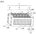
- FIG. 1 is an external perspective view of an assembled battery of Example 1 of the present invention.
- the assembled battery 1 has a battery stack 4 in which a plurality of secondary batteries 3 are stacked and an integrated mechanism 5 that integrates the battery stack.
- the battery stack 4 includes a plurality of secondary batteries 3 and a plurality of battery holders 14 provided between the secondary batteries 3.
- each secondary battery 3 is a flat rectangular prismatic secondary battery having a pair of wide surfaces and two sets of narrow surfaces (one set of two sets of narrow surfaces is a battery lid). And battery bottom).
- the plurality of secondary batteries 3 constituting the battery stack are stacked so that the wide surface sides of the adjacent secondary batteries 3 face each other.
- Adjacent secondary batteries 3 are arranged with their directions reversed so that the positions of the positive terminal and the negative terminal provided on the battery lid are reversed.
- the positive electrode terminal and negative electrode terminal of each adjacent secondary battery 3 are electrically connected by a bus bar 6 ⁇ / b> A that is a metal plate-like conductive member.
- the plurality of secondary batteries 3 constituting the assembled battery according to the present embodiment are electrically connected in series.
- the terminal bus bar 6B is provided in the battery of the both ends of a battery laminated body, and a terminal bus bar is used in order to charge / discharge the whole assembled battery.
- the battery stack 4 is held by the integration mechanism 5.
- the integration mechanism 5 includes a pair of end plates 12 positioned on both ends in the stacking direction of the secondary battery 3 and a pair of side frames 13 positioned on the side surfaces in the stacking direction. A plurality of secondary batteries 3 arranged in a stacked manner are secured.
- the end plate 12 has a rectangular flat plate shape and is formed to have approximately the same size as the secondary battery 3. The pair of end plates sandwich the battery stack 4 from the stacking direction.
- the material of the end plate is a metal such as aluminum or aluminum alloy.
- the pair of side frames 13 are located on the side surface side of the battery stack, and are arranged symmetrically on the left side and the right side.
- the side frame 13 includes a side plate in which a rectangular flat plate is provided with a rectangular opening 13A, and a bent portion 13B that is bent 90 degrees in the same direction at both front and rear ends of the side plate. It has.
- the side plates extend in parallel with each other between the pair of side surface abutting portions extending in parallel with each other between the front end plate and the rear end plate, and between the upper end and the lower end of the battery stack. It has a pair of existing engaging portions and has a substantially square shape when viewed from the left-right direction.
- the side frame 13 is manufactured by cutting a metal plate such as a stainless steel plate or a steel plate having a predetermined thickness into a predetermined width, punching the center into a rectangle, and bending the end portion.
- the plurality of secondary batteries 3 are stacked in the front-rear direction via the battery holder 14 to hold the battery stack.
- the material of the battery holder is a resin having insulating properties and heat resistance, such as engineering plastics such as polybutylene terephthalate (PBT) and polycarbonate (PC), rubber, and the like.
- the battery holder includes an intermediate holder 14A disposed between the adjacent secondary batteries 3, a secondary battery 3 disposed at the front end and the end plate, and a secondary battery 3 disposed at the rear end and the end. It consists of the end holder 14B arrange
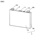
- FIG. 2 is a diagram showing the secondary battery 3.
- the secondary battery 3 includes a rectangular battery container including a battery can 7 and a battery lid 8.
- the material of the battery can and the battery lid is, for example, aluminum or an aluminum alloy.
- the battery can 7 has a rectangular box shape having an opening at one end.
- the battery lid 8 has a rectangular flat plate shape and is laser-welded so as to close the opening of the battery can 7.
- the battery lid 8 seals the battery can 7.
- a rectangular battery container composed of a battery lid and a battery can has a hollow rectangular parallelepiped shape.
- a pair of wide side plates having the largest surface (wide surface 7A) among the side surfaces constituting the battery case are opposed to each other, and the surface having the smallest area (narrow among the side surfaces constituting the battery case).
- a pair of narrow side plates having side surfaces 7B) are opposed to each other, and the battery lid and the bottom plate of the battery can are opposed to each other.
- the secondary battery 3 has a positive terminal and a negative terminal on one side.
- the battery lid 8 is provided with a positive electrode terminal 9A and a negative electrode terminal 9B.
- a charge / discharge element in which a positive electrode and a negative electrode are stacked is housed in a state covered with an insulating case.
- the positive electrode is connected to the positive electrode terminal 9A inside the battery, and the negative electrode is connected to the negative electrode terminal 9B inside the battery.
- the battery lid 8 is provided with a liquid injection hole for injecting an electrolytic solution into the battery container.
- the liquid injection hole is sealed by the liquid injection stopper 10 after the electrolytic solution is injected.
- the electrolytic solution for example, a non-aqueous electrolytic solution in which a lithium salt such as lithium hexafluorophosphate (LiPF6) is dissolved in a carbonic acid ester-based organic solvent such as ethylene carbonate can be used.
- a gas discharge valve 11 is provided on the battery lid. The gas discharge valve 11 is formed by partially thinning the battery lid by press working.
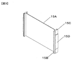
- FIG. 3 is an external perspective view of the intermediate holder 14A.
- the intermediate holder 14A has a separating portion 15A, a connecting portion 15B, a connecting portion 15C, and a convex portion 15D.
- the isolation part 15A opposes the wide surface 7A of the battery and prevents the adjacent wide surfaces 7A of the two batteries from coming into contact with each other.
- the connecting portion 15B has a peak portion, and the connecting portion 15C has a trough portion, and is used for connecting to an adjacent battery holder.
- the convex portion 15D protrudes on the side opposite to the narrow side surface 7B of the battery, and is used when integrating the battery stack as will be described later.
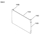
- FIG. 4 is an external perspective view of the end holder 14B.
- the end holder 14B has a separating portion 16A, a connecting portion 16B, a connecting portion 16C, and a convex portion 16D.
- the isolation part 16A opposes the wide surface 7A of the battery and the end plate, and prevents the wide surface 7A of the battery from contacting the end plate.
- the connecting portion 16B has a peak portion, and the connecting portion 16C has a trough portion, and is used for connecting with an adjacent battery holder.
- the convex portion 16D protrudes on the opposite side to the narrow side surface 7B of the battery, and is used when integrating the battery stack as described later.
- Adjacent intermediate holders or intermediate holders and end holders are connected by fitting the connecting portions of the battery holders. Specifically, the intermediate holder connecting portion 15B and the adjacent intermediate holder connecting portion 15C are fitted to each other so that the adjacent intermediate holders are connected to each other, and the intermediate holder connecting portion 15B and the end holder connecting portion 16C are connected. The intermediate holder and the end holder are connected by fitting the connecting portion 15C of the intermediate holder and the connecting portion 16B of the end holder.
- the pair of end plates 12 are arranged on both sides of the battery stack 4.
- the connecting part of the battery holder is connected, and the convex part 15D of the intermediate holder and the convex part 16D of the end holder are convex in the shape of a rectangular parallelepiped facing the opposite side to the narrow side surface 7B of the secondary battery 3 as a whole.
- the opening 13A of the side frame is fitted into this convex portion.
- the opening of the side frame is provided corresponding to the shape of the outer shape of the rectangular parallelepiped convex portion, and the side surface contact portion is the intermediate holder with the rectangular parallelepiped convex portion being fitted into the opening of the side frame.
- the abutting surface portion and the abutting surface portion of the end holder are in contact with each other.
- the upper and lower opening edges of the opening engage with the upper and lower edges of the protrusion
- the front and rear opening edges of the opening engage with the front and rear edges of the protrusion of the end holder.
- the positions of the plurality of intermediate holders and the end holders in the vertical and front-rear and left-right directions are restricted.
- the position in the front-rear direction of the secondary battery 3 sandwiched between the battery holders is restricted, and the position in the left-right direction of the secondary battery 3 sandwiched between the pair of connecting portions of the battery holder is restricted.
- the wide surface contact portion and the wide side plate of the secondary battery 3 are in contact with each other, the inner side surface of the connecting portion and the narrow side plate of the secondary battery 3 are in contact with each other.
- the vertical position of the secondary battery 3 is restricted.
- the method of fixing the side frame to the end plate using screws has been described.
- the side frame is fixed to the end plate using bolts, rivets, or the like, or by caulking or welding. May be.
- the battery part is completed by electrically connecting the positive electrode terminal and the negative electrode terminal of each adjacent secondary battery 3 by a bus bar which is a metal plate-like conductive member.
- a short-circuit member is connected to the battery part thus manufactured.
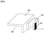
- FIG. 5 shows the structure of the short-circuit member 2 of the first embodiment.
- the positive electrode charging part is a part electrically connected to the positive electrode, and is a positive electrode terminal itself or a bus bar or the like electrically connected to the positive electrode terminal.
- the negative electrode charging portion is a portion electrically connected to the negative electrode, such as the negative electrode terminal itself or a bus bar electrically connected to the negative electrode terminal.
- the short-circuit member 2 has a bow-like thermally responsive part 2A, a base part 2B, and a contact assisting part 2C.
- the thermally responsive part 2A and the base material part 2B, and the thermally responsive part 2A and the contact auxiliary part 2C are integrated and electrically connected.
- the thermally responsive part 2A is made of a conductive member whose shape changes due to heat.
- the thermally responsive portion is a conductive member whose shape changes with heat, and is a bimetal or a shape memory alloy.
- the temperature (operating temperature) at which the thermally responsive portion operates to form a short circuit varies depending on the constituent material of the battery, the operating temperature is preferably 80 ° C. to 100 ° C. or higher.
- a bimetal composed of at least two expansion layers, a high expansion layer and a low expansion layer, is preferable.
- a high expansion layer is made of an alloy of any three of nickel, iron, manganese, and chromium
- a low expansion layer is made of an alloy of any two of nickel, iron, or chromium. it can.
- an expansion layer is not limited to two, You may make it three or more layers.
- a nickel-titanium alloy, a nickel-titanium-cobalt alloy, or the like can be used. The above is preferable.
- the base part 2B is a member that is inferior in conductivity to the thermally responsive part 2A.
- the base material part 2B is not necessarily required, it is provided between the thermally responsive part and the charging part, and the current flowing through the thermally responsive part can be controlled.
- the lower surface 2D of the base material part 2B is electrically connected to the charging part.
- the contact assistant 2C is a conductive member made of a soft metal such as copper. The contact assistant 2C is not necessarily required, but assists the electrical connection between the thermally responsive part when it moves and contacts the opposite charging part.
- the heat-responsive portion 2A moves in the horizontal direction with respect to the lower surface 2D of the base material portion when the shape changes due to heat.
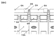
- FIG. 6 is a diagram of the assembled battery 1 provided with the short-circuit member 2.
- Adjacent secondary batteries 3 are stacked with their wide surfaces facing each other, and a plurality of secondary batteries 3 are connected to each other so that the adjacent secondary batteries 3 are connected in a positive electrode terminal 9A and a negative electrode terminal 9B. Connected by busbar.
- busbar Connected by busbar.
- a short-circuit member 2 is provided at a location not connected by the bus bar 6A.
- the short-circuit member 1 is electrically connected to either the positive electrode charging portion or the negative electrode charging portion when the secondary battery 3 is lower than a predetermined temperature.
- the bus bar 6A is provided on the positive electrode terminal 9A side.
- the positive terminal 9A and the negative terminal 9B that are not electrically connected by the bus bar 6A are not electrically connected, but the temperature of the secondary battery 3 is equal to or higher than a predetermined value.
- the heat-responsive portion 2A is deformed and the positive electrode terminal 9A and the negative electrode terminal 9B are in electrical contact, thereby forming a short circuit.
- the predetermined value is a temperature at which the thermally responsive portion 2A is deformed, and the material and structure forming the thermally responsive portion 2A, for example, the layer thickness and material of the above-described high expansion layer and low expansion layer are changed. Adjustment can be made as appropriate.
- means for using a conductive binder such as welding or solder for electrical connection between the thermally responsive part 2A and the base part 2B, the thermally responsive part 2A and the contact assisting part 2C, and the equipment part 2B and the charging part. Can be applied.
- the arc-shaped thermally responsive portion moves in the horizontal direction of the positive electrode charged portion and the negative electrode charged portion, and the charged portion that has not been in electrical contact with the short-circuit member until now. And the short-circuit member are in contact with each other and the adjacent batteries are electrically connected.
- the direction in which the short-circuit member moves is not limited to the horizontal direction of the positive electrode charging portion and the negative electrode charging portion.
- the short-circuit member may move in the height direction of the positive electrode charging portion and the negative electrode charging portion.
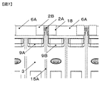
- a resistor 18 can be provided at a location that is electrically separated from the thermal actuator when the temperature is lower than the operating temperature.
- a short circuit is formed between the adjacent secondary batteries 3 by the short circuit member at a high temperature. For this reason, at the time of high temperature, it can discharge between adjacent batteries and can reduce the charge amount of a battery. As a result, an excessively high temperature can be prevented.
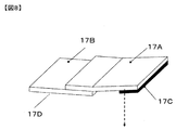
- FIG. 8 is an external perspective view of the short-circuit member 2 according to the second embodiment.
- the short-circuit member 2 includes a base material portion 17B provided with a plate-like heat-responsive portion 17A and a heat-responsive portion 17A, and a contact assisting portion 17C.
- the temperature of the secondary battery 3 is sensed by the lower surface 17D of the base material portion 17B, and the heat responsive portion 17A moves in the direction of the dotted arrow by the heat.
- FIG. 9 is an external view of the assembled battery 1 having the short-circuit member 2 of the second embodiment.
- the short-circuit member 2 is installed between the positive electrode charging portion and the negative electrode charging portion that are not connected by the bus bar 6A, and the battery lid of the secondary battery 3 and the battery lid direction are defined as the height direction.
- the short-circuit member is provided on the height direction side of the positive electrode charging portion and the negative electrode charging portion.
- the short-circuit member 2 is provided on the base portion 17B of the short-circuit member 2 on the positive electrode terminal 9A side of the bus bar 6A.
- the temperature of the secondary battery 3 is sensed by the lower surface 17D of the base material part 17B, and the heat responsive part 17A comes into contact with the bus bar provided on the negative electrode terminal 9B of the adjacent secondary battery 3 by the heat. Is in the height direction (deformed from the upper side to the lower side of the negative terminal) to form a short circuit.
- the assembled battery according to the present embodiment has the same structure as that of the assembled battery of Example 1 except for the configuration of the short-circuit member, the description of overlapping points is omitted.
- the heat generated in the secondary battery 3 is generated in a large amount in the positive electrode, the negative electrode, the positive electrode current collector connecting the positive electrode and the positive electrode terminal, and the negative electrode current collector connecting the negative electrode and the negative electrode terminal.
- FIG. 10 is an external perspective view of the short-circuit member 2 according to the third embodiment.
- the short-circuit member 2 has a thermally responsive part 19A, a base part 19B, and a contact assisting part 19C.
- a bifurcated thermally responsive portion 19A is provided at the end of the plate-like base material portion 19B, and each thermally responsive portion 19A moves in the direction opposite to the wide surface direction of the base material portion 19B (in the direction of the dotted arrow in the figure). be able to.
- the thermally responsive portion 19A and the base material portion 19B, and the thermally responsive portion 19A and the contact assisting portion 19C are integrated and electrically connected.
- the thermally responsive portion 19A is made of a conductive member whose shape changes with heat.
- the base material portion 19B is a heat conductor such as metal.
- the base material portion 19B is thermally connected to the battery can.
- the base material portion 19B is not always necessary, and the heat responsive portion may be directly connected to the battery can.
- the contact assistant 19C is a conductive member made of a soft metal such as copper.
- the contact assisting part 19C is not necessarily required, but assists the electrical connection between the thermally responsive part when it moves and contacts the opposing charging part.
- the heat-responsive portion 19A moves in a direction perpendicular to the base material portion 19B when the shape changes due to heat.
- FIG. 11 is an external view of the assembled battery 1 having the short-circuit member 2 according to the third embodiment.
- the short-circuit member 2 is provided between the positive electrode charging portion and the negative electrode charging portion that are not connected by the bus bar 6A.
- the base material portion 19B is provided between the wide surfaces of the adjacent secondary batteries 3.
- the base material portion 19B is provided in a state of being in thermal contact with the wide surface of the secondary battery 3 in order to transmit the heat of the secondary battery 3 to the heat responsive portion 19A.
- the base material portion 19B may be in contact with two adjacent secondary batteries 3 or one of them.
- the short-circuit member 2 contacts the positive electrode charging portion and the negative electrode charging portion to form a short circuit. Since the short circuit can be formed by detecting the temperature of the surface of the battery can, an excessive temperature rise of the battery can be prevented.
- this embodiment can catch the heat of the wide surface of the battery can, it can catch the heat fluctuation of a wider area.
- FIG. 12 is an external perspective view of the short-circuit member 2 according to the fourth embodiment.
- the short-circuit member 2 has a thermally responsive part 20A, a base part 20B, and a contact assisting part 20C.
- the thermally responsive portion 20A and the base material portion 20B, and the thermally responsive portion 20A and the contact assisting portion 20C are integrated and electrically connected.
- the block-like base material portion 20B is provided with a U-shaped plate-like heat responsive portion 20A, and a contact assisting portion 20C is provided at the end of the heat responsive portion 20A.
- the base material portion 20B is thermally connected to the battery lid.
- the base material portion 19B is not necessarily required, and the heat responsive portion may be directly connected to the battery can.
- the contact assistant 20C is electrically connected to the thermally responsive part 20A.
- the contact assistant 20C is not always necessary, but assists the electrical connection between the thermally responsive part when it moves and contacts the opposite charging part. The heat is transferred from the base material portion 20B that has received heat to the heat responsive portion 20A, and the heat responsive portion 20A is deformed by sensing the heat.
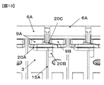
- FIG. 13 is an external view of the assembled battery 1 having the short-circuit member 2 according to the fourth embodiment.
- the short-circuit member 2 is also provided with a position corresponding to the horizontal direction (direction along the battery lid) of the positive electrode charging portion and the negative electrode charging portion that are not connected by the bus bar 6A between the adjacent secondary batteries 3.
- the base material portion 20 ⁇ / b> B is provided on the battery lid of the secondary battery 3.
- the base material portion 20B is provided in a state of being in thermal contact with the battery lid in order to transmit the heat of the secondary battery 3 to the heat responsive portion 20A.
- the contact assisting unit 20C may be in contact with either the positive electrode charging unit or the negative electrode charging unit at a low temperature, or may be in a state separated from both.
- the contact assisting unit 20C includes the secondary battery 3. Is provided only in contact with the positive electrode terminal 6A at low temperatures. When the secondary battery 3 exceeds a predetermined temperature, the thermally responsive part 20A is deformed, and the contact auxiliary part 20C electrically connects the positive electrode terminal 9A as the positive electrode charging part and the negative electrode terminal 9B as the negative electrode charging part.
- the short-circuit member 2 is provided on the lid as in the fourth embodiment, since the base material portion 20B can be provided at any location on the lid wider than the charging portion, there is a good improvement in design flexibility. .
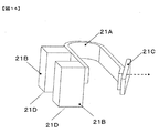
- FIG. 14 is an external perspective view of the short-circuit member 2 according to the fifth embodiment.
- Example 5 the short-circuit member is connected to the two adjacent secondary batteries 3 in Example 4, and when either battery reaches a predetermined temperature or more, it is detected and the short-circuit member operates. It is a thing.
- the short-circuit member 2 is provided with two base parts 21B on a U-shaped plate-like heat-responsive part 20A.
- a contact assisting portion 21C is provided at the end of the thermally responsive portion 20A on the side where the base material portion 21B is not provided, as in the fourth embodiment.
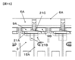
- FIG. 15 is an external view of the assembled battery 1 having the short-circuit member 2 according to the fifth embodiment.
- the short-circuit member 2 is provided at a position facing the positive electrode charging portion and the negative electrode charging portion that are not connected by the bus bar 6A between the adjacent secondary batteries 3.
- the base material portion 21B is provided in a state of being in thermal contact with the battery lid in order to transmit the heat of the secondary battery 3 to the heat responsive portion 20A.
- the base material portion 21 ⁇ / b> B is provided on the lid of each secondary battery 3 in order to sense the heat of any of the adjacent secondary batteries 3.
- the short circuit can be formed by detecting the temperature of the surface of the battery lid, it is possible to prevent an excessive temperature rise of the battery.
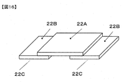
- FIG. 16 is an external perspective view of the short-circuit member 2 according to the sixth embodiment.
- the short-circuit member 2 has a resistance change portion 22A and two base material portions 22B.
- the resistance change portion 22A and the base material portion 22B are in contact with each other.
- the resistance changing portion 22A has a characteristic that the resistance value changes according to the temperature, and the resistance value decreases as the temperature increases. For this reason, the two base material portions 22B are not electrically connected at a low temperature, and the resistance of the resistance change portion 22A is lowered and electrically connected due to the high temperature.
- the resistance change portion 22A As a material of the resistance change portion 22A, ceramics including manganese, nickel, cobalt, iron, vanadium oxide, or the like can be used.
- the base material portion 22B is a heat conductor such as metal.
- the lower surface 22C of the base material portion 22B is electrically connected to the charging portion.
- the positive electrode terminal and the negative electrode terminal may be connected to each other, or the bus bar provided to the positive electrode terminal and the bus bar provided to the negative electrode terminal may be connected to each other.
- the base material portion 22B is not necessarily required, and the resistance change portion may be directly connected to the charging portion.
- FIG. 17 is an external view of the assembled battery 1 having the short-circuit member 2 of Example 6.
- the short-circuit member 2 includes a positive electrode charging portion and a negative electrode charging portion (a bus bar 6A provided at the positive electrode terminal 9A and a bus bar 6A provided at the negative electrode terminal 9B) in which the adjacent secondary batteries 3 are not connected by the bus bar 6A. Connected.
- the positive electrode charging portion and the negative electrode charging portion are not electrically connected.
- the resistance of the resistance change portion 22A decreases, and the positive electrode charging portion and the negative electrode charging portion are electrically connected. Since the positive electrode charging portion and the negative electrode charging portion are electrically connected to each other, a short circuit can be formed, so that excessive heat generation of the secondary battery 3 can be avoided.
- the short-circuit member of Example 6 does not require a change in shape due to temperature rise, the shape of the short-circuit member can be simplified. For this reason, even if the shape slightly changes due to external impact or the like, the role as a short-circuit member is easily maintained.
Landscapes
- Chemical & Material Sciences (AREA)
- Chemical Kinetics & Catalysis (AREA)
- Electrochemistry (AREA)
- General Chemical & Material Sciences (AREA)
- Inorganic Chemistry (AREA)
- Physics & Mathematics (AREA)
- Thermal Sciences (AREA)
- Connection Of Batteries Or Terminals (AREA)
- Thermally Actuated Switches (AREA)
- Battery Mounting, Suspending (AREA)
Abstract
確実な動作で高温状態の電池の充電量を減らすことが可能な組電池を提供する。一対の幅広面と、対向する二組の幅狭面と、を有する電池容器と、前記幅狭面のいずれかに設けられた正極端子と負極端子と、を有する二次電池を複数有し、複数の前記二次電池は、前記幅広面を対向して積層され、複数の前記二次電池は、直列接続となるように隣り合う前記二次電池同士が、前記正極端子と前記負極端子とがバスバーにより接続された組電池において、前記二次電池は、前記二次電池の温度の上昇に応じてバスバーが設けられていない前記正極荷電部と負極荷電部との間を通電する短絡部材を有する。
Description
本発明は、リチウムイオン電池モジュールに関する。
リチウムイオン電池は、過充電、加熱等により過剰に高温になる場合がある。このような高温の状態では充電時における電極活物質や電解液の不安定性が増すため、充電量が多いほど発火等の可能性が高くなる。
特に、近年、電気自動車等の動力として、複数のリチウムイオンを連結したリチウムイオン電池モジュール(組電池)の開発が進められている。組電池では、発火が生じた場合の被害が二次電池3と比較して更に大きくなるため、組電池を対象とする高温状態のリチウムイオン電池の充電量を減らす手段が必要となっている。
特許文献1には、組電池を構成するリチウムイオン電池の充電量を減らす手段として、隣接する電池の正極端子と負極端子とを電気的に接続するバスバー同士を接触させて短絡回路を形成する構成が開示されている。
特許文献1に記載の組電池は、組電池の変形を利用して短絡回路を形成するため、組電池の変形を伴わずに電池が高温になる場合には効果が期待できない。また、組電池の変形は衝突や圧縮等の外的な要因によるものであるため、変形形状を管理することは困難であり、場合によってはバスバー同士が接触せずに短絡回路が形成されないことも起こり得る。
本発明は、前記課題に鑑みてなされたものであり、その目的とするところは、外圧や電池の変形を必要とせずに温度上昇により作動することで組電池の過剰な温度上昇を防ぐ構造を提供することにある。
本発明の課題を解決する手段は例えば以下である。
一対の幅広面と、対向する二組の幅狭面と、を有する電池容器と、前記幅狭面のいずれかに設けられた正極端子と負極端子と、を有する二次電池を複数有し、複数の前記二次電池は、前記幅広面を対向して積層され、複数の前記二次電池は、直列接続となるように隣り合う前記二次電池同士が、前記正極端子と前記負極端子とがバスバーにより接続され、隣り合う一組の前記二次電池は、積層方向に対向して配置された二組の前記正極端子と前記負極端子を有し、一方組の前記正極端子と前記負極端子は、前記バスバーにより接続され、他一方組の前記正極端子と前記他一方組の前記正極端子に設けられた前記バスバーとからなる正極荷電部と、他一方組の前記負極端子と前記他一方組の前記負極端子に設けられた前記バスバーとからなる負極荷電部とは、電気的に接続されていない組電池において、前記二次電池は、前記二次電池の温度の上昇に応じて前記正極荷電部と負極荷電部との間を通電する短絡部材を有する組電池。
本発明により、外圧や電池の変形を必要とせずに温度上昇により作動することで組電池の過剰な温度上昇を防ぐ構造を提供することができる。
以下、図面を参照して、本発明を実施するための最良の形態を具体的な実施例によって説明するが、本発明はこれに限定されるものではなく、本発明の技術的思想の範囲内で考えられるその他の形態についても本発明の範囲内に含まれる。また、実施例における図は、略図であり、図中の位置関係系や寸法等に正確さを保証するものではない。本明細書に開示される技術的思想の範囲内において当業者による様々な変更および修正が可能である。また、本発明を説明するための全図において、同一の機能を有するものは、同一の符号を付け、その繰り返しの説明は省略する場合がある。
(実施例1)
図1は本発明の実施例1の組電池の外観斜視図である。
図1は本発明の実施例1の組電池の外観斜視図である。
組電池1は、複数の二次電池3が積層配置された電池積層体4と、その電池積層体を一体化する一体化機構5を有する。
電池積層体4は、複数の二次電池3と、二次電池3の間に設けられた複数の電池ホルダ14とを備えている。本実施例において各二次電池3は、扁平な直方体形状の角型二次電池であって、一対の幅広面、二組の幅狭面(二組の幅狭面のうち一組は電池蓋と電池底面)を有している。電池積層体を構成する複数の二次電池3は、隣り合う二次電池3の互いの幅広面側同士が対向するように積層配置されている。隣接する二次電池3同士は、電池蓋に設けられた正極端子および負極端子の位置が逆転するように、向きが反転して配置されている。隣り合う各二次電池3の正極端子と負極端子とは金属製の平板状導電部材であるバスバー6Aによって電気的に接続されている。本実施の形態に係る組電池を構成する複数の二次電池3は、電気的に直列に接続されている。また、電池積層体の両端の電池には端子バスバー6Bが備えられており、端子バスバーは組電池全体を充放電するために使用される。
電池積層体4は、一体化機構5により保持されている。一体化機構5は、二次電池3の積層方向両端側に位置する一対のエンドプレート12と、積層方向の側面側位置する一対のサイドフレーム13とを含んで構成され、電池ホルダ14を介して積層配置された複数の二次電池3を固縛している。エンドプレート12は、矩形平板状であり、二次電池3とほぼ同じ大きさに形成されている。一対のエンドプレートは、電池積層体4を積層方向のから挟持している。エンドプレートの材質は、アルミニウムやアルミニウム合金などの金属である。
一対のサイドフレーム13は、電池積層体の側面側に位置し、左方および右方において、左右対称に配置されている。図1に示すように、サイドフレーム13は、矩形状の平板に矩形状の開口部13Aが設けられた側板と、側板の前後方向両端のそれぞれで同方向に90度屈曲された屈曲部13Bとを備えている。側板は、前側のエンドプレートと後側のエンドプレートとの間に亘って互いに平行に延在する一対の側面当接部と、電池積層体の上端と下端との間に亘って互いに平行に延在する一対の係合部とを備え、左右方向から見たときに略ロ字状を呈している。サイドフレーム13は、所定の厚さのステンレス板や鋼板等の金属板を所定の幅に切り出した後、中央を矩形に打ち抜き、端部を折り曲げ加工して製作される。
複数の二次電池3は、電池ホルダ14を介して、前後方向に積層配置されて電池積層体を保持している。電池ホルダの材質は、絶縁性および耐熱性を有する樹脂であり、たとえば、ポリブチレンテレフタレート(PBT)やポリカーボネイト(PC)等のエンジニアリングプラスチックやゴム等である。電池ホルダは、隣り合う二次電池3間に配置される中間ホルダ14Aと、前端に配置される二次電池3とエンドプレートとの間、および、後端に配置される二次電池3とエンドプレートとの間に配置される端部ホルダ14Bとからなる。各二次電池3同士の間に中間ホルダが介在しているため、隣り合う二次電池3同士の絶縁性が確保されている。エンドプレートと二次電池3との間に端部ホルダが介在しているためエンドプレートと二次電池3との絶縁性が確保されている。
図2は、二次電池3を示す図である。
二次電池3は、電池缶7と電池蓋8とからなる角形の電池容器を備えている。電池缶および電池蓋の材質は、たとえばアルミニウムやアルミニウム合金である。電池缶7は、一端に開口部を有する矩形箱状とされる。電池蓋8は、矩形平板状であって、電池缶7の開口部を塞ぐようにレーザ溶接されている。電池蓋8は、電池缶7を封止している。電池蓋と電池缶とからなる角形の電池容器は、中空の直方体形状とされている。電池容器は、電池容器を構成する側面のうちで最も面積の大きい面(幅広面7A)を有する一対の幅広側板同士が対向し、電池容器を構成する側面のうちで最も面積の小さい面(狭側面7B)を有する一対の幅狭側板同士が対向し、電池蓋と電池缶の底板とが対向している。
二次電池3は一面に正極端子および負極端子を有する。本実施例においては、電池蓋8には、正極端子9Aおよび負極端子9Bが設けられている。電池容器の内部には、正極、負極を積層した充放電要素が絶縁ケースに覆われた状態で収納されている。正極は電池内部で正極端子9Aと接続され、負極は電池内部で負極端子9Bと接続されている。
電池蓋8には、電池容器内に電解液を注入するための注液孔が穿設されている。注液孔は、電解液注入後に注液栓10によって封止される。電解液としては、たとえば、エチレンカーボネート等の炭酸エステル系の有機溶媒に6フッ化リン酸リチウム(LiPF6)等のリチウム塩が溶解された非水電解液を用いることができる。電池蓋には、ガス排出弁11が設けられている。ガス排出弁11は、プレス加工によって電池蓋を部分的に薄肉化することで形成されている。ガス排出弁11は、二次電池3が過充電等の異常により発熱してガスが発生し、電池容器内の圧力が上昇して所定圧力に達したときに開裂して、内部からガスを排出することで電池容器内の圧力を低減させる。
図3は中間ホルダ14Aの外観斜視図である。
図3は中間ホルダ14Aの外観斜視図である。
中間ホルダ14Aは、隔離部15A、連結部15B、連結部15C、凸部15Dを有する。隔離部15Aは電池の幅広面7Aに対抗し、隣接する二個の電池の幅広面7Aが当接することを防止する。連結部15Bは山部を、連結部15Cは谷部を有し、隣接する電池ホルダと連結するために使用される。凸部15Dは、電池の狭側面7Bとは反対側に突き出しており、後述のように、電池積層体を一体化するときに使用される。
図4は端部ホルダ14Bの外観斜視図である。
端部ホルダ14Bは、隔離部16Aと連結部16B、連結部16C、凸部16Dを有する。隔離部16Aは電池の幅広面7Aとエンドプレートに対抗し、電池の幅広面7Aとエンドプレートが当接することを防止する。連結部16Bは山部を、連結部16Cは谷部を有し、隣接する電池ホルダと連結するために使用される。凸部16Dは、電池の狭側面7Bとは反対側に突き出しており、後述のように、電池積層体を一体化するときに使用される。
隣接する中間ホルダ同士、あるいは中間ホルダと端部ホルダとは、各電池ホルダの連結部を嵌合することで連結される。具体的には、中間ホルダの連結部15Bと隣接する中間ホルダの連結部15Cを嵌合することで、隣接する中間ホルダ同士は連結され、中間ホルダの連結部15Bと端部ホルダの連結部16C、および中間ホルダの連結部15Cと端部ホルダの連結部16Bとを嵌合することで、中間ホルダと端部ホルダは連結される。
(電池積層体の一体化方法)
初めに、一対のエンドプレート12を電池積層体4の両側に配置する。この時、電池ホルダの連結部が連結されて、中間ホルダの凸部15Dおよび端部ホルダの凸部16Dは、全体として二次電池3の狭側面7Bとは反対側へ向いた直方体形状の凸部を構成している。次に、この凸部に、サイドフレームの開口部13Aを嵌入させる。サイドフレームの開口部は、直方体形状の凸部の外形の形状に対応して設けられており、サイドフレームの開口部に直方体形状の凸部が嵌入された状態で、側面当接部が中間ホルダの当接面部および端部ホルダの当接面部に当接される。開口部における上下の開口縁部は、凸部の上下の縁部に係合し、開口部における前後の開口縁部は、端部ホルダの凸部の前後の縁部に係合する。最後に、サイドフレームの屈曲部13Bをねじによりエンドプレートにねじ止めする
。サイドフレームの屈曲部13Bがエンドプレートにねじ止めされると、一対のエンドプレートに挟まれた電池ホルダおよび二次電池3が所定量圧縮された状態で保持される。このように、一体化機構により電池積層体が固縛されると、複数の中間ホルダおよび端部ホルダの上下および前後左右方向の位置が規制される。その結果、電池ホルダに挟まれる二次電池3の前後方向の位置が規制され、電池ホルダの一対の連結部に挟まれる二次電池3の左右方向の位置が規制される。また、幅広面当接部と二次電池3の幅広側板とが当接され、連結部の内側面と二次電池3の幅狭側板とが当接されているため、接触面における摩擦力により、二次電池3の上下方向の位置が規制される。なお、本実施の形態では、ねじを用いてサイドフレームをエンドプレートに固定する方法について説明したが、ボルト、リベットなどを用いて、あるいは、かしめ、溶接などにより、サイドフレームをエンドプレートに固定してもよい。
この状態で隣り合う各二次電池3の正極端子と負極端子とを金属製の平板状導電部材であるバスバーによって電気的に接続することで、電池部が完成する。次に、このようにして作製した電池部に短絡部材を接続する。
図5は実施例1の短絡部材2の構造である。
なお、以下説明に当たり、便宜上、正極荷電部と負極荷電部という用語を定義して用いる。正極荷電部は、正極と電気的に接続されている部位であり、正極端子それ自体あるいは正極端子と電気的に接続されたバスバー等である。負極荷電部は負極と電気的に接続されている部位であり、負極端子それ自体あるいは負極端子と電気的に接続されたバスバー等である。
短絡部材2は弓状の熱応動部2Aと基材部2Bと接触補助部2Cを有す。熱応動部2Aと基材部2B、熱応動部2Aと接触補助部2Cはそれぞれ一体化されて電気的に接続されている。熱応動部2Aは熱によって形状が変化する導電性部材からなる。
ここで、熱応動部は熱によって形状が変化する導電性部材であり、バイメタルや形状記憶合金である。熱応動部が動作して短絡回路を形成する温度(動作温度)は電池の構成材料によって異なるが、動作温度としては80℃から100℃以上が好ましい。熱応動部としてバイメタルを用いる場合には、高膨張層と低膨張層の少なくとも二つの膨張層からなるバイメタルが好適である。このようなバイメタルとしては、例えば高膨張層がニッケル、鉄、マンガン、クロムのいずれか三種の合金からなり、低膨張層が、ニッケル、鉄、クロムのいずれか二種の合金からなるものを使用できる。なお、膨張層は二つに限定されず、三層以上にしてもよい。熱応動部として形状記憶合金を用いる場合には、ニッケル‐チタン合金、ニッケル‐チタン‐コバルト合金等を用いることができ、熱応動部の動作温度を考慮すると、合金に占めるニッケル成分量は55wt%以上が好ましい。
基材部2Bは熱応動部2Aより導電性が劣る部材である。基材部2Bは必ずしも必要ではないが、熱応動部と荷電部との間に備えられ、熱応動部を流れる電流を制御することができる。基材部2Bの下面2Dは荷電部と電気的に接続されている。接触補助部2Cは銅などの柔らかい金属からなる導電性部材である。接触補助部2Cは必ずしも必要ではないが、熱応動部が動いて、対向する荷電部と接触するとき、その間の電気的な接続を補助する。熱応動部2Aは、熱によって形状が変化する場合には、基材部の下面2Dに対して水平方向に動く。
図6は短絡部材2を設けた組電池1の図である。
隣合う二次電池3同士は幅広面を対向して積層され、複数の二次電池3は、直列接続となるように隣り合う前記二次電池3同士が、正極端子9Aと負極端子9Bとがバスバーにより接続されている。ここで、隣り合う二つ(一組)の二次電池3に注目すると、積層方向に対向して配置された二組の正極端子9Aと負極端子9Bを有し、一方組の正極端子9Aと負極端子9Bは、バスバー6Aにより接続され、他一方組の正極端子9Aと負極端子9Bはバスバー6Aにより接続されていない。このバスバー6Aにより接続されていない箇所には短絡部材2が設けられている。
短絡部材1は、二次電池3が所定の温度より低い状態では、正極荷電部あるいは負極荷電部のどちらか一方と電気的に接続されている。本実施例においては、バスバー6Aのうち正極端子9A側に設けられている。二次電池3の温度が所定より低い場合はバスバー6Aにより電気的に接続されていない正極端子9Aと負極端子9Bは電気的に接続されていないが、二次電池3の温度は所定値以上になった場合、熱応動部2Aが変形して正極端子9Aと負極端子9Bが電気的に接触することで短絡回路が形成される。ここで、所定値とは、熱応動部2Aが変形する温度であり、熱応動部2Aを形成する材料や構造、例えば前述した高膨張層、低膨張層の層厚、材料を変更することで適宜調節が可能である。
ここで、熱応動部2Aと基材部2B、熱応動部2Aと接触補助部2C、機材部2Bと荷電部の電気的な接続には、溶接やハンダ等の導電性結着剤を用いる手段を適用することができる。この状態で電池が所定の温度以上になると、弓状の熱応動部が正極荷電部と負極荷電部の水平方向に動いて、これまで短絡部材と電気的に接触していなかった方の荷電部と短絡部材とが接触して隣り合う電池同士が電気的に接続される。
また、短絡部材が動く方向は正極荷電部と負極荷電部の水平方向に限定されない。短絡部材は、正極荷電部と負極荷電部の高さ方向に動いてもよい。
また、短絡部材を流れる電流を制限するために、図7に示すように、動作温度より低い状態では熱応動部と電気的に離れている場所に、抵抗体18を備えることもできる。
以上説明した本実施の形態によれば、以下のような作用効果を奏することができる。本実施の形態では、高温において、短絡部材によって、隣り合う二次電池3間に短絡回路が形成される。このため、高温時には隣り合う電池間で放電して、電池の充電量を減らすことができる。その結果、過剰な高温を防ぐことができる。
(実施例2)
図8は実施例2の短絡部材2の外観斜視図である。
図8は実施例2の短絡部材2の外観斜視図である。
短絡部材2は、板状の熱応動部17Aと熱応動部17Aが設けられた基材部17Bと接触補助部17Cを有する。基材部17Bの下面17Dにて二次電池3の温度を感知し、その熱により熱応動部17Aが点線矢印の方向に動く。
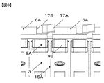
図9は実施例2の短絡部材2を有する組電池1の外観図である。
短絡部材2は実施例1と同様に、バスバー6Aにより接続されていない正極荷電部と負極荷電部との間に設置されており、二次電池3の電池蓋、電池蓋方向を高さ方向とした場合に正極荷電部と負極荷電部の高さ方向側に短絡部材が位置するように設けられている。短絡部材2の基材部17Bはバスバー6Aの正極端子9A側に短絡部材2が設けられている。基材部17Bの下面17Dにて二次電池3の温度を感知し、その熱により熱応動部17Aが隣り合う二次電池3の負極端子9Bに設けられたバスバーに接触することで、短絡部材が高さ方向(負極端子の上側から下側に変形)することで短絡回路が形成される。
本実施形態による組電池は、短絡部材の構成を除いては、実施例1の組電池と同様な構造であるため重複する点は説明を省略する。
二次電池3の内部の熱は正極電極、負極電極、正極電極と正極端子を繋ぐ正極集電体、負極電極と負極端子を繋ぐ負極集電体にて発生する量が多い為、実施例1、実施例2のようにより電池内部の熱を反映しやすいように荷電部に短絡部材2を設けることで、二次電池3の熱上昇をより敏感に捉えることができる。
(実施例3)
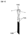
図10は実施例3の短絡部材2の外観斜視図である。
図10は実施例3の短絡部材2の外観斜視図である。
短絡部材2は、熱応動部19Aと基材部19Bと接触補助部19Cを有する。
板状の基材部19Bの端部には二股の熱応動部19Aが設けられ、それぞれの熱応動部19Aは、基材部19Bの幅広面方向の逆方向(図中点線矢印方向)に動くことができる。
熱応動部19Aと基材部19B、熱応動部19Aと接触補助部19Cはそれぞれ一体化されて電気的に接続されている。熱応動部19Aは熱によって形状が変化する導電性部材からなる。基材部19Bは金属等の熱伝導体である。基材部19Bは電池缶と熱的に接続されている。基材部19Bは必ずしも必要ではなく、電池缶に直接熱応動部を接続してもよい。接触補助部19Cは銅などの柔らかい金属からなる導電性部材である。接触補助部19Cは必ずしも必要ではないが、熱応動部が動いて、対向する荷電部と接触するとき、その間の電気的な接続を補助する。熱応動部19Aは、熱によって形状が変化する場合には、基材部19Bに対して垂直方向に動く。
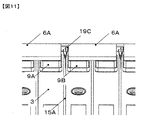
図11は、実施例3の短絡部材2を有する組電池1の外観図である。
短絡部材2は、実施例1と同様に、バスバー6Aにより接続されていない正極荷電部と負極荷電部との間に設けられる。基材部19Bは隣り合う二次電池3の幅広面同士の間に設けられる。基材部19Bは二次電池3の熱を熱応動部19Aに伝えるために二次電池3の幅広面と熱的に接触した状態で設けられる。基材部19Bは、隣り合う二つの二次電池3両方に接触してもよいし、片方でも良い。
熱応動部19Aが熱を感知し、変形すると、短絡部材2により正極荷電部と負極荷電部が接触して短絡回路が形成される。電池缶表面の温度を検知して短絡回路を形成させることができるため、電池の過剰な温度上昇を防ぐことができる。
本実施例は電池缶の幅広面の熱を捉えることができるので、より広い面積の熱変動を捉えることができる。
(実施例4)
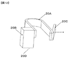
図12は実施例4の短絡部材2の外観斜視図である。
図12は実施例4の短絡部材2の外観斜視図である。
短絡部材2は、熱応動部20Aと基材部20Bと接触補助部20Cを有す。熱応動部20Aと基材部20B、熱応動部20Aと接触補助部20Cはそれぞれ一体化されて電気的に接続されている。ブロック状の基材部20BにはU字板状の熱応動部20Aが設けられ、熱応動部20Aの端部には接触補助部20Cが設けられている。
基材部20Bは電池蓋と熱的に接続されている。ここで、基材部19Bは必ずしも必要ではなく、電池缶に直接熱応動部を接続してもよい。接触補助部20Cは熱応動部20Aと電気的に接続されている。接触補助部20Cは必ずしも必要ではないが、熱応動部が動いて、対向する荷電部と接触するとき、その間の電気的な接続を補助する。熱を受け取った基材部20Bから熱が熱応動部20Aに移動し、その熱を感知して熱応動部20Aは変形する。
図13は、実施例4の短絡部材2を有する組電池1の外観図である。
短絡部材2は、隣り合う二次電池3同士のバスバー6Aにより接続されていない正極荷電部と負極荷電部の水平方向(電池蓋に沿う方向)に対応する位置も設けられている。基材部20Bは二次電池3の電池蓋に設けられる。基材部20Bは二次電池3の熱を熱応動部20Aに伝える為に電池蓋と熱的に接触した状態で設けられる。短絡部材2の温度が所定値以上になると短絡部材2は、変形して正極荷電部と負極荷電部とを電気的に接続する。接触補助部20Cは、低温時には正極荷電部と負極荷電部のいずれかに接触していてもよく、両者から離れた状態でもよい、実施例4においては、接触補助部20Cは、二次電池3が低温時には正極端子6Aにのみ触れた状態で設けられている。二次電池3が所定の温度を越えると熱応動部20Aが変形し、接触補助部20Cにより正極荷電部である正極端子9Aと負極荷電部である負極端子9Bとが電気的に接続される。
実施例4のように、蓋に短絡部材2を設ける場合には、基材部20Bは、荷電部よりも広い蓋のあらゆる場所に備えることができるため、設計の自由度が向上する良さが有る。
(実施例5)
図14は実施例5の短絡部材2の外観斜視図である。
図14は実施例5の短絡部材2の外観斜視図である。
実施例5は、実施例4において短絡部材を隣接する二つの二次電池3に接続して、どちらかの電池が所定の温度以上になった場合にそれを検知して短絡部材が動作するようにしたものである。
短絡部材2は、U字板状の熱応動部20Aに二つの基材部21Bが設けられている。熱応動部20Aの基材部21Bが設けられていない側の端部には、実施例4と同様に接触補助部21Cが設けられている。
図15は、実施例5の短絡部材2を有する組電池1の外観図である。
短絡部材2は、実施例4と同様に、隣り合う二次電池3同士のバスバー6Aにより接続されていない正極荷電部と負極荷電部と対向する位置に設けられている。基材部21Bは二次電池3の熱を熱応動部20Aに伝える為に電池蓋と熱的に接触した状態で設けられる。基材部21Bは隣り合う二次電池3のいずれかの熱を感知するために、それぞれの二次電池3の蓋に設けられている。二次電池3の熱により短絡部材2の温度が所定値以上になると短絡部材2は、変形して正極荷電部と負極荷電部とを電気的に接続し、短絡経路を形成する。
電池蓋表面の温度を検知して短絡回路を形成させることができるため、電池の過剰な温度上昇を防ぐことができる。
(実施例6)
図16は実施例6の短絡部材2の外観斜視図である。
図16は実施例6の短絡部材2の外観斜視図である。
短絡部材2は抵抗変化部22Aと二つの基材部22Bを有する。抵抗変化部22Aと基材部22Bは、接触した状態である。抵抗変化部22Aは温度に応じて抵抗値が変化し、温度が高くなるほど抵抗値が低くなる特性を有する。この為、低温時には二つの基材部22Bは電気的には繋がっておらず、高温になることで抵抗変化部22Aの抵抗が下がり、電気的に繋がる。
抵抗変化部22Aの材料としては、マンガン、ニッケル、コバルト、鉄を含むセラミックス、または、酸化バナジウム等を用いることができる。基材部22Bは金属等の熱伝導体である。基材部22Bの下面22Cは荷電部と電気的に接続されている。正極端子と負極端子とを繋ぐように設けられていてもよいし、正極端子に設けられたバスバーと負極端子に設けられたバスバーを繋ぐように設けてもよい。
ここで、基材部22Bは必ずしも必要ではなく、荷電部に直接抵抗変化部を接続してもよい。
図17は、実施例6の短絡部材2を有する組電池1の外観図である。
短絡部材2は、隣り合う二次電池3同士がバスバー6Aにより接続されていない正極荷電部と負極荷電部(正極端子9Aに設けられたバスバー6Aと負極端子9Bに設けられたバスバー6A)とを繋いで設けられている。
低温時には正極荷電部と負極荷電部とは電気的には繋がっておらず、高温になることで抵抗変化部22Aの抵抗が下がり、正極荷電部と負極荷電部とが電気的に繋がる。正極荷電部と負極荷電部とが電気的に繋がることで短絡回路を形成することができる為、二次電池3の過剰な発熱を回避することができる。
実施例6の短絡部材は、温度上昇による形状の変化を必要としないため、短絡部材の形状がを単純なものとすることができる。この為外部からの衝撃等により多少形状が変化したとしても短絡部材としての役割を保ちやすい。
1 組電池
2 短絡部材
2A 熱応動部
2B 基材部
2C 接触補助部
2D 下面
3 二次電池3
4 電池積層体
5 一体化機構
6A バスバー
6B 端子バスバー
7 電池缶
7A 幅広面
7B 狭側面
8 電池蓋
9A 正極端子
9B 負極端子
10 注液栓
11 ガス排出弁
12 エンドプレート
13 サイドフレーム
13A 開口部
13B 屈曲部
14 電池ホルダ
14A 中間ホルダ
14B 端部ホルダ
15A 隔離部
15B 連結部
15C 連結部
15D 凸部
16A 隔離部
16B 連結部
16C 連結部
16D 凸部
17A 熱応動部
17B 基材部
17C 接触補助部
17D 下面
18 抵抗体
19A 熱応動部
19B 基材部
19C 接触補助部
20A 熱応動部
20B 基材部
20C 接触補助部
20D 下面
21A 熱応動部
21B 基材部
21C 接触補助部
21D 下面
22A 熱応動部
22B 基材部
22C 下面
Claims (18)
- 一対の幅広面と、対向する二組の幅狭面と、を有する電池容器と、
前記幅狭面のいずれかに設けられた正極端子と負極端子と、を有する二次電池を複数有し、
複数の前記二次電池は、前記幅広面を対向して積層され、
複数の前記二次電池は、直列接続となるように隣り合う前記二次電池同士が、前記正極端子と前記負極端子とがバスバーにより接続され、
隣り合う一組の前記二次電池は、積層方向に対向して配置された二組の前記正極端子と前記負極端子を有し、一方組の前記正極端子と前記負極端子は、前記バスバーにより接続され、
他一方組の前記正極端子と前記他一方組の前記正極端子に設けられた前記バスバーとからなる正極荷電部と、他一方組の前記負極端子と前記他一方組の前記負極端子に設けられた前記バスバーとからなる負極荷電部とは、電気的に接続されていない組電池において、前記二次電池は、前記二次電池の温度の上昇に応じて前記正極荷電部と負極荷電部との間を通電する短絡部材を有する組電池。 - 請求項1において、
前記短絡部材は、熱応動部材を有し、
前記短絡部材は、前記二次電池の温度の上昇による前記熱応動部材の変形により、前記正極荷電部と前記負極荷電部とを接続する組電池。 - 請求項2において、
前記短絡部材は、前記正極荷電部または前記負極荷電部に設けられた組電池。 - 請求項3において、
前記短絡部材は、前記正極端子または前記負極端子に設けられた組電池。 - 請求項3において、
前記短絡部材は、前記他一方組の前記正極端子に設けられた前記バスバーまたは、前記他一方組の前記負極端子に設けられた前記バスバーに設けられた組電池。 - 請求項4または請求項5において、
前記短絡部材は、前記正極荷電部と前記負極荷電部の水平方向のいずれかに設けられた組電池。 - 請求項4または請求項5において、
前記短絡部材は、前記正極荷電部と前記負極荷電部の高さ方向のいずれかに設けられた組電池。 - 請求項6において、
前記短絡部材は、前記正極荷電部と前記負極荷電部との間に設けられた組電池。 - 請求項2において、
前記短絡部材は、前記電池缶に設けられた組電池。 - 請求項9において、
前記短絡部材は、前記二次電池の温度の上昇により、高さ方向に変形して前記他一方組の前記正極端子に設けられた前記バスバーおよび、前記他一方組の前記負極端子に設けられた前記バスバーと接触する組電池。 - 請求項2において、
前記短絡部材は、前記電池蓋に設けられた組電池。 - 請求項11において、
前記短絡部材は、前記正極荷電部および前記負極荷電部の水平方向のいずれかに設けられ、前記二次電池の温度の上昇により前記正極荷電部および前記負極荷電部と接触する組電池。 - 請求項9または請求項12において、
前記短絡部材は、隣り合う2つの前記二次電池に設けられ、前記短絡部材は、前記2つの二次電池の温度上昇の少なくともいずれかにより前記正極荷電部および前記負極荷電部と接触する組電池。 - 請求項7、請求項8、または請求項13のいずれかにおいて、
前記熱応動材は、高膨張層と低膨張層の二層からなり、前記高膨張層がニッケル、鉄、マンガン、クロムのいずれか三種の合金からなり、前記低膨張層が、ニッケル、鉄、クロムのいずれか二種の合金からなる組電池。 - 請求項1において、
前記二次電池は、前記他一方組の前記正極荷電部と前記負極荷電部とを接続する短絡部材を有し、
前記短絡部材は、前記二次電池の温度の上昇により電気抵抗が低下し、前記正極荷電部と前記負極荷電部との間を通電する組電池。 - 請求項15において、
前記短絡部材は、前記負極端子と前記正極端子との間に設けられた組電池。 - 請求項15において、
前記短絡部材は、前記他一方組の前記負極端子に設けられたバスバーと、前記他一方組の前記正極端子に設けられたバスバーとの間に設けられた組電池。 - 請求項16または請求項17において、
前記短絡部材は、マンガン、ニッケル、コバルト、鉄を含むセラミックス、または、酸化バナジウムを有する組電池。
Applications Claiming Priority (2)
| Application Number | Priority Date | Filing Date | Title |
|---|---|---|---|
| JP2016-036554 | 2016-02-29 | ||
| JP2016036554A JP6751570B2 (ja) | 2016-02-29 | 2016-02-29 | リチウムイオン電池モジュール |
Publications (1)
| Publication Number | Publication Date |
|---|---|
| WO2017150052A1 true WO2017150052A1 (ja) | 2017-09-08 |
Family
ID=59743970
Family Applications (1)
| Application Number | Title | Priority Date | Filing Date |
|---|---|---|---|
| PCT/JP2017/003509 Ceased WO2017150052A1 (ja) | 2016-02-29 | 2017-02-01 | リチウムイオン電池モジュール |
Country Status (2)
| Country | Link |
|---|---|
| JP (1) | JP6751570B2 (ja) |
| WO (1) | WO2017150052A1 (ja) |
Families Citing this family (7)
| Publication number | Priority date | Publication date | Assignee | Title |
|---|---|---|---|---|
| WO2019031175A1 (ja) * | 2017-08-10 | 2019-02-14 | パナソニックIpマネジメント株式会社 | 電池パック及びその製造方法 |
| KR102353921B1 (ko) * | 2018-01-12 | 2022-01-20 | 주식회사 엘지에너지솔루션 | 배터리 모듈, 이를 포함하는 배터리 팩 및 자동차 |
| KR102889613B1 (ko) * | 2019-07-10 | 2025-11-20 | 주식회사 엘지에너지솔루션 | 과충전 방지가 가능한 구조를 갖는 배터리 모듈, 이를 포함하는 배터리 팩, 그리고 이러한 배터리 팩을 포함하는 자동차 |
| CN112582719B (zh) | 2019-09-29 | 2022-04-29 | 东莞新能源科技有限公司 | 电池模组单元、电池模组、储能系统及电动车辆 |
| JP7333001B2 (ja) | 2019-12-26 | 2023-08-24 | トヨタ自動車株式会社 | 組電池および電池ホルダー |
| CN112635889B (zh) * | 2020-12-10 | 2021-11-30 | 东风汽车集团有限公司 | 一种防爆电池 |
| KR102835259B1 (ko) * | 2021-11-02 | 2025-07-16 | 주식회사 엘지에너지솔루션 | 과충전 방지가 가능한 이차전지 및 이의 충전방법 |
Citations (9)
| Publication number | Priority date | Publication date | Assignee | Title |
|---|---|---|---|---|
| JP2005044626A (ja) * | 2003-07-22 | 2005-02-17 | Sanyo Gs Soft Energy Co Ltd | 電池 |
| JP2005251446A (ja) * | 2004-03-02 | 2005-09-15 | Matsushita Electric Ind Co Ltd | 非水電解液二次電池 |
| JP2008541374A (ja) * | 2005-05-10 | 2008-11-20 | エルジー・ケム・リミテッド | 二次電池の保護回路及びそれを備えた二次電池 |
| JP2009538505A (ja) * | 2006-05-24 | 2009-11-05 | エバレデイ バツテリ カンパニー インコーポレーテツド | 電池用電流遮断装置 |
| JP2010251757A (ja) * | 2009-04-13 | 2010-11-04 | Korea Inst Of Mach & Materials | 高密度及びナノ結晶粒スピネル系負温度係数サーミスタ厚膜及びその製造方法 |
| JP2011040368A (ja) * | 2009-08-14 | 2011-02-24 | Sb Limotive Co Ltd | 電池モジュール |
| WO2011086850A1 (ja) * | 2010-01-12 | 2011-07-21 | 株式会社村田製作所 | Ntcサーミスタ用半導体磁器組成物およびntcサーミスタ |
| US20150064517A1 (en) * | 2013-08-30 | 2015-03-05 | Samsung Sdi Co., Ltd. | Rechargeable Battery Module |
| JP2015215214A (ja) * | 2014-05-09 | 2015-12-03 | Koa株式会社 | 温度履歴記憶装置 |
-
2016
- 2016-02-29 JP JP2016036554A patent/JP6751570B2/ja active Active
-
2017
- 2017-02-01 WO PCT/JP2017/003509 patent/WO2017150052A1/ja not_active Ceased
Patent Citations (9)
| Publication number | Priority date | Publication date | Assignee | Title |
|---|---|---|---|---|
| JP2005044626A (ja) * | 2003-07-22 | 2005-02-17 | Sanyo Gs Soft Energy Co Ltd | 電池 |
| JP2005251446A (ja) * | 2004-03-02 | 2005-09-15 | Matsushita Electric Ind Co Ltd | 非水電解液二次電池 |
| JP2008541374A (ja) * | 2005-05-10 | 2008-11-20 | エルジー・ケム・リミテッド | 二次電池の保護回路及びそれを備えた二次電池 |
| JP2009538505A (ja) * | 2006-05-24 | 2009-11-05 | エバレデイ バツテリ カンパニー インコーポレーテツド | 電池用電流遮断装置 |
| JP2010251757A (ja) * | 2009-04-13 | 2010-11-04 | Korea Inst Of Mach & Materials | 高密度及びナノ結晶粒スピネル系負温度係数サーミスタ厚膜及びその製造方法 |
| JP2011040368A (ja) * | 2009-08-14 | 2011-02-24 | Sb Limotive Co Ltd | 電池モジュール |
| WO2011086850A1 (ja) * | 2010-01-12 | 2011-07-21 | 株式会社村田製作所 | Ntcサーミスタ用半導体磁器組成物およびntcサーミスタ |
| US20150064517A1 (en) * | 2013-08-30 | 2015-03-05 | Samsung Sdi Co., Ltd. | Rechargeable Battery Module |
| JP2015215214A (ja) * | 2014-05-09 | 2015-12-03 | Koa株式会社 | 温度履歴記憶装置 |
Also Published As
| Publication number | Publication date |
|---|---|
| JP6751570B2 (ja) | 2020-09-09 |
| JP2017157274A (ja) | 2017-09-07 |
Similar Documents
| Publication | Publication Date | Title |
|---|---|---|
| US11715865B2 (en) | Battery module including module bus bar | |
| JP6751570B2 (ja) | リチウムイオン電池モジュール | |
| CN108886179B (zh) | 能够测量电池单元的内部温度的电池单元 | |
| KR102047482B1 (ko) | 배터리 모듈 및 이를 포함하는 배터리 팩 | |
| EP2538230B1 (en) | Voltage detection assembly for battery module and battery module including same | |
| EP2768047B1 (en) | Battery pack having improved safety | |
| EP3035061B1 (en) | Voltage sensing assembly and battery module including same | |
| EP1839349B1 (en) | Sensing board assembly for secondary battery module | |
| EP3128574A1 (en) | Circuit board for secondary battery and battery pack comprising same | |
| CN109923695B (zh) | 电池模块以及包括该电池模块的电池组和车辆 | |
| CN104577017A (zh) | 具有熔断器单元的可再充电电池和电池模块 | |
| US20150140410A1 (en) | Rechargeable battery having fuse | |
| KR102332343B1 (ko) | 전지 모듈 | |
| US20190363334A1 (en) | Battery module | |
| CN101997131A (zh) | 电池模块 | |
| KR101783917B1 (ko) | 후크 구조가 구비된 컴팩트 이차전지 모듈 | |
| KR102249457B1 (ko) | 배터리 모듈과 이를 포함하는 배터리 팩 및 자동차 | |
| US11302977B2 (en) | Secondary battery pack having connection slot | |
| CN114556681A (zh) | 电池模块和包括该电池模块的电池组 | |
| JP2019106309A (ja) | 電池システムおよび電池セル | |
| KR102517098B1 (ko) | 배터리 모듈 | |
| US12394872B2 (en) | Battery module and battery pack including the same | |
| KR101496658B1 (ko) | 안전성이 향상된 중대형 전지모듈 | |
| KR20120056812A (ko) | 안전성이 향상된 중대형 전지팩 | |
| JP2021193651A (ja) | 組電池 |
Legal Events
| Date | Code | Title | Description |
|---|---|---|---|
| NENP | Non-entry into the national phase |
Ref country code: DE |
|
| 121 | Ep: the epo has been informed by wipo that ep was designated in this application |
Ref document number: 17759523 Country of ref document: EP Kind code of ref document: A1 |
|
| 122 | Ep: pct application non-entry in european phase |
Ref document number: 17759523 Country of ref document: EP Kind code of ref document: A1 |