WO2017145863A1 - 内燃機関の制御装置 - Google Patents
内燃機関の制御装置 Download PDFInfo
- Publication number
- WO2017145863A1 WO2017145863A1 PCT/JP2017/005268 JP2017005268W WO2017145863A1 WO 2017145863 A1 WO2017145863 A1 WO 2017145863A1 JP 2017005268 W JP2017005268 W JP 2017005268W WO 2017145863 A1 WO2017145863 A1 WO 2017145863A1
- Authority
- WO
- WIPO (PCT)
- Prior art keywords
- magnetic
- internal combustion
- combustion engine
- magnetized
- ignition
- Prior art date
- Legal status (The legal status is an assumption and is not a legal conclusion. Google has not performed a legal analysis and makes no representation as to the accuracy of the status listed.)
- Ceased
Links
Images





Classifications
-
- F—MECHANICAL ENGINEERING; LIGHTING; HEATING; WEAPONS; BLASTING
- F02—COMBUSTION ENGINES; HOT-GAS OR COMBUSTION-PRODUCT ENGINE PLANTS
- F02D—CONTROLLING COMBUSTION ENGINES
- F02D21/00—Controlling engines characterised by their being supplied with non-airborne oxygen or other non-fuel gas
- F02D21/06—Controlling engines characterised by their being supplied with non-airborne oxygen or other non-fuel gas peculiar to engines having other non-fuel gas added to combustion air
- F02D21/08—Controlling engines characterised by their being supplied with non-airborne oxygen or other non-fuel gas peculiar to engines having other non-fuel gas added to combustion air the other gas being the exhaust gas of engine
-
- F—MECHANICAL ENGINEERING; LIGHTING; HEATING; WEAPONS; BLASTING
- F02—COMBUSTION ENGINES; HOT-GAS OR COMBUSTION-PRODUCT ENGINE PLANTS
- F02D—CONTROLLING COMBUSTION ENGINES
- F02D41/00—Electrical control of supply of combustible mixture or its constituents
- F02D41/02—Circuit arrangements for generating control signals
- F02D41/04—Introducing corrections for particular operating conditions
-
- F—MECHANICAL ENGINEERING; LIGHTING; HEATING; WEAPONS; BLASTING
- F02—COMBUSTION ENGINES; HOT-GAS OR COMBUSTION-PRODUCT ENGINE PLANTS
- F02D—CONTROLLING COMBUSTION ENGINES
- F02D43/00—Conjoint electrical control of two or more functions, e.g. ignition, fuel-air mixture, recirculation, supercharging or exhaust-gas treatment
-
- F—MECHANICAL ENGINEERING; LIGHTING; HEATING; WEAPONS; BLASTING
- F02—COMBUSTION ENGINES; HOT-GAS OR COMBUSTION-PRODUCT ENGINE PLANTS
- F02D—CONTROLLING COMBUSTION ENGINES
- F02D45/00—Electrical control not provided for in groups F02D41/00 - F02D43/00
-
- F—MECHANICAL ENGINEERING; LIGHTING; HEATING; WEAPONS; BLASTING
- F02—COMBUSTION ENGINES; HOT-GAS OR COMBUSTION-PRODUCT ENGINE PLANTS
- F02P—IGNITION, OTHER THAN COMPRESSION IGNITION, FOR INTERNAL-COMBUSTION ENGINES; TESTING OF IGNITION TIMING IN COMPRESSION-IGNITION ENGINES
- F02P5/00—Advancing or retarding ignition; Control therefor
- F02P5/04—Advancing or retarding ignition; Control therefor automatically, as a function of the working conditions of the engine or vehicle or of the atmospheric conditions
- F02P5/145—Advancing or retarding ignition; Control therefor automatically, as a function of the working conditions of the engine or vehicle or of the atmospheric conditions using electrical means
- F02P5/15—Digital data processing
-
- G—PHYSICS
- G01—MEASURING; TESTING
- G01B—MEASURING LENGTH, THICKNESS OR SIMILAR LINEAR DIMENSIONS; MEASURING ANGLES; MEASURING AREAS; MEASURING IRREGULARITIES OF SURFACES OR CONTOURS
- G01B7/00—Measuring arrangements characterised by the use of electric or magnetic techniques
- G01B7/30—Measuring arrangements characterised by the use of electric or magnetic techniques for measuring angles or tapers; for testing the alignment of axes
Definitions
- the present disclosure relates to a control device for an internal combustion engine.
- Patent Document 1 a control device that performs combustion control of an internal combustion engine based on an output signal of a crank angle sensor that detects a rotational angle position of a crankshaft of the internal combustion engine is known. Specifically, this control device calculates a fluctuation value of the rotational speed of the crankshaft based on the output signal of the crank angle sensor, and performs air-fuel ratio control so that the calculated fluctuation value approaches the stability target value.
- the reason why the fluctuation value of the rotational speed is used in this control device is that the fluctuation value of the rotational speed is correlated with the combustion state in the combustion chamber of the internal combustion engine.
- the fluctuation value of the rotational speed of the crankshaft is easily affected by factors that have a low correlation with the combustion state in the combustion chamber, such as variations in the amount of intake air supplied to the combustion chamber. For this reason, it is not possible to accurately estimate the combustion state in the combustion chamber with the fluctuation value of the rotational speed.
- This disclosure mainly aims to provide a control device for an internal combustion engine that can improve the estimation accuracy of the combustion state in the combustion chamber.
- the present disclosure is applied to a system including a rotation detector that outputs a rotation signal at every predetermined angle of an output shaft of an internal combustion engine, and calculates a rotation speed of the output shaft based on the output signal of the rotation detector.
- a calculation unit a waveform acquisition unit that receives the rotation speed calculated by the speed calculation unit; and obtains waveform data indicating a change in the rotation speed with respect to a rotation position of the output shaft by low-pass filter processing; and the waveform data
- An acceleration calculation unit that calculates a rotational acceleration with respect to a rotational position of the output shaft, and an estimation unit that estimates a combustion state in the combustion chamber of the internal combustion engine based on the rotational acceleration calculated by the acceleration calculation unit; .
- the rotational acceleration with respect to the rotational position of the output shaft is calculated based on the waveform data indicating the change in rotational speed with respect to the rotational position of the output shaft.
- the rotational acceleration rises due to the combustion torque generated by combustion, then turns downward, and reflects the heat generation behavior of the internal combustion engine.
- the rotational acceleration is an index that appropriately indicates the combustion state of the internal combustion engine. Therefore, the estimation accuracy of the combustion state can be improved by estimating the combustion state in the combustion chamber based on the rotational acceleration calculated by the acceleration calculation unit.
- FIG. 1 is an overall configuration diagram of an engine system.
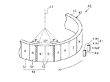
- FIG. 2 is a diagram illustrating the configuration of the rotation angle sensor.
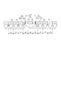
- FIG. 3 is a view showing a part of the magnetic ring developed in the circumferential direction
- FIG. 4 is a diagram showing a rotational position at which the magnetic flux reaches the maximum value in the magnetic ring
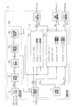
- FIG. 5 is a block diagram of processing performed by the ECU.
- FIG. 6 is a time chart showing signal processing of the pulse output unit
- FIG. 7 is a diagram illustrating an example of a rotational position where the rotational acceleration is maximized.
- FIG. 1 is an overall configuration diagram of an engine system.
- FIG. 2 is a diagram illustrating the configuration of the rotation angle sensor.
- FIG. 3 is a view showing a part of the magnetic ring developed in the circumferential direction
- FIG. 4 is a diagram showing a rotational position at which the magnetic flux reaches the maximum value in the magnetic ring
- FIG. 5 is a block diagram of processing performed by
- FIG. 8 is a diagram showing the combustion center of gravity and the ignition delay period
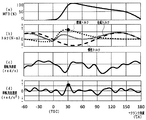
- FIG. 9 is a time chart showing changes in mass combustion ratio, torque, rotation speed, and rotation acceleration
- FIG. 10 is a diagram illustrating the detection accuracy of the rotational position where the rotational acceleration is maximum with respect to the detection resolution of the rotational angle sensor.
- the engine system includes a spark ignition type engine 10.
- an engine 10 having a plurality of cylinders is used.
- the intake passage 20 of the engine 10 is provided with an air flow meter 21 for detecting the amount of air taken in and a throttle valve 22.
- the opening degree of the throttle valve 22 is adjusted by an actuator such as a DC motor.
- a combustion chamber 10a of each cylinder of the engine 10 is connected to the downstream side of the throttle valve 22 in the intake passage 20 via a surge tank 23.
- the combustion chamber 10 a is partitioned by the cylinder block of the engine 10 and the piston 11.
- the engine 10 is provided with a fuel injection valve 12 having a tip projecting into the combustion chamber 10a.
- the fuel injection valve 12 directly injects and supplies fuel into the combustion chamber 10a by being energized.
- the engine 10 is provided with a spark plug 13.
- the spark plug 13 generates a discharge spark between the center electrode and the ground electrode. By this discharge spark, the air-fuel mixture containing fuel and air is ignited in the combustion chamber 10a.
- FIG. 1 only one cylinder is shown.
- the intake port and exhaust port of each cylinder of the engine 10 are opened and closed by an intake valve 24 and an exhaust valve 25.
- intake and EGR gas which will be described later, are introduced into the combustion chamber 10 a by opening the intake valve 24.
- fuel is injected into the combustion chamber 10a from the fuel injection valve 12 with intake air or the like being introduced and a discharge spark is generated in the spark plug 13, energy is generated by combustion of the air-fuel mixture. This energy is extracted as rotational energy of the crankshaft 14 of the engine 10 via the piston 11.
- the gas used for combustion is discharged as exhaust into the exhaust passage 26 when the exhaust valve 25 is opened.
- a part of the exhaust discharged to the exhaust passage 26 is returned to the intake passage 20 via the EGR passage 27.
- the exhaust passage 26 is connected to the surge tank 23 via the EGR passage 27.
- An EGR valve 28 is provided in the EGR passage 27.
- the opening degree of the EGR valve 28 is adjusted by an actuator such as a DC motor.
- a part of the exhaust discharged to the exhaust passage 26 is cooled by an EGR cooler (not shown) and then supplied to the surge tank 23 as EGR gas.
- the EGR passage 27 and the EGR valve 28 constitute an external EGR device.
- an air-fuel ratio sensor 29 for detecting the air-fuel ratio of the air-fuel mixture with exhaust as a detection target is provided downstream of the connection portion with the EGR passage 27.
- a catalyst 30 such as a three-way catalyst for purifying CO, HC, NOx and the like in the exhaust is provided downstream of the air-fuel ratio sensor 29 in the exhaust passage 26.
- the ECU 31 which is an electronic control device that controls the engine system, is configured mainly by a microcomputer including a well-known CPU, ROM, RAM, and the like.
- the ECU 31 receives detection signals from the air flow meter 21, the air-fuel ratio sensor 29, and the water temperature sensor 32 that detects the coolant temperature of the engine 10.
- the ECU 31 further receives an output signal from a magnetic detection unit 41 that constitutes a rotation angle sensor 40 for detecting the rotational position of the crankshaft 14.
- the rotation angle sensor 40 includes a magnetic detection unit 41 and a magnetic ring 42.
- the magnetic ring 42 has an annular ring portion 43 and a magnetic pole portion 50.
- the ring portion 43 is provided on the crankshaft 14 so as to rotate integrally with the crankshaft 14.
- the ring portion 43 is provided on the crankshaft 14 so that the rotation center axis L1 thereof coincides with the rotation center axis of the crankshaft 14.
- the crankshaft 14 rotates once
- the ring portion 43 also rotates once.
- a magnetic pole part 50 is formed on the outer peripheral surface of the ring part 43.
- the magnetic pole part 50 has a plurality of S pole parts 51 and the same number of N pole parts 52 as the S pole parts 51.
- the number of each of the S pole part 51 and the N pole part 52 is 29.
- the S pole portion 51 corresponds to the first magnetic portion
- the N pole portion 52 corresponds to the second magnetic portion.
- the S pole part 51 and the N pole part 52 are alternately arranged in the circumferential direction of the ring part 43 so as to form an annular shape.
- the width in the circumferential direction of the S pole portion 51 and the width in the circumferential direction of the N pole portion 52 are set to be equal.
- the circumferential width of the S pole part 51 and the N pole part 52 is set to 6 °.
- the magnetic pole part 50 has one weakly magnetized part 53 having a lower magnetic force than each of the S pole part 51 and the N pole part 52.
- the weakly magnetized portion 53 is disposed between one of the plurality of S pole portions 51 and one of the plurality of N pole portions 52.
- the weakly magnetized portion 53 is provided to determine a rotational position that serves as a reference for the crankshaft 14. By determining the reference rotational position, the rotational position (CA) of the crankshaft 14 can be grasped.
- the width in the circumferential direction of the weakly magnetized portion 53 is set to be longer than the width in the circumferential direction of the S-pole portion 51 and the N-pole portion 52, and specifically set to 12 °. .
- the S pole portion 51 adjacent to the first side surface 53a in the circumferential direction of the weakly magnetized portion 53 is referred to as a right magnetic portion 51.
- the magnetic force of the right magnetic part 51 is lower than the magnetic force of the other S pole parts 51.
- the N pole portion 52 adjacent to the second side surface 53 b in the circumferential direction of the weakly magnetized portion 53 is referred to as a left magnetic portion 52.
- the magnetic force of the left magnetic part 52 is lower than the magnetic force of the other N pole parts 52.
- the weakly magnetized portion 53 has a right magnetized portion 54 adjacent to the right magnetic portion 51 and a left magnetized portion 55 adjacent to the left magnetic portion 52.
- the right magnetized portion 54 is magnetized to the S pole, and the left magnetized portion 55 is magnetized to the N pole.
- the right magnetized portion 54 has a magnetic force lower than that of the right magnetic portion 51, and the left magnetized portion 55 has a magnetic force lower than that of the left magnetic portion 52.
- Each of the right magnetized portion 54 and the left magnetized portion 55 is set to have the same width in the circumferential direction, specifically, set to 6 °.
- the right magnetic part 51 has a right different pole part 51a adjacent to the right magnetized part 54 and a right main part 51b adjacent to the right different pole part 51a in the circumferential direction.
- the right different pole portion 51a is magnetized to the N pole, and the right main body portion 51b is magnetized to the S pole. 2 to 4, the right different pole portion 51a is indicated by hatching.
- the magnetic force per unit area of each of the right different pole part 51a and the right main body part 51b is equal.
- the width in the circumferential direction of the right different pole portion 51a is set to be smaller than the width in the circumferential direction of the right main body portion 51b.
- the magnetic force of the right main body 51b is larger than the magnetic force of the right different pole portion 51a, and the magnetic force of the right magnetic portion 51 is generally the S pole.
- the magnetic force of the right magnetic part 51 is larger than the magnetic force of the right magnetized part 54 among the plurality of S pole parts 51 and smaller than the magnetic force of the other S pole parts 51. Thereby, it can suppress that the magnetic field of the same polarity is formed by the right magnetic part 51 and the right magnetized part 54.
- the position where the normal direction component of the outer peripheral surface of the right magnetic part 51 becomes the maximum in the magnetic field formed by the right magnetic part 51 is the circumferential direction of the right magnetic part 51. It is possible to suppress the deviation from the center at.
- the left magnetic part 52 has a left different pole part 52a adjacent to the left magnetized part 55 and a left main part 52b adjacent to the left different pole part 52a in the circumferential direction.
- the left different pole portion 52a is magnetized to the S pole, and the left main body portion 52b is magnetized to the N pole. 2 to 4, the left different pole portion 52a is indicated by hatching.
- the magnetic forces per unit area of the left different pole portion 52a and the left main body portion 52b are equal.
- the width in the circumferential direction of the left different pole portion 52a is set to be smaller than the width in the circumferential direction of the left main body portion 52b.
- the magnetic force of the left main body portion 52b is larger than the magnetic force of the left different pole portion 52a, and the magnetic force of the left magnetic portion 52 is generally N-pole.
- the magnetic force of the left magnetic part 52 is larger than the magnetic force of the left magnetized part 55 among the plurality of N pole parts 52 and smaller than the magnetic force of the other N pole parts 52. Thereby, it is possible to suppress the magnetic field having the same polarity from being formed by the left magnetic part 52 and the left magnetized part 55.
- the position where the normal direction component of the outer peripheral surface of the left magnetic portion 52 becomes the maximum in the magnetic field formed by the left magnetic portion 52 is the circumferential direction of the left magnetic portion 52. It is possible to suppress the deviation from the center at.
- the magnetic detection unit 41 includes a first conversion unit 41a and a second conversion unit 41b.
- the 1st, 2nd conversion parts 41a and 41b are comprised by the Hall element.
- the first and second conversion parts 41 a and 41 b are arranged to face the magnetic pole part 50 via a predetermined air gap in the radial direction of the ring part 43.
- the first and second converters 41 a and 41 b detect the magnetic flux along the radial direction of the ring portion 43, that is, the magnetic flux along the normal direction of the formation surface of the magnetic pole portion 50. Magnetic flux along the circumferential direction and the central axis L1 direction is not detected.
- the magnetic ring 42 When the crankshaft 14 rotates, the magnetic ring 42 also rotates together. Thereby, the magnetic flux which penetrates the 1st, 2nd conversion parts 41a and 41b changes periodically. Specifically, the fluctuation cycle of the normal magnetic flux, which is a magnetic flux along the radial direction passing through the first and second converters 41a and 41b, is 12 °.
- the 1st, 2nd conversion parts 41a and 41b are arrange
- the normal magnetic flux does not change periodically when the first and second conversion parts 41 a and 41 b are opposed to the weakly magnetized part 53. Thereby, the reference
- 1st conversion part 41a converts the magnetic flux which changes periodically into an electric signal, and outputs it to ECU31 as the 1st rotation signal Sg1.
- the 2nd conversion part 41b converts the magnetic flux which changes periodically into an electric signal, and outputs it to ECU31 as the 2nd rotation signal Sg2.
- the first rotation signal Sg1 and the second rotation signal Sg2 have the same period.
- the first rotation signal Sg1 and the second rotation signal Sg2 have the same amplitude, and each has a sinusoidal waveform.
- ECU31 performs the combustion control process of the engine 10 based on the detection value of the various sensors mentioned above. This process includes a fuel injection control process for the fuel injection valve 12, an ignition control process for the spark plug 13, and a drive control process for the EGR valve 28. The ECU 31 further performs processing for estimating the combustion state in the combustion chamber 10a of each cylinder used for combustion control. Hereinafter, these processes will be described with reference to FIG.
- the ECU31 is provided with the state estimation part 60 which estimates the combustion state in the combustion chamber 10a.
- the pulse output unit 61 outputs the pulse signal SgP based on the first rotation signal Sg1 and the second rotation signal Sg2.
- the processing of the pulse output unit 61 is performed using the technique described in Japanese Patent Application Laid-Open No. 2015-38465.
- FIG. 6A and 6B show transitions of the first and second rotation signals Sg1 and Sg2 input to the pulse output unit 61.
- FIG. 6C is output from the pulse output unit 61. The transition of the pulse signal SgP is shown.
- FIG. 6A and 6B show transitions of the first and second rotation signals Sg1 and Sg2 input to the pulse output unit 61.
- a period in which the first rotation signal Sg1 goes from the intermediate value between the peak value and the bottom value to the peak value, and the second rotation signal Sg2 goes from the peak value to the intermediate value is a first period T1
- the first rotation A period in which the signal Sg1 goes from the peak value to the intermediate value and the second rotation signal Sg2 goes from the intermediate value to the bottom value is defined as a second period T2.
- a period in which the first rotation signal Sg1 goes from the intermediate value to the bottom value, the second rotation signal Sg2 goes from the bottom value to the intermediate value is a third period T3, and the first rotation signal Sg1 goes from the bottom value to the intermediate value.
- a period during which the second rotation signal Sg2 goes from the intermediate value to the peak value is defined as a fourth period T4.
- the first detection threshold Vthd1 is set to the first threshold Vth1
- the second detection threshold Vthd2 is set to the second threshold Vth2 ( ⁇ Vth1).
- the pulse signal SgP is output.
- the first detection threshold Vthd1 is switched from the first threshold Vth1 to the second threshold Vth2, and the second detection threshold Vthd2 is changed from the second threshold Vth2 to the first.
- the threshold value is switched to Vth1.
- the pulse signal SgP is output.
- the second detection threshold Vthd2 is switched from the first threshold Vth1 to the third threshold Vth3 (> Vth1), and the first detection threshold Vthd1 is set to the second threshold.
- the threshold value is switched from Vth2 to the first threshold value Vth1.
- the pulse signal SgP is output.
- the first detection threshold value Vthd1 is switched from the first threshold value Vth1 to the third threshold value Vth3
- the second detection threshold value Vthd2 is changed from the third threshold value Vth3 to the first threshold value.
- the threshold value is switched to Vth1.
- the pulse signal SgP is output.
- the second detection threshold Vthd2 is switched from the first threshold Vth1 to the second threshold Vth2, and the first detection threshold Vthd1 is changed from the third threshold Vth3 to the first threshold.
- the threshold value is switched to Vth1. Thereafter, the above-described processing in the first period T1 is performed.
- the pulse output unit 61 generates the pulse signal SgP at the timing when the first rotation signal Sg1 crosses the first detection threshold Vthd1 and at the timing when the second rotation signal Sg2 crosses the second detection threshold Vthd2. Is output. Therefore, in the present embodiment, the pulse signal SgP is output every time the crankshaft 14 rotates 3 °. For this reason, the detection resolution of the rotation position of the rotation angle sensor 40 is 3 °.
- the angular velocity calculation unit 62 calculates the rotational angular velocity ⁇ r of the crankshaft 14 based on the pulse signal SgP output from the pulse output unit 61. Specifically, the angular velocity calculation unit 62 calculates a rotation angular velocity ⁇ r by calculating a time interval at which the pulse signal SgP is output and multiplying the inverse of the calculated time interval by a predetermined coefficient.
- the filter processing unit 63 receives the rotational angular velocity ⁇ r calculated by the angular velocity calculating unit 62 as an input, extracts the fluctuation component of the combustion torque of the engine 10 from the rotational angular velocity ⁇ r, and outputs it.
- the filter processing unit 63 is configured by a band pass filter.
- the lower limit cutoff frequency FL that defines the lower limit of the pass band of the bandpass filter is set so that the fluctuation component due to the inertia torque of the engine 10 can be removed from the rotational angular velocity ⁇ r.
- the lower limit cutoff frequency FL may be variably set according to the rotational angular velocity of the crankshaft 14.
- the rotational angular velocity used when setting the lower limit cutoff frequency FL may be a value obtained by, for example, the rotational angular velocity ⁇ r calculated by the angular velocity calculator 62.
- the upper cutoff frequency FH that defines the upper limit of the passband of the bandpass filter is set so that high frequency noise included in the rotational angular velocity ⁇ r can be removed.
- the high frequency noise includes, for example, noise generated at the start of driving an on-vehicle auxiliary machine such as an air conditioner compressor.
- the filter processing unit 63 corresponds to a waveform acquisition unit.
- the angular acceleration calculation unit 64 calculates the rotational angular acceleration acc of the crankshaft 14 as a time differential value of the rotational angular velocity ⁇ f calculated by the filter processing unit 63.
- the maximum position calculating unit 65 is a rotational position where the rotational angular acceleration acc becomes the maximum value in the first half of the expansion stroke of the engine 10, as shown in FIG. A certain maximum rotational position tmax is calculated.
- the ECU 31 includes a combustion control unit 70.
- the target value setting unit 71 sets the target ignition timing tst of the spark plug 13, the target injection amount Qt of the fuel injection valve 12, and the target EGR rate Et based on the operating state of the engine 10.
- the EGR rate is defined as the ratio of the amount of EGR gas to the total amount of intake air and EGR gas introduced into the combustion chamber 10a.
- the target ignition timing tst is set to an optimal ignition timing (MBT) determined for each operating state of the engine 10.
- MBT optimal ignition timing
- the detection value of the air-fuel ratio sensor 29 is also used for setting the target injection amount Qt.
- the target state setting unit 72 is based on the rotational angular velocity ⁇ f calculated by the filter processing unit 63, the intake air amount G detected by the air flow meter 21, and the cooling water temperature THW detected by the water temperature sensor 32.
- a target combustion gravity center tgt which is a value and a target ignition delay period tdt which is a target value of an ignition delay period are set.
- the combustion center of gravity is defined as the rotational position t3 of the crankshaft 14 with respect to the center position (50%) of the mass combustion ratio (MFB) after the start of combustion, as shown in FIG.
- the ignition delay period is defined as a period from the rotational position t1 at which the ignition spark of the spark plug 13 is generated to the rotational position t2 at which the fuel injected from the fuel injection valve 12 is ignited.
- the rotational position t2 is defined as the rotational position at which the mass combustion ratio reaches 10% with respect to the maximum value of the mass combustion ratio 100%.
- the first control unit 73 sets the target ignition timing tst based on the maximum rotational position tmax calculated by the maximum position calculation unit 65 so as to control the actual combustion center of gravity to the target combustion center of gravity tgt. Correct.
- the reason why the maximum rotation position tmax is used for correcting the target ignition timing tst is that there is a correlation between the maximum rotation position tmax and the actual combustion center of gravity. Specifically, when the combustion center of gravity is advanced, the maximum rotational position tmax is also advanced, and when the combustion center of gravity is retarded, the maximum rotational position tmax is also retarded.
- the maximum rotation position tmax corresponds to the combustion torque reflecting the heat generation behavior from the start to the end of combustion, it has a high correlation with the combustion center of gravity.
- FIG. 10 shows an example of changes in the mass combustion ratio, the combustion torque, the inertia torque, the combined torque obtained by synthesizing these torques, the rotational angular velocity of the crankshaft 14, and the rotational angular acceleration.
- the rotation position near 30 degrees from the compression top dead center is the maximum rotation position tmax.
- the rotational position where the combustion torque is maximum and the maximum rotational position tmax coincide.
- the first controller 73 first calculates the gravity center position difference ⁇ tg by subtracting the maximum rotational position tmax from the target combustion gravity center tgt.
- the first control unit 73 corrects the target ignition timing tst to be retarded so as to delay the ignition timing.
- the maximum rotational position tmax appears on the retard side of the combustion center of gravity, which is the rotational position where the mass combustion ratio is 50%. For this reason, the first predetermined value ⁇ is set to a negative value.
- the first control unit 73 determines that the calculated center-of-gravity position difference ⁇ tg is smaller than the first predetermined value ⁇ , the first control unit 73 corrects the target ignition timing tst to advance to advance the ignition timing.
- the first predetermined value ⁇ may be set to zero.
- the target ignition timing tst corrected by the first control unit 73 is input to the ignition drive circuit 80.
- the ignition drive circuit 80 outputs an ignition signal Sgigt to the ignition plug 13 so that an ignition spark is generated in the ignition plug 13 at the corrected target ignition timing tst.
- the second control unit 74 sets the target injection amount Qt and the target EGR rate Et based on the maximum rotation position tmax calculated by the maximum position calculation unit 65 in order to control the actual ignition delay period to the target ignition delay period tdt. to correct.
- the reason why the maximum rotational position tmax is used for correcting the target injection amount Qt and the target EGR rate Et is that there is a correlation between the maximum rotational position tmax and the ignition delay time. Specifically, when the ignition delay time is shortened, the maximum rotation position tmax is advanced, and when the ignition delay time is increased, the maximum rotation position tmax is retarded.
- the second control unit 74 calculates the actual delay period tdr by subtracting the target ignition timing tst from the maximum rotation position tmax, and subtracts the actual delay period tdr from the target ignition delay period tdt, thereby calculating the ignition delay difference ⁇ td. Is calculated. If the second control unit 74 determines that the ignition delay difference ⁇ td is greater than the second predetermined value ⁇ ( ⁇ 0), the second control unit 74 corrects the target injection amount Qt to decrease the actual injection delay period, and Then, the target EGR rate Et is corrected to be increased. Since the maximum rotation position tmax is located on the retard side with respect to the end timing of the ignition delay time, the second predetermined value ⁇ is set to a negative value.
- the second control unit 74 corrects the target injection amount Qt to increase the target injection amount Qt in order to shorten the actual ignition delay period, and The EGR rate Et is corrected to decrease.
- the target injection amount Qt corrected by the second control unit 74 is input to the injection drive circuit 81.
- the injection drive circuit 81 outputs an injection command signal Sginj to the fuel injection valve 12 so that the fuel injection amount from the fuel injection valve 12 becomes the corrected target injection amount Qt.
- the target EGR rate Et corrected by the second control unit 74 is input to the EGR drive circuit 82.
- the EGR drive circuit 82 outputs a drive command signal Sgegr to the actuator that drives the EGR valve 28 so that the actual EGR rate becomes the target EGR rate Et.
- the detection resolution of the rotation angle position of the rotation angle sensor 40 is set to 3 ° in order to accurately detect the maximum rotation position tmax correlated with the combustion center of gravity.
- FIG. 10 shows the detection result of the maximum rotational position tmax with respect to the actual combustion center of gravity when the detection resolution is set to 1 °, 3 °, 4 °, and 10 °. From experiments and the like, it was confirmed that the actual combustion gravity center and the maximum rotation position tmax are in a proportional relationship at 1 ° and 3 °. When the detection resolution is 4 ° or 10 °, the proportional relationship between the maximum rotational position tmax and the combustion center of gravity is lost. For this reason, the detection resolution needs to be 3 ° or less.
- the signal of the fluctuation component of the combustion torque was extracted from the rotational angular velocity ⁇ r of the crankshaft 14 by the filter processing unit 63, and the rotational angular acceleration acc of the crankshaft 14 was calculated based on the extracted signal ⁇ f. Then, for each cylinder, in the first half of the expansion stroke, the rotation angle position where the calculated rotation angular acceleration acc is the maximum value is calculated as the maximum rotation position tmax. Since the maximum rotation position tmax is highly correlated with the combustion center of gravity and the ignition delay period, the maximum rotation position tmax accurately estimates the deviation between the actual combustion center of gravity and the ignition delay period and its target value. Can do.
- the rotation angle position at which the rotation angular acceleration acc becomes the maximum value is less likely to vary due to various factors that affect the combustion state as compared with the absolute value of the rotation angular acceleration acc. For this reason, according to the maximum rotation position tmax, it is possible to improve the estimation accuracy of the deviation between each of the combustion center of gravity and the ignition delay period and its target value.
- the maximum rotational position tmax reflects the heat generation behavior during the combustion period from the start to the end of combustion, and has a high correlation with the combustion state. For this reason, according to the maximum rotation position tmax, it is possible to improve the estimation accuracy of the deviation between each of the combustion center of gravity and the ignition delay period and its target value.
- the combustion state in the combustion chamber 10a was estimated. Therefore, an in-cylinder pressure sensor that detects the pressure in the combustion chamber 10a, an ion current sensor that detects an ionic current generated according to the flame state in the combustion chamber 10a, and the like are not provided for each cylinder of the engine 10. The combustion state of each cylinder can be accurately estimated.
- the target ignition timing tst, the target injection amount Qt, and the target EGR rate Et were corrected based on the maximum rotation position tmax. For this reason, the combustion control of the engine 10 can be performed appropriately, and the combustion state can be maintained satisfactorily.
- the maximum rotational position tmax which is the rotational position where the rotational angular acceleration acc is the maximum value, is used as the parameter for estimating the combustion state, but this is not restrictive.
- a rotational position where the rotational angular acceleration acc appearing in the first half of the expansion stroke becomes an extreme value (maximum value or minimum value) may be used.
- the parameters for estimating the combustion state are not limited to the rotational position, and for example, the difference between the maximum value and the minimum value of the rotational angular acceleration acc appearing in the first half of the expansion stroke, or the rotational angular acceleration acc appearing in the first half of the expansion stroke. It may be a time interval between extreme values, a fluctuation frequency of the rotational angular acceleration acc in the first half of the expansion stroke, or a rising speed of the rotational angular acceleration acc when the rotational angular acceleration acc increases toward its maximum value.
- the ECU 31 permits estimation of the combustion state based on the maximum rotational position tmax when it is determined that the load of the engine 10 is higher than the predetermined load, and determines that the load of the engine 10 is equal to or less than the predetermined load. In this case, estimation of the combustion state based on the maximum rotational position tmax may be prohibited. This is because, when the load on the engine 10 is low, the combustion torque becomes small and the maximum value of the rotational angular acceleration acc becomes small, so that the detection accuracy of the maximum rotational position tmax may be lowered.
- the width in the circumferential direction of the weakly magnetized portion 53 may be set smaller than the width in the circumferential direction of the S pole portion 51 and the N pole portion 52.
- the respective circumferences of the S pole part 51 and the N pole part 52 may be set to a value other than 6 °, and the width in the circumferential direction of the weakly magnetized portion 53 may be set to a value other than 12 °.
- the width in the circumferential direction of each of the S pole portion 51 and the N pole portion 52 may be set to 3 °, and the width in the circumferential direction of the weakly magnetized portion 53 may be set to 6 °.
- the detection resolution of the rotation angle sensor 40 is 1.5 °.
- the magnetic pole portion may be formed not on the outer peripheral surface of the ring portion 43 but on the inner peripheral surface of the ring portion 43 or the end surface of the ring portion 43 in the direction of the central axis L1.
- a 1st, 2nd conversion part which comprises a magnetic detection part, it is comprised not only with a Hall element but with a magnetoresistive element from which resistance value changes according to the direction of the magnetic flux which permeate
- the engine 10 may be provided with a speed increaser whose input shaft is connected to the crankshaft 14 and a rotating body to which the output shaft of the speed increaser is connected.
- the rotational speed of the rotating body is higher than the rotational speed of the crankshaft 14. Therefore, when the engine system is provided with a rotation angle sensor that outputs a pulse signal every time the rotating body rotates by an equal angle, the number of pulses included in the pulse signal can be increased, and the rotation position of the crankshaft 14 can be detected.
- the resolution can be increased.
- an electromagnetic pickup type sensor may be used as the rotation angle sensor.
- the filter processing unit 63 may be configured by a low-pass filter.
- At least one of the target ignition timing tst, the target injection amount Qt, and the target EGR rate Et may be a correction target.
- the parameters to be corrected are not limited to the target ignition timing tst, the target injection amount Qt, and the target EGR rate Et, but may be the target injection timing of the fuel injection valve 12, for example.
- the internal combustion engine is not limited to a direct injection type in which fuel is directly injected and supplied into the combustion chamber, but may be a port injection type in which fuel is injected and supplied to the intake port.
- the internal combustion engine is not limited to a spark ignition type, and may be a compression ignition type such as a diesel engine.
- whether or not the combustion state in the combustion chamber is abnormal may be estimated based on the rotational angular acceleration acc.
Landscapes
- Engineering & Computer Science (AREA)
- General Engineering & Computer Science (AREA)
- Chemical & Material Sciences (AREA)
- Combustion & Propulsion (AREA)
- Mechanical Engineering (AREA)
- General Physics & Mathematics (AREA)
- Physics & Mathematics (AREA)
- Signal Processing (AREA)
- Combined Controls Of Internal Combustion Engines (AREA)
- Electrical Control Of Air Or Fuel Supplied To Internal-Combustion Engine (AREA)
- Measurement Of Length, Angles, Or The Like Using Electric Or Magnetic Means (AREA)
- Electrical Control Of Ignition Timing (AREA)
- Output Control And Ontrol Of Special Type Engine (AREA)
Abstract
制御装置は、内燃機関の出力軸の所定角度ごとに回転信号を出力する回転検出器の出力信号に基づいて、出力軸の回転速度を算出する。制御装置は、算出した回転速度を入力として、ローパスフィルタ処理により、出力軸の回転位置に対する回転速度の変化を示す波形データを取得する。制御装置は、取得した波形データに基づいて、出力軸の回転位置に対する回転加速度を算出し、算出した回転加速度に基づいて、燃焼室内の燃焼状態を推定する。
Description
本出願は、2016年2月24日に出願された日本出願番号2016-033532号に基づくもので、ここにその記載内容を援用する。
本開示は、内燃機関の制御装置に関する。
従来、下記特許文献1に見られるように、内燃機関のクランク軸の回転角度位置を検出するクランク角センサの出力信号に基づいて、内燃機関の燃焼制御を行う制御装置が知られている。詳しくは、この制御装置は、クランク角センサの出力信号に基づいてクランク軸の回転速度の変動値を算出し、算出した変動値が安定度目標値に近づくように空燃比制御を行う。この制御装置において回転速度の変動値が用いられているのは、回転速度の変動値が内燃機関の燃焼室内の燃焼状態と相関があるためである。
クランク軸の回転速度の変動値は、燃焼室に供給される吸入空気量のばらつき等、燃焼室内の燃焼状態と相関の低い要因の影響を受けやすい。このため、回転速度の変動値では、燃焼室内の燃焼状態を精度よく推定することはできない。
本開示は、燃焼室内の燃焼状態の推定精度を向上できる内燃機関の制御装置を提供することを主たる目的とする。
以下、上記課題を解決するための手段、及びその作用効果について記載する。
本開示は、内燃機関の出力軸の所定角度ごとに回転信号を出力する回転検出器を備えるシステムに適用され、前記回転検出器の出力信号に基づいて、前記出力軸の回転速度を算出する速度算出部と、前記速度算出部により算出した前記回転速度を入力として、ローパスフィルタ処理により、前記出力軸の回転位置に対する前記回転速度の変化を示す波形データを取得する波形取得部と、前記波形データに基づいて、前記出力軸の回転位置に対する回転加速度を算出する加速度算出部と、前記加速度算出部により算出した前記回転加速度に基づいて、前記内燃機関の燃焼室内の燃焼状態を推定する推定部と、を備える。
内燃機関が燃焼により回転駆動される際には、出力軸に、各気筒での燃焼により生じる燃焼トルクが付与されるとともに、各気筒において圧縮行程や膨張行程での燃焼室内の容積変化により生じる慣性トルクが付与される。また、回転検出器の出力信号によれば、燃焼トルクと慣性トルクとを合算した合成トルクに対応するものとして回転速度が検出される。この場合、内燃機関の燃焼状態を高精度に把握するには、出力軸に付与される合成トルクのうち燃焼トルクだけを抽出することが望ましい。
この点、上記開示によれば、出力軸の回転位置に対する回転速度の変化を示す波形データに基づいて、出力軸の回転位置に対する回転加速度が算出される。回転加速度は、燃焼で発生した燃焼トルクにより上昇した後、下降に転じ、内燃機関の熱発生挙動を反映したものとなる。このため回転加速度は、内燃機関の燃焼状態を適正に示す指標となる。したがって、加速度算出部により算出された回転加速度に基づいて、燃焼室内の燃焼状態を推定することにより、燃焼状態の推定精度を向上させることができる。
本開示についての上記目的およびその他の目的、特徴や利点は、添付の図面を参照しながら下記の詳細な記述により、より明確になる。その図面は、
図1は、エンジンシステムの全体構成図であり、
図2は、回転角センサの構成を示す図であり、
図3は、周方向に展開した磁気リングの一部を示す図であり、
図4は、磁気リングにおいて磁束が最大値となる回転位置を示す図であり、
図5は、ECUが行う処理のブロック図であり、
図6は、パルス出力部の信号処理を示すタイムチャートであり、
図7は、回転加速度が最大となる回転位置の一例を示す図であり、
図8は、燃焼重心及び着火遅れ期間を示す図であり、
図9は、質量燃焼割合、トルク、回転速度及び回転加速度の推移を示すタイムチャートであり、
図10は、回転角センサの検出分解能に対する回転加速度が最大となる回転位置の検出精度を示す図である。
以下、本開示に係る制御装置を具体化した一実施形態について、図面を参照しつつ説明する。
図1に示すように、エンジンシステムは、火花点火式のエンジン10を備えている。本実施形態では、エンジン10として、複数の気筒を有するものを用いている。エンジン10の吸気通路20には、吸入される空気量を検出するエアフローメータ21と、スロットルバルブ22とが設けられている。スロットルバルブ22の開度は、DCモータ等のアクチュエータにより調節される。
吸気通路20においてスロットルバルブ22の下流側には、サージタンク23を介してエンジン10の各気筒の燃焼室10aが接続されている。燃焼室10aは、エンジン10のシリンダブロック及びピストン11にて区画されている。エンジン10には、燃焼室10a内に先端部が突出した燃料噴射弁12が設けられている。燃料噴射弁12は、通電操作されることにより、燃焼室10a内に燃料を直接噴射供給する。エンジン10には、点火プラグ13が設けられている。点火プラグ13は、中心電極及び接地電極の間に放電火花を発生させる。この放電火花により、燃焼室10a内において燃料及び空気を含む混合気が着火される。なお図1では、1つの気筒のみを示している。
エンジン10の各気筒の吸気ポート,排気ポートは、吸気バルブ24,排気バルブ25により開閉される。ここでは、吸気バルブ24の開弁によって吸気や、後述するEGRガスが燃焼室10aに導入される。吸気等が導入された状態で燃料噴射弁12から燃焼室10a内に燃料が噴射され、点火プラグ13に放電火花が発生すると、混合気の燃焼によってエネルギが発生する。このエネルギは、ピストン11を介して、エンジン10のクランク軸14の回転エネルギとして取り出される。燃焼に供されたガスは、排気バルブ25の開弁によって、排気通路26に排気として排出される。
排気通路26に排出された排気の一部は、EGR通路27を介して吸気通路20に還流される。詳しくは、排気通路26は、EGR通路27を介してサージタンク23に接続されている。EGR通路27には、EGRバルブ28が設けられている。EGRバルブ28の開度は、DCモータ等のアクチュエータにより調節される。EGRバルブ28の開度に応じて、排気通路26に排出された排気の一部が、図示しないEGRクーラによって冷却された後にEGRガスとしてサージタンク23に供給される。なお本実施形態において、EGR通路27及びEGRバルブ28が外部EGR装置を構成する。
排気通路26においてEGR通路27との接続部よりも下流側には、排気を検出対象として混合気の空燃比を検出する空燃比センサ29が設けられている。排気通路26において空燃比センサ29の下流側には、排気中のCO,HC,NOx等を浄化するための三元触媒等の触媒30が設けられている。
エンジンシステムを制御対象とする電子制御装置であるECU31は、周知のCPU、ROM、RAM等を含むマイクロコンピュータを主体として構成されている。ECU31には、エアフローメータ21、空燃比センサ29、及びエンジン10の冷却水温を検出する水温センサ32の検出信号が入力される。ECU31には、さらに、クランク軸14の回転位置を検出するための回転角センサ40を構成する磁気検出部41の出力信号が入力される。
続いて、図2~図4を用いて、回転角センサ40について説明する。
図示されるように、回転角センサ40は、磁気検出部41と、磁気リング42とを備えている。磁気リング42は、円環状のリング部43と、磁極部50とを有している。リング部43は、クランク軸14と一体となって回転するようにクランク軸14に設けられている。詳しくは、リング部43は、その回転中心軸線L1がクランク軸14の回転中心軸線と一致するようにクランク軸14に設けられている。クランク軸14が1回転すると、リング部43も1回転する。
リング部43の外周面には、磁極部50が形成されている。磁極部50は、複数のS極部51と、S極部51と同数のN極部52とを有している。本実施形態において、S極部51及びN極部52のそれぞれの数は29個である。なお本実施形態において、S極部51が第1磁性部に相当し、N極部52が第2磁性部に相当する。
S極部51とN極部52とは、リング部43の周方向において、円環状をなすように交互に並んで配置されている。本実施形態において、S極部51の周方向における幅と、N極部52の周方向における幅とが等しく設定されている。具体的には、S極部51及びN極部52の周方向における幅が6°に設定されている。
磁極部50は、S極部51及びN極部52のそれぞれよりも磁力の低い1つの弱着磁部53を有している。弱着磁部53は、複数のS極部51のうち1つと、複数のN極部52のうち1つとの間に配置されている。弱着磁部53は、クランク軸14の基準となる回転位置を定めるために設けられている。基準となる回転位置が定められることにより、クランク軸14の回転位置(CA)を把握することができる。本実施形態において、弱着磁部53の周方向における幅は、S極部51及びN極部52の周方向における幅よりも長く設定されており、具体的には12°に設定されている。
複数のS極部51のうち、弱着磁部53の周方向における第1側面53aと隣接するS極部51を右方磁性部51と称すこととする。複数のS極部51のうち、右方磁性部51の磁力は、他のS極部51の磁力よりも低い。また、複数のN極部52のうち、弱着磁部53の周方向における第2側面53bと隣接するN極部52を左方磁性部52と称すこととする。複数のN極部52のうち、左方磁性部52の磁力は、他のN極部52の磁力よりも低い。
弱着磁部53は、右方磁性部51と隣接する右着磁部54と、左方磁性部52と隣接する左着磁部55とを有している。右着磁部54はS極に着磁され、左着磁部55はN極に着磁されている。右着磁部54は、その磁力が右方磁性部51の磁力よりも低く、左着磁部55は、その磁力が左方磁性部52の磁力よりも低くなっている。右着磁部54及び左着磁部55のそれぞれは、周方向における幅が互いに等しく設定されており、具体的には6°に設定されている。
右方磁性部51は、周方向において、右着磁部54と隣接する右異極部51a、及び右異極部51aと隣接する右本体部51bを有している。右異極部51aはN極に着磁され、右本体部51bはS極に着磁されている。図2~図4には、右異極部51aをハッチングにて示している。
右異極部51a及び右本体部51bのそれぞれの単位面積あたりの磁力は等しい。また、右異極部51aの周方向における幅は、右本体部51bの周方向における幅よりも小さく設定されている。このため、右本体部51bの磁力は、右異極部51aの磁力よりも大きく、右方磁性部51の磁力は総じてS極となっている。そして右方磁性部51の磁力は、複数のS極部51のうち、右着磁部54の磁力よりも大きく、他のS極部51の磁力よりも小さくなっている。これにより、右方磁性部51と右着磁部54とによって同一極性の磁界が形成されることを抑制できる。その結果、図4に示すように、右方磁性部51により形成される磁界のうち右方磁性部51の外周面の法線方向成分が最大となる位置が、右方磁性部51の周方向における中心からずれることを抑制できる。
左方磁性部52は、周方向において、左着磁部55と隣接する左異極部52a、及び左異極部52aと隣接する左本体部52bを有している。左異極部52aはS極に着磁され、左本体部52bはN極に着磁されている。図2~図4には、左異極部52aをハッチングにて示している。
左異極部52a及び左本体部52bのそれぞれの単位面積あたりの磁力は等しい。また、左異極部52aの周方向における幅は、左本体部52bの周方向における幅よりも小さく設定されている。このため、左本体部52bの磁力は、左異極部52aの磁力よりも大きく、左方磁性部52の磁力は総じてN極となっている。そして左方磁性部52の磁力は、複数のN極部52のうち、左着磁部55の磁力よりも大きく、他のN極部52の磁力よりも小さくなっている。これにより、左方磁性部52と左着磁部55とによって同一極性の磁界が形成されることを抑制できる。その結果、図4に示すように、左方磁性部52により形成される磁界のうち左方磁性部52の外周面の法線方向成分が最大となる位置が、左方磁性部52の周方向における中心からずれることを抑制できる。
磁気検出部41は、第1変換部41aと、第2変換部41bとを有している。本実施形態において、第1,第2変換部41a,41bは、ホール素子により構成されている。第1,第2変換部41a,41bは、リング部43の径方向において磁極部50と所定のエアギャップを介して対向配置されている。本実施形態において、第1,第2変換部41a,41bは、リング部43の径方向に沿う磁束、すなわち磁極部50の形成面の法線方向に沿う磁束を検出するものの、リング部43の周方向及び中心軸線L1方向に沿う磁束は検出しない。
クランク軸14が回転すると、磁気リング42も一体となって回転する。これにより、第1,第2変換部41a,41bを貫く磁束が周期的に変化する。詳しくは、第1,第2変換部41a,41bを貫く径方向に沿う磁束である法線磁束の変動周期は、12°となる。本実施形態では、第1変換部41aを貫く法線磁束と第2変換部41bを貫く法線磁束との位相が90°ずれるように第1,第2変換部41a,41bが配置されている。ただし、法線磁束は、第1,第2変換部41a,41bが弱着磁部53と対向している場合、周期的に変化しなくなる。これにより、クランク軸14の回転位置の基準を定めることができる。
第1変換部41aは、周期的に変化する磁束を電気信号に変換して第1回転信号Sg1としてECU31に出力する。第2変換部41bは、周期的に変化する磁束を電気信号に変換して第2回転信号Sg2としてECU31に出力する。本実施形態において、第1回転信号Sg1と第2回転信号Sg2とは互いに周期が等しい。また本実施形態では、第1回転信号Sg1と第2回転信号Sg2とは振幅が同一であり、それぞれ正弦波状の波形である。
ECU31は、上述した各種センサの検出値に基づいて、エンジン10の燃焼制御処理を行う。この処理には、燃料噴射弁12の燃料噴射制御処理、点火プラグ13の点火制御処理、及びEGRバルブ28の駆動制御処理が含まれる。ECU31は、さらに、燃焼制御に用いる各気筒の燃焼室10a内の燃焼状態を推定する処理を行う。以下、図5を用いて、これら処理について説明する。
ECU31は、燃焼室10a内の燃焼状態を推定する状態推定部60を備えている。状態推定部60において、パルス出力部61は、第1回転信号Sg1及び第2回転信号Sg2に基づいて、パルス信号SgPを出力する。本実施形態において、パルス出力部61の処理は、特開2015-38465号公報に記載された手法を用いて行われる。以下、図6を用いて、パルス出力部61の処理について説明する。ここで、図6(a),(b)はパルス出力部61に入力される第1,第2回転信号Sg1,Sg2の推移を示し、図6(c)はパルス出力部61から出力されるパルス信号SgPの推移を示す。なお図6では、第1回転信号Sg1がピーク値とボトム値との中間値からピーク値に向かい、第2回転信号Sg2がピーク値から中間値に向かう期間を第1期間T1とし、第1回転信号Sg1がピーク値から中間値に向かい、第2回転信号Sg2が中間値からボトム値に向かう期間を第2期間T2とする。また、第1回転信号Sg1が中間値からボトム値に向かい、第2回転信号Sg2がボトム値から中間値に向かう期間を第3期間T3とし、第1回転信号Sg1がボトム値から中間値に向かい、第2回転信号Sg2が中間値からピーク値に向かう期間を第4期間T4とする。
第1期間T1の開始時において、第1検出閾値Vthd1が第1閾値Vth1に設定され、第2検出閾値Vthd2が第2閾値Vth2(<Vth1)に設定されている。第1期間T1の開始時において、第1回転信号Sg1が第1検出閾値Vthd1を上回ると、パルス信号SgPが出力される。また、第1回転信号Sg1が第1検出閾値Vthd1を上回ると、第1検出閾値Vthd1が第1閾値Vth1から第2閾値Vth2に切り替えられるとともに、第2検出閾値Vthd2が第2閾値Vth2から第1閾値Vth1に切り替えられる。
第2期間T2の開始時において、第2回転信号Sg2が第2検出閾値Vthd2を下回ると、パルス信号SgPが出力される。また、第2回転信号Sg2が第2検出閾値Vthd2を下回ると、第2検出閾値Vthd2が第1閾値Vth1から第3閾値Vth3(>Vth1)に切り替えられるとともに、第1検出閾値Vthd1が第2閾値Vth2から第1閾値Vth1に切り替えられる。
第3期間T3の開始時において、第1回転信号Sg1が第1検出閾値Vthd1を下回ると、パルス信号SgPが出力される。また、第1回転信号Sg1が第1検出閾値Vthd1を下回ると、第1検出閾値Vthd1が第1閾値Vth1から第3閾値Vth3に切り替えられるとともに、第2検出閾値Vthd2が第3閾値Vth3から第1閾値Vth1に切り替えられる。
第4期間T4の開始時において、第2回転信号Sg2が第2検出閾値Vthd2を上回ると、パルス信号SgPが出力される。また、第2回転信号Sg2が第2検出閾値Vthd2を上回ると、第2検出閾値Vthd2が第1閾値Vth1から第2閾値Vth2に切り替えられるとともに、第1検出閾値Vthd1が第3閾値Vth3から第1閾値Vth1に切り替えられる。その後、第1期間T1における上述した処理が行われる。
上述した構成によれば、パルス出力部61は、第1回転信号Sg1が第1検出閾値Vthd1をクロスするタイミング、及び第2回転信号Sg2が第2検出閾値Vthd2をクロスするタイミングでパルス信号SgPが出力される。このため本実施形態では、クランク軸14が3°回転するたびに、パルス信号SgPが出力される。このため、回転角センサ40の回転位置の検出分解能は3°となる。
先の図5の説明に戻り、角速度算出部62は、パルス出力部61から出力されたパルス信号SgPに基づいて、クランク軸14の回転角速度ωrを算出する。詳しくは、角速度算出部62は、パルス信号SgPが出力される時間間隔を算出し、算出した時間間隔の逆数に所定の係数を乗算することにより、回転角速度ωrを算出する。
フィルタ処理部63は、角速度算出部62により算出された回転角速度ωrを入力として、エンジン10の燃焼トルクの変動成分を回転角速度ωrから抽出して出力する。本実施形態において、フィルタ処理部63は、バンドパスフィルタにより構成されている。バンドパスフィルタの通過帯域の下限を規定する下限遮断周波数FLは、回転角速度ωrから、エンジン10の慣性トルクによる変動成分を除去できるように設定されている。慣性トルクの変動角速度は、クランク軸14の回転角速度に応じたものとなるため、下限遮断周波数FLは、クランク軸14の回転角速度に応じて可変設定されればよい。なお、下限遮断周波数FLを設定する際に用いる回転角速度は、例えば、角速度算出部62により算出された回転角速度ωrをなました値を用いればよい。また、バンドパスフィルタの通過帯域の上限を規定する上限遮断周波数FHは、回転角速度ωrに含まれる高周波ノイズを除去できるように設定される。高周波ノイズには、例えば、エアコン用コンプレッサ等の車載補機の駆動開始時に生じるノイズが含まれる。ちなみに本実施形態において、フィルタ処理部63が波形取得部に相当する。
角加速度算出部64は、フィルタ処理部63により算出された回転角速度ωfの時間微分値として、クランク軸14の回転角加速度accを算出する。
最大位置算出部65は、角加速度算出部64から出力された回転角加速度accに基づいて、図7に示すように、エンジン10の膨張行程前半において回転角加速度accが最大値となる回転位置である最大回転位置tmaxを算出する。
先の図5の説明に戻り、ECU31は、燃焼制御部70を備えている。燃焼制御部70において、目標値設定部71は、エンジン10の運転状態に基づいて、点火プラグ13の目標点火時期tst、燃料噴射弁12の目標噴射量Qt、及び目標EGR率Etを設定する。本実施形態において、EGR率は、燃焼室10aに導入される吸入空気量及びEGRガス量の合計量に対するEGRガス量の占める割合として定義されている。目標点火時期tstは、例えば、エンジン10の運転状態毎に定められる最適点火時期(MBT)に設定される。なお、目標噴射量Qtの設定には、空燃比センサ29の検出値も用いられる。
目標状態設定部72は、フィルタ処理部63により算出された回転角速度ωf、エアフローメータ21により検出された吸入空気量G、及び水温センサ32により検出された冷却水温THWに基づいて、燃焼重心の目標値である目標燃焼重心tgtと、着火遅れ期間の目標値である目標着火遅れ期間tdtとを設定する。本実施形態において、燃焼重心は、図8に示すように、燃焼開始後における質量燃焼割合(MFB)の中心位置(50%)に対するクランク軸14の回転位置t3として定義されている。
また、着火遅れ期間は、図8に示すように、点火プラグ13の点火火花を発生させる回転位置t1から、燃料噴射弁12の噴射燃料に着火する回転位置t2までの期間として定義されている。本実施形態では、上記回転位置t2が、質量燃焼割合の最大値100%に対して質量燃焼割合が10%に到達した回転位置として定義されている。
先の図5の説明に戻り、第1制御部73は、実際の燃焼重心を目標燃焼重心tgtに制御すべく、最大位置算出部65により算出された最大回転位置tmaxに基づいて目標点火時期tstを補正する。ここで目標点火時期tstの補正に最大回転位置tmaxを用いるのは、最大回転位置tmaxと実際の燃焼重心との間に相関があるためである。詳しくは、燃焼重心が進角すると、最大回転位置tmaxも進角し、燃焼重心が遅角すると、最大回転位置tmaxも遅角する。
特に最大回転位置tmaxは、燃焼の開始から終了までの熱発生挙動を反映した燃焼トルクに対応するものとなっているため、燃焼重心と高い相関がある。図10に、質量燃焼割合、燃焼トルク、慣性トルク、これらトルクを合成した合成トルク、クランク軸14の回転角速度,回転角加速度の推移の一例を示す。図10に示す例では、圧縮上死点から30度付近の回転位置が最大回転位置tmaxとなっている。また図10に示す例では、燃焼トルクが最大値となる回転位置と最大回転位置tmaxとが一致している。
先の図5の説明に戻り、第1制御部73は、まず、目標燃焼重心tgtから最大回転位置tmaxを減算することにより、重心位置差Δtgを算出する。第1制御部73は、算出した重心位置差Δtgが第1所定値α(≦0)よりも大きいと判定した場合、点火時期を遅らせるべく、目標点火時期tstを遅角補正する。本実施形態では、図9に示すように、質量燃焼割合が50%となる回転位置である燃焼重心よりも、最大回転位置tmaxが遅角側に出現する。このため、第1所定値αは、負の値に設定されている。一方、第1制御部73は、算出した重心位置差Δtgが第1所定値αよりも小さいと判定した場合、点火時期を進ませるべく、目標点火時期tstを進角補正する。
なお、実際の燃焼重心が最大回転位置tmaxと一致する場合、例えば、第1所定値αが0に設定されてもよい。
第1制御部73により補正された目標点火時期tstは、点火駆動回路80に入力される。点火駆動回路80は、補正された目標点火時期tstにおいて点火プラグ13に点火火花を発生させるように、点火プラグ13に対して点火信号Sgigtを出力する。
第2制御部74は、実際の着火遅れ期間を目標着火遅れ期間tdtに制御すべく、最大位置算出部65により算出された最大回転位置tmaxに基づいて、目標噴射量Qt及び目標EGR率Etを補正する。ここで目標噴射量Qt及び目標EGR率Etの補正に最大回転位置tmaxを用いるのは、最大回転位置tmaxと着火遅れ時間との間に相関があるためである。詳しくは、着火遅れ時間が短くなると、最大回転位置tmaxが進角し、着火遅れ時間が長くなると、最大回転位置tmaxが遅角する。
第2制御部74は、最大回転位置tmaxから目標点火時期tstを減算することにより、実遅れ期間tdrを算出し、目標着火遅れ期間tdtから実遅れ期間tdrを減算することにより、着火遅れ差Δtdを算出する。第2制御部74は、着火遅れ差Δtdが第2所定値β(<0)よりも大きいと判定した場合、実際の着火遅れ期間を長くすべく、目標噴射量Qtを減量補正して、かつ、目標EGR率Etを増量補正する。着火遅れ時間の終了タイミングよりも最大回転位置tmaxが遅角側に位置していることから、第2所定値βは負の値に設定されている。一方、第2制御部74は、着火遅れ差Δtdが第2所定値βよりも小さいと判定した場合、実際の着火遅れ期間を短くすべく、目標噴射量Qtを増量補正して、かつ、目標EGR率Etを減量補正する。
第2制御部74により補正された目標噴射量Qtは、噴射駆動回路81に入力される。噴射駆動回路81は、燃料噴射弁12からの燃料噴射量を補正された目標噴射量Qtとするように燃料噴射弁12に対して噴射指令信号Sginjを出力する。また、第2制御部74により補正された目標EGR率Etは、EGR駆動回路82に入力される。EGR駆動回路82は、実際のEGR率が目標EGR率Etとなるように、EGRバルブ28を駆動するアクチュエータに対して駆動指令信号Sgegrを出力する。
ちなみに本実施形態において、回転角センサ40の回転角度位置の検出分解能を3°としたのは、燃焼重心と相関のある最大回転位置tmaxを精度よく検出するためである。図10に、検出分解能を1°、3°、4°、10°に設定した場合の実際の燃焼重心に対する最大回転位置tmaxの検出結果を示す。実験等から、1°,3°にて実際の燃焼重心と最大回転位置tmaxとが比例関係になることが確認された。検出分解能が4°、10°の場合、燃焼重心に対する最大回転位置tmaxの比例関係がくずれる。このため、検出分解能を3°以下にする必要がある。
以上詳述した本実施形態によれば、以下の効果が得られるようになる。
クランク軸14の回転角速度ωrから燃焼トルクの変動成分の信号をフィルタ処理部63により抽出し、抽出した信号ωfに基づいて、クランク軸14の回転角加速度accを算出した。そして、各気筒について、膨張行程の前半において、算出した回転角加速度accが最大値となる回転角度位置を最大回転位置tmaxとして算出した。最大回転位置tmaxは、燃焼重心及び着火遅れ期間と高い相関があるため、最大回転位置tmaxによれば、実際の燃焼重心及び着火遅れ期間のそれぞれとその目標値とのずれを精度よく推定することができる。
また、回転角加速度accが最大値となる回転角度位置は、回転角加速度accの絶対値と比較して、燃焼状態に影響を及ぼす種々の要因によりばらつきにくい。このため、最大回転位置tmaxによれば、燃焼重心及び着火遅れ期間のそれぞれとその目標値とのずれの推定精度を向上できる。
さらに、最大回転位置tmaxは、燃焼の開始から終了までの燃焼期間における熱発生挙動を反映したものとなり、燃焼状態と高い相関を有する。このため、最大回転位置tmaxによれば、燃焼重心及び着火遅れ期間のそれぞれとその目標値とのずれの推定精度を向上できる。
回転角センサ40の回転信号Sg1,Sg2に基づいて、燃焼室10a内の燃焼状態を推定した。このため、エンジン10の各気筒に対して、燃焼室10a内の圧力を検出する筒内圧センサや、燃焼室10a内の火炎状態に応じて生じるイオン電流を検出するイオン電流センサ等を設けることなく、各気筒の燃焼状態を精度よく推定できる。
最大回転位置tmaxに基づいて、目標点火時期tst、目標噴射量Qt及び目標EGR率Etを補正した。このため、エンジン10の燃焼制御を適正に行うことができ、燃焼状態を良好に維持することができる。
(その他の実施形態)
なお、上記実施形態は、以下のように変更して実施してもよい。
なお、上記実施形態は、以下のように変更して実施してもよい。
上記実施形態では、燃焼状態を推定するパラメータとして、回転角加速度accが最大値となる回転位置である最大回転位置tmaxを用いたがこれに限らない。例えば、膨張行程前半において出現する回転角加速度accが極値(極大値又は極小値)となる回転位置を用いてもよい。
また、燃焼状態を推定するパラメータとしては、回転位置に限らず、例えば、膨張行程前半に出現する回転角加速度accの極大値及び極小値の差や、膨張行程前半に出現する回転角加速度accの極値間の時間間隔、膨張行程前半における回転角加速度accの変動周波数、回転角加速度accがその最大値に向かって上昇する場合における回転角加速度accの上昇速度であってもよい。
上記実施形態において、ECU31は、エンジン10の負荷が所定負荷よりも高いと判定した場合に最大回転位置tmaxに基づく燃焼状態の推定を許可し、エンジン10の負荷が所定負荷以下であると判定した場合に最大回転位置tmaxに基づく燃焼状態の推定を禁止してもよい。これは、エンジン10の負荷が低いと、燃焼トルクが小さくなって回転角加速度accの最大値が小さくなるため、最大回転位置tmaxの検出精度が低下するおそれがあるためである。
上記実施形態において、弱着磁部53の周方向における幅が、S極部51及びN極部52の周方向における幅よりも小さく設定されていてもよい。
上記実施形態において、S極部51、N極部52及び弱着磁部53の周方向における幅の合計が360°になることを条件として、S極部51及びN極部52のそれぞれの周方向における幅が6°以外の値に設定され、弱着磁部53の周方向における幅が12°以外の値に設定されていてもよい。例えば、S極部51及びN極部52のそれぞれの周方向における幅が3°に設定され、弱着磁部53の周方向における幅が6°に設定されていてもよい。この場合、回転角センサ40の検出分解能は、1.5°となる。
上記実施形態において、リング部43の外周面ではなく、リング部43の内周面、又はリング部43の中心軸線L1方向における端面に磁極部を形成してもよい。
上記実施形態において、磁気検出部を構成する第1,第2変換部としては、ホール素子に限らず、例えば、透過する磁束の方向に応じて抵抗値が変化する磁気抵抗素子により構成されるものであってもよい。
上記実施形態において、入力軸がクランク軸14に接続された増速機と、増速機の出力軸が接続された回転体とをエンジン10に設けてもよい。この場合、回転体の回転速度がクランク軸14の回転速度よりも高くなる。このため、回転体が等角度分回転するごとにパルス信号を出力する回転角センサがエンジンシステムに備えられる場合、パルス信号に含まれるパルス数を増やすことができ、クランク軸14の回転位置の検出分解能を高めることができる。この場合、例えば、回転角センサとして、電磁ピックアップ式のものを用いてもよい。
上記実施形態において、フィルタ処理部63をローパスフィルタにより構成してもよい。
上記実施形態において、目標点火時期tst、目標噴射量Qt及び目標EGR率Etのうち、一部であってかつ少なくとも1つを補正対象としてもよい。また、補正対象となるパラメータとしては、目標点火時期tst、目標噴射量Qt及び目標EGR率Etに限らず、例えば、燃料噴射弁12の目標噴射時期であってもよい。
内燃機関としては、燃焼室内に燃料が直接噴射供給される直噴式のものに限らず、吸気ポートに燃料が噴射供給されるポート噴射式のものであってもよい。また、内燃機関としては、火花点火式のものに限らず、ディーゼル機関等の圧縮着火式のものであってもよい。
上記実施形態において、回転角加速度accに基づいて、燃焼室内の燃焼状態が異常であるか否かを推定してもよい。
本開示は、実施例に準拠して記述されたが、本開示は当該実施例や構造に限定されるものではないと理解される。本開示は、様々な変形例や均等範囲内の変形をも包含する。加えて、様々な組み合わせや形態、さらには、それらに一要素のみ、それ以上、あるいはそれ以下、を含む他の組み合わせや形態をも、本開示の範疇や思想範囲に入るものである。
Claims (10)
- 内燃機関(10)の出力軸(14)の所定角度ごとに回転信号を出力する回転検出器(40)を備えるシステムに適用され、
前記回転検出器の出力信号に基づいて、前記出力軸の回転速度を算出する速度算出部(31)と、
前記速度算出部により算出した前記回転速度を入力として、ローパスフィルタ処理により、前記出力軸の回転位置に対する前記回転速度の変化を示す波形データを取得する波形取得部(31)と、
前記波形データに基づいて、前記出力軸の回転位置に対する回転加速度を算出する加速度算出部(31)と、
前記加速度算出部により算出した前記回転加速度に基づいて、前記内燃機関の燃焼室(10a)内の燃焼状態を推定する推定部(31)と、を備える内燃機関の制御装置。 - 前記加速度算出部は、前記波形データに基づいて、前記出力軸の回転加速度が極値となる回転位置を算出し、
前記推定部は、前記極値となる回転位置に基づいて、前記燃焼状態を推定する請求項1に記載の内燃機関の制御装置。 - 前記加速度算出部は、前記波形データに基づいて、前記内燃機関の膨張行程前半において前記出力軸の回転加速度が最大値となる回転位置を算出し、
前記推定部は、前記最大値となる回転位置に基づいて、前記燃焼状態を推定する請求項2に記載の内燃機関の制御装置。 - 前記推定部により推定された前記燃焼状態に基づいて、前記内燃機関の燃焼制御を行う燃焼制御部(31)を備える請求項1~3のいずれか1項に記載の内燃機関の制御装置。
- 前記内燃機関には、前記燃焼室内において点火火花を発生させる点火プラグ(13)が備えられ、
前記推定部は、前記燃焼状態として、前記回転加速度に基づいて、熱発生率波形の燃焼重心を推定し、
前記燃焼制御部は、前記推定部により推定した燃焼重心が予め定めた目標位置に一致するように、前記点火プラグによる点火時期を制御する請求項4に記載の内燃機関の制御装置。 - 前記内燃機関には、前記燃焼室内において点火火花を発生させる点火プラグ(13)と、前記燃焼室内に燃料を噴射供給する燃料噴射弁(12)とが備えられ、
前記推定部は、前記燃焼状態として、前記回転加速度に基づいて、前記点火プラグの点火から燃料の着火までの期間である着火遅れ期間を推定し、
前記燃焼制御部は、前記推定部により推定した着火遅れ期間が予め定めた目標期間に一致するように、前記燃料噴射弁の燃料噴射制御を行う請求項4又は5に記載の内燃機関の制御装置。 - 前記内燃機関には、前記燃焼室内において点火火花を発生させる点火プラグ(13)と、前記燃焼室内に燃料を噴射供給する燃料噴射弁(12)と、前記燃焼室から排気通路(26)へと排出される排気の一部をEGRガスとして吸気通路(20)に還流させる外部EGR装置(27,28)とが備えられ、
前記推定部は、前記燃焼状態として、前記回転加速度に基づいて、前記点火プラグの点火から燃料の着火までの期間である着火遅れ期間を推定し、
前記燃焼制御部は、前記推定部により推定した着火遅れ期間が予め定めた目標期間に一致するように、前記外部EGR装置による前記EGRガスの流量制御を行う請求項4~6のいずれか1項に記載の内燃機関の制御装置。 - 前記回転検出器は、
前記出力軸の回転に応じて回転する回転体(43)の外面に形成され、異なる極性で交互に着磁された磁極部(50)と、
前記回転体の外面に対向して設けられる磁気検出部(41)と、を備える請求項1~7のいずれか1項に記載の内燃機関の制御装置。 - 前記磁極部は、複数の第1磁性部(51)、該第1磁性部とは極性の異なる複数の第2磁性部(52)、並びに前記第1磁性部及び前記第2磁性部のそれぞれよりも磁力の低い1つの弱着磁部(53)を有し、
前記回転体の周方向において、前記第1磁性部と前記第2磁性部とが交互に配置されており、
前記回転体の周方向において、前記第1磁性部と前記第2磁性部とに挟まれて前記弱着磁部が配置されており、
前記回転体の周方向において、前記第1磁性部の幅と前記第2磁性部の幅とが等しくされており、
前記弱着磁部のうち、前記第1磁性部と隣接する領域が右着磁部(54)とされて、かつ、前記第2磁性部と隣接する領域が左着磁部(55)とされており、
前記右着磁部は、その極性が前記第1磁性部の極性と同じであって、かつ、その磁力が前記第1磁性部の磁力よりも弱くなるように着磁されており、
前記左着磁部は、その極性が前記第2磁性部の極性と同じであって、かつ、その磁力が前記第2磁性部の磁力よりも弱くなるように着磁されており、
前記右着磁部と隣接する前記第1磁性部が右方磁性部(51)と定義されて、かつ、前記左着磁部と隣接する前記第2磁性部が左方磁性部(52)と定義されており、
前記右方磁性部により形成される磁界のうち前記右方磁性部の形成面の法線方向成分が最大となる位置が、前記回転体の周方向における前記右方磁性部の中心からずれることが抑制されるように、前記右方磁性部のうち前記右着磁部側の一部が前記第2磁性部の極性と同じ極性に着磁されており、
前記左方磁性部により形成される磁界のうち前記左方磁性部の形成面の法線方向成分が最大となる位置が、前記回転体の周方向における前記左方磁性部の中心からずれることが抑制されるように、前記左方磁性部のうち前記左着磁部の一部が前記第1磁性部の極性と同じ極性に着磁されている請求項8に記載の内燃機関の制御装置。 - 前記回転検出器は、前記出力軸の回転位置の検出分解能が3°以下である請求項1~9のいずれか1項に記載の内燃機関の制御装置。
Applications Claiming Priority (2)
| Application Number | Priority Date | Filing Date | Title |
|---|---|---|---|
| JP2016-033532 | 2016-02-24 | ||
| JP2016033532A JP6414561B2 (ja) | 2016-02-24 | 2016-02-24 | 内燃機関の制御装置 |
Publications (1)
| Publication Number | Publication Date |
|---|---|
| WO2017145863A1 true WO2017145863A1 (ja) | 2017-08-31 |
Family
ID=59686160
Family Applications (1)
| Application Number | Title | Priority Date | Filing Date |
|---|---|---|---|
| PCT/JP2017/005268 Ceased WO2017145863A1 (ja) | 2016-02-24 | 2017-02-14 | 内燃機関の制御装置 |
Country Status (2)
| Country | Link |
|---|---|
| JP (1) | JP6414561B2 (ja) |
| WO (1) | WO2017145863A1 (ja) |
Families Citing this family (3)
| Publication number | Priority date | Publication date | Assignee | Title |
|---|---|---|---|---|
| JP7431512B2 (ja) * | 2019-05-23 | 2024-02-15 | 日立Astemo株式会社 | 内燃機関制御装置 |
| JP7316247B2 (ja) | 2020-03-31 | 2023-07-27 | 日立Astemo株式会社 | 内燃機関制御装置 |
| WO2022123862A1 (ja) * | 2020-12-07 | 2022-06-16 | 日立Astemo株式会社 | 内燃機関制御装置及び内燃機関制御方法 |
Citations (4)
| Publication number | Priority date | Publication date | Assignee | Title |
|---|---|---|---|---|
| JPS6197516A (ja) * | 1984-10-19 | 1986-05-16 | Matsushita Electric Ind Co Ltd | エンコ−ダ用磁気ドラム |
| JPH05332189A (ja) * | 1992-06-03 | 1993-12-14 | Hitachi Ltd | 多気筒エンジンの燃焼状態診断装置 |
| JPH0626996A (ja) * | 1992-07-08 | 1994-02-04 | Hitachi Ltd | エンジンの燃焼状態検出方法及びその装置 |
| JPH08291760A (ja) * | 1995-04-19 | 1996-11-05 | Mitsubishi Motors Corp | 内燃機関の回転変動制御装置,内燃機関の燃焼状態判定装置および内燃機関の燃焼状態制御装置 |
-
2016
- 2016-02-24 JP JP2016033532A patent/JP6414561B2/ja active Active
-
2017
- 2017-02-14 WO PCT/JP2017/005268 patent/WO2017145863A1/ja not_active Ceased
Patent Citations (4)
| Publication number | Priority date | Publication date | Assignee | Title |
|---|---|---|---|---|
| JPS6197516A (ja) * | 1984-10-19 | 1986-05-16 | Matsushita Electric Ind Co Ltd | エンコ−ダ用磁気ドラム |
| JPH05332189A (ja) * | 1992-06-03 | 1993-12-14 | Hitachi Ltd | 多気筒エンジンの燃焼状態診断装置 |
| JPH0626996A (ja) * | 1992-07-08 | 1994-02-04 | Hitachi Ltd | エンジンの燃焼状態検出方法及びその装置 |
| JPH08291760A (ja) * | 1995-04-19 | 1996-11-05 | Mitsubishi Motors Corp | 内燃機関の回転変動制御装置,内燃機関の燃焼状態判定装置および内燃機関の燃焼状態制御装置 |
Also Published As
| Publication number | Publication date |
|---|---|
| JP6414561B2 (ja) | 2018-10-31 |
| JP2017150393A (ja) | 2017-08-31 |
Similar Documents
| Publication | Publication Date | Title |
|---|---|---|
| CN107269409B (zh) | 内燃机的控制装置及其控制方法 | |
| JP7146131B1 (ja) | 内燃機関の制御装置 | |
| CN102562341B (zh) | 发动机控制装置 | |
| CN102472192B (zh) | 内燃机的启动控制系统 | |
| JP2005291182A (ja) | 失火検出装置 | |
| CN104697800B (zh) | 一种检测发动机燃烧阶段的方法及装置 | |
| JP6414561B2 (ja) | 内燃機関の制御装置 | |
| US10273929B2 (en) | Ignition timing control apparatus for internal combustion engine | |
| JP2012193655A (ja) | エンジンの点火時期設定装置 | |
| JP6889542B2 (ja) | 内燃機関の失火判定装置および失火判定方法 | |
| JPH06105072B2 (ja) | 内燃機関の点火時期制御装置 | |
| JP3780549B2 (ja) | 燃料噴射時期制御装置 | |
| TWI418702B (zh) | Egr率推測檢測裝置 | |
| JP7030884B2 (ja) | 内燃機関の制御装置 | |
| JP2008014287A (ja) | 内燃エンジンの逆転検出装置及び逆転検出方法 | |
| JP2019002307A (ja) | 車両用制御装置 | |
| US10113490B2 (en) | Control apparatus for internal combustion engine | |
| CN100357583C (zh) | 发动机控制装置 | |
| JP6520385B2 (ja) | 駆動制御装置 | |
| JP5012960B2 (ja) | 内燃機関の異常判定装置 | |
| JP4317842B2 (ja) | 圧力状態検出装置の異常判定装置 | |
| CN1884810B (zh) | 判定发动机中的活塞位置的装置和方法 | |
| JP7756839B2 (ja) | 内燃機関の制御装置 | |
| JP6490239B2 (ja) | 燃焼状態推定装置 | |
| JP2013160087A (ja) | 筒内圧センサの異常診断装置 |
Legal Events
| Date | Code | Title | Description |
|---|---|---|---|
| NENP | Non-entry into the national phase |
Ref country code: DE |
|
| 121 | Ep: the epo has been informed by wipo that ep was designated in this application |
Ref document number: 17756303 Country of ref document: EP Kind code of ref document: A1 |
|
| 122 | Ep: pct application non-entry in european phase |
Ref document number: 17756303 Country of ref document: EP Kind code of ref document: A1 |