WO2017145673A1 - セラミックス部品及びセラミックス部品の三次元製造方法 - Google Patents
セラミックス部品及びセラミックス部品の三次元製造方法 Download PDFInfo
- Publication number
- WO2017145673A1 WO2017145673A1 PCT/JP2017/003485 JP2017003485W WO2017145673A1 WO 2017145673 A1 WO2017145673 A1 WO 2017145673A1 JP 2017003485 W JP2017003485 W JP 2017003485W WO 2017145673 A1 WO2017145673 A1 WO 2017145673A1
- Authority
- WO
- WIPO (PCT)
- Prior art keywords
- flow path
- ceramic
- fluid
- ceramic component
- reaction
- Prior art date
- Legal status (The legal status is an assumption and is not a legal conclusion. Google has not performed a legal analysis and makes no representation as to the accuracy of the status listed.)
- Ceased
Links
Images



Classifications
-
- B—PERFORMING OPERATIONS; TRANSPORTING
- B33—ADDITIVE MANUFACTURING TECHNOLOGY
- B33Y—ADDITIVE MANUFACTURING, i.e. MANUFACTURING OF THREE-DIMENSIONAL [3D] OBJECTS BY ADDITIVE DEPOSITION, ADDITIVE AGGLOMERATION OR ADDITIVE LAYERING, e.g. BY 3D PRINTING, STEREOLITHOGRAPHY OR SELECTIVE LASER SINTERING
- B33Y70/00—Materials specially adapted for additive manufacturing
-
- B—PERFORMING OPERATIONS; TRANSPORTING
- B01—PHYSICAL OR CHEMICAL PROCESSES OR APPARATUS IN GENERAL
- B01D—SEPARATION
- B01D53/00—Separation of gases or vapours; Recovering vapours of volatile solvents from gases; Chemical or biological purification of waste gases, e.g. engine exhaust gases, smoke, fumes, flue gases, aerosols
- B01D53/34—Chemical or biological purification of waste gases
- B01D53/92—Chemical or biological purification of waste gases of engine exhaust gases
- B01D53/94—Chemical or biological purification of waste gases of engine exhaust gases by catalytic processes
-
- B—PERFORMING OPERATIONS; TRANSPORTING
- B28—WORKING CEMENT, CLAY, OR STONE
- B28B—SHAPING CLAY OR OTHER CERAMIC COMPOSITIONS; SHAPING SLAG; SHAPING MIXTURES CONTAINING CEMENTITIOUS MATERIAL, e.g. PLASTER
- B28B1/00—Producing shaped prefabricated articles from the material
- B28B1/30—Producing shaped prefabricated articles from the material by applying the material on to a core or other moulding surface to form a layer thereon
-
- B—PERFORMING OPERATIONS; TRANSPORTING
- B33—ADDITIVE MANUFACTURING TECHNOLOGY
- B33Y—ADDITIVE MANUFACTURING, i.e. MANUFACTURING OF THREE-DIMENSIONAL [3D] OBJECTS BY ADDITIVE DEPOSITION, ADDITIVE AGGLOMERATION OR ADDITIVE LAYERING, e.g. BY 3D PRINTING, STEREOLITHOGRAPHY OR SELECTIVE LASER SINTERING
- B33Y10/00—Processes of additive manufacturing
-
- B—PERFORMING OPERATIONS; TRANSPORTING
- B33—ADDITIVE MANUFACTURING TECHNOLOGY
- B33Y—ADDITIVE MANUFACTURING, i.e. MANUFACTURING OF THREE-DIMENSIONAL [3D] OBJECTS BY ADDITIVE DEPOSITION, ADDITIVE AGGLOMERATION OR ADDITIVE LAYERING, e.g. BY 3D PRINTING, STEREOLITHOGRAPHY OR SELECTIVE LASER SINTERING
- B33Y80/00—Products made by additive manufacturing
-
- C—CHEMISTRY; METALLURGY
- C04—CEMENTS; CONCRETE; ARTIFICIAL STONE; CERAMICS; REFRACTORIES
- C04B—LIME, MAGNESIA; SLAG; CEMENTS; COMPOSITIONS THEREOF, e.g. MORTARS, CONCRETE OR LIKE BUILDING MATERIALS; ARTIFICIAL STONE; CERAMICS; REFRACTORIES; TREATMENT OF NATURAL STONE
- C04B38/00—Porous mortars, concrete, artificial stone or ceramic ware; Preparation thereof
-
- C—CHEMISTRY; METALLURGY
- C04—CEMENTS; CONCRETE; ARTIFICIAL STONE; CERAMICS; REFRACTORIES
- C04B—LIME, MAGNESIA; SLAG; CEMENTS; COMPOSITIONS THEREOF, e.g. MORTARS, CONCRETE OR LIKE BUILDING MATERIALS; ARTIFICIAL STONE; CERAMICS; REFRACTORIES; TREATMENT OF NATURAL STONE
- C04B38/00—Porous mortars, concrete, artificial stone or ceramic ware; Preparation thereof
- C04B38/06—Porous mortars, concrete, artificial stone or ceramic ware; Preparation thereof by burning-out added substances by burning natural expanding materials or by sublimating or melting out added substances
-
- F—MECHANICAL ENGINEERING; LIGHTING; HEATING; WEAPONS; BLASTING
- F01—MACHINES OR ENGINES IN GENERAL; ENGINE PLANTS IN GENERAL; STEAM ENGINES
- F01N—GAS-FLOW SILENCERS OR EXHAUST APPARATUS FOR MACHINES OR ENGINES IN GENERAL; GAS-FLOW SILENCERS OR EXHAUST APPARATUS FOR INTERNAL-COMBUSTION ENGINES
- F01N3/00—Exhaust or silencing apparatus having means for purifying, rendering innocuous, or otherwise treating exhaust
- F01N3/02—Exhaust or silencing apparatus having means for purifying, rendering innocuous, or otherwise treating exhaust for cooling, or for removing solid constituents of, exhaust
- F01N3/021—Exhaust or silencing apparatus having means for purifying, rendering innocuous, or otherwise treating exhaust for cooling, or for removing solid constituents of, exhaust by means of filters
- F01N3/022—Exhaust or silencing apparatus having means for purifying, rendering innocuous, or otherwise treating exhaust for cooling, or for removing solid constituents of, exhaust by means of filters characterised by specially adapted filtering structure, e.g. honeycomb, mesh or fibrous
-
- F—MECHANICAL ENGINEERING; LIGHTING; HEATING; WEAPONS; BLASTING
- F01—MACHINES OR ENGINES IN GENERAL; ENGINE PLANTS IN GENERAL; STEAM ENGINES
- F01N—GAS-FLOW SILENCERS OR EXHAUST APPARATUS FOR MACHINES OR ENGINES IN GENERAL; GAS-FLOW SILENCERS OR EXHAUST APPARATUS FOR INTERNAL-COMBUSTION ENGINES
- F01N3/00—Exhaust or silencing apparatus having means for purifying, rendering innocuous, or otherwise treating exhaust
- F01N3/08—Exhaust or silencing apparatus having means for purifying, rendering innocuous, or otherwise treating exhaust for rendering innocuous
- F01N3/10—Exhaust or silencing apparatus having means for purifying, rendering innocuous, or otherwise treating exhaust for rendering innocuous by thermal or catalytic conversion of noxious components of exhaust
- F01N3/24—Exhaust or silencing apparatus having means for purifying, rendering innocuous, or otherwise treating exhaust for rendering innocuous by thermal or catalytic conversion of noxious components of exhaust characterised by constructional aspects of converting apparatus
- F01N3/28—Construction of catalytic reactors
-
- B—PERFORMING OPERATIONS; TRANSPORTING
- B01—PHYSICAL OR CHEMICAL PROCESSES OR APPARATUS IN GENERAL
- B01J—CHEMICAL OR PHYSICAL PROCESSES, e.g. CATALYSIS OR COLLOID CHEMISTRY; THEIR RELEVANT APPARATUS
- B01J35/00—Catalysts, in general, characterised by their form or physical properties
- B01J35/50—Catalysts, in general, characterised by their form or physical properties characterised by their shape or configuration
- B01J35/56—Foraminous structures having flow-through passages or channels, e.g. grids or three-dimensional [3D] monoliths
-
- Y—GENERAL TAGGING OF NEW TECHNOLOGICAL DEVELOPMENTS; GENERAL TAGGING OF CROSS-SECTIONAL TECHNOLOGIES SPANNING OVER SEVERAL SECTIONS OF THE IPC; TECHNICAL SUBJECTS COVERED BY FORMER USPC CROSS-REFERENCE ART COLLECTIONS [XRACs] AND DIGESTS
- Y02—TECHNOLOGIES OR APPLICATIONS FOR MITIGATION OR ADAPTATION AGAINST CLIMATE CHANGE
- Y02A—TECHNOLOGIES FOR ADAPTATION TO CLIMATE CHANGE
- Y02A50/00—TECHNOLOGIES FOR ADAPTATION TO CLIMATE CHANGE in human health protection, e.g. against extreme weather
- Y02A50/20—Air quality improvement or preservation, e.g. vehicle emission control or emission reduction by using catalytic converters
Definitions
- the present invention relates to a ceramic part having a flow path through which a high-temperature fluid such as exhaust gas passes, and a reaction participating member such as an exhaust gas purification catalyst provided in the flow path, and a three-dimensional manufacturing method of the ceramic part.
- Patent Document 1 describes a honeycomb filter (ceramic part) for exhaust gas purification.
- This honeycomb filter has a structure in which a partition wall that defines a flow path through which exhaust gas passes is made porous.
- a manufacturing method for manufacturing a honeycomb filter having this structure using a three-dimensional modeling method is disclosed (0048).
- An object of the present invention is to make it possible to reduce the influence of temperature distribution in the direction of flow of fluid when processing a high-temperature fluid such as exhaust gas from an automobile.
- a ceramic component according to a first aspect of the present invention includes a base made of a ceramic material, and a plurality of fluids that are provided on the base and pass from one side of the base to the other side.
- a ceramic component having a first flow path and a reaction participating member provided on an inner surface of the first flow path, wherein the first flow path is from an upstream side to a downstream side in a direction in which the fluid passes. The channel resistance is increased.
- the “reaction participation member” has a function related to the progress of a desired chemical reaction in contact with the fluid passing through the flow path.
- a catalyst used for exhaust gas purification treatment For example, a catalyst used for exhaust gas purification treatment.
- the “flow path resistance” is a resistance when a fluid passes through the first flow path. A flow path with a large flow path resistance is difficult to pass through a fluid, and a flow path with a low flow resistance is passed through a fluid. Cheap. For example, when the channel cross-sectional area is small or the channel inner diameter is small, the channel resistance increases. When the channel cross-sectional area is large or the channel inner diameter is large, the channel resistance decreases.
- the first channel has a channel resistance that increases from the upstream side to the downstream side in the direction in which the fluid passes. Since the flow path resistance is small on the inlet side, that is, the upstream side in the flow direction, it passes at a high speed. On the other hand, the outlet side, that is, the downstream side of the flow path passes at a low speed because the flow path resistance is larger than that of the upstream side. Therefore, the amount of heat transferred from the high-temperature fluid to the ceramic component is reduced in the upstream portion of the flow path, and the fluid moves to the downstream side of the flow path in a state where the temperature drop of the fluid is suppressed.
- the amount of heat transfer increases due to a decrease in the passage speed of the fluid.
- the influence of the temperature distribution in the direction in which the fluid flows can be reduced, and stabilization of processing such as exhaust gas purification by the reaction participating member can be promoted.
- the high temperature deterioration of the upstream part of a flow path can be suppressed.
- the ceramic component having such a structure can be easily manufactured by a three-dimensional manufacturing method described later.
- the first flow path includes a plurality of second flow paths through which fluid passes in a direction crossing a direction from the one side toward the other side.
- the second channel has a channel resistance that increases from the upstream side toward the downstream side in the direction in which the fluid passes.
- the flow resistance of the second flow path also increases from the upstream side to the downstream side in the direction in which the fluid passes, the influence of the temperature distribution is also reduced in the second flow path. Stabilization of processing such as exhaust gas purification by the participating member can be promoted. Moreover, the high temperature deterioration of the upstream part of a flow path can be suppressed.
- This aspect is particularly effective in the case where the diameter of the fluid inlet portion of the ceramic component is smaller than the diameter of the main body portion (portion where a plurality of flow paths exist) of the ceramic component.
- a ceramic component having a structure including such a second flow path can also be easily manufactured by a three-dimensional manufacturing method described later.
- At least one of the first flow path and the second flow path is formed by a series of pores. Due to the difference, the flow path resistance increases from the upstream side to the downstream side in the direction in which the fluid passes.
- a series of pores means that when a ceramic part is produced by sintering and solidifying raw material particles, a gap (pore) formed between the raw material particles communicates with an adjacent gap (pore). This means that a channel such as the first channel is formed by the communication.
- a fluid flow path such as the first flow path can be formed by utilizing the gap between the raw material particles.
- a ceramic component comprising: a base composed of a ceramic material; a plurality of first flow paths provided on the base and allowing fluid to pass from one side to the other side of the base; A ceramic component having a reaction participating member provided on the inner surface of one flow path, wherein the reaction changing member changes its property from high temperature activity to low temperature activity from the upstream side to the downstream side in the direction in which the fluid passes. It is characterized by that.
- the reaction participating member since the characteristic of the reaction participating member changes from the high temperature activity to the low temperature activity from the upstream side to the downstream side in the direction in which the fluid passes, the reaction participating member depends on the characteristics of the reaction participating member even if the temperature distribution occurs. It is less affected by the temperature distribution. That is, the upstream portion is in contact with the hottest fluid, but the reaction-related member in this portion has a high-temperature active characteristic, so that an effective treatment is performed. As the fluid proceeds downstream, the temperature decreases due to heat transfer. However, since the downstream portion is provided with a low-temperature active reaction participating member, effective processing is performed at the decreased temperature.
- the ceramic component having such a structure can be easily manufactured by a three-dimensional manufacturing method described later.
- the first flow path includes a plurality of second flow paths through which fluid passes in a direction intersecting with the direction from the one side toward the other side.
- the second flow path is characterized in that the characteristic of the reaction participating member changes from high temperature activity to low temperature activity from the upstream side to the downstream side in the direction in which the fluid passes.
- the characteristic of the reaction participating member changes from the high temperature activity to the low temperature activity from the upstream side to the downstream side in the direction in which the fluid passes, the temperature distribution also in the second channel.
- stabilization of treatment such as exhaust gas purification by the reaction participating member can be promoted.
- This aspect is particularly effective in the case where the diameter of the fluid inlet portion of the ceramic component is smaller than the diameter of the main body portion (portion where a plurality of flow paths exist) of the ceramic component.
- a ceramic component having a structure including such a second flow path can also be easily manufactured by a three-dimensional manufacturing method described later.
- the ceramic component according to a sixth aspect of the present invention is the ceramic component according to any one of the first to fifth aspects, wherein the base body has a plurality of blocks stacked from the one side to the other side.
- the block has a stacked structure, and the plurality of blocks have different characteristics of the flow path resistance or the reaction participating member for each block.
- the structure of each aspect can be easily manufactured by changing the characteristics of the flow path resistance or the reaction participating member for each of the plurality of blocks. Can be realized.
- the ceramic component according to a seventh aspect of the present invention is the ceramic component according to any one of the first to sixth aspects, wherein the reaction participating member is a catalyst for exhaust gas treatment.
- the reaction participating member is a catalyst for exhaust gas treatment, it is effective when applied to ceramic parts for exhaust gas treatment of automobiles (gasoline vehicles and diesel vehicles).
- a plurality of the bases are provided in a direction from the one side to the other side, and the reaction participation is performed.
- the member is of a different type for each of the substrates.
- the purification of the gas to be removed in the fluid flow direction when the particulate matter (PM) is contained in the exhaust gas in addition to the gas to be removed such as HC, CO and NOX, such as a diesel engine car, the purification of the gas to be removed in the fluid flow direction.
- the structure in which the part for the catalyst (oxidation catalyst supporting part) is arranged in the previous stage and the PM removal part (PM removal filter) is arranged in the subsequent stage is adopted. It is effective to apply this aspect to the ceramic parts having such a structure. It is.
- a ceramic component according to a ninth aspect of the present invention is the ceramic component according to any one of the first to sixth aspects, wherein the base of the ceramic component is divided into a plurality from the one side to the other side.
- the heat capacity of the ceramic component corresponding to the substrate on the one side is smaller than the heat capacity of the ceramic component corresponding to the other substrate.
- the base of the ceramic part is divided into a plurality from the one side to the other side, and the heat capacity of the ceramic part corresponding to the base on the one side is greater than the heat capacity of the ceramic part corresponding to the other base.
- a three-dimensional manufacturing method for a ceramic component comprising: a base composed of a ceramic material; and a plurality of first flows provided on the base and allowing fluid to pass from one side to the other side of the base.
- a second flowable composition containing a material that is discharged from the discharge portion to the portion corresponding to the substrate and that is a material for the first flow path and that can be heat-dissipated corresponds to the first flow path from the second discharge section.
- the first flow path formed by the loss of heating is discharged so that the flow resistance increases from the upstream side to the downstream side in the direction in which the fluid passes.
- Including material particles A layer forming step of forming a single layer by discharging the third fluid composition from a third discharge portion to a site corresponding to the reaction-participating member, a laminating step of repeating the layer forming step in the laminating direction, and the layer And a solidification step of solidifying the particles by solidifying the particles while forming the first flow path by applying energy to the material to cause the heat-dissipable material to disappear by heating.
- the ceramic component of the first aspect can be easily manufactured.
- a three-dimensional manufacturing method of a ceramic component comprising: a base composed of a ceramic material; and a plurality of first flows provided on the base and allowing fluid to pass from one side to the other side of the base.
- a second flowable composition containing a material that is discharged from the discharge portion to the portion corresponding to the substrate and that is a material for the first flow path and that can be heat-dissipated corresponds to the first flow path from the second discharge section.
- Participating member is upstream of the first flow path
- a solidification step of forming the first flow path by causing the heat-dissipable material to disappear by heating and solidifying the particles to form the ceramic part.
- the ceramic component of the fourth aspect can be easily manufactured.
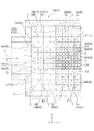
- 1 is an overall schematic side sectional view of a ceramic component according to Embodiment 1 of the present invention.
- the ceramic component 1A (1) according to the first embodiment is a ceramic component used in an exhaust gas treatment apparatus for a gasoline engine vehicle.
- the ceramic component 1A of the present embodiment includes a base body 2 made of a ceramic material and a plurality of first parts that are provided on the base body 2 and through which a fluid 5 that is high-temperature exhaust gas passes from one side 3 to the other side 4 of the base body 2. It has the flow path 6 and the reaction participating member 8 (FIG. 2) provided in the inner surface 7 (FIG. 2) of the first flow path 6. And the 1st flow path 6 is comprised so that flow path resistance may become large toward the downstream (the other side 4) from the upstream (one side 3) in the direction through which the fluid 5 passes.
- the reaction participating member 8 has a function related to the progress of a desired chemical reaction in contact with the fluid 5 passing through the first flow path 6.
- the gasoline vehicle used for the exhaust gas purification process In this embodiment, the gasoline vehicle used for the exhaust gas purification process.
- Three-way catalyst Pt—Rh—Pd, Pt—Rh—CeO 2, etc.
- the three-way catalyst (8) is provided on the inner surface 7 of the substrate 2 so as to be included in the alumina coat layer 9.
- the reaction participating member 8 is not limited to the three-way catalyst.
- the “flow path resistance” means the ease or difficulty of passage of the fluid 5 through the first flow path 6, and the flow path having a large flow resistance is difficult for the fluid 5 to pass.
- the fluid 5 tends to pass through the flow path having a small resistance.
- the flow path cross-sectional area is large on the upstream side in the flow direction of the fluid 5, and in other words, the flow path inner diameter is formed large, and on the downstream side in the fluid flow direction, the flow path cross-sectional area is smaller than that on the upstream side. In other words, the inner diameter of the flow path is smaller than that of the upstream side.
- the flow resistance of the first flow path 6 increases from the upstream side (one side 3) to the downstream side (the other side 4) in the direction in which the fluid 5 passes.
- the fluid 5 such as exhaust gas flowing into the flow path at a high temperature passes at a high speed because the flow path resistance is small on the inlet side (one side 3) of the flow path 6, that is, the upstream side in the flow direction.
- the outlet side (the other side 4) of the flow path that is, the downstream side passes through at a low speed because the flow path resistance is larger than the upstream side.
- the amount of heat transferred from the high-temperature fluid to the ceramic component 1A is reduced in the upstream portion of the flow path 6 and moves to the downstream side of the flow path 6 with the temperature drop of the fluid 5 suppressed.
- the amount of heat transfer increases as the passage speed of the fluid 5 decreases.
- the first flow path 6 has a plurality of second flows through which the fluid 5 passes in the direction (Y direction and Z direction) intersecting the direction (X direction) from the one side 3 toward the other side 4.
- a path 6 is also provided.
- first flow path 6A when the first flow path 6 and the second flow path 6 are distinguished, they are referred to as “first flow path 6A” and “second flow path 6B”.
- the fluid 5 flowing along the first flow path 6A is referred to as “fluid 5A”
- the fluid flowing along the second flow path 6B is referred to as “fluid 5B”.
- the 2nd flow path 6B is comprised so that flow path resistance may become large toward the downstream from the upstream in the direction through which the fluid 5B passes.
- the size of the lattice indicating each flow path surrounded by the substrate 2 represents the size of the flow path resistance easily.
- the flow path is connected in the direction in which the fluid 5 flows (reference numerals 5A and 5B in FIG. 1).
- reference numeral 10 denotes a ceramic component housing.
- the flow resistance of the second flow path 6B also increases from the upstream side to the downstream side in the direction in which the fluid 5 passes.
- the high temperature deterioration of the upstream part of a flow path can be suppressed.
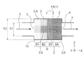
- the diameter R1 (FIG. 3) of the inlet portion of the fluid 5 of the ceramic component 1A is the same as that of the main body portion (portion where a plurality of flow paths exist) of the ceramic component 1A. This is particularly effective when the structure is smaller than the diameter R2 (FIG. 3).
- the base body 2 is configured in a block overlapping structure B in which a plurality (four) of blocks B1, B2, B3, and B4 are stacked from one side 3 to the other side 4.
- the four blocks B1, B2, B3, and B4 are configured so that the flow path resistance is different for each block.
- the next-stage block B2 has a larger flow resistance in the direction from the one side 3 to the other side 4 (X direction) than the most upstream block B1.
- the relationship between the other blocks B3 and B4 is the same, and the subsequent block is configured to have a larger flow path resistance than the preceding block.
- each block it is comprised so that flow-path resistance may differ in the direction (Y direction and Z direction) which cross
- FIG. 3 each block has a central portion (in FIG. 3, the “middle” portion when divided into three parts, upper, middle, and lower). (The “upper” and “lower” portions in FIG. 3 divided into upper, middle, and lower) are configured to have a smaller flow resistance than the central portion.
- the block overlap structure is a state in which a plurality of blocks B1, B2, B3, and B4 are overlapped, the block B1, B2, B3, and B4 are described for each of the blocks B1, B2, B3, and B4.
- the ceramic component 1A having the above structure can be easily manufactured.
- the detailed manufacturing method of 1 A of ceramic components of the structure of Embodiment 1 is mentioned later.
- Embodiment 2 (see FIG. 4) ⁇
- the ceramic component 1B (1) according to the second embodiment is partially different from the ceramic component 1A according to the first embodiment in the configuration for reducing the influence of the temperature distribution in the fluid flow direction and the type of the reaction participating member.
- the other basic configuration is the same as that of the first embodiment. Therefore, the description of the same configuration as that of the first embodiment is omitted here, and the configuration and operation unique to the second embodiment that are different from the first embodiment will be described.
- the reaction participating member 8 is configured such that the characteristics change from high temperature activity to low temperature activity from the upstream side to the downstream side in the direction in which the fluid 5 passes. That is, the high temperature active reaction participating member 8 is positioned upstream of the first flow path 6 and the low temperature active reaction participating member 8 is positioned downstream. Specifically, four reaction participating members 8A, 8B, 8C, and 8D having different high-temperature characteristics are provided from the upstream side to the downstream side of the first flow path 6. The reaction participation member 8A has the highest high temperature activity, and the reaction participation member 8D has the lowest high temperature activity and the lowest low temperature activity.
- the flow path resistance of the first flow path 6 is not different as in the first embodiment, and is configured uniformly in the direction in which the fluid 5 flows.
- a material having high high-temperature activity as a reaction-participating member exhibits high activity without denaturation of the member even at high temperatures.
- a material having a high low temperature activity exhibits a high activity in a low temperature region than the high temperature.
- the reaction participating member 8 changes its characteristic from the high temperature activity to the low temperature activity from the upstream side to the downstream side in the direction in which the fluid 5 passes. Therefore, even if the temperature distribution occurs, the reaction participating member 8A. , 8B, 8C, and 8D are hardly affected by the temperature distribution. That is, the upstream portion is in contact with the fluid 5 having the highest temperature, but the reaction participating member 8A in this portion has a high temperature active characteristic, so that an effective process is performed. The temperature of the fluid 5 is lowered by heat transfer as it goes downstream, but the downstream portion is provided with a low-temperature active reaction member 8D, so that effective treatment is performed at the lowered temperature. . Thereby, the influence of the temperature distribution in the direction in which the fluid 5 flows can be reduced, and stabilization of processing such as exhaust gas purification by the reaction participating member 8 can be promoted.
- the first flow path 6 has the fluid 5 in the direction (Y direction and Z direction) intersecting the direction (X direction) from the one side 3 toward the other side 4.
- a plurality of second flow paths 6 that pass therethrough are also provided.
- the structure of the first flow path 6A and the second flow path 6B is different from that of the first embodiment in that the flow path resistance is uniform, but the other structures are the same.
- the second flow path 6B is also configured such that the characteristic of the reaction participating member 8 changes from the low temperature activity to the high temperature activity from the upstream side to the downstream side in the direction in which the fluid 5 passes.
- the central portion of the substrate 2 the “medium” portion in FIG.
- the peripheral part when divided into three parts, upper, middle, and lower is a high-temperature active reaction participating member 8. Yes, the peripheral part ("upper” and “lower” parts when divided into three parts, upper, middle, and lower in FIG. 4) is provided with a low-temperature active reaction participation member 8 having lower high-temperature activity than the central part. ing.
- the characteristics of the reaction participating member 8 change from the high temperature activity to the low temperature activity from the upstream side to the downstream side in the direction in which the fluid 5B also passes through the second flow path 6B. Therefore, also in the 2nd flow path 6B, the influence of temperature distribution can be reduced and stabilization of processing, such as exhaust gas purification by the reaction participating member 8, can be accelerated
- the base 2 has a block overlapping structure B in which a plurality of (four) blocks B1, B2, B3, B4 are stacked from one side 3 to the other side 4. It is configured.
- the four blocks B1, B2, B3, and B4 are configured so that the characteristics of the reaction participating member are different for each block.
- the next-stage block B2 is provided with a reaction participation member that is active at a lower temperature in the direction from the one side 3 to the other side 4 (X direction) than the most upstream block B1.
- the relationship with the other blocks B3 and B4 is the same, and the reaction block is configured to be activated at a lower temperature in the latter block than in the previous block.
- each block has a central portion (in FIG. 3, “middle” portion when divided into three parts, upper, middle, and lower), which is active at high temperature, and surroundings.
- the “upper” and “lower” parts when divided into three parts, upper, middle, and lower in FIG. 3) are configured such that the high-temperature activity is lower than the central part and the low-temperature activity is achieved.
- the block overlapping structure is a state in which a plurality of blocks B1, B2, B3, and B4 are overlapped, the block B1, B2, B3, and B4 are described for each of the blocks B1, B2, B3, and B4.
- the ceramic component 1B having the above structure can be easily manufactured.
- the detailed manufacturing method of the ceramic component 1B of the structure of Embodiment 2 is mentioned later.
- Embodiment 3 (see FIG. 5) ⁇
- the ceramic component 1C (1) according to the third embodiment has a configuration in which a plurality of bases 2 having different types of reaction-participating members are arranged apart from each other in the direction of fluid flow, according to the first or second embodiment. 1B, and other basic configurations are the same as those in the first or second embodiment. Therefore, the description of the same configuration as that of the first embodiment or the second embodiment is omitted here, and the configuration and operation unique to the third embodiment which are different from those will be described.
- the purification of the gas to be removed in the flow direction of the fluid 5 A structure is employed in which the part for use (oxidation catalyst support part) is arranged in the previous stage and the PM removal part (PM removal filter) is arranged in the subsequent stage.
- the base body 2 is provided with a plurality of base bodies 2A and 2B separately in the direction from the one side to the other side.
- the basic structure of the substrates 2A and 2B is the same as that of the first embodiment. That is, the first flow paths 6 of the base bodies 2A and 2B are configured so that the flow path resistance increases from the upstream side to the downstream side in the direction in which the fluid 5 passes.
- the reaction participation member 8 is a different kind for every base
- the reaction participating member 8E of the base 2A is a catalyst (oxidation catalyst) that has a purification capability for the gas to be removed such as HC, CO, and NOX.
- the reaction participating member 8F of the substrate 2B is a catalyst (particulate filter) having a purification capacity for particulate matter (PM).
- the flow direction of the fluid 2A, the reaction participation member 2A (oxidation catalyst) as a portion for purifying the gas to be removed is disposed in the previous stage, and the reaction participation member 2B (PM removal filter) as the PM removal portion is disposed in the rear stage.
- the reaction participation member 2B PM removal filter
- Embodiment 4 (see FIG. 6) ⁇
- the ceramic part 1D (1) according to the fourth embodiment is different from the ceramic parts 1A and 1B according to the first or second embodiment in that the base 2 is divided into a plurality of parts.
- the base 2 is divided into a plurality of bases 21 and 22 in the direction from the one side to the other side.
- the heat capacity of the ceramic component 1D1 corresponding to the base 21 on the one side 3 is configured to be smaller than the heat capacity of the ceramic component 1D2 corresponding to the other base 22.
- the base 21 is formed smaller than the base 22, and the difference in heat capacity is created by the difference in size.
- the base 2 of the ceramic part 1D is divided into a plurality of bases 21 and 22 from the one side 3 toward the other side 4, and the heat capacity of the ceramic part 1D1 corresponding to the base 21 on the one side 3 Is smaller than the heat capacity of the ceramic part 1D2 corresponding to the other base 22, so that when the fluid 5 flows into the ceramic part 1D at the room temperature at the beginning of the fluid treatment, the part (21) that contacts first has a heat capacity. Since it is small, it rises to an appropriate temperature in a short time (corresponding to cold start), and an effective processing state can be realized in a short time.
- Embodiment 5 (see FIG. 7) ⁇ Next, according to the fifth embodiment, a schematic configuration of a three-dimensional manufacturing apparatus 41 that can be used for manufacturing the ceramic component 1 according to the embodiment, and a book that is executed by using the three-dimensional manufacturing apparatus 41. The content of an example of the three-dimensional manufacturing method of the ceramic component of the invention will be described.
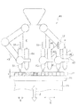
- (1) Schematic configuration of 3D manufacturing equipment As an example of the three-dimensional manufacturing apparatus 41 for manufacturing the ceramic component 1, an articulated industrial robot including a plurality of robot arms 43, 45, and 47 can be employed. Specifically, the first discharge head 51 that discharges the first fluid composition 31 including the ceramic material particles for the substrate 2 and the first material that is a material for the first flow path 6 and that can be heat-dissipated. A second discharge head 53 for discharging the two-fluid composition 33 and a third discharge head 55 for discharging a third fluid composition containing particles of the material for the reaction-participating member are provided.
- a fourth discharge head for discharging a fourth fluid support material including a material for a support material to be used as necessary is provided.
- These ejection heads 51, 53, and 55 are a first ejection unit 51, a second ejection unit 53, and a third ejection unit 55, respectively.
- the heat-dissipative material in the material for the first flow path 6 that can be dissipated by heating is thermally decomposed in the heat treatment for sintering the ceramic particles and disappears to become voids after disappearance.
- It is a material that can form the first flow path 6, and examples thereof include organic substances such as a binder and a pore former.
- the three-dimensional manufacturing apparatus 41 is irradiated with laser light E, which is an example of energy, on the layer 11 formed by the fluid compositions 31, 33, and 37 discharged from the discharge heads 51, 53, and 55.
- laser light E which is an example of energy
- the three-dimensional manufacturing apparatus 41 is used for manufacturing the ceramic component 1 by including these members as an example.
- the three-dimensional manufacturing method of a ceramic part according to the fifth embodiment includes a base 2 made of a ceramic material, and a plurality of first parts provided on the base 2 and through which the fluid 5 passes from one side 3 to the other side 4 of the base 2.
- (A) Layer formation step (see FIG. 7)
- the first fluid composition 31 containing the ceramic material particles for the substrate 2 is discharged from the first discharge portion 51 to a portion corresponding to the substrate 2, and is a material for the first flow path 6.
- the second flowable composition 33 containing a material that can be lost by heating is discharged from the second discharge portion 53 to a portion corresponding to the first flow path 6, the first flow path 6 formed by the loss of heating is the fluid 5.
- a third fluid composition containing particles of a material for the reaction-participating member 8 that is discharged so that the flow path resistance increases (the cross-sectional area of the flow path decreases) from the upstream side 3 to the downstream side 4 in the passing direction.
- the material 37 is discharged from the third discharge portion 55 to the site corresponding to the reaction participating member 8 to form one layer 11.
- the discharge to the site corresponding to the reaction participating member 8 is the position between the second fluid composition (including a material that can be lost by heating) 33 and the first fluid composition 31, that is, the first flow. This is the position corresponding to the inner surface 7 of the path 6.
- a fourth fluid support material containing a material for a support material is supplied from a fourth discharge head to a predetermined portion as necessary to form one layer D. .
- all of the three types of discharge units 51, 53, and 55 are configured by the discharge heads 51, 53, and 55, respectively, and all of the three types of flowable compositions 31, 33, and 37 are used. It is comprised so that it may discharge in a droplet state.
- the three types of ejection units 51, 53, and 55 do not necessarily have to be constituted by ejection heads, and some or all of these may be constituted by other means (for example, a coating roller) having a different structure. Is also possible.
- the ceramic material is not limited to that described in the first embodiment, and various kinds of particles such as various metals and metal compounds shown below can be applied depending on the use conditions and applications.
- various metals such as aluminum, titanium, iron, copper, magnesium, stainless steel, maraging steel, etc.
- various metal oxides such as silica, alumina, titanium oxide, zinc oxide, zircon oxide, tin oxide, magnesium oxide, potassium titanate, etc.
- Metal nitrides such as silicon nitride, titanium nitride and aluminum nitride; various metal carbides such as silicon carbide and titanium carbide; various metal sulfides such as zinc sulfide; carbonates of various metals such as calcium carbonate and magnesium carbonate; Sulfates of various metals such as calcium sulfate and magnesium sulfate, silicates of various metals such as calcium silicate and magnesium silicate, phosphates of various metals such as calcium phosphate, various metals such as aluminum borate and magnesium borate Borate and their composites, gypsum (calcium sulfate hydrates, sulfuric acid Anhydrides of calcium) and the like.
- various metal carbides such as silicon carbide and titanium carbide
- various metal sulfides such as zinc sulfide
- carbonates of various metals such as calcium carbonate and magnesium carbonate
- Sulfates of various metals such as calcium sulfate and magnesium sulfate
- each fluid composition 31, 33, 37 generally contains a solvent or dispersion medium and a binder in addition to the particles of the three kinds of materials 21, 23, 35 described above.
- the solvent or dispersion medium include various waters such as distilled water, pure water, and RO water, and methanol, ethanol, 2-propanol, 1-butanol, 2-butanol, octanol, ethylene glycol, diethylene glycol, glycerin, and the like.
- Alcohols such as ethylene glycol monomethyl ether (methyl cellosolve) (cellosolves), esters such as methyl acetate, ethyl acetate, butyl acetate, ethyl formate, acetone, methyl ethyl ketone, diethyl ketone, methyl isobutyl ketone, methyl isopropyl ketone , Ketones such as cyclohexanone, aliphatic hydrocarbons such as pentane, hexane and octane, cyclic hydrocarbons such as cyclohexane and methylcyclohexane, benzene, toluene, xylene, hexylbenzene and hebutylbenzene Aromatic hydrocarbons with long-chain alkyl groups and benzene rings such as zen, octylbenzene, nonylbenzene, decylbenzene
- the binder is not limited as long as it is soluble in the aforementioned solvent or dispersion medium.
- an acrylic resin, an epoxy resin, a silicone resin, a cellulose resin, a synthetic resin, or the like can be used.
- thermoplastic resins such as PLA (polylactic acid), PA (polyamide), PPS (polyphenylene sulfide) can be used.
- PLA polylactic acid
- PA polyamide
- PPS polyphenylene sulfide
- the material that can be heat-dissipated include the above-described solvents or dispersion media, and binders.
- the layer formation process is repeated in the lamination direction Z.
- the layer forming process is repeated a predetermined number of times in the stacking direction Z to form a desired three-dimensional ceramic component precursor in which a plurality of layers 11 are stacked.
- energy is applied to the ceramic component precursor in a state where the layer 11 is laminated, and the material that can be heat-dissipated is heat-dissipated to form the first flow path 6 and the particles are solidified to solidify the ceramic component 1. Is shaped.
- the unnecessary support material 25 is removed, and the ceramic component 1 as a product is obtained.
- the ceramic component 1 of Embodiment 1, Embodiment 3, and Embodiment 4 can be manufactured easily.
- the sixth embodiment is an example of a three-dimensional manufacturing method of a ceramic component that can be used to manufacture the ceramic component 1B according to the second embodiment. Basically, since most of the parts are the same as those in the fifth embodiment, description of those parts is omitted, and only the parts unique to the sixth embodiment will be described.
- the reaction participating member 8 is performed as follows in order to change the characteristics from the high temperature activity to the low temperature activity from the upstream side to the downstream side in the direction in which the fluid 5 passes.
- a first fluid composition 31 containing ceramic material particles for the substrate 2 is discharged from the first discharge portion 51 to a portion corresponding to the substrate 2, and a material that is a material for the first flow path 6 and can be lost by heating.
- the second fluid composition 33 containing the second fluid composition 33 is ejected from the second ejection part 53 to the site corresponding to the first flow path 6, and a plurality of third fluid compositions containing particles of different materials for the reaction participating member 8 are provided.
- the high temperature active reaction participating member 8A is positioned upstream of the first flow path, and the low temperature active reaction participating member 8D is provided.
- One layer 11 is formed by discharging so as to be located on the downstream side. And according to the three-dimensional manufacturing method of the ceramic component which concerns on this embodiment comprised in this way, the ceramic component 1 of Embodiment 2 can be manufactured easily.
- the ceramic component 1 and the three-dimensional manufacturing method of the ceramic component according to the present invention are basically based on the configuration as described above, but have a partial configuration within the scope of the present invention. Of course, changes and omissions can be made.
- the application target of the present invention is not limited to a gasoline engine vehicle or a diesel engine vehicle, but can be applied to other exhaust gas generating vehicles.
- the manufacturing method of discharging the second fluid composition 33 containing the material for the first flow path 6 and including the material that can be lost by heating from the second discharge unit 53 has been described. This heat-dissipable material may be added to the first fluid composition 31 containing ceramic material particles for the substrate 2.
- the layer forming process is as follows. Discharging the first fluid composition 31 containing the ceramic material particles for the substrate 2 and the material for the first flow path 6 and capable of being heat-dissipated from the first discharge portion 51 to the portion corresponding to the substrate 2; In addition, the first flow path 6 formed by the disappearance of heat is discharged from the upstream side to the downstream side in the direction in which the fluid 5 passes so that the flow path resistance increases (so that the cross-sectional area of the flow path decreases). One layer 11 is formed.
- This manufacturing method utilizes the fact that the size of the gaps (pores) formed between the particles varies depending on the particle size of the material particles of the substrate 2. This can be achieved by adjusting the particle diameter of the material particles of the substrate 2 and adjusting the mixing ratio of the heat-extinguishable material so that the pores are connected to form a flow path.
- the material for the reaction participating member 8 is made to adhere to the inner surface of the first flow path by forming a ceramic component precursor without the reaction participating member 8 and then impregnating and drying and solidifying it. You can also.
- the heating source for the solidification step is not limited to laser light, and may be heated in a sintering furnace or the like.
- the flow resistance can be adjusted by filling the flow path with a uniform inner diameter with a mesh material and adjusting the flow resistance by the difference in the filling rate.
- SYMBOLS 1 Ceramic component, 2 ... Base
- Third discharge head (third discharge portion) , 61 ... First irradiation head, 63 ... Second irradiation head, 65 ... Third irradiation head, 71 ... Base plate (layer formation region), 73 ... Stage, P1 ... Layer formation step, E ... Laser light (energy).
Landscapes
- Chemical & Material Sciences (AREA)
- Engineering & Computer Science (AREA)
- Materials Engineering (AREA)
- Chemical Kinetics & Catalysis (AREA)
- Manufacturing & Machinery (AREA)
- Ceramic Engineering (AREA)
- Combustion & Propulsion (AREA)
- Health & Medical Sciences (AREA)
- Mechanical Engineering (AREA)
- Organic Chemistry (AREA)
- Analytical Chemistry (AREA)
- Structural Engineering (AREA)
- General Chemical & Material Sciences (AREA)
- Environmental & Geological Engineering (AREA)
- Biomedical Technology (AREA)
- Oil, Petroleum & Natural Gas (AREA)
- General Engineering & Computer Science (AREA)
- Toxicology (AREA)
- Catalysts (AREA)
- Exhaust Gas After Treatment (AREA)
- Filtering Materials (AREA)
- Processes For Solid Components From Exhaust (AREA)
- Exhaust Gas Treatment By Means Of Catalyst (AREA)
- Porous Artificial Stone Or Porous Ceramic Products (AREA)
- Producing Shaped Articles From Materials (AREA)
Abstract
自動車の排ガス等の高温の流体を処理する際に、該流体の流れる方向における温度分布の影響を低減して処理を行えるようにすることにある。 本発明に係るセラミックス部品は、セラミックス材料で構成される基体と、前記基体に設けられ該基体の一方側から他方側に流体が通過する複数の第1流路と、前記第1流路の内面に設けられた反応関与部材と有するセラミックス部品であって、前記第1流路は前記流体の通過する方向における上流側から下流側に向かって流路抵抗が大きくなることを特徴とする。
Description
本発明は、排ガス等の高温の流体が通過する流路を有し、該流路に排ガス浄化触媒等の反応関与部材が設けられているセラミックス部品及びセラミックス部品の三次元製造方法に関する。
特許文献1には、排ガス浄化用のハニカムフィルタ(セラミックス部品)が記載されている。このハニカムフィルタは排ガスが通過する流路を区画する隔壁を多孔質体にした構造である。そして、この構造のハニカムフィルタを三次元造形法を用いて製造する製造方法が開示されている(0048)。
高温の流体は、セラミックス部品の流路内を通過する際に流路内面との接触により熱がセラミックス部品側に伝熱しつつ該流路の上流側から下流側に流れる。そのため、流体の温度は流路の上流側から下流側に向かって低くなり、温度分布が生じて排ガスの浄化能力が安定しにくい問題があった。また、セラミックス部品の流路の上流側は下流側より高温の流体に晒されるので、該上流側で高温劣化が発生しやすい問題があった。
特許文献1には、前記温度分布の問題については記載も示唆もされていない。
特許文献1には、前記温度分布の問題については記載も示唆もされていない。
本発明の目的は、自動車の排ガス等の高温の流体を処理する際に、該流体の流れる方向における温度分布の影響を低減して処理を行えるようにすることにある。
上記課題を解決するために、本発明に係る第1の態様のセラミックス部品は、セラミックス材料で構成される基体と、前記基体に設けられ該基体の一方側から他方側に流体が通過する複数の第1流路と、前記第1流路の内面に設けられた反応関与部材とを有するセラミックス部品であって、前記第1流路は前記流体の通過する方向における上流側から下流側に向かって流路抵抗が大きくなることを特徴とする。
ここで「反応関与部材」とは、流路を通過する流体と接して所望の化学反応の進行に関わる機能を有するものである。例えば、排ガス浄化処理に用いられる触媒等である。
また、「流路抵抗」とは、第1流路を流体が通過する際の抵抗のことで、流路抵抗が大きい流路は流体が通り難く、流路抵抗が小さい流路は流体が通りやすい。例えば流路断面積が小さい或いは流路内径が小さいと流路抵抗は大きくなり、流路断面積が大きい或いは流路内径が大きいと流路抵抗は小さくなる。
また、「流路抵抗」とは、第1流路を流体が通過する際の抵抗のことで、流路抵抗が大きい流路は流体が通り難く、流路抵抗が小さい流路は流体が通りやすい。例えば流路断面積が小さい或いは流路内径が小さいと流路抵抗は大きくなり、流路断面積が大きい或いは流路内径が大きいと流路抵抗は小さくなる。
本態様によれば、第1流路は前記流体の通過する方向における上流側から下流側に向かって流路抵抗が大きくなるので、高温で流路に流入した排ガス等の流体は、流路の入口側すなわち流れ方向における上流側では流路抵抗が小さいので高速で通過する。一方、流路の出口側すなわち下流側は流路抵抗が上流側より大きいので低速で通過することになる。
従って、前記流路の上流側部分では高温流体から当該セラミックス部品への伝熱量が減り、該流体の温度低下が抑制された状態で流路の下流側に移動する。一方、前記流路の下流側部分では流体の通過速度が低下することにより前記伝熱量が増える。これにより、前記流体の流れる方向における温度分布の影響を低減して前記反応関与部材による排ガス浄化等の処理の安定化を促進することができる。また、流路の上流側部分の高温劣化を抑制することができる。
尚、このような構造のセラミックス部品は、後述する三次元製造方法により容易に製造することができる。
従って、前記流路の上流側部分では高温流体から当該セラミックス部品への伝熱量が減り、該流体の温度低下が抑制された状態で流路の下流側に移動する。一方、前記流路の下流側部分では流体の通過速度が低下することにより前記伝熱量が増える。これにより、前記流体の流れる方向における温度分布の影響を低減して前記反応関与部材による排ガス浄化等の処理の安定化を促進することができる。また、流路の上流側部分の高温劣化を抑制することができる。
尚、このような構造のセラミックス部品は、後述する三次元製造方法により容易に製造することができる。
本発明に係る第2の態様のセラミックス部品は、第1の態様において、前記第1流路は前記一方側から他方側に向かう方向と交差する方向に流体が通過する複数の第2流路を有し、前記第2流路は前記流体の通過する方向における上流側から下流側に向かって流路抵抗が大きくなることを特徴とする。
本態様によれば、第2流路も前記流体の通過する方向における上流側から下流側に向かって流路抵抗が大きくなるので、第2流路においても温度分布の影響を低減して前記反応関与部材による排ガス浄化等の処理の安定化を促進することができる。また、流路の上流側部分の高温劣化を抑制することができる。
尚、この態様は、当該セラミックス部品の流体の入り口部分の口径が、当該セラミックス部品の本体部分(複数の流路が存在する部分)の径より小さい構造の場合に特に有効である。
このような第2流路を備える構造のセラミックス部品も、後述する三次元製造方法により容易に製造することができる。
尚、この態様は、当該セラミックス部品の流体の入り口部分の口径が、当該セラミックス部品の本体部分(複数の流路が存在する部分)の径より小さい構造の場合に特に有効である。
このような第2流路を備える構造のセラミックス部品も、後述する三次元製造方法により容易に製造することができる。
本発明に係る第3の態様のセラミックス部品は、第1の態様又は第2の態様において、前記第1流路と前記第2流路の少なくとも一方は、気孔の連なりにより形成され、気孔率の違いにより前記流体の通過する方向における上流側から下流側に向かって流路抵抗が大きくなることを特徴とする。
ここで、「気孔の連なり」とは当該セラミックス部品を原料粒子を焼結固化して製造した場合に原料粒子同士の間にできる隙間(気孔)が隣の隙間(気孔)と連通した状態になり、その連通によって第1流路等の流路が形成されていることを意味する。
ここで、「気孔の連なり」とは当該セラミックス部品を原料粒子を焼結固化して製造した場合に原料粒子同士の間にできる隙間(気孔)が隣の隙間(気孔)と連通した状態になり、その連通によって第1流路等の流路が形成されていることを意味する。
本態様によれば、原料粒子同士の隙間を利用して第1流路などの流体の流路を形成することができる。
本発明に係る第4の態様のセラミックス部品は、セラミックス材料で構成される基体と、前記基体に設けられ該基体の一方側から他方側に流体が通過する複数の第1流路と、前記第1流路の内面に設けられた反応関与部材とを有するセラミックス部品であって、前記反応関与部材は前記流体の通過する方向における上流側から下流側に向かって高温活性から低温活性に特性が変わることを特徴とする。
本態様によれば、前記反応関与部材は前記流体の通過する方向における上流側から下流側に向かって高温活性から低温活性に特性が変わるので、前記温度分布が生じても反応関与部材の特性によってその温度分布の影響を受けにくくなっている。即ち、前記上流側の部分は最も高温の流体と接するが、該部分の反応関与部材は高温活性の特性のものであるので効果的な処理がなされる。そして、流体は下流に進むにつれて伝熱により温度が下がるが、前記下流側の部分には低温活性の反応関与部材が設けられているので、その低下した温度において効果的な処理がなされる。これにより、前記流体の流れる方向における温度分布の影響を低減して前記反応関与部材による排ガス浄化等の処理の安定化を促進することができる。
尚、このような構造のセラミックス部品は、後述する三次元製造方法により容易に製造することができる。
尚、このような構造のセラミックス部品は、後述する三次元製造方法により容易に製造することができる。
本発明に係る第5の態様のセラミックス部品は、第4の態様において、前記第1流路は前記一方側から他方側に向かう方向と交差する方向に流体が通過する複数の第2流路を有し、前記第2流路は前記流体の通過する方向における上流側から下流側に向かって前記反応関与部材の特性が高温活性から低温活性に変わることを特徴とする。
本態様によれば、第2流路も前記流体の通過する方向における上流側から下流側に向かって前記反応関与部材の特性が高温活性から低温活性に変わるので、第2流路においても温度分布の影響を低減して前記反応関与部材による排ガス浄化等の処理の安定化を促進することができる。
尚、この態様は、当該セラミックス部品の流体の入り口部分の口径が、当該セラミックス部品の本体部分(複数の流路が存在する部分)の径より小さい構造の場合に特に有効である。
このような第2流路を備える構造のセラミックス部品も、後述する三次元製造方法により容易に製造することができる。
尚、この態様は、当該セラミックス部品の流体の入り口部分の口径が、当該セラミックス部品の本体部分(複数の流路が存在する部分)の径より小さい構造の場合に特に有効である。
このような第2流路を備える構造のセラミックス部品も、後述する三次元製造方法により容易に製造することができる。
本発明に係る第6の態様のセラミックス部品は、第1の態様から第5の態様のいずれか一つの態様において、前記基体は、前記一方側から前記他方側に複数のブロックを重ねた状態のブロック重ね構造であり、前記複数のブロックは各ブロック毎に前記流路抵抗又は反応関与部材の特性が異なることを特徴とする。
本態様によれば、複数のブロックを重ねた状態のブロック重ね構造であるので、複数の各ブロック毎に前記流路抵抗又は反応関与部材の特性を変えることで、前記各態様の構造を製造容易に実現することができる。
本発明に係る第7の態様のセラミックス部品は、第1の態様から第6の態様のいずれか一つの態様において、前記反応関与部材は排ガス処理用の触媒であることを特徴とするセラミックス部品。
本態様によれば、前記反応関与部材は排ガス処理用の触媒であるので、自動車(ガソリン車及びディーゼル車)等の排ガス処理用のセラミックス部品に適用すると効果的である。
本発明に係る第8の態様のセラミックス部品は、第1の態様から第7の態様のいずれか一つの態様において、前記基体は前記一方側から他方側に向かう方向において複数設けられ、前記反応関与部材は前記各基体毎に異なる種類であることを特徴とする。
例えばディーゼルエンジン車等のように、排ガス中にHC、CO及びNOX等の除去対象気体の他に粒子状物質(PM)が含まれている場合に、流体の流れ方向において前記除去対象気体の浄化用部分(酸化触媒担持部分)を前段に配置し、前記PM除去部分(PM除去フィルタ)を後段に配置する構造が採用されるが、このような構造のセラミックス部品に本態様を適用すると効果的である。
本発明に係る第9の態様のセラミックス部品は、第1の態様から第6の態様のいずれか一つの態様において、該セラミックス部品の前記基体は前記一方側から他方側に向けて複数に分割され、前記一方側の基体に対応するセラミックス部品の熱容量は他の基体に対応するセラミックス部品の熱容量より小さいことを特徴とする。
本態様によれば、セラミックス部品の前記基体は前記一方側から他方側に向けて複数に分割され、前記一方側の基体に対応するセラミックス部品の熱容量は他の基体に対応するセラミックス部品の熱容量より小さいので、流体処理の開始当初に室温状態の当該セラミックス部品に流体が流入した際に、最初に接触する部分は熱容量が小さいので短時間で適切な温度に上昇し、効果的な処理状態を短時間で実現することができる。
本発明に係る第10の態様のセラミックス部品の三次元製造方法は、セラミックス材料で構成される基体と、前記基体に設けられ該基体の一方側から他方側に流体が通過する複数の第1流路と、前記第1流路の内面に設けられた反応関与部材と、を有するセラミックス部品の三次元製造方法であって、前記基体用のセラミックス材料粒子を含む第1流動性組成物を第1吐出部から前記基体に対応する部位に吐出し、前記第1流路用の材料であって加熱消失可能な材料を含む第2流動性組成物を第2吐出部から前記第1流路に対応する部位に吐出するに際して前記加熱消失によって形成される第1流路が前記流体の通過する方向における上流側から下流側に向かって流路抵抗が大きくなるように吐出し、前記反応関与部材用の材料の粒子を含む第3流動性組成物を第3吐出部から前記反応関与部材に対応する部位に吐出して一つの層を形成する層形成工程と、前記層形成工程を積層方向に繰り返す積層工程と、前記層にエネルギーを付与して前記加熱消失可能な材料を加熱消失させて前記第1流路を形成すると共に前記粒子を固化して前記セラミックス部品を造形する固化工程とを有することを特徴とする。
本態様によれば、第1の態様のセラミックス部品を容易に製造することができる。
本発明に係る第11の態様のセラミックス部品の三次元製造方法は、セラミックス材料で構成される基体と、前記基体に設けられ該基体の一方側から他方側に流体が通過する複数の第1流路と、前記第1流路の内面に設けられた反応関与部材と、を有するセラミックス部品の三次元製造方法であって、前記基体用のセラミックス材料粒子を含む第1流動性組成物を第1吐出部から前記基体に対応する部位に吐出し、前記第1流路用の材料であって加熱消失可能な材料を含む第2流動性組成物を第2吐出部から前記第1流路に対応する部位に吐出し、前記反応関与部材用の異種材料の粒子を含む複数の第3流動性組成物を複数の第3吐出部から前記反応関与部材に対応する部位に吐出するに際して高温活性の反応関与部材が第1流路の上流側に位置し、低温活性の反応関与部材が下流側に位置するように吐出して一つの層を形成する層形成工程と、前記層形成工程を積層方向に繰り返す積層工程と、前記層にエネルギーを付与して前記加熱消失可能な材料を加熱消失させて前記第1流路を形成すると共に前記粒子を固化して前記セラミックス部品を造形する固化工程とを有することを特徴とする。
本態様によれば、第4の態様のセラミックス部品を容易に製造することができる。
以下に、本発明の実施形態に係るセラミックス部品及びセラミックス部品の三次元製造方法について、添付図面を参照して詳細に説明する。
尚、以下の説明では、最初に図1及び図2に表す実施形態1を例にとって、本発明の実施形態1に係るセラミックス部品の構成と、その作用を具体的に説明する。次に図3から図5に個別に表す実施形態2から実施形態4に係る三つの実施形態について、前記実施形態1との差異を中心にセラミックス部品の構成と、その作用を説明する。
次に、本発明の実施形態5に係るセラミックス部品の三次元製造方法の内容を、図6に基づいて該三次元製造方法に使用する三次元製造装置の概略の構成と共に説明する。最後に前記各実施形態と部分的構成を異にする本発明のセラミックス部品及びセラミックス部品の三次元製造方法の他の実施形態について言及する。
尚、以下の説明では、最初に図1及び図2に表す実施形態1を例にとって、本発明の実施形態1に係るセラミックス部品の構成と、その作用を具体的に説明する。次に図3から図5に個別に表す実施形態2から実施形態4に係る三つの実施形態について、前記実施形態1との差異を中心にセラミックス部品の構成と、その作用を説明する。
次に、本発明の実施形態5に係るセラミックス部品の三次元製造方法の内容を、図6に基づいて該三次元製造方法に使用する三次元製造装置の概略の構成と共に説明する。最後に前記各実施形態と部分的構成を異にする本発明のセラミックス部品及びセラミックス部品の三次元製造方法の他の実施形態について言及する。
◆◆◆実施形態1(図1乃至図3参照)◆◆◆
本実施形態1に係るセラミックス部品1A(1)は、ガソリンエンジン車用の排ガス処理装置に用いられるセラミックス部品である。本実施形態のセラミックス部品1Aは、セラミックス材料で構成される基体2と、基体2に設けられ該基体2の一方側3から他方側4に高温の排ガスである流体5が通過する複数の第1流路6と、第1流路6の内面7(図2)に設けられた反応関与部材8(図2)と有する。
そして、第1流路6は流体5の通過する方向における上流側(一方側3)から下流側(他方側4)に向かって流路抵抗が大きくなるように構成されている。
本実施形態1に係るセラミックス部品1A(1)は、ガソリンエンジン車用の排ガス処理装置に用いられるセラミックス部品である。本実施形態のセラミックス部品1Aは、セラミックス材料で構成される基体2と、基体2に設けられ該基体2の一方側3から他方側4に高温の排ガスである流体5が通過する複数の第1流路6と、第1流路6の内面7(図2)に設けられた反応関与部材8(図2)と有する。
そして、第1流路6は流体5の通過する方向における上流側(一方側3)から下流側(他方側4)に向かって流路抵抗が大きくなるように構成されている。
基体2を成すセラミックス材料は、ここではコージェライトが用いられているが、これに限定されず、アルミナ、炭化ケイ素等の他のセラミックス材料も使用できる。
また、反応関与部材8とは、第1流路6を通過する流体5と接して所望の化学反応の進行に関わる機能を有するものであり、本実施形態では、排ガス浄化処理に用いられるガソリン車用の三元触媒(Pt-Rh-Pd、Pt-Rh-CeO2等)である。該三元触媒(8)は、アルミナコート層9に含まれる形で基体2の内面7に設けられている。勿論、反応関与部材8は前記三元触媒に限定されない。
また、「流路抵抗」とは、第1流路6を流体5が通過する際の通り易さ又は通り難さのことで、流路抵抗が大きい流路は流体5が通り難く、流路抵抗が小さい流路は流体5が通りやすい。ここでは、流体5の流れ方向における上流側では流路断面積が大きく、別の言い方では流路内径が大きく形成され、流体の流れ方向における下流側では流路断面積が上流側のものより小さく形成され、別の言い方では流路内径が上流側のものより小さく形成されている。
また、反応関与部材8とは、第1流路6を通過する流体5と接して所望の化学反応の進行に関わる機能を有するものであり、本実施形態では、排ガス浄化処理に用いられるガソリン車用の三元触媒(Pt-Rh-Pd、Pt-Rh-CeO2等)である。該三元触媒(8)は、アルミナコート層9に含まれる形で基体2の内面7に設けられている。勿論、反応関与部材8は前記三元触媒に限定されない。
また、「流路抵抗」とは、第1流路6を流体5が通過する際の通り易さ又は通り難さのことで、流路抵抗が大きい流路は流体5が通り難く、流路抵抗が小さい流路は流体5が通りやすい。ここでは、流体5の流れ方向における上流側では流路断面積が大きく、別の言い方では流路内径が大きく形成され、流体の流れ方向における下流側では流路断面積が上流側のものより小さく形成され、別の言い方では流路内径が上流側のものより小さく形成されている。
上記実施形態1によれば、第1流路6は流体5の通過する方向における上流側(一方側3)から下流側(他方側4)に向かって流路抵抗が大きくなる。これにより、高温で流路に流入した排ガス等の流体5は、流路6の入口側(一方側3)すなわち流れ方向における上流側では流路抵抗が小さいので、高速で通過する。一方、流路の出口側(他方側4)すなわち下流側は流路抵抗が上流側より大きいので、低速で通過することになる。
従って、流路6の上流側部分では高温流体から当該セラミックス部品1Aへの伝熱量が減り、流体5の温度低下が抑制された状態で流路6の下流側に移動する。一方、流路6の下流側部分では流体5の通過速度が低下することにより前記伝熱量が増える。これにより、流体5の流れる方向における温度分布の影響を低減して反応関与部材8による排ガス浄化等の処理の安定化を促進することができる。また、流路6の上流側部分(一方側3)の高温劣化を抑制することができる。
従って、流路6の上流側部分では高温流体から当該セラミックス部品1Aへの伝熱量が減り、流体5の温度低下が抑制された状態で流路6の下流側に移動する。一方、流路6の下流側部分では流体5の通過速度が低下することにより前記伝熱量が増える。これにより、流体5の流れる方向における温度分布の影響を低減して反応関与部材8による排ガス浄化等の処理の安定化を促進することができる。また、流路6の上流側部分(一方側3)の高温劣化を抑制することができる。
更に、本実施形態1では、第1流路6は一方側3から他方側4に向かう方向(X方向)と交差する方向(Y方向及びZ方向)に流体5が通過する複数の第2流路6も設けられている。ここからの説明においては、第1流路6と第2流路6を区別する場合は「第1流路6A」と「第2流路6B」と記す。同様に流体5も第1流路6Aに沿って流れるものを「流体5A」と記し、第2流路6Bに沿って流れるものを「流体5B」と記す。
そして、第2流路6Bは流体5Bの通過する方向における上流側から下流側に向かって流路抵抗が大きくなるように構成されている。図1において、基体2で囲われた各流路を示す格子のサイズの大小は、前記流路抵抗の大小をイメージしやすく表したものである。実際は、流体5が流れる方向(図1の符号5A、5B)に流路はつながっている。
図1と図3において、符号10はセラミックス部品のハウジングである。
そして、第2流路6Bは流体5Bの通過する方向における上流側から下流側に向かって流路抵抗が大きくなるように構成されている。図1において、基体2で囲われた各流路を示す格子のサイズの大小は、前記流路抵抗の大小をイメージしやすく表したものである。実際は、流体5が流れる方向(図1の符号5A、5B)に流路はつながっている。
図1と図3において、符号10はセラミックス部品のハウジングである。
第2流路6Bを有する本実施形態1によれば、第2流路6Bも流体5の通過する方向における上流側から下流側に向かって流路抵抗が大きくなるので、第2流路6Bにおいても温度分布の影響を低減して反応関与部材8による排ガス浄化等の処理の安定化を促進することができる。また、流路の上流側部分の高温劣化を抑制することができる。
尚、第2流路6Bを有する上記構造は、当該セラミックス部品1Aの流体5の入り口部分の口径R1(図3)が、当該セラミックス部品1Aの本体部分(複数の流路が存在する部分)の径R2(図3)より小さい構造の場合に特に有効である。
尚、第2流路6Bを有する上記構造は、当該セラミックス部品1Aの流体5の入り口部分の口径R1(図3)が、当該セラミックス部品1Aの本体部分(複数の流路が存在する部分)の径R2(図3)より小さい構造の場合に特に有効である。
更に、本実施形態1では、基体2は、一方側3から他方側4に複数(4つ)のブロックB1、B2、B3、B4を重ねた状態のブロック重ね構造Bに構成されている。そして、4つのブロックB1、B2、B3、B4は各ブロック毎に前記流路抵抗が異なるように構成されている。
具体的には、最上流側のブロックB1よりも次段のブロックB2の方が、一方側3から他方側4に向かう方向(X方向)において流路抵抗が大きく構成されている。他のブロックB3、B4との関係も同様であり、後段のブロックは前段のブロックよりも流路抵抗が大きくなるように構成されている。
更に各ブロック内で、前記方向Xと交差する方向(Y方向及びZ方向)に流路抵抗が異なるように構成されている。具体的には、図3に表したように、各ブロックはいずれも中央部分(図3において上、中、下と三つに分けたときの「中」の部分)が流路抵抗大、周囲の部分(図3において上、中、下と三つに分けたときの「上」と「下」の部分)が中央部分より流路抵抗小に構成されている。
具体的には、最上流側のブロックB1よりも次段のブロックB2の方が、一方側3から他方側4に向かう方向(X方向)において流路抵抗が大きく構成されている。他のブロックB3、B4との関係も同様であり、後段のブロックは前段のブロックよりも流路抵抗が大きくなるように構成されている。
更に各ブロック内で、前記方向Xと交差する方向(Y方向及びZ方向)に流路抵抗が異なるように構成されている。具体的には、図3に表したように、各ブロックはいずれも中央部分(図3において上、中、下と三つに分けたときの「中」の部分)が流路抵抗大、周囲の部分(図3において上、中、下と三つに分けたときの「上」と「下」の部分)が中央部分より流路抵抗小に構成されている。
ブロック重ね構造Bを有する本実施形態1によれば、複数のブロックB1、B2、B3、B4を重ねた状態のブロック重ね構造であるので、複数の各ブロックB1、B2、B3、B4毎に前記流路抵抗を変えることで、前記構造のセラミックス部品1Aを製造容易に実現することができる。
尚、実施形態1の構造のセラミックス部品1Aの詳細な製造方法は後述する。
尚、実施形態1の構造のセラミックス部品1Aの詳細な製造方法は後述する。
◆◆◆実施形態2(図4参照)◆◆◆
本実施形態2に係るセラミックス部品1B(1)は、流体の流れる方向における温度分布の影響を低減するための構成及び反応関与部材の種類が実施形態1に係るセラミックス部品1Aと一部相違しており、他の基本的構成については実施形態1と同様である。
従って、ここでは実施形態1と同様の構成については説明を省略し、実施形態1と相違する本実施形態2に特有の構成とその作用について説明する。
本実施形態2に係るセラミックス部品1B(1)は、流体の流れる方向における温度分布の影響を低減するための構成及び反応関与部材の種類が実施形態1に係るセラミックス部品1Aと一部相違しており、他の基本的構成については実施形態1と同様である。
従って、ここでは実施形態1と同様の構成については説明を省略し、実施形態1と相違する本実施形態2に特有の構成とその作用について説明する。
本実施形態2に係るセラミックス部品1Bにおいては、反応関与部材8は流体5の通過する方向における上流側から下流側に向かって高温活性から低温活性に特性が変わるように構成されている。即ち、高温活性の反応関与部材8が第1流路6の上流側に位置し、低温活性の反応関与部材8が下流側に位置するように構成されている。
具体的には、第1流路6の上流側から下流側に向かって高温特性の異なる4つの反応関与部材8A、8B、8C、8Dが設けられている。反応関与部材8Aの高温活性が最も高く、反応関与部材8Dの高温活性が最も低く低温活性が最も高くなる関係で設けられている。第1流路6の流路抵抗は実施形態1のように異ならせず、流体5の流れる方向において一様に構成されている。反応関与部材として高温活性が高い材料は、高温であっても部材が変性せず高い活性を示す。また、低温活性が高い材料は、前記高温より低温域において高い活性を示す。
具体的には、第1流路6の上流側から下流側に向かって高温特性の異なる4つの反応関与部材8A、8B、8C、8Dが設けられている。反応関与部材8Aの高温活性が最も高く、反応関与部材8Dの高温活性が最も低く低温活性が最も高くなる関係で設けられている。第1流路6の流路抵抗は実施形態1のように異ならせず、流体5の流れる方向において一様に構成されている。反応関与部材として高温活性が高い材料は、高温であっても部材が変性せず高い活性を示す。また、低温活性が高い材料は、前記高温より低温域において高い活性を示す。
本実施形態2によれば、反応関与部材8は流体5の通過する方向における上流側から下流側に向かって高温活性から低温活性に特性が変わるので、前記温度分布が生じても反応関与部材8A、8B、8C、8Dの特性によってその温度分布の影響を受けにくい。即ち、前記上流側の部分は最も高温の流体5と接するが、該部分の反応関与部材8Aは高温活性の特性のものであるので効果的な処理がなされる。そして、流体5は下流に進むにつれて伝熱により温度が下がるが、前記下流側の部分には低温活性の反応関与部材8Dが設けられているので、その低下した温度において効果的な処理がなされる。これにより、流体5の流れる方向における温度分布の影響を低減して反応関与部材8による排ガス浄化等の処理の安定化を促進することができる。
更に、本実施形態2では、実施形態1と同様に、第1流路6は一方側3から他方側4に向かう方向(X方向)と交差する方向(Y方向及びZ方向)に流体5が通過する複数の第2流路6も設けられている。第1流路6Aと第2流路6Bの構造は、流路抵抗が一様である点が実施形態1と相違するが、その他の構造は同じである。
そして、第2流路6Bも流体5の通過する方向における上流側から下流側に向かって反応関与部材8の特性が低温活性から高温活性に変わるように構成されている。具体的には、図4に表したように、基体2の中央部分(図4において上、中、下と三つに分けたときの「中」の部分)が高温活性の反応関与部材8であり、周囲の部分(図4において上、中、下と三つに分けたときの「上」と「下」の部分)は中央部分より高温活性が低く低温活性の反応関与部材8が設けられている。
そして、第2流路6Bも流体5の通過する方向における上流側から下流側に向かって反応関与部材8の特性が低温活性から高温活性に変わるように構成されている。具体的には、図4に表したように、基体2の中央部分(図4において上、中、下と三つに分けたときの「中」の部分)が高温活性の反応関与部材8であり、周囲の部分(図4において上、中、下と三つに分けたときの「上」と「下」の部分)は中央部分より高温活性が低く低温活性の反応関与部材8が設けられている。
第2流路6Bを有する本実施形態2によれば、第2流路6Bも流体5Bの通過する方向における上流側から下流側に向かって反応関与部材8の特性が高温活性から低温活性に変わるので、第2流路6Bにおいても温度分布の影響を低減して反応関与部材8による排ガス浄化等の処理の安定化を促進することができる。
更に、本実施形態2では、実施形態1と同様に、基体2は、一方側3から他方側4に複数(4つ)のブロックB1、B2、B3、B4を重ねた状態のブロック重ね構造Bに構成されている。そして、4つのブロックB1、B2、B3、B4は各ブロック毎に反応関与部材の特性が異なるように構成されている。
具体的には、最上流側のブロックB1よりも次段のブロックB2の方が、一方側3から他方側4に向かう方向(X方向)において、より低温活性な反応関与部材が設けられている。他のブロックB3、B4との関係も同様であり、後段のブロックは前段のブロックよりも反応関与部材は、より低温活性になるように構成されている。
更に各ブロック内で、前記方向Xと交差する方向(Y方向及びZ方向)に反応関与部材の特性が異なるように構成されている。具体的には、図4に表したように、各ブロックはいずれも中央部分(図3において上、中、下と三つに分けたときの「中」の部分)が高温活性であり、周囲の部分(図3において上、中、下と三つに分けたときの「上」と「下」の部分)が中央部分より高温活性が低く低温活性となるように構成されている。
具体的には、最上流側のブロックB1よりも次段のブロックB2の方が、一方側3から他方側4に向かう方向(X方向)において、より低温活性な反応関与部材が設けられている。他のブロックB3、B4との関係も同様であり、後段のブロックは前段のブロックよりも反応関与部材は、より低温活性になるように構成されている。
更に各ブロック内で、前記方向Xと交差する方向(Y方向及びZ方向)に反応関与部材の特性が異なるように構成されている。具体的には、図4に表したように、各ブロックはいずれも中央部分(図3において上、中、下と三つに分けたときの「中」の部分)が高温活性であり、周囲の部分(図3において上、中、下と三つに分けたときの「上」と「下」の部分)が中央部分より高温活性が低く低温活性となるように構成されている。
ブロック重ね構造Bを有する本実施形態2によれば、複数のブロックB1、B2、B3、B4を重ねた状態のブロック重ね構造であるので、複数の各ブロックB1、B2、B3、B4毎に前記反応関与部材8の特性を変えることで、前記構造のセラミックス部品1Bを製造容易に実現することができる。
尚、実施形態2の構造のセラミックス部品1Bの詳細な製造方法は後述する。
尚、実施形態2の構造のセラミックス部品1Bの詳細な製造方法は後述する。
◆◆◆実施形態3(図5参照)◆◆◆
本実施形態3に係るセラミックス部品1C(1)は、異なる種類の反応関与部材を有する複数の基体2を流体の流れる方向において離間した配置した構成が実施形態1又は実施形態2に係るセラミックス部品1A、1Bと相違しており、その他の基本的構成については実施形態1又は実施形態2と同様である。
従って、ここでは実施形態1又は実施形態2と同様の構成については説明を省略し、それらと相違する本実施形態3に特有の構成とその作用について説明する。
本実施形態3に係るセラミックス部品1C(1)は、異なる種類の反応関与部材を有する複数の基体2を流体の流れる方向において離間した配置した構成が実施形態1又は実施形態2に係るセラミックス部品1A、1Bと相違しており、その他の基本的構成については実施形態1又は実施形態2と同様である。
従って、ここでは実施形態1又は実施形態2と同様の構成については説明を省略し、それらと相違する本実施形態3に特有の構成とその作用について説明する。
ディーゼルエンジン車等のように、排ガス中にHC、CO及びNOX等の除去対象気体の他に粒子状物質(PM)が含まれている場合に、流体5の流れ方向において前記除去対象気体の浄化用部分(酸化触媒担持部分)を前段に配置し、前記PM除去部分(PM除去フィルター)を後段に配置する構造が採用される。
本実施形態3では、基体2は前記一方側から他方側に向かう方向において複数個の基体2A、2Bが別個に設けられている。基体2A、2Bの基本構造は実施形態1のものと同じである。即ち、基体2A、2Bの第1流路6は、流体5の通過する方向における上流側から下流側に向かって流路抵抗が大きくなるように構成されている。
そして、反応関与部材8は各基体2A、2B毎に異なる種類である。具体的は、基体2Aの反応関与部材8Eは、HC、CO及びNOX等の除去対象気体に対して浄化能力のある触媒(酸化触媒)である。基体2Bの反応関与部材8Fは、粒子状物質(PM)に対して浄化能力のある触媒(パーティキュレート・フィルター)である。
そして、反応関与部材8は各基体2A、2B毎に異なる種類である。具体的は、基体2Aの反応関与部材8Eは、HC、CO及びNOX等の除去対象気体に対して浄化能力のある触媒(酸化触媒)である。基体2Bの反応関与部材8Fは、粒子状物質(PM)に対して浄化能力のある触媒(パーティキュレート・フィルター)である。
本実施形態3によれば、ディーゼルエンジン車等のように、排ガス中にHC、CO及びNOX等の除去対象気体の他に粒子状物質(PM)が含まれている場合に、流体の流れ方向において前記除去対象気体の浄化用部分としての反応関与部材2A(酸化触媒)を前段に配置し、前記PM除去部分としての反応関与部材2B(PM除去フィルター)を後段に配置する構造が採用することで、効果的に排ガス浄化を行うことができる。
◆◆◆実施形態4(図6参照)◆◆◆
本実施形態4に係るセラミックス部品1D(1)は、基体2を複数に分割した構成が実施形態1又は実施形態2に係るセラミックス部品1A、1Bと相違しており、その他の基本的構成については実施形態1又は実施形態2と同様である。
従って、ここでは実施形態1又は実施形態2と同様の構成については説明を省略し、それらと相違する本実施形態4に特有の構成とその作用について説明する。
本実施形態4に係るセラミックス部品1D(1)は、基体2を複数に分割した構成が実施形態1又は実施形態2に係るセラミックス部品1A、1Bと相違しており、その他の基本的構成については実施形態1又は実施形態2と同様である。
従って、ここでは実施形態1又は実施形態2と同様の構成については説明を省略し、それらと相違する本実施形態4に特有の構成とその作用について説明する。
本実施形態4では、基体2は前記一方側から他方側に向かう方向において複数個の基体21、22に分割されている。そして、前記一方側3の基体21に対応するセラミックス部品1D1の熱容量は他の基体22に対応するセラミックス部品1D2の熱容量より小さくなるように構成されている。具体的には、基体21は基体22より小さく形成され、この大きさの違いによって熱容量の前記差が作られている。
本実施形態4によれば、セラミックス部品1Dの基体2は一方側3から他方側4に向けて複数個の基体21、22に分割され、一方側3の基体21に対応するセラミックス部品1D1の熱容量は他の基体22に対応するセラミックス部品1D2の熱容量より小さいので、流体処理の開始当初に室温状態の当該セラミックス部品1Dに流体5が流入した際に、最初に接触する部分(21)は熱容量が小さいので短時間で適切な温度に上昇し(コールドスタート対応)、効果的な処理状態を短時間で実現することができる。
◆◆◆実施形態5(図7参照)◆◆◆
次に、本実施形態5によって、前記実施形態に係るセラミックス部品1を製造するのに使用できる三次元製造装置41の概略の構成と、当該三次元製造装置41を使用することによって実行される本発明のセラミックス部品の三次元製造方法の一例の内容を説明する。
次に、本実施形態5によって、前記実施形態に係るセラミックス部品1を製造するのに使用できる三次元製造装置41の概略の構成と、当該三次元製造装置41を使用することによって実行される本発明のセラミックス部品の三次元製造方法の一例の内容を説明する。
(1)三次元製造装置の概略の構成(図7参照)
セラミックス部品1を製造する三次元製造装置41としては、一例として複数本のロボットアーム43、45、47を備えた多関節式の産業用ロボットが採用できる。
具体的には、基体2用のセラミックス材料粒子を含む第1流動性組成物31を吐出する第1吐出ヘッド51と、第1流路6用の材料であって加熱消失可能な材料を含む第2流動性組成物33を吐出する第2吐出ヘッド53と、反応関与部材用の材料の粒子を含む第3流動性組成物を吐出する第3吐出ヘッド55とを備えている。更に必要に応じて使用するサポート材用の材料を含む第4流動性サポート材を吐出する第4吐出ヘッド(図示せず)を備えている。そして、これらの吐出ヘッド51、53、55は、それぞれ第1吐出部51、第2吐出部53、第3吐出部55となっている。
セラミックス部品1を製造する三次元製造装置41としては、一例として複数本のロボットアーム43、45、47を備えた多関節式の産業用ロボットが採用できる。
具体的には、基体2用のセラミックス材料粒子を含む第1流動性組成物31を吐出する第1吐出ヘッド51と、第1流路6用の材料であって加熱消失可能な材料を含む第2流動性組成物33を吐出する第2吐出ヘッド53と、反応関与部材用の材料の粒子を含む第3流動性組成物を吐出する第3吐出ヘッド55とを備えている。更に必要に応じて使用するサポート材用の材料を含む第4流動性サポート材を吐出する第4吐出ヘッド(図示せず)を備えている。そして、これらの吐出ヘッド51、53、55は、それぞれ第1吐出部51、第2吐出部53、第3吐出部55となっている。
ここで、第1流路6用の材料であって加熱消失可能な材料における加熱消失可能な材料とは、セラミックス粒子を焼結する加熱処理において加熱分解されて消失して消失後に空隙となって第1流路6を形成することが可能な材料であり、バインダー等の有機物や造孔材等が挙げられる。
また、三次元製造装置41には、これらの吐出ヘッド51、53、55から吐出された各流動性組成物31、33、37によって形成された層11にエネルギーの一例であるレーザー光Eを照射して焼結固化させる複数の照射ヘッド61、63、65と、各流動性組成物31、33、37が吐出され、その上面に層形成領域となる一例として平板状のベースプレート71を備えたステージ73と、ロボットアーム43、45、47の駆動及びステージ73の積層方向Zの昇降動作を実行する図示しない駆動部と、これらの駆動部の駆動と吐出ヘッド51、53、55から吐出される各流動性組成物31、33、37の吐出制御と、照射ヘッド61、63、65から照射されるレーザー光Eの照射制御を行う図示しない制御部と、を備えている。三次元製造装置41は、一例としてこれらの部材を備えることによって前記セラミックス部品1の製造に使用される。
(2)セラミックス部品の三次元製造方法の内容(図7参照)
本実施形態5に係るセラミックス部品の三次元製造方法は、セラミックス材料で構成される基体2と、基体2に設けられ該基体2の一方側3から他方側4に流体5が通過する複数の第1流路6と、第1流路6の内面に設けられた反応関与部材8と有するセラミックス部品の三次元製造方法であって、層形成工程と、積層工程と、固化工程を有することによって基本的に構成されている。
以下各工程について順番に説明する。
本実施形態5に係るセラミックス部品の三次元製造方法は、セラミックス材料で構成される基体2と、基体2に設けられ該基体2の一方側3から他方側4に流体5が通過する複数の第1流路6と、第1流路6の内面に設けられた反応関与部材8と有するセラミックス部品の三次元製造方法であって、層形成工程と、積層工程と、固化工程を有することによって基本的に構成されている。
以下各工程について順番に説明する。
(A)層形成工程(図7参照)
この層形成工程は、基体2用のセラミックス材料粒子を含む第1流動性組成物31を第1吐出部51から基体2に対応する部位に吐出し、第1流路6用の材料であって加熱消失可能な材料を含む第2流動性組成物33を第2吐出部53から第1流路6に対応する部位に吐出するに際して前記加熱消失によって形成される第1流路6が流体5の通過する方向における上流側3から下流側4に向かって流路抵抗が大きくなる(流路断面積が小さくなる)ように吐出し、反応関与部材8用の材料の粒子を含む第3流動性組成物37を第3吐出部55から反応関与部材8に対応する部位に吐出して一つの層11を形成する工程である。
ここで、反応関与部材8に対応する部位に吐出とは、第2流動性組成物(加熱消失可能な材料を含む)33と第1流動性組成物31との間の位置、即ち第1流路6の内面7に対応する位置である。
更に、本実施形態5では、図示しないが、必要に応じてサポート材用の材料を含む第4流動性サポート材を第4吐出ヘッドから所定部位に供給して一つの層Dを形成している。
この層形成工程は、基体2用のセラミックス材料粒子を含む第1流動性組成物31を第1吐出部51から基体2に対応する部位に吐出し、第1流路6用の材料であって加熱消失可能な材料を含む第2流動性組成物33を第2吐出部53から第1流路6に対応する部位に吐出するに際して前記加熱消失によって形成される第1流路6が流体5の通過する方向における上流側3から下流側4に向かって流路抵抗が大きくなる(流路断面積が小さくなる)ように吐出し、反応関与部材8用の材料の粒子を含む第3流動性組成物37を第3吐出部55から反応関与部材8に対応する部位に吐出して一つの層11を形成する工程である。
ここで、反応関与部材8に対応する部位に吐出とは、第2流動性組成物(加熱消失可能な材料を含む)33と第1流動性組成物31との間の位置、即ち第1流路6の内面7に対応する位置である。
更に、本実施形態5では、図示しないが、必要に応じてサポート材用の材料を含む第4流動性サポート材を第4吐出ヘッドから所定部位に供給して一つの層Dを形成している。
また、本実施形態5では、前記3種類の吐出部51、53、55のすべてをそれぞれ吐出ヘッド51、53、55によって構成し、前記3種類の流動性組成物31、33、37のすべてを液滴状態で吐出するように構成されている。
また、前記3種類の吐出部51、53、55は必ずしも吐出ヘッドによって構成されていなくてもよく、これらの一部又は全部を構造の違う他の手段(例えば塗工ローラーなど)によって構成することも可能である。
また、前記3種類の吐出部51、53、55は必ずしも吐出ヘッドによって構成されていなくてもよく、これらの一部又は全部を構造の違う他の手段(例えば塗工ローラーなど)によって構成することも可能である。
尚、セラミックス材料としては、実施形態1で述べたものに限らず、使用条件や用途等に応じて以下に示す各種金属や金属化合物等の粒子が適用可能である。
例えば、アルミニウム、チタン、鉄、銅、マグネシウム、ステンレス鋼、マルエージング鋼等の各種金属、シリカ、アルミナ、酸化チタン、酸化亜鉛、酸化ジルコン、酸化錫、酸化マグネシウム、チタン酸カリウム等の各種金属酸化物、窒化珪素、窒化チタン、窒化アルミニウム等の各種金属窒化物;炭化珪素、炭化チタン等の各種金属炭化物、硫化亜鉛等の各種金属硫化物、炭酸カルシウム、炭酸マグネシウム等の各種金属の炭酸塩、硫酸カルシウム、硫酸マグネシウム等の各種金属の硫酸塩、ケイ酸カルシウム、ケイ酸マグネシウム等の各種金属のケイ酸塩、リン酸カルシウム等の各種金属のリン酸塩、ホウ酸アルミニウム、ホウ酸マグネシウム等の各種金属のホウ酸塩や、これらの複合化物等、石膏(硫酸カルシウムの各水和物、硫酸カルシウムの無水物)が挙げられる。
例えば、アルミニウム、チタン、鉄、銅、マグネシウム、ステンレス鋼、マルエージング鋼等の各種金属、シリカ、アルミナ、酸化チタン、酸化亜鉛、酸化ジルコン、酸化錫、酸化マグネシウム、チタン酸カリウム等の各種金属酸化物、窒化珪素、窒化チタン、窒化アルミニウム等の各種金属窒化物;炭化珪素、炭化チタン等の各種金属炭化物、硫化亜鉛等の各種金属硫化物、炭酸カルシウム、炭酸マグネシウム等の各種金属の炭酸塩、硫酸カルシウム、硫酸マグネシウム等の各種金属の硫酸塩、ケイ酸カルシウム、ケイ酸マグネシウム等の各種金属のケイ酸塩、リン酸カルシウム等の各種金属のリン酸塩、ホウ酸アルミニウム、ホウ酸マグネシウム等の各種金属のホウ酸塩や、これらの複合化物等、石膏(硫酸カルシウムの各水和物、硫酸カルシウムの無水物)が挙げられる。
また、各流動性組成物31、33、37には、前述した3種類の材料21、23、35の粒子の他に溶媒又は分散媒とバインダーとが一般に含まれている。
溶媒又は分散媒としては、例えば、蒸留水、純水、RO水等の各種水の他、メタノール、エタノール、2-プロパノール、1-ブタノール、2-ブタノール、オクタノール、エチレングリコール、ジエチレングリコール、グリセリン等のアルコール類、エチレングリコールモノメチルエーテル(メチルセロソルブ)等のエーテル類(セロソルブ類)、酢酸メチル、酢酸エチル、酢酸ブチル、ギ酸エチル等のエステル類、アセトン、メチルエチルケトン、ジエチルケトン、メチルイソブチルケトン、メチルイソプロピルケトン、シクロヘキサノン等のケトン類、ペンタン、ヘキサン、オクタン等の脂肪族炭化水素類、シクロヘキサン、メチルシクロヘキサン等の環式炭化水素類、ベンゼン、トルエン、キシレン、ヘキシルベンゼン、ヘブチルベンゼン、オクチルベンゼン、ノニルベンゼン、デシルベンゼン、ウンデシルベンゼン、ドデシルベンゼン、トリデシルベンゼン、テトラデシルベンゼン等の長鎖アルキル基及びベンゼン環を有する芳香族炭火水素類、塩化メチレン、クロロホルム、四塩化炭素、1,2-ジクロロエタン等のハロゲン化炭化水素類、ピリジン、ピラジン、フラン、ピロール、チオフェン、メチルピロリドンのいずれか一つを含む芳香族複素環類、アセトニトクル、プロピオニトリル、アクリロニトリル等のニトリル類、N,N-ジメチルアミド、N,N-ジメチルアセトアミド等のアミド類、カルボン酸塩又はその他の各種油類等が挙げられる。
溶媒又は分散媒としては、例えば、蒸留水、純水、RO水等の各種水の他、メタノール、エタノール、2-プロパノール、1-ブタノール、2-ブタノール、オクタノール、エチレングリコール、ジエチレングリコール、グリセリン等のアルコール類、エチレングリコールモノメチルエーテル(メチルセロソルブ)等のエーテル類(セロソルブ類)、酢酸メチル、酢酸エチル、酢酸ブチル、ギ酸エチル等のエステル類、アセトン、メチルエチルケトン、ジエチルケトン、メチルイソブチルケトン、メチルイソプロピルケトン、シクロヘキサノン等のケトン類、ペンタン、ヘキサン、オクタン等の脂肪族炭化水素類、シクロヘキサン、メチルシクロヘキサン等の環式炭化水素類、ベンゼン、トルエン、キシレン、ヘキシルベンゼン、ヘブチルベンゼン、オクチルベンゼン、ノニルベンゼン、デシルベンゼン、ウンデシルベンゼン、ドデシルベンゼン、トリデシルベンゼン、テトラデシルベンゼン等の長鎖アルキル基及びベンゼン環を有する芳香族炭火水素類、塩化メチレン、クロロホルム、四塩化炭素、1,2-ジクロロエタン等のハロゲン化炭化水素類、ピリジン、ピラジン、フラン、ピロール、チオフェン、メチルピロリドンのいずれか一つを含む芳香族複素環類、アセトニトクル、プロピオニトリル、アクリロニトリル等のニトリル類、N,N-ジメチルアミド、N,N-ジメチルアセトアミド等のアミド類、カルボン酸塩又はその他の各種油類等が挙げられる。
バインダーとしては、前述した溶媒又は分散媒に可溶であれば、限定されない。例えば、アクリル樹脂、エポキシ樹脂、シリコーン樹脂、セルロース系樹脂、合成樹脂等を用いることができる。また、例えば、PLA(ポリ乳酸)、PA(ポリアミド)、PPS(ポリフェニレンサルファイド)等の熱可塑性樹脂を用いることもできる。
また、可溶状態でなく、上述したアクリル樹脂などの樹脂の微小な粒子の状態で、前述した溶媒又は分散媒中に分散させるようにしてもよい。
加熱消失可能な材料としては、上述した溶媒又は分散媒、バインダー等が挙げられる。
また、可溶状態でなく、上述したアクリル樹脂などの樹脂の微小な粒子の状態で、前述した溶媒又は分散媒中に分散させるようにしてもよい。
加熱消失可能な材料としては、上述した溶媒又は分散媒、バインダー等が挙げられる。
(B)積層工程と固化工程
前記層形成工程に続いて、該層形成工程を積層方向Zに繰り返す。層形成工程を積層方向Zに所定回数、繰り返して層11が複数積層された所望の三次元形状のセラミックス部品の前駆体を成形する。その後に、層11が積層された状態のセラミックス部品前駆体にエネルギーを付与して前記加熱消失可能な材料を加熱消失させて第1流路6を形成すると共に前記粒子を固化してセラミックス部品1を造形する。不要なサポート材25を取り除いて製品としてのセラミックス部品1となる。
そして、このようにして構成される本実施形態に係るセラミックス部品の三次元製造方法によれば、実施形態1、実施形態3、実施形態4のセラミックス部品1を容易に製造することができる。
前記層形成工程に続いて、該層形成工程を積層方向Zに繰り返す。層形成工程を積層方向Zに所定回数、繰り返して層11が複数積層された所望の三次元形状のセラミックス部品の前駆体を成形する。その後に、層11が積層された状態のセラミックス部品前駆体にエネルギーを付与して前記加熱消失可能な材料を加熱消失させて第1流路6を形成すると共に前記粒子を固化してセラミックス部品1を造形する。不要なサポート材25を取り除いて製品としてのセラミックス部品1となる。
そして、このようにして構成される本実施形態に係るセラミックス部品の三次元製造方法によれば、実施形態1、実施形態3、実施形態4のセラミックス部品1を容易に製造することができる。
◆◆◆実施形態6◆◆◆
次に、本実施形態6は、実施形態2に係るセラミックス部品1Bを製造するのに使用できるセラミックス部品の三次元製造方法の一例である。
基本的には実施形態5と同様の部分がほとんどであるので、その部分の説明は省略し、本実施形態6に特有の部分について説明する。
本実施形態6では、反応関与部材8は流体5の通過する方向における上流側から下流側に向かって高温活性から低温活性に特性が変わるようにするために、以下のように行われる。
次に、本実施形態6は、実施形態2に係るセラミックス部品1Bを製造するのに使用できるセラミックス部品の三次元製造方法の一例である。
基本的には実施形態5と同様の部分がほとんどであるので、その部分の説明は省略し、本実施形態6に特有の部分について説明する。
本実施形態6では、反応関与部材8は流体5の通過する方向における上流側から下流側に向かって高温活性から低温活性に特性が変わるようにするために、以下のように行われる。
基体2用のセラミックス材料粒子を含む第1流動性組成物31を第1吐出部51から基体2に対応する部位に吐出し、第1流路用6の材料であって加熱消失可能な材料を含む第2流動性組成物33を第2吐出部53から第1流路6に対応する部位に吐出し、反応関与部材8用の異種材料の粒子を含む複数の第3流動性組成物を複数の第3吐出部55,55,…から反応関与部材8に対応する部位に吐出するに際して高温活性の反応関与部材8Aが第1流路の上流側に位置し、低温活性の反応関与部材8Dが下流側に位置するように吐出して一つの層11を形成する。
そして、このようにして構成される本実施形態に係るセラミックス部品の三次元製造方法によれば、実施形態2のセラミックス部品1を容易に製造することができる。
そして、このようにして構成される本実施形態に係るセラミックス部品の三次元製造方法によれば、実施形態2のセラミックス部品1を容易に製造することができる。
〔他の実施形態〕
本発明に係るセラミックス部品1及びセラミックス部品の三次元製造方法は、以上述べたような構成を有することを基本とするものであるが、本願発明の要旨を逸脱しない範囲内での部分的構成の変更や省略等を行うことも勿論可能である。
(1)例えば、本発明の適用対象は、ガソリンエンジン車やディーゼルエンジン車に限定されず、他の排ガスを発生するものにも適用可能である。
(2)上記の実施形態では、第1流路用6の材料であって加熱消失可能な材料を含む第2流動性組成物33を第2吐出部53から吐出する製造方法を説明したが、この加熱消失可能な材料は、基体2用のセラミックス材料粒子を含む第1流動性組成物31の中に加えてもよい。この場合は、層形成工程は以下のようにする。
基体2用のセラミックス材料粒子と第1流路6用の材料であって加熱消失可能な材料を含む第1流動性組成物31を第1吐出部51から基体2に対応する部位に吐出し、且つ加熱消失によって形成される第1流路6が流体5の通過する方向における上流側から下流側に向かって流路抵抗が大きくなるように(流路断面積が小さくなるように)吐出して一つの層11を形成する。そして、積層工程後に、層11にエネルギーを付与して加熱消失可能な材料を加熱消失させて前記第1流路を形成すると共に前記粒子を焼結固化してセラミックス部品を造形する。
この製造方法は、基体2の材料粒子の粒径の大小によって粒子同士の隙間にできる隙間(気孔)のサイズが異なることを利用したものである。基体2の材料粒子の粒径を調整し、更に加熱消可能な材料の混合割合を調整して前記気孔が連なって流路ができるようにすることで実可能である。
(3)反応関与部材8用の材料は、該反応関与部材8の無い状態のセラミックする部品前駆体を造形した後、含浸させ、更に乾燥固化させることより第1流路の内面に付着させることもできる。
(4)固化工程の加熱源として、レーザー光に限定されず、焼結炉等で加熱してもよい。
(5)流路抵抗の大小の作り方は、一様な内径の流路にメッシュ材を充填して、その充填率の差によって流路抵抗の大小を調整することも可能である。
本発明に係るセラミックス部品1及びセラミックス部品の三次元製造方法は、以上述べたような構成を有することを基本とするものであるが、本願発明の要旨を逸脱しない範囲内での部分的構成の変更や省略等を行うことも勿論可能である。
(1)例えば、本発明の適用対象は、ガソリンエンジン車やディーゼルエンジン車に限定されず、他の排ガスを発生するものにも適用可能である。
(2)上記の実施形態では、第1流路用6の材料であって加熱消失可能な材料を含む第2流動性組成物33を第2吐出部53から吐出する製造方法を説明したが、この加熱消失可能な材料は、基体2用のセラミックス材料粒子を含む第1流動性組成物31の中に加えてもよい。この場合は、層形成工程は以下のようにする。
基体2用のセラミックス材料粒子と第1流路6用の材料であって加熱消失可能な材料を含む第1流動性組成物31を第1吐出部51から基体2に対応する部位に吐出し、且つ加熱消失によって形成される第1流路6が流体5の通過する方向における上流側から下流側に向かって流路抵抗が大きくなるように(流路断面積が小さくなるように)吐出して一つの層11を形成する。そして、積層工程後に、層11にエネルギーを付与して加熱消失可能な材料を加熱消失させて前記第1流路を形成すると共に前記粒子を焼結固化してセラミックス部品を造形する。
この製造方法は、基体2の材料粒子の粒径の大小によって粒子同士の隙間にできる隙間(気孔)のサイズが異なることを利用したものである。基体2の材料粒子の粒径を調整し、更に加熱消可能な材料の混合割合を調整して前記気孔が連なって流路ができるようにすることで実可能である。
(3)反応関与部材8用の材料は、該反応関与部材8の無い状態のセラミックする部品前駆体を造形した後、含浸させ、更に乾燥固化させることより第1流路の内面に付着させることもできる。
(4)固化工程の加熱源として、レーザー光に限定されず、焼結炉等で加熱してもよい。
(5)流路抵抗の大小の作り方は、一様な内径の流路にメッシュ材を充填して、その充填率の差によって流路抵抗の大小を調整することも可能である。
1…セラミックス部品、2…基体、3…一方側、4…他方側、5…流体、6…第1流路、第2流路、7…内面、8…反応関与部材、9…セラミックスコート層、10…ハウジング、11…層、31…第1流動性組成物、33…第2流動性組成物、35…第5材料、37…第3流動性組成物、41…三次元製造装置、43…ロボットアーム、45…ロボットアーム、47…ロボットアーム、51…第1吐出ヘッド(第1吐出部)53…第2吐出ヘッド(第2吐出部)、55…第3吐出ヘッド(第3吐出部)、61…第1照射ヘッド、63…第2照射ヘッド、65…第3照射ヘッド、71…ベースプレート(層形成領域)、73…ステージ、P1…層形成工程、E…レーザー光(エネルギー)。
Claims (11)
- セラミックス材料で構成される基体と、
前記基体に設けられ該基体の一方側から他方側に流体が通過する複数の第1流路と、
前記第1流路の内面に設けられた反応関与部材と、を有するセラミックス部品であって、
前記第1流路は前記流体の通過する方向における上流側から下流側に向かって流路抵抗が大きくなる、ことを特徴とするセラミックス部品。 - 請求項1に記載されたセラミックス部品において、
前記第1流路は前記一方側から他方側に向かう方向と交差する方向に流体が通過する複数の第2流路を有し、
前記第2流路は前記流体の通過する方向における上流側から下流側に向かって流路抵抗が大きくなる、ことを特徴とするセラミックス部品。 - 請求項1又は2に記載されたセラミックス部品において、
前記第1流路と前記第2流路の少なくとも一方は、
気孔の連なりにより形成され、
気孔率の違いにより前記流体の通過する方向における上流側から下流側に向かって流路抵抗が大きくなる、ことを特徴とするセラミックス部品。 - セラミックス材料で構成される基体と、
前記基体に設けられ該基体の一方側から他方側に流体が通過する複数の第1流路と、
前記第1流路の内面に設けられた反応関与部材と、を有するセラミックス部品であって、
前記反応関与部材は前記流体の通過する方向における上流側から下流側に向かって高温活性から低温活性に特性が変わる、ことを特徴とするセラミックス部品。 - 請求項4に記載されたセラミックス部品において、
前記第1流路は前記一方側から他方側に向かう方向と交差する方向に流体が通過する複数の第2流路を有し、
前記第2流路は前記流体の通過する方向における上流側から下流側に向かって前記反応関与部材の特性が低温活性から高温活性に変わる、ことを特徴とするセラミックス部品。 - 請求項1から5のいずれか一項に記載されたセラミックス部品において、
前記基体は、前記一方側から前記他方側に複数のブロックを重ねた状態のブロック重ね構造であり、
前記複数のブロックは各ブロック毎に前記流路抵抗又は特性が異なる、ことを特徴とするセラミックス部品。 - 請求項1から6のいずれか一項に記載されたセラミックス部品において、
前記反応関与部材は排ガス処理用の触媒である、ことを特徴とするセラミックス部品。 - 請求項1から7のいずれか一項に記載されたセラミックス部品において、
前記基体は前記一方側から他方側に向かう方向において複数設けられ、
前記反応関与部材は前記各基体毎に異なる種類である、ことを特徴とするセラミックス部品。 - 請求項1から7のいずれか一項に記載されたセラミックス部品において、
該セラミックス部品の前記基体は前記一方側から他方側に向けて複数に分割され、
前記一方側の基体に対応するセラミックス部品の熱容量は他の基体に対応するセラミックス部品の熱容量より小さい、ことを特徴とするセラミックス部品。 - セラミックス材料で構成される基体と、
前記基体に設けられ該基体の一方側から他方側に流体が通過する複数の第1流路と、
前記第1流路の内面に設けられた反応関与部材と、を有するセラミックス部品の三次元製造方法であって、
前記基体用のセラミックス材料粒子を含む第1流動性組成物を第1吐出部から前記基体に対応する部位に吐出し、前記第1流路用の材料であって加熱消失可能な材料を含む第2流動性組成物を第2吐出部から前記第1流路に対応する部位に吐出するに際して前記加熱消失によって形成される第1流路が前記流体の通過する方向における上流側から下流側に向かって流路抵抗が大きくなるように吐出し、前記反応関与部材用の材料の粒子を含む第3流動性組成物を第3吐出部から前記反応関与部材に対応する部位に吐出して一つの層を形成する層形成工程と、
前記層形成工程を積層方向に繰り返す積層工程と、
前記層にエネルギーを付与して前記加熱消失可能な材料を加熱消失させて前記第1流路を形成すると共に前記粒子を固化して前記セラミックス部品を造形する固化工程と、を有することを特徴とするセラミックス部品の三次元製造方法。 - セラミックス材料で構成される基体と、
前記基体に設けられ該基体の一方側から他方側に流体が通過する複数の第1流路と、
前記第1流路の内面に設けられた反応関与部材と、を有するセラミックス部品の三次元製造方法であって、
前記基体用のセラミックス材料粒子を含む第1流動性組成物を第1吐出部から前記基体に対応する部位に吐出し、前記第1流路用の材料であって加熱消失可能な材料を含む第2流動性組成物を第2吐出部から前記第1流路に対応する部位に吐出し、前記反応関与部材用の異種材料の粒子を含む複数の第3流動性組成物を複数の第3吐出部から前記反応関与部材に対応する部位に吐出するに際して高温活性の反応関与部材が第1流路の上流側に位置し、低温活性の反応関与部材が下流側に位置するように吐出して一つの層を形成する層形成工程と、
前記層形成工程を積層方向に繰り返す積層工程と、
前記層にエネルギーを付与して前記加熱消失可能な材料を加熱消失させて前記第1流路を形成すると共に前記粒子を固化して前記セラミックス部品を造形する固化工程と、を有することを特徴とするセラミックス部品の三次元製造方法。
Applications Claiming Priority (2)
| Application Number | Priority Date | Filing Date | Title |
|---|---|---|---|
| JP2016-031102 | 2016-02-22 | ||
| JP2016031102A JP2017149593A (ja) | 2016-02-22 | 2016-02-22 | セラミックス部品及びセラミックス部品の三次元製造方法 |
Publications (1)
| Publication Number | Publication Date |
|---|---|
| WO2017145673A1 true WO2017145673A1 (ja) | 2017-08-31 |
Family
ID=59685429
Family Applications (1)
| Application Number | Title | Priority Date | Filing Date |
|---|---|---|---|
| PCT/JP2017/003485 Ceased WO2017145673A1 (ja) | 2016-02-22 | 2017-01-31 | セラミックス部品及びセラミックス部品の三次元製造方法 |
Country Status (3)
| Country | Link |
|---|---|
| JP (1) | JP2017149593A (ja) |
| TW (1) | TW201800368A (ja) |
| WO (1) | WO2017145673A1 (ja) |
Citations (6)
| Publication number | Priority date | Publication date | Assignee | Title |
|---|---|---|---|---|
| JP2003284923A (ja) * | 2002-03-27 | 2003-10-07 | Ngk Insulators Ltd | ハニカム構造体及びその製造方法、並びにそれを使用した触媒体 |
| JP2004168610A (ja) * | 2002-11-21 | 2004-06-17 | Toyota Motor Corp | 三次元形状焼結体の製造方法及び三次元形状焼結体 |
| JP2009233555A (ja) * | 2008-03-26 | 2009-10-15 | Ngk Insulators Ltd | ハニカム構造体 |
| JP2013086289A (ja) * | 2011-10-14 | 2013-05-13 | Konica Minolta Business Technologies Inc | 立体物造形装置及び制御プログラム |
| JP2013212446A (ja) * | 2012-03-30 | 2013-10-17 | Ngk Insulators Ltd | 複合ハニカム構造体 |
| JP2015189666A (ja) * | 2014-03-28 | 2015-11-02 | 日本碍子株式会社 | 多孔質体、ハニカムフィルタ、多孔質体の製造方法、及びハニカムフィルタの製造方法 |
Family Cites Families (2)
| Publication number | Priority date | Publication date | Assignee | Title |
|---|---|---|---|---|
| JP2011194342A (ja) * | 2010-03-19 | 2011-10-06 | Ngk Insulators Ltd | ハニカム構造体およびハニカム触媒体 |
| KR20150015444A (ko) * | 2012-04-23 | 2015-02-10 | 다우 글로벌 테크놀로지스 엘엘씨 | 축방향으로 섹션화된 세라믹 허니콤 조립체 |
-
2016
- 2016-02-22 JP JP2016031102A patent/JP2017149593A/ja not_active Withdrawn
-
2017
- 2017-01-31 WO PCT/JP2017/003485 patent/WO2017145673A1/ja not_active Ceased
- 2017-02-18 TW TW106105416A patent/TW201800368A/zh unknown
Patent Citations (6)
| Publication number | Priority date | Publication date | Assignee | Title |
|---|---|---|---|---|
| JP2003284923A (ja) * | 2002-03-27 | 2003-10-07 | Ngk Insulators Ltd | ハニカム構造体及びその製造方法、並びにそれを使用した触媒体 |
| JP2004168610A (ja) * | 2002-11-21 | 2004-06-17 | Toyota Motor Corp | 三次元形状焼結体の製造方法及び三次元形状焼結体 |
| JP2009233555A (ja) * | 2008-03-26 | 2009-10-15 | Ngk Insulators Ltd | ハニカム構造体 |
| JP2013086289A (ja) * | 2011-10-14 | 2013-05-13 | Konica Minolta Business Technologies Inc | 立体物造形装置及び制御プログラム |
| JP2013212446A (ja) * | 2012-03-30 | 2013-10-17 | Ngk Insulators Ltd | 複合ハニカム構造体 |
| JP2015189666A (ja) * | 2014-03-28 | 2015-11-02 | 日本碍子株式会社 | 多孔質体、ハニカムフィルタ、多孔質体の製造方法、及びハニカムフィルタの製造方法 |
Also Published As
| Publication number | Publication date |
|---|---|
| JP2017149593A (ja) | 2017-08-31 |
| TW201800368A (zh) | 2018-01-01 |
Similar Documents
| Publication | Publication Date | Title |
|---|---|---|
| US10307749B2 (en) | High capacity structures and monoliths via paste imprinting | |
| CN103080046B (zh) | 用于将区别层施加到多孔陶瓷过滤器上的方法 | |
| CN107155311B (zh) | 结合有流动障碍部的切向流分离元件及制造方法 | |
| RU2405948C2 (ru) | Устройство для уменьшения выбросов дибензодиоксина, дибензофурана и твердых частиц | |
| CN102553356B (zh) | 制造过滤设备和制造多孔陶瓷制品的方法 | |
| EP2599534B1 (en) | Diesel particulate filter and method of manufacturing | |
| CN103133093A (zh) | 在柴油机特定的过滤器上的scr及其制备方法 | |
| HK1215690A1 (zh) | 通过添加技术制造过滤膜的方法以及所得到的膜 | |
| JP6633952B2 (ja) | ハニカム構造体 | |
| CN101518705A (zh) | 具有高储存能力和低背压的壁流蜂窝式过滤器 | |
| WO2007119408A1 (ja) | 目封止ハニカム構造体の製造方法 | |
| JP6238791B2 (ja) | 目封止ハニカム構造体 | |
| JP2011125851A (ja) | ハニカム構造体及び排ガス浄化装置 | |
| WO2017141697A1 (ja) | セラミックス部品及びセラミックス部品の三次元製造方法 | |
| CN103415679A (zh) | 多功能废气净化过滤器和使用其的废气净化装置 | |
| WO2017145673A1 (ja) | セラミックス部品及びセラミックス部品の三次元製造方法 | |
| CN105813715A (zh) | 设计为壁式流动过滤器的颗粒过滤器 | |
| JP2015519199A (ja) | 担体空隙埋没型scr触媒構造体 | |
| JP5869407B2 (ja) | 複合ハニカム構造体 | |
| JP7634098B2 (ja) | 可変層厚を有する多層複合材及び関連方法 | |
| US20240317648A1 (en) | Methods of manufacturing green bodies and substrates | |
| KR101488198B1 (ko) | 다기능성 배기가스 정화필터 및 이를 이용한 배기가스 정화장치 | |
| JP2018187548A (ja) | 触媒製造用ハニカム構造体、フィルター型ハニカム触媒および製造方法 | |
| WO2014073065A1 (ja) | ハニカム構造体及びその製造方法 | |
| WO2020115965A1 (ja) | 還元剤噴射装置、排ガス処理装置及び排ガス処理方法 |
Legal Events
| Date | Code | Title | Description |
|---|---|---|---|
| NENP | Non-entry into the national phase |
Ref country code: DE |
|
| 121 | Ep: the epo has been informed by wipo that ep was designated in this application |
Ref document number: 17756115 Country of ref document: EP Kind code of ref document: A1 |
|
| 122 | Ep: pct application non-entry in european phase |
Ref document number: 17756115 Country of ref document: EP Kind code of ref document: A1 |