WO2017145644A1 - 電動工具 - Google Patents
電動工具 Download PDFInfo
- Publication number
- WO2017145644A1 WO2017145644A1 PCT/JP2017/002952 JP2017002952W WO2017145644A1 WO 2017145644 A1 WO2017145644 A1 WO 2017145644A1 JP 2017002952 W JP2017002952 W JP 2017002952W WO 2017145644 A1 WO2017145644 A1 WO 2017145644A1
- Authority
- WO
- WIPO (PCT)
- Prior art keywords
- battery
- switching element
- terminal
- capacitor
- resistor
- Prior art date
- Legal status (The legal status is an assumption and is not a legal conclusion. Google has not performed a legal analysis and makes no representation as to the accuracy of the status listed.)
- Ceased
Links
Images


Classifications
-
- B—PERFORMING OPERATIONS; TRANSPORTING
- B25—HAND TOOLS; PORTABLE POWER-DRIVEN TOOLS; MANIPULATORS
- B25F—COMBINATION OR MULTI-PURPOSE TOOLS NOT OTHERWISE PROVIDED FOR; DETAILS OR COMPONENTS OF PORTABLE POWER-DRIVEN TOOLS NOT PARTICULARLY RELATED TO THE OPERATIONS PERFORMED AND NOT OTHERWISE PROVIDED FOR
- B25F5/00—Details or components of portable power-driven tools not particularly related to the operations performed and not otherwise provided for
-
- H—ELECTRICITY
- H02—GENERATION; CONVERSION OR DISTRIBUTION OF ELECTRIC POWER
- H02J—ELECTRIC POWER NETWORKS; CIRCUIT ARRANGEMENTS OR SYSTEMS FOR SUPPLYING OR DISTRIBUTING ELECTRIC POWER; SYSTEMS FOR STORING ELECTRIC ENERGY
- H02J7/00—Circuit arrangements for charging or discharging batteries or for supplying loads from batteries
Definitions
- the present invention relates to a power tool such as a hammer drill that uses a detachably mounted battery as a power source.
- Patent Document 1 In an electric power tool, it is known to provide a noise removing capacitor between a positive terminal and a negative terminal of a battery that is detachably mounted (the following Patent Document 1). According to this configuration, an effect such as prevention of malfunction of the control circuit can be expected by stabilizing the supply voltage from the battery by the capacitor.
- the voltage remains between the terminals for battery connection due to the influence of the electric charge accumulated in the capacitor. If the battery voltage is high or the capacitor has a large capacity, the current when the terminals for battery connection are short-circuited increases. Therefore, it is desirable that the charge accumulated in the capacitor is small after the battery is removed.
- the present invention has been made in view of such a situation, and an object of the present invention is to provide an electric tool capable of discharging a charge accumulated in a capacitor for stabilizing a supply voltage from a battery when the battery is removed. It is to provide.
- One embodiment of the present invention is a power tool.
- This electric tool has a detachable battery, a capacitor that stabilizes the supply voltage from the battery, an electric motor that operates with the supply voltage from the battery, and a switching element that switches on and off when the battery is removed. And a discharge circuit that discharges the electric charge accumulated in the capacitor when the battery is removed and the switching element is turned on and off.
- the battery includes a first terminal that is one of positive and negative terminals, a second terminal that is the other terminal, and a third terminal provided separately from the first and second terminals,
- the discharge circuit includes a resistor provided at a position between the first and third terminals. When the battery is removed, a voltage applied to the resistor changes to change a voltage at the control terminal of the switching element.
- the switching element may be switched on and off.
- the battery may include a Zener diode provided between the third terminal and the first or second terminal.
- the third terminal may be a protective function terminal.
- the electric motor may be a brushless motor, and may include a control unit that controls driving of the electric motor in accordance with an operation of a switch provided at a position different from a current path from the battery to the electric motor.
- the discharge path by the discharge circuit may be a closed loop including the capacitor, a resistor, and a switching element.
- the switching element of the discharge path may be provided separately from the switching element that is turned on and off by removing the battery, and may be turned on by the voltage of the capacitor itself.
- the electric tool which can discharge the electric charge accumulated in the capacitor
- condenser which stabilizes the supply voltage from a battery when a battery is removed can be provided.
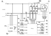
- FIG. 3 is a control block diagram of the hammer drill 1.
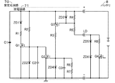
- FIG. 3 is a circuit diagram of the stabilization circuit 70 and the battery 8 in FIG. 2.
- FIG. 6 is a circuit diagram showing another configuration example of the stabilization circuit 70.
- FIG. 1 is a longitudinal sectional view showing the internal structure of a hammer drill 1 according to an embodiment of the present invention.
- a hammer drill 1 that is an example of an electric tool has a main body 2 that forms an outline thereof.
- a tool mounting portion 7 is provided at one end (front end) of the main body 2.
- a tip tool such as a drill blade can be attached to the tool attachment portion 7 in accordance with the work application.
- a handle 11 for an operator to hold is provided on the other end (rear end) of the main body 2 opposite to the one end where the tool mounting portion 7 is provided.
- the handle 11 is provided with a trigger switch 12.
- a battery mounting portion 21 is provided below the handle 11 of the main body 2.
- a battery 8 serving as a power source for driving the motor (electric motor) 3 is detachably mounted on the battery mounting portion 21.
- the battery 8 is attached to the battery attachment portion 21 from the back of the main body 2.
- Each terminal (each terminal) of the battery 8 is electrically connected to each terminal (each terminal) 74 of the main body 2 so that power can be supplied to each circuit of the main body 2.
- the operator operates the trigger switch 12 in a state where the handle 8 is held while the battery 8 is mounted on the battery mounting portion 21 and the tip tool mounted on the tool mounting portion 7 is in contact with the work material. By doing (pulling), various operations (formation of a perforated hole and application of striking force) can be performed by the hammer drill 1.
- the sub handle 15 can be detachably attached to the main body 2 for two-hand work depending on the work application.
- a changeover switch (not shown) for switching the working mode of the hammer drill 1 is provided on the side surface of the main body 2. The operator can switch the operation mode of the hammer drill 1 to any one of the rotation impact mode, the impact mode, and the rotation mode by operating the changeover switch.
- a motor 3 Inside the main body 2, there are a motor 3, a drive transmission unit 4, an impact mechanism unit 5, a reciprocating motion conversion unit 6, a power supply unit 9, a stabilization circuit 70, a main control board 72, a switching control board 73, and an acceleration detection circuit. (Acceleration sensor) 91 is accommodated.
- the motor 3 is accommodated in the lower end portion in the main body 2.
- the motor 3 is disposed such that the rotation shaft 31 extends in the vertical direction, and is supported rotatably with respect to the main body 2.
- the motor 3 is a drive source of the hammer drill 1 and is a brushless motor in the illustrated example.
- a fan 32 is fixed to the upper end of the rotating shaft 31 of the motor 3.
- the drive transmission unit 4 is disposed above the motor 3 in the main body 2.
- the drive transmission unit 4 has an intermediate shaft 41 extending in the front-rear direction.
- the intermediate shaft 41 is supported to be rotatable with respect to the main body 2.
- the intermediate shaft 41 is connected to the rotation shaft 31 of the motor 3 through a plurality of gears, and is rotatable by receiving the rotational force of the motor 3.
- the striking mechanism unit 5 is disposed above the drive transmission unit 4 in the main body 2.
- the striking mechanism unit 5 mainly includes a cylinder 51, a piston 52, a striking element 53, and an intermediate element 54.
- the cylinder 51 has a substantially cylindrical shape extending in the front-rear direction, and is supported on the main body 2 so as to be rotatable with respect to the main body 2.
- the cylinder 51 can be engaged with the intermediate shaft 41 of the drive transmission unit 4, and is configured to be rotatable by receiving the rotational force of the intermediate shaft 41 when engaged with the intermediate shaft 41.
- the front end portion (front end portion) of the cylinder 51 is accommodated in the tool attachment portion 7.
- a piston 52 is slidably disposed in the cylinder 51.
- the piston 52 has a substantially cylindrical shape extending in the front-rear direction.
- the striker 53 is disposed in the piston 52 so as to be slidable in the front-rear direction.
- the intermediate element 54 is disposed in the cylinder 51 so as to be slidable in the front-rear direction in front of the striker 53.
- the front end of the striker 53 can contact the rear end of the intermediate element 54.
- the intermediate element 54 comes into contact with the rear end of the tip tool attached to the tool attachment portion 7.
- the reciprocating motion conversion unit 6 is disposed so as to connect the drive transmission unit 4 and the striking mechanism unit 5.
- the reciprocating motion conversion unit 6 mainly has an arm 61.
- the arm 61 extends in a direction intersecting the intermediate shaft 41 and the cylinder 51, and an upper end portion thereof is connected to a rear end portion of the piston 52 and a lower end portion thereof connected to a rear portion of the intermediate shaft 41 via a plurality of balls.
- the arm 61 is configured to convert the rotational force of the motor 3 transmitted through the intermediate shaft 41 into a linear reciprocating motion in the front-rear direction and transmit it to the piston 52.
- the piston 52 reciprocates back and forth in the cylinder 51.
- the striker 53 reciprocates in the front-rear direction.
- the front end of the striker 53 comes into contact with the rear end of the intermediate piece 54 and strikes the intermediate piece 54.
- the meson 54 hits the front end of the meson 54 hits the rear end of the tip tool attached to the tool mounting portion 7. In this way, a striking force is applied to the tip tool. That is, the output axis of the tool mounting portion 7 coincides with the front-rear direction.
- the rotational force (driving force) of the motor 3 is such that the drive transmission unit 4 and the reciprocating motion conversion unit 6 are driven simultaneously or selectively, so that the striking mechanism unit 5 is rotated, hit, or rotated. Transmitted as power. Thereby, three operation modes of the hammer drill 1 are realized.
- the power supply unit 9 is configured to be able to supply the power supplied from the battery 8 mounted on the battery mounting unit 21 to the outside of the main body 2.
- the power supply unit 9 can supply power to a dust collector (not shown) that can be attached to the main body 2.
- the power supply unit 9 is provided in the vicinity of the motor 3 in the main body 2 and at the front lower end of the main body 2.
- the power supply unit 9 is electrically connected to the battery mounting unit 21.
- the switching control board 73 is equipped with the inverter circuit 80 shown in FIG. 2, converts the DC power supplied from the battery 8 into AC power and supplies the AC power to the motor 3.
- the switching control board 73 is provided with a control signal output circuit 86, a magnetic sensor 87, a rotor position detection circuit 88, and a temperature detection circuit 89 shown in FIG.
- the main control board 72 is equipped with a microcomputer 90 as a control unit shown in FIG. 2 and controls the inverter circuit 80.
- the main control board 72 is provided with a control system power supply circuit 82, a battery voltage detection circuit 83, an overdischarge detection circuit 84, a current detection circuit 85, and a dust collector control circuit 92 shown in FIG.
- the step-down circuit 81 steps down the supply voltage from the battery 8.
- the stabilization circuit 70 has a role of stabilizing the supply voltage from the battery 8.
- the acceleration detection circuit 91 is provided to detect the posture (tilt) of the hammer drill 1.
- the battery remaining amount display circuit 93 has a light emitting unit exposed on the surface of the main body 2 and notifies the operator of the remaining amount of the battery 8.
- FIG. 2 is a control block diagram of the hammer drill 1.
- the stabilization circuit 70 includes a capacitor C ⁇ b> 1 (capacitor) that stabilizes the supply voltage from the battery 8, and a discharge circuit 71.
- the capacitor C1 is, for example, an electrolytic capacitor.
- the discharge circuit 71 is a circuit for discharging the capacitor C1 when the battery 8 is removed. Details of the discharge circuit 71 will be described later.
- the step-down circuit 81 steps down the supply voltage from the battery 8.
- the control system power supply circuit 82 converts the output voltage of the step-down circuit 81 into an operating voltage (for example, 5 V) of the microcomputer 90 and supplies it to the microcomputer 90.
- the trigger switch 12 is provided at a position different from the current path from the battery 8 to the motor 3, and the microcomputer 90 detects the operation of the trigger switch 12 and controls the driving of the motor 3 according to the operation.
- the battery voltage detection circuit 83 detects the voltage of the battery 8 and transmits a battery voltage detection signal to the microcomputer 90.
- the overdischarge detection circuit 84 is connected to the LD terminal (protection function terminal) of the battery 8 and transmits an overdischarge detection signal to the microcomputer 90 when the overdischarge is detected by the voltage of the LD terminal.
- the current detection circuit 85 detects the current flowing through the motor 3 from the voltage across the resistor Rs, and transmits a current detection signal to the microcomputer 90.
- the control signal output circuit 86 outputs a control signal for controlling on / off of each switching element constituting the inverter circuit 80 according to the control of the microcomputer 90.
- the magnetic sensor 87 is an example of a position detection element for detecting the rotational position of the motor 3.
- the rotor position detection circuit 88 detects the rotor position of the motor 3 from the output voltage of each magnetic sensor 87 and transmits a rotor position detection signal to the microcomputer 90.
- the temperature detection circuit 89 detects the temperature of each switching element constituting the inverter circuit 80 and transmits a temperature detection signal to the microcomputer 90.
- the acceleration detection circuit 91 transmits an acceleration detection signal corresponding to the posture (tilt) of the hammer drill 1 to the microcomputer 90.
- the dust collector control circuit 92 controls a dust collector that can be mounted on the hammer drill 1 according to the control of the microcomputer 90.
- the battery remaining amount display circuit 93 performs display corresponding to the remaining amount of the battery 8 under the control of the microcomputer 90.
- FIG. 3 is a circuit diagram of the stabilization circuit 70 and the battery 8 of FIG.
- the circuit configurations of the stabilization circuit 70 and the battery 8 are specifically shown, while the circuits other than the stabilization circuit 70 and the battery 8 shown in FIG. 2 are not shown.
- the capacitor C ⁇ b> 1 is provided between the positive terminal and the negative terminal of the battery 8. That is, one end of the capacitor C1 is connected to the plus terminal of the battery 8, and the other end is connected to the minus terminal and the ground (fixed voltage terminal).
- the positive terminal of the battery 8 is an example of the first terminal
- the negative terminal is an example of the second terminal
- the LD terminal is an example of the third terminal.
- the Zener diode ZD1, the resistor R1, and the switching element Q1 are connected in series between the positive terminal and the negative terminal of the battery 8 so as to be in parallel with the capacitor C1.
- the switching element Q1 is an N-channel MOSFET.
- the cathode of the Zener diode ZD1 is connected to one end of the capacitor C1, and the anode is connected to one end of the resistor R1.
- the other end of the resistor R1 is connected to the drain of the switching element Q1.
- the source of the switching element Q1 is connected to the other end of the capacitor C1.
- the resistor R2 and the Zener diode ZD2 are connected in series between the positive terminal and the negative terminal of the battery 8 so as to be in parallel with the capacitor C1.
- One end of the resistor R2 is connected to one end of the capacitor C1, and the other end is connected to the cathode of the Zener diode ZD2.
- the anode of the Zener diode ZD2 is connected to the other end of the capacitor C1.
- the interconnection point between the resistor R2 and the Zener diode ZD2 is connected to the gate (control terminal) of the switching element Q1.
- the Zener diode ZD2 has a role of preventing the voltage between the gate and source of the switching element Q1 from exceeding a predetermined value.
- the capacitor C2 is provided between the gate of the switching element Q1 and the ground so as to be in parallel with the Zener diode ZD2.
- the capacitor C2 is provided for noise removal.
- the switching element Q2 is provided between the gate of the switching element Q1 and the ground so as to be in parallel with the Zener diode ZD2 and the capacitor C2.
- the switching element Q2 is an N-channel MOSFET.
- the drain of the switching element Q2 is connected to the gate of the switching element Q1.
- the source of the switching element Q2 is connected to the ground.
- the switching element Q3, the resistor R3, and the Zener diode ZD4 are connected in series between the positive terminal and the negative terminal of the battery 8 so as to be in parallel with the capacitor C1.
- the switching element Q3 is a P-channel MOSFET.
- the source of the switching element Q3 is connected to the positive terminal of the battery 8.
- the drain of the switching element Q3 is connected to one end of the resistor R3.
- the other end of the resistor R3 is connected to the cathode of the Zener diode ZD4.
- the anode of the Zener diode ZD4 is connected to the ground.
- the interconnection point of the resistor R3 and the Zener diode ZD4 is connected to the gate (control terminal) of the switching element Q2.
- the Zener diode ZD4 has a role of preventing the voltage between the gate and source of the switching element Q2 from exceeding a predetermined value.
- the capacitor C3 is provided between the gate of the switching element Q2 and the ground so as to be in parallel with the Zener diode ZD4.
- the capacitor C3 is provided for noise removal.
- the resistor R6 and the resistor R7 are connected in series between the gate of the switching element Q2 and the ground so as to be in parallel with the Zener diode ZD4 and the capacitor C3.
- the cathode of the Zener diode ZD3 is connected to the positive terminal of the battery 8.
- the anode of the Zener diode ZD3 is connected to the gate (control terminal) of the switching element Q3.
- the Zener diode ZD3 has a role of preventing the voltage (absolute value) between the gate and source of the switching element Q3 from exceeding a predetermined value.
- the resistor R4 is provided between the positive terminal of the battery 8 and the gate of the switching element Q3 so as to be in parallel with the Zener diode ZD3.
- One end of the resistor R4 is connected to the plus terminal of the battery 8, and the other end is connected to the gate of the switching element Q3 and one end of the resistor R5.
- the other end of the resistor R5 is connected to the LD terminal of the battery 8.
- a Zener diode ZD5 and a Zener diode ZD6 are connected in series between the LD terminal and the negative terminal.
- the cathode of the Zener diode ZD5 is connected to the LD terminal.
- the anode of the Zener diode ZD5 is connected to the cathode of the Zener diode ZD6.
- the anode of the Zener diode ZD6 is connected to the negative terminal.
- the negative terminal is connected to ground.
- the resistor R8 and the switching element Q4 are connected in series between the LD terminal and the negative terminal so as to be in parallel with the Zener diode ZD5 and the Zener diode ZD6.
- the switching element Q4 is an N-channel MOSFET. One end of the resistor R8 is connected to the LD terminal, and the other end is connected to the drain of the switching element Q4. The source of the switching element Q4 is connected to the minus terminal.
- a control signal from a control unit (microcomputer or the like) (not shown) of the battery 8 is input to the gate (control terminal) of the switching element Q4. Specifically, the switching element Q4 is turned on when a high level signal is input to the gate when an abnormality such as overdischarge occurs.
- the resistor R2 is a sufficiently large resistor, and the current flowing through the path via the resistor R2 is very small. For this reason, the electric charge accumulated in the capacitor C1 is not discharged.
- the breakdown voltage (zener voltage)
- the switching element Q1 is turned on.
- the electric charge accumulated in the capacitor C1 is discharged through a path of the Zener diode ZD1, the resistor R1, and the switching element Q1.
- the discharge path of the capacitor C1 is formed by the voltage of the capacitor C1 itself.
- the resistor R2 has a sufficiently large resistance value compared to the resistor R1, and thus the capacitor C1 is discharged mainly in a current path passing through the resistor R1.
- the extent to which the capacitor C1 is discharged is determined by the breakdown voltage of the Zener diode ZD1 or the breakdown voltage of the Zener diode ZD2.
- the capacitor C1 is charged to 40V.
- it is desirable that the capacitor C1 is discharged to about 30V or less.
- the stabilization circuit 70 stabilizes the supply voltage from the battery 8 by the action of the capacitor C1, and when the battery 8 is removed, the charge accumulated in the capacitor C1 is discharged by the discharge circuit 71.
- the voltage appearing at the terminal 74 after being removed can be suppressed. Therefore, the current can be suppressed even when the battery connection terminal 74 is short-circuited when the battery 8 is not attached.
- the battery 8 is attached or removed through a protective function terminal (LD terminal) of the battery 8, and it is not necessary to add a new terminal to the battery 8. Therefore, the capacitor C1 is removed when the battery 8 is removed. It is easy and low-cost to introduce the function of discharging the battery.
- LD terminal protective function terminal
- the hammer drill is exemplified as the power tool.
- the technique of the present invention is applicable not only to the hammer drill but also to all power tools including a capacitor that stabilizes a supply voltage from a detachably mounted battery.
- the specific configuration of the discharge circuit 71 shown in FIG. 3 is an example, and the discharge circuit 71 includes a switching element that switches on and off when the battery 8 is removed, and the capacitor C1 when the battery 8 is detached and the switching element is switched on and off. Any structure may be used as long as a discharge path for discharging the charges accumulated in the electrode is formed.
- a general-purpose switching element (enhancement type FET or the like) can be used and can be configured at low cost.
- the switching element used for the discharge circuit 71 is provided in parallel with the capacitor C1 by using the MOSFET (with a channel in which current flows between the drain and source even when the voltage between the gate and source is 0).
Landscapes
- Engineering & Computer Science (AREA)
- Mechanical Engineering (AREA)
- Portable Power Tools In General (AREA)
Abstract
バッテリからの供給電圧を安定化させるコンデンサに溜まった電荷をバッテリが取り外された場合に放電することの可能な電動工具を提供する。着脱可能なバッテリ8と、バッテリ8からの供給電圧を安定化させるコンデンサC1を有する安定化回路70と、バッテリ8からの供給電圧で動作するモータ3と、を備える電動工具であり、安定化回路70は、バッテリ8が取り外されるとオンオフが切り替わるスイッチング素子を有し、バッテリ8が取り外されて前記スイッチング素子のオンオフが切り替わると、コンデンサC1に溜まった電荷を放電する放電経路が形成される。
Description
本発明は、着脱可能に装着したバッテリを電源とするハンマドリル等の電動工具に関する。
電動工具において、着脱可能に装着したバッテリのプラス端子とマイナス端子の間に、ノイズ除去用のコンデンサを設けることが知られている(下記特許文献1)。この構成によれば、コンデンサによりバッテリからの供給電圧を安定化させることで、制御回路の誤動作防止等の効果が期待できる。
従来の電動工具では、バッテリを取り外した後も、コンデンサに溜まった電荷の影響により、バッテリ接続用の端子間に電圧が残存する。バッテリ電圧が高かったり、コンデンサが大容量だったりすると、バッテリ接続用の端子間がショートした場合の電流が大きくなるため、バッテリ取外し後は、コンデンサに溜まった電荷は少ないことが望ましい。
本発明はこうした状況を認識してなされたものであり、その目的は、バッテリからの供給電圧を安定化させるコンデンサに溜まった電荷をバッテリが取り外された場合に放電することの可能な電動工具を提供することにある。
本発明のある態様は、電動工具である。この電動工具は、着脱可能なバッテリと、前記バッテリからの供給電圧を安定化させるコンデンサと、前記バッテリからの供給電圧で動作する電動モータと、前記バッテリが取り外されるとオンオフが切り替わるスイッチング素子を有し、前記バッテリが取り外されて前記スイッチング素子のオンオフが切り替わると、前記コンデンサに溜まった電荷を放電する放電回路と、を備える。
前記バッテリは、正負いずれか一方の端子である第1端子と、他方の端子である第2端子と、前記第1及び第2端子とは別に設けられた第3端子と、を有し、前記放電回路は、前記第1及び第3端子の間となる位置に設けられた抵抗を備え、前記バッテリが取り外されると、前記抵抗に加わる電圧が変化することにより前記スイッチング素子の制御端子の電圧が変化し、前記スイッチング素子のオンオフが切り替わってもよい。
前記バッテリは、前記第3端子と前記第1又は第2端子との間に設けられたツェナーダイオードを有してもよい。
前記第3端子が保護機能用の端子であってもよい。
前記電動モータがブラシレスモータであり、前記バッテリから前記電動モータへの電流経路とは異なる位置に設けられたスイッチの操作に応じて前記電動モータの駆動を制御する制御部を備えてもよい。
前記放電回路による放電経路は、前記コンデンサと、抵抗と、スイッチング素子と、を含む閉ループであってもよい。
前記放電経路のスイッチング素子は、前記バッテリが取り外されることでオンオフが切り替わるスイッチング素子とは別に設けられ、前記コンデンサ自身の電圧によりオンとされてもよい。
なお、以上の構成要素の任意の組合せ、本発明の表現を方法やシステムなどの間で変換したものもまた、本発明の態様として有効である。
本発明によれば、バッテリからの供給電圧を安定化させるコンデンサに溜まった電荷をバッテリが取り外された場合に放電することの可能な電動工具を提供することができる。
以下、図面を参照しながら本発明の好適な実施の形態を詳述する。図1により、上下前後の各方向を定義する。なお、各図面に示される同一または同等の構成要素、部材等には同一の符号を付し、適宜重複した説明は省略する。また、実施の形態は発明を限定するものではなく例示であり、実施の形態に記述されるすべての特徴やその組み合わせは必ずしも発明の本質的なものであるとは限らない。
図1は、本発明の実施の形態に係るハンマドリル1の内部構造を示す縦断面図である。電動工具の一例であるハンマドリル1は、その外郭をなす本体2を有する。本体2の一端部(前端部)には、工具取付部7が設けられる。工具取付部7には、作業用途に応じて、ドリル刃等の先端工具(図示せず)を取付け可能である。本体2の、工具取付部7が設けられる一端部と反対側の他端部(後端部)には、作業者が把持するためのハンドル11が設けられる。ハンドル11にはトリガスイッチ12が設けられる。
本体2のハンドル11の下部には、バッテリ装着部21が設けられる。バッテリ装着部21には、モータ(電動モータ)3を駆動するための電源となるバッテリ8が着脱自在に装着される。バッテリ8は、本体2の後方からバッテリ装着部21に装着される。バッテリ8の各端子(各ターミナル)は、本体2の各端子(各ターミナル)74に電気的に接続され、本体2の各回路に電力供給が可能となっている。作業者は、バッテリ8がバッテリ装着部21に装着された状態において、ハンドル11を把持し、工具取付部7に装着された先端工具を被削材に当接させた状態でトリガスイッチ12を操作する(引く)ことで、ハンマドリル1による各種作業(穿孔穴の形成や打撃力の印加)を行うことができる。なお、本体2には、作業用途に応じて、両手作業用にサブハンドル15を着脱可能に取り付けることができる。本体2の側面には、ハンマドリル1の作業モードを切り替える切替スイッチ(図示せず)が設けられる。作業者は、切替スイッチを操作することにより、ハンマドリル1の動作モードを、回転打撃モード、打撃モード、回転モードのいずれかに切り替えることができる。
本体2の内部には、モータ3、駆動伝達部4、打撃機構部5、往復運動変換部6、電源供給部9、安定化回路70、メイン制御基板72、スイッチング制御基板73、及び加速度検出回路(加速度センサ)91が収容される。
モータ3は、本体2内の下端部に収容される。モータ3は、その回転軸31が上下方向に延びるように配置され、本体2に対して回転可能に支持される。モータ3は、ハンマドリル1の駆動源であって、図示の例ではブラシレスモータである。モータ3の回転軸31の上端部には、ファン32が固定される。
駆動伝達部4は、本体2内においてモータ3の上方に配置される。駆動伝達部4は、前後方向に延在する中間軸41を有する。中間軸41は、本体2に対して回転可能に支持される。中間軸41は、複数のギアを介してモータ3の回転軸31と接続され、モータ3の回転力を受けて回転可能となっている。
打撃機構部5は、本体2内において駆動伝達部4の上方に配置される。打撃機構部5は、主にシリンダ51、ピストン52、打撃子53、及び中間子54を有する。シリンダ51は、前後方向に延びる略円筒形状を有し、本体2の上部において、本体2に対して回転可能に支持される。シリンダ51は、駆動伝達部4の中間軸41と係合可能であり、中間軸41と係合した場合に中間軸41の回転力を受けて回転可能に構成される。シリンダ51の先端部(前端部)は、工具取付部7内に収容される。また、シリンダ51内には、ピストン52が摺動可能に配置される。ピストン52は、前後方向に延びる略円筒形状を有する。打撃子53は、ピストン52内に前後方向に摺動可能に配置される。中間子54は、シリンダ51内において打撃子53の前方において前後方向に摺動可能に配置される。打撃子53の前端は、中間子54の後端に当接可能である。中間子54は、工具取付部7に取り付けられる先端工具の後端に当接する。
往復運動変換部6は、駆動伝達部4と打撃機構部5とを接続するように配置される。往復運動変換部6は、主にアーム61を有する。アーム61は、中間軸41及びシリンダ51と交差する方向に延びており、その上端部がピストン52の後端部と、その下端部が複数のボールを介して中間軸41の後方部分と接続される。これにより、アーム61は、中間軸41を介して伝達されたモータ3の回転力を前後方向における直線的な往復運動に変換し、ピストン52へ伝達するよう構成される。アーム61の往復運動により、ピストン52がシリンダ51内において前後方向に往復運動する。ピストン52の往復運動により、シリンダ51内の空気が圧縮膨張されると、打撃子53が前後方向に往復運動する。打撃子53が往復運動すると、打撃子53の前端が中間子54の後端に当接し、中間子54を打撃する。中間子54が打撃されると、中間子54の前端が工具取付部7に取り付けられた先端工具の後端を打撃する。このようにして、先端工具に対して打撃力が付与される。つまり、工具取付部7の出力軸線は前後方向に一致する。
モータ3の回転力(駆動力)は、駆動伝達部4と往復運動変換部6とが同時にあるいは選択的に駆動されることで、打撃機構部5に対して回転力、打撃力、あるいは回転打撃力として伝達される。これにより、ハンマドリル1の3つの動作モードが実現される。
電源供給部9は、バッテリ装着部21に装着されたバッテリ8から供給される電力を本体2外へも供給可能とするための構成である。本実施の形態においては、電源供給部9は、本体2に装着可能な集塵装置(図示せず)へ電力を供給可能である。電源供給部9は、本体2内において、モータ3の近傍であって、本体2の前方下端部に設けられる。電源供給部9は、バッテリ装着部21と電気的に接続される。
スイッチング制御基板73は、図2に示すインバータ回路80を搭載しており、バッテリ8から供給される直流電力を交流電力に変換してモータ3に供給する。スイッチング制御基板73には、インバータ回路80の他に、図2に示す制御信号出力回路86、磁気センサ87、回転子位置検出回路88、及び温度検出回路89が設けられる。メイン制御基板72は、図2に示す制御部としてのマイコン90を搭載し、インバータ回路80を制御する。メイン制御基板72には、マイコン90の他に、図2に示す制御系電源回路82、電池電圧検出回路83、過放電検出回路84、電流検出回路85、及び集塵機制御回路92が設けられる。降圧回路81は、バッテリ8からの供給電圧を降圧する。安定化回路70は、後述のように、バッテリ8からの供給電圧を安定化させる役割を持つ。加速度検出回路91は、ハンマドリル1の姿勢(傾き)を検出するために設けられる。電池残量表示回路93は、本体2の表面に露出する発光部を有し、作業者にバッテリ8の残量を報知する。
図2は、ハンマドリル1の制御ブロック図である。安定化回路70は、バッテリ8からの供給電圧を安定化させるコンデンサC1(キャパシタ)と、放電回路71と、を有する。コンデンサC1は、例えば電解コンデンサである。放電回路71は、バッテリ8が取り外された際に、コンデンサC1を放電させるための回路である。放電回路71の詳細は後述する。降圧回路81は、バッテリ8からの供給電圧を降圧する。制御系電源回路82は、降圧回路81の出力電圧を、マイコン90の動作電圧(例えば5V)に変換し、マイコン90に供給する。トリガスイッチ12は、バッテリ8からモータ3への電流経路とは異なる位置に設けられ、マイコン90は、トリガスイッチ12の操作を検出し、当該操作に応じてモータ3の駆動を制御する。電池電圧検出回路83は、バッテリ8の電圧を検出し、電池電圧検出信号をマイコン90に送信する。過放電検出回路84は、バッテリ8のLD端子(保護機能用端子)に接続され、LD端子の電圧により過放電を検出すると、過放電検出信号をマイコン90に送信する。
電流検出回路85は、抵抗Rsの両端の電圧からモータ3に流れる電流を検出し、電流検出信号をマイコン90に送信する。制御信号出力回路86は、マイコン90の制御に従い、インバータ回路80を構成する各スイッチング素子のオンオフを制御する制御信号を出力する。磁気センサ87は、モータ3の回転位置を検出するための位置検出素子の例示である。回転子位置検出回路88は、各磁気センサ87の出力電圧からモータ3の回転子位置を検出し、回転子位置検出信号をマイコン90に送信する。温度検出回路89は、インバータ回路80を構成する各スイッチング素子の温度を検出し、温度検出信号をマイコン90に送信する。加速度検出回路91は、ハンマドリル1の姿勢(傾き)に応じた加速度検出信号をマイコン90に送信する。集塵機制御回路92は、マイコン90の制御に従い、ハンマドリル1に装着可能な集塵機を制御する。電池残量表示回路93は、マイコン90の制御に従い、バッテリ8の残量に対応した表示を行う。
図3は、図2の安定化回路70及びバッテリ8の回路図である。本図では、安定化回路70及びバッテリ8の回路構成を具体的に示す一方、図2に示す安定化回路70及びバッテリ8以外の回路の図示は省略している。安定化回路70において、コンデンサC1は、バッテリ8のプラス端子とマイナス端子との間に設けられる。すなわち、コンデンサC1の一端はバッテリ8のプラス端子に接続され、他端はマイナス端子及びグランド(固定電圧端子)に接続される。なお、バッテリ8のプラス端子は第1端子の例示であり、マイナス端子は第2端子の例示であり、LD端子は第3端子の例示である。
放電回路71において、ツェナーダイオードZD1、抵抗R1、及びスイッチング素子Q1は、コンデンサC1と並列になるように、バッテリ8のプラス端子とマイナス端子との間に直列接続される。スイッチング素子Q1は、ここではNチャネル型MOSFETである。ツェナーダイオードZD1のカソードはコンデンサC1の一端に接続され、アノードは抵抗R1の一端に接続される。抵抗R1の他端はスイッチング素子Q1のドレインに接続される。スイッチング素子Q1のソースは、コンデンサC1の他端に接続される。
抵抗R2及びツェナーダイオードZD2は、コンデンサC1と並列になるように、バッテリ8のプラス端子とマイナス端子との間に直列接続される。抵抗R2の一端はコンデンサC1の一端に接続され、他端はツェナーダイオードZD2のカソードに接続される。ツェナーダイオードZD2のアノードは、コンデンサC1の他端に接続される。抵抗R2及びツェナーダイオードZD2の相互接続点は、スイッチング素子Q1のゲート(制御端子)に接続される。ツェナーダイオードZD2は、スイッチング素子Q1のゲート、ソース間の電圧が所定値以上になることを防止する役割を持つ。コンデンサC2は、ツェナーダイオードZD2と並列になるように、スイッチング素子Q1のゲートとグランドとの間に設けられる。コンデンサC2は、ノイズ除去用に設けられる。
スイッチング素子Q2は、ツェナーダイオードZD2及びコンデンサC2と並列になるように、スイッチング素子Q1のゲートとグランドとの間に設けられる。スイッチング素子Q2は、ここではNチャネル型MOSFETである。スイッチング素子Q2のドレインは、スイッチング素子Q1のゲートに接続される。スイッチング素子Q2のソースはグランドに接続される。
スイッチング素子Q3、抵抗R3、及びツェナーダイオードZD4は、コンデンサC1と並列になるように、バッテリ8のプラス端子とマイナス端子との間に直列接続される。スイッチング素子Q3は、ここではPチャネル型MOSFETである。スイッチング素子Q3のソースは、バッテリ8のプラス端子に接続される。スイッチング素子Q3のドレインは、抵抗R3の一端に接続される。抵抗R3の他端は、ツェナーダイオードZD4のカソードに接続される。ツェナーダイオードZD4のアノードはグランドに接続される。抵抗R3及びツェナーダイオードZD4の相互接続点は、スイッチング素子Q2のゲート(制御端子)に接続される。ツェナーダイオードZD4は、スイッチング素子Q2のゲート、ソース間の電圧が所定値以上になることを防止する役割を持つ。
コンデンサC3は、ツェナーダイオードZD4と並列になるように、スイッチング素子Q2のゲートとグランドとの間に設けられる。コンデンサC3は、ノイズ除去用に設けられる。抵抗R6及び抵抗R7は、ツェナーダイオードZD4及びコンデンサC3と並列になるように、スイッチング素子Q2のゲートとグランドとの間に直列接続される。
ツェナーダイオードZD3のカソードは、バッテリ8のプラス端子に接続される。ツェナーダイオードZD3のアノードは、スイッチング素子Q3のゲート(制御端子)に接続される。ツェナーダイオードZD3は、スイッチング素子Q3のゲート、ソース間の電圧(絶対値)が所定値以上になることを防止する役割を持つ。抵抗R4は、ツェナーダイオードZD3と並列になるように、バッテリ8のプラス端子とスイッチング素子Q3のゲートとの間に設けられる。抵抗R4の一端はバッテリ8のプラス端子に接続され、他端はスイッチング素子Q3のゲート及び抵抗R5の一端に接続される。抵抗R5の他端は、バッテリ8のLD端子に接続される。
バッテリ8において、LD端子とマイナス端子との間には、ツェナーダイオードZD5及びツェナーダイオードZD6が直列接続される。ツェナーダイオードZD5のカソードはLD端子に接続される。ツェナーダイオードZD5のアノードは、ツェナーダイオードZD6のカソードに接続される。ツェナーダイオードZD6のアノードはマイナス端子に接続される。マイナス端子はグランドに接続される。
抵抗R8及びスイッチング素子Q4は、ツェナーダイオードZD5及びツェナーダイオードZD6と並列になるように、LD端子とマイナス端子との間に直列接続される。スイッチング素子Q4は、ここではNチャネル型MOSFETである。抵抗R8の一端はLD端子に接続され、他端はスイッチング素子Q4のドレインに接続される。スイッチング素子Q4のソースはマイナス端子に接続される。スイッチング素子Q4のゲート(制御端子)には、バッテリ8の図示しない制御部(マイコン等)からの制御信号が入力される。具体的には、スイッチング素子Q4は、過放電等の異常時にゲートにハイレベルの信号が入力され、ターンオンする。
図3に示す回路の動作を説明する。バッテリ8が装着されている場合、バッテリ8のプラス端子、抵抗R4、抵抗R5、バッテリ8のLD端子、ツェナーダイオードZD5、ツェナーダイオードZD6、及びマイナス端子という経路に電流が流れる。すると、スイッチング素子Q3のゲート、ソース間の電圧がマイナスとなり、スイッチング素子Q3がオンとなる。そして、バッテリ8のプラス端子、スイッチング素子Q3、抵抗R3、抵抗R6、抵抗R7、及びマイナス端子という経路に電流が流れる。すると、スイッチング素子Q2のゲート、ソース間の電圧がプラスとなり、スイッチング素子Q2はオンとなる。これにより、スイッチング素子Q1のゲート、ソース間の電圧が0となり、スイッチング素子Q1はオフとなる。ここで、抵抗R2は十分に大きい抵抗であり、抵抗R2を介した経路に流れる電流は微小となる。このため、コンデンサC1に溜まった電荷は放電されない。
バッテリ8が取り外されると、抵抗R4及び抵抗R5を通る電流経路が遮断される。このため、スイッチング素子Q3のゲート、ソース間の電圧が0となり、スイッチング素子Q3はターンオフする。すると、抵抗R6及び抵抗R7を通る電流経路が遮断される。このため、スイッチング素子Q2のゲート、ソース間の電圧が0となり、スイッチング素子Q2はターンオフする。ここで、抵抗R2及びツェナーダイオードZD2を含む経路は、コンデンサC1の一端と他端に接続され、コンデンサC1の電圧を受けることから、スイッチング素子Q1のゲート、ソース間の電圧は、ツェナーダイオードZD2の降伏電圧(ツェナー電圧)によりプラスとなり、スイッチング素子Q1がターンオンする。これにより、コンデンサC1に溜まった電荷は、ツェナーダイオードZD1、抵抗R1、及びスイッチング素子Q1という経路で放電される。言い換えれば、コンデンサC1の放電経路は、コンデンサC1自身の電圧によって形成される。なお、抵抗R2は、抵抗R1と比較して十分に大きい抵抗値のため、コンデンサC1は、主に抵抗R1を通る電流経路で放電される。コンデンサC1がどの程度まで放電されるかは、ツェナーダイオードZD1の降伏電圧、あるいはツェナーダイオードZD2の降伏電圧によって定まる。ここで、コンデンサC1は、例えばバッテリ8の出力電圧が40Vの場合、40Vまで充電されるが、バッテリ8の取外し後は、例えば30V程度以下まで放電されることが望ましい。
本実施の形態によれば、下記の効果を奏することができる。
(1) 安定化回路70は、コンデンサC1の作用によりバッテリ8からの供給電圧を安定化させつつ、バッテリ8が取り外されるとコンデンサC1に溜まった電荷を放電回路71により放電するため、バッテリ8が取り外された後に端子74に現れる電圧を抑制することができる。したがって、バッテリ8が装着されていないときにバッテリ接続用の端子74間がショートした場合でも電流を抑制できる。
(2) バッテリ8の装着の有無を、バッテリ8の保護機能用の端子(LD端子)を通じて行う構成であり、バッテリ8に新たに端子を追加する必要がないため、バッテリ8の取外し時にコンデンサC1を放電する機能の導入が容易かつ低コストである。
以上、実施の形態を例に本発明を説明したが、実施の形態の各構成要素や各処理プロセスには請求項に記載の範囲で種々の変形が可能であることは当業者に理解されるところである。以下、変形例について触れる。
実施の形態では電動工具としてハンマドリルを例示したが、ハンマドリルに限らず、着脱可能に装着したバッテリからの供給電圧を安定化させるコンデンサを備える電動工具全般に本発明の技術は適用可能である。
図3に示す放電回路71の具体構成は一例であり、放電回路71は、バッテリ8が取り外されるとオンオフが切り替わるスイッチング素子を備え、バッテリ8が取り外されて当該スイッチング素子のオンオフが切り替わるとコンデンサC1に溜まった電荷を放電する放電経路が形成される構成であればよい。図3に示した放電回路71においては、汎用のスイッチング素子(エンハンスメント型のFET等)を用いることができ、安価に構成することができるが、図4に示すように、スイッチング素子として例えばデプレッション型のMOSFET(ゲート、ソース間の電圧が0でもドレイン、ソース間に電流が流れるチャネルが形成されているもの)を用いることで、放電回路71に用いるスイッチング素子は、コンデンサC1と並列に設けられる1個で足り、部品点数を削減できる。図4に示す回路では、バッテリ8が装着されている場合、図3の回路と同様に、バッテリ8のプラス端子、抵抗R4、抵抗R5、バッテリ8のLD端子、ツェナーダイオードZD5、ツェナーダイオードZD6、及びマイナス端子という経路に電流が流れる。すると、デプレッション型のNチャネル型MOSFETであるスイッチング素子Q5のゲート、ソース間の電圧がマイナスとなり、スイッチング素子Q5がオフとなり、コンデンサC1に溜まった電荷は放電されない。一方、バッテリ8が取り外されると、抵抗R4及び抵抗R5を通る電流経路が遮断される。このため、スイッチング素子Q5のゲート、ソース間の電圧が0となり、スイッチング素子Q5はターンオンする。これにより、コンデンサC1に溜まった電荷は、スイッチング素子Q5及び抵抗R9という経路で放電される。
1…ハンマドリル、2…本体、3…モータ(電動モータ)、4…駆動伝達部、5…打撃機構部、6…往復運動変換部、7…工具取付部、8…バッテリ、9…電源供給部、11…ハンドル、12…トリガスイッチ、15…サブハンドル、21…バッテリ装着部、31…回転軸、32…ファン、41…中間軸、51…シリンダ、52…ピストン、53…打撃子、54…中間子、61…アーム、70…安定化回路、71…放電回路、72…メイン制御基板、73…スイッチング制御基板、74…端子(ターミナル)、80…インバータ回路
Claims (7)
- 着脱可能なバッテリと、前記バッテリからの供給電圧を安定化させるコンデンサと、前記バッテリからの供給電圧で動作する電動モータと、前記バッテリが取り外されるとオンオフが切り替わるスイッチング素子を有し、前記バッテリが取り外されて前記スイッチング素子のオンオフが切り替わると、前記コンデンサに溜まった電荷を放電する放電回路と、を備える、電動工具。
- 前記バッテリは、正負いずれか一方の端子である第1端子と、他方の端子である第2端子と、前記第1及び第2端子とは別に設けられた第3端子と、を有し、前記放電回路は、前記第1及び第3端子の間となる位置に設けられた抵抗を備え、前記バッテリが取り外されると、前記抵抗に加わる電圧が変化することにより前記スイッチング素子の制御端子の電圧が変化し、前記スイッチング素子のオンオフが切り替わる、請求項1に記載の電動工具。
- 前記バッテリは、前記第3端子と前記第1又は第2端子との間に設けられたツェナーダイオードを有する、請求項2に記載の電動工具。
- 前記第3端子が保護機能用の端子である、請求項2又は3に記載の電動工具。
- 前記電動モータがブラシレスモータであり、前記バッテリから前記電動モータへの電流経路とは異なる位置に設けられたスイッチの操作に応じて前記電動モータの駆動を制御する制御部を備える、請求項1から4のいずれか一項に記載の電動工具。
- 前記放電回路による放電経路は、前記コンデンサと、抵抗と、スイッチング素子と、を含む閉ループである、請求項1から5のいずれか一項に記載の電動工具。
- 前記放電経路のスイッチング素子は、前記バッテリが取り外されることでオンオフが切り替わるスイッチング素子とは別に設けられ、前記コンデンサ自身の電圧によりオンとされることを特徴とする請求項6に記載の電動工具。
Priority Applications (1)
| Application Number | Priority Date | Filing Date | Title |
|---|---|---|---|
| JP2018501084A JP6508412B2 (ja) | 2016-02-26 | 2017-01-27 | 電動工具 |
Applications Claiming Priority (2)
| Application Number | Priority Date | Filing Date | Title |
|---|---|---|---|
| JP2016-035936 | 2016-02-26 | ||
| JP2016035936 | 2016-02-26 |
Publications (1)
| Publication Number | Publication Date |
|---|---|
| WO2017145644A1 true WO2017145644A1 (ja) | 2017-08-31 |
Family
ID=59686115
Family Applications (1)
| Application Number | Title | Priority Date | Filing Date |
|---|---|---|---|
| PCT/JP2017/002952 Ceased WO2017145644A1 (ja) | 2016-02-26 | 2017-01-27 | 電動工具 |
Country Status (2)
| Country | Link |
|---|---|
| JP (1) | JP6508412B2 (ja) |
| WO (1) | WO2017145644A1 (ja) |
Cited By (3)
| Publication number | Priority date | Publication date | Assignee | Title |
|---|---|---|---|---|
| JP2020054181A (ja) * | 2018-09-28 | 2020-04-02 | 本田技研工業株式会社 | 電源装置及びその制御方法並びに車両 |
| JPWO2021140617A1 (ja) * | 2020-01-09 | 2021-07-15 | ||
| JP2023025588A (ja) * | 2021-08-10 | 2023-02-22 | ローム株式会社 | Usbポートコントローラ、電子機器 |
Families Citing this family (1)
| Publication number | Priority date | Publication date | Assignee | Title |
|---|---|---|---|---|
| US11919117B2 (en) | 2020-02-17 | 2024-03-05 | Milwaukee Electric Tool Corporation | Electronic spindle lock for a power tool |
Citations (3)
| Publication number | Priority date | Publication date | Assignee | Title |
|---|---|---|---|---|
| JP2008178278A (ja) * | 2006-09-19 | 2008-07-31 | Hitachi Koki Co Ltd | アダプタ、電池パックとアダプタの組み合わせ、及びそれらを備えた電動工具 |
| JP2012205428A (ja) * | 2011-03-25 | 2012-10-22 | Mitsubishi Motors Corp | インバータ装置 |
| JP2015216781A (ja) * | 2014-05-12 | 2015-12-03 | トヨタ自動車株式会社 | 電動車両 |
-
2017
- 2017-01-27 JP JP2018501084A patent/JP6508412B2/ja active Active
- 2017-01-27 WO PCT/JP2017/002952 patent/WO2017145644A1/ja not_active Ceased
Patent Citations (3)
| Publication number | Priority date | Publication date | Assignee | Title |
|---|---|---|---|---|
| JP2008178278A (ja) * | 2006-09-19 | 2008-07-31 | Hitachi Koki Co Ltd | アダプタ、電池パックとアダプタの組み合わせ、及びそれらを備えた電動工具 |
| JP2012205428A (ja) * | 2011-03-25 | 2012-10-22 | Mitsubishi Motors Corp | インバータ装置 |
| JP2015216781A (ja) * | 2014-05-12 | 2015-12-03 | トヨタ自動車株式会社 | 電動車両 |
Cited By (5)
| Publication number | Priority date | Publication date | Assignee | Title |
|---|---|---|---|---|
| JP2020054181A (ja) * | 2018-09-28 | 2020-04-02 | 本田技研工業株式会社 | 電源装置及びその制御方法並びに車両 |
| JP7133419B2 (ja) | 2018-09-28 | 2022-09-08 | 本田技研工業株式会社 | 電源装置及びその制御方法並びに車両 |
| JPWO2021140617A1 (ja) * | 2020-01-09 | 2021-07-15 | ||
| JP2023025588A (ja) * | 2021-08-10 | 2023-02-22 | ローム株式会社 | Usbポートコントローラ、電子機器 |
| JP7684141B2 (ja) | 2021-08-10 | 2025-05-27 | ローム株式会社 | Usbポートコントローラ、電子機器 |
Also Published As
| Publication number | Publication date |
|---|---|
| JPWO2017145644A1 (ja) | 2018-08-02 |
| JP6508412B2 (ja) | 2019-05-08 |
Similar Documents
| Publication | Publication Date | Title |
|---|---|---|
| JP6035698B2 (ja) | 打撃工具 | |
| JP6508412B2 (ja) | 電動工具 | |
| US11731256B2 (en) | Electric tool | |
| US10618157B2 (en) | Power-actuated tool | |
| US10427282B2 (en) | Rotary impact tool and method for controlling the same | |
| EP3213877B1 (en) | Powered working machine | |
| JP6504183B2 (ja) | 作業機 | |
| US9825572B2 (en) | Electric working machine | |
| EP2539109A1 (en) | Impact tool | |
| US20190070721A1 (en) | Work Tool | |
| JP6743655B2 (ja) | 電動工具 | |
| CN113316500B (zh) | 电动作业机 | |
| US9914204B2 (en) | Power tools and hand operated electrical devices | |
| WO2017173705A1 (zh) | 一种基于无刷电机的可控可拆卸式动力设备 | |
| JP2016124061A (ja) | 作業機 | |
| JP2013094866A (ja) | 電動工具 | |
| JP2015009361A (ja) | 手持工作機械 | |
| CN212412747U (zh) | 一种保护电路及五金电动工具 | |
| CN112039138B (zh) | 蓄电池连接系统、蓄电池组、电动作业机以及充电器 | |
| JP2016187853A (ja) | 往復動工具 | |
| JP7287117B2 (ja) | 動力工具及び制御回路 | |
| JP7108911B2 (ja) | 電動工具、アタッチメント | |
| JP6318603B2 (ja) | 打撃工具 | |
| JP2017013171A (ja) | 電動工具及び電動工具とアタッチメントとの組合せ | |
| JP2015208784A (ja) | 電動工具 |
Legal Events
| Date | Code | Title | Description |
|---|---|---|---|
| ENP | Entry into the national phase |
Ref document number: 2018501084 Country of ref document: JP Kind code of ref document: A |
|
| NENP | Non-entry into the national phase |
Ref country code: DE |
|
| 121 | Ep: the epo has been informed by wipo that ep was designated in this application |
Ref document number: 17756086 Country of ref document: EP Kind code of ref document: A1 |
|
| 122 | Ep: pct application non-entry in european phase |
Ref document number: 17756086 Country of ref document: EP Kind code of ref document: A1 |