WO2017145498A1 - 双眼鏡及びその操作スイッチ - Google Patents
双眼鏡及びその操作スイッチ Download PDFInfo
- Publication number
- WO2017145498A1 WO2017145498A1 PCT/JP2016/086994 JP2016086994W WO2017145498A1 WO 2017145498 A1 WO2017145498 A1 WO 2017145498A1 JP 2016086994 W JP2016086994 W JP 2016086994W WO 2017145498 A1 WO2017145498 A1 WO 2017145498A1
- Authority
- WO
- WIPO (PCT)
- Prior art keywords
- vibration
- axis
- optical axis
- finger
- binoculars
- Prior art date
- Legal status (The legal status is an assumption and is not a legal conclusion. Google has not performed a legal analysis and makes no representation as to the accuracy of the status listed.)
- Ceased
Links
Images













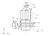
Classifications
-
- G—PHYSICS
- G02—OPTICS
- G02B—OPTICAL ELEMENTS, SYSTEMS OR APPARATUS
- G02B7/00—Mountings, adjusting means, or light-tight connections, for optical elements
- G02B7/02—Mountings, adjusting means, or light-tight connections, for optical elements for lenses
- G02B7/04—Mountings, adjusting means, or light-tight connections, for optical elements for lenses with mechanism for focusing or varying magnification
- G02B7/06—Focusing binocular pairs
-
- G—PHYSICS
- G02—OPTICS
- G02B—OPTICAL ELEMENTS, SYSTEMS OR APPARATUS
- G02B23/00—Telescopes, e.g. binoculars; Periscopes; Instruments for viewing the inside of hollow bodies; Viewfinders; Optical aiming or sighting devices
- G02B23/16—Housings; Caps; Mountings; Supports, e.g. with counterweight
- G02B23/18—Housings; Caps; Mountings; Supports, e.g. with counterweight for binocular arrangements
-
- G—PHYSICS
- G02—OPTICS
- G02B—OPTICAL ELEMENTS, SYSTEMS OR APPARATUS
- G02B27/00—Optical systems or apparatus not provided for by any of the groups G02B1/00 - G02B26/00, G02B30/00
- G02B27/64—Imaging systems using optical elements for stabilisation of the lateral and angular position of the image
- G02B27/646—Imaging systems using optical elements for stabilisation of the lateral and angular position of the image compensating for small deviations, e.g. due to vibration or shake
-
- G—PHYSICS
- G02—OPTICS
- G02B—OPTICAL ELEMENTS, SYSTEMS OR APPARATUS
- G02B25/00—Eyepieces; Magnifying glasses
- G02B25/002—Magnifying glasses
- G02B25/004—Magnifying glasses having binocular arrangement
Definitions
- the present invention relates to binoculars and their operation switches.
- an optical observation apparatus for enlarging and observing an optical image of a distant view
- a binocular equipped with a pair of telephoto optical systems arranged in the left-right direction.
- an optical observation apparatus including an image stabilizer for correcting image shake of an optical image in order to prevent image shake of the optical image due to vibration such as camera shake is also known.
- the anti-vibration device moves the optical member in a direction that suppresses touching of the image to prevent vibration, and a driving member such as a voice coil motor is used. Then, when operating the image stabilization operation, the operation switch is turned ON.
- a lock member is provided, and this lock member is moved between a lock position for locking the operation of the image blur prevention means and an unlock position for releasing the lock. .
- the operation switch of the image blur prevention means is switched between ON and OFF by the movement of the lock member.
- the anti-vibration switch when operating the anti-vibration switch, is placed at the center of the binoculars so that the fingers can reach from either side to make it possible to operate from both right-handed and left-handed. It is preferable.
- an anti-vibration switch is arranged at the center of the binoculars.
- an object of the present invention is to provide a binocular that can be easily operated even with the left or right hand and its operation switch.
- the binoculars of the present invention include two lens barrels, an operation member, a plurality of finger hooks, an urging member, a receiving member, and a switch body.
- the operation member is disposed between the two lens barrels so as to be swingable.
- the finger-hanging portion protrudes from the operation member toward the two lens barrels.
- the urging member urges the operation member in a state where at least two finger-hanging portions have the same inclination angle with respect to the two lens barrels.
- the receiving member is pushed by the rotation of the operation member in one direction and the rotation in the other direction by the swinging operation to the finger hanging portion against the urging of the urging member.
- the switch body is opened and closed by the pressing of the receiving member.
- the receiving member has a first receiving surface and a second receiving surface, and the switch body is closed from open to closed by pushing to the first receiving surface and the second receiving surface.
- the first receiving surface is pushed by rotational displacement in one direction by the operation member.
- the second receiving surface is pushed by the rotational displacement in the other direction by the operation member.
- the swing lever includes a first contact portion and a second contact portion.
- the first abutting portion pushes the first receiving surface by rotational displacement in one direction of the operation member.
- the second contact portion pushes the second receiving surface by rotational displacement of the operation member in the other direction.
- an intermediate lever is provided between the operation member and the swing lever, and that the intermediate lever has one end held by the operation member and the other end engaged with the swing lever.
- the operation member is rotatably attached to a focus adjustment shaft that is rotated to adjust the focus of the lens barrel.
- an anti-vibration device and an anti-vibration regulating member corrects image blur of the optical image by displacing at least a part of the optical members in the lens barrel.
- the anti-vibration regulating member is between the anti-vibration regulating position that contacts the anti-vibration member of the anti-vibration device and restricts the movement of the anti-vibration member and the anti-vibration position that allows the movement of the anti-vibration member away from the anti-vibration member Displace at.
- the position of the image stabilization regulating member is switched between the image stabilization regulation position state and the image stabilization position state, and image stabilization control is performed.
- the receiving member has a first engaging portion
- the anti-vibration regulating member has a second engaging portion that engages with the first engaging portion.
- the anti-vibration member is preferably a first link member that corrects image blur in the yaw direction and a second link member that corrects image blur in the pitch direction.
- the anti-vibration restricting member has a first restricting member and a second restricting member. The first restricting member is engaged with the first engaging hole of the first link member in the state of the vibration isolation position to restrict the movement of the first link member. The second restricting member is engaged with the second engaging hole of the second link member in the state of the vibration proof position to restrict the movement of the second link member.
- the vibration isolator preferably includes a first reflecting member, a second reflecting member, and a holding member.
- the first reflecting member is inclined with respect to the first optical axis, and deflects the first optical axis to be the second optical axis.
- the second reflecting member is disposed to be inclined with respect to the second optical axis, and deflects the second optical axis to be a third optical axis parallel to the first optical axis.
- the holding member holds the first reflecting member and the second reflecting member, is in a plane including the first optical axis and the second optical axis, and has a first rotation axis that intersects the first optical axis or the third optical axis. It is arranged so as to be rotatable around.
- the holding member fixes and holds one of the first reflecting member and the second reflecting member, and rotates the other around a second rotation axis perpendicular to a plane including the first optical axis and the second optical axis. Hold freely.
- the first link member rotates a pair of holding members arranged in a state where the first optical axes are held in parallel with the first rotation shaft.
- the second link member is attached to the first link member so as to be rotatable around a third rotation axis parallel to the second rotation axis, and the other of the first reflection member and the second reflection member is attached to the second link member. It rotates on the moving shaft.
- the first voice coil motor moves the first link member in a first direction that is an arrangement direction of the holding members.
- the second voice coil motor rotates the second link member around a third rotation axis by moving the second link member in a second direction orthogonal to the first direction.
- the operation switch of the binoculars of the present invention includes an operation member, a plurality of finger hooks, an urging member, a receiving member, and a switch body.
- the operating member is swingably disposed between the two lens barrels of the binoculars.
- the finger-hanging portion protrudes from the operation member toward the two lens barrels.
- the urging member urges the operation member in a state in which at least two finger hooks have the same inclination angle with respect to the two lens barrels.
- the receiving member is pushed by the rotation of the operation member in one direction and the rotation in the other direction by the swinging operation to the finger hanging portion against the urging of the urging member.
- the switch body is opened and closed by the pressing of the receiving member.
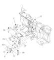
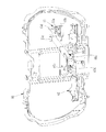
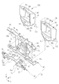
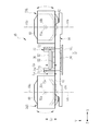
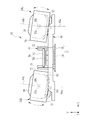
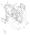
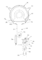
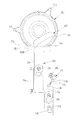
- FIG. 10 is a side view showing the swing lever and the receiving member in a state where the operation dial is rotated in a direction different from that in FIG. 9. It is a perspective view which shows the engagement hole by the side of the link member which each regulation pin of a vibration proof regulation lever engages. It is a perspective view which shows the structure of a vibration isolator. It is a disassembled perspective view of the left side vibration proof unit containing a vibration proof optical system. It is a disassembled perspective view of a link mechanism. It is a perspective view which shows the edge part shape of a 2nd link member.
- FIG. 10 is a front view showing a second embodiment in which a swing lever is directly swung by operation of an operation dial and a receiving member is in a neutral position. It is a front view which shows the state of a receiving member in a pushing position.
- the binoculars 30 of this embodiment are for observing an optical image of a distant view enlarged by a pair of left and right telephoto optical systems 37L and 37R configured by a telephoto optical system.
- an optical observation device used for The binoculars 30 are provided with a vibration isolator 45 (see FIG. 2) described later.
- the vibration isolator 45 has a pitch around the X axis when the front and rear direction of the binoculars 30 is the Y axis, the width direction orthogonal to the front and rear direction is the X axis, and the Y axis and the vertical axis orthogonal to the X axis are the Z axis.
- the image blur in the direction and the image blur in the yaw direction around the Z axis are corrected.
- the binoculars 30 include a main body 31, a pair of left and right eyepieces 33L, and a right eyepiece 33R.
- the front surface 31a of the main body 31 is provided with a pair of left and right objective openings 32L and 32R.
- the left eyepiece 33L and the right eyepiece 33R are provided on the back side of the main body 31.
- the binoculars 30 hold the main body 31, direct the left objective opening 32L and the right objective opening 32R toward the object to be observed, and look into the left eyepiece part 33L and the right eyepiece part 33R with both eyes. An enlarged image can be observed.
- a left objective optical system 35L and a right objective optical system 35R are provided behind the left objective aperture 32L and the right objective aperture 32R.
- the left objective optical system 35L and the right objective optical system 35R are arranged with a pair of left and right optical axes 64a (see FIG. 2 etc.) arranged in parallel.
- the left eyepiece optical system 36L and the right eyepiece optical system 36R are provided inside the left eyepiece 33L and the right eyepiece 33R.
- the left objective optical system 35L, the right objective optical system 35R, the left eyepiece optical system 36L, and the right eyepiece optical system 36R are each composed of a lens having a positive composite focal length. Note that the left objective optical system 35L, the right objective optical system 35R, the left eyepiece optical system 36L, and the right eyepiece optical system 36R are each illustrated as a single lens in order to prevent the drawing from becoming complicated, but a plurality of lenses are provided. You may comprise with the lens of.
- the left objective optical system 35L and the left eyepiece optical system 36L are disposed on the left-eye optical axis BL set along the front-rear direction (Y-axis direction) of the binoculars 30, and constitute the left telephoto optical system 37L. To do. Further, the right objective optical system 35R and the right eyepiece optical system 36R have a right-eye optical axis BR set in parallel with the left-eye optical axis BL in the width direction (X-axis direction) orthogonal to the front-back direction of the binoculars 30. The right telephoto optical system 37R is disposed above. In the following, in the Y-axis direction, the objective side is the front and front ends, and the eyepiece side is the rear and rear ends.
- a battery housing chamber 39 (see FIG. 2) is provided inside the main body 31.
- a battery 42 serving as a power source for a first voice coil motor 56 and a second voice coil motor 57 (see FIGS. 2, 20, and 21) and an image stabilization control circuit 91 (see FIG. 22), which will be described later, are provided in the battery housing 39. (See FIG. 2) is housed.
- the battery 42 is configured in a rectangular plate shape.
- a focus adjustment knob 40 that is rotated when performing focus adjustment is provided on the upper rear side of the main body 31.
- the power switch (operation switch) 10 (see also FIG. 4) of the present invention is provided on the same axis as the focus adjustment knob 40.
- the power switch 10 activates the image stabilization control circuit 91 during a turning operation.
- the binocular 30 includes a housing 43, a left objective barrel 44L, a right objective barrel 44R, a vibration isolator 45, a control board 46, a left erecting optical system 47L, and a right erecting optical system.
- a system 47R, a left eyepiece tube 48L, and a right eyepiece tube 48R are provided.
- the anti-vibration device 45 including the anti-vibration optical system and the left erecting optical system 47L are included in the left telephoto optical system 37L.
- the vibration isolator 45 and the right erecting optical system 47R are included in the right telephoto optical system 37R.
- the housing 43 includes a housing body 50, a left eyepiece housing 51L, and a right eyepiece housing 51R.
- the housing body 50 is an exterior of the body portion 31.
- the left eyepiece housing 51L is an exterior of the left eyepiece 33L.
- the right eyepiece housing 51R is an exterior of the right eyepiece 33R.
- the housing body 50 accommodates a left objective lens barrel 44L, a right objective lens barrel 44R, a vibration isolator 45, and a control board 46.
- the left eyepiece housing 51L houses a left erecting optical system 47L and a left eyepiece tube 48L.
- the right eyepiece housing 51R houses a right erecting optical system 47R and a right eyepiece tube 48R.
- a support member 53 is fixed to the housing body 50.
- the support member 53 supports the vibration isolator 45 from above and below.
- the left eyepiece case 51L and the right eyepiece case 51R are respectively provided with a left eyepiece opening 52L and a right eyepiece opening 52R in order to expose the left eyepiece optical system 36L and the right eyepiece optical system 36R to the outside. Further, the left eyepiece case 51L and the right eyepiece case 51R are fitted so as to be rotatable with respect to the central axis along the Y-axis direction of the case body 50, respectively. Thereby, the width of the left eyepiece optical system 36L and the right eyepiece optical system 36R in the X-axis direction can be adjusted in accordance with the distance between both eyes of the binoculars user.
- the left objective barrel 44L and the right objective barrel 44R have a cylindrical shape, and accommodate the left objective optical system 35L and the right objective optical system 35R, respectively.
- the left objective barrel 44L and the right objective barrel 44R are held so as to be movable in the direction of the optical axis 64a by a holding mechanism (not shown).
- the holding mechanism moves the left objective barrel 44L and the right objective barrel 44R in the direction of the optical axis 64a by rotating the focus adjustment knob 40.
- FIG. 4 is a perspective view showing the overall configuration of the power switch 10.
- the power switch 10 includes an operation dial 11 as an operation member, an interlocking mechanism 12, a receiving member 13, a switch main body 14, and an anti-vibration restriction lever 15 as an anti-vibration restriction member.
- the operation dial 11 is rotatably attached to a focus adjustment shaft 16 to which a focus adjustment knob 40 is fixed at one end.
- the focus adjustment shaft 16 is rotatably attached to a support member 53 (see FIG. 8) by an attachment shaft portion 17.
- a male screw portion 16a is formed at the other end of the focus adjustment shaft 16, and a moving bracket 18 is screwed into the male screw portion 16a.
- the moving bracket 18 is attached so as not to rotate with respect to the circumferential direction of the focus adjustment shaft 16 and to be movable in the axial direction of the focus adjustment shaft 16.
- the moving bracket 18 is linked to the left objective barrel 44L and the right objective barrel 44R (see FIG. 2). Accordingly, when the focus adjustment shaft 16 is rotated by the rotation operation of the focus adjustment knob 40, the left objective lens barrel 44L and the right objective lens barrel 44R are moved in the optical axis direction via the moving bracket 18, and the focus is adjusted. .
- the finger dial 11a protrudes from the outer peripheral surface of the operation dial 11.
- two finger hooks 11 a are provided at intervals of 120 degrees in the outer peripheral direction of the operation dial 11.
- the operation dial 11 is formed in a hollow double cylinder shape in which a mounting cylinder 11b and an outer cylinder 11c are connected by a disk portion 11d.
- the interlocking mechanism 12 is a mechanism that converts a rotational displacement into a pushing displacement of the member 13 by a rotational operation by the finger hooking portion 11a of the operation dial 11.
- the interlocking mechanism 12 includes a torsion coil spring 19, an intermediate lever 21, and a swing lever 25 (see FIG. 4).
- a torsion coil spring 19 is attached to the outer peripheral surface of the mounting cylinder 11b of the operation dial 11.
- the torsion coil spring 19 urges the operation dial 11 to return to the neutral position when the operation dial 11 is swung by the finger hooking on the finger hooking portion 11a.
- the neutral position is a position where the finger hook portion 11a is line symmetric with respect to a vertical line passing through the central axis of the focus adjustment shaft 16. In this neutral position, the finger hook portion 11a has the same inclination angle with respect to the left objective lens barrel 44L and the right objective lens barrel 44R, and the left eyepiece tube 48L and the right eyepiece tube 48R.
- a locking hole 11e is formed in the disk portion 11d between the mounting cylinder 11b and the outer cylinder 11c of the operation dial 11.
- One end 21a of the intermediate lever 21 is locked in the locking hole 11e.
- the intermediate lever 21 is attached by an intermediate lever holding member 22 so as to be swingable in the vertical direction with its central portion as a fulcrum.
- a rubber holding bracket 24 is attached to the shaft portion of the intermediate lever 21 on the side of the locking hole 11e.
- the holding bracket 24 has a plurality of concentric grooves in the circumferential direction, and horizontally holds the intermediate lever 21 by its own elasticity when the operation dial 11 is in the neutral position.
- An engagement pin 21c is formed on the other end 21b of the intermediate lever 21 so as to protrude in the horizontal direction. The engagement pin 21c engages with an engagement hole 25d at one end of the swing lever 25 shown in FIG. 6, and the swing lever 25 swings as the intermediate lever 21 swings.
- the swing lever 25 is rotatably supported by the mounting shaft 25a. As shown in FIG. 4, when the operation dial 11 is in the neutral position, the swing lever 25 is in a horizontal state, and the first contact portion 25b and the second contact portion 25c are at the same horizontal level.
- a receiving member 13 that contacts the first contact portion 25b and the second contact portion 25c of the swing lever 25 is provided below the swing lever 25.
- the receiving member 13 is formed long in the vertical direction, and is attached to the support member 53 so as to be slidable in the vertical direction by means of mounting screws 13a.
- the receiving member 13 is integrally formed by connecting a T-shaped receiving portion 13b and two slider main bodies 13c and 13d in the vertical direction.
- a step portion 13e is formed at the connecting portion of the two slider main bodies 13c and 13d by shifting both the portions 13c and 13d in the horizontal direction.
- a spring locking portion 13f is formed on one side of the slider body 13c.
- One end of the first coil spring 26a is locked to the spring locking portion 13f.
- the other end of the first coil spring 26a is engaged with the support member 53, and the receiving member 13 is urged upward in the vertical direction by the first coil spring 26a.
- the receiving member 13 is maintained in the neutral state moved upward.
- the first contact portion 25b of the swing lever 25 contacts the first receiving surface 13g of the receiver portion 13b
- the second contact portion 25c of the swing lever contacts the second receiving surface 13h.
- a switch body 14 is arranged near the step 13e.
- the switch body 14 is fixed to the support member 53 by mounting screws 14a.
- the switch body 14 includes a first switch piece 14b, a second switch piece 14c, and an engagement piece 14d having different lengths.
- the first switch piece 14b and the second switch piece 14c are arranged to face each other.
- a block-shaped engagement piece 14d is attached to the tip of the longer first switch piece 14b.
- the stepped portion 13e pushes the engaging piece 14d.
- the switch body 14 is open.
- an engagement hole 13k as a first engagement portion is formed in the lower end portion of the receiving member 13.
- an engagement pin (second engagement portion) 15a of the anti-vibration control lever 15 is inserted in the assembled state.
- the anti-vibration regulation lever 15 is attached to the support member 53 so as to be swingable by an attachment shaft 15b extending in the horizontal direction.
- the anti-vibration regulating lever 15 is formed with a spring locking portion 15c protruding therefrom.
- One end of the second coil spring 26b is locked to the spring locking portion 15c.
- the other end of the second coil spring 26 b is locked to the support member 53.
- the anti-vibration regulating lever 15 is biased by the second coil spring 26b so as to face in the vertical direction.
- the anti-vibration restriction lever 15 is formed with a first restriction pin 15d as a first restriction member and a second restriction pin 15e as a second restriction member protruding from the upper part.
- the anti-vibration regulating lever 15 swings by the engagement pin 15a being pressed downward by the engagement hole 13k.
- the anti-vibration regulating lever 15 is released from the anti-vibration restricting position in the locked state shown in FIGS. 6 and 7, as shown in FIGS. 9 and 10. It is displaced between the vibration-proof position of the state.
- the first restricting pin 15d of the anti-vibration restricting lever 15 enters the first engagement hole 66c of the first link member 66 as the anti-vibration member shown in FIG.
- the movement of 66 in the horizontal direction (first direction) is restricted.
- the second restriction pin 15e of the anti-vibration restriction lever 15 enters the second engagement hole 67b of the second link member 67 as the anti-vibration member, and the second link member 67 in the vertical direction (second Direction).
- These pins 15d and 15e restrict the movement of the first link member 66 and the second link member 67 of the vibration isolator 45.
- the switch body 14 When the receiving member 13 is pushed down by the swing of the swing lever 25, the switch body 14 is closed and the vibration control circuit 91 is turned on. Further, when the image stabilization control lever 15 changes from the image stabilization control position to the image stabilization position, the image stabilization control circuit 91 is turned on, and thus image stabilization control is possible.
- the first engagement hole 66c has a guide surface 66d that gradually expands in the horizontal direction.
- the second engagement hole 67b has a guide surface 67c that gradually expands in the vertical direction.
- the first restricting pin 15d has a guide surface with a tapered tip.
- the second restriction pin 15e has a cylindrical shape, and this outer peripheral surface functions as a guide surface.
- the operation dial 11 When the turning operation by the finger hanging portion 11a of the operation dial 11 is stopped and the finger is released from the finger hanging portion 11a or the force is relaxed, the operation dial 11 returns to the neutral position.
- the receiving member 13 When the operation dial 11 returns to the neutral position, the receiving member 13 is not pushed by the interlocking mechanism 12. Since the receiving member 13 is biased upward by the first coil spring 26a, when the pushing of the receiving member 13 stops, the receiving member 13 moves upward and returns to the neutral position.
- the anti-vibration regulating lever 15 interlocked via the engaging pin 15a and the engaging hole 13k is moved from the anti-vibration position to the anti-vibration restriction position. become.
- the regulation pins 15d and 15e are guided by the guide surfaces 66d and 67c, so that the regulation pins 15d and 15e can be smoothly and quickly engaged with the engagement holes 66c and 67b.
- the first link members 66 and 67 can be returned to the neutral position.
- the restricting pins 15d and 15e can be returned to the engaging holes 66c and 67b.
- the upward movement of the receiving member 13 also eliminates the pushing to the engaging piece 14d by the step 13e, and the switch body 14 is opened.
- the image stabilizer 45 is a device for correcting image blur caused in an optical image due to camera shake or the like.
- the image stabilizer 45 is disposed between the left objective optical system 35L and the right objective optical system 35R, and the left eyepiece optical system 36L and right eyepiece optical system 36R.
- the vibration isolator 45 includes a left vibration isolation unit 54L, a right vibration isolation unit 54R, a link mechanism 55, a first voice coil motor 56, and a second voice coil motor 57.
- the left image stabilization unit 54L is a mechanism that corrects image blur in the left telephoto optical system 37L.
- the left image stabilization unit 54L is disposed between the left objective optical system 35L and the left eyepiece optical system 36L, and constitutes a part of the left telephoto optical system 37L.
- the right image stabilization unit 54R is a mechanism that corrects image blur in the right telephoto optical system 37R.
- the right image stabilization unit 54R is disposed between the right objective optical system 35R and the right eyepiece optical system 36R, and constitutes a part of the right telephoto optical system 37R.
- the link mechanism 55 is a mechanism for connecting the left image stabilization unit 54L and the right image stabilization unit 54R to cause the left image stabilization unit 54L and the right image stabilization unit 54R to perform the same operation during image blur correction.
- the first voice coil motor 56 and the second voice coil motor 57 are disposed between the left vibration isolation unit 54L and the right vibration isolation unit 54R, and by driving the link mechanism 55, the left vibration isolation unit 54L and the right vibration isolation unit 54R.
- the vibration unit 54R is caused to perform the same operation.
- the left erecting optical system 47L and the right erecting optical system 47R invert the top, bottom, left and right of the optical image whose image blur has been corrected by the image stabilizer 45, and enter the left eyepiece optical system 36L and the right eyepiece optical system 36R. It is an optical system.
- erecting prisms such as Porro prisms and roof prisms are used, for example.
- the left eyepiece tube 48L and the right eyepiece tube 48R have a cylindrical shape, and accommodate the left eyepiece optical system 36L and the right eyepiece optical system 36R, respectively.
- the left vibration isolation unit 54 ⁇ / b> L includes a lens frame 59, a first reflecting member 60, a holding plate 61, and a second reflecting member 62.
- the lens frame 59 has a box shape in which the front side and the back side are opened.
- the first reflecting member 60 is fixed in the lens frame 59.
- the holding plate 61 is rotatably supported in the lens frame 59.
- the second reflecting member 62 is fixed to the upper surface of the holding plate 61.
- a surface reflection type reflection mirror is used for the first reflection member 60 and the second reflection member 62.
- the lens frame 59 corresponds to the holding member of the present invention.
- the first reflecting member 60 and the second reflecting member 62 correspond to at least a part of the optical members in the lens barrel.
- the first reflecting member 60 is inserted into the lens frame 59 and fixed to the upper surface of the inner wall of the lens frame 59 with an adhesive or the like so that the reflecting surface faces downward.
- the upper surface of the inner wall of the lens frame 59 as viewed from the X-axis direction is inclined at an angle of 45 ° with respect to the first optical axis 64a that is the optical axis of the left objective optical system 35L. Yes.
- the first reflecting member 60 fixed in the lens frame 59 is also held at an angle of 45 ° with respect to the first optical axis 64a.
- the holding plate 61 is a rectangular plate member.
- a second reflecting member 62 is fixed to the upper surface of the holding plate 61 with an adhesive or the like so that the reflecting surface faces upward.
- a pair of rotation pins 61 a are provided on both side surfaces of the holding plate 61.
- the pair of rotation pins 61a are inserted into a pair of bearing holes 59a provided on both side surfaces of the lens frame 59.
- the pair of rotation pins 61a supported by the pair of bearing holes 59a constitute the second rotation shaft 112 of the present invention.
- the lower surface of the holding plate 61 is provided with a bracket 61b protruding downward.
- a connecting pin 61c protruding in the Y-axis direction is provided at the tip of the bracket 61b.
- the holding plate 61 is rotated by the link mechanism 55 via the connecting pin 61c.
- the holding plate 61 is linked so that the second reflecting member 62 is parallel to the first reflecting member 60 in a state where the binoculars 30 are not shaken (neutral state: the state shown in FIGS. 16 and 18). The angle is maintained by the mechanism 55.
- a pair of bearing bosses 59b are provided on the same Z-axis on the upper and lower surfaces of the lens frame 59.
- the bearing boss 59b is rotatably supported by a pair of bearing pins 53a (see FIG. 3) erected on the inner wall upper surface and the inner wall lower surface of the support member 53.
- the bearing pin 53a supported by the pair of bearing bosses 59b functions as the first rotating shaft 111 (see FIGS. 13 and 14) of the present invention.
- a pair of upper connecting boss 59c and lower connecting boss 59d are provided on the same Z-axis at the upper and lower portions on the front side of the lens frame 59.
- the pair of upper connection boss 59 c and lower connection boss 59 d is used for connection with the link mechanism 55.
- the first reflecting member 60 deflects the first optical axis 64a of the left objective optical system 35L by reflection, and a second optical axis 64b (see FIG. 3, FIG. 12, etc.) perpendicular to the first optical axis 64a. To do.
- the second optical axis 64b is parallel to the Z-axis direction.
- the second reflecting member 62 deflects the second optical axis 64b by reflection to obtain a third optical axis 64c (see FIGS. 3 and 12, etc.) parallel to the first optical axis 64a.
- the first optical axis 64a and the third optical axis 64c are parallel to the Y-axis direction.
- the rotation pin 61a of the holding plate 61 passes through the intersection of the reflection surface of the second reflection member 62 and the second optical axis 64b, and is a second perpendicular to the plane formed by the first optical axis 64a and the second optical axis 64b. It functions as the rotating shaft 112. Accordingly, the second reflecting member 62 can change the deflection direction of the third optical axis 64c and correct the image blur in the pitch direction by rotating around the rotation pin 61a.
- the bearing boss 59 b of the lens frame 59 is provided concentrically with the second optical axis 64 b coincident with the central axis, and functions as the first rotating shaft 111. Accordingly, the first reflecting member 60 and the second reflecting member 62 are integrated and rotate around the bearing boss 59b to change the deflection direction of the third optical axis 64c, thereby correcting the image blur in the yaw direction. Can do.
- the first rotation axis 111 is in a plane including the first optical axis 64a and the third optical axis 64c and intersects the first optical axis 64a or the third optical axis 64c.
- the right vibration isolation unit 54R has the same configuration as the left vibration isolation unit 54L, and is supported by the housing body 50 so as to be rotatable around the Z-axis in the same manner as the left vibration isolation unit 54L.
- the right vibration isolation unit 54R is connected to the link mechanism 55 with the same structure as the left vibration isolation unit 54L. Therefore, detailed description of the right vibration isolation unit 54R is omitted.
- the link mechanism 55 includes a first link member 66 and a second link member 67.
- the first link member 66 connects the lens frames 59 of the left vibration isolation unit 54L and the right vibration isolation unit 54R.
- the pair of left and right lens frames 59 connected by the first link member 66 are arranged in a state where the first optical axes 64a are held in parallel.
- a pair of left and right lens frames 59 are connected by a first link member 66, whereby a frame upper plate having a bearing boss 59b and an upper connecting boss 59c of the lens frame 59, and a bearing boss 59b and a lower portion of the lens frame 59 are also provided.
- the frame lower plate having the connecting boss 59d functions as an intermediate link.
- These intermediate links constitute a four-joint link portion that horizontally moves the first link member 66 in the X-axis direction.
- the second link member 67 connects the left and right pair of second reflection members 62 held by the left vibration isolation unit 54L and the right vibration isolation unit 54R.
- the second link member 67 is rotatably supported by the first link member 66.
- the first link member 66 includes a first bracket 69, a second bracket 70, and a pair of connecting portions 71.
- a pair of right and left connecting pins 69a to be inserted into the upper connecting boss 59c of the lens frame 59 is provided.
- a pair of left and right connecting pins 70a to be inserted into the lower connecting boss 59d of the lens frame 59 are provided.
- the pair of connecting portions 71 are arranged in the vertical direction so that the first bracket 69 and the second bracket 70 are integrated.
- the pair of connecting portions 71 are provided with a pair of left and right third brackets 72 (see also FIGS. 16 and 17) between the lens frames 59.
- the third bracket 72 protrudes toward the eyepiece optical systems 36L and 36R in the Y-axis direction.
- the third bracket 72 is provided with a connecting hole 72a on the same X axis.
- the pair of connecting portions 71 are provided with notches 71a on the side opposite to the side where the third bracket 72 is provided.
- the second link member 67 is accommodated in the notch 71a.
- the second link member 67 includes a rod-shaped link body 74 and a pair of left and right connecting arms 75.
- the link main body 74 extends in the X-axis direction.
- the link body 74 is provided with a pair of left and right connecting arms 75 between the lens frames 59.
- the connecting arm 75 protrudes toward the eyepiece optical systems 36L and 36R in the Y-axis direction.
- the connecting arm 75 is provided in the vicinity of the third bracket 72 inside the third bracket 72 (see FIGS. 16 and 17).
- a connecting pin 75 a is provided on the side surface of the connecting arm 75.
- the connection pin 75 a is inserted into a connection hole 72 a provided in the third bracket 72 of the first link member 66.
- the connection pin 75a supported by the connection hole 72a constitutes the third rotation shaft 113 (see FIG. 21) of the present invention.
- the second link member 67 is configured so that the second link member 67 is rotatable around the third rotation shaft 113 when the connection arm 75 and the third bracket 72 constituting the third rotation shaft 113 are connected. It is supported by one link member 66.
- a contact portion 77 is provided at each end of the link body 74.
- the contact portion 77 contacts the connecting pin 61c of the holding plate 61 from below.
- the contact surface 77a of the contact portion 77 is formed of a convex circumferential surface.
- the contact surface 77a and the connection pin 61c come into contact with each other on the circumferential surface, so that the contact portion 77 and the connection pin 61c are in point contact even when the second link member 67 is rotated, and between the centers of the two. The distance will not change. Therefore, the rotation of the second link member 67 can be smoothly transmitted to the connecting pin 61c.
- a pair of urging members 78 are attached to both ends of the link body 74.
- the urging member 78 urges the connecting pin 61 c of the holding plate 61 to abut against the abutting portion 77.
- As the urging member 78 for example, a torsion coil spring or a leaf spring made of metal is used.
- the urging member 78 urges the connecting pin 61 c and the abutting portion 77 comes into contact with the connecting pin 61 c, the link main body 74 engages with the pair of left and right second reflecting members 62 via the holding plate 61. To do.
- the link mechanism 55 moves the first link member 66 in the X-axis direction to move the lens frame 59 of the left vibration isolation unit 54L and the right vibration isolation unit 54R to the bearing boss 59b.
- the first rotation axis 111 parallel to the Z axis.
- the first reflection member 60 and the second reflection member 62 of the left vibration isolation unit 54L and the right vibration isolation unit 54R rotate together, so that the deflection direction of the third optical axis 64c is changed and the yaw direction is changed. Image blur is corrected.
- the length of the third bracket 72 of the first link member 66 in the Y-axis direction (the length from the connection pin 69a to the connection hole 72a) La and the second link member in the same direction
- the length Lb of the connecting arm 75 (the length from the center of the link main body 74 to the connecting pin 75a) Lb is the same as the length Lc from the upper connecting boss 59c of the lens frame 59 to the bearing boss 59b.
- the height in the Z-axis direction is the same.
- the 2nd rotating shaft 112 and the 3rd rotating shaft 113 are arrange
- the length Lc which is a turning radius when the vibration isolator unit 54 is turned by the first link member 66, and the turning radius when the second reflecting member 62 is turned by the second link member 67. Since the lengths Lb and Lc are the same, the second link member 67 can be rotated even when the vibration isolation unit 54 is rotated around the first rotation shaft 111 and tilted. .
- the first voice coil motor 56 and the second voice coil motor 57 together with the detection magnet 88 and the Z-axis position sensor 89 (see FIG. 21) constitute the drive device 58 (see FIG. 23) of the present embodiment.
- the first voice coil motor 56 and the second voice coil motor 57 are located at the center of the left telephoto optical system 37L and the right telephoto optical system 37R.
- the center of the left telephoto optical system 37L and the right telephoto optical system 37R is sandwiched between the left telephoto optical system 37L and the right telephoto optical system 37R in the X-axis direction, and the left objective optical system 35L and the right objective in the Y-axis direction.
- the first voice coil motor 56 includes a first coil 80, a first driving magnet 81, and yokes 82A and 82B.
- the first coil 80 is formed by winding a copper wire or the like, is a cylindrical air core coil having a substantially rectangular cross section, and is attached to the attachment portion 66 a of the first link member 66.
- the yokes 82 ⁇ / b> A and 82 ⁇ / b> B are formed of a metal plate, and are arranged at positions where the first coil 80 and the first driving magnet 81 are sandwiched, and guide the magnetism of the first driving magnet 81 to the first coil 80.
- the yoke 82 ⁇ / b> B has a U-shaped cross section that covers the back surface and both side surfaces of the first driving magnet 81, and is fixed to the housing body 50.
- the yoke 82B is attracted to the first drive magnet 81 by the magnetic force of the first drive magnet 81.
- the yoke 82A is fixed integrally with the yoke 82B and covers the front side of the first drive magnet 81.
- the first coil 80 is disposed between the yoke 82 ⁇ / b> A and the first driving magnet 81, and is movable in a magnetic field generated by the first driving magnet 81.
- the first voice coil motor 56 is a so-called flat coil type voice coil motor (Voice Coil Motor), and the first coil 80 in the magnetic field of the first drive magnet 81 is caused to flow through the first coil 80. Moves in the X-axis direction and drives the first link member 66. By driving the first voice coil motor 56, the first link member 66 moves along the X-axis direction.
- a detection magnet 83 is embedded in the upper surface of the first bracket 69.
- an X-axis position sensor 84 is provided on the upper surface of the inner wall of the housing body 50.
- the X-axis position sensor 84 is disposed at a position facing the detection magnet 83 and measures the amount of movement of the first link member 66 including the first coil 80 in the X-axis direction.
- the X-axis position sensor 84 is a magnetic sensor such as a Hall element, for example, detects the magnetism of the detection magnet 83, and outputs a detection signal corresponding to the strength of the magnetism.
- the second voice coil motor 57 includes a second coil 85, a second drive magnet 86, and a yoke 87.
- the second coil 85 is a cylindrical air-core coil formed from a copper wire or the like, similar to the first coil 80, and is attached to a pair of attachment portions 67 a of the second link member 67.
- the link body 74 has a notch 74a in the center.
- the second drive magnet 86 is disposed inside the notch 74a.
- the pair of attachment portions 67a are formed to protrude forward from the notches 74a. For this reason, the second drive magnet 86 is disposed on the back side of the second coil 85.
- the yoke 87 is formed of a metal plate, and is disposed at a position sandwiching the second coil 85 and the second drive magnet 86, and guides the magnetism of the second drive magnet 86 to the second coil 85.
- the yoke 87 is formed in a U-shaped cross section that covers the front and back surfaces of the second drive magnet 86, and is fixed to the yoke 82A of the first voice coil motor 56 via a connecting member (not shown).
- the yoke 87 is attracted to the second driving magnet 86 by the magnetic force of the second driving magnet 86.
- the second coil 85 is disposed between the yoke 87 and the second drive magnet 86 and is movable within a magnetic field generated by the second drive magnet 86.
- the second voice coil motor 57 is a voice coil motor similar to the first voice coil motor 56, and the second coil 85 is caused to flow in the magnetic field of the second drive magnet 86 by passing a current through the second coil 85.
- the second link member 67 is driven by moving in the Z-axis direction. By driving the second voice coil motor 57, the second link member 67 rotates around the third rotation shaft 113.
- the link body 74 has a holding portion 74b.
- a detection magnet 88 is embedded in the holding portion 74b. That is, the detection magnet 88 moves integrally with the second link member 67.
- the holding portion 74b is disposed on the side where the right vibration isolation unit 54R is positioned with respect to the notch 74a.
- a Z-axis position sensor 89 is attached to the first link member 66 via a holding piece 66b.
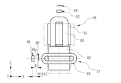
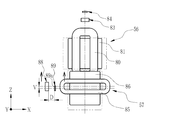
- the Z-axis position sensor 89 is arranged at a position where the detection surface 89a (see FIGS. 23, 24A to 24D) faces the detection magnet 88, and the Z-axis direction of the second link member 67 including the second coil 85 Measure the amount of movement.
- the Z-axis position sensor 89 is a magnetic sensor similar to the X-axis position sensor 84, detects the magnetism of the detection magnet 88, and outputs a detection signal corresponding to the strength of the magnetism.
- the holding piece 66b has a rectangular frame shape covering the periphery of the Z-axis position sensor 89.
- the holding piece 66b is fastened to the first link member 66 via a coupling screw 90, and is separated from the second coil 85 in the X-axis direction, and between the attachment portion 67a and the holding portion 74b.
- the Z-axis position sensor 89 is held at the sandwiched position.
- the detection magnet 88 is arranged on the side opposite to the second coil 85 with respect to the Z-axis position sensor 89 in the X-axis direction, that is, on the side where the right vibration isolation unit 54R is located.
- the holding piece 66b has rigidity, and holds the Z-axis position sensor 89 with a predetermined distance D (see FIGS. 24A to 24D) with respect to the detection magnet 88 in the X-axis direction.
- a predetermined distance D is preferably 50% to 200% of the movement stroke HMAX.
- the image stabilization control circuit 91 provided on the control board 46 includes a ROM (Read Only Memory) 92, a CPU (Central Processing Unit) 93, a shake amount measuring sensor 94, a driver 95, 96.
- the ROM 92 stores a control program.
- the CPU 93 controls the image stabilizer 45 based on the control program.
- the shake amount measuring sensor 94 measures the shake amount of the binoculars 30 around the X axis and the Z axis.
- the drivers 95 and 96 drive the first voice coil motor 56 and the second voice coil motor 57, respectively, so as to eliminate image blur according to the shake amount measured by the shake amount measurement sensor 94.
- the CPU 93 is connected to the power switch 10, the X-axis position sensor 84, and the Z-axis position sensor 89.
- the anti-vibration control circuit 91 is activated when the power switch 10 is turned on, and in accordance with detection signals from the X-axis position sensor 84 and the Z-axis position sensor 89, the driver 95, The first voice coil motor 56 and the second voice coil motor 57 are driven through 96 to eliminate image blur.
- the vibration isolator 45 is driven by a drive device 58 including a first voice coil motor 56, a second voice coil motor 57, a detection magnet 88, a Z-axis position sensor 89, and the like.
- the second coil 85 and the detection magnet 88 are attached to the first link member 66 via the second link member 67, and the first coil 80 and the Z-axis position sensor 89 are fixed to the first link member 66. Therefore, when the first coil 80 is energized, the first coil 80, the second coil 85, the detection magnet 88, and the Z-axis position sensor 89 all move in the X-axis direction.
- the second coil 85 when the second coil 85 is energized, the second coil 85 and the detection magnet 88 move in the Z-axis direction, but the first coil 80 and the Z-axis position sensor 89 do not move in the Z-axis direction.
- the detection magnet 83 is fixedly attached to the first link member 66, when the first coil 80 is energized, the detection magnet 83 is integrated with the first coil 80 so that the X-axis is integrated with the first coil 80. Move in the direction. On the other hand, when the second coil 85 is energized, the detection magnet 83 does not move in the Z-axis direction. Since the X-axis position sensor 84 is attached to the housing body 50, the X-axis position sensor 84 does not move in the X-axis direction and the Y-axis direction when either the first coil 80 or the second coil 85 is energized.
- the second coil 85, the detection magnet 88, and the Z-axis position sensor 89 are arranged at the same position in the Z-axis direction.
- the detection magnet 88 moves integrally with the second coil 85 in the Z-axis direction. Therefore, the magnetism detected by the Z-axis position sensor 89 changes. That is, the Z-axis position sensor 89 can detect the displacement amount V of the detection magnet 88 in the Z-axis direction.
- the first coil 80 when the first coil 80 is energized and the second coil 85 is de-energized, the first coil 80, the second coil 85, the detection magnet 88, and the Z-axis position sensor 89 are used. Both move in the X-axis direction. In this case, the second coil 85 and the detection magnet 88 do not move in the Z-axis direction. Since the detection magnet 88 and the Z-axis position sensor 89 move in the X-axis direction while maintaining a predetermined distance D, and the detection magnet 88 does not move in the Z-axis direction, the magnetism detected by the Z-axis position sensor 89 is It does not change.
- the shift amount of the detection magnet 88 in the Z-axis direction is not detected (the shift amount is 0).
- the detection magnet 83 moves integrally with the first coil 80 in the X-axis direction, the amount of displacement H of the detection magnet 83 in the X-axis direction can be detected.
- the first coil 80, the second coil 85, the detection magnet 88, and the Z-axis position sensor 89 are all in the X-axis. While moving in the direction, the detection magnet 88 moves in the Z-axis direction together with the second coil 85. For this reason, the magnetism detected by the Z-axis position sensor 89 changes. That is, the Z-axis position sensor 89 can detect the amount of displacement of the detection magnet 88 in the Z-axis direction while moving in the X-axis direction integrally with the first coil 80. Further, since the detection magnet 83 moves integrally with the first coil 80 in the X-axis direction, the X-axis position sensor 84 can detect the displacement amount H of the detection magnet 83 in the X-axis direction. it can.
- the binoculars 30 are used, for example, with the left hand holding the left telephoto optical system 37L and the right hand holding the right telephoto optical system 37R. At this time, each finger can be hung on each finger hanging portion 11a of the operation dial 11 by extending the middle finger or the index finger of both hands.
- the operation dial 11 swings the intermediate lever 21 and the swing lever 25 of the interlock mechanism 12, and the first contact portion 25b of the swing lever 25 is pushed down.
- the receiving member 13 moves downward (see FIG. 9).
- the left finger hook 11a is pressed downward, the intermediate lever 21 and the swing lever 25 of the interlocking mechanism 12 swing, and the second contact portion 25c of the swing lever 25 is pressed down. Moves downward (see FIG. 10). In this manner, the receiving member 13 can be lowered downward by a pushing operation to any of the left and right finger-hanging portions 11a.
- the step portion 13e comes into contact with the engaging piece 14d of the switch body 14, the first switch piece 14b is bent, and the first and second switch pieces 14b and 14c are brought into contact and closed. Therefore, the switch body 14 is turned on.
- the anti-vibration restriction lever 15 starts to be displaced from the anti-vibration restriction position to the anti-vibration position, and the restriction pins 15d and 15e are disengaged from the engagement holes 66c and 67b.
- the first link member 66 and the second link member 67 can be moved, and the image stabilization control is started.
- the receiving member 13 slides upward and returns to the initial position due to the urging of the coil springs 26a and 26b.
- the operation dial 11 is also interlocked with the movement of the receiving member 13 to the initial position, and returns to the neutral position by the urging of the torsion coil spring 19.
- the anti-vibration restricting lever 15 changes from the anti-vibration position to the anti-vibration restricting position shown in FIGS. 6 and 7, and the restricting pins 15d and 15e are engaged with the engaging holes 66c and 67b. In combination, the movement of the first link member 66 and the second link member 67 is restricted.
- the engaging piece 14d of the switch body 14 is separated from the step portion 13e, the switch body 14 is opened, and the image stabilization control is turned off.
- the vibration isolator 45 can be moved only while the finger hook 11a is being pressed, and power consumption can be reduced compared to the case where the vibration isolator is always turned on.
- vibration control can be performed with a simple operation by simply placing a finger on the finger hooking portion 11a of the operation dial 11 and pushing it, thereby improving usability.
- the finger-hanging portion 11a of the operation dial 11 is formed so as to protrude from the dial body on both sides, and the distance between the finger-hanging portions 11a in the X-axis direction is approximately the diameter of the dial body. For this reason, the finger hooking portion 11a is positioned away from the central portion of the binoculars 30 toward both sides by the diameter of the dial body. Therefore, it is not necessary to operate the right hand and the left hand by shifting from the gripping position, and the switch body 14 can be turned on easily by accessing the finger-hanging portion 11a from either the right hand or the left hand.
- the interlocking mechanism 12 receives the rotation operation of the operation dial 11 and transmits it to the member 13.
- the moving lever 102 may be provided, and the swinging lever 102 may be swung directly by rotating the operation dial 101.
- the receiving member 103 is moved in the vertical direction by swinging the swing lever 102 as in the above embodiment. By this movement, the receiving member 103 is displaced between the neutral position shown in FIG. 25 and the pushing position shown in FIG.
- the receiving member 103 is configured in the same manner as in the first embodiment except that the attachment angle between the receiving portion 103b and the slider main body 13c is changed by 90 degrees from the receiving portion 13b in the first embodiment.
- the same reference numerals are given to the same constituent members.
- the anti-vibration device 45 can be unlocked and the switch main body 14 can be turned on by swinging the operation dial 101.
- the finger-hanging portion 11a protrudes obliquely upward, but the finger-hanging portion 11a may protrude obliquely downward.
- the finger-hanging portion 11a can be rotated by the thumbs of both hands.
- the finger-hanging portion 11a may be protruded to the left and right on both the diagonally upper side and the diagonally lower side, and in this case, the operation can be performed with the thumb in addition to the middle finger and the index finger, and the operability is improved.
- the disk-shaped operation dials 11 and 101 are used as the operation members. However, it is only necessary that the finger-hanging portion 11a protrudes, and operation members having various shapes can be used without being limited to the disk shape. it can.
- a mechanical switch having a contact piece is used as the switch body 14, but a switch that opens and closes by another optical sensor, magnetic sensor, or the like may be used.
- the operation dials 11 and 101 are attached to the focus adjustment shaft, other shafts may be used as long as they are shafts arranged at the center of the binoculars 30. In addition to the center of the binoculars 30, the central portion of the binoculars 30 includes a nearby area including the center. In short, any position may be used as long as the fingers of both hands reach the finger-hanging portion 11a when holding the binoculars 30 with both hands.
- the anti-vibration regulating lever 15 is used as an anti-vibration regulating member.
- the vibration control lever 15 is swung by engagement between an engagement hole 13k provided in the receiving member 13 and an engagement pin 15a provided in the vibration control lever 15.
- an anti-vibration restricting lever 15 may be provided with an engagement hole.
- the operation switch of the present invention is used as the power switch 10 of the vibration isolator 45, but it may be used as a switch for other various operations.
- the vibration isolator 45 is not limited to that of the embodiment, and various types of vibration isolator may be used.
- the vibration isolator 45 tilts the first reflecting member 60 at an angle of 45 ° with respect to the first optical axis 64a of the objective optical system, thereby deflecting the second optical axis 64b deflected with respect to the first optical axis 64a.
- the angle is 90 °
- the angle formed by the first optical axis 64a and the second optical axis 64b may be smaller or larger than 90 °.
- the 2nd optical axis 64b was used as a rotating shaft, it is not limited to this.
- any axis that passes through the intersection of the first optical axis 64a and the reflecting surface of the first reflecting member 60 and that is in a plane composed of the first optical axis 64a and the second optical axis 64b can be freely selected.
- the first reflecting member 60 is fixed to the lens frame 59
- the second reflecting member 62 is fixed to the holding plate 61 and held rotatably.
- the second reflecting member 62 is held to the lens frame 59.
- the first reflecting member may be rotatably held via a holding plate.
- the front reflecting mirror is used as the reflecting member.
- terms such as right angle and parallel are used to represent the positional relationship between a plurality of optical axes, or specific numerical angles such as 45 ° and 90 ° are used for explanation. However, these include a range that is allowed with an error corresponding to the accuracy required in the optical system.
Landscapes
- Physics & Mathematics (AREA)
- General Physics & Mathematics (AREA)
- Optics & Photonics (AREA)
- Astronomy & Astrophysics (AREA)
- Adjustment Of Camera Lenses (AREA)
- Telescopes (AREA)
Abstract
左右のいずれかの手の指掛けによって、容易に操作が可能な双眼鏡及びその操作スイッチを提供する。 2つの鏡筒の間に操作ダイヤル(11)を揺動自在に配する。操作ダイヤル(11)は、2つの鏡筒に向けて斜めに突出する複数の指掛け部(11a)を有する。操作ダイヤル(11)はねじりコイルバネにより、2つの指掛け部(11a)が2つの鏡筒に対して同じ傾斜角度になる状態に付勢されている。指掛け部(11a)への指掛けによる揺動操作によって、操作ダイヤル(11)の一方向の回動及び他方向の回動により受け部材(13)が押動される。受け部材(13)の押動によりスイッチ本体(14)が開閉される。
Description
本発明は、双眼鏡及びその操作スイッチに関するものである。
遠景の光学像を拡大して観察するための光学観察装置として、左右方向に並べた1対の望遠光学系を備える双眼鏡がある。また、手振れなどの振動による光学像の像振れを防止するために、光学像の像振れを補正する防振装置を備えた光学観察装置も知られている。
防振装置は、像触れを抑える方向に光学部材を移動させて防振するものであり、ボイスコイルモータ等の駆動部材が用いられている。そして、防振操作を作動させる場合には、作動スイッチをONにする。例えば、特開平10-333200号公報の双眼鏡ではロック部材を設け、このロック部材を、像振れ防止手段の作動をロックするロック位置と、ロックを解除するアンロック位置との間で移動させている。また、ロック部材の移動により像振れ防止手段の作動スイッチをONとOFFとに切り替えている。
防振装置付きの双眼鏡において、防振スイッチを操作する場合に、右利き又は左利きの両方から操作可能にするためには、どちらからでも指が届くように双眼鏡の中心に防振スイッチを配置することが好ましい。例えば、特許文献1の双眼鏡では、双眼鏡の中央部に防振スイッチを配置している。
しかしながら、防振スイッチを双眼鏡の中央に配置しても、単に下方に押動するタイプの操作スイッチの場合には、指を伸ばして押し下げる操作が必要になり、簡単に防振スイッチをONにできないという問題がある。
本発明は、上記課題を解決するために、左右のいずれかの手を用いても、容易に操作が可能な双眼鏡及びその操作スイッチを提供することを目的とする。
上記目的を達成するために、本発明の双眼鏡は、2つの鏡筒と、操作部材と、複数の指掛け部と、付勢部材と、受け部材と、スイッチ本体とを備える。操作部材は、2つの鏡筒の間に揺動自在に配される。指掛け部は、操作部材から2つの鏡筒に向けて突出する。付勢部材は、少なくとも2つの指掛け部を2つの鏡筒に対して同じ傾斜角度にする状態に、操作部材を付勢する。受け部材は、付勢部材の付勢に抗して指掛け部への揺動操作による操作部材の一方向の回動、及び他方向の回動により押動される。スイッチ本体は、受け部材の押動により開閉される。
受け部材は、第1受け面と第2受け面とを有し、第1受け面及び第2受け面への押動によりスイッチ本体を開から閉にすることが好ましい。第1受け面は、操作部材による一方向への回動変位で押動される。第2受け面は、操作部材による他方向への回動変位で押動される。
操作部材と受け部材との間に配される揺動レバーを有し、揺動レバーは操作部材に係合して揺動することが好ましい。揺動レバーは、第1当接部と第2当接部とを備える。第1当接部は、操作部材の一方向への回動変位で第1受け面を押動する。第2当接部は、操作部材の他方向への回動変位で第2受け面を押動する。
操作部材と揺動レバーとの間に中間レバーを有し、中間レバーは操作部材に一端が保持され、他端が揺動レバーに係合することが好ましい。
操作部材は、鏡筒のピント調整を行うために回動されるピント調整軸に回動自在に取り付けられることが好ましい。
また、防振装置と防振規制部材とを有することが好ましい。防振装置は、鏡筒内の少なくとも一部の光学部材を変位させて光学像の像振れを補正する。防振規制部材は、防振装置の防振部材に接触し防振部材の移動を規制する防振規制位置と、防振部材から離れて防振部材の移動を許容する防振位置との間で変位する。スイッチ本体の開閉に連動して、防振規制部材の位置が防振規制位置の状態と防振位置の状態とに切り替わり、防振制御が行われる。
受け部材は第1係合部を有し、防振規制部材は第1係合部に係合する第2係合部を有することが好ましい。第1係合部と第2係合部との係合により、受け部材がスイッチを開にする中立状態で防振規制部材を防振規制位置にし、受け部材がスイッチを閉にする押動状態で防振規制部材を防振位置にする。
防振部材は、ヨー方向の像振れを補正する第1リンク部材、及びピッチ方向の像振れを補正する第2リンク部材であることが好ましい。防振規制部材は、第1規制部材と第2規制部材とを有する。第1規制部材は、防振位置の状態で第1リンク部材の第1係合孔に係合して第1リンク部材の移動を規制する。第2規制部材は、防振位置の状態で第2リンク部材の第2係合孔に係合して第2リンク部材の移動を規制する。
防振装置は、第1反射部材と、第2反射部材と、保持部材とを備えることが好ましい。第1反射部材は、第1光軸に対して傾いて配置され、第1光軸を偏向して第2光軸とする。第2反射部材は、第2光軸に対して傾いて配置され、第2光軸を偏向して第1光軸と平行な第3光軸とする。保持部材は、第1反射部材及び第2反射部材を保持し、第1光軸及び第2光軸を含む平面内にあり第1光軸又は第3光軸に交差する第1回動軸の周りに回動自在に配置される。保持部材は、第1反射部材及び第2反射部材のうち、一方を固定して保持し、他方を第1光軸及び第2光軸を含む平面に垂直な第2回動軸の周りに回動自在に保持する。第1リンク部材は、第1光軸同士を平行に保持した状態で1対並べた保持部材を第1回動軸で回動する。第2リンク部材は、第1リンク部材に、第2回動軸と平行な第3回動軸の周りで回動自在に取り付けられ、第1反射部材及び第2反射部材の他方を第2回動軸で回動する。
第1ボイスコイルモータと第2ボイスコイルモータとを有することが好ましい。第1ボイスコイルモータは、第1リンク部材を保持部材の配列方向である第1方向に移動させる。第2ボイスコイルモータは、第2リンク部材を第1方向に直交する第2方向に移動させて第3回動軸の周りに回動させる。
本発明の双眼鏡の操作スイッチは、操作部材と、複数の指掛け部と、付勢部材と、受け部材と、スイッチ本体とを有する。操作部材は、双眼鏡の2つの鏡筒の中間に揺動自在に配される。指掛け部は、操作部材から2つの鏡筒に向けて突出する。付勢部材は、少なくとも2つの指掛け部を2つの鏡筒に対して同じ傾斜角度にする状態に操作部材を付勢する。受け部材は、付勢部材の付勢に抗して指掛け部への揺動操作による操作部材の一方向の回動、及び他方向の回動により押動される。スイッチ本体は、受け部材の押動により開閉される。
本発明によれば、左右のいずれかの手を用いても、容易に操作が可能な双眼鏡及びその操作スイッチを提供することができる。
[第1実施形態]
図1に示すように、本実施形態の双眼鏡30は、望遠光学系により構成された左右1対の左側望遠光学系37L及び右側望遠光学系37Rにより、遠景の光学像を拡大して観察するために使用される光学観察装置である。双眼鏡30には、後述する防振装置45(図2参照)が設けられている。防振装置45は、双眼鏡30の前後方向をY軸、前後方向に直交する幅方向をX軸、Y軸及びX軸に直交する垂直な軸をZ軸とした場合に、X軸周りのピッチ方向の像振れと、Z軸周りのヨー方向の像振れを補正する。
図1に示すように、本実施形態の双眼鏡30は、望遠光学系により構成された左右1対の左側望遠光学系37L及び右側望遠光学系37Rにより、遠景の光学像を拡大して観察するために使用される光学観察装置である。双眼鏡30には、後述する防振装置45(図2参照)が設けられている。防振装置45は、双眼鏡30の前後方向をY軸、前後方向に直交する幅方向をX軸、Y軸及びX軸に直交する垂直な軸をZ軸とした場合に、X軸周りのピッチ方向の像振れと、Z軸周りのヨー方向の像振れを補正する。
双眼鏡30は、本体部31と、左右1対の左側接眼部33L及び右側接眼部33Rとを備えている。本体部31の前面31aには、左右1対の左側対物開口32L及び右側対物開口32Rが設けられている。左側接眼部33L及び右側接眼部33Rは、本体部31の背面側に設けられている。双眼鏡30は、本体部31を把持して左側対物開口32L及び右側対物開口32Rを被観察物に向け、左側接眼部33L及び右側接眼部33Rを両眼で覗くことにより、被観察物の拡大された像を観察することができる。
左側対物開口32L及び右側対物開口32Rの奥には、左側対物光学系35L及び右側対物光学系35Rが設けられている。左側対物光学系35L及び右側対物光学系35Rは、互いの光軸64a(図2等参照)を平行に左右1対で並べて配置されている。
左側接眼部33L及び右側接眼部33Rの内部には、左側接眼光学系36L及び右側接眼光学系36Rが設けられている。左側対物光学系35L、右側対物光学系35R、左側接眼光学系36L、及び右側接眼光学系36Rは、それぞれ正の合成焦点距離を有するレンズで構成されている。なお、左側対物光学系35L、右側対物光学系35R、左側接眼光学系36L及び右側接眼光学系36Rは、図面の煩雑化を防ぐため、それぞれ1枚のレンズとして図示しているが、それぞれ複数枚のレンズで構成してもよい。
左側対物光学系35L及び左側接眼光学系36Lは、双眼鏡30の前後方向(Y軸方向)に沿うように設定された左眼用光軸BL上に配置されており、左側望遠光学系37Lを構成する。また、右側対物光学系35R及び右側接眼光学系36Rは、双眼鏡30の前後方向に直交する幅方向(X軸方向)において、左眼用光軸BLと平行に設定された右眼用光軸BR上に配置されており、右側望遠光学系37Rを構成する。なお、以降では、Y軸方向において、対物側を前方、前端とし、接眼側を後方、後端とする。
本体部31の内部には電池収容室39(図2参照)が設けられている。電池収容室39には、後述する第1ボイスコイルモータ56及び第2ボイスコイルモータ57(図2,図20,図21参照)並びに防振制御回路91(図22参照)の電源となる電池42(図2参照)が収容されている。電池42は、四角形板状に構成されている。本体部31の背面側上部には、ピント調整を行う際に回動操作されるピント調整ノブ40が設けられている。また、ピント調整ノブ40と同軸上に本発明の回動操作式の電源スイッチ(操作スイッチ)10(図4も参照)が設けられている。電源スイッチ10は、回動操作時に防振制御回路91を作動させる。
図2は双眼鏡30の水平方向断面、図3は左眼用光軸BLに沿った垂直方向断面を表している。図2及び図3に示すように、双眼鏡30は、筐体43、左側対物鏡筒44L、右側対物鏡筒44R、防振装置45、制御基板46、左側正立光学系47L、右側正立光学系47R、左側接眼鏡筒48L及び右側接眼鏡筒48Rを備えている。防振光学系を含む防振装置45と左側正立光学系47Lは、左側望遠光学系37Lに含まれる。また、防振装置45と右側正立光学系47Rは、右側望遠光学系37Rに含まれる。
筐体43は、筐体本体50と、左側接眼筐体51Lと、右側接眼筐体51Rとを備えている。筐体本体50は、本体部31の外装である。左側接眼筐体51Lは、左側接眼部33Lの外装である。右側接眼筐体51Rは、右側接眼部33Rの外装である。筐体本体50には、左側対物鏡筒44L、右側対物鏡筒44R、防振装置45及び制御基板46が収容される。左側接眼筐体51Lには、左側正立光学系47L及び左側接眼鏡筒48Lが収容される。また、右側接眼筐体51Rには、右側正立光学系47R及び右側接眼鏡筒48Rが収容される。筐体本体50には、支持部材53が固定されている。支持部材53は、防振装置45を上下から支持する。
左側接眼筐体51L及び右側接眼筐体51Rには、左側接眼光学系36L及び右側接眼光学系36Rをそれぞれ外部に露呈させるために、左側接眼開口52L及び右側接眼開口52Rがそれぞれ設けられている。また、左側接眼筐体51L及び右側接眼筐体51Rは、筐体本体50のY軸方向に沿う中心軸に対してそれぞれ回動自在となるように嵌合されている。これにより、双眼鏡使用者の両眼の間隔に合わせて左側接眼光学系36L及び右側接眼光学系36RのX軸方向の幅の調整が可能になる。
左側対物鏡筒44L及び右側対物鏡筒44Rは、円筒形状をしており、内部に左側対物光学系35L及び右側対物光学系35Rをそれぞれ収容している。左側対物鏡筒44L及び右側対物鏡筒44Rは、図示しない保持機構によって光軸64a方向に移動自在となるように保持されている。保持機構は、ピント調整ノブ40の回動操作により、左側対物鏡筒44L及び右側対物鏡筒44Rを光軸64a方向に移動させる。
図4は、電源スイッチ10の全体構成を示す斜視図である。電源スイッチ10は、操作部材としての操作ダイヤル11と、連動機構12と、受け部材13と、スイッチ本体14と、防振規制部材としての防振規制レバー15とを有する。
図5に示すように、操作ダイヤル11は、ピント調整ノブ40が一端に固定されるピント調整軸16に回動自在に取り付けられている。ピント調整軸16は、支持部材53(図8参照)に取付軸部17により回動自在に取り付けられている。ピント調整軸16の他端には雄ネジ部16aが形成されており、この雄ネジ部16aに移動ブラケット18が螺合している。移動ブラケット18はピント調整軸16の周方向に対して回動不能に且つピント調整軸16の軸方向に移動自在に取り付けられる。移動ブラケット18は左側対物鏡筒44L及び右側対物鏡筒44R(図2参照)に連係されている。従って、ピント調整ノブ40の回動操作によりピント調整軸16が回転すると、移動ブラケット18を介して左側対物鏡筒44L及び右側対物鏡筒44Rが光軸方向に移動してピントの調整が行われる。
操作ダイヤル11の外周面には指掛け部11aが突出して形成されている。指掛け部11aは例えば操作ダイヤル11の外周方向に120度の間隔で2個設けられている。操作ダイヤル11は、取付筒11bと外筒11cとを円盤部11dで連結した中空の二重筒状に形成されている。
連動機構12は、操作ダイヤル11の指掛け部11aによる回動操作によって、回動変位を受け部材13の押動変位に変換する機構である。連動機構12は、ねじりコイルバネ19と、中間レバー21と、揺動レバー25(図4参照)とを備えている。
操作ダイヤル11の取付筒11bの外周面には、ねじりコイルバネ19が取り付けられている。ねじりコイルバネ19は、操作ダイヤル11が指掛け部11aへの指掛けにより揺動されると、操作ダイヤル11を中立位置に戻すように付勢する。中立位置とは、ピント調整軸16の中心軸を通る鉛直線に対して、指掛け部11aが線対称となる位置である。この中立位置では、左側対物鏡筒44L及び右側対物鏡筒44R、並びに左側接眼鏡筒48L及び右側接眼鏡筒48Rに対して指掛け部11aが同じ傾斜角度になる。この中立位置に操作ダイヤル11が位置決めされることにより、双眼鏡30を右手又は左手、又は両手で保持した状態で、左右の手の人指し指や中指の先端が指掛け部11aに位置する。
操作ダイヤル11の取付筒11bと外筒11cとの間で、円盤部11dには係止穴11eが形成されている。係止穴11eには、中間レバー21の一端部21aが係止する。中間レバー21は、中間レバー保持部材22により、その中央部を支点として鉛直方向に揺動自在に取り付けられている。また、中間レバー21の係止穴11e側の軸部には、ゴム製の保持ブラケット24が取り付けられている。保持ブラケット24は、円周方向に複数の同心溝を有し、操作ダイヤル11が中立位置の状態で、自身の弾性により中間レバー21を水平に保持している。中間レバー21の他端部21bには、係合ピン21cが水平方向に突出して形成されている。この係合ピン21cは、図6に示す揺動レバー25の一端の係合穴25dに係合し、中間レバー21の揺動で、揺動レバー25も揺動する。
図6及び図7に示すように、揺動レバー25は、取付軸25aにより回動自在に支持されている。図4に示すように、操作ダイヤル11が中立位置の場合には、揺動レバー25は水平状態となって、第1当接部25b及び第2当接部25c同士が同じ水平レベルになる。
図6~図8に示すように、揺動レバー25の下方には、揺動レバー25の第1当接部25b及び第2当接部25cに接触する受け部材13が設けられている。受け部材13は鉛直方向に長く形成されており、支持部材53に、取付ネジ13aにより鉛直方向でスライド自在に取り付けられている。本実施形態では、受け部材13は、T形の受け部13bと、2個のスライダ本体13c,13dとを鉛直方向に連結して一体に形成されている。2個のスライダ本体13c,13dの連結部には、両者13c,13dを水平方向にずらして段部13eが形成されている。
スライダ本体13cの一方の側部にはバネ係止部13fが形成されている。このバネ係止部13fに第1コイルバネ26aの一端が係止する。第1コイルバネ26aの他端は支持部材53に係止しており、第1コイルバネ26aによって、受け部材13が鉛直方向で上方に付勢される。この付勢によって受け部材13は上方に移動した中立状態が保持される。中立状態では、受け部13bの第1受け面13gに揺動レバー25の第1当接部25bが当接し、第2受け面13hに揺動レバーの第2当接部25cが当接する。
段部13eの近くにはスイッチ本体14が配される。スイッチ本体14は、取付ネジ14aにより支持部材53に固定される。スイッチ本体14は、長さの異なる第1スイッチ片14b及び第2スイッチ片14cと係合片14dとを有する。第1スイッチ片14b及び第2スイッチ片14cは対向して配置されている。長い方の第1スイッチ片14bの先端には、ブロック状の係合片14dが取り付けられている。受け部13bの第1受け面13g及び第2受け面13hに揺動レバー25の当接部25b,25cがそれぞれ当接している中立状態では、段部13eは係合片14dを押動することはなく、スイッチ本体14は開となっている。
図9に示すように、揺動レバー25が第1当接部25bを下げる方向に揺動すると、第1当接部25bが受け部材13の第1受け面13gを押し下げる。これにより、受け部材13が中立位置から下方に移動した押動位置に変位する。また、図10に示すように、揺動レバー25が第2当接部25cを下げる方向に揺動すると、第2当接部25cが受け部材13の第2受け面13hを押し下げる。これにより、受け部材13が中立位置から下方に移動した押動位置に変位する。
受け部材13の押動位置への変位により、係合片14dが段部13eに接触して、第1スイッチ片14bが曲げられる。この曲げによって第1及び第2スイッチ片14b,14cが接触し、スイッチ本体14が閉となる。また、受け部材が中立位置に戻ると、係合片14dと段部13eとの接触が無くなる。これにより、各スイッチ片14b,14cが弾性復元して両者が離れるため、スイッチ本体14が開となる。
図7及び図8に示すように、受け部材13の下端部には第1係合部としての係合孔13kが形成されている。この係合孔13kには、組立状態で防振規制レバー15の係合ピン(第2係合部)15aが入れられる。防振規制レバー15は、水平方向に伸びた取付軸15bにより揺動自在に支持部材53に取り付けられている。防振規制レバー15にはバネ係止部15cが突出して形成されている。このバネ係止部15cに第2コイルバネ26bの一端が係止する。第2コイルバネ26bの他端は支持部材53に係止している。この第2コイルバネ26bによって、防振規制レバー15が鉛直方向に向くように付勢されている。
防振規制レバー15は、上部に第1規制部材としての第1規制ピン15d、及び第2規制部材としての第2規制ピン15eが突出して形成されている。そして、受け部材13が揺動レバー25の揺動によって下方に押動されると、係合ピン15aが係合孔13kにより下方に押されることで防振規制レバー15が揺動する。この揺動により、防振規制レバー15は、図6及び図7に示す鉛直方向に起立した係止状態の防振規制位置から、図9および図10に示す揺動して傾斜した係止解除状態の防振位置との間で変位する。
図7に示す係止状態では、防振規制レバー15の第1規制ピン15dが、図11に示す防振部材としての第1リンク部材66の第1係合孔66cに入り込み、第1リンク部材66の水平方向(第1方向)への移動を規制する。また、係止状態では、防振規制レバー15の第2規制ピン15eが防振部材としての第2リンク部材67の第2係合孔67bに入り込み、第2リンク部材67の垂直方向(第2方向)への移動を規制する。これら各ピン15d,15eによって、防振装置45の第1リンク部材66、第2リンク部材67の移動が規制される。
係止解除状態では、第1規制ピン15dが第1係合孔66cから離脱し、第2規制ピン15eが第2係合孔67bから離脱する。このため、防振装置45の各フレームの移動規制が解除されて、第1リンク部材66及び第2リンク部材67は移動が可能になる。
受け部材13が揺動レバー25の揺動により押し下げられた押動状態では、スイッチ本体14が閉となり、防振制御回路91がONになる。また、防振規制レバー15が防振規制位置から防振位置になると防振制御回路91がONになるため、防振制御が可能になる。
第1係合孔66cは水平方向で次第に開拡するガイド面66dを有する。また、第2係合孔67bは垂直方向で次第に開拡するガイド面67cを有する。第1規制ピン15dは先端がテーパー状のガイド面を有する。第2規制ピン15eは円柱状であり、この外周面がガイド面として機能する。
操作ダイヤル11の指掛け部11aによる回動操作を止めて、指掛け部11aから指を離したり、力を弛めたりすると、操作ダイヤル11が中立位置に戻る。操作ダイヤル11が中立位置に戻ると、連動機構12による受け部材13の押動が無くなる。また、受け部材13は第1コイルバネ26aにより上方に付勢されているので、受け部材13の押動が停止すると、受け部材13が上方に移動して中立位置に復帰する。受け部材13の中立位置への復帰により、係合ピン15a及び係合孔13kを介して連動している防振規制レバー15が係止解除状態の防振位置から係止状態の防振規制位置になる。この防振規制位置への変位の際に、各ガイド面66d,67cによって各規制ピン15d,15eが案内されるため、円滑に且つ迅速に各規制ピン15d,15eが各係合孔66c,67bに入り込み、第1リンク部材66及び67を中立位置に戻すことができる。各係合孔66c,67bを含むガイド面66d,67cのY軸方向からの投影長さを、各リンク部材66,67の移動ストローク以上にすることにより、防振制御中のどの位置であっても各規制ピン15d,15eを各係合孔66c,67bに戻すことができる。また、受け部材13の上方移動により、段部13eによる係合片14dへの押動もなくなり、スイッチ本体14が開となる。
次に防振装置45の構成を説明する。防振装置45は、手振れなどによって光学像に生じた像振れを補正するための装置である。この防振装置45は、左側対物光学系35L及び右側対物光学系35Rと、左側接眼光学系36L及び右側接眼光学系36Rとの間に配置される。図12に示すように、防振装置45は、左側防振ユニット54L、右側防振ユニット54R、リンク機構55、第1ボイスコイルモータ56及び第2ボイスコイルモータ57を備えている。
左側防振ユニット54Lは、左側望遠光学系37Lにおける像振れを補正する機構である。左側防振ユニット54Lは、左側対物光学系35Lと左側接眼光学系36Lとの間に配置され、左側望遠光学系37Lの一部を構成している。また、右側防振ユニット54Rは、右側望遠光学系37Rにおける像振れを補正する機構である。右側防振ユニット54Rは、右側対物光学系35Rと右側接眼光学系36Rとの間に配置され、右側望遠光学系37Rの一部を構成している。
リンク機構55は、左側防振ユニット54Lと右側防振ユニット54Rとの間を連結し、像振れ補正時に左側防振ユニット54Lと右側防振ユニット54Rとに同一の動作をさせるための機構である。第1ボイスコイルモータ56及び第2ボイスコイルモータ57は、左側防振ユニット54Lと右側防振ユニット54Rとの間に配置され、リンク機構55を駆動することにより、左側防振ユニット54L及び右側防振ユニット54Rに同一の動作をさせる。
左側正立光学系47L及び右側正立光学系47Rは、防振装置45により像振れが補正された光学像の上下左右を反転して、左側接眼光学系36L及び右側接眼光学系36Rに入射させる光学系である。左側正立光学系47L及び右側正立光学系47Rには、例えばポロプリズムやダハプリズムなどの正立プリズムが用いられる。
左側接眼鏡筒48L及び右側接眼鏡筒48Rは、円筒形状をしており、内部に左側接眼光学系36L及び右側接眼光学系36Rをそれぞれ収容している。
図13に示すように、左側防振ユニット54Lは、鏡枠59と、第1反射部材60と、保持板61と、第2反射部材62とを備えている。鏡枠59は、前面側及び背面側が開放された箱形状である。第1反射部材60は、鏡枠59内に固定される。保持板61は、鏡枠59内に回動自在に支持される。第2反射部材62は、保持板61の上面に固定される。第1反射部材60及び第2反射部材62には、例えば、表面反射型の反射ミラーが用いられている。なお、鏡枠59は、本発明の保持部材に相当する。また、第1反射部材60及び第2反射部材62は、鏡筒内の少なくとも一部の光学部材に相当する。
第1反射部材60は、鏡枠59内に挿入されて、反射面が下方を向くように鏡枠59の内壁上面に接着剤などで固定されている。図3に示すように、X軸方向から見た鏡枠59の内壁上面は、左側対物光学系35Lの光軸である第1光軸64aに対して45°の角度となるように傾斜されている。従って、鏡枠59内に固定された第1反射部材60も第1光軸64aに対して45°の角度となるように保持される。
図13に戻って、保持板61は、矩形の板状部材である。保持板61の上面には、反射面が上方を向くように、第2反射部材62が接着剤などで固定されている。保持板61の両側面には、1対の回動ピン61aが設けられている。1対の回動ピン61aは、保持板61が鏡枠59内に挿入された場合に、鏡枠59の両側面に設けられた1対の軸受け穴59aに挿入される。これにより、保持板61及び第2反射部材62は、鏡枠59内に回動自在に保持される。1対の軸受け穴59aで支持される1対の回動ピン61aは、本発明の第2回動軸112を構成する。
保持板61の下面には、下方に向かって突出されたブラケット61bが設けられている。ブラケット61bの先端には、Y軸方向に突出された連結ピン61cが設けられている。保持板61は、連結ピン61cを介してリンク機構55により回動される。なお、保持板61は、双眼鏡30に振れが加えられていない状態(中立状態:図16及び図18の状態)では、第2反射部材62が第1反射部材60と平行になるように、リンク機構55によって角度が保持されている。
図3及び図17に示すように、鏡枠59の上面及び下面の同一のZ軸上には、1対の軸受けボス59bが設けられている。軸受けボス59bは、支持部材53の内壁上面及び内壁下面に立設された1対の軸受けピン53a(図3参照)によって回動自在に支持される。これにより、鏡枠59に保持された第1反射部材60及び第2反射部材62は、Z軸周りで一体に回動可能となる。1対の軸受けボス59bにより支持される軸受けピン53aは、本発明の第1回動軸111(図13及び図14参照)として機能する。また、鏡枠59の前面側の上部及び下部には、1対の上部連結ボス59c及び下部連結ボス59dが、同一のZ軸上に設けられている。1対の上部連結ボス59c及び下部連結ボス59dは、リンク機構55との連結に利用される。
第1反射部材60は、左側対物光学系35Lの第1光軸64aを反射により偏向して、第1光軸64aに対して直角な第2光軸64b(図3、図12等参照)とする。第2光軸64bは、Z軸方向と平行である。第2反射部材62は、第2光軸64bを反射により偏向して、第1光軸64aと平行な第3光軸64c(図3、図12等参照)とする。第1光軸64a及び第3光軸64cは、Y軸方向と平行である。
保持板61の回動ピン61aは、第2反射部材62の反射面と第2光軸64bとの交点を通り、第1光軸64aと第2光軸64bとがなす平面に垂直な第2回動軸112として機能する。従って、第2反射部材62は、回動ピン61aの周りで回動することにより、第3光軸64cの偏向方向を変更し、ピッチ方向の像振れを補正することができる。
鏡枠59の軸受けボス59bは、第2光軸64bと中心軸が一致する同心に設けられており、第1回動軸111として機能する。従って、第1反射部材60及び第2反射部材62は一体で、軸受けボス59bの周りを回動して第3光軸64cの偏向方向を変更することにより、ヨー方向の像振れを補正することができる。第1回動軸111は、第1光軸64a及び第3光軸64cを含む面内にあり第1光軸64a又は第3光軸64cに交差する。
なお、右側防振ユニット54Rは、左側防振ユニット54Lと同一の構成を有しており、左側防振ユニット54Lと同様に筐体本体50によってZ軸周りで回動自在に支持されている。また、右側防振ユニット54Rは、左側防振ユニット54Lと同様の構造でリンク機構55と連結されている。従って、右側防振ユニット54Rの詳しい説明は省略する。
図14に示すように、リンク機構55は、第1リンク部材66と、第2リンク部材67とを備えている。第1リンク部材66は、左側防振ユニット54Lと右側防振ユニット54Rの鏡枠59同士を連結する。第1リンク部材66によって連結された左右1対の鏡枠59は、第1光軸64a同士を平行に保持した状態で並べられる。
左右1対の鏡枠59が第1リンク部材66によって連結されることにより、鏡枠59の軸受けボス59bと上部連結ボス59cとを有する枠上板と、同じく鏡枠59の軸受けボス59bと下部連結ボス59dとを有する枠下板とが中間リンクとして機能する。これら中間リンクによって第1リンク部材66をX軸方向に水平移動する4節リンク部が構成される。
第2リンク部材67は、左側防振ユニット54Lと右側防振ユニット54Rに保持される左右1対の第2反射部材62同士を連結する。第2リンク部材67は、第1リンク部材66により回動自在に支持される。
第1リンク部材66は、第1ブラケット69と、第2ブラケット70と、1対の連結部71とを備える。第1ブラケット69の下面には、鏡枠59の上部連結ボス59cに挿入される連結ピン69aが左右1対に設けられている。第2ブラケット70の上面には、鏡枠59の下部連結ボス59dに挿入される連結ピン70aが左右1対に設けられている。1対の連結部71は、第1ブラケット69と第2ブラケット70とが一体になるように垂直方向に配されている。
1対の連結部71には、鏡枠59の間で左右1対の第3ブラケット72(図16及び図17も参照)がそれぞれ設けられている。第3ブラケット72は、Y軸方向で接眼光学系36L,36R側に突出している。第3ブラケット72には、連結穴72aが同一のX軸上にそれぞれ設けられている。また、1対の連結部71には、第3ブラケット72が設けられているのとは反対側の辺に、切欠き71aがそれぞれ設けられている。この切欠き71a内には、第2リンク部材67が収納される。
第2リンク部材67は、棒状のリンク本体74と、左右1対の連結アーム75とを備える。リンク本体74は、X軸方向に延設されている。リンク本体74には、鏡枠59の間で左右1対の連結アーム75がそれぞれ設けられている。連結アーム75は、Y軸方向で接眼光学系36L,36R側に突出している。連結アーム75は、第3ブラケット72の内側で第3ブラケット72に近接して設けられている(図16及び図17参照)。
連結アーム75の側面には、連結ピン75aが設けられている。連結ピン75aは、第1リンク部材66の第3ブラケット72に設けられた連結穴72aに挿入される。連結穴72aで支持される連結ピン75aは、本発明の第3回動軸113(図21参照)を構成する。第2リンク部材67は、第3回動軸113を構成する連結アーム75と第3ブラケット72とが連結することにより、第3回動軸113の軸周りで回動自在となるように、第1リンク部材66によって支持される。
リンク本体74の両端には、当接部77がそれぞれ設けられている。当接部77は、保持板61の連結ピン61cに下方から当接する。図15に示すように、当接部77の当接面77aは凸状の円周面から構成されている。当接面77aと連結ピン61cが互いの円周面により接触することにより、第2リンク部材67が回動しても当接部77と連結ピン61cとが点接触となり、しかも相互の中心間距離は変化することがなくなる。従って、第2リンク部材67の回動を連結ピン61cに円滑に伝えることができる。
リンク本体74の両端には1対の付勢部材78が取り付けられている。付勢部材78は、保持板61の連結ピン61cを当接部77に当接するように付勢する。付勢部材78としては、例えば金属からなるねじりコイルバネ、又は板バネ等が用いられている。付勢部材78が連結ピン61cを付勢して当接部77が連結ピン61cと当接することにより、リンク本体74が、保持板61を介して左右1対の第2反射部材62と係合する。
図16及び図17に示すように、リンク機構55は、第1リンク部材66をX軸方向に移動させることにより、左側防振ユニット54L及び右側防振ユニット54Rの鏡枠59を、軸受けボス59bを中心にZ軸に平行な第1回動軸111周りで回動させる。これにより、左側防振ユニット54L及び右側防振ユニット54Rの第1反射部材60及び第2反射部材62がそれぞれ一体で回動するので、第3光軸64cの偏向方向が変更され、ヨー方向の像振れが補正される。
また、図18及び図19に示すように、第2リンク部材67が連結ピン75a(第3回動軸113)を中心に回動した場合には、左側防振ユニット54L及び右側防振ユニット54Rの第2反射部材62がそれぞれ回動する。これにより、第3光軸64cの偏向方向が変更され、ピッチ方向の像振れが補正される。
図14及び図16に示すように、Y軸方向における第1リンク部材66の第3ブラケット72の長さ(連結ピン69aから連結穴72aまでの長さ)Laと、同方向における第2リンク部材67の連結アーム75の長さ(リンク本体74の中心から連結ピン75aまでの長さ)Lbと、鏡枠59の上部連結ボス59cから軸受けボス59bまでの長さLcとは、同一とされている。また、第3回動軸113を構成する連結ピン75aが連結される連結穴72aのZ軸方向の高さと、第2回動軸112を構成する回動ピン61aが挿入される軸受け穴59aのZ軸方向の高さとは、同一とされている。これにより、第2回動軸112と第3回動軸113とは中心線が一致する同心に配置される。また、防振ユニット54を第1リンク部材66で回動させる際の回動半径である長さLcと、第2反射部材62を第2リンク部材67で回動させる際の回動半径である長さLb、Lcとが同一となっているので、防振ユニット54が第1回動軸111周りに回動し傾いている状態でも、第2リンク部材67の回動が可能となっている。
第1ボイスコイルモータ56及び第2ボイスコイルモータ57は、検出用磁石88、及びZ軸用位置センサ89(図21参照)とともに本実施形態の駆動装置58(図23参照)を構成する。また、図2に示すように、第1ボイスコイルモータ56及び第2ボイスコイルモータ57は、左側望遠光学系37L及び右側望遠光学系37Rの中央に位置する。なお、左側望遠光学系37L及び右側望遠光学系37Rの中央とは、X軸方向において左側望遠光学系37L及び右側望遠光学系37Rに挟まれ、且つY軸方向において左側対物光学系35L及び右側対物光学系35Rの前端と、左側接眼光学系36L及び右側接眼光学系36Rの後端との間に位置する領域をいう。
図20に示すように、第1ボイスコイルモータ56は、第1コイル80と、第1駆動用磁石81と、ヨーク82A,82Bとを備えている。第1コイル80は、銅線等を巻いて形成され、断面略長方形の筒状の空芯コイルであり、第1リンク部材66の取付部66aに取り付けられている。
ヨーク82A,82Bは、金属板から形成され、第1コイル80及び第1駆動用磁石81を挟み込む位置に配され、第1駆動用磁石81の磁気を第1コイル80に導く。ヨーク82Bは、第1駆動用磁石81の背面及び両側面を覆う断面U字形状に形成されており、筐体本体50に固定される。ヨーク82Bは、第1駆動用磁石81の磁力により第1駆動用磁石81と吸着している。ヨーク82Aは、ヨーク82Bと一体に固着され、第1駆動用磁石81の前面側を覆う。第1コイル80は、ヨーク82Aと第1駆動用磁石81との間に配置され、第1駆動用磁石81が発生する磁界内で移動自在とされている。
第1ボイスコイルモータ56は、いわゆるフラットコイル式のボイスコイルモータ(Voice Coil Motor)であり、第1コイル80に電流を流すことにより、第1駆動用磁石81の磁界の中で第1コイル80がX軸方向に移動し、第1リンク部材66を駆動する。第1ボイスコイルモータ56の駆動により、第1リンク部材66は、X軸方向に沿って移動する。
第1ブラケット69の上面には、検出用磁石83が埋め込まれている。一方、筐体本体50の内壁上面には、X軸用位置センサ84が設けられている。X軸用位置センサ84は、検出用磁石83と対面する位置に配され、第1コイル80を含む第1リンク部材66のX軸方向の移動量を計測する。X軸用位置センサ84は、例えば、ホール素子などの磁気センサであり、検出用磁石83の磁気を検出して、磁気の強さに応じた検出信号を出力する。
図21に示すように、第2ボイスコイルモータ57は、第2コイル85と、第2駆動用磁石86と、ヨーク87とを備えている。第2コイル85は、第1コイル80と同様に銅線等から形成された筒状の空芯コイルであり、第2リンク部材67の1対の取付部67aに取り付けられている。
リンク本体74は、中央に切欠き74aを有する。第2駆動用磁石86は、切欠き74aの内部に配される。1対の取付部67aは、切欠き74aよりも前方に突出して形成されている。このため、第2駆動用磁石86は、第2コイル85の背面側に配される。ヨーク87は、金属板から形成され、第2コイル85及び第2駆動用磁石86を挟み込む位置に配され、第2駆動用磁石86の磁気を第2コイル85に導く。ヨーク87は、第2駆動用磁石86の前面及び背面を覆う断面U字形状に形成されており、図示しない連結部材を介して第1ボイスコイルモータ56のヨーク82Aに固定される。ヨーク87は、第2駆動用磁石86の磁力により第2駆動用磁石86と吸着している。第2コイル85は、ヨーク87と第2駆動用磁石86との間に配置され、第2駆動用磁石86が発生する磁界内で移動自在とされている。
第2ボイスコイルモータ57は、第1ボイスコイルモータ56と同様のボイスコイルモータであり、第2コイル85に電流を流すことにより、第2駆動用磁石86の磁界の中で第2コイル85がZ軸方向に移動し、第2リンク部材67を駆動する。第2ボイスコイルモータ57の駆動により、第2リンク部材67は、第3回動軸113の周りに回動する。
リンク本体74には、保持部74bが形成されている。保持部74bには、検出用磁石88が埋め込まれている。すなわち、検出用磁石88は、第2リンク部材67と一体となって移動する。保持部74bは、切欠き74aに対して右側防振ユニット54Rが位置する側に配されている。第1リンク部材66には、保持片66bを介してZ軸用位置センサ89が取り付けられている。Z軸用位置センサ89は、検出面89a(図23、図24A~図24D参照)が検出用磁石88と対面する位置に配され、第2コイル85を含む第2リンク部材67のZ軸方向の移動量を計測する。Z軸用位置センサ89は、X軸用位置センサ84と同様の磁気センサであり、検出用磁石88の磁気を検出して、磁気の強さに応じた検出信号を出力する。
保持片66bは、Z軸用位置センサ89の周囲を覆う矩形枠状である。保持片66bは、例えば、結合ネジ90を介して第1リンク部材66に締結されており、X軸方向において第2コイル85とは離間した位置であり、取付部67aと保持部74bの間に挟まれた位置でZ軸用位置センサ89を保持する。これにより、検出用磁石88は、X軸方向においてZ軸用位置センサ89に対して第2コイル85とは反対側、すなわち右側防振ユニット54Rが位置する側に配されている。
また、保持片66bは、剛性を有しており、X軸方向において検出用磁石88に対して所定間隔D(図24A~図24D参照)を保ってZ軸用位置センサ89を保持する。例えばX軸方向における検出用磁石88の移動ストローク(変移量の最大値)をHMAX(図24A参照)とした場合、所定間隔Dは、移動ストロークHMAXの50%~200%であることが好ましい。
図22に示すように、制御基板46に設けられている防振制御回路91は、ROM(Read Only Memory)92と、CPU(Central Processing Unit)93と、振れ量測定センサ94と、ドライバ95,96とを備える。ROM92には、制御プログラムが記憶されている。CPU93は、制御プログラムに基づいて防振装置45を制御する。振れ量測定センサ94は、双眼鏡30のX軸周り及びZ軸周りの振れ量を測定する。ドライバ95,96は、振れ量測定センサ94が測定した振れ量に応じて、像振れが解消するように第1ボイスコイルモータ56及び第2ボイスコイルモータ57をそれぞれ駆動する。CPU93には、電源スイッチ10、X軸用位置センサ84及びZ軸用位置センサ89が接続されている。防振制御回路91は、電源スイッチ10がONとなった場合に作動し、X軸用位置センサ84及びZ軸用位置センサ89からの検出信号に応じて、CPU93の制御の下、ドライバ95,96を介して第1ボイスコイルモータ56及び第2ボイスコイルモータ57を駆動させ、像振れを解消させる。
図23に示すように、防振装置45は、第1ボイスコイルモータ56、第2ボイスコイルモータ57、検出用磁石88、Z軸用位置センサ89などから構成される駆動装置58によって駆動され、これにより光学像の像振れが補正される。第2コイル85及び検出用磁石88は、第2リンク部材67を介して第1リンク部材66に取り付けられており、第1コイル80及びZ軸用位置センサ89は、第1リンク部材66に固定的に取り付けられているので、第1コイル80を通電状態にした場合、第1コイル80、第2コイル85、検出用磁石88、及びZ軸用位置センサ89がともにX軸方向に移動する。一方、第2コイル85を通電状態にした場合、第2コイル85及び検出用磁石88がZ軸方向に移動するが、第1コイル80及びZ軸用位置センサ89はZ軸方向に移動しない。
また、検出用磁石83は、第1リンク部材66に固定的に取り付けられているので、第1コイル80を通電状態にした場合、第1コイル80と一体となって検出用磁石83がX軸方向に移動する。一方、第2コイル85を通電状態にした場合、検出用磁石83はZ軸方向に移動しない。X軸用位置センサ84は、筐体本体50に取り付けられているので、第1コイル80、第2コイル85のいずれを通電状態にした場合でもX軸方向、Y軸方向に移動しない。
図24Aに示すように、防振装置45が中立状態の場合、第2コイル85、検出用磁石88、及びZ軸用位置センサ89は、Z軸方向において同じ位置に配されている。そして、図24Bに示すように、第2コイル85を通電状態とし、第1コイル80を非通電状態とした場合、第2コイル85と一体となって検出用磁石88がZ軸方向に移動するので、Z軸用位置センサ89が検出する磁気が変化する。すなわち、Z軸用位置センサ89は、Z軸方向における検出用磁石88の変移量Vを検出することができる。
図24Cに示すように、第1コイル80を通電状態とし、第2コイル85を非通電状態とした場合、第1コイル80、第2コイル85、検出用磁石88、及びZ軸用位置センサ89がともにX軸方向に移動する。この場合、第2コイル85、検出用磁石88はZ軸方向には移動しない。検出用磁石88及びZ軸用位置センサ89は所定間隔Dを保ったままX軸方向に移動し、検出用磁石88はZ軸方向に移動しないため、Z軸用位置センサ89が検出する磁気は変化しない。すなわち、Z軸方向における検出用磁石88の変移量は検出されない(変移量が0)。一方、検出用磁石83は、第1コイル80と一体となってX軸方向に移動するので、X軸方向における検出用磁石83の変移量Hを検出することができる。
図24Dに示すように、第1コイル80及び第2コイル85をともに通電状態とした場合、第1コイル80、第2コイル85、検出用磁石88、及びZ軸用位置センサ89がともにX軸方向に移動しながら、第2コイル85と一体となって検出用磁石88がZ軸方向に移動する。このため、Z軸用位置センサ89が検出する磁気が変化する。すなわち、Z軸用位置センサ89は、第1コイル80と一体となってX軸方向に移動しながら、Z軸方向における検出用磁石88の変移量を検出することができる。また、検出用磁石83は、第1コイル80と一体となってX軸方向に移動するので、X軸用位置センサ84は、X軸方向における検出用磁石83の変移量Hを検出することができる。
次に、上記実施形態の作用について説明する。双眼鏡30は例えば左手で左側望遠光学系37Lが右手で右側望遠光学系37Rが保持されて使用される。このとき、両手の中指又は人指し指を伸ばすことで、操作ダイヤル11の各指掛け部11aに各指を掛けることができる。
操作ダイヤル11は、右側の指掛け部11aが下方に押されると、連動機構12の中間レバー21及び揺動レバー25が揺動し、揺動レバー25の第1当接部25bが押し下げられて、受け部材13が下方に移動する(図9参照)。また、左側の指掛け部11aが下方に押されると、連動機構12の中間レバー21及び揺動レバー25が揺動し、揺動レバー25の第2当接部25cが押し下げられて、受け部材13が下方に移動する(図10参照)。このように、左右のいずれの指掛け部11aへの押動操作によっても、受け部材13を下方に下げることができる。
受け部材13の下方への移動によって、段部13eがスイッチ本体14の係合片14dに接触し、第1スイッチ片14bを曲げて、第1及び第2スイッチ片14b,14cが接触して閉じられるため、スイッチ本体14がONになる。また、スイッチ本体14がONになる直前に、防振規制レバー15が防振規制位置から防振位置に変位し始めて、各規制ピン15d,15eが各係合孔66c,67bから離脱するため、第1リンク部材66,第2リンク部材67の移動が可能になり、防振制御が開始される。
また、指掛け部11aから指を離したり、力を抜いたりすることにより、各コイルバネ26a,26bの付勢により、受け部材13は上方にスライドして初期位置に戻る。また、操作ダイヤル11も受け部材13の初期位置への移動に連動し、且つねじりコイルバネ19の付勢によって中立位置に戻る。受け部材13が初期位置に戻ると、防振規制レバー15が防振位置から図6及び図7に示す防振規制位置になり、各規制ピン15d,15eが各係合孔66c,67bに係合して、第1リンク部材66,第2リンク部材67の移動が規制される。また、受け部材13が初期位置に戻ると、段部13eからスイッチ本体14の係合片14dが離れて、スイッチ本体14が開になり、防振制御がOFFになる。
このように、指掛け部11aを押している間だけ、防振装置45を動かすことができ、常時防振装置がONになるものと比べて、消費電力を抑えることができる。しかも、操作ダイヤル11の指掛け部11aに指を掛けて押すだけの簡単な操作で、防振制御が可能になり、使い勝手が向上する。
操作ダイヤル11の指掛け部11aはダイヤル本体から両側に突出して形成され、指掛け部11a同士のX軸方向における距離は、大体ダイヤル本体の直径分だけ離れている。このため、ダイヤル本体の直径分だけ双眼鏡30の中央部から両側に向けて離れて指掛け部11aが位置することになる。従って、右手や左手を把持位置からずらして操作する必要もなく、且つ右手および左手のいずれからでも、簡単に指掛け部11aにアクセスしてスイッチ本体14をONにすることができる。
[第2実施形態]
なお、第1実施形態では、連動機構12により操作ダイヤル11の回動操作を受け部材13に伝達しているが、図25,図26に示す第2実施形態のように、操作ダイヤル101に揺動レバー102を設け、操作ダイヤル101の回動操作によって揺動レバー102を直接に揺動させてもよい。この場合には、上記実施形態と同様に揺動レバー102の揺動によって、受け部材103を鉛直方向に移動させる。この移動により、受け部材103は、図25に示す中立位置と、図26に示す押動位置との間で変位する。
なお、第1実施形態では、連動機構12により操作ダイヤル11の回動操作を受け部材13に伝達しているが、図25,図26に示す第2実施形態のように、操作ダイヤル101に揺動レバー102を設け、操作ダイヤル101の回動操作によって揺動レバー102を直接に揺動させてもよい。この場合には、上記実施形態と同様に揺動レバー102の揺動によって、受け部材103を鉛直方向に移動させる。この移動により、受け部材103は、図25に示す中立位置と、図26に示す押動位置との間で変位する。
受け部材103は、受け部103bとスライダ本体13cとの取付角度を、第1実施形態の受け部13bから90度変更した以外は第1実施形態と同様に構成されており、第1実施形態と同一構成部材に同一符号が付してある。第2実施形態でも、操作ダイヤル101の揺動操作によって防振装置45のロック解除とスイッチ本体14のONとを行うことができる。
上記各実施形態では、斜め上側に向けて指掛け部11aを突出させているが、指掛け部11aは斜め下側に向けて突出させてもよい。この場合には、指掛け部11aを両手の親指により回動させることができる。指掛け部11aは斜め上側及び斜め下側の両方で左右に各1対突出させてもよく、この場合には、中指や人指し指の他に親指でも操作が可能になり、操作性が向上する。
上記各実施形態では、円盤状の操作ダイヤル11,101を操作部材として用いたが、指掛け部11aが突出していればよく、円盤状に限定されることなく種々の形状の操作部材を用いることができる。上記各実施形態では、スイッチ本体14として、接触片を有するメカニカルスイッチを用いたが、他の光学式センサや磁気センサ等で開閉するスイッチを用いてもよい。また、操作ダイヤル11,101は、ピント調整軸に取り付けているが、双眼鏡30の中央部に配される軸であれば、他の軸を用いてもよい。また、双眼鏡30の中央部とは、双眼鏡30の中心の他に、中心を含む近傍エリアを含む。要は、両手で双眼鏡30を把持した際に、両手の指が指掛け部11aに届く位置であればよい。
上記実施形態では、防振規制レバー15を防振規制部材として用いたが、防振を規制できるものであればよく、揺動タイプの他にスライドタイプなどの防振規制部材を用いてもよい。防振規制レバー15の揺動は、受け部材13に設けた係合孔13kと防振規制レバー15に設けた係合ピン15aとの係合により行っているが、受け部材13に係合ピンを設け、防振規制レバー15に係合孔を設けてもよい。
上記実施形態では、防振装置45の電源スイッチ10として本発明の操作スイッチを用いているが、その他の各種操作のスイッチとして用いてもよい。
また、防振装置45も実施形態のものに限られず、各種方法による防振装置を用いてもよい。防振装置45は、対物光学系の第1光軸64aに対し、第1反射部材60を45°の角度で傾けることにより、第1光軸64aに対して偏向される第2光軸64bの角度を90°にしているが、この第1光軸64aと第2光軸64bとがなす角度は、90°より小さくても又は大きくてもよい。また、第1反射部材60及び第2反射部材62を一体で回動させる場合に、回動軸として第2光軸64bを用いたが、これに限定されるものではない。例えば、第1光軸64aと第1反射部材60の反射面との交点を通り、かつ第1光軸64aと第2光軸64bからなる平面内の軸であれば、自由に選択可能である。
上記実施形態では、第1反射部材60を鏡枠59に固定し、第2反射部材62を保持板61に固定して回動自在に保持したが、逆に第2反射部材62を鏡枠59に固定し、保持板を介して第1反射部材を回動自在に保持してもよい。
上記実施形態では、反射部材として表面反射ミラーを用いたが、裏面反射するプリズムを反射部材として用いてもよい。上記実施形態では、複数の光軸間の位置関係を表すために直角、平行などの用語を用い、あるいは45°、90°などの具体的な数値角度を用いて説明している。しかしながら、これらは光学系において要求される精度に応じた誤差で許容される範囲を含むものである。
10 電源スイッチ(操作スイッチ)
11 操作ダイヤル(操作部材)
11a 指掛け部
11b 取付筒
11c 外筒
11d 円盤部
11e 係止穴
12 連動機構
13 受け部材
13a 取付ネジ
13b 受け部
13c,13d スライダ本体
13e 段部
13f バネ係止部
13g 第1受け面
13h 第2受け面
13k 係合孔(第1係合部)
14 スイッチ本体
14a 取付ネジ
14b 第1スイッチ片
14c 第2スイッチ片
14d 係合片
15 防振規制レバー(防振規制部材)
15a 係合ピン(第2係合部)
15b 取付軸
15c バネ係止部
15d 第1規制ピン(第1規制部材)
15e 第2規制ピン(第2規制部材)
16 ピント調整軸
16a 雄ネジ部
17 取付軸部
18 移動ブラケット
19 ねじりコイルバネ(付勢部材)
21 中間レバー
21a 一端部
21b 他端部
21c 係合ピン
22 中間レバー保持部材
24 保持ブラケット
25 揺動レバー
25a 取付軸
25b 第1当接部
25c 第2当接部
25d 係合穴
26a 第1コイルバネ
26b 第2コイルバネ
30 双眼鏡
31 本体部
31a 前面
32L 左側対物開口
32R 右側対物開口
33L 左側接眼部
33R 右側接眼部
35L 左側対物光学系
35R 右側対物光学系
36L 左側接眼光学系
36R 右側接眼光学系
37L 左側望遠光学系
37R 右側望遠光学系
39 電池収容室
40 ピント調整ノブ
42 電池
43 筐体
44L 左側対物鏡筒
44R 右側対物鏡筒
45 防振装置
46 制御基板
47L 左側正立光学系
47R 右側正立光学系
48L 左側接眼鏡筒
48R 右側接眼鏡筒
50 筐体本体
51L 左側接眼筐体
51R 右側接眼筐体
52L 左側接眼開口
52R 右側接眼開口
53 支持部材
53a 軸受けピン
54 防振ユニット
54L 左側防振ユニット
54R 右側防振ユニット
55 リンク機構
56 第1ボイスコイルモータ
57 第2ボイスコイルモータ
58 駆動装置
59 鏡枠
59a 軸受け穴
59b 軸受けボス
59c 上部連結ボス
59d 下部連結ボス
60 第1反射部材
61 保持板
61a 回動ピン
61b ブラケット
61c 連結ピン
62 第2反射部材
64a 第1光軸
64b 第2光軸
64c 第3光軸
66 第1リンク部材
66a 取付部
66b 保持片
66c 第1係合孔
66d ガイド面
67 第2リンク部材
67a 取付部
67b 第2係合孔
67c ガイド面
69 第1ブラケット
69a 連結ピン
70 第2ブラケット
70a 連結ピン
71 連結部
71a 切欠き
72 第3ブラケット
72a 連結穴
74 リンク本体
74a 切欠き
74b 保持部
75 連結アーム
75a 連結ピン
77 当接部
77a 当接面
78 付勢部材
80 第1コイル
81 第1駆動用磁石
82A,82B ヨーク
83 検出用磁石
84 X軸用位置センサ
85 第2コイル
86 第2駆動用磁石
87 ヨーク
88 検出用磁石
89 Z軸用位置センサ
89a 検出面
90 結合ネジ
91 防振制御回路
92 ROM
93 CPU
94 振れ量測定センサ
95,96 ドライバ
101 操作ダイヤル
102 揺動レバー
103 受け部材
103b 受け部
111 第1回動軸
112 第2回動軸
113 第3回動軸
BL 左眼用光軸
BR 右眼用光軸
D 検出量磁石とZ軸用位置センサの間隔
H 変移量
HMAX 移動ストローク
V 変移量
11 操作ダイヤル(操作部材)
11a 指掛け部
11b 取付筒
11c 外筒
11d 円盤部
11e 係止穴
12 連動機構
13 受け部材
13a 取付ネジ
13b 受け部
13c,13d スライダ本体
13e 段部
13f バネ係止部
13g 第1受け面
13h 第2受け面
13k 係合孔(第1係合部)
14 スイッチ本体
14a 取付ネジ
14b 第1スイッチ片
14c 第2スイッチ片
14d 係合片
15 防振規制レバー(防振規制部材)
15a 係合ピン(第2係合部)
15b 取付軸
15c バネ係止部
15d 第1規制ピン(第1規制部材)
15e 第2規制ピン(第2規制部材)
16 ピント調整軸
16a 雄ネジ部
17 取付軸部
18 移動ブラケット
19 ねじりコイルバネ(付勢部材)
21 中間レバー
21a 一端部
21b 他端部
21c 係合ピン
22 中間レバー保持部材
24 保持ブラケット
25 揺動レバー
25a 取付軸
25b 第1当接部
25c 第2当接部
25d 係合穴
26a 第1コイルバネ
26b 第2コイルバネ
30 双眼鏡
31 本体部
31a 前面
32L 左側対物開口
32R 右側対物開口
33L 左側接眼部
33R 右側接眼部
35L 左側対物光学系
35R 右側対物光学系
36L 左側接眼光学系
36R 右側接眼光学系
37L 左側望遠光学系
37R 右側望遠光学系
39 電池収容室
40 ピント調整ノブ
42 電池
43 筐体
44L 左側対物鏡筒
44R 右側対物鏡筒
45 防振装置
46 制御基板
47L 左側正立光学系
47R 右側正立光学系
48L 左側接眼鏡筒
48R 右側接眼鏡筒
50 筐体本体
51L 左側接眼筐体
51R 右側接眼筐体
52L 左側接眼開口
52R 右側接眼開口
53 支持部材
53a 軸受けピン
54 防振ユニット
54L 左側防振ユニット
54R 右側防振ユニット
55 リンク機構
56 第1ボイスコイルモータ
57 第2ボイスコイルモータ
58 駆動装置
59 鏡枠
59a 軸受け穴
59b 軸受けボス
59c 上部連結ボス
59d 下部連結ボス
60 第1反射部材
61 保持板
61a 回動ピン
61b ブラケット
61c 連結ピン
62 第2反射部材
64a 第1光軸
64b 第2光軸
64c 第3光軸
66 第1リンク部材
66a 取付部
66b 保持片
66c 第1係合孔
66d ガイド面
67 第2リンク部材
67a 取付部
67b 第2係合孔
67c ガイド面
69 第1ブラケット
69a 連結ピン
70 第2ブラケット
70a 連結ピン
71 連結部
71a 切欠き
72 第3ブラケット
72a 連結穴
74 リンク本体
74a 切欠き
74b 保持部
75 連結アーム
75a 連結ピン
77 当接部
77a 当接面
78 付勢部材
80 第1コイル
81 第1駆動用磁石
82A,82B ヨーク
83 検出用磁石
84 X軸用位置センサ
85 第2コイル
86 第2駆動用磁石
87 ヨーク
88 検出用磁石
89 Z軸用位置センサ
89a 検出面
90 結合ネジ
91 防振制御回路
92 ROM
93 CPU
94 振れ量測定センサ
95,96 ドライバ
101 操作ダイヤル
102 揺動レバー
103 受け部材
103b 受け部
111 第1回動軸
112 第2回動軸
113 第3回動軸
BL 左眼用光軸
BR 右眼用光軸
D 検出量磁石とZ軸用位置センサの間隔
H 変移量
HMAX 移動ストローク
V 変移量
Claims (11)
- 2つの鏡筒と、
2つの前記鏡筒の間に揺動自在に配される操作部材と、
前記操作部材から2つの前記鏡筒に向けて突出する複数の指掛け部と、
少なくとも2つの前記指掛け部を2つの前記鏡筒に対して同じ傾斜角度にする状態に、前記操作部材を付勢する付勢部材と、
前記付勢部材の付勢に抗して前記指掛け部への揺動操作による前記操作部材の一方向の回動、及び他方向の回動により押動される受け部材と、
前記受け部材の押動により開閉されるスイッチ本体と
を有する双眼鏡。 - 前記受け部材は、前記操作部材による一方向への回動変位で押動される第1受け面と、前記操作部材による他方向への回動変位で押動される第2受け面とを有し、前記第1受け面及び第2受け面への押動により前記スイッチ本体を開から閉にする請求項1記載の双眼鏡。
- 前記操作部材と前記受け部材との間に配される揺動レバーを有し、
前記揺動レバーは前記操作部材に係合して揺動し、前記操作部材の一方向への回動変位で前記第1受け面を押動する第1当接部と、前記操作部材の他方向への回動変位で前記第2受け面を押動する第2当接部とを備える請求項2記載の双眼鏡。 - 前記操作部材と前記揺動レバーとの間に中間レバーを有し、前記中間レバーは前記操作部材に一端が保持され、他端が前記揺動レバーに係合する請求項3記載の双眼鏡。
- 前記操作部材は、前記鏡筒のピント調整を行うために回動されるピント調整軸に回動自在に取り付けられる請求項1から4いずれか1項記載の双眼鏡。
- 前記鏡筒内の少なくとも一部の光学部材を変位させて光学像の像振れを補正する防振装置と、
前記防振装置の防振部材に接触し前記防振部材の移動を規制する防振規制位置、及び前記防振部材から離れて前記防振部材の移動を許容する防振位置の間で変位する防振規制部材とを有し、
前記スイッチ本体の開閉に連動して、前記防振規制部材の位置が前記防振規制位置の状態と前記防振位置の状態とに切り替わり、防振制御を行う請求項1から5いずれか1項記載の双眼鏡。 - 前記受け部材は第1係合部を有し、前記防振規制部材は前記第1係合部に係合する第2係合部を有し、前記第1係合部と前記第2係合部との係合により、前記受け部材が前記スイッチ本体を開にする中立状態で前記防振規制部材を前記防振規制位置にし、前記受け部材が前記スイッチ本体を閉にする押動状態で前記防振規制部材を前記防振位置にする請求項6記載の双眼鏡。
- 前記防振部材は、ヨー方向の像振れを補正する第1リンク部材、及びピッチ方向の像振れを補正する第2リンク部材であり、
前記防振規制部材は、前記防振位置の状態で前記第1リンク部材の第1係合孔に係合して前記第1リンク部材の移動を規制する第1規制部材と、前記防振位置の状態で前記第2リンク部材の第2係合孔に係合して前記第2リンク部材の移動を規制する第2規制部材を有する請求項7記載の双眼鏡。 - 前記防振装置は、
第1光軸に対して傾いて配置され、前記第1光軸を偏向して第2光軸とする第1反射部材と、
前記第2光軸に対して傾いて配置され、前記第2光軸を偏向して前記第1光軸と平行な第3光軸とする第2反射部材と、
前記第1反射部材及び前記第2反射部材を保持し、前記第1光軸及び前記第2光軸を含む平面内にあり前記第1光軸又は第3光軸に交差する第1回動軸の周りに回動自在に配置された保持部材であって、前記第1反射部材及び前記第2反射部材のうち、一方を固定して保持し、他方を前記第1光軸及び前記第2光軸を含む平面に垂直な第2回動軸の周りに回動自在に保持する保持部材とを備え、
前記第1リンク部材は、前記第1光軸同士を平行に保持した状態で1対並べた前記保持部材を前記第1回動軸で回動し、
前記第2リンク部材は、前記第1リンク部材に、前記第2回動軸と平行な第3回動軸の周りで回動自在に取り付けられ、前記第1反射部材及び前記第2反射部材の他方を前記第2回動軸で回動する請求項8記載の双眼鏡。 - 前記第1リンク部材を前記保持部材の配列方向である第1方向に移動させる第1ボイスコイルモータと、前記第2リンク部材を前記第1方向に直交する第2方向に移動させて前記第3回動軸の周りに回動させる第2ボイスコイルモータとを有する請求項9記載の双眼鏡。
- 双眼鏡の2つの鏡筒の間に揺動自在に配される操作部材と、
前記操作部材から2つの前記鏡筒に向けて突出する指掛け部と、
少なくとも2つの前記指掛け部を2つの前記鏡筒に対して同じ傾斜角度にする状態に前記操作部材を付勢する付勢部材と、
前記付勢部材の付勢に抗して前記指掛け部への揺動操作による前記操作部材の一方向の回動、及び他方向の回動により押動される受け部材と、
前記受け部材の押動により開閉されるスイッチ本体と
を有する双眼鏡の操作スイッチ。
Priority Applications (3)
| Application Number | Priority Date | Filing Date | Title |
|---|---|---|---|
| JP2018501010A JP6401417B2 (ja) | 2016-02-26 | 2016-12-13 | 双眼鏡及びその操作スイッチ |
| CN201690001567.3U CN208999653U (zh) | 2016-02-26 | 2016-12-13 | 双筒望远镜及其操作开关 |
| US16/111,543 US10884214B2 (en) | 2016-02-26 | 2018-08-24 | Binocle and operation switch thereof having operation member and switch main body |
Applications Claiming Priority (2)
| Application Number | Priority Date | Filing Date | Title |
|---|---|---|---|
| JP2016035894 | 2016-02-26 | ||
| JP2016-035894 | 2016-02-26 |
Related Child Applications (1)
| Application Number | Title | Priority Date | Filing Date |
|---|---|---|---|
| US16/111,543 Continuation US10884214B2 (en) | 2016-02-26 | 2018-08-24 | Binocle and operation switch thereof having operation member and switch main body |
Publications (1)
| Publication Number | Publication Date |
|---|---|
| WO2017145498A1 true WO2017145498A1 (ja) | 2017-08-31 |
Family
ID=59686174
Family Applications (1)
| Application Number | Title | Priority Date | Filing Date |
|---|---|---|---|
| PCT/JP2016/086994 Ceased WO2017145498A1 (ja) | 2016-02-26 | 2016-12-13 | 双眼鏡及びその操作スイッチ |
Country Status (4)
| Country | Link |
|---|---|
| US (1) | US10884214B2 (ja) |
| JP (1) | JP6401417B2 (ja) |
| CN (1) | CN208999653U (ja) |
| WO (1) | WO2017145498A1 (ja) |
Cited By (1)
| Publication number | Priority date | Publication date | Assignee | Title |
|---|---|---|---|---|
| EP4722784A1 (en) | 2024-10-01 | 2026-04-08 | FUJIFILM Corporation | Binoculars |
Families Citing this family (4)
| Publication number | Priority date | Publication date | Assignee | Title |
|---|---|---|---|---|
| WO2017110341A1 (ja) * | 2015-12-25 | 2017-06-29 | 富士フイルム株式会社 | 防振装置及び双眼鏡 |
| JP6442640B2 (ja) * | 2016-02-24 | 2018-12-19 | 富士フイルム株式会社 | 防振装置及び双眼鏡 |
| WO2020105348A1 (ja) * | 2018-11-21 | 2020-05-28 | 富士フイルム株式会社 | 像ブレ補正装置、レンズ装置、撮像装置 |
| AT522799B1 (de) * | 2019-11-15 | 2021-02-15 | Swarovski Optik Kg | Fernrohr mit zwei Tuben mit Taille |
Citations (3)
| Publication number | Priority date | Publication date | Assignee | Title |
|---|---|---|---|---|
| JPS54105540U (ja) * | 1978-01-11 | 1979-07-25 | ||
| JPH10333200A (ja) * | 1997-05-30 | 1998-12-18 | Canon Inc | 双眼装置 |
| WO2016006569A1 (ja) * | 2014-07-07 | 2016-01-14 | 富士フイルム株式会社 | 防振光学系、望遠光学系、双眼鏡、及び防振ユニット |
Family Cites Families (2)
| Publication number | Priority date | Publication date | Assignee | Title |
|---|---|---|---|---|
| US4066329A (en) * | 1975-10-09 | 1978-01-03 | Bausch & Lomb Incorporated | Optical adjustment knob with spaced apart platforms |
| CN1618034A (zh) * | 2001-12-26 | 2005-05-18 | 光控股份有限公司 | 具有可调整光阑的双放大率双筒望远镜 |
-
2016
- 2016-12-13 CN CN201690001567.3U patent/CN208999653U/zh active Active
- 2016-12-13 WO PCT/JP2016/086994 patent/WO2017145498A1/ja not_active Ceased
- 2016-12-13 JP JP2018501010A patent/JP6401417B2/ja active Active
-
2018
- 2018-08-24 US US16/111,543 patent/US10884214B2/en active Active
Patent Citations (3)
| Publication number | Priority date | Publication date | Assignee | Title |
|---|---|---|---|---|
| JPS54105540U (ja) * | 1978-01-11 | 1979-07-25 | ||
| JPH10333200A (ja) * | 1997-05-30 | 1998-12-18 | Canon Inc | 双眼装置 |
| WO2016006569A1 (ja) * | 2014-07-07 | 2016-01-14 | 富士フイルム株式会社 | 防振光学系、望遠光学系、双眼鏡、及び防振ユニット |
Cited By (1)
| Publication number | Priority date | Publication date | Assignee | Title |
|---|---|---|---|---|
| EP4722784A1 (en) | 2024-10-01 | 2026-04-08 | FUJIFILM Corporation | Binoculars |
Also Published As
| Publication number | Publication date |
|---|---|
| JPWO2017145498A1 (ja) | 2018-10-11 |
| CN208999653U (zh) | 2019-06-18 |
| US10884214B2 (en) | 2021-01-05 |
| JP6401417B2 (ja) | 2018-10-10 |
| US20180364443A1 (en) | 2018-12-20 |
Similar Documents
| Publication | Publication Date | Title |
|---|---|---|
| JP6401417B2 (ja) | 双眼鏡及びその操作スイッチ | |
| JP6442640B2 (ja) | 防振装置及び双眼鏡 | |
| JP2014232278A (ja) | ブレ補正装置及び観察装置 | |
| JP6280218B2 (ja) | 防振光学系、望遠光学系、双眼鏡、及び防振ユニット | |
| JP6395957B2 (ja) | 防振装置及び双眼鏡 | |
| US6043934A (en) | Observing equipment having hand-vibration compensation system | |
| JP6378455B2 (ja) | 防振装置及び双眼鏡 | |
| JP2004212878A (ja) | 像安定化装置およびこの像安定化装置を備えた双眼鏡 | |
| JPH1083007A (ja) | 光学機器 | |
| US6057962A (en) | Observation optical system having hand-vibration compensation system | |
| JP2010097001A (ja) | 双眼鏡 | |
| US6038072A (en) | Binocular having hand-vibration compensation system | |
| JPH10239725A (ja) | 光軸角可変装置における光学素子固定装置 | |
| JP6746374B2 (ja) | 光学機器 | |
| JP4677111B2 (ja) | 像振れ防止機能付き双眼鏡 | |
| JPH10232419A (ja) | 光軸角可変装置におけるレンズ固定装置 | |
| JPH06289454A (ja) | 振れ補正装置 | |
| JP2002098912A (ja) | 手振れ防止双眼鏡 | |
| JP2003114455A (ja) | 像振れ防止装置付き双眼光学装置 | |
| JP2007156077A (ja) | 輻輳値変更機構付き防振双眼鏡 | |
| JP2010169845A (ja) | 双眼鏡 | |
| JPH08271804A (ja) | 双眼鏡 | |
| JP2018005127A (ja) | 像振れ補正を有する光学機器 | |
| JPH07191284A (ja) | 双眼鏡 | |
| JP2010169845A5 (ja) |
Legal Events
| Date | Code | Title | Description |
|---|---|---|---|
| WWE | Wipo information: entry into national phase |
Ref document number: 2018501010 Country of ref document: JP |
|
| NENP | Non-entry into the national phase |
Ref country code: DE |
|
| 121 | Ep: the epo has been informed by wipo that ep was designated in this application |
Ref document number: 16891654 Country of ref document: EP Kind code of ref document: A1 |
|
| 122 | Ep: pct application non-entry in european phase |
Ref document number: 16891654 Country of ref document: EP Kind code of ref document: A1 |