WO2017145406A1 - レーザレーダ装置及び走行体 - Google Patents
レーザレーダ装置及び走行体 Download PDFInfo
- Publication number
- WO2017145406A1 WO2017145406A1 PCT/JP2016/072835 JP2016072835W WO2017145406A1 WO 2017145406 A1 WO2017145406 A1 WO 2017145406A1 JP 2016072835 W JP2016072835 W JP 2016072835W WO 2017145406 A1 WO2017145406 A1 WO 2017145406A1
- Authority
- WO
- WIPO (PCT)
- Prior art keywords
- irradiation
- light
- irradiation shape
- laser
- shape
- Prior art date
- Legal status (The legal status is an assumption and is not a legal conclusion. Google has not performed a legal analysis and makes no representation as to the accuracy of the status listed.)
- Ceased
Links
Images








Classifications
-
- G—PHYSICS
- G01—MEASURING; TESTING
- G01S—RADIO DIRECTION-FINDING; RADIO NAVIGATION; DETERMINING DISTANCE OR VELOCITY BY USE OF RADIO WAVES; LOCATING OR PRESENCE-DETECTING BY USE OF THE REFLECTION OR RERADIATION OF RADIO WAVES; ANALOGOUS ARRANGEMENTS USING OTHER WAVES
- G01S7/00—Details of systems according to groups G01S13/00, G01S15/00, G01S17/00
- G01S7/48—Details of systems according to groups G01S13/00, G01S15/00, G01S17/00 of systems according to group G01S17/00
- G01S7/481—Constructional features, e.g. arrangements of optical elements
- G01S7/4817—Constructional features, e.g. arrangements of optical elements relating to scanning
-
- G—PHYSICS
- G01—MEASURING; TESTING
- G01C—MEASURING DISTANCES, LEVELS OR BEARINGS; SURVEYING; NAVIGATION; GYROSCOPIC INSTRUMENTS; PHOTOGRAMMETRY OR VIDEOGRAMMETRY
- G01C15/00—Surveying instruments or accessories not provided for in groups G01C1/00 - G01C13/00
- G01C15/002—Active optical surveying means
-
- G—PHYSICS
- G01—MEASURING; TESTING
- G01S—RADIO DIRECTION-FINDING; RADIO NAVIGATION; DETERMINING DISTANCE OR VELOCITY BY USE OF RADIO WAVES; LOCATING OR PRESENCE-DETECTING BY USE OF THE REFLECTION OR RERADIATION OF RADIO WAVES; ANALOGOUS ARRANGEMENTS USING OTHER WAVES
- G01S7/00—Details of systems according to groups G01S13/00, G01S15/00, G01S17/00
- G01S7/48—Details of systems according to groups G01S13/00, G01S15/00, G01S17/00 of systems according to group G01S17/00
- G01S7/4808—Evaluating distance, position or velocity data
-
- G—PHYSICS
- G01—MEASURING; TESTING
- G01S—RADIO DIRECTION-FINDING; RADIO NAVIGATION; DETERMINING DISTANCE OR VELOCITY BY USE OF RADIO WAVES; LOCATING OR PRESENCE-DETECTING BY USE OF THE REFLECTION OR RERADIATION OF RADIO WAVES; ANALOGOUS ARRANGEMENTS USING OTHER WAVES
- G01S7/00—Details of systems according to groups G01S13/00, G01S15/00, G01S17/00
- G01S7/48—Details of systems according to groups G01S13/00, G01S15/00, G01S17/00 of systems according to group G01S17/00
- G01S7/481—Constructional features, e.g. arrangements of optical elements
- G01S7/4814—Constructional features, e.g. arrangements of optical elements of transmitters alone
-
- G—PHYSICS
- G01—MEASURING; TESTING
- G01S—RADIO DIRECTION-FINDING; RADIO NAVIGATION; DETERMINING DISTANCE OR VELOCITY BY USE OF RADIO WAVES; LOCATING OR PRESENCE-DETECTING BY USE OF THE REFLECTION OR RERADIATION OF RADIO WAVES; ANALOGOUS ARRANGEMENTS USING OTHER WAVES
- G01S7/00—Details of systems according to groups G01S13/00, G01S15/00, G01S17/00
- G01S7/48—Details of systems according to groups G01S13/00, G01S15/00, G01S17/00 of systems according to group G01S17/00
- G01S7/483—Details of pulse systems
- G01S7/484—Transmitters
-
- G—PHYSICS
- G01—MEASURING; TESTING
- G01S—RADIO DIRECTION-FINDING; RADIO NAVIGATION; DETERMINING DISTANCE OR VELOCITY BY USE OF RADIO WAVES; LOCATING OR PRESENCE-DETECTING BY USE OF THE REFLECTION OR RERADIATION OF RADIO WAVES; ANALOGOUS ARRANGEMENTS USING OTHER WAVES
- G01S7/00—Details of systems according to groups G01S13/00, G01S15/00, G01S17/00
- G01S7/48—Details of systems according to groups G01S13/00, G01S15/00, G01S17/00 of systems according to group G01S17/00
- G01S7/483—Details of pulse systems
- G01S7/486—Receivers
- G01S7/4861—Circuits for detection, sampling, integration or read-out
-
- G—PHYSICS
- G01—MEASURING; TESTING
- G01S—RADIO DIRECTION-FINDING; RADIO NAVIGATION; DETERMINING DISTANCE OR VELOCITY BY USE OF RADIO WAVES; LOCATING OR PRESENCE-DETECTING BY USE OF THE REFLECTION OR RERADIATION OF RADIO WAVES; ANALOGOUS ARRANGEMENTS USING OTHER WAVES
- G01S7/00—Details of systems according to groups G01S13/00, G01S15/00, G01S17/00
- G01S7/48—Details of systems according to groups G01S13/00, G01S15/00, G01S17/00 of systems according to group G01S17/00
- G01S7/483—Details of pulse systems
- G01S7/486—Receivers
- G01S7/4868—Controlling received signal intensity or exposure of sensor
-
- G—PHYSICS
- G01—MEASURING; TESTING
- G01S—RADIO DIRECTION-FINDING; RADIO NAVIGATION; DETERMINING DISTANCE OR VELOCITY BY USE OF RADIO WAVES; LOCATING OR PRESENCE-DETECTING BY USE OF THE REFLECTION OR RERADIATION OF RADIO WAVES; ANALOGOUS ARRANGEMENTS USING OTHER WAVES
- G01S7/00—Details of systems according to groups G01S13/00, G01S15/00, G01S17/00
- G01S7/48—Details of systems according to groups G01S13/00, G01S15/00, G01S17/00 of systems according to group G01S17/00
- G01S7/483—Details of pulse systems
- G01S7/486—Receivers
- G01S7/487—Extracting wanted echo signals, e.g. pulse detection
- G01S7/4873—Extracting wanted echo signals, e.g. pulse detection by deriving and controlling a threshold value
-
- G—PHYSICS
- G01—MEASURING; TESTING
- G01S—RADIO DIRECTION-FINDING; RADIO NAVIGATION; DETERMINING DISTANCE OR VELOCITY BY USE OF RADIO WAVES; LOCATING OR PRESENCE-DETECTING BY USE OF THE REFLECTION OR RERADIATION OF RADIO WAVES; ANALOGOUS ARRANGEMENTS USING OTHER WAVES
- G01S17/00—Systems using the reflection or reradiation of electromagnetic waves other than radio waves, e.g. lidar systems
- G01S17/88—Lidar systems specially adapted for specific applications
- G01S17/93—Lidar systems specially adapted for specific applications for anti-collision purposes
- G01S17/931—Lidar systems specially adapted for specific applications for anti-collision purposes of land vehicles
Definitions
- the present invention relates to a laser radar device that generates three-dimensional information of a measurement target area by scanning a laser beam, and a traveling body.
- three-dimensional information of the measurement target area is obtained from the distribution of light reception signals obtained by irradiating laser light while scanning the measurement target area and receiving reflected light from an object or the like present in the measurement target area by the light receiving element.
- Laser radar devices are known to generate.
- Patent Document 1 proposes a technique for detecting an obstacle both in the near and in the distance using one light emitting source. Specifically, in Patent Document 1, a short distance region having a first spread angle within a range equal to or less than a first predetermined distance, and a first spread angle within a range equal to or greater than a first predetermined distance and equal to or less than a second predetermined distance. A far distance area having a narrower second spread angle is set, and the first spread angle is enlarged when the field of view is lowered.
- Patent No. 3330624 gazette
- the present invention has been made in view of the above, and it is possible to detect an obstacle while suppressing the power consumption of the device even when the transmittance of the light beam of the laser beam changes with the change of the outdoor environment. It is an object of the present invention to provide a laser radar device and a traveling body.
- the laser radar device of the present invention comprises a laser light source and a laser light emitted from the laser light source in a first irradiation shape or an irradiation area according to the first irradiation shape.
- An irradiation shape control unit, an irradiation scanner for irradiating the measurement target area with the laser beam formed by the light transmission side optical system by scanning according to the irradiation shape, reflection reflected from the measurement target area A light receiving side optical system for receiving light and collecting the light, and the light receiving side that receives the reflected light collected by the light receiving side optical system and outputs a reception signal based on a laser beam included in the received reflected light Unit and the light receiving unit Based on the received signal power, characterized in that it comprises an information generation unit for generating three-dimensional information of the measurement target area.
- the laser beam irradiation shape is changeable between the first irradiation shape having a small irradiation area and the second irradiation shape having a large irradiation area. Even when the light transmittance changes, it is possible to detect an obstacle while suppressing the power consumption of the device.
- the apparatus further includes an ambient environment detection unit that detects the visibility of the irradiation direction of the laser light, and the illumination shape control unit determines that the visibility of the irradiation direction of the laser light detected by the ambient environment detection unit is less than a threshold. Control the irradiation shape to the first irradiation shape, and control the irradiation shape to the second irradiation shape if it is determined that the visibility of the irradiation direction of the laser beam is equal to or greater than a threshold Is preferred. According to this configuration, it is possible to control the irradiation shape of the laser beam based on the objective visibility even in the situation such as at the time of start-up of the apparatus.
- the light receiving unit transmits information on the intensity of the reception signal to the irradiation shape control unit, and the irradiation shape control unit determines the visibility of the irradiation direction of the laser light based on the information on the intensity of the reception signal.
- the irradiation shape is The first irradiation shape is changed to the second irradiation shape, and the irradiation shape of the laser beam is shaped into the second irradiation shape and irradiated, and the predetermined position of the end portion of the light receiving unit is
- the intensity of the received signal is less than a second threshold, it is preferable to change the irradiation shape from the second irradiation shape to the first irradiation shape. According to this configuration, while suppressing the power consumption of the device, it is possible to quickly detect an obstacle corresponding to a change in the outdoor environment.
- the light transmission side optical system switches the irradiation shape of the laser light to the first irradiation shape and the first irradiation shape by switching between a state of being arranged in the optical path of the laser light and a state of being not arranged. It is preferable to have an insertion and extraction optical element that switches between the two irradiation shapes. According to this configuration, it is possible to switch the irradiation shape of the laser beam easily and reliably.
- the light transmission side optical system sets the irradiation shape to the first irradiation shape in a state where the insertion / extraction optical element is not disposed in the optical path of the laser light. It is preferable that the irradiation shape be the second irradiation shape by being disposed in the light path. According to this configuration, it is possible to switch the irradiation shape of the laser beam more easily and reliably. In addition, the second irradiation shape can be appropriately selected by selecting the insertion and extraction optical element.
- the insertion and extraction optical element is an element that diffuses the light beam of the laser light.
- the second irradiation shape can be easily controlled by the shape of the insertion / extraction optical element.
- the insertion and extraction optical element is an element for condensing the light beam of the laser light
- the second laser beam is formed by diffusing the light beam after condensing the laser beam that has passed through, and the irradiation scanner is arranged such that the optical element constituting the irradiation scanner is shifted from the area where the laser light is condensed. Is preferred. According to this configuration, the entire light beam of the laser beam diffused as a result by the insertion and extraction optical element can be efficiently used. Moreover, according to this configuration, it is possible to avoid that the optical element constituting the irradiation scanner is damaged by the collected laser light.
- the first irradiation shape is a dot shape
- the irradiation scanner is configured to generate the laser beam formed into the dot shape that is the first irradiation shape in a first direction of the measurement target area. And it is preferable to irradiate, making it scan in the 2nd direction orthogonal to said 1st direction.
- the intensity of the light beam of the laser light can be maximized.
- the second irradiation shape is a line extending in a first direction of the measurement target area
- the irradiation scanner is the laser beam formed into the line shape as the second irradiation shape. It is preferable to irradiate while scanning in the 2nd direction orthogonal to the said 1st direction in the said measurement object area.
- the second irradiation shape since the second irradiation shape has a larger irradiation area than the first irradiation shape, the three-dimensional measurement rate for the measurement target area is improved, and measurement of the measurement target area A can be performed in a short time. Further, the position information of the laser light contained in the reflected light to be received can be obtained separately from the light receiving unit in the first direction and from the irradiation scanner in the second direction, so that the measurement target area can be measured with high accuracy.
- the light transmission side optical system is configured to have an intensity distribution in the line direction of the laser light formed into a line.
- the reversal optical system has an intensity distribution reduction mechanism in which a plurality of reversal optical systems are arranged at intervals equivalent to the thickness in the direction perpendicular to the irradiation direction of the laser light and the linear direction of the reversal optical system.
- the system is disposed at an angle of 45 degrees to one of the linear directions with respect to the irradiation direction of the laser light, and has a length sufficient to cover a half of the optical path width of the linear direction of the laser light.
- one of the lines of the laser light is lined up in the linear direction, such that one covers an area out of the light path width of the linear direction of the laser light.
- Path width in the direction of arrow One covers the other half of the optical path width of the linear direction of the laser beam opposite to the other half so as to cover the half of the one side.
- two second mirror members are disposed at an inclination of 45 degrees to one of the other in the linear direction and have a length that covers a half of the optical path width in the linear direction of the laser light It is preferable to have. According to this configuration, it is possible to reduce the intensity distribution in the line direction of the laser beam formed into the line shape, so the accuracy of detection of an obstacle when using the laser beam formed into the line shape is improved. It can be done.
- the light receiving unit includes a light receiving area of the reflected light collected by the light receiving side optical system.
- the light receiving unit can receive the reflected light of the entire area of the measurement target area without scanning on the light receiving side regardless of the irradiation shape of the laser light.
- scanning can be performed on the light receiving side according to the scanning on the light transmitting side, so measurement is performed even when the light receiving unit does not include the light receiving area of the reflected light collected by the light receiving side optical system. Reflected light in the entire area of the target area can be received.
- the above-described laser radar device may be mounted on a traveling body. According to this configuration, the laser radar device can detect an obstacle while suppressing the power consumption of the device even when the transmittance of the light beam of the laser beam changes due to a change in the outdoor environment. Three-dimensional information of the travel route of the body can be always obtained, and driving support of the traveling body can be performed.
- a laser radar device capable of detecting an obstacle while suppressing the power consumption of the device even when the transmittance of the light beam of the laser beam changes with the change of the outdoor environment, and a traveling body Can be provided.
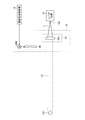
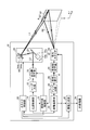
- FIG. 1 is a schematic configuration diagram when the laser radar device according to the first embodiment of the present invention shapes and irradiates a laser beam in a first irradiation shape.
- FIG. 2 is a schematic configuration diagram when the laser radar device according to the first embodiment of the present invention shapes and irradiates a laser beam in a second irradiation shape.
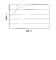
- FIG. 3 is a graph showing the relationship between the visibility and the transmittance of laser light.
- FIG. 4 is a schematic configuration diagram when the light transmission side optical system shapes the laser light into the first irradiation shape.
- FIG. 5 is a schematic configuration diagram when the light transmission side optical system shapes the laser light into the second irradiation shape.
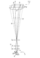
- FIG. 6 is a schematic view showing an example of the peripheral configuration including the light receiving side optical system and the light receiving element.
- FIG. 7 is a perspective view showing an example of a peripheral configuration including the light receiving side optical system and the light receiving element.
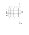
- FIG. 8 is a view showing a modification of the light receiving element.
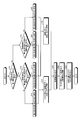
- FIG. 9 is a flowchart of an example of processing of the laser radar device according to the first embodiment of the present invention.
- FIG. 10 is a schematic configuration diagram when the laser radar device according to the second embodiment of the present invention shapes and irradiates a laser beam in a first irradiation shape.
- FIG. 11 is a schematic configuration diagram when the laser radar device according to the second embodiment of the present invention shapes and irradiates a laser beam in a second irradiation shape.
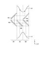
- FIG. 12 is a schematic configuration diagram of an intensity distribution reduction mechanism provided in a light transmission side optical system of a laser radar device according to a third embodiment of the present invention.
- FIG. 13 is an explanatory view of an intensity distribution reduction mechanism.
- FIG. 14 is a schematic explanatory view of a light emitting side optical system and an irradiation scanner of a laser radar device according to a fourth embodiment of the present invention.
- FIG. 15 is a schematic explanatory view of a light emitting side optical system and an irradiation scanner of a laser radar device according to a fourth embodiment of the present invention.
- FIG. 16 is a schematic explanatory view of a light emitting side optical system and an irradiation scanner of a laser radar device according to a fourth embodiment of the present invention.
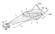
- FIG. 17 is a perspective view showing a configuration in which a laser radar device is mounted on a train traveling on a track.
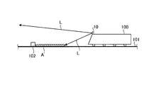
- FIG. 18 is a side view showing a configuration in which a laser radar device is mounted on a train traveling on a track.
- FIG. 19 is a perspective view showing a configuration in which a laser radar device is mounted on a vehicle.
- FIG. 1 is a schematic configuration diagram when the laser radar device 10 according to the first embodiment of the present invention shapes and irradiates the laser light L into a first irradiation shape LS1 (see FIG. 4).
- FIG. 2 is a schematic configuration diagram when the laser radar device 10 according to the first embodiment of the present invention shapes and irradiates the laser beam L into the second irradiation shape LS2 (see FIG. 5).
- the laser radar device 10 shown in FIG. 1 and FIG. 2 irradiates the laser to a predetermined measurement target area A set in advance in two modes of irradiating the laser with different shapes and scanning methods, and the measurement target area A 3D information can be generated.
- FIG. 3 is a graph showing the relationship between the visibility in the irradiation direction of the laser beam (hereinafter simply referred to as visibility) and the transmittance in the irradiation direction of the laser beam L (hereinafter simply referred to as transmittance).
- visibility the visibility in the irradiation direction of the laser beam
- transmittance the transmittance in the irradiation direction of the laser beam L
- the horizontal axis represents visibility on a logarithmic scale
- the vertical axis represents transmittance on a logarithmic scale.
- a curve C shown in FIG. 3 indicates a correlation curve between visibility and transmittance.
- the transmittance decreases as the visibility decreases as shown in FIG. 3 and increases as the visibility increases. That is, for example, when the laser radar device 10 is used in a large outdoor space, the visibility changes according to the change of the outdoor environment, and the transmittance changes according to the change of the visibility. Therefore, the laser radar device 10 performs the second irradiation of the first laser light L1 and the laser light L, in which the laser light L is shaped into the first irradiation shape LS1 according to the transmittance, that is, according to the visibility in the outdoor environment.
- the laser radar device 10 sets the irradiation shape of the laser light L as the first irradiation shape LS1 having a small irradiation area and a high irradiation intensity per unit area, and the visibility is predetermined If it is larger than the threshold value, the irradiation shape of the laser beam L is set to a second irradiation shape LS2 which has a large irradiation area and a low irradiation intensity per unit area.
- the second irradiation shape LS2 has a larger irradiation area than the first irradiation shape LS1. That is, the area of the cross section perpendicular to the irradiation direction of the second laser light L2 or the first laser light L1 is large.
- the laser radar device 10 sets the first irradiation shape LS1 to a point-like cross section perpendicular to the irradiation direction of the light beam of the first laser light L1, that is, a circular shape with a minute size, and the second irradiation shape.
- a cross section perpendicular to the irradiation direction of the light beam of the second laser light L2 is a line extending in the horizontal direction (first direction) X of the measurement object area A, and the measurement object area A according to the first irradiation shape LS1 In the horizontal direction X and in the vertical direction (second direction) Y orthogonal to the horizontal direction X, and in the vertical direction Y according to the second irradiation shape LS2.
- the irradiation shape of the laser beam L is the first irradiation shape LS1
- the intensity of the light beam of the laser beam L can be maximized.
- the irradiation shape of the laser beam L is the second irradiation shape LS2
- the irradiation area is larger than that of the first irradiation shape LS1, so the three-dimensional measurement rate for the measurement target area A is improved, and the measurement target area A is measured. Can be done in a short time.
- the position information of the laser light L included in the second reflected light R2 to be received is the first direction from the light receiving portion.
- the first irradiation shape LS1 and the second irradiation shape LS2 and the scanning performed according to them are not limited to these, and for example, the first irradiation shape LS1 is a line extending in the horizontal direction X, and the second irradiation shape LS2 is horizontal It may be a plane extending in the direction X and the vertical direction Y, and scanning in the vertical direction Y of the measurement target area A may be performed according to the first irradiation shape LS1, and may not be scanning according to the second irradiation shape LS2.
- the first irradiation shape LS1 or the second irradiation shape LS2 is formed into a line extending in the horizontal direction X to a half length or less of the measurement target area A, and the first irradiation shape LS1 or the second irradiation shape LS2
- the scanning may be performed in the horizontal direction X and the vertical direction Y of the measurement target area A.
- the laser radar device 10 irradiates the first laser beam L1 formed in a point shape which is the first irradiation shape LS1 while scanning in the horizontal direction X and the vertical direction Y of the measurement target area A, and the second irradiation shape LS2
- the second laser beam L2 shaped in a line extending in a horizontal direction X is irradiated while scanning in the vertical direction Y of the measurement target area A.
- the measurement target area A is an area set at a position away from the laser radar device 10 by a predetermined distance.
- the laser radar device 10 includes a laser light source 12, a light source control unit 14, a light transmitting side optical system 16, an irradiation shape control unit 18, an irradiation scanner 20, and a scanner control unit.
- a light receiving side optical system 24, a light receiving element 26, an amplifier circuit 28, a distance calculating unit 30, and an information generating unit 32 are provided.
- the light receiving unit of the present embodiment includes a light receiving element 26 and an amplifier circuit 28.
- an external device 34 is connected to the information generation unit 32 in a wired or wireless manner.
- the external device 34 is exemplified by a computer or the like mounted on a traveling body.
- the laser radar device 10 includes a storage unit and a processing unit.
- the storage unit includes, for example, storage devices such as a RAM, a ROM, and a flash memory, and stores software programs processed by the processing unit, data to be referred to by the software programs, and the like.
- the storage unit also functions as a storage area in which the processing unit temporarily stores processing results and the like.
- the processing unit reads out the software program and the like from the storage unit and processes the software program and the like to exhibit the function according to the contents of the software program.
- the processing unit functions as a light source control unit 14, an irradiation shape control unit 18, a scanner control unit 22, a distance calculation unit 30, and an information generation unit 32.
- the light source control unit 14, the irradiation shape control unit 18, the scanner control unit 22, the distance calculation unit 30, and the information generation unit 32 generate and output three-dimensional information of the measurement target area A.
- the laser light source 12 emits a light beam of the laser light L from the irradiation port 12 o (see FIGS. 4 and 5) toward the light sending side optical system 16 to emit light, that is, oscillate and emit light.
- the laser light source 12 preferably emits, for example, a laser beam L having a wavelength of 200 to 2000 nm.
- stable measurement can be realized by the laser light source 12 emitting a laser beam L having a wavelength of 800 to 2000 nm.
- the laser light source 12 is formed of, for example, a laser diode or the like, and emits the laser light L in a pulse shape based on the light emission command of the light source control unit 14.
- the light source control unit 14 controls the operation of the laser light source 12.
- the light source control unit 14 transmits information on the intensity of light emission of the laser light L to the irradiation shape control unit 18.
- the light source control unit 14 also has a master clock of the laser radar device 10, and transmits a pulse-like light emission synchronization signal to the distance calculation unit 30 simultaneously with the light emission of the laser light L.
- FIG. 4 is a schematic configuration diagram when the light transmitting side optical system 16 shapes the laser light L into the first irradiation shape LS1.
- FIG. 5 is a schematic configuration diagram when the light transmitting side optical system 16 shapes the laser light L into the second irradiation shape LS2.
- the light-transmission-side optical system 16 has a first irradiation shape LS1 or a second irradiation shape LS2 of the laser light L emitted from the irradiation port 12o of the laser light source 12. It shape
- the light transmitting side optical system 16 is inserted into and removed from the optical path of the laser light L by inserting and removing the basic optical system 36 that shapes the irradiation shape of the laser light L into the first irradiation shape LS1 or the second irradiation shape LS2. It is preferable to have the insertion / extraction optical element 38 which switches the irradiation shape of the light L between the first irradiation shape LS1 and the second irradiation shape LS2. In this case, the light transmission side optical system 16 can switch the irradiation shape of the laser light L easily and reliably.
- the light-transmission-side optical system 16 includes the basic optical system 36 that shapes the irradiation shape of the laser light L into the first irradiation shape LS1 having a small irradiation area; Insertion and removal for switching the irradiation shape of the laser light L to the second irradiation shape LS2 having a large irradiation area by being inserted into the light path and moved to the insertion position, that is, placed in the light path of the laser light L It is preferable to have the optical element 38.
- the light transmission side optical system 16 is disposed in the light path of the laser light L by the insertion / extraction optical element 38 being extracted with respect to the light path of the laser light L and moved from the insertion position to the extraction position.
- the irradiation shape of the laser beam L can be switched again to the first irradiation shape LS1 having a small irradiation area.
- the light transmission side optical system 16 can switch the irradiation shape of the laser light L more easily and reliably. Further, by selecting the insertion / extraction optical element 38, the light transmission side optical system 16 can appropriately select the second irradiation shape LS2.
- the basic optical system 36 includes an optical element 36 a fixedly provided on the optical path of the laser light L in the present embodiment.
- the basic optical system 36 is a single optical element 36 a in the present embodiment, the present invention is not limited to this, and a combination of a plurality of optical elements may be used.
- the optical element 36a has, for example, a curved surface on the incident side of the laser light L as a convex surface, and a curved surface on the emission side of the first laser light L1 formed into the first irradiation shape LS1 is a single-sided convex lens having a flat surface.
- the optical element 36a is preferably a collimator lens that is aberration-corrected to obtain parallel light, and in this case, the light beam of the reflected light R of the laser light L is not correctly collected at one point in the light receiving portion and an incomplete image is obtained. You can reduce what you can do.
- the insertion / extraction optical element 38 is an element for diffusing the light beam of the laser light L in the present embodiment.
- the insertion / extraction optical element 38 diffuses the light beam of the first laser light L1 formed into the first irradiation shape LS1 by the basic optical system 36 into a linear shape extending in the horizontal direction X to form an irradiation shape of the first laser light L1.
- the first irradiation shape LS1 is switched to the second irradiation shape LS2.
- the insertion / extraction optical element 38 is a single optical element.
- the present invention is not limited to this, and a combination of a plurality of optical elements may be used.
- the insertion / extraction optical element 38 makes it possible to appropriately select the second irradiation shape LS2 by selecting the shape and the configuration.
- the insertion / extraction optical element 38 includes, for example, a cylindrical concave lens having a flat surface on the incident side of the first laser beam L1 and a curved surface on the emission side of the second laser beam L2 shaped into the second irradiation shape LS2. .
- the insertion and extraction optical element 38 is connected to a drive motor 38M that drives the insertion and extraction optical element 38 between the insertion position and the extraction position.
- the drive motor 38M is connected to the irradiation shape control unit 18, and moves the insertion and removal optical element 38 to the insertion position based on the insertion command transmitted from the irradiation shape control unit 18. Further, the drive motor 38M moves the insertion and extraction optical element 38 to the extraction position based on the extraction command transmitted from the irradiation shape control unit 18.
- the light-transmission-side optical system 16 moves the insertion / extraction optical element 38 based on the insertion command and the extraction command transmitted from the irradiation shape control unit 18 to the drive motor 38M, thereby the light beam of the laser light L
- the irradiation shape for forming is switched between the first irradiation shape LS1 and the second irradiation shape LS2.
- the irradiation shape control unit 18 controls the light transmission side optical system 16 to control the irradiation shape for forming the laser light L to the first irradiation shape LS1 or the second irradiation shape LS2.
- the irradiation shape control unit 18 acquires information on the light emission intensity of the laser light L from the light source control unit 14. Further, the irradiation shape control unit 18 acquires information on the strength of the received signal from the amplifier circuit 28.
- the irradiation shape control unit 18 measures the visibility based on the information on the light emission intensity of the laser light L acquired from the light source control unit 14 and the information on the intensity of the reception signal acquired from the amplifier circuit 28.
- the irradiation shape control unit 18 enables measurement of visibility according to the capability of the laser radar device 10.
- the irradiation shape control unit 18 determines whether the measured visibility is equal to or larger than the threshold or smaller than the threshold. Further, the irradiation shape control unit 18 determines whether the measured visibility is equal to or larger than the threshold or smaller than the threshold. Thereby, the irradiation shape control unit 18 can determine the visibility according to the capability of the laser radar device 10.
- the irradiation shape control unit 18 may not acquire information on the intensity of light emission of the laser light L from the light source control unit 14 or acquire information on the intensity of the reception signal from the amplifier circuit 28. In this case, instead of measuring the visibility based on the information of the intensity of the light emission of the laser light L from the light source control unit 14 and the information of the intensity of the reception signal from the amplifier circuit 28, the irradiation shape control unit 18 Information of visibility that this visibility meter measures and outputs is received from a visibility meter as an ambient environment detection unit further provided in the radar device 10, and this visibility is equal to or greater than or less than the threshold value, or It is determined whether this visibility has become equal to or greater than the threshold. As a result, the irradiation shape control unit 18 can measure objective visibility with a visibility meter even under conditions such as when the apparatus is started, so that objective visibility can be determined.
- the irradiation shape control unit 18 controls the light transmitting side optical system 16 to form the irradiation shape of the laser beam L into the second irradiation shape LS2 when it is determined that the measured visibility is equal to or more than the threshold. Specifically, when the visibility is equal to or more than the threshold value, the irradiation shape control unit 18 does not issue a command to the drive motor 38M and holds it as it is when the insertion / extraction optical element 38 is in the insertion position. On the other hand, the irradiation shape control unit 18 inserts the insertion and extraction optical element 38 by transmitting an insertion command to the drive motor 38M when the insertion and extraction optical element 38 is in the extraction position when the visibility is equal to or greater than the threshold.
- the irradiation shape control unit 18 transmits, to the scanner control unit 22, second shape information which is information indicating that the irradiation shape is controlled to the second irradiation shape LS2.
- the irradiation shape control unit 18 controls the light transmitting side optical system 16 to form the irradiation shape of the laser light L into the first irradiation shape LS1. Specifically, in the case where the visibility is less than the threshold value, the irradiation shape control unit 18 does not issue a command to the drive motor 38M and holds it as it is when the insertion / extraction optical element 38 is at the extraction position. On the other hand, in the case where the visibility is less than the threshold and the insertion / extraction optical element 38 is in the insertion position, the irradiation shape control unit 18 transmits the extraction command to the drive motor 38M to remove the insertion / extraction optical element 38.
- the irradiation shape for forming the light beam of the laser beam L is switched from the second irradiation shape LS2 to the first irradiation shape LS1 by moving to the exit position. Then, the irradiation shape control unit 18 transmits, to the scanner control unit 22, first shape information that is information indicating that the irradiation shape is controlled to the first irradiation shape LS1.
- the irradiation shape control unit 18 determines whether the visibility is equal to or larger than the threshold value or smaller than the threshold value every predetermined time or continuously. That is, the irradiation shape control unit 18 can determine that the visibility is less than the threshold and is equal to or more than the threshold, and can determine that the visibility is more than the threshold and less than the threshold.
- the insertion optical transmission is sent to the drive motor 38M to move the insertion / extraction optical element 38 to the insertion position.
- the irradiation shape for forming is switched from the first irradiation shape LS1 to the second irradiation shape LS2.
- the irradiation shape control unit 18 transmits, to the scanner control unit 22, second shape information which is information equivalent to information indicating that the irradiation shape has been switched to the second irradiation shape LS2.
- the irradiation shape control unit 18 determines that the visibility has become equal to or more than the threshold value and is less than the threshold value, it transmits the extraction command to the drive motor 38M to move the insertion and extraction optical element 38 to the extraction position.
- the irradiation shape for forming the light beam is switched from the second irradiation shape LS2 to the first irradiation shape LS1.
- the irradiation shape control unit 18 transmits, to the scanner control unit 22, first shape information that is information corresponding to information indicating that the irradiation shape has been switched to the first irradiation shape LS1.
- the irradiation shape control unit 18 determines that the measured visibility has become equal to or more than the threshold when the peak value of the intensity of the received signal becomes equal to or more than the predetermined first threshold, and the light transmitting side optical system 16 irradiates the laser light L.
- the shape is preferably controlled to be formed into the second irradiation shape LS2. Since the peak value of the intensity of the received signal is the highest sensitivity among the intensities of the received signal when the visibility is high, the illumination shape control unit 18 sets the visibility threshold based on the peak value of the intensity of the received signal with high sensitivity. The above can be appropriately determined, and the irradiation shape of the laser beam L can be controlled to the second irradiation shape LS2.
- the irradiation shape control unit 18 determines that the measured visibility is a threshold It is preferable to control so that the light transmission side optical system 16 shapes the irradiation shape of the laser beam L into the second irradiation shape LS2 by determining that the amount is less than the second irradiation shape LS2.
- the irradiation shape control unit 18 can not detect the received signal gradually from the end of the light receiving unit, and accordingly appropriately determines that the visibility is less than the threshold based on the possibility of detection of the received signal.
- the irradiation shape of the laser beam L can be controlled to the first irradiation shape LS1.
- the laser radar device 10 uses the first threshold when determining that the visibility is less than the threshold and is greater than or equal to the threshold, and determines that the visibility is less than the threshold and less than the threshold.
- the second threshold is used, and two thresholds of the first threshold and the second threshold are provided so that a history (hysteresis) remains when switching the irradiation shape of the laser light L, but is limited thereto It is determined that the visibility is less than the threshold and is greater than or equal to the threshold using one threshold, and it is determined that the visibility is less than or equal to the threshold and less than the threshold, so that the laser does not have history (hysteresis)
- the irradiation shape of the light L may be switched.
- the laser radar device 10 switches the irradiation shape of the laser light L with the visibility being less than the threshold and the visibility being the threshold or more, substantially, the visibility is larger than the threshold It also includes switching the irradiation shape of the laser beam L below the threshold value.
- the irradiation scanner 20 irradiates the laser light L formed by the light transmitting side optical system 16 in the measurement target area A while scanning the laser light L according to the irradiation shape.
- the irradiation scanner 20 scans the first laser beam L1 whose irradiation shape is formed in a point shape as the first irradiation shape LS1 in the horizontal direction X and the vertical direction Y of the measurement target area A, respectively.
- the irradiation scanner 20 scans the second laser light L2 whose irradiation shape is formed in a line extending in the horizontal direction X as the second irradiation shape LS2 in the vertical direction Y of the measurement area A.
- the irradiation scanner 20 has a function of scanning the measurement target area A two-dimensionally as shown in FIG. 1 and FIG. 2, and a horizontal scanning unit 42 which scans the first laser beam L1 in the horizontal direction X; And a vertical scanning unit 44 for scanning the one laser light L1 or the second laser light L2 in the vertical direction Y.
- the horizontal scanning unit 42 and the vertical scanning unit 44 are, for example, galvano scanners, and include galvano mirrors 42a and 44a that are plane mirrors, and drive motors 42b and 44b that swing mirror surfaces of the galvano mirrors 42a and 44a. There is.
- the horizontal scanning unit 42 drives the drive motor 42 b under the control of the scanner control unit 22 to control the galvano mirror when the light transmission side optical system 16 shapes the irradiation shape of the laser light L into the first irradiation shape LS1. Swing 42a. Thereby, the angle of the horizontal direction of the first laser beam L1 shaped into the first irradiation shape LS1 by the light-transmission side optical system 16 is changed by the galvano mirror 42a, and is scanned in the horizontal direction X of the measurement area A .
- the horizontal scanning unit 42 stops the driving of the drive motor 42b under the control of the scanner control unit 22 when the light transmitting side optical system 16 shapes the irradiation shape of the laser light L into the second irradiation shape LS2.
- the galvano mirror 42a is fixed at a predetermined angle.
- the second laser beam L2 shaped into the second irradiation shape LS2 by the light emitting side optical system 16 has its horizontal angle fixed by the galvano mirror 42a.
- the drive motor 44b is driven under the control of the scanner control unit 22 to swing the galvano mirror 44a.
- the angle of the vertical direction of the first laser light L1 or the second laser light L2 reflected by the galvano mirror 42a is changed by the galvano mirror 44a, and is scanned in the vertical direction Y of the measurement area A.
- a configuration using a galvano scanner has been described as an example of the horizontal scanning unit 42 and the vertical scanning unit 44.
- the configuration is not limited to this. For example, using a polygon scanner having a polygon mirror Also good.
- the scanner control unit 22 controls the operation of the irradiation scanner 20. Specifically, the scanner control unit 22 receives the first shape information or the second shape information transmitted from the irradiation shape control unit 18, and the scan pattern is generated based on the received first shape information or the second shape information. Determine and scan based on the determined scan pattern.
- the scanner control unit 22 determines that the scanning pattern is to be scanned in the horizontal direction X and the vertical direction Y respectively, and the second shape information from the irradiation shape control unit 18 Is determined to cause the scanning pattern to scan in the vertical direction Y.
- the scanner control unit 22 controls the operation of the drive motors 42b and 44b based on a predetermined scanning pattern for each of scanning in the horizontal direction X and vertical direction Y and scanning in the vertical direction Y, respectively.
- the irradiation scanner 20 controlled by the scanner control unit 22 irradiates the first laser light L1 shaped into the first irradiation shape LS1 with the scanning according to the scanning pattern and irradiates the measurement target area A with this
- the points (areas) in the irradiated measurement target area A sequentially become the first measurement point S1.
- the scanner control unit 22 acquires information on mirror angles (light transmission control angles) of the galvano mirrors 42a and 44a corresponding to the first measurement points S1, and transmits these mirror angles to the information generation unit 32. .
- the irradiation scanner 20 controlled by the scanner control unit 22 irradiates the second laser light L2 shaped into the second irradiation shape LS2 with the scanning according to the scanning pattern and irradiates the measurement target area A with the irradiation.
- the points (areas) in the measured area A become the second measurement point S2 sequentially.
- the scanner control unit 22 acquires information on mirror angles (transmission control angles) of the galvano mirror 44 a corresponding to the second measurement points S 2, and transmits these mirror angles to the information generation unit 32.
- the information of the mirror angle (transmission control angle) of the galvano mirror 42a corresponds to the position information of the first measurement point S1 in the horizontal direction X, and the information of the mirror angle (transmission control angle) of the galvano mirror 44a. These correspond to position information of the first measurement point S1 or the second measurement point S2 in the vertical direction Y.
- the irradiation scanner 20 controlled by the scanner control unit 22 irradiates the measurement target area A while irradiating the measurement target area A while scanning the first laser beam L1 shaped into the first irradiation shape LS1, so
- the irradiation power density of the irradiated first laser light L1 can be increased to improve the signal intensity. Thereby, measurement performance can be ensured even under environmental conditions where the transmittance of the first laser light L1 is low, for example, in a fog environment or a rain environment.
- the irradiation scanner 20 controlled by the scanner control unit 22 scans the second laser beam L2 shaped into the second irradiation shape LS2 in a direction perpendicular to the extending direction of the second irradiation shape LS2.
- the three-dimensional measurement rate for the measurement target area A is improved, and the measurement of the measurement target area A can be performed in a short time.
- the light receiving side optical system 24 receives the first reflected light R1 reflected from each first measurement point S1 of the measurement target area A or the second reflected light R2 reflected from each second measurement point S2 of the measurement target area A And condense in the vertical direction Y.
- FIG. 6 is a schematic view showing an example of a peripheral configuration including the light receiving side optical system 24 and the light receiving element 26.
- FIG. 7 is a perspective view showing an example of a peripheral configuration including the light receiving side optical system 24 and the light receiving element 26.
- the light receiving side optical system 24 has a light receiving side lens 46, a relay lens 48, and a condensing lens 50.
- the light receiving side optical system 24 has a configuration in which one relay lens 48 and one focusing lens 50 are provided in FIG. 6, but it goes without saying that a lens unit in which a plurality of lenses are combined may be used.
- the light receiving side lens 46 receives the first reflected light R1 or the second reflected light R2 reflected by each first measurement point S1 or each second measurement point S2 of the measurement target area A, and each first measurement point S1.
- the image of each of the second measurement points S2 is formed at a predetermined position (image forming position) on the downstream side of the light receiving side lens 46.
- FIGS. 5 and 6 show the case where the second reflected light R2 reflected at each second measurement point S2 is received to form an image of each second measurement point S2, each The same applies to the case where the first reflected light R1 reflected at one measurement point S1 is received to form an image of each first measurement point S1.
- the relay lens 48 is disposed at the image forming position of the light receiving side lens 46 and, while holding the image forming information of the light receiving side lens 46 at the image forming position, substantially collimates the light flux thereafter and collects the image forming information as it is. Transmit to the light lens 50.
- the relay lens 48 is formed of, for example, a convex lens.
- the relay lens 48 is arranged at the image forming position of the light receiving side lens 46 in this embodiment, but the present invention is not limited to this.
- the relay lens 48 is located near the image forming position of the light receiving side lens 46 or behind the image forming position. It may be arranged.
- the condenser lens 50 is disposed downstream of the relay lens 48, and as shown in FIG. 7, for example, a cylindrical convex lens having a curved surface 50a on the incident side of the first reflected light R1 or the second reflected light R2 and a flat surface 50b on the emission side. It consists of The condenser lens 50 is formed so that the magnification of condensing in the vertical direction Y is larger than the magnification of condensing in the horizontal direction X. That is, the light collecting element 50 is a light receiving element 26 which is a line sensor extending in the horizontal direction X, ie, all parallel light fluxes of the first reflected light R1 or the second reflected light R2 transmitted from the relay lens 48.
- the light receiving side optical system 24 has a simple configuration in which three types of lenses are combined, and the light receiving side lens 46 forms an image, and the relay lens 48 and the focusing lens 50 condenses the image forming information on the light receiving element 26. It is possible to realize scanless on the light receiving side.
- the first reflected light R1 or the second reflected light R2 condensed toward the light receiving element 26 by the light receiving side optical system 24 will be collectively referred to as the reflected light R as appropriate.
- the light receiving element 26 and the amplifier circuit 28 constitute a light receiving unit of the present embodiment.
- the light receiving element 26 preferably includes a light receiving area of the reflected light R collected by the light receiving side optical system 24.
- the light receiving element 26 of the light receiving unit can receive the reflected light R of the entire area of the measurement target area A without scanning on the light receiving side regardless of the irradiation shape of the laser light L. Scanless can be realized and the configuration is simplified.
- the light receiving element 26 is a line sensor including a plurality of (five in the present embodiment) light receiving cells 26 a arranged in the horizontal direction X.
- Each light receiving cell 26 a is formed by a photoelectric conversion element (for example, a photodiode) that receives the reflected light R and converts it into a current, and is formed by a single element having a single pixel. Therefore, it is possible to respond to the short pulse first laser beam L1 or the second laser beam L2.
- the measurement target area A is divided into five divided areas Aa in accordance with five light receiving cells 26a. Then, the reflected light R from the measurement target area A is spatially resolved into five corresponding to the divided area Aa, and is received by the light receiving cell 26a corresponding to the divided area Aa. In this case, the reflected light R from the divided area Aa is condensed in the vertical direction Y by the condensing lens 50, and is received by the corresponding light receiving cell 26a. Therefore, the parallel light flux of the reflected light R from the measurement target area A, that is, all the imaging information is collected on the light receiving element 26.
- the light receiving element 26 receives the reflected light R collected by the light receiving side optical system 24, and outputs a reception signal based on the first laser light L1 or the second laser light L2 included in the received reflected light R.
- the amplifier circuit 28 amplifies the reception signal output from the light receiving element 26 as a voltage signal. Since the reception signal output from the light receiving element 26 is a weak current signal, the amplifier circuit 28 converts the current signal into a voltage signal and outputs the voltage signal to the distance calculation unit 30.
- the distance calculation unit 30 calculates distance information of each first measurement point S1 or each second measurement point S2 of the measurement target area A based on the reception signal amplified by the amplifier circuit 28.
- the distance calculation unit 30 acquires the pulse-like light emission synchronization signal transmitted from the light source control unit 14 and the reception signal transmitted from the amplifier circuit 28, and the measurement is performed when the first laser light L1 or the second laser light L2 is irradiated.
- the distance to each first measurement point S1 or each second measurement point S2 of the target area A is calculated, and the distance information is transmitted to the information generation unit 32.
- the distance calculation unit 30 measures the time from the emission of the first laser light L1 or the second laser light L2 to the reception of the reflected light R based on the light emission synchronization signal and the reception signal. At the same time, the distance to each first measurement point S1 or each second measurement point S2 that has reflected the first laser beam L1 or the second laser beam L2 is calculated based on this measurement time. In addition, the distance calculation unit 30 may transmit the light reception intensity included in the received signal to the information generation unit 32 in association with the distance information together with the distance information.
- the distance calculation unit 30 calculates position information in the horizontal direction X of each first measurement point S1 or each second measurement point S2 of the measurement target area A based on the reception signal amplified by the amplifier circuit 28. Specifically, the distance calculation unit 30 acquires pixel information (number) of the light receiving cell 26a that has received the reflected light R, and the horizontal direction of each first measurement point S1 or each second measurement point S2 from this pixel information The position information of X is calculated, and the position information is transmitted to the information generation unit 32.
- the distance calculation unit 30 determines each of the measurement target area A based on the reception signal amplified by the amplifier circuit 28.
- the position information of the first measurement point S1 in the horizontal direction X may not be calculated, and the position information may not be transmitted to the information generation unit 32.
- the information generation unit 32 corresponds to each first measurement point S1 transmitted from the scanner control unit 22 instead of the position information of the first measurement point S1 transmitted from the distance calculation unit 30 in the horizontal direction X.
- the position information of the horizontal direction X of each first measurement point S1 of the measurement target area A calculated based on the information of the mirror angle (light transmission control angle) of the galvano mirror 42a to be used is used.
- the information generation unit 32 receives the information of the mirror angle (transmission control angle) of the galvano mirror 44 a corresponding to each first measurement point S1 or each second measurement point S2 transmitted from the scanner control unit 22, and this mirror Based on the information on the corners, position information in the vertical direction Y of each first measurement point S1 or each second measurement point S2 of the measurement target area A is calculated.
- the information generation unit 32 receives the position information of the first measurement points S1 of the measurement target area A or the second measurement points S2 transmitted from the distance calculation unit 30 in the horizontal direction X.
- the information generation unit 32 calculates positional information of each first measurement point S1 or each second measurement point S2 in the vertical direction Y calculated based on the information of the mirror angle, and each first measurement point S1 received from the distance calculation unit 30. Alternatively, based on the position information in the horizontal direction X of each second measurement point S2, coordinate information at each first measurement point S1 or each second measurement point S2 is acquired, and a plurality of each existing in the measurement target area A Three-dimensional information of the measurement target area A is generated from the coordinate information distribution of the first measurement point S1 or each second measurement point S2. In this configuration, it is not necessary to acquire spatial position coordinates of the received signal by the visual field scan on the light receiving side, so the load of signal processing for generating three-dimensional information can be reduced.
- the three-dimensional information of the measurement target area A generated by the information generation unit 32 is transmitted to an external device 34 (for example, a computer or the like mounted on a traveling object) by wire or wireless, and is used by the external device 34. .
- the information generation unit 32 when the light transmission side optical system 16 shapes the irradiation shape of the laser light L into the first irradiation shape LS1, position information in the horizontal direction X of each first measurement point S1 from the distance calculation unit 30.
- the information generation unit 32 acquires coordinate information at each of the first measurement points S1 based on the position information of each of the first measurement points S1 in the horizontal direction X and the vertical direction Y calculated based on the information of the mirror angle. Then, three-dimensional information of the measurement target area A is generated from the coordinate information distribution of each of the plurality of first measurement points S1 existing in the measurement target area A.
- FIG. 8 is a view showing a modified example of the light receiving element 26.
- the light receiving element 26 is provided with one line sensor in which the light receiving cells 26a are arranged horizontally in the horizontal direction X.
- a plurality of (for example, three) line sensors Alternatively, the line sensor array 52 may be arranged in an array in the vertical direction Y. In this configuration, the remaining two line sensors 26 aligned in the vertical direction Y are preliminarily disposed, and the light receiving elements 26 (line sensors 26) by the light receiving side optical system 24 are operated during operation of the laser radar device 10.
- the line sensor 26 to which the reflected light R is condensed can be used even when the condensing position on the) is shifted or the condensing size is expanded from the optimum point. According to this, the reflected light R can be reliably received by the light receiving element, and measurement quality can be secured.
- the light receiving element 26 can be appropriately changed according to the first irradiation shape LS1 and the second irradiation shape LS2.
- the light receiving element 26 is a planar shape extending the second irradiation shape LS2 in the horizontal direction X and the vertical direction Y
- reflections collected by the light receiving side optical system 24 can be obtained by arranging the light receiving cells 26a in a planar shape.
- the second irradiation shape LS2 is in the form of a line extending in the horizontal direction X as described above, it is preferable that the light receiving element 26 be a line sensor or a line sensor array 52 in which several line sensors are arranged in the vertical direction Y.
- the load on the processing unit can be reduced, and measurement of the measurement target area A can be made without waste.
- FIG. 9 is a flowchart of an example of processing of the laser radar device according to the first embodiment of the present invention. The processing method executed by the laser radar device 10 will be described with reference to FIG.
- the irradiation shape control unit 18 in the laser radar device 10 determines whether the irradiation shape of the laser light L is shaped into the first irradiation shape LS1 (step S10). Then, the irradiation shape control unit 18 acquires information of the intensity of light emission of the laser light L from the light source control unit 14 and acquires information of the intensity of the reception signal from the amplifier circuit 28.
- the irradiation shape control unit 18 determines that the peak value of the intensity of the reception signal acquired from the amplifier circuit 28 is equal to or more than a predetermined first threshold. It is determined whether there is any (step S12).
- the irradiation shape control unit 18 determines that the measured visibility is not greater than the threshold, The light transmitting side optical system 16 is controlled to maintain the irradiation shape of the laser light L at the first irradiation shape LS1 (step S14). Specifically, when the irradiation shape control unit 18 determines that the visibility remains below the threshold, it does not transmit a command to the drive motor 38M, and holds the insertion / extraction optical element 38 at the extraction position, thereby the laser beam The irradiation shape for forming the light beam of L is maintained at the first irradiation shape LS1. Then, the irradiation shape control unit 18 transmits the first shape information, which is information indicating that the irradiation shape is controlled to the first irradiation shape LS1, to the scanner control unit 22, and the process proceeds to step S24.
- the first shape information which is information indicating that the irradiation shape is controlled to the first irradiation shape LS1, to the scanner control unit 22, and
- the irradiation shape control unit 18 determines that the measured visibility is equal to or higher than the threshold and transmits The light side optical system 16 is controlled to switch the irradiation shape of the laser beam L from the first irradiation shape LS1 to the second irradiation shape LS2 (step S16). Specifically, when the irradiation shape control unit 18 determines that the visibility is less than the threshold and becomes equal to or more than the threshold, the insertion / detachment optical element 38 is moved to the insertion position by transmitting the insertion command to the drive motor 38M.
- the irradiation shape for shaping the light beam of the laser light L is switched from the first irradiation shape LS1 to the second irradiation shape LS2. Then, the irradiation shape control unit 18 transmits the second shape information, which is information indicating that the irradiation shape is controlled to the second irradiation shape LS2, to the scanner control unit 22, and the process proceeds to step S26.
- the irradiation shape control unit 18 determines that the peak value of the intensity of the reception signal acquired from the amplifier circuit 28 is less than the predetermined second threshold. It is determined whether there is any (step S18).
- the irradiation shape control unit 18 determines that the measured visibility is less than the threshold and sends The light side optical system 16 is controlled to switch the irradiation shape of the laser beam L from the second irradiation shape LS2 to the first irradiation shape LS1 (step S20). Specifically, when the irradiation shape control unit 18 determines that the visibility has become equal to or more than the threshold value and is less than the threshold value, the extraction optical element 38 is moved to the extraction position by transmitting the extraction command to the drive motor 38M.
- the irradiation shape for shaping the light beam of the laser light L is switched from the second irradiation shape LS2 to the first irradiation shape LS1. Then, the irradiation shape control unit 18 transmits the first shape information, which is information indicating that the irradiation shape is controlled to the first irradiation shape LS1, to the scanner control unit 22, and the process proceeds to step S24.
- the irradiation shape control unit 18 determines that the measured visibility is not less than the threshold, The light transmitting side optical system 16 is controlled to maintain the irradiation shape of the laser light L at the second irradiation shape LS2 (step S22). Specifically, when the irradiation shape control unit 18 determines that the visibility remains above the threshold value, the laser light L is not transmitted to the drive motor 38M, and the insertion and removal optical element 38 is held at the insertion position. The irradiation shape for shaping the light beam of the light source is maintained at the second irradiation shape LS2. Then, the irradiation shape control unit 18 transmits the second shape information, which is information indicating that the irradiation shape is controlled to the second irradiation shape LS2, to the scanner control unit 22, and the process proceeds to step S26.
- the second shape information which is information indicating that the irradiation shape is controlled to the second irradiation shape LS2, to the scanner control unit 22, and the process
- the scanner control unit 22 receives the first shape information transmitted from the irradiation shape control unit 18 in step S14 or step S20, and the irradiation scanner 20 emits the laser light L and the irradiation shape is the first irradiation shape LS1. It controls so that it irradiates, making a scan according to (step S24). Specifically, the scanner control unit 22 determines the scanning pattern to be scanned in the horizontal direction X and the vertical direction Y based on the received first shape information, and based on the determined scanning pattern, the driving motor By controlling the operation so as to swing 42b and 44b, the irradiation scanner 20 scans and irradiates the first laser beam L1 formed into the first irradiation shape LS1.
- the scanner control unit 22 acquires the mirror angles (light transmission control angles) of the galvano mirrors 42a and 44a corresponding to the first measurement points S1 which are points in the irradiated measurement target area A, and Is transmitted to the information generation unit 32.
- the laser radar device 10 scans the first laser beam L1 whose irradiation shape is the first irradiation shape LS1 in the measurement target area A, and receives the first reflected light R1 from the measurement target area A. The process then proceeds to step S28.
- the scanner control unit 22 receives the second shape information transmitted from the irradiation shape control unit 18 in step S16 or step S22, and the irradiation scanner 20 emits the laser light L and the irradiation shape is the second irradiation shape LS2. It controls so that it irradiates, making a scan according to (step S26). Specifically, the scanner control unit 22 determines the scanning pattern to be scanned in the vertical direction Y based on the received second shape information, and swings the drive motor 44 b based on the determined scanning pattern. By controlling the operation as described above, the irradiation scanner 20 scans and irradiates the second laser beam L2 shaped into the second irradiation shape LS2.
- the scanner control unit 22 acquires mirror angles (light transmission control angles) of the galvano mirror 44a corresponding to the respective second measurement points S2 which are points in the irradiated measurement target area A, and these mirrors The corner is transmitted to the information generation unit 32.
- the laser radar device 10 scans the second laser beam L2 whose irradiation shape is the second irradiation shape LS2 in the measurement target area A, and receives the second reflected light R2 from the measurement target area A. The process then proceeds to step S28.
- the light receiving element 26 receives the reflected light R from the measurement target area A, and the first laser light included in the reflected light R A reception signal based on L1 or the second laser light L2 is output to the amplifier circuit 28, and the amplifier circuit 28 converts the reception signal output from the light receiving element 26 from a current signal into a voltage signal, and converts the converted reception signal into a distance It outputs to the calculating part 30 (step S28).
- the distance calculation unit 30 calculates the distance information of each first measurement point S1 or each second measurement point S2 of the measurement target area A based on the reception signal output from the amplifier circuit 28 when the light reception unit performs the process of step S28. Are calculated (step S30). Specifically, the distance calculation unit 30 acquires the pulse-like light emission synchronization signal transmitted from the light source control unit 14 and the reception signal output from the amplifier circuit 28, and based on the light emission synchronization signal and the reception signal, The time from the emission of the first laser light L1 or the second laser light L2 to the reception of the reflected light R was measured, and the first laser light L1 or the second laser light L2 was reflected based on this measurement time.
- the distance to each first measurement point S1 or each second measurement point S2 of the measurement target area A is calculated.
- the distance calculation unit 30 transmits the calculated distance information to the information generation unit 32.
- the distance calculation unit 30 may transmit the light reception intensity included in the received signal to the information generation unit 32 in association with the distance information together with the distance information.
- the distance calculation unit 30 calculates position information in the horizontal direction X of each first measurement point S1 or each second measurement point S2 of the measurement target area A based on the reception signal output from the amplifier circuit 28. Specifically, the distance calculation unit 30 acquires pixel information (number) of the light receiving cell 26a that has received the reflected light R, and the horizontal direction of each first measurement point S1 or each second measurement point S2 from this pixel information The position information of X is calculated, and the position information is transmitted to the information generation unit 32.
- the information generation unit 32 receives the distance information transmitted when the distance calculation unit 30 performs the process of step S30. Further, the information generation unit 32 receives information of the mirror angle corresponding to each first measurement point S1 or each second measurement point S2 from the scanner control unit 22, and from the distance calculation unit 30, each first measurement point S1 or each Positional information of the second measurement point S2 in the horizontal direction X is received. The information generation unit 32 measures the area to be measured A based on the distance information from the distance calculation unit 30 and the information (position information) on the mirror angle from the scanner control unit 22 or the position information from the distance calculation unit 30. Three-dimensional information is generated (step S32).
- the information generation unit 32 uses only the information on the mirror angles of the galvano mirrors 42a and 44a from the scanner control unit 22 as position information.
- information on the mirror angle of the galvano mirror 44a (position information) from the scanner control unit 22 and the position information from the distance calculation unit 30 may be combined and used as position information.
- the information generation unit 32 receives the information (position information) of the mirror angle of the galvano mirror 44a from the scanner control unit 22 and the distance calculation unit 30. Are combined and used as position information.
- the information generation unit 32 transmits the generated three-dimensional information of the measurement target area A to the external device 34, thereby storing the three-dimensional information in the external device 34 or displaying the three-dimensional information on the display Can.
- the laser radar device 10 determines that the visibility in the irradiation direction of the laser light L is less than the threshold, and when it determines that the visibility of the laser light L is less than the threshold, it changes to less than the threshold.
- the irradiation shape was controlled to the first irradiation shape LS1 with a small irradiation area, and it was determined that the visibility in the irradiation direction of the laser light L was a state above the threshold, and changed from a state below the threshold to a state above the threshold If it is determined that the irradiation shape is determined, the irradiation shape is controlled to the second irradiation shape LS2 having a large irradiation area.
- the laser radar device 10 can detect an obstacle while suppressing the power consumption of the device even when the transmittance of the light beam of the laser beam changes due to the change of the outdoor environment.
- the laser radar device 10 enables detection of an obstacle corresponding quickly to a change in the outdoor environment such as a change in visibility. That is, when the visibility is smaller than the threshold and the visibility becomes smaller than the threshold, the laser radar device 10 is a measurement target while scanning the first laser beam L1 formed into the first irradiation shape LS1. Since the area A is irradiated, the irradiation power density of the first laser light L1 irradiated to the area A to be measured can be increased to improve the signal intensity.
- the measurement performance of the measurement target area A can be secured even under environmental conditions where the transmittance of the first laser light L1 is low, for example, in a fog environment or a rain environment.
- the laser radar device 10 when the visibility is larger than the threshold and the visibility is larger than the threshold, the laser radar device 10 generates the second laser light L2 shaped into the second irradiation shape LS2 as the second irradiation shape LS2. Since the measurement target area A is irradiated while scanning in a direction perpendicular to the direction in which the direction is extended, the three-dimensional measurement rate for the measurement target area A is improved, and measurement of the measurement target area A can be performed in a short time.
- the laser radar device 10 automatically switches between the first irradiation shape LS1 and the second irradiation shape LS2 by threshold processing, the determination and operation by the operator become unnecessary.
- the present invention is not limited to this, information of visibility is displayed for the operator, the operator confirms the information of visibility, and the first irradiation shape LS1 and the second irradiation shape LS2 are manually operated. It is good also as changing by.
- the laser radar device 10 provides two thresholds of the first threshold and the second threshold so that the history (hysteresis) remains when switching the irradiation shape of the laser light L in the determination of visibility.
- the present invention is not limited to this, and it is determined that the visibility is less than the threshold and is greater than or equal to the threshold using one threshold, and it is determined that the visibility is less than or equal to the threshold and less than the threshold.
- the irradiation shape of the laser beam L may be switched so as not to occur.
- the laser radar device 10 determines the visibility based on the intensity of the received signal acquired from the amplifier circuit 28 in the present embodiment, but the present invention is not limited to this.
- the visibility information that this visibility meter measures and outputs may be received, and the information of this visibility may be determined. In this case, objective visibility can be determined even under conditions such as when the laser radar device 10 is started up.
- the laser radar device 10 appropriately changes the combination of the first irradiation shape LS1 and the second irradiation shape LS2 under the condition that the irradiation area of the first irradiation shape LS1 is smaller than the irradiation area of the second irradiation shape LS2. be able to.
- the laser radar device 10 may not scan the second irradiation shape LS2 according to the second irradiation shape LS2 as a planar shape extending in the horizontal direction X and the vertical direction Y. In this case, the laser radar device 10
- the three-dimensional measurement rate is further improved, and measurement of the measurement target area A can be performed in a short time.
- the laser radar device 10 can adopt a third irradiation shape in addition to the first irradiation shape LS1 and the second irradiation shape LS2.
- the irradiation shape having a large irradiation area is used to measure the measurement target area A.
- the third irradiation shape is exemplified as a line extending in the horizontal direction X by a half length of the second irradiation shape LS2 when the irradiation area is intermediate between the first irradiation shape LS1 and the second irradiation shape LS2 Ru.
- FIG. 10 is a schematic configuration diagram when the laser radar device 10 according to the second embodiment of the present invention shapes and irradiates the laser light L into the first irradiation shape LS1.
- FIG. 11 is a schematic configuration diagram when the laser radar device 10 according to the second embodiment of the present invention shapes the laser light into the second irradiation shape LS2 and irradiates it.
- the laser radar device 10 according to the second embodiment is the light receiving scanner in the incident side of the first reflected light R1 or the second reflected light R2 of the light receiving side optical system 24 in the laser radar device 10 according to the first embodiment. 54 is additionally provided.
- the laser radar device 10 according to the second embodiment is modified in such a manner that the scanner control unit 22 controls not only the irradiation scanner 20 but also the light receiving scanner 54.
- the laser radar device 10 according to the second embodiment uses the same code group as that of the first embodiment for the same configuration as that of the first embodiment, and the detailed description thereof will be omitted.
- the light receiving scanner 54 has a function of scanning the measurement target area A two-dimensionally, and has a horizontal scanning unit that scans the first reflected light R1 in the horizontal direction X, and the first reflected light R1. Or a vertical scanning unit for scanning the second reflected light R2 in the vertical direction Y.
- the horizontal scanning unit and the vertical scanning unit are formed of, for example, a galvano scanner, and include a galvano mirror that is a flat mirror, and a drive motor that swings a mirror surface of the galvano mirror.
- the light receiving scanner 54 performs scanning in the same manner as the irradiation scanner 20, so detailed description of the operation will be omitted.
- the configuration using the galvano scanner has been described as an example of the horizontal scanning unit and the vertical scanning unit.
- the present invention is not limited to this configuration.
- a polygon scanner having a polygon mirror may be used. .
- the scanner control unit 22 in the laser radar device 10 controls the operation of the light receiving scanner 54 in addition to the operation of the irradiation scanner 20.
- the scanner control unit 22 controls the operation so that the operation of the irradiation scanner 20 and the operation of the light receiving scanner 54 correspond to each other. That is, the scanner control unit 22 controls the operation of the light receiving scanner 54 so as to correspond to the coordinates of each of the first measurement points S1 and each of the second measurement points S2 determined according to the control of the operation of the irradiation scanner 20.
- the scanner control unit 22 receives and receives the first shape information or the second shape information transmitted from the irradiation shape control unit 18 not only for the irradiation scanner 20 but also for the light receiving scanner 54.
- a scan pattern is determined based on the shape information or the second shape information, and a scan is performed based on the determined scan pattern.
- the scanner control unit 22 receives not only the irradiation scanner 20 but also the light receiving scanner 54, the first shape information from the irradiation shape control unit 18, the scanner control unit 22 causes the scanning pattern to scan in the horizontal direction X and the vertical direction Y, respectively.
- the second shape information is received from the irradiation shape control unit 18, the scanning pattern is determined to be scanned in the vertical direction Y.
- the scanner control unit 22 applies not only the irradiation scanner 20 but also the light receiving scanner 54 based on a predetermined scanning pattern for each of scanning in the horizontal direction X and vertical direction Y and scanning in the vertical direction Y, respectively. Control the operation of the drive motor.
- the laser radar device 10 has a light receiving scanner 54, and the light receiving scanner 54 scans on the light receiving side of the reflected light R as the irradiation scanner 20 scans on the irradiation side of the laser light L. Therefore, even when the light receiving unit does not include the light receiving area of the reflected light R collected by the light receiving side optical system 24, the reflected light R in the entire area of the measurement target area A can be received.
- FIG. 12 is a schematic configuration diagram of an intensity distribution reduction mechanism 60 provided in the light transmission side optical system 16 of the laser radar device 10 according to the third embodiment of the present invention.
- FIG. 13 is an explanatory view of the intensity distribution reduction mechanism 60.
- the laser radar device 10 according to the third embodiment is the laser radar device 10 according to the first embodiment, in which an intensity distribution reducing mechanism 60 is additionally provided in the light sending side optical system 16.
- the laser radar device 10 according to the third embodiment uses the same code group as that of the first embodiment for the same configuration as that of the first embodiment, and the detailed description thereof will be omitted.
- the intensity distribution reducing mechanism 60 is formed in a line shape, and the intensity distribution is inverted by the normal distribution laser beam LU having the intensity distribution in the line direction and the inverting optical system.
- This is an optical mechanism that reduces the intensity distribution in the linear direction by superimposing the population inversion laser light LR.
- the normal distribution laser light LU is shaped into a second irradiation shape LS2 which is a line shape extending in the horizontal direction X in the present embodiment, and the second laser light L2 having an intensity distribution of Gaussian distribution (normal distribution) in the horizontal direction X Is exemplified, but not limited thereto.
- the plurality of inverting optical systems 60a are directed in the direction and line direction of the second laser light L2 exemplified by the normal distribution laser light LU of the inverting optical system 60a. They are arranged at intervals equivalent to the thickness t in the vertical direction.
- the linear direction of the second laser beam L2 exemplified by the normal distribution laser beam LU corresponds to the horizontal direction X. Therefore, the linear direction of the normal distribution laser beam LU is referred to as the horizontal direction X in the following description of the third embodiment.
- the irradiation direction of the second laser light L2 exemplified in the normal distribution laser light LU corresponds to the Z direction (see FIGS.
- the normal distribution laser light LU may be used.
- a direction perpendicular to the horizontal direction X which is the irradiation direction of the second laser light L2 and the linear direction illustrated, corresponds to the vertical direction Y in the present embodiment. Therefore, the irradiation direction of the normal distribution laser light LU is referred to as the Z direction in the following description of the third embodiment.
- the direction perpendicular to the horizontal direction X which is the direction of irradiation of the normal distribution laser light LU and the linear direction, will be referred to as the vertical direction Y in the following description of the third embodiment.
- the intensity distribution reducing mechanism 60 is configured such that a plurality of inverting optical systems 60a having a thickness t in the vertical direction Y are arranged along the vertical direction Y with a spacing of t between them. It is done.
- the thickness and the interval of the inverting optical system 60a are both t, the present invention is not limited thereto. If the sum of the intervals of the plurality of inverting optical systems 60a in the vertical direction Y is substantially equal, the intensity of the normal distribution laser light LU after passing through the intensity distribution reducing mechanism 60 and the intensity of the inversion distribution laser light LR , And so the intensity distribution in the horizontal direction X of the normally distributed laser beam LU can be reduced.
- both the thickness and the interval of the inverting optical system 60a be t. In this case, the intensity distribution in the horizontal direction X of the normally distributed laser beam LU is more reliable Can be reduced to
- the reversal optical system 60a irradiates the normal distribution laser beam LU to the two first mirror members 60b at both ends of the three first mirror members 60b and the three first mirror members 60b.
- two second mirror members 60c provided in a direction. All of the three first mirror members 60b are in any one of the horizontal directions X (counterclockwise in FIG. 13) which are linear directions with respect to the Z direction which is the irradiation direction of the normal distribution laser light LU. They are arranged side by side in the horizontal direction X at an inclination of 45 degrees.
- Each of the two second mirror members 60c is 45 in the other horizontal direction X (clockwise in FIG. 13) which is a linear direction with respect to the Z direction which is the irradiation direction of the normal distribution laser light LU. Are arranged at an angle.
- Each of the three first mirror members 60b has a length sufficient to cover half of the optical path width in the horizontal direction X of the normal distribution laser light LU, that is, the optical path width in the horizontal direction X of the normal distribution laser light LU. ⁇ 2/2 times the length.
- the one disposed at the center in the horizontal direction X is disposed so as to cover the area B2 of one half of the optical path width in the horizontal direction X of the normally distributed laser light LU. Ru.
- the three first mirror members 60b one disposed on one side (left side in FIG.
- the one disposed on the other side (right side in FIG. 13) in the horizontal direction X is the other half of the light path width in the horizontal direction X of the normal distribution laser light LU.
- Each of the two second mirror members 60c has a length sufficient to cover half of the optical path width in the horizontal direction X of the normal distribution laser light LU, that is, the optical path width in the horizontal direction X of the normal distribution laser light LU. ⁇ 2/2 times the length.
- those disposed close to one side in the horizontal direction X (left side in FIG. 13) have any one of the above-described ones of the optical path width in the horizontal direction X of the normally distributed laser light LU. It arrange
- those disposed close to either side in the horizontal direction X (right side in FIG. 13) are the other side in the optical path width in the horizontal direction X of the normally distributed laser light LU. Are arranged to cover the half area B3 of
- the normal distribution laser beam LU is formed in a line shape extending in a region B2 and a region B3 in the horizontal direction X, and has an intensity distribution of Gaussian distribution in the horizontal direction X. Further, in the normal distribution laser light LU, the optical path width straddles the region B2 and the region B3.
- the normally distributed laser beam LU passing through the area B2 before passing through the reversing optical system 60a is either the first mirror member 60b disposed at the center in the horizontal direction X or one side in the horizontal direction X as shown in FIG.
- the normally distributed laser beam LU passing through the area B3 before passing through the inverting optical system 60a is a first mirror member 60b disposed on the other side (right side in FIG. 13) in the horizontal direction X as shown in FIG.
- the light beam is sequentially reflected by the first mirror member 60b disposed at the center in the horizontal direction X, and passes through the area B2 after passing through the inverting optical system 60a.
- the reversal optical system 60a switches the half area of the normal distribution laser light LU by changing the half area of the normal distribution laser light LU, ie, the area B2 of one half of the normal distribution laser light LU and the area B3 of the other half.
- the intensity distribution of the normal distribution laser light LU can be inverted and converted into the inversion distribution laser light LR.
- the intensity distribution reducing mechanism 60 alternately provides, in the vertical direction Y, a region with a width t where the inverting optical system 60a is provided and a region with a width t where the inverting optical system 60a is not provided. Therefore, the intensity distribution reducing mechanism 60 has a width t, which is the light distribution of the inverted distribution laser light LR having a width t, obtained by inverting the intensity distribution of the normal distribution laser light LU by the inversion optical system 60a.
- the normal distribution laser light LU can be converted into mixed laser light alternately arranged in the vertical direction Y.
- the mixed laser beam is a laser beam in which the intensity distribution in the horizontal direction X is reduced since the normal distribution laser beam LU and the reverse distribution laser beam LR mutually cancel the intensity distribution in the horizontal direction X.
- the intensity distribution reducing mechanism 60 reduces the intensity distribution in the horizontal direction X of the normal distribution laser light LU.
- the light transmission side optical system 16 is provided with the intensity distribution reduction mechanism 60, and the intensity distribution reduction mechanism 60 is the intensity distribution of the normal distribution laser light LU in the horizontal direction X. Since it is possible to reduce, that is, to reduce the intensity distribution in the linear direction of the laser beam shaped into the line shape, the accuracy of obstacle detection when using the laser beam shaped into the line shape can be reduced. It can be improved.
- the laser radar device 10 according to the third embodiment reduces the intensity distribution in the line direction in the normal distribution laser light LU after being formed into a line shape.
- the laser radar device 10 according to the third embodiment is not limited to this, and the intensity distribution in the line direction may be reduced in the normal distribution laser light before being formed into the line shape. Also in this case, in the case of the normally distributed laser light LU after being shaped into a line, the same effect as in the case of reducing the intensity distribution in the line direction can be obtained.
- FIG. 14, FIG. 15 and FIG. 16 are all schematic explanatory views of the light transmission side optical system 16 and the irradiation scanner 20 of the laser radar device 10 according to the fourth embodiment of the present invention.
- the laser radar device 10 according to the fourth embodiment is the laser radar device 10 according to the first embodiment in which the insertion / extraction optical element 38 provided in the light transmission side optical system 16 is changed to the insertion / extraction optical element 62 It is. Accordingly, in the laser radar device 10 according to the fourth embodiment, the optical elements constituting the basic optical system 36 and the irradiation scanner 20 are shifted from the area where the second laser light L2 is condensed by the insertion / extraction optical element 62. It has been changed to be placed.
- the laser radar device 10 according to the fourth embodiment uses the same code group as that of the first embodiment for the same configuration as that of the first embodiment, and the detailed description thereof will be omitted.
- FIG. 14 shows the case where the optical system of the irradiation scanner 20, that is, the galvano mirrors 42a and 44a needs to be miniaturized, or the scanning speed and accuracy of the irradiation scanner 20.
- the irradiation area of the first laser beam L1 and the second laser beam L2 irradiated to the irradiation scanner 20 is limited.
- FIG. 6 illustrates an event that may occur in the light transmission side optical system 16 in such a case. As shown in FIG.
- the laser radar device 10 emits laser light L from the irradiation port 12 o of the laser light source 12, and the optical included in the basic optical system 36 in the light transmission side optical system 16.
- the element 36a and the insertion / extraction optical element 38 at the insertion position are passed through to form the second laser light L2
- the outer peripheral portion L2o of the light beam of the second laser light L2 fits in the galvano mirrors 42a and 44a of the irradiation scanner 20. There is a possibility that it becomes vignetted and can not be used by not having it.
- FIG. 15 illustrates a mode for avoiding the event illustrated in FIG. 14, and a schematic configuration of the light transmission side optical system 16 and the irradiation scanner 20 of the laser radar device 10 according to the fourth embodiment of the present invention. It is illustrated.
- the laser radar device 10 according to the fourth embodiment has an insertion / extraction optical element 62 instead of the insertion / extraction optical element 38.
- the insertion / extraction optical element 62 is an element that condenses the light beam of the laser light L in the horizontal direction X.
- the insertion / extraction optical element 62 condenses the light beam of the first laser light L1 formed into the first irradiation shape LS1 by the basic optical system 36 in the horizontal direction X, thereby irradiating the second laser light L2 to the irradiation scanner 20.
- the irradiation shape at the time of irradiation from the irradiation scanner 20 is switched so as to become the second irradiation shape LS2 diffused in a line shape while keeping the irradiation area of the small.
- the insertion / extraction optical element 62 is a single optical element, but is not limited to this, and a combination of a plurality of optical elements may be used.
- the insertion / extraction optical element 62 makes it possible to appropriately select the second irradiation shape LS2 by selecting the shape and the configuration.
- the insertion / extraction optical element 62 is, for example, a second laser beam formed into a second irradiation shape LS2 when a curved surface on the incident side of the first laser beam L1 is collected in a plane or horizontal direction X and irradiated from the irradiation scanner 20
- the curved surface on the emission side of the laser beam to be L2 is formed of a convex cylindrical convex lens.
- the insertion / extraction optical element 62 is connected to a drive motor for driving the insertion / extraction optical element 62 between the insertion position and the extraction position, as in the insertion / extraction optical element 38.
- the drive motor is connected to the irradiation shape control unit 18 similarly to the drive motor 38M, and moves the insertion / extraction optical element 62 to the insertion position based on the insertion command transmitted from the irradiation shape control unit 18. Further, like the drive motor 38M, the drive motor moves the insertion and removal optical element 62 to the removal position based on the removal command transmitted from the irradiation shape control unit 18.
- the light-transmission-side optical system 16 moves the insertion / extraction optical element 62 based on the insertion command and the extraction command transmitted from the irradiation shape control unit 18 to the drive motor, thereby the light beam of the laser light L
- the irradiation shape for forming is switched between the first irradiation shape LS1 and the second irradiation shape LS2.
- the laser radar device 10 Since the laser radar device 10 according to the fourth embodiment of the present invention has the configuration as shown in FIG. 15, the light beam of the second laser beam L2 is once collected by the insertion and extraction optical element 62, and after collection.
- the second laser beam L2 that has passed through the irradiation scanner 20 can be made to have the second irradiation shape LS2 by diffusing the light beam by the irradiation scanner 20. Therefore, as shown in FIG. Even when the irradiation area of the 2 laser light L2 is limited, the phenomenon that the outer peripheral portion L2o of the light ray of the second laser light L2 is vignetted by not being accommodated in the Galvano mirrors 42a and 44a of the irradiation scanner 20 It does not happen. That is, the laser radar device 10 according to the fourth embodiment of the present invention can efficiently use the entire beam of the second laser beam L2 diffused as a result by the insertion and removal optical element 62.
- the irradiation scanner 20 in the laser radar device 10 according to the fourth embodiment of the present invention has a galvano mirror 42a which is one of the optical elements constituting the irradiation scanner 20 as shown in FIG.
- the Galvano mirrors 42a and 44a which are optical elements constituting the irradiation scanner 20, It is disposed out of alignment with the area FP to be focused.
- the laser radar device 10 according to the fourth embodiment of the present invention can prevent the galvano mirrors 42a and 44a from being damaged by the condensed laser light L.
- FIG. 17 is a perspective view showing a configuration in which the laser radar device 10 is mounted on the train 100 traveling on the track 101
- FIG. 18 is a configuration in which the laser radar device 10 is mounted on the train 100 traveling on the track 101. It is a side view shown.
- the laser radar device 10 is mounted on a train 100 which is a traveling body.
- the train 100 travels on the track 101, and may be configured to be driven by a driver's operation or to be automatically driven by a computer.
- the laser radar device 10 is provided on the upper front side of the train 100 and monitors a measurement target area A set in the forward direction of the train 100. Specifically, the measurement target area A is set as a traveling road surface ahead in the traveling direction including the track 101 over a predetermined distance D (for example, 300 to 500 m) from the train 100, and the measurement target area A is It is updated at any time as the train 100 travels.
- the laser radar device 10 directs the first laser beam L1 or the second laser beam L2 (in FIG. 17 and FIG. 18, collectively by a symbol L according to the visibility ahead of the traveling direction of the train 100 toward the measurement target area A). Irradiation while scanning, and based on distance information and position information of each first measurement point S1 or each second measurement point S2 (in FIG. 17 and FIG. 18, collectively represented by reference symbol S), Three-dimensional information of the measurement target area A is generated.
- the train 100 is not shown, but as the external device 34, a computer that acquires three-dimensional information of the measurement target area A output from the laser radar device 10, and a measurement target drawn by the computer based on the three-dimensional information And a display for displaying the shape of the area A.
- These computers and displays are disposed in the cab of the train 100.
- the three-dimensional information generated by the laser radar device 10 is output to the computer of the train 100 at any time, and displayed on the display via the computer. Therefore, for example, even when there is an obstacle 102 on the line 101, the display of the area to be measured A including the obstacle 102 is displayed on the display, thus providing driving assistance to the driver. can do.
- the shape change in the direction of movement in the measurement target area A exceeds a predetermined threshold, a warning alert is issued on the assumption that the obstacle 102 is likely to be present. It may be configured to inform.
- the train 100 when the obstacle 102 exists on the track 101 based on the three-dimensional information generated by the laser radar device 10, it is safe to stop the train 100. Automatic operation can be realized.
- FIG. 19 is a perspective view showing a configuration in which the laser radar device 10 is mounted on the vehicle 150.
- the laser radar device 10 is mounted on a vehicle 150 which is a traveling body.
- the vehicle 150 travels freely on the road surface, and may be configured to be driven by the driver's steering or to be automatically driven by a computer.
- the laser radar device 10 is provided on the front upper portion of the vehicle 150, and monitors the measurement target area A set on the terrain 200 in front of the traveling direction of the vehicle 150. Specifically, the measurement target area A is set on the surface of the topography 200 ahead in the traveling direction over a predetermined distance D (for example, 100 m) from the vehicle 150. Updated accordingly.
- the laser radar device 10 directs the first laser beam L1 or the second laser beam L2 (collectively represented by a symbol L in FIG. 19 according to the visibility ahead of the traveling direction of the train 100 toward the measurement target area A. ), And the measurement target area A (terrain based on distance information and position information of each first measurement point S1 or each second measurement point S2 (in FIG. 19, collectively represented by reference symbol S)). 200) Three-dimensional information is generated.
- the topography 200 is described as including a large raised portion 200A and a small flat portion 200B.
- the vehicle 150 is provided with the navigation apparatus which performs the route guidance of this vehicle 150 as the external apparatus 34 (FIG. 1).
- This navigation device includes a navigation control unit that controls the entire navigation device, and a display that displays a route (map information), and three-dimensional information of the measurement target area A is output to the navigation control unit.
- the navigation apparatus sets a path 201 passing through the flat portion 200B having a small relief, based on the three-dimensional information of the measurement target area A, avoiding the crest portion 200A having a large relief. According to this configuration, even when traveling on a landform 200 with severe undulations, it is possible to travel on the route 201 including the flat portion 200B as much as possible, and driving assistance to the driver can be realized.
- safe automatic driving can be realized by traveling on the route 201 including the flat portion 200B as much as possible based on the three-dimensional information generated by the laser radar device 10.
- the above-described laser radar device 10 is mounted on a traveling object such as the train 100 or the vehicle 150, three-dimensional information of the traveling route of the traveling object such as the train 100 or the vehicle 150 can always be acquired. Driving support of the vehicle 150 can be provided. Specifically, when the visibility of the laser radar device 10 described above is large in the forward direction of the traveling object such as the train 100 or the vehicle 150, the irradiation shape of the laser light L is controlled to the second irradiation shape LS2, so Since three-dimensional information can be acquired, traveling at high speed can be suitably supported.
- the laser radar device 10 described above controls the irradiation shape of the laser beam L to the first irradiation shape LS1 when the visibility ahead of the traveling direction of the traveling object such as the train 100 or the vehicle 150 is small, the measurement target area A Since the measurement performance of the above can be secured, traveling can be suitably supported even when the visibility in the traveling direction is small.
- the traveling object when the visibility in front of the traveling direction of the traveling object such as the train 100 or the vehicle 150 is small, the traveling object such as the train 100 or the vehicle 150 travels at low speed.
- the composition which carries laser radar device 10 in the run object of train 100 and vehicles 150 if it is the run object which self-runs, it will not be restricted to these.
- the laser radar device 10 is mounted on the traveling body, but for example, the measurement target area A is installed on a pillar standing by the side of intersections or crossings where the measurement target area A is set.
- the first laser beam L1 or the second laser beam L2 are arranged so as to scan the first laser beam L1 or the second laser beam L2 according to the irradiation shape according to the visibility of the measurement target area A, and an object in the measurement target area A (for example, Three-dimensional information of these objects by receiving the first reflected light R1 or the second reflected light R2 of a moving object such as a pedestrian, a bicycle, a two-wheeled vehicle, a car, a building, a guardrail, a stationary object such as a tree) It may be configured to generate
Landscapes
- Engineering & Computer Science (AREA)
- Physics & Mathematics (AREA)
- General Physics & Mathematics (AREA)
- Radar, Positioning & Navigation (AREA)
- Remote Sensing (AREA)
- Computer Networks & Wireless Communication (AREA)
- Optical Radar Systems And Details Thereof (AREA)
- Electromagnetism (AREA)
Abstract
屋外の環境の変化に伴いレーザ光の光線の透過率が変化した場合でも、装置の消費電力を抑えつつ、障害物の検知を可能とするレーザレーダ装置、及び、走行体を提供すること。レーザレーダ装置(10)は、照射形状制御部(18)を有する。照射形状制御部(18)は、レーザ光Lの照射形状を照射面積の小さい第1照射形状(LS1)と照射面積の大きい第2照射形状(LS2)との間で変更可能に制御する。レーザレーダ装置(10)は、照射形状制御部(18)によって制御された照射形状に応じて、レーザ光(L)を走査させて計測対象エリア(A)に照射し、計測対象エリア(A)からの反射光(R)を受光し、受光した反射光(R)に基づいて計測対象エリア(A)の3次元情報を生成する。
Description
本発明は、レーザ光を走査させることで計測対象エリアの3次元情報を生成するレーザレーダ装置、及び、走行体に関する。
一般に、レーザ光を計測対象エリアに走査させながら照射し、この計測対象エリアに存在する物体などからの反射光を受光素子で受光することによって得られる受光信号の分布から計測対象エリアの3次元情報を生成するレーザレーダ装置が知られている。
この種のレーザレーダ装置は、車両等の走行体の進行方向前方の障害物を検知するために用いられる(特許文献1参照)。特許文献1では、1個の発光源を用いて近方及び遠方の双方において障害物を検知する技術が提案されている。具体的には、特許文献1では、第1所定距離以下の範囲内において第1の広がり角を有する近距離領域と、第1所定距離以上第2所定距離以下の範囲内において第1の広がり角より狭い第2の広がり角を有する遠距離領域とを設定し、視界低下時に第1の広がり角を拡大している。
この種のレーザレーダ装置は、車両等の走行体に装着して用いる場合等の、屋外で使用する場合、屋外で想定される様々な環境下で、障害物を検知できることが望まれる。しかしながら、特許文献1の構成では、屋外の環境の変化に伴いレーザ光の光線の透過率が低下した場合、レーザ光の反射光の強度も低下し、障害物の検知が困難になるという問題があった。また、この困難に対応するためにレーザ光の光線の出力を上げた場合、レーザ光の光線の透過率が高い環境下では過剰なスペックとなってしまい、装置の消費電力が高くなってしまうという問題があった。
本発明は、上記に鑑みてなされたものであって、屋外の環境の変化に伴いレーザ光の光線の透過率が変化した場合でも、装置の消費電力を抑えつつ、障害物の検知を可能とするレーザレーダ装置、及び、走行体を提供することを目的とする。
上述した課題を解決し、目的を達成するために、本発明のレーザレーダ装置は、レーザ光源と、前記レーザ光源から発光されるレーザ光を、第1照射形状又は前記第1照射形状より照射面積が大きい第2照射形状に成形する送光側光学系と、前記送光側光学系を制御することで、前記レーザ光を成形する照射形状を前記第1照射形状又は第2照射形状に制御する照射形状制御部と、前記送光側光学系で成形された前記レーザ光を、前記照射形状に応じた走査をさせて計測対象エリアに照射する照射スキャナと、前記計測対象エリアから反射される反射光を受光して集光する受光側光学系と、前記受光側光学系で集光された前記反射光を受光し、受光した前記反射光に含まれるレーザ光に基づいた受信信号を出力する受光部と、前記受光部が出力した前記受信信号に基づき、前記計測対象エリアの3次元情報を生成する情報生成部と、を備えることを特徴とする。
この構成によれば、レーザ光の照射形状を照射面積の小さい第1照射形状と照射面積の大きい第2照射形状との間で変更可能に制御するため、屋外の環境の変化に伴いレーザ光の光線の透過率が変化した場合でも、装置の消費電力を抑えつつ、障害物の検知を可能とする。
この構成において、前記レーザ光の照射方向の視程を検出する周囲環境検出部をさらに有し、前記照射形状制御部は、前記周囲環境検出部で検出した前記レーザ光の照射方向の視程が閾値未満であると判定した場合、前記照射形状を前記第1照射形状に制御し、前記レーザ光の照射方向の視程が閾値以上であると判定した場合、前記照射形状を前記第2照射形状に制御することが好ましい。この構成によれば、装置の立上時等の状況下でも客観的な視程に基づいてレーザ光の照射形状の制御を可能とする。
あるいは、前記受光部は、前記受信信号の強度の情報を前記照射形状制御部に送信し、前記照射形状制御部は、前記受信信号の強度の情報に基づいて前記レーザ光の照射方向の視程を測定し、前記レーザ光の前記照射形状を前記第1照射形状に成形して照射している状態で、前記受信信号の強度のピーク値が第1閾値以上になった場合、前記照射形状を前記第1照射形状から前記第2照射形状に変更し、前記レーザ光の前記照射形状を前記第2照射形状に成形して照射している状態で、前記受光部の端部の所定の位置における前記受信信号の強度が第2閾値未満になった場合、前記照射形状を前記第2照射形状から前記第1照射形状に変更することが好ましい。この構成によれば、装置の消費電力を抑えつつ、屋外の環境の変化に素早く対応した障害物の検知を可能とする。
また、これらの構成において、前記送光側光学系は、前記レーザ光の光路に配置された状態と配置されない状態とを切り替えることで、前記レーザ光の照射形状を前記第1照射形状と前記第2照射形状との間で切り替える挿抜光学素子を有することが好ましい。この構成によれば、レーザ光の照射形状を簡単にかつ確実に切り替えることを可能とする。
また、挿抜光学素子を有する構成において、前記送光側光学系は、前記レーザ光の光路に前記挿抜光学素子が配置されていない状態で前記照射形状を前記第1照射形状とし、前記挿抜光学素子が前記光路に配置されることで前記照射形状を前記第2照射形状とすることが好ましい。この構成によれば、レーザ光の照射形状をより簡単にかつ確実に切り替えることを可能とする。また、挿抜光学素子を選択することで、第2照射形状を適宜選択することができる。
また、送光側光学系が、挿抜光学素子が光路に配置されることで照射形状を第2照射形状とする構成において、挿抜光学素子は、前記レーザ光の光線を拡散させる素子であることが好ましい。この構成によれば、挿抜光学素子の形状で簡単に第2照射形状を制御することができる。
あるいは、送光側光学系が、挿抜光学素子が光路に配置されることで照射形状を第2照射形状とする構成において、前記挿抜光学素子は、前記レーザ光の光線を集光させる素子であり、通過した前記レーザ光について集光後に光線を拡散させることで第2照射形状とし、前記照射スキャナは、前記照射スキャナを構成する光学素子が、前記レーザ光が集光する領域からずらして配置されていることが好ましい。この構成によれば、挿抜光学素子により結果として拡散したレーザ光の光線の全体を効率よく使用することができる。また、この構成によれば、照射スキャナを構成する光学素子が、集光したレーザ光により損傷することを回避することができる。
また、これらの構成において、前記第1照射形状は点状であり、前記照射スキャナは、前記第1照射形状である前記点状に成形された前記レーザ光を、前記計測対象エリアの第1方向及び前記第1方向に直交する第2方向に走査させながら照射することが好ましい。この構成によれば、レーザ光の照射形状を第1照射形状にした場合、レーザ光の光線の強度を最大にすることができる。
また、これらの構成において、前記第2照射形状は前記計測対象エリアの第1方向に延びるライン状であり、前記照射スキャナは、前記第2照射形状である前記ライン状に成形された前記レーザ光を、前記計測対象エリアにおける前記第1方向に直交する第2方向に走査させながら照射することが好ましい。この構成によれば、第2照射形状が第1照射形状よりも照射面積が大きいので、計測対象エリアに対する3次元計測レートが向上し、計測対象エリアAの計測を短時間に行うことができる。また、受光する反射光に含まれるレーザ光の位置情報について、第1方向を受光部から、第2方向を照射スキャナから、それぞれ分離して取得できるので、高い精度で計測対象エリアを計測できる。
また、第2照射形状は計測対象エリアの第1方向に延びるライン状である構成において、前記送光側光学系は、ライン状に成形された前記レーザ光の前記ライン状の方向の強度分布を反転させる反転光学系が、前記反転光学系の前記レーザ光の照射方向及び前記ライン状の方向に垂直な方向の厚さと同等の間隔で複数配列された強度分布低減機構を有し、前記反転光学系は、前記レーザ光の照射方向に対して、前記ライン状の方向のいずれか一方に45度傾斜して配置され、前記レーザ光の前記ライン状の方向の光路幅の半分を覆う程度の長さであり、前記ライン状の方向に並べて、1つが前記レーザ光の前記ライン状の方向の光路幅の前記いずれか一方の側に外れた領域を覆うように、1つが前記レーザ光の前記ライン状の方向の光路幅の前記いずれか一方の半分の領域を覆うように、1つが前記レーザ光の前記ライン状の方向の光路幅の前記いずれか一方とは反対側のいずれか他方の半分の領域を覆うように、それぞれ配置された3つの第1ミラー部材と、3つの前記第1ミラー部材のうち両端の2つの前記第1ミラー部材に対して前記レーザ光の照射方向側に設けられ、前記レーザ光の照射方向に対して、前記ライン状の方向のいずれか他方に45度傾斜して配置され、前記レーザ光の前記ライン状の方向の光路幅の半分を覆う程度の長さである2つの第2ミラー部材と、を有することが好ましい。この構成によれば、ライン状に成形されたレーザ光のライン状の方向の強度分布を低減することができるので、ライン状に成形されたレーザ光を用いる場合の障害物の検知の精度を向上させることができる。
また、これらの構成において、前記受光部は、前記受光側光学系により集光された前記反射光の受光領域を包含することが好ましい。この構成によれば、受光部は、レーザ光の照射形状によらず、受光側で走査することなく、計測対象エリアの全域の反射光を受光することができる。あるいは、これらの構成において、前記計測対象エリアから反射される前記反射光を、前記照射形状に応じた走査をさせながら受光する受光スキャナをさらに有することが好ましい。この構成によれば、送光側の走査に合わせて受光側でも走査することができるので、受光部が受光側光学系により集光された反射光の受光領域を包含していない場合でも、計測対象エリアの全域の反射光を受光することができる。
また、上記したレーザレーダ装置を走行体に搭載しても良い。この構成によれば、レーザレーダ装置が、屋外の環境の変化に伴いレーザ光の光線の透過率が変化した場合でも、装置の消費電力を抑えつつ、障害物の検知を可能とするため、走行体の走行経路の3次元情報を常に取得することができ、走行体の運転支援を行うことができる。
本発明によれば、屋外の環境の変化に伴いレーザ光の光線の透過率が変化した場合でも、装置の消費電力を抑えつつ、障害物の検知を可能とするレーザレーダ装置、及び、走行体を提供することができる。
以下に、本発明に係る実施形態を図面に基づいて詳細に説明する。なお、この実施形態によりこの発明が限定されるものではない。また、実施形態における構成要素には、当業者が置換可能かつ容易なもの、あるいは実質的に同一のものが含まれる。さらに、以下に記載した構成要素は適宜組み合わせることが可能である。
図1は、本発明の第1の実施形態に係るレーザレーダ装置10がレーザ光Lを第1照射形状LS1(図4参照)に成形して照射している際の概略構成図である。図2は、本発明の第1の実施形態に係るレーザレーダ装置10がレーザ光Lを第2照射形状LS2(図5参照)に成形して照射している際の概略構成図である。図1及び図2に示すレーザレーダ装置10は、異なる形状、及び走査方法でレーザを照射する2つのモードで、予め設定された所定の計測対象エリアAに対しレーザを照射し、計測対象エリアAの3次元情報を生成することができる。
図3は、レーザ光の照射方向の視程(以下、単に視程と称する)とレーザ光Lの照射方向の透過率(以下、単に透過率と称する)との関係を示すグラフである。図3では、グラフは、横軸が視程を対数スケールで取り、縦軸が透過率を対数スケールで取っている。図3に示す曲線Cは、視程と透過率との相関曲線を示している。
透過率は、図3に示すように、視程が短くなることに伴い小さくなり、この視程が長くなることに伴い大きくなる。すなわち、例えば、レーザレーダ装置10が屋外の広い空間で使用される場合、屋外の環境の変化に応じて視程が変化し、この視程の変化に応じて透過率が変化する。そこで、レーザレーダ装置10は、透過率に応じて、すなわち屋外の環境における視程に応じて、レーザ光Lを第1照射形状LS1に成形した第1レーザ光L1と、レーザ光Lを第2照射形状LS2に成形した第2照射形状LS2と、を使い分けることで、屋外の環境の変化に伴い透過率並びに視程が変化した場合でも、装置の消費電力を抑えつつ、障害物の検知を可能とするものである。レーザレーダ装置10は、より具体的には、視程が所定の閾値より小さい場合、レーザ光Lの照射形状を照射面積が小さく単位面積あたりの照射強度が強い第1照射形状LS1とし、視程が所定の閾値より大きい場合、レーザ光Lの照射形状を照射面積が大きく単位面積あたりの照射強度が弱い第2照射形状LS2とする。第2照射形状LS2は、第1照射形状LS1より照射面積が大きい。すなわち第2レーザ光L2又は第1レーザ光L1の照射方向に垂直な断面の面積が大きい。
レーザレーダ装置10は、本実施形態では、第1照射形状LS1を、第1レーザ光L1の光線の照射方向に垂直な断面が点状、すなわち微小な大きさの円形状とし、第2照射形状LS2を、第2レーザ光L2の光線の照射方向に垂直な断面が、計測対象エリアAの水平方向(第1方向)Xに延びるライン状とし、第1照射形状LS1に応じて計測対象エリアAの水平方向X及びこの水平方向Xに直交する垂直方向(第2方向)Yへ走査し、第2照射形状LS2に応じて垂直方向Yへ走査する。このようにすることで、レーザ光Lの照射形状を第1照射形状LS1にした場合、レーザ光Lの光線の強度を最大にすることができる。また、レーザ光Lの照射形状を第2照射形状LS2にした場合、第1照射形状LS1よりも照射面積が大きいので、計測対象エリアAに対する3次元計測レートが向上し、計測対象エリアAの計測を短時間に行うことができる。また、レーザ光Lの照射形状を第2照射形状LS2にした場合、後述するように、受光する第2反射光R2に含まれるレーザ光Lの位置情報について、第1方向を受光部から、第2方向を照射スキャナ20から、分離して取得できるので、高い精度で計測対象エリアAを計測できる。第1照射形状LS1及び第2照射形状LS2並びにそれらに応じて行う走査は、これらに限定されず、例えば、第1照射形状LS1を水平方向Xに延びるライン状とし、第2照射形状LS2を水平方向X及び垂直方向Yに延びる面状とし、第1照射形状LS1に応じて計測対象エリアAの垂直方向Yへの走査することとし、第2照射形状LS2に応じて走査しないこととしてもよい。また、例えば、第1照射形状LS1又は第2照射形状LS2を水平方向Xに計測対象エリアAの半分の長さ以下に延びるライン状とし、この第1照射形状LS1又は第2照射形状LS2に応じて、計測対象エリアAの水平方向X及び垂直方向Yへ走査することとしてもよい。
レーザレーダ装置10は、第1照射形状LS1である点状に成形した第1レーザ光L1を、計測対象エリアAの水平方向X及び垂直方向Yに走査しながら照射し、第2照射形状LS2である水平方向Xに延びるライン状に成形した第2レーザ光L2を、計測対象エリアAの垂直方向Yに走査しながら照射する。計測対象エリアAは、レーザレーダ装置10から所定距離離れた位置に設定されたエリアである。
レーザレーダ装置10は、図1及び図2に示すように、レーザ光源12と、光源制御部14と、送光側光学系16と、照射形状制御部18と、照射スキャナ20と、スキャナ制御部22と、受光側光学系24と、受光素子26と、アンプ回路28と、距離演算部30と、情報生成部32と、を有する。本実施形態の受光部は、受光素子26と、アンプ回路28と、を有する。レーザレーダ装置10は、情報生成部32に外部機器34が有線又は無線で接続されている。外部機器34は、本実施形態では、走行体に搭載されたコンピュータ等が例示される。
レーザレーダ装置10は、記憶部と、処理部と、を備える。記憶部は、例えばRAM、ROM及びフラッシュメモリー等の記憶装置を有し、処理部により処理されるソフトウェア・プログラム及びこのソフトウェア・プログラムにより参照されるデータ等を記憶する。また、記憶部は、処理部が処理結果等を一時的に記憶する記憶領域としても機能する。処理部は、記憶部からソフトウェア・プログラム等を読み出して処理することで、ソフトウェア・プログラムの内容に応じた機能を発揮する。具体的には、処理部は、光源制御部14、照射形状制御部18、スキャナ制御部22、距離演算部30及び情報生成部32として機能する。光源制御部14、照射形状制御部18、スキャナ制御部22、距離演算部30及び情報生成部32は、計測対象エリアAの3次元情報を生成及び出力する。
レーザ光源12は、レーザ光Lの光線を照射口12o(図4及び図5参照)から送光側光学系16に向けて発光、すなわち発振及び照射する。レーザ光源12は、例えば、200~2000nmの波長のレーザ光Lを発光することが好ましい。特に、レーザレーダ装置10は、例えば、屋外の広い空間で使用される場合、レーザ光源12が800~2000nmの波長のレーザ光Lを発光することで、安定した計測を実現できる。レーザ光源12は、例えば、レーザダイオードなどから構成され、光源制御部14の発光指令に基づきレーザ光Lをパルス状に発光する。
光源制御部14は、レーザ光源12の動作を制御する。光源制御部14は、レーザ光Lの発光の強度の情報を照射形状制御部18に送信する。また、光源制御部14は、レーザレーダ装置10のマスタークロックを有し、レーザ光Lの発光と同時にパルス状の発光同期信号を距離演算部30に送信する。
図4は、送光側光学系16がレーザ光Lを第1照射形状LS1に成形している際の概略構成図である。図5は、送光側光学系16がレーザ光Lを第2照射形状LS2に成形している際の概略構成図である。送光側光学系16は、図4及び図5に示すように、レーザ光源12の照射口12oから発光されるレーザ光Lを、照射形状が第1照射形状LS1又は第2照射形状LS2となるように成形して、それぞれ第1レーザ光L1又は第2レーザ光L2とする。送光側光学系16は、レーザ光Lの照射形状を第1照射形状LS1又は第2照射形状LS2に成形する基本光学系36と、レーザ光Lの光路に対して挿抜されることで、レーザ光Lの照射形状を第1照射形状LS1と第2照射形状LS2との間で切り替える挿抜光学素子38と、を有することが好ましい。この場合、送光側光学系16は、レーザ光Lの照射形状を簡単にかつ確実に切り替えることができる。より具体的には、送光側光学系16は、本実施形態のように、レーザ光Lの照射形状を照射面積が小さい第1照射形状LS1に成形する基本光学系36と、レーザ光Lの光路に対して挿入されて挿入位置に移動することで、すなわちレーザ光Lの光路に配置される状態となることで、レーザ光Lの照射形状を照射面積が大きい第2照射形状LS2に切り替える挿抜光学素子38と、を有することが好ましい。この場合、送光側光学系16は、挿抜光学素子38が、レーザ光Lの光路に対して抜出されて挿入位置から抜出位置に移動することで、すなわちレーザ光Lの光路に配置されていない状態となることで、レーザ光Lの照射形状を照射面積が小さい第1照射形状LS1に再び切り替えることができる。また、送光側光学系16は、レーザ光Lの照射形状をより簡単にかつ確実に切り替えることができる。また、送光側光学系16は、挿抜光学素子38を選択することで、第2照射形状LS2を適宜選択することを可能とする。
基本光学系36は、本実施形態では、レーザ光Lの光路上に固定して設けられた光学素子36aを含む。基本光学系36は、本実施形態では光学素子36a単体であるが、これに限定されることはなく、複数の光学素子を組み合わせたものでもよい。光学素子36aは、例えば、レーザ光Lの入射側の曲面が凸面、第1照射形状LS1に成形された第1レーザ光L1の射出側の曲面が平面の片面凸レンズで構成される。光学素子36aは、平行光を得られるように収差補正されたコリメータレンズであることが好ましく、この場合、受光部においてレーザ光Lの反射光Rの光線が正しく一点に集まらずに不完全な像ができることを低減することができる。
挿抜光学素子38は、本実施形態では、レーザ光Lの光線を拡散させる素子である。挿抜光学素子38は、基本光学系36で第1照射形状LS1に成形された第1レーザ光L1の光線を水平方向Xに延びるライン状に拡散させることで、第1レーザ光L1の照射形状を第1照射形状LS1から第2照射形状LS2に切り替える。挿抜光学素子38は、本実施形態では、光学素子単体であるが、これに限定されることはなく、複数の光学素子を組み合わせたものでもよい。挿抜光学素子38は、その形状及び構成を選択することで、第2照射形状LS2を適宜選択することを可能とする。挿抜光学素子38は、例えば、第1レーザ光L1の入射側の曲面が平面、第2照射形状LS2に成形された第2レーザ光L2の射出側の曲面が凹面の円筒型凹レンズで構成される。
挿抜光学素子38は、挿抜光学素子38を挿入位置と抜出位置との間で駆動する駆動モータ38Mが接続されている。駆動モータ38Mは、照射形状制御部18と接続されており、照射形状制御部18から送信される挿入指令に基づいて、挿抜光学素子38を挿入位置に移動させる。また、駆動モータ38Mは、照射形状制御部18から送信される抜出指令に基づいて、挿抜光学素子38を抜出位置に移動させる。すなわち、送光側光学系16は、駆動モータ38Mに対して照射形状制御部18から送信される挿入指令及び抜出指令に基づいて、挿抜光学素子38を移動させることで、レーザ光Lの光線を成形する照射形状を第1照射形状LS1と第2照射形状LS2との間で切り替える。
照射形状制御部18は、送光側光学系16を制御することで、レーザ光Lを成形する照射形状を第1照射形状LS1又は第2照射形状LS2に制御する。照射形状制御部18は、光源制御部14からレーザ光Lの発光の強度の情報を取得する。また、照射形状制御部18は、アンプ回路28から受信信号の強度の情報を取得する。照射形状制御部18は、光源制御部14から取得したレーザ光Lの発光の強度の情報と、アンプ回路28から取得した受信信号の強度の情報と、に基づいて、視程を測定する。これにより、照射形状制御部18は、レーザレーダ装置10の能力に応じた視程の測定を可能とする。照射形状制御部18は、測定した視程が閾値以上であるか、あるいは、閾値未満であるかを判定する。また、照射形状制御部18は、測定した視程が閾値以上になったか、あるいは、閾値未満になったかを判定する。これにより、照射形状制御部18は、レーザレーダ装置10の能力に応じた視程の判定を可能とする。
なお、照射形状制御部18は、光源制御部14からレーザ光Lの発光の強度の情報を取得したり、アンプ回路28から受信信号の強度の情報を取得したりしなくてもよい。この場合、照射形状制御部18は、光源制御部14からのレーザ光Lの発光の強度の情報及びアンプ回路28からの受信信号の強度の情報に基づいて視程を測定することに代えて、レーザレーダ装置10にさらに設けられた周囲環境検出部としての視程計から、この視程計が測定して出力する視程の情報を受信し、この視程が閾値以上であるか閾値未満であるか、あるいは、この視程が閾値以上になったか閾値未満になったか、を判定する。これにより、照射形状制御部18は、装置の立上時等の状況下でも、視程計により客観的な視程を測定できるので、客観的な視程の判定を可能とする。
照射形状制御部18は、測定した視程が閾値以上であると判定した場合、送光側光学系16がレーザ光Lの照射形状を第2照射形状LS2に成形するように、制御する。照射形状制御部18は、具体的には、視程が閾値以上である場合で、挿抜光学素子38が挿入位置にある場合には、駆動モータ38Mに指令を出さず、そのままに保持する。一方、照射形状制御部18は、視程が閾値以上である場合で、挿抜光学素子38が抜出位置にある場合には、駆動モータ38Mに挿入指令を送信することで、挿抜光学素子38を挿入位置に移動させて、レーザ光Lの光線を成形する照射形状を第1照射形状LS1から第2照射形状LS2に切り替える。そして、照射形状制御部18は、照射形状を第2照射形状LS2に制御していることの情報である第2形状情報をスキャナ制御部22に送信する。
照射形状制御部18は、視程が閾値未満であると判定した場合、送光側光学系16がレーザ光Lの照射形状を第1照射形状LS1に成形するように、制御する。照射形状制御部18は、具体的には、視程が閾値未満である場合で、挿抜光学素子38が抜出位置にある場合には、駆動モータ38Mに指令を出さず、そのままに保持する。一方、照射形状制御部18は、視程が閾値未満である場合で、挿抜光学素子38が挿入位置にある場合には、駆動モータ38Mに抜出指令を送信することで、挿抜光学素子38を抜出位置に移動させて、レーザ光Lの光線を成形する照射形状を第2照射形状LS2から第1照射形状LS1に切り替える。そして、照射形状制御部18は、照射形状を第1照射形状LS1に制御していることの情報である第1形状情報をスキャナ制御部22に送信する。
照射形状制御部18は、一定時間ごとに、あるいは連続して、視程が閾値以上であるか閾値未満であるかを判定する。すなわち、照射形状制御部18は、視程が閾値未満から閾値以上になったと判定することができ、かつ、視程が閾値以上から閾値未満になったと判定することができる。照射形状制御部18は、視程が閾値未満から閾値以上になったと判定した場合、駆動モータ38Mに挿入指令を送信することで、挿抜光学素子38を挿入位置に移動させて、レーザ光Lの光線を成形する照射形状を第1照射形状LS1から第2照射形状LS2に切り替える。そして、照射形状制御部18は、照射形状を第2照射形状LS2に切り替えたことの情報に相当する情報である第2形状情報をスキャナ制御部22に送信する。照射形状制御部18は、視程が閾値以上から閾値未満になったと判定した場合、駆動モータ38Mに抜出指令を送信することで、挿抜光学素子38を抜出位置に移動させて、レーザ光Lの光線を成形する照射形状を第2照射形状LS2から第1照射形状LS1に切り替える。そして、照射形状制御部18は、照射形状を第1照射形状LS1に切り替えたことの情報に相当する情報である第1形状情報をスキャナ制御部22に送信する。
照射形状制御部18は、受信信号の強度のピーク値が所定の第1閾値以上になった場合、測定した視程が閾値以上になったと判定し、送光側光学系16がレーザ光Lの照射形状を第2照射形状LS2に成形するように、制御することが好ましい。照射形状制御部18は、視程が高い場合には受信信号の強度のピーク値が受信信号の強度の中で最も感度が良いため、感度の良い受信信号の強度のピーク値に基づいて視程が閾値以上になったことを適切に判定することができ、レーザ光Lの照射形状を第2照射形状LS2に制御できる。
照射形状制御部18は、受光部の端部の所定の位置、すなわち受光素子26の端部の所定の位置における受信信号の強度が所定の第2閾値未満になった場合、測定した視程が閾値未満になったと判定し、送光側光学系16がレーザ光Lの照射形状を第2照射形状LS2に成形するように、制御することが好ましい。照射形状制御部18は、視程が低い場合には受信信号が受光部の端部から徐々に検知できなくなるため、受信信号の検知の可否に基づいて視程が閾値未満になったことを適切に判定することができ、レーザ光Lの照射形状を第1照射形状LS1に制御できる。
なお、第1の実施形態に係るレーザレーダ装置10は、視程が閾値未満から閾値以上になったと判定する場合には第1閾値を用い、視程が閾値以上から閾値未満になったと判定する場合には第2閾値を用いており、レーザ光Lの照射形状を切り替える際に履歴(ヒステリシス)が残るように、第1閾値と第2閾値との2つの閾値を設けているが、これに限定されることはなく、1つの閾値を用いて、視程が閾値未満から閾値以上になったと判定し、かつ、視程が閾値以上から閾値未満になったと判定し、履歴(ヒステリシス)が残らないようにレーザ光Lの照射形状を切り替えてもよい。また、第1の実施形態に係るレーザレーダ装置10は、視程が閾値未満と視程が閾値以上とでレーザ光Lの照射形状を切り替えているが、実質的には、視程が閾値より大きい状態と閾値以下とでレーザ光Lの照射形状を切り替えることも含んでいる。
照射スキャナ20は、送光側光学系16で成形されたレーザ光Lを、計測対象エリアAにおいて、照射形状に応じた走査をさせながら照射する。照射スキャナ20は、照射形状が第1照射形状LS1としての点状に成形された第1レーザ光L1を、計測対象エリアAの水平方向X及び垂直方向Yにそれぞれ走査する。また、照射スキャナ20は、照射形状が第2照射形状LS2としての水平方向Xに延びるライン状に成形された第2レーザ光L2を、計測対象エリアAの垂直方向Yに走査する。
照射スキャナ20は、図1及び図2に示すように、計測対象エリアAを2次元的に走査する機能を有し、第1レーザ光L1を水平方向Xに走査させる水平走査部42と、第1レーザ光L1又は第2レーザ光L2を垂直方向Yに走査させる垂直走査部44とを備える。水平走査部42及び垂直走査部44は、例えば、ガルバノスキャナにより構成され、平面鏡であるガルバノミラー42a,44aと、ガルバノミラー42a,44aの鏡面を揺動させる駆動モータ42b,44bと、を備えている。
水平走査部42は、送光側光学系16がレーザ光Lの照射形状を第1照射形状LS1に成形している場合、スキャナ制御部22の制御の下、駆動モータ42bを駆動させてガルバノミラー42aを揺動させる。これにより、送光側光学系16で第1照射形状LS1に成形された第1レーザ光L1は、ガルバノミラー42aによって水平方向の角度が変更され、計測対象エリアAの水平方向Xに走査される。水平走査部42は、送光側光学系16がレーザ光Lの照射形状を第2照射形状LS2に成形している場合、スキャナ制御部22の制御の下、駆動モータ42bの駆動を停止させてガルバノミラー42aを所定の角度で固定させる。これにより、送光側光学系16で第2照射形状LS2に成形された第2レーザ光L2は、ガルバノミラー42aによって水平方向の角度が固定される。
垂直走査部44は、送光側光学系16がレーザ光Lの照射形状を第1照射形状LS1に成形している場合であっても、送光側光学系16がレーザ光Lの照射形状を第2照射形状LS2に成形している場合であっても、スキャナ制御部22の制御の下、駆動モータ44bを駆動させてガルバノミラー44aを揺動させる。これにより、ガルバノミラー42aを反射した第1レーザ光L1又は第2レーザ光L2は、ガルバノミラー44aによって垂直方向の角度が変更され、計測対象エリアAの垂直方向Yに走査される。なお、本実施形態では、水平走査部42及び垂直走査部44の一例として、ガルバノスキャナを用いた構成を説明したが、この構成に限るものではなく、例えば、ポリゴンミラーを有するポリゴンスキャナを用いても良い。
スキャナ制御部22は、照射スキャナ20の動作を制御する。具体的には、スキャナ制御部22は、照射形状制御部18から送信される第1形状情報又は第2形状情報を受信し、受信した第1形状情報又は第2形状情報に基づいて走査パターンを決定し、その決定した走査パターンに基づいて走査する。スキャナ制御部22は、照射形状制御部18から第1形状情報を受信した場合、走査パターンを水平方向X及び垂直方向Yにそれぞれ走査させるものに決定し、照射形状制御部18から第2形状情報を受信した場合、走査パターンを垂直方向Yに走査させるものに決定する。スキャナ制御部22は、水平方向X及び垂直方向Yにそれぞれ走査する場合及び垂直方向Yに走査する場合のそれぞれについて、所定の走査パターンに基づき、駆動モータ42b,44bの動作を制御する。
これにより、スキャナ制御部22に制御された照射スキャナ20は、第1照射形状LS1に成形された第1レーザ光L1を、走査パターンに則した走査をさせて計測対象エリアAに照射し、この照射された計測対象エリアA内の点(領域)が順次、第1計測点S1となる。この場合、スキャナ制御部22は、各第1計測点S1に対応するガルバノミラー42a,44aのミラー角(送光制御角度)の情報を取得し、これらのミラー角を情報生成部32に送信する。また、スキャナ制御部22に制御された照射スキャナ20は、第2照射形状LS2に成形された第2レーザ光L2を、走査パターンに則した走査をさせて計測対象エリアAに照射し、この照射された計測対象エリアA内の点(領域)が順次、第2計測点S2となる。この場合、スキャナ制御部22は、各第2計測点S2に対応するガルバノミラー44aのミラー角(送光制御角度)の情報を取得し、これらのミラー角を情報生成部32に送信する。ここで、ガルバノミラー42aのミラー角(送光制御角度)の情報は、各第1計測点S1の水平方向Xの位置情報に相当し、ガルバノミラー44aのミラー角(送光制御角度)の情報は、各第1計測点S1又は各第2計測点S2の垂直方向Yの位置情報に相当する。
スキャナ制御部22に制御された照射スキャナ20は、本実施形態では、第1照射形状LS1に成形された第1レーザ光L1を走査しながら計測対象エリアAに照射するため、計測対象エリアAに照射される第1レーザ光L1の照射パワー密度を高くして、信号強度を向上させることができる。これにより、第1レーザ光L1の透過率が低い環境条件下、例えば、霧環境や雨環境下でも計測性能を確保することができる。また、スキャナ制御部22に制御された照射スキャナ20は、本実施形態では、第2照射形状LS2に成形された第2レーザ光L2を、第2照射形状LS2の延びる方向に垂直な方向に走査しながら計測対象エリアAに照射するため、計測対象エリアAに対する3次元計測レートが向上し、計測対象エリアAの計測を短時間に行うことができる。
受光側光学系24は、計測対象エリアAの各第1計測点S1から反射される第1反射光R1又は計測対象エリアAの各第2計測点S2から反射される第2反射光R2を受光して、垂直方向Yに集光する。
図6は、受光側光学系24及び受光素子26を含む周辺構成の一例を示す模式図である。図7は、受光側光学系24及び受光素子26を含む周辺構成の一例を示す斜視図である。受光側光学系24は、図6に示すように、受光側レンズ46と、リレーレンズ48と、集光レンズ50と、を有する。受光側光学系24は、この図6では、リレーレンズ48と集光レンズ50とを1枚ずつ備えた構成としているが、各レンズを複数組み合わせたレンズユニットとしても良いことは勿論である。
受光側レンズ46は、計測対象エリアAの各第1計測点S1又は各第2計測点S2でそれぞれ反射される第1反射光R1又は第2反射光R2を受光し、各第1計測点S1又は各第2計測点S2の像を受光側レンズ46の下流側の所定位置(結像位置)で結像する。なお、図5及び図6では、各第2計測点S2で反射される第2反射光R2を受光し、各第2計測点S2の像を結像する場合が図示されているが、各第1計測点S1で反射される第1反射光R1を受光し、各第1計測点S1の像を結像する場合も同様である。
リレーレンズ48は、受光側レンズ46の結像位置に配置され、結像位置における受光側レンズ46の結像情報を保持したまま、それ以降の光束を略平行化し、この結像情報をそのまま集光レンズ50に伝送する。リレーレンズ48は、例えば、凸レンズで構成される。リレーレンズ48は、本実施形態では、受光側レンズ46の結像位置に配置する構成としたが、これに限るものではなく、受光側レンズ46の結像位置付近、又は結像位置の後方に配置しても良い。
集光レンズ50は、リレーレンズ48の下流側に配置され、図7に示すように、例えば、第1反射光R1又は第2反射光R2の入射側が曲面50a、射出側が平面50bの円筒型凸レンズで構成される。この集光レンズ50は、垂直方向Yに集光される倍率が水平方向Xに集光される倍率よりも大きくなるように形成されている。すなわち、集光レンズ50は、リレーレンズ48から伝送された第1反射光R1又は第2反射光R2の平行光束、すなわち結像情報のすべてを、水平方向Xに延びるラインセンサである受光素子26に向けて垂直方向Yに集光させる。このため、受光側光学系24は、3種類のレンズを組み合わせた簡単な構成で、受光側レンズ46で結像させ、リレーレンズ48及び集光レンズ50で結像情報を受光素子26に集光させることができ、受光側のスキャンレスを実現できる。なお、以降では、受光側光学系24により受光素子26に向けて集光した第1反射光R1又は第2反射光R2を、適宜まとめて反射光Rと称する。
受光素子26は、アンプ回路28と共に、本実施形態の受光部を構成する。受光部は、受光素子26が、受光側光学系24により集光された反射光Rの受光領域を包含することが好ましい。この場合、受光部の受光素子26は、レーザ光Lの照射形状によらず、受光側で走査することなく、計測対象エリアAの全域の反射光Rを受光することができるので、受光側のスキャンレスを実現でき、構成が簡素化される。
受光素子26は、本実施形態では、水平方向Xに沿って並べられた複数(本実施形態では5つ)の受光セル26aを備えて構成されたラインセンサである。各受光セル26aは、反射光Rを受光して電流に変換する光電変換素子(例えば、フォトダイオード)で形成されており、単一のピクセルを有する単一素子で形成されている。このため、短いパルスの第1レーザ光L1又は第2レーザ光L2に応答することができる。
この構成では、計測対象エリアAは、受光セル26aの数である5つに応じて、5つの分割エリアAaに区分けされる。そして、計測対象エリアAからの反射光Rは、分割エリアAaに対応して5つに空間分解され、分割エリアAaに対応する受光セル26aに受光される。この場合、分割エリアAaからの反射光Rは、集光レンズ50によって、垂直方向Yに集光されて、対応する受光セル26aに受光される。このため、受光素子26には、計測対象エリアAからの反射光Rの平行光束、すなわち結像情報のすべてが集光される。
受光素子26は、受光側光学系24で集光された反射光Rを受光し、受光した反射光Rに含まれる第1レーザ光L1又は第2レーザ光L2に基づいた受信信号を出力する。アンプ回路28は、受光素子26が出力した受信信号を電圧信号として増幅する。受光素子26が出力する受信信号は、微弱な電流信号であるため、アンプ回路28は、電流信号を電圧信号に変換して距離演算部30に出力する。
距離演算部30は、アンプ回路28で増幅された受信信号に基づき、計測対象エリアAの各第1計測点S1又は各第2計測点S2の距離情報を演算する。距離演算部30は、光源制御部14から送信されたパルス状の発光同期信号及びアンプ回路28から送信された受信信号を取得し、第1レーザ光L1又は第2レーザ光L2が照射された計測対象エリアAの各第1計測点S1又は各第2計測点S2までの距離を演算し、距離情報を情報生成部32に送信する。具体的には、距離演算部30は、発光同期信号と受信信号とに基づいて、第1レーザ光L1又は第2レーザ光L2を発光してから反射光Rを受光するまでの時間を計測するとともに、この計測時間に基づいて第1レーザ光L1又は第2レーザ光L2を反射した各第1計測点S1又は各第2計測点S2までの距離を演算する。また、距離演算部30は、距離情報とともに、受信信号に含まれる受光強度を距離情報と関連づけて情報生成部32に送信しても良い。
また、距離演算部30は、アンプ回路28で増幅された受信信号に基づき、計測対象エリアAの各第1計測点S1又は各第2計測点S2の水平方向Xの位置情報を演算する。具体的には、距離演算部30は、反射光Rを受光した受光セル26aのピクセル情報(番号)を取得し、このピクセル情報から各第1計測点S1又は各第2計測点S2の水平方向Xの位置情報を演算し、この位置情報を情報生成部32に送信する。
なお、距離演算部30は、送光側光学系16がレーザ光Lの照射形状を第1照射形状LS1に成形した場合、アンプ回路28で増幅された受信信号に基づき、計測対象エリアAの各第1計測点S1の水平方向Xの位置情報を演算して、この位置情報を情報生成部32に送信しなくてもよい。この場合、情報生成部32は、距離演算部30から送信される各第1計測点S1の水平方向Xの位置情報に代えて、スキャナ制御部22から送信される各第1計測点S1に対応するガルバノミラー42aのミラー角(送光制御角度)の情報に基づいて演算される計測対象エリアAの各第1計測点S1の水平方向Xの位置情報を用いる。
情報生成部32は、スキャナ制御部22から送信される各第1計測点S1又は各第2計測点S2に対応するガルバノミラー44aのミラー角(送光制御角度)の情報を受信し、このミラー角の情報に基づいて、計測対象エリアAの各第1計測点S1又は各第2計測点S2の垂直方向Yの位置情報を演算する。情報生成部32は、距離演算部30から送信される計測対象エリアAの各第1計測点S1又は各第2計測点S2の水平方向Xの位置情報を受信する。情報生成部32は、ミラー角の情報に基づいて演算した各第1計測点S1又は各第2計測点S2の垂直方向Yの位置情報と、距離演算部30から受信した各第1計測点S1又は各第2計測点S2の水平方向Xの位置情報と、に基づいて、各第1計測点S1又は各第2計測点S2における座標情報を取得し、計測対象エリアAに存在する複数の各第1計測点S1又は各第2計測点S2の座標情報分布から計測対象エリアAの3次元情報を生成する。この構成では、受光側の視野スキャンによる受信信号の空間位置座標取得が不要となるため、3次元情報を生成するための信号処理の負荷を軽減できる。情報生成部32で生成された計測対象エリアAの3次元情報は、外部機器34(例えば、走行体に搭載されたコンピュータ等)に有線又は無線にて送信され、この外部機器34で利用される。
なお、情報生成部32は、送光側光学系16がレーザ光Lの照射形状を第1照射形状LS1に成形した場合、距離演算部30から各第1計測点S1の水平方向Xの位置情報を受信することに代えて、スキャナ制御部22から送信される各第1計測点S1に対応するガルバノミラー42aのミラー角(送光制御角度)の情報に基づいて演算される計測対象エリアAの各第1計測点S1の水平方向Xの位置情報を用いてもよい。この場合、情報生成部32は、ミラー角の情報に基づいて演算した各第1計測点S1の水平方向X及び垂直方向Yの位置情報に基づいて、各第1計測点S1における座標情報を取得し、計測対象エリアAに存在する複数の各第1計測点S1の座標情報分布から計測対象エリアAの3次元情報を生成する。
次に、受光素子26の変形例について説明する。図8は、受光素子26の変形例を示す図である。上記した実施形態では、受光素子26は、受光セル26aを水平方向Xに横並びに配置したラインセンサを1つ設ける構成としたが、図8に示すように、複数(例えば3つ)のラインセンサ26を垂直方向Yにアレイ状に並べたラインセンサアレイ52とすることもできる。この構成では、垂直方向Yに並んだ残りの2つのラインセンサ26は、予備的に配置されるものであり、レーザレーダ装置10の運用中に受光側光学系24による受光素子26(ラインセンサ26)への集光位置がずれたり、集光サイズが最適点からずれて拡大したりした場合でも、ラインセンサアレイ52のうち、反射光Rが集光されるラインセンサ26を使用することができる。これによれば、反射光Rを確実に受光素子で受光することができ、計測品質を確保することができる。
また、受光素子26は、第1照射形状LS1及び第2照射形状LS2に応じて、適宜変更することができる。例えば、受光素子26は、第2照射形状LS2を水平方向X及び垂直方向Yに延びる面状とした場合、受光セル26aを面状に並べることで、受光側光学系24により集光された反射光Rの受光領域を包含することが好ましい。この場合、受光側のスキャンレスを実現でき、構成が簡素化される。一方、前述のように第2照射形状LS2を水平方向Xに延びるライン状とした場合、受光素子26をラインセンサあるいはラインセンサが垂直方向Yに数列以内並べられたラインセンサアレイ52とする方が好ましく、この場合、処理する画素数が低減するので、処理部への負担を低減することができ、無駄のない計測対象エリアAの計測を可能にする。
以上のような構成を有する本実施形態に係るレーザレーダ装置10の作用について以下に説明する。図9は、本発明の第1の実施形態に係るレーザレーダ装置の処理の一例のフローチャートである。レーザレーダ装置10によって実行される処理方法について、図9を用いて説明する。
まず、レーザレーダ装置10における照射形状制御部18は、レーザ光Lの照射形状が第1照射形状LS1に成形されているか否かを判定する(ステップS10)。そして、照射形状制御部18は、光源制御部14からレーザ光Lの発光の強度の情報を取得し、アンプ回路28から受信信号の強度の情報を取得する。
照射形状制御部18は、レーザ光Lの照射形状が第1照射形状LS1である場合(ステップS10でYes)、アンプ回路28から取得した受信信号の強度のピーク値が所定の第1閾値以上であるか否かを判定する(ステップS12)。
照射形状制御部18は、アンプ回路28から取得した受信信号の強度のピーク値が所定の第1閾値以上でない場合(ステップS12でNo)、測定した視程が閾値以上になっていないと判定し、送光側光学系16が、レーザ光Lの照射形状を第1照射形状LS1に維持するように、制御する(ステップS14)。具体的には、照射形状制御部18は、視程が閾値未満のままであると判定した場合、駆動モータ38Mに指令を送信せず、挿抜光学素子38を抜出位置に保持させて、レーザ光Lの光線を成形する照射形状を第1照射形状LS1に維持する。そして、照射形状制御部18は、照射形状を第1照射形状LS1に制御していることの情報である第1形状情報をスキャナ制御部22に送信し、処理をステップS24に進める。
照射形状制御部18は、アンプ回路28から取得した受信信号の強度のピーク値が所定の第1閾値以上である場合(ステップS12でYes)、測定した視程が閾値以上になったと判定し、送光側光学系16が、レーザ光Lの照射形状を第1照射形状LS1から第2照射形状LS2に切り替えるように、制御する(ステップS16)。具体的には、照射形状制御部18は、視程が閾値未満から閾値以上になったと判定した場合、駆動モータ38Mに挿入指令を送信することで、挿抜光学素子38を挿入位置に移動させて、レーザ光Lの光線を成形する照射形状を第1照射形状LS1から第2照射形状LS2に切り替える。そして、照射形状制御部18は、照射形状を第2照射形状LS2に制御していることの情報である第2形状情報をスキャナ制御部22に送信し、処理をステップS26に進める。
照射形状制御部18は、レーザ光Lの照射形状が第2照射形状LS2である場合(ステップS10でNo)、アンプ回路28から取得した受信信号の強度のピーク値が所定の第2閾値未満であるか否かを判定する(ステップS18)。
照射形状制御部18は、アンプ回路28から取得した受信信号の強度のピーク値が所定の第1閾値未満である場合(ステップS18でYes)、測定した視程が閾値未満になったと判定し、送光側光学系16が、レーザ光Lの照射形状を第2照射形状LS2から第1照射形状LS1に切り替えるように、制御する(ステップS20)。具体的には、照射形状制御部18は、視程が閾値以上から閾値未満になったと判定した場合、駆動モータ38Mに抜出指令を送信することで、挿抜光学素子38を抜出位置に移動させて、レーザ光Lの光線を成形する照射形状を第2照射形状LS2から第1照射形状LS1に切り替える。そして、照射形状制御部18は、照射形状を第1照射形状LS1に制御していることの情報である第1形状情報をスキャナ制御部22に送信し、処理をステップS24に進める。
照射形状制御部18は、アンプ回路28から取得した受信信号の強度のピーク値が所定の第2閾値未満でない場合(ステップS18でNo)、測定した視程が閾値未満になっていないと判定し、送光側光学系16が、レーザ光Lの照射形状を第2照射形状LS2に維持するように、制御する(ステップS22)。具体的には、照射形状制御部18は、視程が閾値以上のままであると判定した場合、駆動モータ38Mに指令を送信せず、挿抜光学素子38を挿入位置に保持させて、レーザ光Lの光線を成形する照射形状を第2照射形状LS2に維持する。そして、照射形状制御部18は、照射形状を第2照射形状LS2に制御していることの情報である第2形状情報をスキャナ制御部22に送信し、処理をステップS26に進める。
スキャナ制御部22は、ステップS14又はステップS20で照射形状制御部18から送信された第1形状情報を受信し、照射スキャナ20が、レーザ光Lを、照射形状が第1照射形状LS1である場合に応じた走査をさせながら照射するように、制御する(ステップS24)。具体的には、スキャナ制御部22は、受信した第1形状情報に基づいて走査パターンを水平方向X及び垂直方向Yにそれぞれ走査させるものに決定し、その決定した走査パターンに基づいて、駆動モータ42b,44bを揺動させるように動作を制御することで、照射スキャナ20に、第1照射形状LS1に成形された第1レーザ光L1を走査させて、照射させる。そして、スキャナ制御部22は、この照射された計測対象エリアA内の各点である各第1計測点S1に対応するガルバノミラー42a,44aのミラー角(送光制御角度)を取得し、これらのミラー角を情報生成部32に送信する。このように、レーザレーダ装置10は、計測対象エリアAにおいて照射形状を第1照射形状LS1とした第1レーザ光L1を走査させ、計測対象エリアAから第1反射光R1を受光するモードとなり、処理をステップS28に進める。
スキャナ制御部22は、ステップS16又はステップS22で照射形状制御部18から送信された第2形状情報を受信し、照射スキャナ20が、レーザ光Lを、照射形状が第2照射形状LS2である場合に応じた走査をさせながら照射するように、制御する(ステップS26)。具体的には、スキャナ制御部22は、受信した第2形状情報に基づいて走査パターンを垂直方向Yに走査させるものに決定し、その決定した走査パターンに基づいて、駆動モータ44bを揺動させるように動作を制御することで、照射スキャナ20に、第2照射形状LS2に成形された第2レーザ光L2を走査させて、照射させる。そして、スキャナ制御部22は、この照射された計測対象エリアA内の各点である各第2計測点S2に対応するガルバノミラー44aのミラー角(送光制御角度)を取得し、これらのミラー角を情報生成部32に送信する。このように、レーザレーダ装置10は、計測対象エリアAにおいて照射形状を第2照射形状LS2とした第2レーザ光L2を走査させ、計測対象エリアAから第2反射光R2を受光するモードとなり、処理をステップS28に進める。
受光部は、照射形状制御部18がステップS24又はステップS26の処理をした後、受光素子26が、計測対象エリアAからの反射光Rを受光して、反射光Rに含まれる第1レーザ光L1又は第2レーザ光L2に基づいた受信信号をアンプ回路28に出力し、アンプ回路28が、受光素子26が出力した受信信号を電流信号から電圧信号に変換して、変換した受信信号を距離演算部30に出力する(ステップS28)。
距離演算部30は、受光部がステップS28の処理をした際にアンプ回路28から出力された受信信号に基づき、計測対象エリアAの各第1計測点S1又は各第2計測点S2の距離情報を演算する(ステップS30)。具体的には、距離演算部30は、光源制御部14から送信されたパルス状の発光同期信号及びアンプ回路28から出力された受信信号を取得し、発光同期信号と受信信号とに基づいて、第1レーザ光L1又は第2レーザ光L2を発光してから反射光Rを受光するまでの時間を計測するとともに、この計測時間に基づいて第1レーザ光L1又は第2レーザ光L2を反射した計測対象エリアAの各第1計測点S1又は各第2計測点S2までの距離を演算する。距離演算部30は、演算した距離情報を情報生成部32に送信する。距離演算部30は、距離情報とともに、受信信号に含まれる受光強度を距離情報と関連づけて情報生成部32に送信しても良い。
また、距離演算部30は、アンプ回路28から出力された受信信号に基づき、計測対象エリアAの各第1計測点S1又は各第2計測点S2の水平方向Xの位置情報を演算する。具体的には、距離演算部30は、反射光Rを受光した受光セル26aのピクセル情報(番号)を取得し、このピクセル情報から各第1計測点S1又は各第2計測点S2の水平方向Xの位置情報を演算し、この位置情報を情報生成部32に送信する。
情報生成部32は、距離演算部30がステップS30の処理をした際に送信した距離情報を受信する。また、情報生成部32は、スキャナ制御部22から各第1計測点S1又は各第2計測点S2に対応するミラー角の情報を受信し、距離演算部30から各第1計測点S1又は各第2計測点S2の水平方向Xの位置情報を受信する。情報生成部32は、距離演算部30からの距離情報と、スキャナ制御部22からのミラー角の情報(位置情報)又は距離演算部30からの位置情報と、に基づいて、計測対象エリアAの3次元情報を生成する(ステップS32)。ここで、情報生成部32は、レーザ光Lの光線の照射形状が第1照射形状LS1に成形された場合、スキャナ制御部22からのガルバノミラー42a,44aのミラー角の情報のみを位置情報として用いてもよく、また、スキャナ制御部22からのガルバノミラー44aのミラー角の情報(位置情報)及び距離演算部30からの位置情報を組合せて位置情報として用いてもよい。情報生成部32は、レーザ光Lの光線の照射形状が第2照射形状LS2に成形された場合、スキャナ制御部22からのガルバノミラー44aのミラー角の情報(位置情報)及び距離演算部30からの位置情報を組合せて位置情報として用いる。
情報生成部32は、生成した計測対象エリアAの3次元情報を、外部機器34に送信することで、外部機器34に3次元情報を記憶させたり、3次元情報をディスプレイに表示させたりすることができる。
レーザレーダ装置10は、以上のように、レーザ光Lの照射方向の視程が閾値未満の状態であると判定した場合、及び、閾値以上の状態から閾値未満の状態に変化したと判定した場合、照射形状を照射面積の小さい第1照射形状LS1に制御し、レーザ光Lの照射方向の視程が閾値以上の状態であると判定した場合、及び、閾値未満の状態から閾値以上の状態に変化したと判定した場合、照射形状を照射面積の大きい第2照射形状LS2に制御する。そのため、レーザレーダ装置10は、屋外の環境の変化に伴いレーザ光の光線の透過率が変化した場合でも、装置の消費電力を抑えつつ、障害物の検知を可能とする。また、レーザレーダ装置10は、視程の変化等の屋外の環境の変化に素早く対応した障害物の検知を可能とする。すなわち、レーザレーダ装置10は、視程が閾値未満と小さい場合、及び、視程が閾値未満に小さくなった場合には、第1照射形状LS1に成形された第1レーザ光L1を走査しながら計測対象エリアAに照射するため、計測対象エリアAに照射される第1レーザ光L1の照射パワー密度を高くして、信号強度を向上させることができる。これにより、第1レーザ光L1の透過率が低い環境条件下、例えば、霧環境や雨環境下でも計測対象エリアAの計測性能を確保することができる。一方、レーザレーダ装置10は、視程が閾値以上と大きい場合、及び視程が閾値以上に大きくなった場合には、第2照射形状LS2に成形された第2レーザ光L2を、第2照射形状LS2の延びる方向に垂直な方向に走査しながら計測対象エリアAに照射するため、計測対象エリアAに対する3次元計測レートが向上し、計測対象エリアAの計測を短時間に行うことができる。
また、レーザレーダ装置10は、閾値処理で自動的に第1照射形状LS1と第2照射形状LS2とを切り替えるので、操作者による判断及び操作が不要となる。なお、本発明はこれに限定されることなく、操作者に対して視程の情報が表示され、操作者が視程の情報を確認して、第1照射形状LS1と第2照射形状LS2とを手動で切り替えることとしてもよい。
なお、レーザレーダ装置10は、視程の判定に、レーザ光Lの照射形状を切り替える際に履歴(ヒステリシス)が残るように、第1閾値と第2閾値との2つの閾値を設けているが、これに限定されることはなく、1つの閾値を用いて、視程が閾値未満から閾値以上になったと判定し、かつ、視程が閾値以上から閾値未満になったと判定し、履歴(ヒステリシス)が残らないようにレーザ光Lの照射形状を切り替えてもよい。
レーザレーダ装置10は、本実施形態では、照射形状制御部18がアンプ回路28から取得した受信信号の強度に基づいて視程を判定しているが、本発明はこれに限定されることなく、レーザレーダ装置10にさらに視程計が設けられている場合、この視程計が測定して出力する視程の情報を受信し、この視程の情報を判定してもよい。この場合、レーザレーダ装置10の立上時等の状況下でも、客観的な視程の判定ができる。
レーザレーダ装置10は、第1照射形状LS1と第2照射形状LS2との組み合わせを、第1照射形状LS1の照射面積が第2照射形状LS2の照射面積よりも小さいという条件下で、適宜変更することができる。例えば、レーザレーダ装置10は、第2照射形状LS2を水平方向X及び垂直方向Yに延びる面状として、第2照射形状LS2に応じて走査しないこととしてもよく、この場合、計測対象エリアAに対する3次元計測レートがより向上し、計測対象エリアAの計測をより短時間に行うことができる。
レーザレーダ装置10は、第1照射形状LS1と第2照射形状LS2とに加えて、第3照射形状を採用することもできる。この場合、レーザレーダ装置10は、視程、すなわち透過率が大きくなるにつれて、照射面積の大きい照射形状が用いられて、計測対象エリアAの計測が行われる。第3照射形状は、第1照射形状LS1と第2照射形状LS2の中間の照射面積とする場合、水平方向Xに第2照射形状LS2の半分の長さだけ延びるライン状とすることが例示される。
図10は、本発明の第2の実施形態に係るレーザレーダ装置10がレーザ光Lを第1照射形状LS1に成形して照射している際の概略構成図である。図11は、本発明の第2の実施形態に係るレーザレーダ装置10がレーザ光を第2照射形状LS2に成形して照射している際の概略構成図である。第2の実施形態に係るレーザレーダ装置10は、第1の実施形態に係るレーザレーダ装置10において、受光側光学系24の第1反射光R1又は第2反射光R2の入射側に、受光スキャナ54が追加で設けられたものである。第2の実施形態に係るレーザレーダ装置10は、これに伴って、スキャナ制御部22が照射スキャナ20だけでなく受光スキャナ54も制御するように変更されたものである。第2の実施形態に係るレーザレーダ装置10は、第1の実施形態と同様の構成に第1の実施形態と同一の符号群を用い、その詳細な説明を省略する。
受光スキャナ54は、照射スキャナ20と同様に、計測対象エリアAを2次元的に走査する機能を有し、第1反射光R1を水平方向Xに走査させる水平走査部と、第1反射光R1又は第2反射光R2を垂直方向Yに走査させる垂直走査部とを備える。水平走査部及び垂直走査部は、照射スキャナ20と同様に、例えば、ガルバノスキャナにより構成され、平面鏡であるガルバノミラーと、ガルバノミラーの鏡面を揺動させる駆動モータと、を備えている。受光スキャナ54は、照射スキャナ20と同様の動作をして走査をするので、動作についての詳細な説明を省略する。なお、本実施形態では、水平走査部及び垂直走査部の一例として、ガルバノスキャナを用いた構成を説明したが、この構成に限るものではなく、例えば、ポリゴンミラーを有するポリゴンスキャナを用いても良い。
第2の実施形態に係るレーザレーダ装置10におけるスキャナ制御部22は、照射スキャナ20の動作に加えて、受光スキャナ54の動作も制御する。スキャナ制御部22は、照射スキャナ20の動作と、受光スキャナ54の動作とが、互いに対応するように動作を制御する。すなわち、スキャナ制御部22は、照射スキャナ20の動作の制御に応じて決定する各第1計測点S1及び各第2計測点S2の座標に対応するように、受光スキャナ54の動作を制御する。
具体的には、スキャナ制御部22は、照射スキャナ20だけでなく、受光スキャナ54についても、照射形状制御部18から送信される第1形状情報又は第2形状情報を受信し、受信した第1形状情報又は第2形状情報に基づいて走査パターンを決定し、その決定した走査パターンに基づいて走査する。スキャナ制御部22は、照射スキャナ20だけでなく、受光スキャナ54についても、照射形状制御部18から第1形状情報を受信した場合、走査パターンを水平方向X及び垂直方向Yにそれぞれ走査させるものに決定し、照射形状制御部18から第2形状情報を受信した場合、走査パターンを垂直方向Yに走査させるものに決定する。スキャナ制御部22は、水平方向X及び垂直方向Yにそれぞれ走査する場合及び垂直方向Yに走査する場合のそれぞれについて、所定の走査パターンに基づき、照射スキャナ20だけでなく、受光スキャナ54についても、駆動モータの動作を制御する。
第2の実施形態に係るレーザレーダ装置10は、受光スキャナ54を有し、照射スキャナ20がレーザ光Lの照射側で走査することに合わせて、受光スキャナ54が反射光Rの受光側で走査するので、受光部が受光側光学系24により集光された反射光Rの受光領域を包含していない場合でも、計測対象エリアAの全域の反射光Rを受光することができる。
図12は、本発明の第3の実施形態に係るレーザレーダ装置10の送光側光学系16に設けられた強度分布低減機構60の概略構成図である。図13は、強度分布低減機構60の説明図である。第3の実施形態に係るレーザレーダ装置10は、第1の実施形態に係るレーザレーダ装置10において、送光側光学系16に強度分布低減機構60が追加で設けられたものである。第3の実施形態に係るレーザレーダ装置10は、第1の実施形態と同様の構成に第1の実施形態と同一の符号群を用い、その詳細な説明を省略する。
強度分布低減機構60は、図12及び図13に示すように、ライン状に成形され、ライン状の方向に強度分布を有する通常分布レーザ光LUと、反転光学系によりこの強度分布を反転させた反転分布レーザ光LRとを重畳させることで、ライン状の方向の強度分布を低減する光学機構である。通常分布レーザ光LUは、本実施形態では、水平方向Xに延びるライン状である第2照射形状LS2に成形され、水平方向Xにガウス分布(正規分布)の強度分布を有する第2レーザ光L2が例示されるが、これに限定されない。
強度分布低減機構60は、図12に示すように、複数の反転光学系60aが、反転光学系60aの通常分布レーザ光LUに例示される第2レーザ光L2の照射方向及びライン状の方向に垂直な方向の厚さtと同等の間隔で配列されて構成されている。ここで、通常分布レーザ光LUに例示される第2レーザ光L2のライン状の方向が水平方向Xに相当する。そのため、通常分布レーザ光LUのライン状の方向は、第3の実施形態の以降の説明では水平方向Xと称する。また、通常分布レーザ光LUに例示される第2レーザ光L2の照射方向がZ方向(図1、図2、図6、図10、図11参照)に相当するので、通常分布レーザ光LUに例示される第2レーザ光L2の照射方向及びライン状の方向である水平方向Xに垂直な方向は、本実施形態では垂直方向Yに相当する。そのため、通常分布レーザ光LUの照射方向は、第3の実施形態の以降の説明ではZ方向と称する。また、通常分布レーザ光LUの照射方向及びライン状の方向である水平方向Xに垂直な方向は、第3の実施形態の以降の説明では垂直方向Yと称する。強度分布低減機構60は、換言すれば、垂直方向Yの厚さがtである複数の反転光学系60aが、垂直方向Yに沿って、互いに間隔がtだけ離間した状態で、配列されて構成されている。強度分布低減機構60は、本実施形態では、反転光学系60aの厚み及び間隔がいずれもtであるが、これに限定されず、垂直方向Yにおける複数の反転光学系60aの厚みの合計と、垂直方向Yにおける複数の反転光学系60aの間隔の合計と、がほぼ同等であれば、強度分布低減機構60を通過した後の通常分布レーザ光LUの強度と、反転分布レーザ光LRの強度と、がほぼ同等となるので、通常分布レーザ光LUの水平方向Xの強度分布を低減することができる。強度分布低減機構60は、本実施形態のように、反転光学系60aの厚み及び間隔がいずれもtであることが好ましく、この場合、通常分布レーザ光LUの水平方向Xの強度分布をより確実に低減することができる。
反転光学系60aは、図13に示すように、3つの第1ミラー部材60bと、3つの第1ミラー部材60bのうち両端の2つの第1ミラー部材60bに対して通常分布レーザ光LUの照射方向に設けられた2つの第2ミラー部材60cと、を有する。3つの第1ミラー部材60bは、いずれも、通常分布レーザ光LUの照射方向であるZ方向に対して、ライン状の方向である水平方向Xのいずれか一方(図13では反時計回り)に45度傾斜して、水平方向Xに並んで配置されている。2つの第2ミラー部材60cは、いずれも、通常分布レーザ光LUの照射方向であるZ方向に対して、ライン状の方向である水平方向Xのいずれか他方(図13では時計回り)に45度傾斜して配置されている。
3つの第1ミラー部材60bは、いずれも、通常分布レーザ光LUの水平方向Xの光路幅の半分を覆う程度の長さであり、すなわち、通常分布レーザ光LUの水平方向Xの光路幅の√2/2倍の長さである。3つの第1ミラー部材60bのうち、水平方向Xの中央に配置されたものは、通常分布レーザ光LUの水平方向Xの光路幅における上記いずれか一方の半分の領域B2を覆うように配置される。3つの第1ミラー部材60bのうち、水平方向Xのいずれか一方側(図13では左側)に配置されたものは、通常分布レーザ光LUの水平方向Xの光路幅の上記いずれか一方側に外れた領域B1を覆うように配置される。3つの第1ミラー部材60bのうち、水平方向Xのいずれか他方側(図13では右側)に配置されたものは、通常分布レーザ光LUの水平方向Xの光路幅における上記いずれか他方の半分の領域B3を覆うように配置される。
2つの第2ミラー部材60cは、いずれも、通常分布レーザ光LUの水平方向Xの光路幅の半分を覆う程度の長さであり、すなわち、通常分布レーザ光LUの水平方向Xの光路幅の√2/2倍の長さである。2つの第2ミラー部材60cのうち、水平方向Xのいずれか一方側(図13では左側)に寄って配置されたものは、通常分布レーザ光LUの水平方向Xの光路幅の上記いずれか一方側に外れた領域B1を覆うように配置される。2つの第2ミラー部材60cのうち、水平方向Xのいずれか他方側(図13では右側)に寄って配置されたものは、通常分布レーザ光LUの水平方向Xの光路幅における上記いずれか他方の半分の領域B3を覆うように配置される。
反転光学系60aが通常分布レーザ光LUの強度分布を反転させて反転分布レーザ光LRにする過程について、図13を用いて説明する。通常分布レーザ光LUは、図13に示すように、水平方向Xの領域B2及び領域B3に広がってライン状に成形されており、水平方向Xにガウス分布の強度分布を有する。また、通常分布レーザ光LUは、光路幅が、領域B2及び領域B3にまたがっている。反転光学系60aを通過前に領域B2を通過する通常分布レーザ光LUは、図13に示すように、水平方向Xの中央に配置された第1ミラー部材60b、水平方向Xのいずれか一方側(図13では左側)に配置された第1ミラー部材60b及び第2ミラー部材60c、並びに水平方向Xのいずれか他方側(図13では右側)に配置された第2ミラー部材60cによって順次反射され、反転光学系60aを通過後に領域B3を通過する。反転光学系60aを通過前に領域B3を通過する通常分布レーザ光LUは、図13に示すように、水平方向Xのいずれか他方側(図13では右側)に配置された第1ミラー部材60b及び水平方向Xの中央に配置された第1ミラー部材60bによって順次反射され、反転光学系60aを通過後に領域B2を通過する。これにより、反転光学系60aは、通常分布レーザ光LUの半分ずつの領域を入れ替えることで、すなわち、通常分布レーザ光LUの一方の半分の領域B2と他方の半分の領域B3とをそれぞれ領域B3と領域B2とに入れ替えることで、通常分布レーザ光LUの強度分布を反転させて、反転分布レーザ光LRに変換することができる。
強度分布低減機構60は、垂直方向Yに、反転光学系60aが設けられた幅がtの領域と、反転光学系60aが設けられていない幅がtの領域と、を交互に設けている。そのため、強度分布低減機構60は、通常分布レーザ光LUを、反転光学系60aによって通常分布レーザ光LUの強度分布を反転させた幅がtの反転分布レーザ光LRの光線と、幅がtの通常分布レーザ光LUと、が垂直方向Yに交互に並んだ混合レーザ光に変換することができる。ここで、混合レーザ光は、通常分布レーザ光LUと反転分布レーザ光LRとが互いに水平方向Xの強度分布を打消し合うため、水平方向Xの強度分布が低減されたレーザ光である。このように、強度分布低減機構60は、通常分布レーザ光LUの水平方向Xの強度分布を低減する。
第3の実施形態に係るレーザレーダ装置10は、送光側光学系16に強度分布低減機構60が設けられており、強度分布低減機構60が通常分布レーザ光LUの水平方向Xの強度分布を低減することができる、すなわちライン状に成形されたレーザ光のライン状の方向の強度分布を低減することができるので、ライン状に成形されたレーザ光を用いる場合の障害物の検知の精度を向上させることができる。
第3の実施形態に係るレーザレーダ装置10は、ライン状に成形された後の通常分布レーザ光LUにおいて、ライン方向の強度分布を低減している。第3の実施形態に係るレーザレーダ装置10は、これに限定されず、ライン状に成形される前の通常分布レーザ光において、ライン方向の強度分布を低減してもよい。この場合も、ライン状に成形された後の通常分布レーザ光LUにおいてライン方向の強度分布を低減する場合と同様の効果が得られる。
図14、図15及び図16は、いずれも、本発明の第4の実施形態に係るレーザレーダ装置10の送光側光学系16及び照射スキャナ20の概略説明図である。第4の実施形態に係るレーザレーダ装置10は、第1の実施形態に係るレーザレーダ装置10において、送光側光学系16に設けられた挿抜光学素子38が挿抜光学素子62に変更されたものである。第4の実施形態に係るレーザレーダ装置10は、これに伴って、基本光学系36及び照射スキャナ20を構成する光学素子が、挿抜光学素子62によって第2レーザ光L2が集光する領域からずらして配置されるように変更されたものである。第4の実施形態に係るレーザレーダ装置10は、第1の実施形態と同様の構成に第1の実施形態と同一の符号群を用い、その詳細な説明を省略する。
図14は、第1の実施形態に係るレーザレーダ装置10において、照射スキャナ20の光学系、すなわちガルバノミラー42a,44aの小型化が必要な場合、又は、照射スキャナ20の走査のスピード及び精度を確保するために揺動するガルバノミラー42a,44aの慣性を抑えることが必要な場合、照射スキャナ20に照射される第1レーザ光L1及び第2レーザ光L2の照射面積が制限されるため、このような場合に送光側光学系16に発生するおそれがある事象を図示したものである。第1の実施形態に係るレーザレーダ装置10は、図14に示すように、レーザ光源12の照射口12oからレーザ光Lを照射し、送光側光学系16における基本光学系36に含まれる光学素子36a及び挿入位置にある挿抜光学素子38を通過させて第2レーザ光L2に成形した場合、第2レーザ光L2の光線の外周部分L2oが、照射スキャナ20のガルバノミラー42a,44aに収まりきらないことにより、ケラレとなってしまい、利用できないおそれがある。
図15は、図14で図示した事象を回避する形態を図示したものであり、本発明の第4の実施形態に係るレーザレーダ装置10の送光側光学系16及び照射スキャナ20の概略構成を図示したものである。第4の実施形態に係るレーザレーダ装置10は、挿抜光学素子38に代えて、挿抜光学素子62を有する。挿抜光学素子62は、本実施形態では、レーザ光Lの光線を水平方向Xに集光させる素子である。挿抜光学素子62は、基本光学系36で第1照射形状LS1に成形された第1レーザ光L1の光線を水平方向Xに集光させることで、照射スキャナ20に照射される第2レーザ光L2の照射面積を小さく保持しつつ、照射スキャナ20から照射される際の照射形状がライン状に拡散した第2照射形状LS2となるように切り替える。挿抜光学素子62は、本実施形態では、光学素子単体であるが、これに限定されることはなく、複数の光学素子を組み合わせたものでもよい。挿抜光学素子62は、その形状及び構成を選択することで、第2照射形状LS2を適宜選択することを可能とする。挿抜光学素子62は、例えば、第1レーザ光L1の入射側の曲面が平面、水平方向Xに集光させ照射スキャナ20から照射される際に第2照射形状LS2に成形された第2レーザ光L2となるレーザ光の射出側の曲面が凸面の円筒型凸レンズで構成される。
挿抜光学素子62は、挿抜光学素子38と同様に、挿抜光学素子62を挿入位置と抜出位置との間で駆動する駆動モータが接続されている。この駆動モータは、駆動モータ38Mと同様に、照射形状制御部18と接続されており、照射形状制御部18から送信される挿入指令に基づいて、挿抜光学素子62を挿入位置に移動させる。また、この駆動モータは、駆動モータ38Mと同様に、照射形状制御部18から送信される抜出指令に基づいて、挿抜光学素子62を抜出位置に移動させる。すなわち、送光側光学系16は、この駆動モータに対して照射形状制御部18から送信される挿入指令及び抜出指令に基づいて、挿抜光学素子62を移動させることで、レーザ光Lの光線を成形する照射形状を第1照射形状LS1と第2照射形状LS2との間で切り替える。
本発明の第4の実施形態に係るレーザレーダ装置10は、以上の図15に示すような構成を有するので、挿抜光学素子62により第2レーザ光L2の光線を一旦集光させ、集光後に照射スキャナ20を通過した第2レーザ光L2について、照射スキャナ20で光線を拡散させることで第2照射形状LS2とすることができるため、図14に示すような、照射スキャナ20に照射される第2レーザ光L2の照射面積が制限される場合でも、第2レーザ光L2の光線の外周部分L2oが、照射スキャナ20のガルバノミラー42a,44aに収まりきらないことによりケラレとなってしまうという事象が起こらない。すなわち、本発明の第4の実施形態に係るレーザレーダ装置10は、挿抜光学素子62により結果として拡散した第2レーザ光L2の光線の全体を効率よく使用することができる。
本発明の第4の実施形態に係るレーザレーダ装置10における照射スキャナ20は、図16に示すように、照射スキャナ20を構成する光学素子の1つであるガルバノミラー42aが、レーザ光Lが集光する領域FPに配置されている場合、集光したレーザ光Lにより損傷するおそれがある。そのため、本発明の第4の実施形態に係るレーザレーダ装置10における照射スキャナ20は、図15に示すように、照射スキャナ20を構成する光学素子であるガルバノミラー42a,44aが、レーザ光Lが集光する領域FPからずらして配置されている。これにより、本発明の第4の実施形態に係るレーザレーダ装置10は、ガルバノミラー42a,44aが、集光したレーザ光Lにより損傷することを回避することができる。
次に、上記第1から第4の実施形態に係るレーザレーダ装置10の適用例について説明する。図17は、線路101上を走行する列車100にレーザレーダ装置10を搭載した構成を示す斜視図であり、図18は、線路101上を走行する列車100にレーザレーダ装置10を搭載した構成を示す側方視図である。この適用例では、レーザレーダ装置10を、走行体である列車100に搭載している。列車100は、線路101上を走行するものであり、運転士の操縦によって運転される構成や、コンピュータによって自動運転される構成であっても良い。
レーザレーダ装置10は、列車100の前側上部に設けられ、この列車100の進行方向前方に設定される計測対象エリアAを監視するようになっている。計測対象エリアAは、具体的には、列車100から所定距離D(例えば300~500m)に亘って、線路101を含んだ進行方向前方の走行路面に設定されており、この計測対象エリアAは列車100の走行に応じて随時更新される。レーザレーダ装置10は、この計測対象エリアAに向けて、列車100の進行方向前方の視程に応じて第1レーザ光L1又は第2レーザ光L2(図17及び図18では、まとめて符号Lで表している)を走査しながら照射し、各第1計測点S1又は各第2計測点S2(図17及び図18では、まとめて符号Sで表している)の距離情報及び位置情報に基づき、計測対象エリアAの3次元情報を生成する。
列車100は、図示は省略するが、外部機器34として、レーザレーダ装置10から出力された計測対象エリアAの3次元情報を取得するコンピュータと、このコンピュータが3次元情報に基づいて描画した計測対象エリアAの形状を表示するディスプレイとを備える。これらコンピュータ及びディスプレイは、列車100の運転室に配置される。
この構成では、レーザレーダ装置10が生成した3次元情報は、随時、列車100のコンピュータに出力され、このコンピュータを介して、ディスプレイに表示される。このため、例えば、線路101上に障害物102が存在する場合であっても、この障害物102を含んだ計測対象エリアAの形状がディスプレイに表示されるため、運転士への運転支援を実現することができる。また、ディスプレイに形状を表示するだけでなく、計測対象エリアAにおける進行方向への形状変化が所定の閾値を超えた場合には、障害物102が存在する可能性が高いとして、注意警報を発報する構成としてもよい。
また、列車100がコンピュータによって自動運転される構成において、レーザレーダ装置10が生成した3次元情報に基づき、線路101上に障害物102が存在する場合には、列車100を停止することで安全な自動運転を実現できる。
図19は、車両150にレーザレーダ装置10を搭載した構成を示す斜視図である。この適用例では、レーザレーダ装置10を走行体である車両150に搭載している。車両150は、路面上を自在に走行するものであり、運転手の操縦によって運転される構成や、コンピュータによって自動運転される構成であっても良い。
レーザレーダ装置10は、車両150の前側上部に設けられ、この車両150の進行方向前方の地形200上に設定される計測対象エリアAを監視するようになっている。計測対象エリアAは、具体的には、車両150から所定距離D(例えば100m)に亘って、進行方向前方の地形200の表面に設定されており、この計測対象エリアAは車両150の走行に応じて随時更新される。レーザレーダ装置10は、この計測対象エリアAに向けて、列車100の進行方向前方の視程に応じて第1レーザ光L1又は第2レーザ光L2(図19では、まとめて符号Lで表している)を走査しながら照射し、各第1計測点S1又は各第2計測点S2(図19では、まとめて符号Sで表している)の距離情報及び位置情報に基づき、計測対象エリアA(地形200)の3次元情報を生成する。この図19では、地形200は、起伏の大きな頂き部200Aと、起伏の小さな平坦部200Bとを備えるものとして説明する。
車両150は、図示は省略するが、外部機器34(図1)として、この車両150の経路案内を行うナビゲーション装置を備える。このナビゲーション装置は、ナビゲーション装置全体を制御するナビゲーション制御部と、経路(地図情報)を表示するディスプレイとを備え、計測対象エリアAの3次元情報はナビゲーション制御部に出力される。ナビゲーション装置は、計測対象エリアAの3次元情報に基づき、起伏の大きな頂き部200Aを避けて、起伏の小さな平坦部200Bを通る経路201を設定する。この構成によれば、起伏の激しい地形200を走行する場合であっても、なるべく平坦部200Bを含む経路201を走行することができ、運転手への運転支援を実現することができる。
また、車両150がコンピュータによって自動運転される構成において、レーザレーダ装置10が生成した3次元情報に基づき、なるべく平坦部200Bを含む経路201を走行することで安全な自動運転を実現できる。
上記したレーザレーダ装置10は、列車100や車両150等の走行体に搭載されるため、列車100又は車両150等の走行体の走行経路の3次元情報を常に取得することができ、列車100又は車両150の運転支援を行うことができる。具体的には、上記したレーザレーダ装置10は、列車100や車両150等の走行体の進行方向前方の視程が大きい場合、レーザ光Lの照射形状を第2照射形状LS2に制御するので、早く3次元情報を取得できるため、好適に高速での走行を支援することができる。また、上記したレーザレーダ装置10は、列車100や車両150等の走行体の進行方向前方の視程が小さい場合、レーザ光Lの照射形状を第1照射形状LS1に制御するので、計測対象エリアAの計測性能を確保することができるため、進行方向の視程が小さい場合にも好適に走行を支援することができる。なお、上記したレーザレーダ装置10は、列車100や車両150等の走行体の進行方向前方の視程が小さい場合、列車100や車両150等の走行体が低速で走行するため、レーザ光Lの照射形状を第1照射形状LS1に制御するために3次元情報の取得について、第2照射形状LS2に制御する場合と比較して時間を要しても、列車100又は車両150の運転支援を妨げない。
上記した適用例では、レーザレーダ装置10を列車100や車両150の走行体に搭載する構成を説明したが、自走する走行体であればこれらに限るものではない。また、上記した適用例では、レーザレーダ装置10を走行体に搭載したが、例えば、計測対象エリアAが設定される交差点や踏切等の脇に立設された支柱上に計測対象エリアAを俯瞰するように配置され、計測対象エリアAの方向の視程に応じて第1レーザ光L1又は第2レーザ光L2を、照射形状に応じて走査しながら照射し、計測対象エリアA内の物体(例えば、歩行者、自転車、二輪自動車、自動車等の移動物体や建物、ガードレール、樹木等の静止物体等)の第1反射光R1又は第2反射光R2を受光することで、これら物体の3次元情報を生成する構成としても良い。
10 レーザレーダ装置
12 レーザ光源
12o 照射口
14 光源制御部
16 送光側光学系
18 照射形状制御部
20 照射スキャナ
22 スキャナ制御部
24 受光側光学系
26 受光素子
26a 受光セル
28 アンプ回路
30 距離演算部
32 情報生成部
34 外部機器
36 基本光学系
36a 光学素子
38,62 挿抜光学素子
38M 駆動モータ
42 水平走査部
44 垂直走査部
42a,44a ガルバノミラー
42b,44b 駆動モータ
46 受光側レンズ
48 リレーレンズ
50 集光レンズ
50a 曲面
50b 平面
52 ラインセンサアレイ
54 受光スキャナ
60 強度分布低減機構
60a 反転光学系
60b 第1ミラー部材
60c 第2ミラー部材
100 列車(走行体)
101 線路
102 障害物
150 車両(走行体)
200 地形
200A 頂き部
200B 平坦部
201 経路
A 計測対象エリア
Aa 分割エリア
B1,B2,B3 領域
C 曲線
D 所定距離
L レーザ光
L1 第1レーザ光
L2 第2レーザ光
LS1 第1照射形状
LS2 第2照射形状
LU 通常分布レーザ光
LR 反転分布レーザ光
R 反射光
R1 第1反射光
R2 第2反射光
S 計測点
S1 第1計測点
S2 第2計測点
X 水平方向(第1方向)
Y 垂直方向(第2方向)
12 レーザ光源
12o 照射口
14 光源制御部
16 送光側光学系
18 照射形状制御部
20 照射スキャナ
22 スキャナ制御部
24 受光側光学系
26 受光素子
26a 受光セル
28 アンプ回路
30 距離演算部
32 情報生成部
34 外部機器
36 基本光学系
36a 光学素子
38,62 挿抜光学素子
38M 駆動モータ
42 水平走査部
44 垂直走査部
42a,44a ガルバノミラー
42b,44b 駆動モータ
46 受光側レンズ
48 リレーレンズ
50 集光レンズ
50a 曲面
50b 平面
52 ラインセンサアレイ
54 受光スキャナ
60 強度分布低減機構
60a 反転光学系
60b 第1ミラー部材
60c 第2ミラー部材
100 列車(走行体)
101 線路
102 障害物
150 車両(走行体)
200 地形
200A 頂き部
200B 平坦部
201 経路
A 計測対象エリア
Aa 分割エリア
B1,B2,B3 領域
C 曲線
D 所定距離
L レーザ光
L1 第1レーザ光
L2 第2レーザ光
LS1 第1照射形状
LS2 第2照射形状
LU 通常分布レーザ光
LR 反転分布レーザ光
R 反射光
R1 第1反射光
R2 第2反射光
S 計測点
S1 第1計測点
S2 第2計測点
X 水平方向(第1方向)
Y 垂直方向(第2方向)
Claims (13)
- レーザ光源と、
前記レーザ光源から発光されるレーザ光を、第1照射形状又は前記第1照射形状より照射面積が大きい第2照射形状に成形する送光側光学系と、
前記送光側光学系を制御することで、前記レーザ光を成形する照射形状を前記第1照射形状又は第2照射形状に制御する照射形状制御部と、
前記送光側光学系で成形された前記レーザ光を、前記照射形状に応じた走査をさせて計測対象エリアに照射する照射スキャナと、
前記計測対象エリアから反射される反射光を受光して集光する受光側光学系と、
前記受光側光学系で集光された前記反射光を受光し、受光した前記反射光に含まれるレーザ光に基づいた受信信号を出力する受光部と、
前記受光部が出力した前記受信信号に基づき、前記計測対象エリアの3次元情報を生成する情報生成部と、を備えることを特徴とするレーザレーダ装置。 - 前記レーザ光の照射方向の視程を検出する周囲環境検出部をさらに有し、
前記照射形状制御部は、前記周囲環境検出部で検出した前記レーザ光の照射方向の視程が閾値未満であると判定した場合、前記照射形状を前記第1照射形状に制御し、前記レーザ光の照射方向の視程が閾値以上であると判定した場合、前記照射形状を前記第2照射形状に制御することを特徴とする請求項1に記載のレーザレーダ装置。 - 前記受光部は、前記受信信号の強度の情報を前記照射形状制御部に送信し、
前記照射形状制御部は、前記受信信号の強度の情報に基づいて前記レーザ光の照射方向の視程を測定し、前記レーザ光の前記照射形状を前記第1照射形状に成形して照射している状態で、前記受信信号の強度のピーク値が第1閾値以上になった場合、前記照射形状を前記第1照射形状から前記第2照射形状に変更し、前記レーザ光の前記照射形状を前記第2照射形状に成形して照射している状態で、前記受光部の端部の所定の位置における前記受信信号の強度が第2閾値未満になった場合、前記照射形状を前記第2照射形状から前記第1照射形状に変更することを特徴とする請求項1に記載のレーザレーダ装置。 - 前記送光側光学系は、前記レーザ光の光路に配置された状態と配置されない状態とを切り替えることで、前記レーザ光の照射形状を前記第1照射形状と前記第2照射形状との間で切り替える挿抜光学素子を有することを特徴とする請求項1から請求項3のいずれか1項に記載のレーザレーダ装置。
- 前記送光側光学系は、前記レーザ光の光路に前記挿抜光学素子が配置されていない状態で前記照射形状を前記第1照射形状とし、前記挿抜光学素子が前記光路に配置されることで前記照射形状を前記第2照射形状とすることを特徴とする請求項4に記載のレーザレーダ装置。
- 前記挿抜光学素子は、前記レーザ光の光線を拡散させる素子であることを特徴とする請求項5に記載のレーザレーダ装置。
- 前記挿抜光学素子は、前記レーザ光の光線を集光させる素子であり、通過した前記レーザ光について集光後に光線を拡散させることで第2照射形状とし、
前記照射スキャナは、前記照射スキャナを構成する光学素子が、前記レーザ光が集光する領域からずらして配置されていることを特徴とする請求項5に記載のレーザレーダ装置。 - 前記第1照射形状は点状であり、
前記照射スキャナは、前記第1照射形状である前記点状に成形された前記レーザ光を、前記計測対象エリアの第1方向及び前記第1方向に直交する第2方向に走査させながら照射することを特徴とする請求項1から請求項7のいずれか1項に記載のレーザレーダ装置。 - 前記第2照射形状は前記計測対象エリアの第1方向に延びるライン状であり、
前記照射スキャナは、前記第2照射形状である前記ライン状に成形された前記レーザ光を、前記計測対象エリアにおける前記第1方向に直交する第2方向に走査させながら照射することを特徴とする請求項1から請求項8のいずれか1項に記載のレーザレーダ装置。 - 前記送光側光学系は、ライン状に成形される前又は後の前記レーザ光の前記ライン状の方向の強度分布を反転させる反転光学系が、前記反転光学系の前記レーザ光の照射方向及び前記ライン状の方向に垂直な方向の厚さと同等の間隔で複数配列された強度分布低減機構を有し、
前記反転光学系は、
前記レーザ光の照射方向に対して、前記ライン状の方向のいずれか一方に45度傾斜して配置され、前記レーザ光の前記ライン状の方向の光路幅の半分を覆う程度の長さであり、前記ライン状の方向に並べて、1つが前記レーザ光の前記ライン状の方向の光路幅の前記いずれか一方の側に外れた領域を覆うように、1つが前記レーザ光の前記ライン状の方向の光路幅の前記いずれか一方の半分の領域を覆うように、1つが前記レーザ光の前記ライン状の方向の光路幅の前記いずれか一方とは反対側のいずれか他方の半分の領域を覆うように、それぞれ配置された3つの第1ミラー部材と、
3つの前記第1ミラー部材のうち両端の2つの前記第1ミラー部材に対して前記レーザ光の照射方向側に設けられ、前記レーザ光の照射方向に対して、前記ライン状の方向のいずれか他方に45度傾斜して配置され、前記レーザ光の前記ライン状の方向の光路幅の半分を覆う程度の長さである2つの第2ミラー部材と、を有する
ことを特徴とする請求項9に記載のレーザレーダ装置。 - 前記受光部は、前記受光側光学系により集光された前記反射光の受光領域を包含することを特徴とする請求項1から請求項10のいずれか1項に記載のレーザレーダ装置。
- 前記計測対象エリアから反射される前記反射光を、前記照射形状に応じた走査させながら受光する受光スキャナをさらに有することを特徴とする請求項1から請求項11のいずれか1項に記載のレーザレーダ装置。
- 請求項1から請求項12のいずれか1項に記載のレーザレーダ装置を備えることを特徴とする走行体。
Priority Applications (1)
| Application Number | Priority Date | Filing Date | Title |
|---|---|---|---|
| US16/068,131 US20190025409A1 (en) | 2016-02-25 | 2016-08-03 | Laser radar device and traveling body |
Applications Claiming Priority (2)
| Application Number | Priority Date | Filing Date | Title |
|---|---|---|---|
| JP2016-034661 | 2016-02-25 | ||
| JP2016034661A JP6250080B2 (ja) | 2016-02-25 | 2016-02-25 | レーザレーダ装置及び走行体 |
Publications (1)
| Publication Number | Publication Date |
|---|---|
| WO2017145406A1 true WO2017145406A1 (ja) | 2017-08-31 |
Family
ID=59685006
Family Applications (1)
| Application Number | Title | Priority Date | Filing Date |
|---|---|---|---|
| PCT/JP2016/072835 Ceased WO2017145406A1 (ja) | 2016-02-25 | 2016-08-03 | レーザレーダ装置及び走行体 |
Country Status (3)
| Country | Link |
|---|---|
| US (1) | US20190025409A1 (ja) |
| JP (1) | JP6250080B2 (ja) |
| WO (1) | WO2017145406A1 (ja) |
Cited By (1)
| Publication number | Priority date | Publication date | Assignee | Title |
|---|---|---|---|---|
| WO2020142924A1 (zh) * | 2019-01-09 | 2020-07-16 | 深圳市大疆创新科技有限公司 | 激光雷达的通信方法、激光雷达及上位设备 |
Families Citing this family (21)
| Publication number | Priority date | Publication date | Assignee | Title |
|---|---|---|---|---|
| US10684358B2 (en) * | 2016-11-11 | 2020-06-16 | Raytheon Company | Situational awareness sensor using a fixed configuration of optical phased arrays (OPAs) |
| JP6968568B2 (ja) * | 2017-04-20 | 2021-11-17 | 株式会社日立製作所 | 形状計測システム、及び、形状計測方法 |
| KR101977315B1 (ko) * | 2018-05-14 | 2019-05-20 | 주식회사 에스오에스랩 | 라이다 장치 |
| US10591598B2 (en) | 2018-01-08 | 2020-03-17 | SOS Lab co., Ltd | Lidar device |
| WO2019135494A1 (ko) * | 2018-01-08 | 2019-07-11 | 주식회사 에스오에스랩 | 라이다 장치 |
| CN111801593A (zh) * | 2018-03-02 | 2020-10-20 | 松下知识产权经营株式会社 | 物体检测装置 |
| CN111819462B (zh) | 2018-03-08 | 2024-04-16 | 松下知识产权经营株式会社 | 激光雷达 |
| CN111819463B (zh) | 2018-03-08 | 2024-03-08 | 松下知识产权经营株式会社 | 激光雷达 |
| KR102050677B1 (ko) | 2018-05-14 | 2019-12-03 | 주식회사 에스오에스랩 | 라이다 장치 |
| JP7222200B2 (ja) * | 2018-08-27 | 2023-02-15 | 株式会社リコー | 光学装置、計測装置、ロボット、電子機器、移動体、および造形装置 |
| JP7219057B2 (ja) * | 2018-11-09 | 2023-02-07 | 株式会社キーエンス | 変位測定装置 |
| JP7219059B2 (ja) * | 2018-11-09 | 2023-02-07 | 株式会社キーエンス | 変位測定装置 |
| JP7422313B2 (ja) | 2018-12-26 | 2024-01-26 | パナソニックIpマネジメント株式会社 | ラインビーム走査光学系およびレーザレーダ |
| JP2020187079A (ja) | 2019-05-17 | 2020-11-19 | 三菱重工業株式会社 | レーザレーダ装置及び走行体 |
| CN110398752A (zh) * | 2019-08-05 | 2019-11-01 | 昂纳信息技术(深圳)有限公司 | 一种多视场的激光雷达系统 |
| KR102281886B1 (ko) | 2019-09-05 | 2021-07-26 | 주식회사 에스오에스랩 | 라이다 장치 |
| EP4067941A4 (en) * | 2019-12-27 | 2022-12-14 | Huawei Technologies Co., Ltd. | DISTANCE MEASUREMENT SYSTEM AND MOBILE PLATFORM |
| US20240175988A1 (en) * | 2021-03-26 | 2024-05-30 | Pioneer Corporation | Sensor device, control device, control method, program, and storage medium |
| DE102021002915A1 (de) * | 2021-06-07 | 2022-12-08 | Daimler Truck AG | Verfahren zum Betreiben einer Gated-Kamera, Steuervorrichtung zur Durchführung eines solchen Verfahrens, Sichtweitenmessvorrichtung mit einer solchen Steuervorrichtung und Kraftfahrzeug mit einer solchen Sichtweitenmessvorrichtung |
| EP4230955B1 (en) * | 2022-02-16 | 2024-12-18 | Topcon Corporation | Laser scanning control device, laser scanning apparatus, laser scanning control method, and program |
| JP7840914B2 (ja) * | 2023-09-15 | 2026-04-06 | 株式会社東芝 | 測距装置 |
Citations (4)
| Publication number | Priority date | Publication date | Assignee | Title |
|---|---|---|---|---|
| JPS50137762A (ja) * | 1974-04-20 | 1975-11-01 | ||
| JPH01280272A (ja) * | 1988-05-02 | 1989-11-10 | Hitachi Ltd | レーザレーダ |
| JP2003029153A (ja) * | 2001-07-13 | 2003-01-29 | Olympus Optical Co Ltd | レーザー顕微鏡 |
| JP2004037474A (ja) * | 2003-10-17 | 2004-02-05 | Mitsubishi Electric Corp | レーザレーダ装置 |
Family Cites Families (1)
| Publication number | Priority date | Publication date | Assignee | Title |
|---|---|---|---|---|
| DE102012112644B4 (de) * | 2012-12-19 | 2024-05-16 | Odos Imaging Ltd. | Strahler zum Beleuchten eines Objekts und Abstandsmessvorrichtung mit dem Strahler |
-
2016
- 2016-02-25 JP JP2016034661A patent/JP6250080B2/ja not_active Expired - Fee Related
- 2016-08-03 US US16/068,131 patent/US20190025409A1/en not_active Abandoned
- 2016-08-03 WO PCT/JP2016/072835 patent/WO2017145406A1/ja not_active Ceased
Patent Citations (4)
| Publication number | Priority date | Publication date | Assignee | Title |
|---|---|---|---|---|
| JPS50137762A (ja) * | 1974-04-20 | 1975-11-01 | ||
| JPH01280272A (ja) * | 1988-05-02 | 1989-11-10 | Hitachi Ltd | レーザレーダ |
| JP2003029153A (ja) * | 2001-07-13 | 2003-01-29 | Olympus Optical Co Ltd | レーザー顕微鏡 |
| JP2004037474A (ja) * | 2003-10-17 | 2004-02-05 | Mitsubishi Electric Corp | レーザレーダ装置 |
Cited By (1)
| Publication number | Priority date | Publication date | Assignee | Title |
|---|---|---|---|---|
| WO2020142924A1 (zh) * | 2019-01-09 | 2020-07-16 | 深圳市大疆创新科技有限公司 | 激光雷达的通信方法、激光雷达及上位设备 |
Also Published As
| Publication number | Publication date |
|---|---|
| US20190025409A1 (en) | 2019-01-24 |
| JP6250080B2 (ja) | 2017-12-20 |
| JP2017150990A (ja) | 2017-08-31 |
Similar Documents
| Publication | Publication Date | Title |
|---|---|---|
| JP6250080B2 (ja) | レーザレーダ装置及び走行体 | |
| JP6522384B2 (ja) | レーザレーダ装置及び走行体 | |
| JP6522383B2 (ja) | レーザレーダ装置及び走行体 | |
| JP6387407B2 (ja) | 周辺検知システム | |
| KR102020037B1 (ko) | 하이브리드 라이다 스캐너 | |
| KR101913835B1 (ko) | 장애물 감지장치 및 감지방법 | |
| CN106030243A (zh) | 距离测量装置和视差计算系统 | |
| US12235362B2 (en) | Beam scanning methods for improved eye safety in LiDAR systems | |
| US20190011539A1 (en) | Light Projecting/Reception Unit And Radar | |
| JP2016038211A (ja) | レーザレーダ装置 | |
| JP4960599B2 (ja) | 衝突防止装置及び衝突防止装置搭載車両 | |
| JP2015156080A (ja) | 車両の空中像表示装置 | |
| US20230328403A1 (en) | Compact perception device | |
| JP5266866B2 (ja) | 障害物検出装置 | |
| US20250224495A1 (en) | Rotating LIDAR | |
| JP2008286767A (ja) | 車両用空間計測装置 | |
| US20250208293A1 (en) | Determining object dimension using offset pixel grids | |
| RU2831921C1 (ru) | Система и способ обнаружения и определения положения объектов около подвижного аппарата | |
| KR101651621B1 (ko) | 운전 보조 장치 | |
| JP2005044219A (ja) | 運転支援装置 | |
| KR20180119546A (ko) | 장애물 감지장치 및 감지방법 | |
| WO2025230438A1 (ru) | Система и способ обнаружения и определения положения объектов около подвижного аппарата | |
| JP2024116871A (ja) | 測距装置及び測距システム | |
| CN120390889A (zh) | 用于激光雷达生产的探测器对准方法 | |
| CN118318182A (zh) | 用于操作激光雷达系统的方法、激光雷达系统和包括至少一个激光雷达系统的车辆 |
Legal Events
| Date | Code | Title | Description |
|---|---|---|---|
| NENP | Non-entry into the national phase |
Ref country code: DE |
|
| 121 | Ep: the epo has been informed by wipo that ep was designated in this application |
Ref document number: 16891563 Country of ref document: EP Kind code of ref document: A1 |
|
| 122 | Ep: pct application non-entry in european phase |
Ref document number: 16891563 Country of ref document: EP Kind code of ref document: A1 |