WO2017145381A1 - 倒立型光学顕微鏡と原子間力顕微鏡を有する複合型顕微鏡による観察方法、観察方法を実行するプログラム及び複合型顕微鏡 - Google Patents
倒立型光学顕微鏡と原子間力顕微鏡を有する複合型顕微鏡による観察方法、観察方法を実行するプログラム及び複合型顕微鏡 Download PDFInfo
- Publication number
- WO2017145381A1 WO2017145381A1 PCT/JP2016/055889 JP2016055889W WO2017145381A1 WO 2017145381 A1 WO2017145381 A1 WO 2017145381A1 JP 2016055889 W JP2016055889 W JP 2016055889W WO 2017145381 A1 WO2017145381 A1 WO 2017145381A1
- Authority
- WO
- WIPO (PCT)
- Prior art keywords
- observation
- microscope
- cantilever
- axis
- sample
- Prior art date
- Legal status (The legal status is an assumption and is not a legal conclusion. Google has not performed a legal analysis and makes no representation as to the accuracy of the status listed.)
- Ceased
Links
Images







Classifications
-
- G—PHYSICS
- G01—MEASURING; TESTING
- G01Q—SCANNING-PROBE TECHNIQUES OR APPARATUS; APPLICATIONS OF SCANNING-PROBE TECHNIQUES, e.g. SCANNING PROBE MICROSCOPY [SPM]
- G01Q30/00—Auxiliary means serving to assist or improve the scanning probe techniques or apparatus, e.g. display or data processing devices
- G01Q30/02—Non-SPM analysing devices, e.g. SEM [Scanning Electron Microscope], spectrometer or optical microscope
- G01Q30/025—Optical microscopes coupled with SPM
-
- G—PHYSICS
- G01—MEASURING; TESTING
- G01N—INVESTIGATING OR ANALYSING MATERIALS BY DETERMINING THEIR CHEMICAL OR PHYSICAL PROPERTIES
- G01N21/00—Investigating or analysing materials by the use of optical means, i.e. using sub-millimetre waves, infrared, visible or ultraviolet light
- G01N21/62—Systems in which the material investigated is excited whereby it emits light or causes a change in wavelength of the incident light
- G01N21/63—Systems in which the material investigated is excited whereby it emits light or causes a change in wavelength of the incident light optically excited
- G01N21/64—Fluorescence; Phosphorescence
- G01N21/645—Specially adapted constructive features of fluorimeters
- G01N21/6456—Spatial resolved fluorescence measurements; Imaging
- G01N21/6458—Fluorescence microscopy
-
- G—PHYSICS
- G02—OPTICS
- G02B—OPTICAL ELEMENTS, SYSTEMS OR APPARATUS
- G02B21/00—Microscopes
-
- G—PHYSICS
- G02—OPTICS
- G02B—OPTICAL ELEMENTS, SYSTEMS OR APPARATUS
- G02B21/00—Microscopes
- G02B21/0004—Microscopes specially adapted for specific applications
- G02B21/002—Scanning microscopes
- G02B21/0024—Confocal scanning microscopes (CSOMs) or confocal "macroscopes"; Accessories which are not restricted to use with CSOMs, e.g. sample holders
- G02B21/0052—Optical details of the image generation
- G02B21/0076—Optical details of the image generation arrangements using fluorescence or luminescence
-
- G—PHYSICS
- G02—OPTICS
- G02B—OPTICAL ELEMENTS, SYSTEMS OR APPARATUS
- G02B21/00—Microscopes
- G02B21/02—Objectives
-
- G—PHYSICS
- G02—OPTICS
- G02B—OPTICAL ELEMENTS, SYSTEMS OR APPARATUS
- G02B21/00—Microscopes
- G02B21/36—Microscopes arranged for photographic purposes or projection purposes or digital imaging or video purposes including associated control and data processing arrangements
- G02B21/368—Microscopes arranged for photographic purposes or projection purposes or digital imaging or video purposes including associated control and data processing arrangements details of associated display arrangements, e.g. mounting of LCD monitor
Definitions
- the present invention relates to an observation method using a composite microscope having an inverted optical microscope and an atomic force microscope.
- a composite microscope is a microscope system that combines at least two types of microscopes that acquire different physical information.
- a composite microscope in which an optical microscope for observing fluorescence and an atomic force microscope for observing a fine shape of a sample surface layer are combined. This composite microscope has an advantage that a spatiotemporal correlation between fluorescence information and sample surface layer information of the same sample can be obtained.
- a confocal microscope STED or STORM whose resolution along the Z axis (hereinafter referred to as Z resolution) is increased by reducing light other than fluorescence emitted from the in-focus position.
- Z resolution a super-resolution microscope
- the Z resolution of the confocal microscope is 500 nm to 1000 nm, and the super-resolution microscope has been realized to 100 nm or less in recent years.
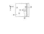
- FIG. 15 to 17 schematically show the positional relationship between the sample 42, the fluorescently labeled substance 44, and the cantilever 22 of the atomic force microscope close to the surface layer of the sample 42.
- FIG. 15 is a view seen from above the Z axis
- FIG. 16 is a view seen from the plus direction of the X axis in FIG.
- the sample 42 is a cell, for example, and the fluorescently labeled substance 44 is, for example, a fluorescently labeled virus, and the virus is scattered inside and outside the sample 42.
- the atomic force microscope acquires the surface layer information of the sample 42.
- the optical microscope performs fluorescence observation.
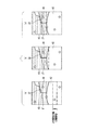
- the fluorescence observation the fluorescence information included in the Z resolution width (Z observation width) along the Z axis indicated by the one-dot chain line frame in FIGS. 17A, 17B, and 17C is acquired.
- the width of the Z resolution (Z observation width) can be freely set along the Z axis as shown in FIGS. 17A, 17B, and 17C, for example. For this reason, when the width of the Z resolution (Z observation width) is not in the surface layer of the sample 42, the fluorescence information in the vicinity of the surface layer of the sample 42 observed with the atomic force microscope cannot be obtained correctly.
- the main object of the present invention is to provide an observation method using a composite microscope that can obtain a correct positional correlation between fluorescence information and sample surface layer information.
- the present invention is an observation method using a composite microscope having an inverted optical microscope that performs at least fluorescence observation from below the sample and an atomic force microscope that acquires sample surface layer information from above the sample.
- the composite microscope has a Z-axis extending in the vertical direction.
- the inverted optical microscope includes a stage on which a transparent substrate holding a sample is placed, an objective lens disposed below the stage, and an objective lens driving actuator that drives the objective lens along the Z axis.
- the atomic force microscope includes a cantilever provided with a probe disposed above a stage at a free end, and a Z scanning actuator that scans the cantilever along the Z axis.
- the observation method using this composite microscope is that the cantilever is scanned along the Z-axis and the probe is brought close to the sample surface layer until the sample surface layer information can be acquired, and the cantilever is observed through an inverted optical microscope, at least the cantilever A cantilever observation step for acquiring the shape information of the probe, an observation position moving step for moving the observation position of the inverted optical microscope downward along the Z axis based on at least the length of the probe, and an inverted optical A fluorescence observation step of performing fluorescence observation through a microscope, and a sample surface layer information acquisition step of acquiring sample surface layer information by scanning the cantilever at least along the Z axis.
- the approach process, the cantilever observation process, and the observation position movement process are performed in order.
- the fluorescence observation process is performed after the observation position moving process.
- the sample surface information acquisition step is performed after the approach step.
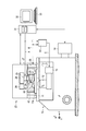
- FIG. 1 shows a composite microscope according to the first embodiment.
- FIG. 2 schematically shows the vicinity of the sample surface layer observed through a composite microscope.
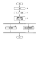
- FIG. 3 shows a process flow of the observation method of the first embodiment.
- FIG. 4 schematically shows the vicinity of the surface layer of the sample observed through the composite microscope shown in FIG.
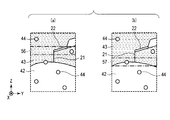
- FIG. 5 schematically shows the vicinity of the surface of the sample observed through the composite microscope shown in FIG. 1. The state where the cantilever is included in the width of the Z resolution (Z observation width) and the Z resolution A state in which the tip of the probe and the surface layer of the sample are included in the width (Z observation width) is shown.
- FIG. 6 shows a composite microscope according to the second embodiment.
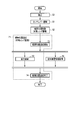
- FIG. 7 shows a process flow of the observation method of the second embodiment.
- FIG. 8 schematically shows the vicinity of the surface layer of the sample observed through the composite microscope shown in FIG. 6, and shows a state immediately after the observation position moving step and after a lapse of time.
- FIG. 9 shows a composite microscope according to the third embodiment.
- FIG. 10 shows a process flow of the observation method of the third embodiment.
- FIG. 11 shows a sample and its observation area.
- FIG. 12 shows a state in which fluorescence information and sample surface layer information are superimposed and displayed on a monitor.
- FIG. 13 shows a state in which fluorescence information and sample surface layer information are superimposed and displayed on the monitor using the cantilever shape information as a position reference.
- FIG. 14 schematically shows the vicinity of the sample surface layer observed through the composite microscope, and shows that the fluorescently labeled substance exists only at the bottom of the sample.
- FIG. 15 schematically shows a sample observed through a composite microscope.
- FIG. 16 schematically shows the vicinity of the sample surface layer observed through the composite microscope.
- FIG. 17 schematically shows the vicinity of the sample surface layer observed through the composite microscope and several positions of the width of Z resolution (Z observation width).
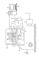
- FIG. 1 shows a composite microscope according to the present embodiment.
- the composite microscope shown in FIG. 1 includes an inverted optical microscope 10 that performs fluorescence observation in at least the sample 42 and the solution 43 from below the sample, and interatomic information that acquires information on the surface layer (sample surface layer information) of the sample 42 from above the sample.
- a force microscope 20 and a controller 31 for controlling the composite microscope are provided.
- the inverted optical microscope 10 is composed of either a confocal microscope or a super-resolution microscope.
- the composite microscope also includes a monitor 32 for displaying observation results and the like, and an input unit 33 for inputting instructions and the like.
- the composite microscope has an X axis, a Y axis, and a Z axis.
- the Z axis extends in the vertical direction, that is, the vertical direction, the X axis is orthogonal to the Z axis, and the Y axis is orthogonal to both the X axis and the Z axis.
- the inverted optical microscope 10 includes a stage 11 on which a transparent substrate 41 holding a sample 42 is placed, an objective lens 12 disposed below the stage 11, and an objective that drives the objective lens 12 along the Z axis.
- a lens driving actuator 13 and an imaging unit 14 such as a CCD camera are provided. More precisely, the stage 11 has a placement surface 11 a that contacts the substrate 41, and the objective lens 12 is disposed below the placement surface 11 a of the stage 11.
- the objective lens driving actuator 13 that drives the objective lens 12 along the Z axis is controlled by a controller 31, whereby the position of the width of the Z resolution (Z observation width) is set, for example, in FIGS. It can be set freely along the Z axis as shown in (c).
- the fluorescence information acquired by the inverted optical microscope 10 is, for example, information on a fluorescent substance such as a fluorescent dye such as a low molecular weight organic compound or a fluorescent protein such as GFP in cell observation. It is information that can be acquired by the inverted optical microscope 10 including information on autofluorescence.
- the inverted optical microscope 10 increases the resolution along the Z axis (hereinafter, Z resolution) by reducing light other than fluorescence emitted from the in-focus position.
- Z resolution the resolution along the Z axis
- a confocal microscope or a super solution such as STED or STORM An image microscope is used.
- the Z resolution of the confocal microscope is 500 nm to 1000 nm, and reaches a maximum of 100 nm or less in the super-resolution microscope.
- the atomic force microscope 20 is mounted on the inverted optical microscope 10.
- the atomic force microscope 20 includes a cantilever 22 provided with a probe 21 at a free end disposed above the stage 11, a Z piezoelectric element 25 for finely scanning the cantilever 22 along the Z axis, and the cantilever 22 with a Z axis.
- Z coarse actuator 26 is provided for coarse scanning along.
- the cantilever 22 is supported in a cantilever manner by a support body 23, and the support body 23 is attached to the Z piezoelectric element 25 by a holder 24.
- the Z piezoelectric element 25 and the Z coarse movement actuator 26 together constitute a Z scanning actuator 27 that scans the cantilever 22 along the Z axis.
- the atomic force microscope 20 also includes an XY scanning actuator 28 that scans the cantilever 22 along the X axis and the Y axis, and a displacement sensor 29 that detects the displacement of the cantilever 22.
- the tip of the probe 21 has a radius of curvature of 10 nm or less, which is so thin that it cannot be observed even with a super-resolution microscope.
- the Z piezoelectric element 25 and the XY scanning actuator 28 may be configured using, for example, a tube scanner, or may be configured using a scanning mechanism disclosed in Japanese Patent Application Laid-Open No. 2014-35252.
- the Z scanning actuator 27 is controlled by the controller 31 and causes the cantilever 22 to scan along the Z axis in accordance with a scanning signal (not shown) supplied from the controller 31.
- scanning the cantilever 22 along the Z-axis includes not only displacing the cantilever 22 dynamically or statically along the Z-axis, but also maintaining the cantilever 22 in a displaced state. .
- the Z scanning actuator 27 scans the cantilever 22 along the Z axis in accordance with the Z scanning signal supplied from the controller 31, thereby causing the Z scanning actuator 27 to move along the Z axis between the tip of the probe 21 and the surface layer of the sample 42. Can change the distance. The distance can also be maintained.
- the displacement sensor 29 outputs a displacement signal indicating the displacement of the cantilever 22 to the controller 31.
- the controller 31 acquires sample surface layer information based on the input displacement signal.
- the sample surface layer information acquired by the atomic force microscope 20 is information on physical interaction that occurs between the sample and the probe, such as the uneven shape of the sample, viscoelasticity information, and electrical information.
- the information on the concavo-convex shape of the sample is image information of the sample surface layer obtained by performing XY scanning and Z scanning of the cantilever 22, and viscoelasticity information is obtained by performing only Z scanning without causing the cantilever 22 to perform XY scanning. This is the mechanical information obtained between the probe 21 and the sample 42.
- the transparent substrate 41 holding the sample 42 is placed on the stage 11 of the inverted optical microscope 10.
- the stage 11 has an XY stage (not shown), and the substrate 41 is placed on the XY stage.
- the sample 42, the probe 21 and the cantilever 22 are surrounded by a solution 43 held on the substrate 41.
- FIG. 2 schematically shows a view of the vicinity of the surface of the sample observed through the composite microscope as seen from the X-axis plus direction.
- the sample 42 is, for example, a living cell
- the fluorescently labeled substance 44 is, for example, a fluorescently labeled virus, which is scattered inside and outside the cell.
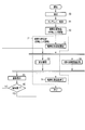
- FIG. 3 shows a process flow of the observation method of the present embodiment.
- 4 and 5 schematically show the vicinity of the sample surface layer observed through the composite microscope.
- the Z scanning actuator 27 is expanded and contracted, more specifically, the Z piezoelectric element 25 constituting the Z scanning actuator 27 is extended, or the Z coarse actuator 26 is contracted, or both.
- the cantilever 22 is scanned along the Z-axis, and as shown in FIG. 4, until the interaction between the tip of the probe 21 and the surface of the sample 42 occurs, that is, until the sample surface information can be acquired. The tip is brought close to the surface layer of the sample 42.
- the cantilever 22 is observed through the inverted optical microscope 10, and the shape information of the cantilever 22 is acquired. Desirably, the root portion of the probe 21 is observed, and the shape information of the root portion of the cantilever 22 is acquired.
- the cantilever 22 is observed by fluorescence observation of autofluorescence of the cantilever 22 or by bright field observation.
- the objective lens 12 is driven along the Z axis by the objective lens driving actuator 13, and the position of the Z resolution width (Z observation width) along the Z axis is shown in FIG. The position is set at the position of the Z resolution width (Z observation width) 56.
- the cantilever 22 is included in the Z resolution width (Z observation width) 56.
- the observation position of the inverted optical microscope 10 that is, the position of the Z resolution width (Z observation width) is based on at least the length of the probe 21, for example, the same as the length of the probe 21.
- the sample 42 is moved in the downward direction along the Z axis by the distance.
- the position of the Z resolution width (Z observation width) is set to the position of the Z resolution width (Z observation width) 57 shown in FIG.
- the Z resolution width (Z observation width) 57 includes the tip of the probe 21 and the surface layer of the sample 42.
- the position of the Z resolution width (Z observation width) 57 is moved by driving the objective lens 12 by the objective lens driving actuator 13.
- the driving amount may be set simply based on the length of the probe 21, but preferably the length of the probe 21, the refractive index of the solution 43, and the case where an oil immersion objective lens is used as the objective lens 12. Is set based on the refractive index of the immersion oil.
- the objective lens 12 can be driven by a method of driving the entire unit including the exterior of the objective lens 12 or a method of driving at least one lens inside the objective lens 12.
- an immersion objective lens such as an oil immersion objective lens, a water immersion objective lens, or a silicone immersion objective lens
- the sample 42 is placed via the liquid. Since there is a possibility that vibration noise is generated in the substrate 41, a method of driving at least one lens inside the objective lens 12 is desirable. In this method, since the exterior of the objective lens 12 does not move, the influence of vibration noise on the substrate 41 is reduced. Further, a configuration of a microscope capable of moving the focal point without changing the distance between the objective lens and the sample disclosed in Japanese Patent Application Laid-Open No. 2005-10516 may be used.
- the position of the Z resolution width (Z observation width) can be set on the surface layer of the sample 42 as shown in FIG.
- a fluorescence observation step 53 and a sample surface layer information acquisition step 54 are performed.
- the fluorescence in the sample 42 and the solution 43 is observed through the inverted optical microscope 10.
- the atomic force microscope 20 scans at least the cantilever 22 along the Z axis, and acquires the surface layer information of the sample 42 as the sample surface layer information.
- the fluorescence observation step 53 and the sample surface layer information acquisition step 54 may be performed in order, but are desirably performed simultaneously when it is desired to obtain a positional correlation with a change in time.
- the start of the sample surface layer information acquisition step 54 is not limited to after the observation position moving step 52.
- the start of the sample surface layer information acquisition step 54 may be immediately after the approach step 50 if it does not interfere with the roles of the cantilever observation step 51 and the observation position movement step 52.
- the approaching step 50, the cantilever observation step 51, and the observation position moving step 52 are performed in order, and the fluorescence observation step 53 is performed after the approaching step 50, the cantilever observation step 51, and the observation position moving step 52 are performed in order.
- the information acquisition process 54 is performed after the approach process 50.
- the sample surface layer information acquiring step 54 is desirably performed after the observation position moving step 52.
- a program for executing this observation method is installed in the controller 31.
- the fluorescence information in the vicinity of the surface layer of the sample 42 for acquiring the surface layer information with the atomic force microscope 20 is obtained correctly, and as a result, the correct positional correlation between the sample surface layer information and the fluorescence information is obtained. It becomes possible to obtain.
- the radius of curvature of the probe tip is 10 nm or less, and the tip of the probe is so thin that it cannot be observed even with a super-resolution microscope.
- the cantilever 22 is observed by a cantilever observation step 51 and finally the position of the Z resolution width (Z observation width) of the inverted optical microscope 10 is determined by the probe 21 by an observation position moving step 52. By moving based on the length, the position of the width of Z resolution (Z observation width) is set on the surface layer of the sample 42.
- use of the cantilever 22, preferably the root portion of the probe 21 of the cantilever 22, provides the highest accuracy.
- FIG. 6 shows the composite microscope according to the present embodiment.
- members denoted by the same reference numerals as those shown in FIG. 1 are similar members, and detailed description thereof is omitted.
- the tracking control controller 60 is added to the composite microscope shown in FIG. 1 in the composite microscope shown in FIG.
- the fine movement scanning signal A output from the controller 31 is supplied to the Z piezoelectric element 25, and the coarse movement scanning signal B output from the controller 31 is supplied to the Z coarse movement actuator 26.
- the scanning signal composed of both the scanning signal A and the scanning signal B output from the controller 31 is supplied to the Z scanning actuator 27 including the Z piezoelectric element 25 and the Z coarse actuator 26.
- the Z scanning actuator 27 is controlled by the controller 31 and causes the cantilever 22 to scan along the Z axis in accordance with a scanning signal supplied from the controller 31.
- scanning the cantilever 22 along the Z-axis includes not only displacing the cantilever 22 dynamically or statically along the Z-axis, but also maintaining the cantilever 22 in a displaced state. .
- the Z scanning actuator 27 scans the cantilever 22 along the Z axis in accordance with the scanning signal supplied from the controller 31, thereby changing the distance along the Z axis between the tip of the probe 21 and the surface of the sample 42. be able to. The distance can also be maintained.
- the scanning signal A and the scanning signal B supplied to the Z piezoelectric element 25 and the Z coarse movement actuator 26, in other words, the scanning signal supplied to the Z scanning actuator 27 are also supplied to the follow-up control controller 60.
- the tracking control controller 60 controls the objective lens driving actuator 13 so that the objective lens 12 is driven following the scanning along the Z axis of the cantilever 22.
- the follow-up control controller 60 controls the objective lens driving actuator 13 based on the scanning signal composed of the scanning signal A and the scanning signal B.
- the follow-up controller 60 generates a drive signal C based on the scan signal composed of the scan signal A and the scan signal B, and supplies the drive signal C to the objective lens drive actuator 13.
- the tracking controller 60 first obtains the expansion / contraction amounts of the Z piezoelectric element 25 and the Z coarse movement actuator 26 from the supplied scanning signal A and scanning signal B, respectively. Next, the amount of displacement along the Z-axis of the cantilever 22 is obtained based on the amount of expansion / contraction of the Z piezoelectric element 25 and the amount of expansion / contraction of the Z coarse actuator 26. Further, the driving amount of the objective lens 12 is obtained from the displacement amount along the Z axis of the cantilever 22. Then, a drive signal C is generated based on the displacement amount and supplied to the objective lens drive actuator 13.
- the driving amount of the objective lens driving actuator 13 is obtained based on the length of the probe 21, the refractive index of the sample 42, or the immersion oil refractive index when an oil immersion objective lens is used as the objective lens 12.
- a displacement sensor may be provided in the Z scanning actuator 27, and the objective lens driving actuator 13 may be controlled based on information on the scanning amount of the Z scanning actuator 27 (equivalent to the displacement amount of the cantilever 22) obtained by the displacement sensor.
- tracking control controller 60 may be built in the controller 31 of the composite microscope.
- FIG. 7 shows a process flow of the observation method of the present embodiment.
- the observation method of this embodiment has an observation position tracking step 71 in addition to the steps of the observation method shown in FIG. 3 described in the first embodiment.
- the observation position tracking process 71 has an observation position tracking start process 72, a fluorescence observation process 53, and an observation position tracking end process 74. That is, the observation position tracking step 71 includes a fluorescence observation step 53.
- the observation position tracking step 71 the observation position along the Z axis of the inverted optical microscope 10 is moved following the scanning along the Z axis of the cantilever 22.
- the objective lens driving actuator 13 drives the objective lens 12 so that the objective lens 12 follows scanning along the Z axis of the cantilever 22.
- FIG. 8A shows a state immediately after the observation position moving step 52.
- the observation position tracking process 71 is started between the observation position moving process 52 and the fluorescence observation process 53. That is, an observation position tracking start process 72 is performed between the observation position moving process 52 and the fluorescence observation process 53.
- the sample surface layer information acquisition step 54 and the fluorescence observation step 53 are started.
- the atomic force microscope 20 scans at least the cantilever 22 along the Z axis, and acquires the surface layer information of the sample 42 as the sample surface layer information.
- the fluorescence in the sample 42 and the solution 43 is observed through the inverted optical microscope 10.
- sample surface layer information acquisition step 54 and the fluorescence observation step 53 are performed simultaneously when it is desired to obtain a positional correlation with time change.
- the start of the sample surface layer information acquisition step 54 is not limited to after the observation position moving step 52.
- the start of the sample surface layer information acquisition step 54 may be immediately after the approach step 50 if it does not interfere with the roles of the cantilever observation step 51 and the observation position movement step 52.
- the observation position tracking step 71 is finished. That is, the observation position tracking end step 74 is performed.
- a program for executing this observation method is installed in the controller 31.
- this embodiment has the following effects. For example, when the sample 42 is a living cell and the position of the surface layer along the Z axis changes from (a) to (b) and (c) in FIG. If 71 is not performed, the fluorescence information near the surface layer of the sample 42 cannot be obtained correctly. On the other hand, in this embodiment, since the observation position follow-up step 71 is performed, the position along the Z axis of the surface layer of the sample 42 changes with time exceeding the Z resolution width (Z observation width) 57. Even in this case, fluorescence information in the vicinity of the surface layer of the sample 42 can be obtained correctly.
- FIG. 9 shows the composite microscope according to the present embodiment. 9, members denoted by the same reference numerals as those shown in FIG. 6 are similar members, and detailed description thereof is omitted.
- the composite microscope of this embodiment is different from the composite microscope of the second embodiment shown in FIG. 6 only in the controller.
- the composite microscope of this embodiment shown in FIG. 9 includes a controller 34 instead of the controller 31 of the second embodiment.
- the controller 34 performs image processing for superimposing the sample surface layer information and the fluorescence information.
- the monitor 32 displays an image in which the sample surface layer information and the fluorescence information are superimposed.
- FIG. 10 shows a process flow of the observation method of the present embodiment.
- the observation method of this embodiment has an image display step 81 and an observation end step 82 in addition to the steps of the observation method shown in FIG. 7 described in the second embodiment.
- the sample surface layer information acquired in the sample surface layer information acquisition step 54 and the fluorescence information acquired in the fluorescence observation step 53 are superimposed and displayed on the monitor 32.
- the image display process 81 is performed after the sample surface information acquisition process 54 and the fluorescence observation process 53 are completed and before the observation position tracking completion process 74.
- the information acquired in the sample surface layer information acquisition step 54 and the fluorescence observation step 53 may be any unit, for example, in units of lines, images, or moving images. In the present embodiment, each information Will be described as an image unit.
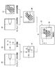
- the image display step 81 for example, as shown in FIG. 11, when an area 91 of the sample 90 is observed, an image in which the fluorescence information 92 and the sample surface layer information 93 are superimposed on the monitor 32 as shown in FIG. 94 is displayed.
- the fluorescence information 92 and the sample surface layer information 93 are obtained using the shape information 95 of the cantilever 22 acquired in the cantilever observation step 51 as a position reference in the XY plane perpendicular to the Z axis.
- the images may be superimposed and displayed on the monitor 32.
- the reference information 97 of the fluorescence information 92 is determined by superimposing the shape information 95 of the cantilever 22 and the fluorescence information 92
- the reference of the sample surface information 93 is superimposed by superimposing the shape information 95 of the cantilever 22 and the sample surface information 93.
- the position 96 may be determined, and a superimposed image of the fluorescence information 92 and the sample surface layer information 93 may be generated using the reference position 97 and the reference position 96 and displayed on the monitor 32.
- observation end step 82 it is determined whether or not the observation is ended. If the observation is not completed, the process returns to the fluorescence observation step 53 and the sample surface layer information acquisition step 54. If the observation is completed, the process proceeds to an observation position tracking end process 74.
- a program for executing this observation method is installed in the controller 34.
- the fluorescence information 92 and the sample surface information 93 are displayed in an overlapping manner, the positional correlation between the sample surface information and the fluorescence information can be obtained with higher accuracy.
- the effect is not limited to the case where the fluorescently labeled substance 44 exists both inside and outside the sample 42 as shown in FIG. In the present invention, even when the fluorescently labeled substance 44 exists only inside the sample 42, the same effect can be obtained.
- the inverted optical system is not used in accordance with the present invention.
- the microscope 10 tries to acquire the fluorescence information, the microscope 10 necessarily acquires the fluorescence information of the bottom of the sample 42. That is, the inverted optical microscope 10 acquires fluorescence information at a position along the Z-axis that is greatly deviated from the surface layer of the sample 42 observed by the atomic force microscope 20 (so as not to discuss the positional correlation). become.
- the fluorescence information to be acquired at this time is that “the fluorescently labeled substance 44 is not present on the sample surface layer”, which is correct fluorescence information.
- this conventional fluorescence microscope cannot acquire this correct fluorescence information.
- the most important problem is that the conventional composite microscope cannot recognize that fluorescence information at a position along the Z axis that is greatly displaced is acquired.
- the position of the Z resolution width (Z observation width) of the inverted optical microscope 10 is adjusted to the surface layer of the sample 42 regardless of the presence or absence of the fluorescently labeled substance 44. Therefore, the present invention can solve such a problem.
- the effect is not limited to the case where the sample 42 is present in the solution 43.
- the above-described “in the case where the fluorescently labeled substance 44 exists only inside the sample 42” is effective even when the sample 42 exists in the atmosphere.
Landscapes
- Physics & Mathematics (AREA)
- General Physics & Mathematics (AREA)
- Chemical & Material Sciences (AREA)
- Analytical Chemistry (AREA)
- Optics & Photonics (AREA)
- Health & Medical Sciences (AREA)
- General Health & Medical Sciences (AREA)
- Nuclear Medicine, Radiotherapy & Molecular Imaging (AREA)
- Radiology & Medical Imaging (AREA)
- Multimedia (AREA)
- Engineering & Computer Science (AREA)
- Life Sciences & Earth Sciences (AREA)
- Biochemistry (AREA)
- Immunology (AREA)
- Pathology (AREA)
- Microscoopes, Condenser (AREA)
- Investigating, Analyzing Materials By Fluorescence Or Luminescence (AREA)
Abstract
倒立型光学顕微鏡と原子間力顕微鏡の複合型顕微鏡による観察方法は、カンチレバーをZ軸に沿って走査させて、試料表層情報が取得できるまで探針を試料表層に近づける接近工程(50)と、倒立型光学顕微鏡を通してカンチレバーを観察し、少なくともカンチレバーの形状情報を取得するカンチレバー観察工程(51)と、倒立型光学顕微鏡の観察位置を、少なくとも探針の長さに基づいて、Z軸に沿って下方に向けて移動させる観察位置移動工程(52)と、倒立型光学顕微鏡を通して蛍光観察を行う蛍光観察工程(53)と、カンチレバーを少なくともZ軸に沿って走査させて試料表層情報を取得する試料表層情報取得工程(54)を有する。接近工程とカンチレバー観察工程と観察位置移動工程は順に行う。蛍光観察工程は観察位置移動工程の後に行う。試料表層情報取得工程は、接近工程(50)の後に行う。
Description
本発明は、倒立型光学顕微鏡と原子間力顕微鏡を有する複合型顕微鏡による観察方法に関する。
複合型顕微鏡とは、互いに異なる物理情報を取得する少なくとも2種類の顕微鏡を組み合わせた顕微鏡システムである。その代表例として、蛍光観察を行う光学顕微鏡と試料表層の微細な形状を観察する原子間力顕微鏡を組み合わせた複合型顕微鏡がある。この複合型顕微鏡は、同一試料の蛍光情報と試料表層情報の時空間的な相関を得ることができるという利点を有する。
このような複合顕微鏡の光学顕微鏡には、合焦位置から発せられる蛍光以外の光を低減することでZ軸に沿った分解能(以下、Z分解能)が高められた例えば共焦点顕微鏡やSTEDやSTORMなどの超解像顕微鏡が用いられることがある。共焦点顕微鏡のZ分解能は、500nm~1000nmであり、超解像顕微鏡にいたっては近年では100nm以下まで実現できている。
このような複合型顕微鏡の従来例は、例えば、Impact of Actin Rearrangement and Degranulation on the Membrane Structure of Primary Mast Cells: A Combined Atomic Force and Laser Scanning Confocal Microscopy Investigation (Biophysical Journal Volume 96 February 2009 1629-1639)に開示されている。
上記従来例においては、蛍光標識された物質が試料内部にのみ存在している試料(細胞)を観察している。しかし、蛍光標識された物質が試料の内部と外部の両方に存在する場合は、光学顕微鏡の観察像すなわち蛍光情報と原子間力顕微鏡の観察像すなわち試料表層情報の位置相関が正しく得られないことがある。
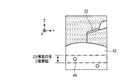
図15~図17は、試料42と、蛍光標識された物質44と、試料42の表層に近接した原子間力顕微鏡のカンチレバー22の位置関係を模式的に示している。図15は、Z軸上方から見た図であり、また図16は、図15のX軸プラス方向から見た図である。
図15~図17において、試料42は、例えば細胞であり、蛍光標識された物質44は、例えば蛍光標識されたウイルスであり、ウイルスが試料42の内外に点在しているとする。
原子間力顕微鏡は、試料42の表層情報を取得する。それに対して、光学顕微鏡は、蛍光観察を行う。蛍光観察では、図17の(a)、(b)、(c)の一点鎖線枠で示すZ軸に沿ったZ分解能の幅(Z観察幅)に含まれている蛍光情報を取得する。光学顕微鏡では、Z分解能の幅(Z観察幅)を、例えば図17の(a)、(b)、(c)に示されるように、Z軸に沿って自由に設定できてしまう。このため、Z分解能の幅(Z観察幅)が試料42の表層にない場合には、原子間力顕微鏡で観察している試料42の表層付近の蛍光情報が正しく得られない、すなわち原子間力顕微鏡の試料表層情報と光学顕微鏡の蛍光情報の正しい位置相関が得られないという問題がある。さらに共焦点顕微鏡や超解像顕微鏡などのZ分解能が高い光学顕微鏡においては、正しい位置相関を得ることがより困難になる。
本発明の主な目的は、蛍光情報と試料表層情報の正しい位置相関が得られる複合型顕微鏡による観察方法を提供することである。
本発明は、ひとつのアスペクトにおいては、試料下方から少なくとも蛍光観察を行う倒立型光学顕微鏡と、試料上方から試料表層情報を取得する原子間力顕微鏡とを有する複合型顕微鏡による観察方法である。複合型顕微鏡は、上下方向に延びるZ軸を有している。倒立型光学顕微鏡は、試料を保持した透明な基板が載置されるステージと、ステージの下方に配置された対物レンズと、Z軸に沿って対物レンズを駆動する対物レンズ駆動アクチュエータを備えている。原子間力顕微鏡は、ステージの上方に配置される探針を自由端に備えたカンチレバーと、カンチレバーをZ軸に沿って走査させるZ走査アクチュエータを備えている。この複合型顕微鏡による観察方法は、カンチレバーをZ軸に沿って走査させて、試料表層情報が取得できるまで探針を試料表層に近づける接近工程と、倒立型光学顕微鏡を通してカンチレバーを観察し、少なくともカンチレバーの形状情報を取得するカンチレバー観察工程と、倒立型光学顕微鏡の観察位置を、少なくとも探針の長さに基づいて、Z軸に沿って下方に向けて移動させる観察位置移動工程と、倒立型光学顕微鏡を通して蛍光観察を行う蛍光観察工程と、カンチレバーを少なくともZ軸に沿って走査させて試料表層情報を取得する試料表層情報取得工程を有する。接近工程とカンチレバー観察工程と観察位置移動工程は順に行う。蛍光観察工程は観察位置移動工程の後に行う。試料表層情報取得工程は、接近工程の後に行う。
本発明によれば、試料表層情報と蛍光情報の正しい位置相関を得ることが可能になる。
<第一の実施形態>
第一の実施形態について、図1~図5を用いて以下に説明する。図1は、本実施形態による複合型顕微鏡を示している。
第一の実施形態について、図1~図5を用いて以下に説明する。図1は、本実施形態による複合型顕微鏡を示している。
図1に示す複合型顕微鏡は、試料下方から少なくとも試料42および溶液43内の蛍光観察を行う倒立型光学顕微鏡10と、試料上方から試料42の表層の情報(試料表層情報)を取得する原子間力顕微鏡20と、複合型顕微鏡を制御するコントローラ31とを備えている。倒立型光学顕微鏡10は、共焦点顕微鏡と超解像顕微鏡のいずれかで構成されている。複合型顕微鏡はまた、観察結果の表示等を行うためなどのモニター32と、指示の入力等を行うための入力部33を備えている。
複合型顕微鏡はX軸とY軸とZ軸を有している。Z軸は上下方向すなわち鉛直方向に延びており、X軸はZ軸に直交しており、Y軸はX軸とZ軸の両方に直交している。
倒立型光学顕微鏡10は、試料42を保持した透明な基板41が載置されるステージ11と、ステージ11の下方に配置された対物レンズ12と、Z軸に沿って対物レンズ12を駆動する対物レンズ駆動アクチュエータ13と、例えばCCDカメラなどの撮像ユニット14とを備えている。より正確には、ステージ11は基板41と接触する載置面11aを有しており、対物レンズ12はステージ11の載置面11aの下方に配置されている。
対物レンズ12をZ軸に沿って駆動する対物レンズ駆動アクチュエータ13はコントローラ31により制御され、それによりZ分解能の幅(Z観察幅)の位置を、例えば図17の(a)、(b)、(c)のようにZ軸に沿って自由に設定し得る。
倒立型光学顕微鏡10で取得する蛍光情報とは、例えば、細胞の観察においては、低分子有機化合物の蛍光色素や、GFP等の蛍光タンパク質などの、蛍光物質の情報であり、また、ケージド化合物や自家蛍光の情報を含む、倒立型光学顕微鏡10で取得可能な情報のことである。
倒立型光学顕微鏡10は、合焦位置から発せられる蛍光以外の光を低減することでZ軸に沿った分解能(以下、Z分解能)を高くした、例えば共焦点顕微鏡またはSTEDやSTORMなどの超解像顕微鏡が用いられる。共焦点顕微鏡のZ分解能は500nm~1000nmであり、超解像顕微鏡においては最高で100nm以下に達している。
原子間力顕微鏡20は、倒立型光学顕微鏡10の上に搭載されている。原子間力顕微鏡20は、ステージ11の上方に配置される自由端に探針21を備えたカンチレバー22と、カンチレバー22をZ軸に沿って微動走査させるZ圧電素子25と、カンチレバー22をZ軸に沿って粗動走査させるZ粗動アクチュエータ26を備えている。カンチレバー22は支持体23によって片持ちに支持されており、支持体23はホルダ24によってZ圧電素子25に取り付けられている。Z圧電素子25とZ粗動アクチュエータ26は、それら両方でカンチレバー22をZ軸に沿って走査させるZ走査アクチュエータ27を構成している。原子間力顕微鏡20はまた、カンチレバー22をX軸とY軸に沿って走査させるXY走査アクチュエータ28と、カンチレバー22の変位を検出する変位センサ29を備えている。
探針21の先端はその曲率半径が10nm以下であり、これは超解像顕微鏡であっても観察できないほど細い。
Z圧電素子25とXY走査アクチュエータ28は、例えば、チューブスキャナを用いて構成されてもよいし、特開2014-35252号公報の走査機構を用いて構成されてもよい。
Z走査アクチュエータ27は、コントローラ31により制御され、コントローラ31から供給される図示しない走査信号に応じてカンチレバー22をZ軸に沿って走査させる。
ここでカンチレバー22をZ軸に沿って走査させるとは、カンチレバー22をZ軸に沿って動的にあるいは静的に変位させるだけでなく、カンチレバー22を変位した状態に維持することも含んでいる。
従ってZ走査アクチュエータ27は、コントローラ31から供給されるZ走査信号に応じてカンチレバー22をZ軸に沿って走査させ、それにより探針21の先端と試料42の表層との間のZ軸に沿った距離を変えることができる。またその距離を維持することもできる。
変位センサ29は、カンチレバー22の変位を示す変位信号をコントローラ31に出力する。コントローラ31は、入力される変位信号に基づいて試料表層情報を取得する。
原子間力顕微鏡20で取得する試料表層情報とは、例えば、試料の凹凸形状、粘弾性情報、電気的情報などの、試料と探針間に生じる物理的相互作用の情報である。例えば、試料の凹凸形状の情報は、カンチレバー22をXY走査およびZ走査させることによって得られる試料表層の画像情報であり、また粘弾性情報は、カンチレバー22をXY走査させずに、Z走査のみによって得られる、探針21と試料42の間に働く力学的な情報である。
試料42を保持した透明な基板41は、倒立型光学顕微鏡10のステージ11の上に載置される。例えば、ステージ11は図示しないXYステージを有しており、基板41は、このXYステージの上に載置される。試料42と探針21とカンチレバー22は、基板41に保持された溶液43によって包囲される。
図2は、複合型顕微鏡を通して観察される試料表層付近をX軸プラス方向から見た図を模式的に示している。試料42は、例えば、生細胞であり、蛍光標識された物質44は、例えば、蛍光標識されたウイルスであり、細胞内外に点在しているものとする。
次に、このように構成された本実施形態の複合型顕微鏡の動作の流れ(観察方法の工程)を図3ないし図5を用いて説明する。図3は、本実施形態の観察方法の工程フローを示している。図4と図5は、複合型顕微鏡を通して観察される試料表層付近を模式的に示している。
接近工程50では、Z走査アクチュエータ27を伸縮動作させることにより、詳しくは、Z走査アクチュエータ27を構成するZ圧電素子25を伸ばすことにより、あるいはZ粗動アクチュエータ26を縮めることにより、またはその両方により、カンチレバー22をZ軸に沿って走査させて、図4に示すように、探針21の先端と試料42の表層の相互作用が生じるまで、すなわち試料表層情報が取得できるまで、探針21の先端を試料42の表層に近づける。
次のカンチレバー観察工程51では、倒立型光学顕微鏡10を通してカンチレバー22を観察し、カンチレバー22の形状情報を取得する。望ましくは探針21の根元部分を観察し、カンチレバー22の根元部分の形状情報を取得する。このカンチレバー観察工程51では、カンチレバー22の自家蛍光の蛍光観察によって、あるいは明視野観察によってカンチレバー22を観察する。このカンチレバー観察工程51では、対物レンズ駆動アクチュエータ13により対物レンズ12をZ軸に沿って駆動し、Z分解能の幅(Z観察幅)のZ軸に沿った位置を図5の(a)に示すZ分解能の幅(Z観察幅)56の位置に設定する。Z分解能の幅(Z観察幅)56内にはカンチレバー22が含まれている。
次の観察位置移動工程52では、倒立型光学顕微鏡10の観察位置すなわちZ分解能の幅(Z観察幅)の位置を、少なくとも探針21の長さに基づいて、例えば探針21の長さと同じ距離だけ、Z軸に沿って試料42の下方の向きに移動させる。これにより、Z分解能の幅(Z観察幅)の位置は、図5の(b)に示すZ分解能の幅(Z観察幅)57の位置に設定される。Z分解能の幅(Z観察幅)57内には探針21の先端と試料42の表層が含まれている。
この観察位置移動工程52においては、Z分解能の幅(Z観察幅)57の位置の移動は、対物レンズ駆動アクチュエータ13により対物レンズ12を駆動することで行う。その駆動量は、単に探針21の長さに基づいて設定されてよいが、好ましくは、探針21の長さや、溶液43の屈折率や、対物レンズ12として油浸対物レンズを使用する場合はイマージョンオイルの屈折率などに基づいて設定される。
なお、対物レンズ12の駆動には、対物レンズ12の外装を含めたユニット全体を駆動する方法と、対物レンズ12の内部にある少なくともひとつのレンズを駆動する方法がある。油侵対物レンズ、水侵対物レンズ、またはシリコーン侵対物レンズなどの液浸対物レンズを使う場合は、対物レンズ12のユニット全体を駆動すると、その動作が液体を介して試料42が載置された基板41に振動ノイズを生じさせる可能性があるため、対物レンズ12の内部にある少なくともひとつのレンズを駆動する方法が望ましい。この方法においては、対物レンズ12の外装が動かないため、基板41への振動ノイズの影響が低減される。また、特開2005-10516号公報に開示された対物レンズと試料の距離を変えないで焦点移動が可能な顕微鏡の構成を用いても構わない。
以上の3つの工程により、Z分解能の幅(Z観察幅)の位置を、図5の(b)に示すように試料42の表層に設定することができる。
その後、蛍光観察工程53と試料表層情報取得工程54を行う。
蛍光観察工程53では、倒立型光学顕微鏡10を通して、試料42および溶液43内の蛍光観察を行う。
試料表層情報取得工程54では、原子間力顕微鏡20により、少なくともカンチレバー22をZ軸に沿って走査させて、試料表層情報である試料42の表層の情報を取得する。
蛍光観察工程53と試料表層情報取得工程54は、順に行ってもよいが、時間変化を伴う位置相関を得たい場合は同時に行うことが望ましい。
なお、試料表層情報取得工程54の開始は、観察位置移動工程52の後に限らない。例えば、試料表層情報取得工程54の開始は、カンチレバー観察工程51および観察位置移動工程52の役割を妨げない場合は、接近工程50の直後であってもよい。
すなわち、接近工程50とカンチレバー観察工程51と観察位置移動工程52は順に行い、蛍光観察工程53は、接近工程50とカンチレバー観察工程51と観察位置移動工程52を順に行った後に行うが、試料表層情報取得工程54は、接近工程50の後に行う。試料表層情報取得工程54は、望ましくは観察位置移動工程52の後に行う。
以上の工程を行うため、この観察方法を実行するプログラムがコントローラ31にインストールされている。
本実施形態の観察方法を実施することにより、原子間力顕微鏡20で表層情報を取得する試料42の表層近傍の蛍光情報が正しく得られ、その結果、試料表層情報と蛍光情報の正しい位置相関を得ることが可能になる。
本実施形態においては、探針先端の曲率半径が10nm以下であり、探針先端が超解像顕微鏡であっても観察できないほど細いために、まず接近工程50により探針21の先端を試料42の表層に近づけて、その次にカンチレバー観察工程51によりカンチレバー22を観察し、最後に観察位置移動工程52により倒立型光学顕微鏡10のZ分解能の幅(Z観察幅)の位置を探針21の長さに基づいて移動させることにより、Z分解能の幅(Z観察幅)の位置を試料42の表層に設定している。
Z分解能の幅(Z観察幅)の位置の基準としては、カンチレバー22、望ましくはカンチレバー22の探針21の根元部分を用いるのが最も精度が高くなる。
<第二の実施形態>
以下、図6~図8を参照しながら本実施形態について説明する。図6は、本実施形態による複合型顕微鏡を示している。図6において、図1に示した部材と同一の参照符号を付した部材は同様の部材であり、その詳しい説明は省略する。
以下、図6~図8を参照しながら本実施形態について説明する。図6は、本実施形態による複合型顕微鏡を示している。図6において、図1に示した部材と同一の参照符号を付した部材は同様の部材であり、その詳しい説明は省略する。
図6に示す複合型顕微鏡は、図1に示す複合型顕微鏡に対して、追従制御コントローラ60が追加されている。
コントローラ31から出力される微動用の走査信号Aは、Z圧電素子25に供給され、コントローラ31から出力される粗動用の走査信号Bは、Z粗動アクチュエータ26に供給される。言い換えると、コントローラ31から出力される走査信号Aと走査信号Bの両方から成る走査信号が、Z圧電素子25とZ粗動アクチュエータ26で構成されるZ走査アクチュエータ27に供給される。
Z走査アクチュエータ27は、コントローラ31により制御され、コントローラ31から供給される走査信号に応じてカンチレバー22をZ軸に沿って走査させる。
ここでカンチレバー22をZ軸に沿って走査させるとは、カンチレバー22をZ軸に沿って動的にあるいは静的に変位させるだけでなく、カンチレバー22を変位した状態に維持することも含んでいる。
従ってZ走査アクチュエータ27は、コントローラ31から供給される走査信号に応じてカンチレバー22をZ軸に沿って走査させ、それにより探針21の先端と試料42の表層のZ軸に沿った距離を変えることができる。またその距離を維持することもできる。
Z圧電素子25とZ粗動アクチュエータ26にそれぞれ供給される走査信号Aと走査信号Bは、言い換えるとZ走査アクチュエータ27に供給される走査信号は、追従制御コントローラ60にも供給される。
追従制御コントローラ60は、対物レンズ12がカンチレバー22のZ軸に沿った走査に追従して駆動されるよう対物レンズ駆動アクチュエータ13を制御するものである。
詳しくは、追従制御コントローラ60は、走査信号Aと走査信号Bから成る走査信号に基づいて対物レンズ駆動アクチュエータ13を制御するものである。
この追従制御コントローラ60は、走査信号Aと走査信号Bから成る走査信号に基づいて駆動信号Cを生成し、駆動信号Cを対物レンズ駆動アクチュエータ13に供給する。
詳しくは、追従制御コントローラ60は、まず、供給される走査信号Aと走査信号BからZ圧電素子25とZ粗動アクチュエータ26の伸縮量をそれぞれ求める。次にZ圧電素子25の伸縮量とZ粗動アクチュエータ26の伸縮量に基づいてカンチレバー22のZ軸に沿った変位量を求める。さらにカンチレバー22のZ軸に沿った変位量から対物レンズ12の駆動量を求める。そして、その変位量に基づき駆動信号Cを生成し、対物レンズ駆動アクチュエータ13に供給する。
対物レンズ駆動アクチュエータ13の駆動量は、探針21の長さや、試料42の屈折率や、対物レンズ12として油浸対物レンズを使用する場合はイマージョンオイルの屈折率などに基づいて求められる。
なお、追従制御コントローラ60が走査信号に基づいて対物レンズ駆動アクチュエータ13を制御する以外に、様々な変形が考えられる。例えば、Z走査アクチュエータ27に変位センサを設け、変位センサで得られるZ走査アクチュエータ27の走査量(カンチレバー22の変位量と同等)の情報に基づいて対物レンズ駆動アクチュエータ13を制御してもよい。
また、追従制御コントローラ60は、複合型顕微鏡のコントローラ31に内蔵されていてもよい。
図7は、本実施形態の観察方法の工程フローを示している。本実施形態の観察方法は、第一の実施形態で説明した図3に示す観察方法の工程に加えて、観察位置追従工程71を有している。
観察位置追従工程71は、観察位置追従開始工程72と蛍光観察工程53と観察位置追従終了工程74を有している。すなわち観察位置追従工程71は、蛍光観察工程53を含んでいる。
観察位置追従工程71では、倒立型光学顕微鏡10のZ軸に沿った観察位置をカンチレバー22のZ軸に沿った走査に追従して移動させる。言い換えると、対物レンズ駆動アクチュエータ13は、対物レンズ12がカンチレバー22のZ軸に沿った走査に追従するように対物レンズ12を駆動する。
本実施形態の観察方法は、第一の実施形態で説明した図3の観察位置移動工程52に続いて以下の工程を行う。図8の(a)は、観察位置移動工程52の直後の状態を示す。
観察位置移動工程52と蛍光観察工程53の間に観察位置追従工程71を開始する。すなわち観察位置移動工程52と蛍光観察工程53の間に観察位置追従開始工程72を行う。
観察位置追従開始工程72が開始された後で、試料表層情報取得工程54と蛍光観察工程53を開始する。
試料表層情報取得工程54では、原子間力顕微鏡20により、少なくともカンチレバー22をZ軸に沿って走査させて、試料表層情報である試料42の表層の情報を取得する。
蛍光観察工程53では、倒立型光学顕微鏡10を通して、試料42および溶液43内の蛍光観察を行う。
試料表層情報取得工程54と蛍光観察工程53は、時間変化を伴う位置相関を得たい場合は同時に行うことが望ましい。
なお、試料表層情報取得工程54の開始は、観察位置移動工程52の後に限らない。例えば、試料表層情報取得工程54の開始は、カンチレバー観察工程51および観察位置移動工程52の役割を妨げない場合は、接近工程50の直後であってもよい。
試料表層情報取得工程54と蛍光観察工程53が終了した後で、観察位置追従工程71を終了する。すなわち観察位置追従終了工程74を行う。
以上の工程を行うため、この観察方法を実行するプログラムがコントローラ31にインストールされている。
以上の説明から分かるように、本実施形態では、第一の実施形態と同等の効果が得られる。すなわち、原子間力顕微鏡20で取得をする試料42の表層近傍の蛍光情報が正しく得られ、その結果、試料表層情報と蛍光情報の正しい位置相関を得ることが可能になる。
さらに、本実施形態には次の効果がある。例えば、試料42が生きた細胞であり、その表層のZ軸に沿った位置が、時間経過により、図8の(a)から(b)、(c)と変化したときに、観察位置追従工程71を行わない場合には、試料42の表層近傍の蛍光情報が正しく得られなくなる。これに対して本実施形態では、観察位置追従工程71を行っているため、試料42の表層のZ軸に沿った位置が、Z分解能の幅(Z観察幅)57を超えて時間的に変化した場合であっても、試料42の表層近傍の蛍光情報が正しく得られる。
<第三の実施形態>
第三の実施形態について、図9~図12を用いて以下に説明する。図9は、本実施形態による複合型顕微鏡を示している。図9において、図6に示した部材と同一の参照符号を付した部材は同様の部材であり、その詳しい説明は省略する。
第三の実施形態について、図9~図12を用いて以下に説明する。図9は、本実施形態による複合型顕微鏡を示している。図9において、図6に示した部材と同一の参照符号を付した部材は同様の部材であり、その詳しい説明は省略する。
本実施形態の複合型顕微鏡は、図6に示す第二の実施形態の複合型顕微鏡とはコントローラだけが異なっている。図9に示す本実施形態の複合型顕微鏡は、第二の実施形態のコントローラ31に代えて、コントローラ34を備えている。
コントローラ34は、試料表層情報と蛍光情報を重ね合わせる画像処理を行う。モニター32は、試料表層情報と蛍光情報が重ね合わせられた画像を表示する。
図10は、本実施形態の観察方法の工程フローを示している。本実施形態の観察方法は、第二の実施形態で説明した図7に示した観察方法の工程に加えて、画像表示工程81と観察終了工程82を有している。
画像表示工程81では、試料表層情報取得工程54で取得された試料表層情報と、蛍光観察工程53で取得された蛍光情報を重ね合わせてモニター32に表示する。
画像表示工程81は、試料表層情報取得工程54および蛍光観察工程53が終了した後、かつ観察位置追従終了工程74の前に行われる。
試料表層情報取得工程54および蛍光観察工程53で取得される情報は、それぞれが、例えばライン単位でも、画像単位でも、動画単位でも、どのような単位でもよいが、本実施形態では、それぞれの情報が画像単位であるとして説明する。
画像表示工程81では、例えば、図11に示すように、試料90の領域91を観察した場合、モニター32には、図12に示すように、蛍光情報92と試料表層情報93が重ね合わされた画像94が表示される。
また画像表示工程81では、図13に示すように、カンチレバー観察工程51で取得されたカンチレバー22の形状情報95をZ軸に垂直なXY面内の位置基準として蛍光情報92と試料表層情報93を重ね合わせてモニター32に表示してもよい。具体的には、カンチレバー22の形状情報95と蛍光情報92を重ね合わせて蛍光情報92の基準位置97を決め、カンチレバー22の形状情報95と試料表層情報93を重ね合わせて試料表層情報93の基準位置96を決め、基準位置97と基準位置96を用いて蛍光情報92と試料表層情報93の重ね合わせ画像を生成してモニター32に表示してもよい。
観察終了工程82では、観察終了かどうかを判断する。観察終了でなければ、蛍光観察工程53と試料表層情報取得工程54に戻る。観察終了であれば、観察位置追従終了工程74に進む。
以上の工程を行うため、この観察方法を実行するプログラムがコントローラ34にインストールされている。
以上の説明から分かるように、本実施形態では、蛍光情報92と試料表層情報93を重ね合わせて表示するので、試料表層情報と蛍光情報の位置相関をより精度よく得ることが可能になる。
本発明においては、その効果は、図2に示すように、蛍光標識された物質44が試料42の内外の両方に存在する場合に限らない。本発明においては、蛍光標識された物質44が試料42の内部にしか存在しない場合でも、同様の効果が得られる。
例えば、図14に示すように、蛍光標識された物質44が試料42の表層近傍には存在せず、試料42の底部にのみ存在している場合は、本発明に従わなければ、倒立型光学顕微鏡10は、蛍光情報を取得しようとすると必然的に、試料42の底部の蛍光情報を取得してしまう。つまり倒立型光学顕微鏡10は、原子間力顕微鏡20が観察する試料42の表層とは(位置相関を議論してはいけないほどに)大きくズレたZ軸に沿った位置の蛍光情報を取得することになる。このとき取得すべき蛍光情報とは、「蛍光標識された物質44は試料表層には無い」ということであり、これが正しい蛍光情報である。しかしながら、従来の複合型顕微鏡では、この正しい蛍光情報を取得することができない。加えて最も重要な問題は、従来の複合型顕微鏡では、「大きくズレたZ軸に沿った位置の蛍光情報を取得していることが認識できない」ということにある。
本発明では、倒立型光学顕微鏡10のZ分解能の幅(Z観察幅)の位置は、蛍光標識された物質44の有無に関係なく、試料42の表層に合わせられる。従って、本発明は、このような問題をも解決することができる。
また本発明においては、その効果は、試料42が溶液43中に存在する場合に限らない。例えば上述した「蛍光標識された物質44が試料42の内部にしか存在しない場合」は、試料42が大気中に存在する場合でも効果が得られる。
Claims (15)
- 試料下方から少なくとも蛍光観察を行う倒立型光学顕微鏡と、試料上方から試料表層情報を取得する原子間力顕微鏡とを有する複合型顕微鏡による観察方法であって、
前記複合型顕微鏡は、上下方向に延びるZ軸を有しており、
前記倒立型光学顕微鏡は、試料を保持した透明な基板が載置されるステージと、前記ステージの下方に配置された対物レンズと、Z軸に沿って前記対物レンズを駆動する対物レンズ駆動アクチュエータを備えており、
前記原子間力顕微鏡は、前記ステージの上方に配置される探針を自由端に備えたカンチレバーと、前記カンチレバーをZ軸に沿って走査させるZ走査アクチュエータを備えており、
前記観察方法は、
前記カンチレバーをZ軸に沿って走査させて、試料表層情報が取得できるまで前記探針を試料表層に近づける接近工程と、
前記倒立型光学顕微鏡を通して前記カンチレバーを観察し、少なくとも前記カンチレバーの形状情報を取得するカンチレバー観察工程と、
前記倒立型光学顕微鏡の観察位置を、少なくとも前記探針の長さに基づいて、Z軸に沿って下方に向けて移動させる観察位置移動工程と、
前記倒立型光学顕微鏡を通して蛍光観察を行う蛍光観察工程と、
前記カンチレバーを少なくともZ軸に沿って走査させて試料表層情報を取得する試料表層情報取得工程を有しており、
前記接近工程と前記カンチレバー観察工程と前記観察位置移動工程は順に行い、
前記蛍光観察工程は前記観察位置移動工程の後に行い、
前記試料表層情報取得工程は、前記接近工程の後に行う複合型顕微鏡による観察方法。 - 前記観察位置移動工程は、前記対物レンズを駆動する対物レンズ駆動工程を含んでいる、請求項1に記載の観察方法。
- 前記試料表層情報取得工程は、前記観察位置移動工程の後に行う、請求項1に記載の観察方法。
- 前記蛍光観察工程を含むとともに、前記倒立型光学顕微鏡のZ軸に沿った観察位置を前記カンチレバーのZ軸に沿った走査に追従して移動させる観察位置追従工程を有し、前記観察位置移動工程と前記蛍光観察工程の間に前記観察位置追従工程を開始する、請求項1に記載の観察方法。
- 前記観察位置移動工程と前記観察位置追従工程の少なくともどちらか一方は、前記対物レンズを駆動する対物レンズ駆動工程を含んでいる、請求項4に記載の観察方法。
- 前記試料表層情報取得工程で取得された試料表層情報と、前記蛍光観察工程で取得された蛍光情報を重ね合わせて画像表示する画像表示工程をさらに有している、請求項1ないし請求項5のいずれかひとつに記載の観察方法。
- 前記画像表示工程は、前記カンチレバー観察工程で取得された前記カンチレバーの形状情報をZ軸に垂直なXY面内の位置基準として蛍光情報と試料表層情報を重ね合わせる、請求項6に記載の観察方法。
- 前記倒立型光学顕微鏡は、共焦点顕微鏡と超解像顕微鏡のいずれかである、請求項1ないし請求項7のいずれかひとつに記載の観察方法。
- 請求項1ないし請求項8のいずれかひとつに記載の観察方法を実行するプログラム。
- 請求項9に記載のプログラムがインストールされた複合型顕微鏡。
- 少なくとも蛍光観察を行う倒立型光学顕微鏡と、試料表層情報を取得する原子間力顕微鏡を有する複合型顕微鏡であって、
上下方向に延びるZ軸を有しており、
試料を保持した透明な基板が載置されるステージと、
前記ステージの下方に配置された対物レンズと、
Z軸に沿って前記対物レンズを駆動する対物レンズ駆動アクチュエータと、
前記ステージの上方に配置される自由端に探針を備えたカンチレバーと、
前記カンチレバーをZ軸に沿って走査させるZ走査アクチュエータと、
前記対物レンズが前記カンチレバーのZ軸に沿った走査に追従して駆動されるよう前記対物レンズ駆動アクチュエータを制御する追従制御コントローラを備えている複合型顕微鏡。 - 前記追従制御コントローラは、前記Z走査アクチュエータに供給される走査信号に基づいて前記対物レンズ駆動アクチュエータを制御する、請求項11に記載の複合型顕微鏡。
- 前記Z走査アクチュエータは、前記カンチレバーをZ軸に沿って微動させるZ圧電素子と、前記カンチレバーをZ軸に沿って粗動させるZ粗動アクチュエータを含んでいる、請求項11または請求項12に記載の複合型顕微鏡。
- 試料表層情報と蛍光情報を重ね合わせるコントローラと、試料表層情報と蛍光情報が重ね合わせられた画像を表示するモニターを備えている、請求項11ないし請求項13のいずれかひとつに記載の複合型顕微鏡。
- 前記倒立型光学顕微鏡は、共焦点顕微鏡と超解像顕微鏡のいずれかである、請求項11ないし請求項14のいずれかひとつに記載の複合型顕微鏡。
Priority Applications (4)
| Application Number | Priority Date | Filing Date | Title |
|---|---|---|---|
| JP2018501547A JPWO2017145381A1 (ja) | 2016-02-26 | 2016-02-26 | 倒立型光学顕微鏡と原子間力顕微鏡を有する複合型顕微鏡による観察方法、観察方法を実行するプログラム及び複合型顕微鏡 |
| PCT/JP2016/055889 WO2017145381A1 (ja) | 2016-02-26 | 2016-02-26 | 倒立型光学顕微鏡と原子間力顕微鏡を有する複合型顕微鏡による観察方法、観察方法を実行するプログラム及び複合型顕微鏡 |
| DE112016006502.7T DE112016006502T5 (de) | 2016-02-26 | 2016-02-26 | Beobachtungsverfahren unter Verwendung eines zusammengesetzten Mikroskops, umfassend ein gestürztes Lichtmikroskop und ein Rasterkraftmikroskop, Programm zum Ausführen des Beobachtungsverfahrens und zusammengesetztes Mikroskop |
| US16/111,491 US20190011478A1 (en) | 2016-02-26 | 2018-08-24 | Observation method using compound microscope including an inverted optical microscope and atomic force microscope, program to perform observation method, and compound microscope |
Applications Claiming Priority (1)
| Application Number | Priority Date | Filing Date | Title |
|---|---|---|---|
| PCT/JP2016/055889 WO2017145381A1 (ja) | 2016-02-26 | 2016-02-26 | 倒立型光学顕微鏡と原子間力顕微鏡を有する複合型顕微鏡による観察方法、観察方法を実行するプログラム及び複合型顕微鏡 |
Related Child Applications (1)
| Application Number | Title | Priority Date | Filing Date |
|---|---|---|---|
| US16/111,491 Continuation US20190011478A1 (en) | 2016-02-26 | 2018-08-24 | Observation method using compound microscope including an inverted optical microscope and atomic force microscope, program to perform observation method, and compound microscope |
Publications (1)
| Publication Number | Publication Date |
|---|---|
| WO2017145381A1 true WO2017145381A1 (ja) | 2017-08-31 |
Family
ID=59685000
Family Applications (1)
| Application Number | Title | Priority Date | Filing Date |
|---|---|---|---|
| PCT/JP2016/055889 Ceased WO2017145381A1 (ja) | 2016-02-26 | 2016-02-26 | 倒立型光学顕微鏡と原子間力顕微鏡を有する複合型顕微鏡による観察方法、観察方法を実行するプログラム及び複合型顕微鏡 |
Country Status (4)
| Country | Link |
|---|---|
| US (1) | US20190011478A1 (ja) |
| JP (1) | JPWO2017145381A1 (ja) |
| DE (1) | DE112016006502T5 (ja) |
| WO (1) | WO2017145381A1 (ja) |
Cited By (1)
| Publication number | Priority date | Publication date | Assignee | Title |
|---|---|---|---|---|
| CN116930130A (zh) * | 2023-09-19 | 2023-10-24 | 清华大学 | 基于探针扫描的纳区光致发光探测系统及方法 |
Families Citing this family (2)
| Publication number | Priority date | Publication date | Assignee | Title |
|---|---|---|---|---|
| CN110132923B (zh) * | 2019-05-31 | 2020-09-29 | 中国科学院长春应用化学研究所 | 结构光照明可控示踪超分辨显微成像方法 |
| TWI860001B (zh) * | 2023-07-26 | 2024-10-21 | 國立成功大學 | 於體外纖維化模式量測細胞力學的方法 |
Citations (3)
| Publication number | Priority date | Publication date | Assignee | Title |
|---|---|---|---|---|
| JPH08304420A (ja) * | 1995-05-10 | 1996-11-22 | Olympus Optical Co Ltd | 走査型プローブ顕微鏡及び光学顕微鏡 |
| JP2004069428A (ja) * | 2002-08-05 | 2004-03-04 | Olympus Corp | 原子及び分子間力顕微鏡 |
| US20110070604A1 (en) * | 2008-05-20 | 2011-03-24 | The Regents Of The University Of California | Analysis of ex vivo cells for disease state detection and therapeutic agent selection and monitoring |
-
2016
- 2016-02-26 JP JP2018501547A patent/JPWO2017145381A1/ja not_active Ceased
- 2016-02-26 DE DE112016006502.7T patent/DE112016006502T5/de not_active Withdrawn
- 2016-02-26 WO PCT/JP2016/055889 patent/WO2017145381A1/ja not_active Ceased
-
2018
- 2018-08-24 US US16/111,491 patent/US20190011478A1/en not_active Abandoned
Patent Citations (3)
| Publication number | Priority date | Publication date | Assignee | Title |
|---|---|---|---|---|
| JPH08304420A (ja) * | 1995-05-10 | 1996-11-22 | Olympus Optical Co Ltd | 走査型プローブ顕微鏡及び光学顕微鏡 |
| JP2004069428A (ja) * | 2002-08-05 | 2004-03-04 | Olympus Corp | 原子及び分子間力顕微鏡 |
| US20110070604A1 (en) * | 2008-05-20 | 2011-03-24 | The Regents Of The University Of California | Analysis of ex vivo cells for disease state detection and therapeutic agent selection and monitoring |
Cited By (2)
| Publication number | Priority date | Publication date | Assignee | Title |
|---|---|---|---|---|
| CN116930130A (zh) * | 2023-09-19 | 2023-10-24 | 清华大学 | 基于探针扫描的纳区光致发光探测系统及方法 |
| CN116930130B (zh) * | 2023-09-19 | 2024-01-09 | 清华大学 | 基于探针扫描的纳区光致发光探测系统及方法 |
Also Published As
| Publication number | Publication date |
|---|---|
| DE112016006502T5 (de) | 2018-12-13 |
| JPWO2017145381A1 (ja) | 2018-12-13 |
| US20190011478A1 (en) | 2019-01-10 |
Similar Documents
| Publication | Publication Date | Title |
|---|---|---|
| JP5497386B2 (ja) | 画像取得装置 | |
| US9383568B2 (en) | Objective-coupled selective plane illumination microscopy | |
| JP6074429B2 (ja) | フォーカスおよびイメージングシステムならびにエラー信号を使用する技術 | |
| JP5221614B2 (ja) | 3次元共焦点観察用装置及び観察焦点面変位・補正ユニット | |
| CN110062603B (zh) | 用于垂直横截面成像的多光子内窥显微镜 | |
| CN105527261B (zh) | 一种双光子荧光显微镜的多模态扫描装置 | |
| EP3108283A1 (en) | Atomic force microscope measuring device | |
| JP4307815B2 (ja) | 共焦点レーザ走査型顕微鏡装置及びそのプログラム | |
| JPWO2015181951A1 (ja) | 観察装置、顕微鏡、観察方法、及び観察プログラム | |
| US20190011478A1 (en) | Observation method using compound microscope including an inverted optical microscope and atomic force microscope, program to perform observation method, and compound microscope | |
| Hong et al. | Adaptive light-sheet fluorescence microscopy with a deformable mirror for video-rate volumetric imaging | |
| WO2013176549A1 (en) | Optical apparatus for multiple points of view three-dimensional microscopy and method | |
| JP2006079000A (ja) | 光走査型観察装置 | |
| US12396625B2 (en) | Ultra-compact microsystems-based single axis confocal endomicroscope | |
| Zijian et al. | Review of the development of light sheet fluorescence microscopy | |
| EP3941329B1 (en) | Ultra-compact folded-beam path confocal endomicroscope | |
| CN205620304U (zh) | 一种双光子荧光显微镜的多模态扫描装置 | |
| CN105596088B (zh) | 基于皮肤共焦系统的可调节三轴成像机构 | |
| Nishizawa et al. | Two-point optical manipulation of cell junctions in the early epithelium of the drosophila embryo | |
| Zhang et al. | Real-time observation and synchronous nanomanipulation platform based on microlens and atomic force microscopy coupling | |
| JP2019207444A (ja) | 焦点調節装置、顕微鏡装置、焦点調節方法、及び制御プログラム | |
| Bakas | Miniaturization of light-sheet microscopy systems using MEMS as active optical elements | |
| CN121165304A (zh) | 一种超大视场多光子显微成像系统 | |
| Bai et al. | A 2D MEMS mirror with sidewall electrodes applied for confocal MACROscope imaging | |
| Huszka et al. | In vivo imaging with microsphere-based super-resolution microscopy |
Legal Events
| Date | Code | Title | Description |
|---|---|---|---|
| WWE | Wipo information: entry into national phase |
Ref document number: 2018501547 Country of ref document: JP |
|
| 121 | Ep: the epo has been informed by wipo that ep was designated in this application |
Ref document number: 16891538 Country of ref document: EP Kind code of ref document: A1 |
|
| 122 | Ep: pct application non-entry in european phase |
Ref document number: 16891538 Country of ref document: EP Kind code of ref document: A1 |