WO2017145262A1 - 固定部材及び生体情報取得装置 - Google Patents
固定部材及び生体情報取得装置 Download PDFInfo
- Publication number
- WO2017145262A1 WO2017145262A1 PCT/JP2016/055225 JP2016055225W WO2017145262A1 WO 2017145262 A1 WO2017145262 A1 WO 2017145262A1 JP 2016055225 W JP2016055225 W JP 2016055225W WO 2017145262 A1 WO2017145262 A1 WO 2017145262A1
- Authority
- WO
- WIPO (PCT)
- Prior art keywords
- probe
- fixing member
- living body
- biological information
- case portion
- Prior art date
- Legal status (The legal status is an assumption and is not a legal conclusion. Google has not performed a legal analysis and makes no representation as to the accuracy of the status listed.)
- Ceased
Links
Images



Classifications
-
- A—HUMAN NECESSITIES
- A61—MEDICAL OR VETERINARY SCIENCE; HYGIENE
- A61B—DIAGNOSIS; SURGERY; IDENTIFICATION
- A61B5/00—Measuring for diagnostic purposes; Identification of persons
- A61B5/02—Detecting, measuring or recording for evaluating the cardiovascular system, e.g. pulse, heart rate, blood pressure or blood flow
- A61B5/024—Measuring pulse rate or heart rate
- A61B5/0245—Measuring pulse rate or heart rate by using sensing means generating electric signals, i.e. ECG signals
-
- A—HUMAN NECESSITIES
- A61—MEDICAL OR VETERINARY SCIENCE; HYGIENE
- A61B—DIAGNOSIS; SURGERY; IDENTIFICATION
- A61B5/00—Measuring for diagnostic purposes; Identification of persons
- A61B5/02—Detecting, measuring or recording for evaluating the cardiovascular system, e.g. pulse, heart rate, blood pressure or blood flow
- A61B5/026—Measuring blood flow
Definitions
- the present invention relates to a fixing member for fixing a biological information acquisition device to a living body, and a technical field of the biological information acquisition device.
- the probe of the biological information acquisition apparatus may be attached to the living body by a fixing member such as a double-sided tape at the time of measurement.
- a fixing member such as a double-sided tape
- the probe and the fixing member are often handled as disposable members, and the running cost of the biological information acquisition apparatus becomes relatively high.
- a so-called clip-type biological information acquisition apparatus has been proposed in which the probe of the biological information acquisition apparatus is provided in a clip portion that can sandwich a biological finger or the like.
- the finger of a living body is pressed by the clip portion during the measurement, it is not suitable for long-time measurement.
- this type of fixing member for example, a bag-like main body portion in which an oximeter probe as an example of a biological information acquisition device is accommodated, and the bag-like main body portion is positioned on the base side of the finger when attached to a measuring finger.
- a probe having a first ring-shaped locking portion on which the measurement finger is loosely fitted, and a second ring-shaped locking portion positioned on the fingertip side and tightly fixing the bag-shaped main body portion to the fingertip portion of the measurement finger.
- a cover has been proposed (see Patent Document 1).
- the oximeter described in Patent Document 1 is a so-called clip type, but uses a probe cover to reduce the pressure on the living body during measurement.
- the probe can be reused by using the probe cover, and the running cost is reduced.
- Patent Document 1 has room for improvement with respect to the attachment of the probe cover to the probe.
- the present invention has been made in view of the above circumstances, and an object of the present invention is to provide a fixing member and a biological information acquisition device that make it easy to attach and detach the probe of the biological information acquisition device.
- the fixing member of the present invention is a fixing member that arranges a probe for detecting biological information, which is information related to a living body, in contact with or close to a predetermined part of the living body, A case portion is provided that covers the probe in a detachable manner while exposing a part thereof, and the case portion has a first fitting portion that fits the probe.
- the biological information acquisition apparatus of the present invention includes a probe, and the probe includes a detection unit that detects biological information that is information related to the living body, and a support unit that supports the detection unit. And the support portion includes a second fitting portion that fits with a fixing member that is arranged in contact with or close to the predetermined part of the living body.
- FIG. 1 It is a perspective view which shows the fixing member which concerns on an Example. It is a figure which shows the characteristic part of the case part of the fixing member which concerns on an Example. It is a figure which shows the structure of the medical tape of the fixing member which concerns on an Example. It is a figure explaining the characteristic when the fixing member which concerns on an Example is mounted
- the fixing member which concerns on embodiment is a fixing member which arrange
- the biological information is, for example, blood flow, blood oxygen saturation, pulse, body temperature, etc., but is not particularly limited in this embodiment.
- the fixing member includes a case part that covers a part of the probe so as to be detachable while exposing a part of the probe.
- a case part has a 1st fitting part fitted with a probe.
- the case portion since the case portion has the first fitting portion, it is relatively easy to attach the fixing member to the probe and detach the fixing member from the probe. it can. In particular, the position of the probe in the case portion can be fixed by the first fitting portion. In addition, since only the fixing member needs to be disposable, the running cost of the biological information acquisition apparatus can be reduced.
- the fixing member further includes a medical tape for fixing the case portion to the living body.
- the fixing member is provided in a state where the medical tape is attached to the case portion. For this reason, there is no need for a user to separately prepare tools such as a tape and a band, which is very advantageous in practice.
- the fixing member when used, the case portion is fixed to the living body with the medical tape, and therefore, the fixing member is preferably prevented from coming off from the living body while suppressing the compression of the living body as compared with a so-called clip type. be able to.
- a hook that prevents the probe from falling off is formed in the first fitting portion.
- the probe has a light emitting / receiving surface on which a light emitting element for irradiating light to the living body and a light receiving element for receiving return light from the living body are arranged,
- One surface is formed to have the same height as the light emitting / receiving surface.
- the “same surface height” is not limited to the completely same height, but includes a height that can be regarded as the same in practice.
- the surface of the living body may be deformed due to the pressing method when the fixing member is attached to the living body.
- the magnitude of the blood flow signal changes depending on the distance between the surface of the living body and the light emitting / receiving surface, which may reduce the reliability of the measurement result. .
- the probe when the probe is mounted on the case portion, if the light receiving / emitting surface protrudes from one surface of the case portion, the light receiving / emitting surface relatively strongly strengthens the living body when the fixing member is attached to the living body. I'm pressured.
- the blood flow signal tends to be small when the living body is relatively strongly compressed, and the reliability of the measurement result may be reduced.
- one surface of the case portion is formed to have the same height as the light emitting / receiving surface of the probe as in this aspect, when the probe is attached to the case portion, There is no step between the surface and the light emitting / receiving surface of the probe. Therefore, according to this aspect, it is possible to suppress the variation in the distance between the living body surface and the light emitting / receiving surface, and to suppress the influence on the measurement result due to the variation.
- the biological information acquisition apparatus includes a probe having a detection unit that detects biological information that is information related to a living body, and a support unit that supports the detection unit.
- the support portion has a second fitting portion that fits with a fixing member that places the probe in contact with or close to a predetermined part of the living body.
- the support portion of the probe has the second fitting portion, it is relatively easy to attach the fixing member to the probe and remove the fixing member from the probe. Can be separated.
- the fixing member since only the fixing member needs to be disposable, the running cost of the biological information acquisition apparatus can be reduced.
- a laser blood flow meter device is taken as an example of a biological information acquisition device.
- the scale of each member is appropriately changed so that each member has a size that can be recognized on the drawing.
- FIG. 1 is a perspective view illustrating a fixing member according to the embodiment.
- the fixing member 1 includes a case portion 10 attached to a probe 50 of a laser blood flow meter device, and a medical tape 20 for fixing the case portion 10 to a living body.
- the case portion 10 is configured to have a size suitable for the size of the probe 50.
- the probe 50 includes a detection unit 51 that detects a blood flow rate as biological information, and a support unit 52 that supports the detection unit 51.
- a detection unit 51 that detects a blood flow rate as biological information
- a support unit 52 that supports the detection unit 51.
- a semiconductor laser as an example of a light emitting element that irradiates light to a living body to be measured and a light receiving element that receives scattered light from the living body are arranged. ing.
- the probe 50 is inserted into or removed from the case unit 10 by sliding in the y-axis direction in FIG.
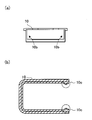
- the case portion 10 is formed by an upper surface 10a, a lower surface, and side surfaces of the case portion 10 in order to facilitate the insertion and removal of the probe 50 (in other words, in order to make the case portion 10 easy to attach to and detach from the probe 50).
- Rail 10b (see FIG. 2A). 2A is a plan view of the case portion 10 viewed from the y-axis direction in FIG.
- a hook 10c is formed inside the case portion 10 to prevent the probe 50 inserted into the case portion 10 from dropping off (see FIG. 2B).
- 2B is a cross-sectional view of the case portion 10 cut along the xy plane in FIG.
- the upper surface 10a of the case portion 10 is so flush with the light emitting / receiving surface 51a of the probe 50 when the case portion 10 is attached to the probe 50 (see FIG. 4) (so-called “level”). To be formed.
- the medical tape 20 of the fixing member 1 is composed of a single-sided tape 21 and a double-sided tape 22 as shown in FIG. As shown in FIG. 3, the case portion 10 is sandwiched between a single-sided tape 21 and a double-sided tape 22. Here, there is a portion that is not covered with the double-sided tape 22 on the upper surface 10a of the case portion 10 so that the light emitting / receiving surface 51a is exposed when the case portion 10 is attached to the probe 50.
- the fixing member 1 is configured to be detachable from the probe 50 of the laser blood flow meter device. For this reason, after the use of the laser blood flow meter device, only the fixing member 1 needs to be replaced, and the probe 50 can be used repeatedly. That is, in the blood flow measurement by the laser blood flow meter device, only the fixing member 1 may be disposable. Therefore, the running cost of the laser blood flow meter device can be reduced by using the fixing member 1.
- the case portion 10 includes the rail 10b, the user of the fixing member 1 can relatively easily attach and detach the case portion 10 to the probe 50 and detach the case portion 10 from the probe 50. .
- the case portion 10 has a specific shape, the position of the probe 50 in the case portion 10 can be fixed as compared with, for example, a bag-like member.
- the upper surface 10a of the case portion 10 and the light emitting / receiving surface 51a of the probe 50 have the same height, so the surface of the living body and the light emitting / receiving surface 51a at the time of measurement. Variation in the distance between the two can be suppressed. As a result, the reliability of the measurement result of the laser blood flow meter device can be improved.
- the area of the upper surface 10 a of the case portion 10 is larger than the area of the light emitting / receiving surface 51 a of the probe 50.
- the upper surface 10a of the case portion 10 and the light emitting / receiving surface 51a of the probe 50 have the same height. For this reason, when the probe 50 of the laser blood flow meter device is attached to the living body using the fixing member 1, the contact area becomes relatively large, so that the pressure applied to the living body can be reduced.
- the “upper surface 10a” and the “rail 10b” according to the embodiment are examples of the “one surface” and the “first fitting portion” according to the present invention, respectively.
- FIG. 5 is a diagram illustrating a fitting portion of each of the case portion of the fixing member and the probe of the laser blood flow meter device according to the modification.
- a groove 10d that fits with a ridge 52a formed on the side surface of the support 52 of the probe 50 is formed inside the case 10 of the fixing member 1 according to the modification. Has been.
- the ridge portion 10 e that fits into the groove portion 52 b formed on the side surface of the support portion 52 of the probe 50. Is formed.
- the “groove portion 10d” and the “ridge portion 10e” according to the modification are other examples of the “first fitting portion” according to the present invention.
- the “projection strip 52a” and the “groove 52b” according to the modification are examples of the “second fitting portion” according to the present invention.
- the fixing member 1 may include, for example, a head band, a torso band, an ankle band, or the like instead of the medical tape 20.
- SYMBOLS 1 Fixed member, 10 ... Case part, 10a ... Upper surface, 10b ... Rail, 10c ... Hook, 10d, 52b ... Groove part, 10e, 52a ... Projection part, 20 ... Medical tape, 50 ... Probe, 51 ... Detection part, 51a ... Light emitting / receiving surface, 52 ... Supporting part
Landscapes
- Health & Medical Sciences (AREA)
- Life Sciences & Earth Sciences (AREA)
- Cardiology (AREA)
- Engineering & Computer Science (AREA)
- Heart & Thoracic Surgery (AREA)
- Surgery (AREA)
- Biophysics (AREA)
- Pathology (AREA)
- Physiology (AREA)
- Biomedical Technology (AREA)
- Veterinary Medicine (AREA)
- Medical Informatics (AREA)
- Molecular Biology (AREA)
- Physics & Mathematics (AREA)
- Animal Behavior & Ethology (AREA)
- General Health & Medical Sciences (AREA)
- Public Health (AREA)
- Hematology (AREA)
- Signal Processing (AREA)
- Measuring Pulse, Heart Rate, Blood Pressure Or Blood Flow (AREA)
- Measurement Of The Respiration, Hearing Ability, Form, And Blood Characteristics Of Living Organisms (AREA)
Abstract
固定部材(1)は、生体に係る情報である生体情報を検出するプローブ(50)を、生体の所定部位に接触配置又は近接配置する固定部材である。当該固定部材は、プローブの一部を露出させつつ、プローブをその周囲から着脱可能に覆うケース部(10)を備える。ケース部は、プローブと嵌合する第1嵌合部(10b、10d、10e)を有する。
Description
本発明は、生体に生体情報取得装置を固定するための固定部材、及び生体情報取得装置の技術分野に関する。
この種の生体情報取得装置は、その測定時に、該生体情報取得装置のプローブが、例えば両面テープ等の固定部材により生体に取り付けられることがある。この場合、プローブ及び固定部材が使い捨て部材として扱われることが多く、生体情報取得装置のランニングコストが比較的高くなる。
或いは、生体情報取得装置のプローブが、生体の指等を挟み込むことが可能なクリップ部に設けられている、所謂クリップタイプの生体情報取得装置が提案されている。しかしながら、その測定時に、クリップ部により生体の指等が圧迫されるので、長時間の測定には向かない。
この種の固定部材として、例えば、生体情報取得装置の一例としてのオキシメータのプローブが収納される袋状本体部と、該袋状本体部の測定指への装着時に、指の根元側に位置し測定指が遊嵌される第1のリング状係止部と、指先側に位置し袋状本体部を測定指の指先部分に密着固定させる第2のリング状係止部と、を備えるプローブカバーが提案されている(特許文献1参照)。
特許文献1に記載のオキシメータは、所謂クリップタイプのものであるが、プローブカバーを用いることにより、測定時の生体の圧迫を軽減している。特許文献1に記載の技術では、プローブカバーを用いることにより、プローブの再利用を可能とし、ランニングコストを低減している。
特許文献1に記載の技術には、プローブカバーのプローブへの取り付けに関して改善の余地がある。
本発明は、上記事柄に鑑みてなされたものであり、生体情報取得装置のプローブの着脱を容易とする固定部材及び生体情報取得装置を提供することを課題とする。
本発明の固定部材は、上記課題を解決するために、生体に係る情報である生体情報を検出するプローブを、前記生体の所定部位に接触配置又は近接配置する固定部材であって、前記プローブの一部を露出させつつ、前記プローブをその周囲から着脱可能に覆うケース部を備え、前記ケース部は、前記プローブと嵌合する第1嵌合部を有する。
本発明の生体情報取得装置は、上記課題を解決するために、プローブを備え、前記プローブは、生体に係る情報である生体情報を検出する検出部と、前記検出部を支持する支持部とを有し、前記支持部は、前記プローブを前記生体の所定部位に接触配置又は近接配置する固定部材と嵌合する第2嵌合部を有する。
本発明の作用及び他の利得は次に説明する実施するための形態から明らかにされる。
本発明の固定部材及び生体情報取得装置各々に係る実施形態を説明する。
(固定部材)
実施形態に係る固定部材は、生体に係る情報である生体情報を検出するプローブを、生体の所定部位に接触配置又は近接配置する固定部材である。生体情報は、例えば血流量、血中酸素飽和度、脈拍、体温等であるが、本実施形態では特に限定されない。
実施形態に係る固定部材は、生体に係る情報である生体情報を検出するプローブを、生体の所定部位に接触配置又は近接配置する固定部材である。生体情報は、例えば血流量、血中酸素飽和度、脈拍、体温等であるが、本実施形態では特に限定されない。
固定部材は、プローブの一部を露出させつつ、該プローブをその周囲から着脱可能に覆うケース部を備える。本実施形態では特に、ケース部は、プローブと嵌合する第1嵌合部を有する。
本実施形態に係る固定部材によれば、ケース部が第1嵌合部を有しているので、比較的容易にして、固定部材をプローブに装着し、固定部材をプローブから脱離することができる。特に、第1嵌合部によりケース部内におけるプローブの位置を固定することができる。加えて、固定部材のみを使い捨てとすればよいので、生体情報取得装置のランニングコストを低減することができる。
実施形態に係る固定部材の一態様では、当該固定部材は、ケース部を、生体に固定するための医療用テープを更に備える。
この態様によれば、ケース部に医療用テープが取り付けられた状態で、当該固定部材が提供される。このため、ユーザが、例えばテープ、バンド等の用具を別途用意する必要がなく実用上非常に有利である。
特に、当該固定部材の使用時には、ケース部が医療用テープにより生体に固定されるので、所謂クリップタイプに比べ、生体の圧迫を抑制しつつ、当該固定部材が生体から外れることを好適に防止することができる。
実施形態に係る固定部材の他の態様では、第1嵌合部には、プローブの脱落を防止するフックが形成されている。
この態様によれば、測定中に当該固定部材からプローブが脱落することを防止することができ、実用上非常に有利である。
実施形態に係る固定部材の他の態様では、プローブは、生体に光を照射する発光素子及び生体からの戻り光を受光する受光素子が配置された受発光面を有しており、ケース部の一の面は、受発光面と同一面高さになるように形成されている。尚、「同一面高さ」は、完全に同一の高さである場合に限らず、実践上同一とみなせる高さを含む概念である。
ここで、プローブがケース部に装着された場合に、受発光面がケース部の一の面に対して凹んでいると、当該固定部材が生体に取り付けられる際の押しつけ方により生体表面の変形のしかたが異なり、生体表面と受発光面との間の距離を一定に保つことが難しい。特に、生体情報としての血流量が測定される場合、生体表面と受発光面との間の距離によって血流信号の大きさが変化してしまい、測定結果の信頼性が低下する可能性がある。
或いは、プローブがケース部に装着された場合に、受発光面がケース部の一の面から突出していると、当該固定部材が生体に取り付けられた際に、受発光面が生体を比較的強く圧迫してしまう。特に、生体情報としての血流量が測定される場合、生体が比較的強く圧迫されると血流信号が小さくなる傾向があり、測定結果の信頼性が低下する可能性がある。
この態様のように、ケース部の一の面が、プローブの受発光面と同一面高さになるように形成されていれば、プローブがケース部に装着された場合に、ケース部の一の面とプローブの受発光面との間に段差は生じない。従って、この態様によれば、生体表面と受発光面との間の距離のばらつきを抑制し、該ばらつきに起因する測定結果への影響を抑制することができる。
(生体情報取得装置)
実施形態に係る生体情報取得装置は、生体に係る情報である生体情報を検出する検出部と、該検出部を支持する支持部とを有するプローブを備えて構成されている。本実施形態では特に、支持部は、プローブを生体の所定部位に接触配置又は近接配置する固定部材と嵌合する第2嵌合部を有する。
実施形態に係る生体情報取得装置は、生体に係る情報である生体情報を検出する検出部と、該検出部を支持する支持部とを有するプローブを備えて構成されている。本実施形態では特に、支持部は、プローブを生体の所定部位に接触配置又は近接配置する固定部材と嵌合する第2嵌合部を有する。
本実施形態に係る生体情報取得装置によれば、プローブの支持部が第2嵌合部を有しているので、比較的容易にして、固定部材をプローブに装着し、固定部材をプローブから脱離することができる。加えて、固定部材のみを使い捨てとすればよいので、生体情報取得装置のランニングコストを低減することができる。
本発明の固定部材に係る実施例について図面を参照して説明する。以下の実施例では、生体情報取得装置の一例としてレーザ血流計装置を挙げる。尚、以下で参照する各図においては、各部材を図面上で認識可能な程度の大きさとするため、各部材の縮尺を適宜異ならしめてある。
(固定部材の構成)
実施例に係る固定部材の概要について、図1を参照して説明する。図1は、実施例に係る固定部材を示す斜視図である。
実施例に係る固定部材の概要について、図1を参照して説明する。図1は、実施例に係る固定部材を示す斜視図である。
図1において、固定部材1は、レーザ血流計装置のプローブ50に装着されるケース部10と、該ケース部10を生体に固定するための医療用テープ20と、を備えて構成されている。当然のことながら、ケース部10は、プローブ50の寸法に適した寸法に構成されている。
ここで、プローブ50は、生体情報としての血流量を検出する検出部51と、該検出部51を支持する支持部52とを備えて構成されている。検出部51の受発光面51aには、測定対象である生体に対して光を照射する、発光素子の一例としての、半導体レーザと、該生体からの散乱光を受光する受光素子とが配置されている。
プローブ50は、図1におけるy軸方向にスライドされることにより、ケース部10に挿入される、又は、ケース部10から抜き取られる。ケース部10には、プローブ50の抜き差しを容易とするために(言い換えれば、プローブ50へのケース部10の着脱を容易とするために)、ケース部10の上面10a、下面及び側面により形成されたレール10bを有する(図2(a)参照)。尚、図2(a)は、図1におけるy軸方向から見たケース部10の平面図である。
ケース部10の内部には、該ケース部10に挿入されたプローブ50の脱落を防止するために、フック10cが形成されている(図2(b)参照)。尚、図2(b)は、図1におけるxy平面でケース部10を切った断面図である。
図1に示すように、プローブ50がケース部10に挿入されたとき(つまり、ケース部10がプローブ50に装着されたとき)に、プローブ50の受発光面51aが露出するように(図4参照)、ケース部10の上面10aにはスリットが形成されている。
ケース部10の上面10aは、プローブ50にケース部10が装着されたとき(図4参照)、プローブ50の受発光面51aと同一面高さになるように(所謂“面一”となるように)形成されている。
固定部材1の医療テープ20は、図3に示すように、片面テープ21及び両面テープ22から構成されている。図3に示すようにケース部10は、片面テープ21と両面テープ22との間に挟み込まれている。ここで、ケース部10がプローブ50に装着されたときに受発光面51aが露出されるように、ケース部10の上面10aには両面テープ22により覆われない部分が存在する。
(技術的効果)
固定部材1は、レーザ血流計装置のプローブ50に着脱可能に構成されている。このため、レーザ血流計装置の使用後は、固定部材1のみを交換すればよく、プローブ50は繰り返し使用することができる。つまり、レーザ血流計装置による血流量測定では、固定部材1のみを使い捨てとすればよい。従って、固定部材1を用いることにより、レーザ血流計装置のランニングコストを低減することができる。
固定部材1は、レーザ血流計装置のプローブ50に着脱可能に構成されている。このため、レーザ血流計装置の使用後は、固定部材1のみを交換すればよく、プローブ50は繰り返し使用することができる。つまり、レーザ血流計装置による血流量測定では、固定部材1のみを使い捨てとすればよい。従って、固定部材1を用いることにより、レーザ血流計装置のランニングコストを低減することができる。
ケース部10がレール10bを有するが故に、当該固定部材1のユーザは、比較的容易にして、ケース部10をプローブ50に装着し、また、ケース部10をプローブ50から脱離することができる。特に、ケース部10は特定の形状を有しているので、例えば袋状部材に比べて、ケース部10内におけるプローブ50の位置を固定することができる。
上述の如く、プローブ50にケース部10が装着されたとき、ケース部10の上面10aとプローブ50の受発光面51aとが同一面高さになるので、測定時における生体表面と受発光面51aとの間の距離のばらつきを抑制することができる。この結果、レーザ血流計装置の測定結果の信頼性を向上させることができる。
図4に示すように、ケース部10の上面10aの面積は、プローブ50の受発光面51aの面積に比べて大きい。そして、プローブ50にケース部10が装着されたとき、ケース部10の上面10aとプローブ50の受発光面51aとが同一面高さになる。このため、固定部材1を用いてレーザ血流計装置のプローブ50が生体に取り付けられるとき、接触面積が比較的大きくなるので、生体に加わる圧力を低減することができる。
実施例に係る「上面10a」及び「レール10b」は、夫々、本発明に係る「一の面」及び「第1嵌合部」の一例である。
<変形例>
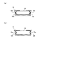
固定部材1の変形例について、図5を参照して説明する。図5は、変形例に係る固定部材のケース部、及びレーザ血流計装置のプローブ各々の嵌合部を示す図である。
固定部材1の変形例について、図5を参照して説明する。図5は、変形例に係る固定部材のケース部、及びレーザ血流計装置のプローブ各々の嵌合部を示す図である。
変形例に係る固定部材1のケース部10の内部には、図5(a)に示すように、プローブ50の支持部52の側面に形成された凸条部52aと嵌合する溝部10dが形成されている。
或いは、変形例に係る固定部材1のケース部10の内部には、図5(b)に示すように、プローブ50の支持部52の側面に形成された溝部52bと嵌合する凸条部10eが形成されている。
変形例に係る「溝部10d」及び「凸条部10e」は、本発明に係る「第1嵌合部」の他の例である。変形例に係る「凸条部52a」及び「溝部52b」は、本発明に係る「第2嵌合部」の一例である。
尚、固定部材1は、医療テープ20に代えて、例えばヘッドバンド、胴バンド、足首バンド等を備えていてもよい。
本発明は、上述した実施形態に限られるものではなく、請求の範囲及び明細書全体から読み取れる発明の要旨或いは思想に反しない範囲で適宜変更可能であり、そのような変更を伴う固定部材及び生体情報取得装置もまた本発明の技術的範囲に含まれるものである。
1…固定部材、10…ケース部、10a…上面、10b…レール、10c…フック、10d、52b…溝部、10e、52a…凸条部、20…医療テープ、50…プローブ、51…検出部、51a…受発光面、52…支持部
Claims (5)
- 生体に係る情報である生体情報を検出するプローブを、前記生体の所定部位に接触配置又は近接配置する固定部材であって、
前記プローブの一部を露出させつつ、前記プローブをその周囲から着脱可能に覆うケース部を備え、
前記ケース部は、前記プローブと嵌合する第1嵌合部を有する
ことを特徴とする固定部材。 - 前記ケース部を、前記生体に固定するための医療用テープを更に備えることを特徴とする請求項1に記載の固定部材。
- 前記第1嵌合部には、前記プローブの脱落を防止するフックが形成されていることを特徴とする請求項1に記載の固定部材。
- 前記プローブは、前記生体に光を照射する発光素子及び前記生体からの戻り光を受光する受光素子が配置された受発光面を有しており、
前記ケース部の一の面は、前記受発光面と同一面高さになるように形成されている
ことを特徴とする請求項1に記載の固定部材。 - プローブを備え、
前記プローブは、生体に係る情報である生体情報を検出する検出部と、前記検出部を支持する支持部とを有し、
前記支持部は、前記プローブを前記生体の所定部位に接触配置又は近接配置する固定部材と嵌合する第2嵌合部を有する
ことを特徴とする生体情報取得装置。
Priority Applications (2)
| Application Number | Priority Date | Filing Date | Title |
|---|---|---|---|
| PCT/JP2016/055225 WO2017145262A1 (ja) | 2016-02-23 | 2016-02-23 | 固定部材及び生体情報取得装置 |
| JP2018501448A JPWO2017145262A1 (ja) | 2016-02-23 | 2016-02-23 | 固定部材及び生体情報取得装置 |
Applications Claiming Priority (1)
| Application Number | Priority Date | Filing Date | Title |
|---|---|---|---|
| PCT/JP2016/055225 WO2017145262A1 (ja) | 2016-02-23 | 2016-02-23 | 固定部材及び生体情報取得装置 |
Publications (1)
| Publication Number | Publication Date |
|---|---|
| WO2017145262A1 true WO2017145262A1 (ja) | 2017-08-31 |
Family
ID=59684844
Family Applications (1)
| Application Number | Title | Priority Date | Filing Date |
|---|---|---|---|
| PCT/JP2016/055225 Ceased WO2017145262A1 (ja) | 2016-02-23 | 2016-02-23 | 固定部材及び生体情報取得装置 |
Country Status (2)
| Country | Link |
|---|---|
| JP (1) | JPWO2017145262A1 (ja) |
| WO (1) | WO2017145262A1 (ja) |
Citations (2)
| Publication number | Priority date | Publication date | Assignee | Title |
|---|---|---|---|---|
| JP2003225215A (ja) * | 2001-11-28 | 2003-08-12 | Nippon Koden Corp | パルスフォトメトリープローブ |
| JP2004065911A (ja) * | 2002-06-10 | 2004-03-04 | Nippon Seimitsu Sokki Kk | 脈拍計と、その脈拍計の装着方法 |
Family Cites Families (3)
| Publication number | Priority date | Publication date | Assignee | Title |
|---|---|---|---|---|
| JPH0530760U (ja) * | 1991-09-30 | 1993-04-23 | 株式会社島津製作所 | 光計測装置のプローブホルダー |
| JPH11128173A (ja) * | 1997-10-27 | 1999-05-18 | Omron Corp | 生体装着用プローブ |
| WO2005053543A1 (ja) * | 2003-12-02 | 2005-06-16 | Hitachi Medical Corporation | 生体光計測装置用プローブ装置 |
-
2016
- 2016-02-23 WO PCT/JP2016/055225 patent/WO2017145262A1/ja not_active Ceased
- 2016-02-23 JP JP2018501448A patent/JPWO2017145262A1/ja active Pending
Patent Citations (2)
| Publication number | Priority date | Publication date | Assignee | Title |
|---|---|---|---|---|
| JP2003225215A (ja) * | 2001-11-28 | 2003-08-12 | Nippon Koden Corp | パルスフォトメトリープローブ |
| JP2004065911A (ja) * | 2002-06-10 | 2004-03-04 | Nippon Seimitsu Sokki Kk | 脈拍計と、その脈拍計の装着方法 |
Also Published As
| Publication number | Publication date |
|---|---|
| JPWO2017145262A1 (ja) | 2018-12-13 |
Similar Documents
| Publication | Publication Date | Title |
|---|---|---|
| US20230404445A1 (en) | Non-invasive physiological sensor cover | |
| KR102631707B1 (ko) | 생체정보 측정 장치 및 방법 | |
| JP5565463B2 (ja) | 脈波センサ装置 | |
| EP3790458B1 (en) | A displacement sensor for use in measuring biological parameters | |
| JP6431697B2 (ja) | 手首装着型パルスオキシメータ | |
| US20070038050A1 (en) | Device for use with reflective pulse oximetry | |
| JP4914916B2 (ja) | 生体情報計測装置 | |
| JP2015039421A (ja) | 脈波測定装置 | |
| WO2020116527A1 (ja) | 生体情報測定器 | |
| JPWO2017145262A1 (ja) | 固定部材及び生体情報取得装置 | |
| KR102200165B1 (ko) | 포도당 테스트 배열체 및 방법 | |
| JP2011200267A (ja) | センサー装置及び生体情報測定装置 | |
| JP6781319B2 (ja) | 情報取得装置 | |
| TWI766894B (zh) | 測定體液中分析物濃度之方法及測量分析物濃度的裝置 | |
| JP2015217008A (ja) | 測定台及び分析装置 | |
| JP2018134469A (ja) | 情報取得装置 | |
| TWM584663U (zh) | 生物感測器 | |
| JP2021006284A (ja) | 情報取得装置 | |
| JP2010131243A (ja) | 生態情報計測装置 | |
| JP2016013232A (ja) | 生体センサ | |
| HK40042726A (en) | A displacement sensor for use in measuring biological parameters | |
| HK40042726B (en) | A displacement sensor for use in measuring biological parameters |
Legal Events
| Date | Code | Title | Description |
|---|---|---|---|
| WWE | Wipo information: entry into national phase |
Ref document number: 2018501448 Country of ref document: JP |
|
| NENP | Non-entry into the national phase |
Ref country code: DE |
|
| 121 | Ep: the epo has been informed by wipo that ep was designated in this application |
Ref document number: 16891421 Country of ref document: EP Kind code of ref document: A1 |
|
| 122 | Ep: pct application non-entry in european phase |
Ref document number: 16891421 Country of ref document: EP Kind code of ref document: A1 |