WO2017141785A1 - 設計書の入出力装置、設計書の入出力システム及び設計書の入出力方法 - Google Patents
設計書の入出力装置、設計書の入出力システム及び設計書の入出力方法 Download PDFInfo
- Publication number
- WO2017141785A1 WO2017141785A1 PCT/JP2017/004537 JP2017004537W WO2017141785A1 WO 2017141785 A1 WO2017141785 A1 WO 2017141785A1 JP 2017004537 W JP2017004537 W JP 2017004537W WO 2017141785 A1 WO2017141785 A1 WO 2017141785A1
- Authority
- WO
- WIPO (PCT)
- Prior art keywords
- design
- design information
- input
- design document
- information
- Prior art date
Links
Images


Classifications
-
- G—PHYSICS
- G06—COMPUTING; CALCULATING OR COUNTING
- G06F—ELECTRIC DIGITAL DATA PROCESSING
- G06F9/00—Arrangements for program control, e.g. control units
- G06F9/06—Arrangements for program control, e.g. control units using stored programs, i.e. using an internal store of processing equipment to receive or retain programs
- G06F9/44—Arrangements for executing specific programs
-
- G—PHYSICS
- G06—COMPUTING; CALCULATING OR COUNTING
- G06F—ELECTRIC DIGITAL DATA PROCESSING
- G06F16/00—Information retrieval; Database structures therefor; File system structures therefor
-
- G—PHYSICS
- G06—COMPUTING; CALCULATING OR COUNTING
- G06Q—INFORMATION AND COMMUNICATION TECHNOLOGY [ICT] SPECIALLY ADAPTED FOR ADMINISTRATIVE, COMMERCIAL, FINANCIAL, MANAGERIAL OR SUPERVISORY PURPOSES; SYSTEMS OR METHODS SPECIALLY ADAPTED FOR ADMINISTRATIVE, COMMERCIAL, FINANCIAL, MANAGERIAL OR SUPERVISORY PURPOSES, NOT OTHERWISE PROVIDED FOR
- G06Q10/00—Administration; Management
- G06Q10/10—Office automation; Time management
Definitions
- the present invention relates to a technology for creating and inputting / outputting design documents having various layouts created and maintained by, for example, system development, etc., using spreadsheet software for the purpose of centralized management by the storage device.
- design documents are created to describe design information related to the screens and databases that make up the computer system.
- the design document is created by word processing software, spreadsheet (spreadsheet) software, or the like.
- spreadsheet readsheet
- a design document in the form of a spreadsheet is targeted.
- Design documents are media for sharing design information among system developers.
- the design document is structurally analyzed, and then the design information is converted into a database format for centralized management.
- Patent Document 1 is known as an apparatus for mechanizing input / output between data written in such a spreadsheet and data in a database.
- Design documents handled in system development differ in type, description items, and layout for each development project, and layout and items may be changed during development and maintenance.
- the prior art requires a database schema change and data migration accompanying the schema change.
- screens and processes for searching and editing design information stored in the database in accordance with a schema may be created. In this case, there has been a problem that the screens and processes need to be modified along with the schema change.
- the present invention has been made in view of the above problems, and an object of the present invention is to make it unnecessary to modify a database schema when items or layouts described in a design document are changed.
- the present invention is a design document input / output device that includes a processor and a memory and processes a spreadsheet format design document.
- the design information definition is generated in advance and defines the structure of the design document.
- a storage unit for storing a design information template having a definition for converting the design document in a spreadsheet format into a semi-structured data format; and receiving the design document in the spreadsheet format;
- a conversion unit that sets the design information template based on the design information definition and outputs the design information in the semi-structure data format.
- Design information in XML format can be stored as an XML file, stored in one column of the database, or stored in a storage device in a format such as an XML database, so even if the layout of the design document is changed There is no need to change the database schema.
- XML format a semi-structured data format
- FIG. 1 is a block diagram illustrating an example of a hardware configuration of a computer system according to a first embodiment of this invention.
- 1 is a block diagram illustrating an example of functional elements of a computer system according to a first embodiment of this invention. It is a figure which shows Example 1 of this invention and shows an example of design document meta information. It is a figure which shows Example 1 of this invention and shows an example of design document meta information. It is a figure which shows Example 1 of this invention and shows an example of a design information definition body. It is a figure which shows Example 1 of this invention and shows an example of a design information model. It is a figure which shows Example 1 of this invention and shows an example of design information. It is a figure which shows Example 1 of this invention and shows an example of a design document model.
- Example 1 of this invention shows an example of a design document. It is a figure which shows Example 1 of this invention and shows an example of a design document. It is a screen image which shows Example 1 of this invention and shows an example of a design document registration screen. It is a screen image which shows Example 1 of this invention and shows an example of a search condition input screen. It is a figure which shows Example 1 of this invention and shows an example of a search condition input screen. It is a screen image which shows Example 1 of this invention and shows an example of a design information search result display screen. It is a screen image which shows Example 1 of this invention and shows an example of a design information search result display screen.
- Example 1 of this invention It is a screen image which shows Example 1 of this invention and shows an example of a design information search result display screen. It is a screen image which shows Example 1 of this invention and shows an example of a design information reference and edit screen. It is Example 1 of this invention, and is a flowchart which shows an example of a process of a design document meta information conversion part. It is a flowchart which shows Example 1 of this invention and shows an example of a process of a design information reading and conversion part. It is Example 1 of this invention, and is a flowchart which shows an example of a process of the design information search condition input screen output part. It is a flowchart which shows Example 1 of this invention and shows an example of a process of a design information search and a result display screen output part.
- Example 1 of this invention is a flowchart which shows an example of a process of a design information reference and edit screen output part. It is Example 1 of this invention, and is a flowchart which shows an example of a process of the design information edit process part.
- 1 is a block diagram illustrating an example of a configuration of a computer according to a first embodiment of this invention. It is Example 2 of this invention and is a block diagram which shows an example of the functional element of a computer.
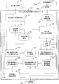
- the computer system according to the first embodiment of the present invention is a spreadsheet design document input / output system 100 including a design document meta information conversion device 101, a design information input / output device 102, and a client device 103.
- FIG. 1 is a block diagram showing an example of a hardware configuration of a computer system.
- the design document meta information conversion apparatus 101, the design information input / output apparatus 102, and the client apparatus 103 include a control and calculation unit 101 a, 102 a, and 103 a, an input unit 101 b, 102 b, and 103 b, and a storage unit.
- the computer system includes 101c, 102c, and 103c, output units 101d, 102d, and 103d, and communication interface units 104a, 104b, and 104c. Note that the communication interface units 104a, 104b, and 104c are connected via a network.
- the design document meta information conversion apparatus 101 and the design information input / output apparatus 102 realize data communication cooperation between the apparatuses via the communication interface units 104a and 104b.
- the design information input / output device 102 and the client device 103 realize data communication between the devices via the communication interface units 104b and 104c.
- These design document meta information conversion apparatus 101, design information input / output apparatus 102, and client apparatus 103 may be integrated.
- the storage units 101c, 102c, and 103c are configured by a storage device including a nonvolatile storage medium such as a hard disk drive.
- a computer software program that functions as the design document meta information conversion unit 201 and the table calculation unit 210 is stored in the storage unit 101 c of the design document meta information conversion apparatus 101.
- the storage unit 102c of the design information input / output device 102 includes a design document reading / conversion unit 202, a design information search condition input screen output unit 203, a design information search / result display screen output unit 204, a design information reference / edit screen output unit 205. And a computer software program that functions as the design information editing processing unit 206 is stored.
- the storage unit 103c of the client apparatus 103 stores a computer program that functions as a spreadsheet unit 211 that edits a design document, a computer program that functions as a browser 212, a spreadsheet design document, and a design document model. .
- the storage unit 103c also stores a computer software program that functions as a browser that displays the screen transmitted from the design information input / output device 102 on the output unit 103d.
- the control and calculation units 101a, 102a, and 103a include a processor and a memory as will be described later, and a program is loaded into the memory from the storage units 101c, 102c, and 103c and executed by the processor.
- the design document meta information conversion unit 201 and the table calculation unit 210 realize each function by being read from the storage unit 101c and executed by the control and calculation unit 101a.
- the design document reading / conversion unit 202, the design information search condition input screen output unit 203, the design information search / result display screen output unit 204, and the design information reference / edit screen output unit 205 are read from the storage unit 102c by the control / calculation unit 102a.
- Each function is realized by being issued and executed.
- the spreadsheet unit 211 and the browser 212 realize each function by being read from the storage unit 103c and executed by the control and calculation unit 103a.
- the input units 101b, 102b, and 103b are input devices such as a mouse.
- the output units 101d, 102d, and 103d are display devices such as various displays, and other output devices such as various printers can be connected thereto.
- FIG. 20 is a block diagram showing an example of a computer constituting the spreadsheet-format design input / output system 100.
- the illustrated example shows an example of the computer 10 operating as the design document meta information conversion apparatus 101, but the design information input / output apparatus 102 and the client apparatus 103 have the same configuration.
- the computer 10 is connected to a processor 60 that performs control and arithmetic processing, a memory 70 that stores programs and data, a communication interface unit 104a that is connected to the network 40 and communicates with other computers, and a storage unit 101c.
- the control and calculation units 101 a, 102 a, and 103 a illustrated in FIG. 1 correspond to the processor 60 and the memory 70.
- the processor 60 is composed of a heterogeneous multi-core processor, and includes a plurality of CPU cores 61 and a plurality of GPU cores 62.
- the processor 60 also includes a memory controller 63 connected to the memory 70, a display controller 65 connected to the output unit 101d, an I / O processor 83, a communication interface unit 104a, and an I / O connected to the storage interface 86.
- the input unit 101b includes a keyboard, a mouse, and a touch panel.
- the output unit 101d includes a display.
- the memory 70 is loaded with the OS 71 and executed by the processor 60.
- the OS 71 executes one or more software 72 such as a design document meta information conversion unit and a spreadsheet unit.
- Each functional unit such as the design document meta information conversion unit 201 is loaded into the memory 70 as a program.
- the processor 60 operates as a functional unit that provides a predetermined function by processing according to a program of each functional unit.
- the processor 60 functions as the design document meta information conversion unit 201 by performing processing according to the design document meta information conversion program. The same applies to other programs.
- the processor 60 also operates as a functional unit that provides each function of a plurality of processes executed by each program.
- a computer and a computer system are an apparatus and a system including these functional units.
- Information such as programs and tables for realizing each function of the design document meta information conversion apparatus 101 is stored in a storage device 101c, a nonvolatile semiconductor memory, a hard disk drive, a storage device such as an SSD (Solid State Drive), or an IC card, SD. It can be stored in a computer-readable non-transitory data storage medium such as a card or DVD.
- FIG. 2 shows an example of a functional block diagram of the computer system.
- the design information input / output device 102 is a computer that processes a design document used in a user's business.
- the design document meta information conversion apparatus 101 generates, in a spreadsheet format, design document meta information 301 (FIG. 3) that defines the structure (items and layout) of the design document 304 b (FIG. 7B) according to a developer's operation. .
- the design document meta information conversion unit 201 reads the design document meta information 301 and defines a design information definition body 302 (FIG. 4) that defines the structure of the design document 304 b and the design document 304 b.
- the data is converted into a design information template 303 (FIG. 5) used for conversion.
- the design document meta information conversion device 101 stores the converted design information definition body 302 and the design information template 303 in the storage unit 102c of the design information input / output device 102 used by the user.
- a developer who uses the design document meta information conversion apparatus 101 generates a design document template 304a (FIG. 7A) corresponding to the design document meta information 301, and a storage unit of the design information input / output apparatus 102 used by the user. It is stored in 102c.
- the user of the client apparatus 103 reads the design document template 304a by the spreadsheet unit 210, generates a spreadsheet-format design document 304b, and stores it in the storage unit 102c.
- the client device 103 requests registration of the design document 304b in accordance with a user operation.
- the design document meta information conversion unit 201 outputs a design document registration screen 305 to the client device 103.
- the client apparatus 103 executes registration of the design document 304b from the design document registration screen 305.
- the design information input / output device 102 accepts the spreadsheet format design document 304b
- the design document reading and conversion unit 202 reads the design information definition body 302 and the design information template 303, and as described later, the design format input / output device 102
- the design document 304b is converted into design information 310 in XML format and stored in the storage unit 102c.
- the design information search condition input screen output unit 203 reads the design information definition body 302, generates a search condition input screen 306, and outputs it to the client device 103.
- the search condition input screen 306 is a generic term for the search condition input screens 306a and 306b in FIGS.
- the design information search and result display screen output unit 204 executes the search, refers to the design information definition body 302, and searches for the design information search result screen 307. Is transmitted to the client apparatus 103 as a search result.
- the design information search result screen 307 is a generic name for the design information search result screens 307a, 307b, and 307c shown in FIGS. 11A to 12.
- the design information reference / edit screen output unit 205 reads the design information 310 and the design information definition body 302 and references the design information. Then, an edit screen 308 is generated and output to the client device 103.
- the client device 103 can edit the design information 310 from the design information reference and edit screen 308.
- the design information editing processing unit 206 reads the design information 310 in the XML format and responds to the design information definition body 302 and the design information template 303. Then, a spreadsheet format design document 304 c is generated and transmitted to the client apparatus 103.
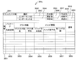
- the design document meta information 301 is an example of a file stored in the storage unit 101 c of the design document meta information conversion apparatus 101 and is used by the design document meta information conversion unit 201.
- one file is created by the spreadsheet unit 210 for each type of design document defined in the spreadsheet.
- the design document meta information 301 includes the structure of the design document 304b that defines the items used in the spreadsheet format design document 304b (design document template 304a) used by the client apparatus 103 and the layout of the cell position of each item. It is a defined file.
- One file of the design document meta information 301 includes “file type” (3011), “relation between item groups” (3012), “sheet type” (3013), and “single item group” (3014). And an element of “multiple item group” (3015).
- Element “file type” (3011) defines the type of design document for each spreadsheet format file, and includes element “local name” and element “alphabet name”.
- the element “sheet type” (3013) is defined for each sheet defined in the spreadsheet. Therefore, when a design document 304b composed of a plurality of sheets in a spreadsheet is targeted, the element “sheet type” (3013), the following “single item group” (3014), and “multiple item group” ( 3015) are defined.
- the element “sheet type” (3013) includes an element “local name” and an element “alphabet name”.
- the element “single item group” (3014) a group that defines the content of the item (single item) in which one value is defined for one item defined in the design document and additional information is defined.
- the element “single item group” (3014) includes an element “local name” and an element “alphabet name”.
- element “item number”, element “required flag”, element “single item local name”, element “single item alphabetic name”, and singular items on the spreadsheet Element “start row” and element “start column” are defined as information indicating the position, and element “type” and element “size” are defined as information necessary for displaying a single item on the screen. .
- Type defines a format for display on the browser of the client apparatus 103
- input indicates an input field
- text indicates that a character string is displayed.
- Size defines the number of input characters.
- the element “multiple item group” (3015) a group that defines the content of the item (multiple items) in which a plurality of values are defined for one item defined in the design document and additional information is defined.
- the element “multiple item group” (3015) includes an element “local name” and an element “alphabet name”. Also, as many as the number of items, element “item number”, element “required flag”, element “multi-item local name”, element “multi-item alphabetic name”, and multiple items from which position on the spreadsheet An element “start row” and an element “start column” are defined as information indicating whether to start, and an element “type” and an element “size” are defined as information required when displaying a plurality of items on the screen.
- single item group (3014) and the element “multiple item group” (3015) may be omitted or plural according to the target design document.
- the element “relation between item groups” (3012) includes an element “item number”, an element “parent item group name”, an element “child item group name”, and an element “description”. In the element “parent item group name” and the element “child item group name”, “English name” of “single item group” (3014) or “multiple item group” (3015) is entered.
- the design document meta information 301 is stored in the storage unit 101c with the above contents.
- the design document meta information 301 is created in advance by a developer who uses the design document meta information conversion apparatus 101 in correspondence with the design document 304 b used by the client apparatus 103, and is transmitted to the client apparatus 103.
- the design document meta information 301 may be created by the design document meta information conversion apparatus 101 or may be generated by another computer.
- the design document meta-information 301 is information in which configuration information including the structure and layout of the design document 304b in the spreadsheet format and the design document template 304a is defined in advance.
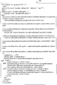
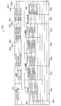
- FIG. 4 shows an example of the design information definition body 302.
- the design information definition body 302 is a file generated from one design document meta information 301 by the process of the design document meta information conversion unit 201 and stored in the storage unit 101c and the storage unit 102c.
- the data configuration will be described with reference to the design information definition body 302 of FIG.
- the design information definition body 302 is an XML format file and has “genericRule” (3021) as a root element.
- the element “genericRule” (3021) has “localName” and “name” as attributes.
- the value of “localName” is “local name” of “file type” (3011) of the design document meta information 301, and the value of “name” is “alphabetic name” of “file type” (3011) of the design document meta information 301.
- the element “genericRule” (3021) includes a plurality of elements “relationship” (3022) and element “designSpecification” (3023).
- the element “relationship” (3022) is generated by the process of the design document meta information conversion unit 201 as many as the “relationship between item groups” defined in the design document meta information 301.
- the element “relationship” (3022) has “parentItem” and “childItem” as attributes.
- the value of “parentItem” is derived from the “parent item group name” of the design document meta information 301, and the value of “childItem” is derived from the “child item group name” of the design document meta information 301. Each is set.
- the element “designSpecification” (3023) is generated by the process of the design document meta information conversion unit 201 as many as the “sheet types” defined in the design document meta information 301.
- the element “designSpecification” (3023) has “localName” and “sheetCls” as attributes.
- the value of “localName” is “local name” of “sheet type” (3013) of the design document meta information 301
- the value of “sheetCls” is “alphabetic name” of “sheet type” (3013) of the design document meta information 301.
- the element “designSpecification” (3023) includes a plurality of elements “key”.
- the element “key” is generated by the process of the design document meta information conversion unit 201 by the number of “single item groups” (3014) or “multiple item groups” (3015) of the design document meta information 301.
- the element “key” has “localName”, “name”, and “type” as attributes.
- the value of “localName” is determined by the process of the design document meta information conversion unit 201 from “local name” of “single item group” (3014) of design document meta information 301 or “local name” of “multiple item group” (3015). Is set.
- the value of “name” is determined by the process of the design document meta information conversion unit 201 from “alphabetic name” of “single item group” (3014) of design document meta information 301 or “alphabetic name” of “multiple item group” (3015). Is set.
- the value of “type” is set by the process of the design document meta information conversion unit 201 from “single” in the case of “single item group” (3014) or “list” in the case of “multiple item group” (3015).
- the element “key” includes a plurality of elements “singleItemKey” when the value set to “type” is “single”, or the element “listItemKey” when the value set to “type” is “list” Including multiple.
- the element “singleItemKey” (3024) is generated by the process of the design document meta information conversion unit 201 by the number of items defined in the “single item group” (3014) of the design document meta information 301.
- the element “singleItemKey” (3024) has “localName”, “name”, and “mandatory” as attributes.
- the value of “localName” is from “single item local name” of “single item group” (3014) of design document meta information 301, and the value of “name” is of “single item group” (3014) of design document meta information 301. From “single item alphabetic name”, the value of “mandatory” is “true” when “mandatory flag” in the design document meta information 301 is entered as “true”, and nothing is entered in “mandatory flag”. If not, “false” is set in the process of the design document meta information conversion unit 201.
- the element “singleItemKey” (3024) includes an element “spreadsheet” and an element “webScreen”.
- the element “listItemKey” (3025) is generated by the process of the design document meta information conversion unit 201 by the number of items defined in the “multiple item group” (3015) of the design document meta information 301.
- the element “listItemKey” (3025) has “localName”, “name”, and “mandatory” as attributes.
- the value of “localName” is from “multiple item local name” of “multiple item group” (3015) of design document meta information 301, and the value of “name” is “multiple item group” (3015) of design document meta information 301.
- the value of “mandatory” is “true” when “mandatory flag” in the design document meta information 301 is entered, and “true” is nothing in “mandatory flag”. In this case, “false” is set in the process of the design document meta information conversion unit 201.
- the element “listItemKey” (3025) includes one element “spreadsheet” and one element “webScreen”.
- the essential flag is a flag for identifying an item that must be used in the design document 304b. If “ ⁇ ”, the flag is an essential item in the design document 304b. An item for which the mandatory flag is set to “ ⁇ ” serves as a search key in the search process.
- the element “sheet” (3026) includes one element “cellLine” and one element “cellColumn”.
- the value of the element “cellLine” (3026) is processed from the “start line” of the design document meta information 301, and the value of the element “cellColumn” is processed from the “start column” of the design document meta information 301. To set each.
- the element “webScreen” (3027) includes one element “itemType” and one element “itemLength”.
- the value of the element “itemType” is set from the “type” of the design document meta information 301, and the value of the element “itemLength” is set from the “size” of the design document meta information 301 by the process of the design document meta information conversion unit 201. .
- the design information definition body 302 defines cell information determined by the row number (cellLine) and column number (cellColumn) of the spreadsheet-type design document 304b.
- the design document read conversion unit 202 can acquire the structure of the spreadsheet-type design document 304b by referring to the design information definition body 302 corresponding to the design document 304b.
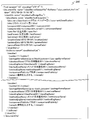
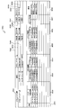
- FIG. 5 shows a design information template used for converting the spreadsheet format design document 304b into the XML format, or a design information template used for reconverting the design information 310 stored in the storage unit 102c into the XML format.
- An example of 303 is shown.
- the design information template 303 is a file generated based on the design document meta information 301 by the process of the design document meta information conversion unit 201 and stored in the storage units 101c and 102c.
- the data configuration will be described using the design information template 303 shown in FIG.
- the design information template 303 is an XML format file having “documentCls” (3031) as a root element.
- the element “documentCls” (3031) has “name”, “fileName”, and “date” as attributes.
- the value of the attribute “name” is set by the process of the design document meta information conversion unit 201 from the “alphabetic name” of the “file type” (3011) of the design document meta information 301.
- the value of the attribute “fileName” is set by the design document reading and conversion unit 202 from the “design document file name” input by the user on the design document registration screen 305.
- the value of the attribute “date” is the date when the design document 304b is registered in the storage unit 102c by the design document reading and conversion unit 202, or when the design document edit processing unit 206 generates the design document 304c. Minutes and seconds are generated in the format of “YYYY / MM / DD / HH: MM: SS”, for example.
- the element “documentCls” (3031) includes a plurality of elements “sheetCls” (3032).
- sheetCls As “sheet types” (3013) defined in the design document meta information 301 are generated by the process of the design document meta information conversion unit 201.
- “SheetCls” (3032) has “name” as an attribute. The value of the attribute “name” is set by the process of the design document meta information conversion unit 201 from “alphabetic name” of “sheet type” (3013) of the design document meta information 301.
- the element “sheetCls” (3032) includes an element “singleItems” (3033) or an element “listItems” (3037).
- Element “singleItems” (3033) is generated by the process of the design document meta information conversion unit 201 by the number of “single item groups” (3014) of the design document meta information 301.
- the element “singleItems” (3033) has “name” as an attribute.
- the value of the attribute “name” is set by the process of the design document meta information conversion unit 201 from “English name” of “single item group” (3014) of the design document meta information 301.
- a plurality of elements whose element names are “single item alphabetic names” defined in the “single item group” (3014) of the design document meta information 301 are converted into the design document meta information conversion. It is generated and included by the processing of the unit 201.
- the element value having the element name “single item alphabetic name” defined in “single item group” (3014) ⁇ of the design document meta information 301 a variable surrounded by “$ ⁇ ” is a design document meta information. Generated by the conversion unit 201.
- variable name is a format in which “alphabetic name” of “sheet type” (3013) of design document meta information 301 and “alphabetic name” of “single item group” (3014) of design document meta information 301 are connected by “.”. Thus, it is generated by the design document meta information conversion unit 201.
- the element “listItems” (3037) is generated by the process of the design document meta information conversion unit 201 by the number of “multiple item groups” (3015) of the design document meta information 301.
- the element “listItems” (3037) has “name” as an attribute.
- the value of the attribute “name” is set by the process of the design document meta information conversion unit 201 from “English name” of “multiple item group” (3015) of the design document meta information 301.
- the element “listItems” (3037) includes one element “member” (3035). Note that “#foreach ($ member in $ XXXX)” is between the element “listItems” (3037) and “member” (3035), and “#end” is immediately after the element “member” (3035).
- the design document meta-information conversion unit 201 generates a variable having a name in a format linked in the above.
- a plurality of elements whose element names are “multiple item alphabetic names” defined in “multiple item groups” (3015) of the design document meta information 301 include a design document meta information conversion unit. It is generated and included in the process 201.
- a variable enclosed by “$ ⁇ ” is a design document meta information.
- the variable name is a format in which “alphabetic name” of “sheet type” (3013) of design document meta information 301 and “alphabetic name” of “multiple item group” (3015) of design document meta information 301 are connected by “.”. Thus, it is generated by the design document meta information conversion unit 201.
- the design information template 303 defines a form for setting the value of the design document 304b in the XML format file when the design information 310 is generated. Therefore, the design document read conversion unit 202 can convert the value read from the spreadsheet format design document 304b in accordance with the design information definition body 302 into the design information template 303, thereby converting the value into the XML format design information 310. .
- FIG. 6 is a diagram illustrating an example of the design information 310.
- the design information 310 indicates a result obtained by converting the spreadsheet format design document 304 b generated by the client device 103 into the XML format by the design document reading and conversion unit 202 of the design information input / output device 102.
- the design information 310 is generated by the design document reading and conversion unit 202 as information in which the contents of the design document 304b are set in the variable $ of the design information template 303 shown in FIG.
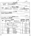
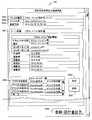
- FIG. 7A shows Example 1 of the present invention and is a diagram showing an example of a design document template 304a.
- the design document template 304 a is spreadsheet format information stored in advance in the storage unit 103 c of the client device 103.
- the design template 304a in FIG. 7A shows a state of no input.
- the design document template 304a includes a document classification 3031 indicating the type of the design document template 304a, a title 3032 for storing the title of the design document 304b, a component ID 3033, a component name 3034, a creator 3035, an updater 3036, Approver 3037, creation date 3038, update date 3039, approval date 3040, item number 3041 indicating data number, package name space 3042, class Japanese name 3043, class alphabetic name 3044, method It includes a Japanese name 3045, a method alphabetic name 3046, other component publication 3047, and a remark 3048 cell.
- FIG. 7B shows the first embodiment of the present invention and is a diagram showing an example of the design document 304b.
- the design document 304b in FIG. 7B shows the result of the user of the client apparatus 103 inputting a predetermined value in the spreadsheet unit 211 to the design document template 304a in FIG. 7A.
- the code of each cell of the design document 304b is the same as that of the design document template 304a.
- FIG. 7C shows the first embodiment of the present invention and is an example of the design document 304c.
- the design document 304c in FIG. 7C is information indicating the design information edited on the design information reference and editing screen 308 shown in FIG.
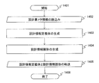
- step 1401 the design document meta information conversion unit 201 starts processing in response to an instruction from the input unit 101b.
- step 1402 the design document meta information conversion unit 201 reads a file of the design document meta information 301 registered in advance in the storage unit 101c.
- step 1403 the design document meta information conversion unit 201 generates the elements and values of the design information definition body 302 by the above-described method from the file information of the design document meta information 301 read in step 1402, and the design information definition body 302 Are generated and stored in the storage unit 101c.
- step 1404 the design document meta information conversion unit 201 generates the elements and values of the design information template 303 by the above-described method from the file information of the design document meta information 301 read in step 1402. A file is generated and stored in the storage unit 101c.
- step 1405 the design document meta information conversion unit 201 reads the file of the design information definition body 302 generated in step 1403 and the file of the design information template 303 generated in step 1404 from the storage unit 101c and reads the communication interface. Data transfer processing is performed via the unit 104 a and stored in the storage unit 102 c of the design information input / output device 102.
- step 1406 the design document meta information conversion unit 201 outputs a message indicating the completion of processing to the output unit 101d.
- the design document meta information conversion apparatus 101 generates the design information definition body 302 and the design information template 303 from the design document meta information 301 and stores them in the storage unit 102c of the design information input / output apparatus 102.
- the design document read conversion unit 202 displays the design document registration screen 305 with the design information definition body 302 as an input, and accepts a spreadsheet format design document 304b created based on the design document template 304a. Then, the design document read conversion unit 2 receives the design document 304b, the design information definition body 302 and the design document template 304a generated by the design document meta information conversion apparatus 101, and generates design information 310.
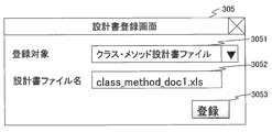
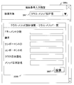
- FIG. 8 is a screen image showing an example of the design document registration screen 305 output from the design document reading conversion unit 202.
- the design document registration screen 305 includes a registration target 3051 for selecting an element “file type” of all the design document meta information 301 registered in the storage unit 102c from a pull-down list, and a “design document file name” for inputting a file name. (3052) and a “registration button” are arranged.
- the design document registration screen 305 is displayed on the output unit 103 d of the client device 103 that uses the design information input / output device 102.
- a user or an administrator who uses the client apparatus 103 selects the registration target 3051 by operating the input unit 103b and inputs the design document file name 3052 and then operates the “register button”, the design document reading and converting unit 202 is operated. As a result, design information 310 is generated.
- the design document reading and converting unit 202 that outputs the design information 310 by inputting the design document 304b in the spreadsheet format, the design information definition body 302, and the design information template 303 created based on the design document template 304a.
- An example of the process will be described with reference to the flowchart shown in FIG.
- step 1501 the design document reading and conversion unit 202 starts processing in response to an instruction from the input unit 103b of the client device 103.
- step 1502 the design request reading and conversion unit 202 of the design information input / output device 102 receives the processing request transmitted from the input unit 103b via the communication interface unit 104c, and generates the design document registration screen 305.
- the design document reading and conversion unit 202 sends a processing response to the client device 103 via the communication interface unit 104b, and displays the design document registration screen 305 on the output unit 103d of the client device 103.
- “local name” of the element “file type” of all the design document meta information 301 registered in the storage unit 102c is listed in the list of options for “registration target” (3051) on the design document registration screen 305. .
- step 1503 the client device 103 inputs “registration target” (3051) and “design document file name” (3052) on the design document registration screen 305 by operating the input unit 103b. "The button is accepted.
- the client device 103 reads a file of the design document 304b corresponding to the “design document file name” (3052) input on the design document registration screen 305 from the storage unit 103c.
- the client device 103 notifies the design information input / output device 102 of the data of the design document 304b, the “registration target” (3051) input on the design document registration screen 305, and the processing request via the communication interface unit 104c. Subsequent steps are executed by the design information input / output device 102.
- step 1504 the character string selected in the “Registration Target” (3051) of the design document registration screen 305 from the design information definition body 302 file registered in the storage unit 102c by the design document reading and conversion unit 202.
- a file of the design information definition body 302 having the same value as the attribute “localName” of the element “genericRule” (3021) of the design information definition body 302 is retrieved from the storage unit 102c and read.
- step 1505 the design document reading and converting unit 202 stores the “file type” (3011) of the design document meta information 301 read in step 1504 from the files of the design document meta information 301 registered in the storage unit 102c.
- the design information template 303 file having the same value as the “alphabetic name” as the value of the attribute “name” of the element “documentCls” (3031) of the design information template 303 is retrieved from the storage unit 102c and read.
- step 1506 the design document reading and conversion unit 202 reads the spreadsheet-type design document 304b file read in step 1503 from the design document 304b file using the design information definition body 302 read in step 1504.
- the item name (local name) and value of the item 3014 or the plurality of items 3015 are acquired.
- the value of the attribute “mandatory” of the element “singleItemKey” (3024) or the element “listItemKey” (3025) of the design information definition body 302 read in step 1504 corresponding to a single item or a plurality of items from the file of the design document 304b. If the value of the single item 3014 or the plurality of items 3015 has not been input on the file of the design document 304b despite being “true”, the design document reading and conversion unit 202 outputs an error.
- the design document reading and conversion unit 202 is an element of the design information definition body 302.
- the item name is acquired from “singleItemKey” 3014 and this attribute “name”
- the line position of the value for the item name is acquired from the element “cellLine” in the element “singleItemKey” (3024)
- the column position of the value for the item name is obtained.
- the value of the row position and the column position acquired from the element “cellColumn” in the element “singleItemKey” (3024) and acquired from the file of the design document 304b in the spreadsheet format is acquired.
- the design document reading and conversion unit 202 repeats the above processing as many times as the number of elements “singleItemKey” (3024) included in the element “key” of the design information definition body 302.
- the design document reading and conversion unit 202 reads the element “listItemKey” of the design information definition body 302. ”(3025) and the attribute name“ name ”, the line position of the value for the item name is obtained from the element“ cellLine ”in the element“ listItemKey ”(3025), and the column position of the value for the item name is the element“ From the element “cellColumn” in “listItemKey” (3025), the row position and the column position value acquired from the spreadsheet format design document 304b, and the row where the value exists by incrementing the row position one by one Get multiple values.
- the design document reading and conversion unit 202 repeats the above processing as many times as the number of elements “listItemKey” (3025) included in the element “key” of the design information definition body 302. However, the design document reading and conversion unit 202 obtains the number of values acquired from the element “listItemKey” (3025) included in the element “key” of one design information definition body 302 by the attribute “listItemKey” (3025). “mandatory” is equal to the number of values specified by “true”.
- the values up to the third line are filled, so the design document reading and conversion unit 202 has values up to the line where “item number” (3051) is “3”. To be acquired.
- step 1507 the design document reading and conversion unit 202 first sets a variable to be embedded in the design information template 303 as follows in the value acquired in step 1506.
- the design document reading and conversion unit 202 sets the value of the attribute “sheetCls” of the element “designSpecification” and the value of the attribute “name” of the element “key” of the design information definition body 302 read in step 1504 for the single item.
- a variable is set in a format in which the value of the attribute “name” of the element “singleItemKey” (3023) is concatenated with “.”, And the value of the item acquired in step 1506 is substituted for this variable.
- the design document reading and conversion unit 202 reads the value of the attribute “sheetCls” of the element “designSpecification” (3023) and the attribute “name” of the element “key” of the design information definition body 302 read in step 1504.
- This variable is a list object, and the design document reading and conversion unit 202 sets a variable whose name is the value of the attribute “name” of the element “listItemKey” (3025) of the design information definition body 302 read in step 1504. .
- the design document reading and conversion unit 202 obtains the values obtained from the list of class information (3053, 3054) and method information (3055, 3056) in the spreadsheet format design document 304b in step 1506 for each line of the list. And register this object with the list object.
- the design document reading and conversion unit 202 generates the design information 310 by replacing the variable “$” in the design information template 303 with the value of the variable set as described above. Note that the portion enclosed by “#foreach ($ member in $ XXXX)” and “#end” in the design information 310 is processed as follows.
- the design document reading and conversion unit 202 extracts “classlocalName” from “member” (3035) and sets it as the value. replace.
- the design document reading and conversion unit 202 copies the element “member” (3035) and the elements included in this element as many as the number of objects registered in the list object, and sets the variable in the element as a value. Repeat the replacement process. The design document reading and conversion unit 202 finally deletes “#foreach ($ member in $ XXXX)” and “#end”.
- step 1508 the design document reading and conversion unit 202 sets the attribute “date” of the element “documentCls” of the XML-format design information 310 generated in step 1507 to the date, date, time, and date when the above processing is executed.
- the second is set in the format of “YYYY / MM / DD / HH: MM: SS”.
- the design document reading and conversion unit 202 sets the name of the “design document file name” input by the user on the design document registration screen 305 to the value of the attribute “fileName” of the element “documentCls” illustrated in FIG. Then, the XML design information 310 file generated in step 1507 with the file name is stored in the storage unit 102c. Further, the design document reading and conversion unit 202 stores the received design document 304b in the storage unit 102c.
- the design document reading and conversion unit 202 can store the XML format design information 310 in one field of the database stored in the storage unit 102c. Thereby, even if the layout and items of the design document 304b are changed, it is not necessary to modify the database storing the design information 310 in the XML format. Further, when the design information 310 is stored in one field of the database, the search process can be smoothly performed by maintaining the XML format.
- the design document reading / conversion unit 202 finally outputs a message indicating that the process has been completed to the output unit 103d in step 1509 and ends.
- the contents of the spreadsheet format design document 304b are converted into the XML format design information 310 and stored by the design document read conversion unit 202 setting the design information template 303 in accordance with the design information definition body 302. Stored in the unit 102c.
- the design information 310 can be stored in one file or one column of the database, it is not necessary to modify the database as in the conventional example even if the layout or items of the design document 304b are changed. Therefore, it is possible to flexibly cope with various design documents 304b created or updated in system development, and it is possible to provide an input / output system 100 for a spreadsheet format design document that can easily customize the design document.
- the design information 310 is not limited to the XML format but can be stored in one column in a desired format (format) such as a text format.
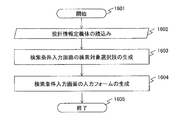
- FIG. 16 is a flowchart showing an example of processing of the design information search condition input screen output unit 203. This process is executed when the design information input / output device 102 receives a search request from the client device 103.
- the design information search condition input screen output unit 203 inputs the design information definition body 302 and the design information definition body 302, and outputs a search condition input screen 306a.
- step 1601 the design information search condition input screen output unit 203 starts processing in response to an instruction (search request) from the input unit 103b of the client device 103.
- the design information input / output device 102 receives a processing request from the input unit 103b via the communication interface unit 104b, and the design information search condition input screen output unit 203 generates a search condition input screen 306a.
- step 1602 the design information search condition input screen output unit 203 reads all the design information definition bodies 302 registered in the storage unit 102c.
- step 1603 the design information search condition input screen output unit 203 uses the value of the attribute “localName” of the element “designSpecification” (3023) of the read design information definition body 302 to “search target” of the generated search condition input screen 306 a. ”(3061).
- step 1604 when the “search target” (3061) in FIG. 9 is selected by the user, the design information search condition input screen output unit 203 designs that match the “search target” (3061) selected by the user.
- the information definition body 302 is specified. However, if “search target” is not selected by the user, this step is skipped.
- the design information search condition input screen output unit 203 designates the “search target” (3061) selected by the user as the design information definition body 302 having the value of the attribute “localName” of the element “designSpecification” (3023). Is identified.
- the design information search condition input screen output unit 203 generates, for each element “key” included in the specified design information definition body 302, an input form group having the value of the attribute “localName” of the element “key” as a name. .
- the design information search condition input screen output unit 203 includes the attribute “mandatory” of the element “singleItemKey” (3024) or the element “listItemKey” (3025) included in the element “key” in the generated input form group.
- an input form (3062, 3064) and a “search” (3063, 3065) button are generated for each value of the attribute “localName”.
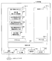
- FIG. 9 is a diagram showing an example of the search condition input screen 306a.
- the search condition input screen 306a generated by the design information search condition input screen output unit 203 includes a “search target” (3061) for selecting a search target from a pull-down list, items to be searched, and “search” buttons 3063 and 3065.
- search target (3061) for selecting a search target from a pull-down list, items to be searched, and “search” buttons 3063 and 3065.
- An example including two input forms 3062, 3064 including is shown.
- the value of the attribute “localName” of the element “key” is “class / method design information” and “class / method list” based on the design information definition body 302 shown in FIG.
- the design information search condition input screen output unit 203 includes the element “relationship” in the element “designSpecification” (3023) of FIG. 4 as the “search target” (3061) selected by the user.
- the design information search condition input screen output unit 203 displays the “parentItem” value and the “childItem” value.
- a single item group or a plurality of item groups specified in the above are grouped together to generate an input form group, an input form, and a “search” button.
- an element “relationship” attribute “parentItem” has a value of “classMethodDesignInfo” and a single item group “class / method design information (element“ key ”attribute“ localName ”
- the value of “class / method design information”, the value of attribute “name” is “classMethodDesignInfo”, and the value of attribute “type” is “single”).
- the design information search condition input screen output unit 203 has “classMethodList” as the value of the attribute “childItem” of the element “relationship” and the value of the attribute “localName” of the multiple item group “class / method list” (element “key” In the “Class / Method List”, the attribute “name” value is “classMethodList” and the attribute “type” value is “list”).
- a search condition input screen 306b having “method design information-class method list” is generated as shown in FIG.
- step 1605 the design information search condition input screen output unit 203 responds the processing response to the client device 103 via the communication interface unit 104b, and the search condition input screen 306a generated in step 1604 is output to the output unit 103d of the client device 103.
- the process ends after displaying 306b.
- FIG. 10 is a diagram showing an example of the search condition input screen 306b.
- the search condition input screen 306a generated by the design information search condition input screen output unit 203 includes a “search target” (3061) for selecting a search target from a pull-down list or the like, a search item, and a “search” button 3067.
- An example including two input forms 3066 is shown.
- an input form combining a single item and a plurality of items whose names are “class / method design information-class / method list”. Shows an example generated by the design information search condition input screen output unit 203.
- search condition input screens 306a and 306b shown in FIG. 9 or FIG. 10 are generated according to the contents of the design information definition body 302, and the user of the client apparatus 103 assigns a desired value to the search item in the input form.
- the search can be executed by inputting and then pressing the “Search” button.
- FIG. 17 is a flowchart illustrating an example of processing performed in the design information search and result display screen output unit 204.
- the design information search and result display screen output unit 204 inputs the design information definition body 302 and the design information 310, executes design information search using the items of the input form received in FIG. 9 or FIG. Is output as a design information search result screen 307. This process is executed after the “search” buttons 3063, 3065, 3067 are clicked on the search condition input screens 306a, 306b.
- step 1701 the “search” button is clicked on the search condition input screens 306a and 306b, and an instruction (search execution) is generated from the input unit 103b of the client apparatus 103.
- This instruction is used as a design information search and result display screen output unit.
- the design information search and result display screen output unit 204 accepts a processing request passed from the input unit 103b via the communication interface unit 104b, and the search condition (input form) input on the search condition input screens 306a and 306b.
- the design information 310 is searched using the design information definition body 302 using the search item as a search key. That is, the design information search and result display screen output unit 204 searches the file type of the design information 310 according to the search condition.
- the search range is determined by the design information search and result display screen output unit 204 in units of groups of input forms where the “search” button is clicked. For example, in the search condition input screen 306a of FIG. 9, when a search condition in the input form 3062 is input by “class / method design information” which is a group of input forms and the “search” button 3063 is clicked, design information definition In the body 302, the design information search and result display screen output unit 204 identifies the element “key” having the attribute “localName” having “class / method design information”. The design information search and result display screen output unit 204 acquires the value “classMethodDesignInfo” of “name” of the identified element “key” and uses the acquired value as the value of the attribute “name”. The storage unit 102c is searched in the range of “singleItems”.
- search condition input screen 306a when a search condition is input in the input form 3064 of the “class / method list” that is a group of input forms and the “search” button 3065 is clicked, design information search and result display are performed.
- the screen output unit 204 identifies an element “key” having a value of “class / method list” as the attribute “localName” in the design information definition body 302.
- the design information search and result display screen output unit 204 acquires the “name” value “classMethodList” of the identified element “key”, and the design information element “name” has the acquired value as the attribute “name” value.
- the storage unit 102c is searched in the range of “listItems” (3037).
- the search condition is input on the input form 3066 of the “class / method design information-class / method list” as the input form group, and the “search” button 3067 is clicked.
- the design information search and result display screen output unit 204 adds the element “key” whose attribute “localName” value has “class / method design information” or “class / method list” in the design information definition body 302. Identify.
- the design information search and result display screen output unit 204 acquires the value “classMethodDesignInfo” or the value “classMethodList” of the specified element “key”, and uses these acquired values as the value of the attribute “name”.
- the storage unit 102c is searched in the range of the elements “singleItems” and “listItems” of the design information 310 held by the user.
- step 1703 the design information search and result display screen output unit 204 acquires the file type of the design information 310 searched in step 1702, that is, the value of the attribute “name” of the element “documentCls” of the design information 310.
- step 1704 the design information search and result display screen output unit 204 reads the design information definition body 302 having the value acquired in step 1703 in the attribute “name” of the element “genericRule” from the storage unit 102c.
- step 1705 the design information search and result display screen output unit 204 uses the design information 310 acquired in step 1702 and the design information definition body 302 acquired in step 1704, and the design information search results shown in FIGS.
- the screen 307a, 307b or 307c is generated.
- the search range of the design information search result screens 307a to 307c shown in FIGS. 11A to 12 is the range searched in step 1702, and the input form to which the “search” buttons 3063 to 3067 clicked on the search condition input screens 306a to 306b belong. Depends on the group.
- the display screen output unit 204 searches a range of “class / method design information” corresponding to the value of the attribute “name” of the element “singleItems” of the design information.
- the design information search and result display screen output unit 204 generates a “class / method design information search result screen” 307a shown in FIG.
- the column header 3071 of the list of the “class / method design information search result screen” 307a includes “reference to design information” (3072) and the local name corresponding to the element name included in the element “singleItems”.
- the attribute “name” of the element “singleItemKey” of the design information definition body 302 is specified, and the value of the attribute “localName” is assigned.
- the design information search and result display screen output unit 204 generates a “class / method list search result screen” 307b shown in FIG.
- the column header 3071 of the list includes “design information reference” (3072), a local name corresponding to the element name included in the element “member”, and an attribute “name” of the element “listItemKey” of the design information definition body 302.
- the design information search and result display screen output unit 204 identifies and assigns a value of the attribute “localName”.
- the search condition input screen 306b when a search condition is input in the input form 3066 of the input form group “class / method design information-class / method list” and the “search” button 3067 is clicked, design information search is performed.
- the result display screen output unit 204 sets the “class / method design information” corresponding to the value of the attribute “name” of the element “singleItems” of the design information and the value of the attribute “name” of the element “listItems”. Search the corresponding "class / method list” range.
- the design information search and result display screen output unit 204 generates a “class / method list search result screen” 307c in the form of these search results.
- the design information search and result display screen output unit 204 assigns a “design information reference” (3072) and a local name corresponding to the element name included in the element “singleItems” to the column header 3071 of the list.
- the attribute “name” of the element “singleItemKey” 302 is identified, the value of the attribute “localName”, and the local name corresponding to the element name included in the element “member” are stored in the element “listItemKey” of the design information definition body 302.
- the attribute “name” is specified and the value of the attribute “localName” is assigned.
- the value of “design information reference” (3072) in any of the above-described design information search result screens 307a, 307b, and 307c is a button for transitioning to the design information reference and editing screen 308, and is displayed in the design information of each row of the list.
- the corresponding design document file name that is, the value of the attribute “fileName” of the element “documentCls” of the design information 310 is held.
- the design information search and result display screen output unit 204 finally returns a process response to the client device 103 via the communication interface unit 104b in step 1706, and the design information generated in step 1705 in the output unit 103d of the client device 103.
- the search result screens 307a to 307c are displayed and the process is terminated.
- the design information input / output device 102 can output the search results based on the search conditions received from the client device 103 as the design information search result screens 307a, 307b, 307c.
- the design information input / output device 102 searches the XML design information 310 file using the received search conditions. That is, even if the layout and items of the design document 304b are changed, the design information input / output device 102 can search for the XML-format design information 310 file. Therefore, unlike the conventional example, it is not necessary to modify the database in accordance with the layout or item change of the design document 304b, and the labor and operation cost associated with the change of the design document 304b can be reduced.
- FIG. 18 is a flowchart showing an example of processing of the design information reference and edit screen output unit 205. This process is executed when “design information reference” (3072) on the design information search result screens 307a to 307c is clicked.
- the design information reference / edit screen output unit 205 receives the design information definition body 302 and the design information 310 and outputs the design information reference / edit screen 308.
- step 1801 the “design information reference” (3072) button displayed on the design information search result screen 307a, 307b, or 307c is clicked, and an instruction is generated from the input unit 103b of the client apparatus 103. Processing begins.
- the design information reference and edit screen output unit 205 includes the design document file name assigned to the “design information reference” (3072) button in the value of the attribute “fileName” of the element “documentCls” (3031).
- the information 310 is retrieved from the storage unit 102c.
- step 1803 the design information reference and edit screen output unit 205 acquires the file type of the design information 310 read in step 1802, that is, the value of the attribute “name” of the element “documentCls” (3031) of the design information 310.
- Step 1804 the design information definition body 302 having the attribute “name” of the element “genericRule” (3021) as the attribute “name” of the element “genericRule” (3021) is read from the storage unit 102c.
- step 1805 the design information reference and edit screen 308 shown in FIG. 13 is used by using the design information definition body 302 read in step 1804 for the design information 310 acquired in step 1802 by the design information reference and edit screen output unit 205. Is generated.
- the design information reference / edit screen output unit 205 corresponds to the value of the attribute “name” of the element “documentCls” (3031) of the design information 310 as the “file type” (3081) of FIG.
- the value of the attribute “localName” of the element “documentCls” of the design information definition body 302 and the value of the attribute “fileName” of the element “documentCls” (3031) are generated as “file name” (3082).
- the design information reference / edit screen output unit 205 performs the design in step 1804 corresponding to the value of the attribute “name” of the element “sheetCls” of the design information 310 as “sheet type” (3084) in the “file type” (3081). A value of the attribute “localName” of the element “sheetCls” of the information definition body 302 is generated.
- the design information reference and edit screen output unit 205 generates the value of the attribute “date” of the element “documentCls” within the “registration date” (3083). Further, a single item group and a plurality of item groups are generated in the “sheet type” (3084).
- the design information reference and edit screen output unit 205 sets the element value included in the element “singleItems” (3033) as an uneditable text on the design information reference and edit screen 308, or editable input. Whether the field is a field is determined by the value of the element “itemType” of the corresponding design information definition body 302, and the design information reference and edit screen 308 is generated.
- the design information reference and edit screen output unit 205 stores the element “key” of the design information definition body 302 read in step 1804 corresponding to the value of the attribute “name” of the element “listItems” (3037).
- the value of the attribute “localName”, the element included in the element “member” included in the element “listItems” (3037), and the value thereof are generated in a list format.
- the design information reference and edit screen output unit 205 sets the local name corresponding to the element name included in the element “member” in the column header 3085 of the list, and the attribute of the element “listItemKey” (3025) of the design information definition body 302. Specify “name” and assign the value of attribute “localName”.
- the design information reference and editing screen output unit 205 determines whether the value to be listed is a text that cannot be edited or an input field that can be edited on the screen.
- the design information reference and edit screen 308 is generated by determining with the value of “itemType”.
- the size of the area for displaying the values listed in the design information reference / edit screen 308 is the value of the element “itemLength” of the design information definition body 302 to which the design information reference / edit screen output unit 205 corresponds. Determine and generate a screen. When the “Add” (3086) button on the design information reference and edit screen 308 is clicked, a new line can be added to the list.
- step 1806 the design information reference / edit screen output unit 205 returns a processing response to the client device 103 via the communication interface unit 104b, and the design information generated in step 1705 is referred to the output unit 103d of the client device 103. Then, the editing screen 308 is displayed and the processing is terminated.
- the design information input / output device 102 can read the design information 310 in the XML format and display it as the design information reference and edit screen 308.
- FIG. 19 is a flowchart showing an example of processing of the design information editing processing unit 206.
- the design information edit processing unit 206 receives the design information definition body 302, the design information template 303, the design information 310, and the design document template 304a as input, and the design information 310 (FIG. 6) edited on the design information reference and edit screen 308.
- the design document 304c (FIG. 7C) is output.
- step 1901 when the “registration / design document output” (3088) button displayed on the design information reference and edit screen 308 is clicked, an instruction is generated from the input unit 103 b of the client apparatus 103, and the process is triggered by this instruction. Is started.
- the design information editing processing unit 206 has a design information definition having the “file type” (3081) value of the design information reference and edit screen 308 as the attribute “localName” value of the element “genericRule” (3021).
- the body 302 is read from the storage unit 102c.
- the design information editing processing unit 206 stores the “file type” (3081) of the design document meta information 301 read in step 1902 from the files of the design document meta information 301 registered in the storage unit 102c.
- the design information template 303 file having the same value as the “alphabetic name” as the value of the attribute “name” of the element “documentCls” of the design information template 303 is read from the storage unit 102c.
- step 1904 the design information editing processing unit 206 first sets the “file name” (3082) of the design information reference and edit screen 308 to the value of the attribute “fileName” of the element “documentCls” (3031) of the design information template 303. Set.
- the design information editing processing unit 206 reads the value of a single item or a plurality of items from the design information reference and edit screen 308 and substitutes it into a predetermined variable. Then, the design information 310 in the XML format is generated by setting the value of the variable in the design information template 303 read in step 1903.
- the design information editing processing unit 206 receives the element “singleItemKey” (3024) or the element “listItemKey” (3024) of the design information definition body 302 read in step 1902 corresponding to a single item or a plurality of items from the design information reference and edit screen 308. 3025) When the value of the attribute “mandatory” is “true”, but the value of the single item or multiple items is not input on the design information reference and edit screen 308, or is not deleted Output an error.
- the design information editing processing unit 206 When the value of the attribute “type” of the element “key” of the design information definition body 302 is “single” for the single item, the design information editing processing unit 206 has the element “singleItemKey” (3024) of the design information definition body 302 A value having the same name as the attribute “localName” in the header is acquired from the design information reference and edit screen 308. The design information editing processing unit 206 uses the acquired value as the value of the attribute “sheetCls” of the element “designSpecification” (3023), the value of the attribute “name” of the element “key”, and the element of the design information definition body 302.
- a variable is generated in a format in which the value of the attribute “name” of “singleItemKey” (3024) is concatenated with “.”, And the value is substituted. The above process is repeated by the number of elements “singleItemKey” of the design information definition body 302.
- the design information editing processing unit 206 When the value of the attribute “type” of the element “key” of the design information definition body 302 is “list” for a plurality of items, the design information editing processing unit 206 has an element “listItemKey” (3025) of the design information definition body 302 A plurality of values of the column having the same name as the attribute “localName” in the list header are acquired from the design information reference and edit screen 308.
- the design information editing processing unit 206 uses the acquired value as the value of the attribute “sheetCls” of the element “designSpecification” (3023) of the design information definition body 302 and the value of the attribute “name” of the element “key”. Variables are generated in a format concatenated with "". This variable is a list object, and a value obtained from the design information reference and edit screen 308 by creating a variable whose name is the value of the attribute “name” of the element “listItemKey” (3025) of the design information definition body 302 Register.
- the design information editing processing unit 206 generates the design information 310 by replacing the value of the variable generated as described above with the corresponding value of the “$” variable in the design information template 303. It should be noted that the processing of the portion surrounded by “#foreach (each $ member in $ XXXX)” and “#end” in the design information 310 is the same as the processing in step 1507 above.
- the design information edit processing unit 206 generates the edited XML format design information 310 from the design information reference and edit screen 308.
- the design information editing processing unit 206 stores the design information 310 generated in step 1904 in the storage unit 102c, and updates the design information 310 with the edited data.
- the design information editing processing unit 206 can store the XML-format design information 310 in one column of the database.
- step 1906 the design information editing processing unit 206 uses the design file template 304a stored in advance for each file type in the storage unit 102c as the “file type” (3081) value on the design information reference and edit screen 308. And read from the storage unit 102c.
- step 1907 the design information editing processing unit 206 uses the design information definition body 302 read in step 1902 to update the design document template 304a read in step 1906 from the design information 310 generated in step 1904.
- a design document 304c reflecting the design information 310 edited on the design information reference and edit screen 308 is generated.
- the design information editing processing unit 206 uses the element “key” of the design information definition body 302 having the same value as the value of the attribute “name” of the element “singleItems” (3033) of the design information 310.
- the element “singleItemKey” (3024) having the same value as the value of each element included in the element “singleItems” (3033) of the design information 310 in the attribute “name” (within the specified element “key”) Is identified.
- Each element included in the element “singleItems” (3033) of the design information 310 is acquired from the element “cellLine” in the element “singleItemKey” (3024) and the spreadsheet column is acquired from the element “cellColumn”. Is reflected in the cell specified by the row and column acquired in the design template template 304a read in step 1906.
- the design information editing processing unit 206 identifies the element “key” of the design information definition body 302 having the same value as the value of the attribute “name” of the element “listItems” (3037) of the design information 310. To do. Then, the design information editing processing unit 206 has an element “listItemKey” (within the specified element “key”) having the same value as the value of each element included in the element “member” of the design information 310 (within the specified element “key”). 3025).
- the design information editing processing unit 206 acquires the spreadsheet row from the element “cellLine” in the element “listItemKey” (3025) and the spreadsheet column from the element “cellColumn”, and the element “member” of the design information 310. The value of each element included in is reflected in the cell specified by the row and column acquired in the design template template 304a read in step 1906.
- the design information editing processing unit 206 adds the date, time, day, minute, and second of this process to the value of the attribute “date” of the element “documentCls” (3031) of the design information 310, for example “YYYY / MM / DD / HH: Set in the format of “MM: SS”.
- step 1908 the design information editing processing unit 206 stores the design document 304c generated in step 1907 in the storage unit 102c, performs data transfer processing via the communication interface unit 104b, and stores it in the storage unit 103c of the client device 103. sign up.
- the design information editing processing unit 206 may edit the design document 304c generated in step 1907 with the spreadsheet unit 211 on the client device 103, for example, and use this as the design document 304b.
- the design information editing processing unit 206 finally outputs a message indicating that the processing has been completed to the output unit 103d in step 1908.
- the design information 310 edited on the design information reference and edit screen 308 is stored in the storage unit 102c as XML data, and the design information 310 is converted into a spreadsheet design document 304c and sent to the client apparatus 103. Is output.
- the first embodiment it is possible to realize a spreadsheet-style design document input / output system 100 that can flexibly cope with various design documents created in system development and can be easily customized.
- the design information 310 may be stored as an XML file, stored in one column of the database, or stored in the XML database. Good.
- the design document 304b is in the XML format, but if it is a semi-structured data format similar to XML (Extensible Markup Language), JSON (JavaScript Object Notation). Or the like.
- the spreadsheet format is information generated by the spreadsheet units (spreadsheet software) 210 and 211, and may be configured to include cells having row and column identifiers and sheets having a plurality of cells.
- the design document 304b of a spreadsheet format is converted into an XML format, edited, and searched If it is.
- the design document 304b of the first embodiment may be replaced with input information
- the design information definition body 302 may be replaced with an input information definition body
- the design information template 303 may be replaced with a conversion information template.
- FIG. 21 is a block diagram illustrating an example of functional elements of the computer 10 according to the second embodiment.
- the second embodiment shows an example in which the design information input / output device 102 shown in the first embodiment is operated on the computer 10 as a virtual server.
- Other configurations are the same as those of the first embodiment.
- a virtualization unit 400 that provides computer resources to a virtual server operates, and one or more guest OSs 710-1 to 710-x operate on the virtualization unit 400.
- the guest OS 710-1 provides a design information input / output server 102-1
- the guest OS 710-x provides a virtual server 102-x.
- the virtualization unit 400 and the guest OSs 710-1 to 710 -x are loaded into the memory 70 of FIG. 20 allocated by the virtualization unit 400 and executed by the processor 60.
- the virtualization unit 400 provides the guest OSs 710-1 to 710-x with the input unit 102b, the storage unit 102c, the output unit 102d, and the communication interface unit 104b, which are computer resources of the computer 10.
- the design document reading conversion unit 202 On the guest OS 710-1, the design document reading conversion unit 202, the design information search condition input screen output unit 203, the design information search and result display screen output unit 204, the design information A reference and edit screen output unit 205 and a design information edit processing unit 206 are operated.
- the design document reading conversion unit 202 to the design information editing processing unit 206 provide the functions of the respective units when the processor 60 executes the respective programs, as in the first embodiment.
- the client apparatus 103 connected via the network 40 can use each function of the design information input / output server 102-1 via the browser 212.
- the browser 212 reads the design document read conversion unit 202 of the design information input / output server 102-1, and registers the design document 304b.
- the client apparatus 103 transmits the design document 304b to the design information input / output server 102-1, and the design information input / output server 102-1 stores the received design document 304b in the storage unit 102c.
- the design document read conversion unit 202 reads the design information definition body 302 and the design information template 303 corresponding to the design document 304b stored in the storage unit 102c, converts the design information template 303 into the XML design information 310, and stores it in the storage unit 102c. .
- the virtualization unit 400 may generate the design information input / output server 102-1 in response to a request from the client device 103.
- the computer resources of the computer 10 can be used effectively.
- design document meta information conversion apparatus 101 and the client apparatus 103 shown in the first embodiment may be virtual servers on the computer 10.
- the design information input / output server 102-1 may be operated in a cloud system having a plurality of computers 10.
- the design information 310 in the XML format is stored in the storage unit 102c as an XML file, stored in one column (or one field) of the database storing the design information 310, or stored in the above-described XML database format or the like. Since it can be stored in the apparatus, it is not necessary to change the schema of the database even when the layout of the design document is changed.
- the spreadsheet format design document 304b is converted into the XML format design information 310 and stored in the storage unit 102c.
- the layout of the design document 304b is changed, it is not necessary to modify the file or database for storing the design information 310, and the labor and operation costs associated with the change of the design document 304b are reduced as compared with the conventional example. Can be reduced.
- the design document meta information conversion device 101 changes the design document meta information 301 to reproduce the design information definition body 302 and the design information template 303. And transmitted to the design information input / output device 102.
- the design information input / output device 102 uses the regenerated design information definition body 302 and the design information template 303 to convert the spreadsheet format design document 304b input as described above into the XML format and store the storage unit 102c. Can be stored.
- the design information input / output device 102 also stores screens and processes for searching and editing the design information 310 by storing the regenerated design information definition body 302 and the design information template 303 in the storage unit 102c.
- the design information 310 that can be automatically changed, edited, and re-stored can be output as a design document 304c in a spreadsheet format.
- the present invention can flexibly cope with various design documents created or updated in system development, and the spreadsheet design document input / output system 100 that allows easy customization of the design document. Can be provided.
- this invention is not limited to the above-mentioned Example, Various modifications are included.
- the above-described embodiments are described in detail for easy understanding of the present invention, and are not necessarily limited to those having all the configurations described.
- a part of the configuration of one embodiment can be replaced with the configuration of another embodiment, and the configuration of another embodiment can be added to the configuration of one embodiment.
- any of the additions, deletions, or substitutions of other configurations can be applied to a part of the configuration of each embodiment, either alone or in combination.
- each of the above-described configurations, functions, processing units, processing means, and the like may be realized by hardware by designing a part or all of them with, for example, an integrated circuit.
- each of the above-described configurations, functions, and the like may be realized by software by the processor interpreting and executing a program that realizes each function.
- Information such as programs, tables, and files for realizing each function can be stored in a memory, a hard disk, a recording device such as an SSD (Solid State Drive), or a recording medium such as an IC card, an SD card, or a DVD.
- control lines and information lines indicate what is considered necessary for the explanation, and not all the control lines and information lines on the product are necessarily shown. Actually, it may be considered that almost all the components are connected to each other.
Abstract
プロセッサとメモリを備えてスプレッドシート形式の設計書を処理する設計書の入出力装置であって、予め生成されて前記設計書の構造を定義した設計情報定義と、予め生成されてスプレッドシート形式の前記設計書を半構造データ形式に変換する定義を有する設計情報雛形と、を格納する記憶部と、前記スプレッドシート形式の前記設計書を受信して、当該設計書の情報を前記設計情報定義に基づいて前記設計情報雛形に設定し、前記半構造データ形式の設計情報として出力する変換部と、を有する。
Description
本出願は、平成28年(2016年)2月19日に出願された日本出願である特願2016-030214の優先権を主張し、その内容を参照することにより、本出願に取り込む。
本発明は、例えばシステム開発等で作成及び保守される様々なレイアウトの設計書を、記憶装置で一元管理する目的で、スプレッドシートソフトで作成して記憶装置に入出力する技術に関するものである。
システム開発では、計算機システムを構成する画面やデータベースに関する設計情報を記すために様々な設計書が作成される。設計書はワードプロセッシングソフトやスプレッドシート(表計算)ソフトなどで作成されるが、本発明ではスプレッドシート形式の設計書を対象とする。
設計書はシステム開発者間で設計情報を共有するためのメディアである。他方、設計書に記される設計情報を活用してプログラムの自動生成など機械的な処理を行うために、設計書を構造分析した上でデータベースの形式に設計情報を変換して一元管理する。
このようなスプレッドシートで記されるデータとデータベースのデータとの入出力を機械化する装置として特許文献1が知られている。
上述の従来技術では、スプレッドシートで記されるデータとデータベースのデータとの入出力を機械化することはできるが、データベースにデータを格納するためのスキーマを事前に定義しておく必要があった。
システム開発で取り扱われる設計書は、開発プロジェクトごとに種類や記述する項目やレイアウトが異なり、また開発や保守の過程でレイアウトや項目が変更されることもある。従来技術では、データベースのスキーマの変更、及びスキーマの変更に伴うデータマイグレーションが必要とされる。また、設計書をデータベースに集約して設計情報を一括で保守するために、スキーマに則ってデータベースで格納されている設計情報の検索や編集をする画面や処理が作成されることがある。この場合、スキーマの変更に伴いそれらの画面や処理の改修も必要となる、という問題があった。
そこで本発明は、上記問題点に鑑みてなされたもので、設計書に記述される項目やレイアウトが変更になった場合にデータベースのスキーマの改修を不要にすることを目的とする。
本発明は、プロセッサとメモリを備えてスプレッドシート形式の設計書を処理する設計書の入出力装置であって、予め生成されて前記設計書の構造を定義した設計情報定義と、予め生成されてスプレッドシート形式の前記設計書を半構造データ形式に変換する定義を有する設計情報雛形と、を格納する記憶部と、前記スプレッドシート形式の前記設計書を受信して、当該設計書の情報を前記設計情報定義に基づいて前記設計情報雛形に設定し、前記半構造データ形式の設計情報として出力する変換部と、を有する。
本発明によれば、システム開発においてスプレッドシート形式で作成される設計書を半構造データ型式(例えば、XML形式)の設計情報に変換することが可能となる。XML形式の設計情報は、XMLファイルとして格納するか、またはデータベースの一カラムに格納する、あるいはXMLデータベースなどの形式で記憶装置に格納できるため、設計書のレイアウトが変更された場合であってもデータベースのスキーマの変更は不要となる。これによりシステム開発において作成される様々な設計書に柔軟に対応可能であり、設計書のカスタマイズが容易なスプレッドシート形式設計書の入出力を実現できる。
本発明の一実施例について、以下図面を参照して説明する。なお、同一の符号は同一の構成要素を示す。
<装置構成>
本発明の実施例1に係る計算機システムは、設計書メタ情報変換装置101と、設計情報入出力装置102と、クライアント装置103からなるスプレッドシート形式の設計書の入出力システム100である。図1は、計算機システムのハードウェア構成の一例を示すブロック図を示す。
本発明の実施例1に係る計算機システムは、設計書メタ情報変換装置101と、設計情報入出力装置102と、クライアント装置103からなるスプレッドシート形式の設計書の入出力システム100である。図1は、計算機システムのハードウェア構成の一例を示すブロック図を示す。
設計書メタ情報変換装置101と、設計情報入出力装置102と、クライアント装置103は、図1に示すように、制御及び演算部101aと102aと103aと、入力部101bと102bと103b、記憶部101cと102cと103cと、出力部101dと102dと103dと、通信インタフェース部104aと104b及び104cを有する計算機システムである。なお、通信インタフェース部104a、104b及び104cはネットワークを介して接続される。
設計書メタ情報変換装置101と設計情報入出力装置102は、通信インタフェース部104aと104bを介して互いの装置間のデータ通信連携を実現する。設計情報入出力装置102とクライアント装置103は、通信インタフェース部104bと104cを介して互いの装置間のデータ通信を実現する。これらの、設計書メタ情報変換装置101と、設計情報入出力装置102と、クライアント装置103は、一体であっても構わない。
記憶部101cと102cと103cは、ハードディスクドライブ等の不揮発性の記憶媒体を含む記憶装置で構成される。設計書メタ情報変換装置101の記憶部101cには設計書メタ情報変換部201と表計算部210として機能するコンピュータソフトウェアプログラムが格納される。
設計情報入出力装置102の記憶部102cには設計書読込及び変換部202と設計情報検索条件入力画面出力部203と設計情報検索及び結果表示画面出力部204と設計情報参照及び編集画面出力部205と設計情報編集処理部206として機能するコンピュータソフトウェアプログラムが格納されている。
クライアント装置103の記憶部103cには設計書などを編集する表計算部211として機能するコンピュータプログラムと、ブラウザ212として機能するコンピュータプログラムと、スプレッドシートの設計書及び設計書の雛形が格納されている。また、記憶部103cには設計情報入出力装置102から送信された画面を出力部103dに表示するブラウザとして機能するコンピュータソフトウェアプログラムも格納されている。
制御及び演算部101a、102a、103aは、後述するようにプロセッサとメモリを含み、記憶部101c、102c、103cからプログラムをメモリにロードしてプロセッサによって実行する。
設計書メタ情報変換部201及び表計算部210は、制御及び演算部101aによって記憶部101cから読み出されて実行されることにより各機能を実現している。設計書読込及び変換部202と設計情報検索条件入力画面出力部203と設計情報検索及び結果表示画面出力部204と設計情報参照及び編集画面出力部205は制御及び演算部102aによって記憶部102cから読み出されて実行されることにより各機能を実現している。表計算部211及びブラウザ212は、制御及び演算部103aによって記憶部103cから読み出されて実行されることにより各機能を実現している。
入力部101bと102bと103bは、マウス等の入力デバイスである。出力部101dと102dと103dは、各種ディスプレイ等の表示デバイスであり、この他各種プリンタ等の他の出力装置を接続することもできる。
図20は、スプレッドシート形式の設計書入出力システム100を構成する計算機の一例を示すブロック図である。図示の例は、設計書メタ情報変換装置101として稼動する計算機10の例を示すが、設計情報入出力装置102及びクライアント装置103も同様の構成である。
計算機10は、制御及び演算処理を行うプロセッサ60と、プログラムやデータを保持するメモリ70と、ネットワーク40に接続されて他の計算機等と通信を行う通信インタフェース部104aと、記憶部101cに接続されてデータやプログラム等の読み書きを行うストレージインタフェース86と、入力部101bに接続されたI/Oプロセッサ83と、プロセッサ60に接続された出力部101dを含む。なお、図1に示した制御及び演算部101a、102a、103aは、プロセッサ60及びメモリ70に相当する。
プロセッサ60は、ヘテロジニアスのマルチコアプロセッサで構成され、複数のCPUコア61と、複数のGPUコア62を含む。また、プロセッサ60は、メモリ70に接続されるメモリコントローラ63と、出力部101dに接続されるディスプレイコントローラ65と、I/Oプロセッサ83、通信インタフェース部104a及びストレージインタフェース86に接続されるI/Oコントローラ64とを含む。入力部101bとしては、キーボードやマウスやタッチパネルを含む。出力部101dとしては、ディスプレイを含む。
メモリ70には、OS71がロードされてプロセッサ60によって実行される。OS71は設計書メタ情報変換部や表計算部などの1以上のソフトウェア72を実行する。
設計書メタ情報変換部201などの各機能部はプログラムとしてメモリ70にロードされる。
プロセッサ60は、各機能部のプログラムに従って処理することによって、所定の機能を提供する機能部として稼働する。例えば、プロセッサ60は、設計書メタ情報変換プログラムに従って処理することで設計書メタ情報変換部201として機能する。他のプログラムについても同様である。さらに、プロセッサ60は、各プログラムが実行する複数の処理のそれぞれの機能を提供する機能部としても稼働する。計算機及び計算機システムは、これらの機能部を含む装置及びシステムである。
設計書メタ情報変換装置101の各機能を実現するプログラム、テーブル等の情報は、記憶部101cや不揮発性半導体メモリ、ハードディスクドライブ、SSD(Solid State Drive)等の記憶デバイス、または、ICカード、SDカード、DVD等の計算機読み取り可能な非一時的データ記憶媒体に格納することができる。
<処理の概要>
図2は、計算機システムの機能ブロック図の一例を示す。
図2は、計算機システムの機能ブロック図の一例を示す。
本実施例1では、設計書メタ情報変換装置101を利用する開発者等が、クライアント装置103を利用するユーザの業務を処理する計算機システムを開発することを想定する。設計情報入出力装置102は、ユーザの業務で使用する設計書を処理する計算機である。
設計書メタ情報変換装置101は、開発者の操作に応じて、設計書304b(図7B)の構造(項目及びレイアウト)を定義する設計書メタ情報301(図3)をスプレッドシート形式で生成する。
設計書メタ情報変換装置101では、設計書メタ情報変換部201が、設計書メタ情報301を読み込んで、設計書304bの構造を定義する設計情報定義体302(図4)と、設計書304bを変換する際に利用する設計情報雛形303(図5)に変換する。
設計書メタ情報変換装置101は、変換された設計情報定義体302と設計情報雛形303を、ユーザが利用する設計情報入出力装置102の記憶部102cへ格納させる。
また、設計書メタ情報変換装置101を利用する開発者は、設計書メタ情報301に対応する設計書雛形304a(図7A)を生成して、ユーザが利用する設計情報入出力装置102の記憶部102cに格納しておく。
クライアント装置103のユーザは、表計算部210で設計書雛形304aを読み込んで、スプレッドシート形式の設計書304bを生成し、記憶部102cに格納する。
クライアント装置103はユーザの操作に応じて、設計書304bの登録を要求する。設計書メタ情報変換部201は、登録要求を受け付けると設計書登録画面305をクライアント装置103に出力する。
クライアント装置103は設計書登録画面305から設計書304bの登録を実行する。設計情報入出力装置102は、スプレッドシート形式の設計書304bを受け付けると、設計書読込及び変換部202が設計情報定義体302と、設計情報雛形303を読み込んで、後述するようにスプレッドシート形式の設計書304bをXML形式の設計情報310に変換し、記憶部102cに格納する。
設計情報入出力装置102は、クライアント装置103から検索要求を受け付けると、設計情報検索条件入力画面出力部203が設計情報定義体302を読み込んで検索条件入力画面306を生成し、クライアント装置103に出力する。なお、検索条件入力画面306は、図9、図10の検索条件入力画面306a、306bの総称を示す。
設計情報入出力装置102は、クライアント装置103から検索項目を受け付けると、設計情報検索及び結果表示画面出力部204が検索を実行して、設計情報定義体302を参照して設計情報検索結果画面307を生成し、検索結果としてクライアント装置103に送信する。なお、設計情報検索結果画面307は、図11A~図12に示す設計情報検索結果画面307a、307b、307cの総称である。
設計情報入出力装置102は、クライアント装置103から検索結果について設計情報の参照要求を受け付けると、設計情報参照及び編集画面出力部205が設計情報310と設計情報定義体302を読み込んで、設計情報参照及び編集画面308を生成し、クライアント装置103に出力する。
クライアント装置103は、設計情報参照及び編集画面308から設計情報310の編集を行うことができる。設計情報入出力装置102は、クライアント装置103から編集結果の出力要求を受け付けると、設計情報編集処理部206がXML形式の設計情報310を読み込んで、設計情報定義体302と設計情報雛形303に応じてスプレッドシート形式の設計書304cを生成してクライアント装置103へ送信する。
<データ構成>
スプレッドシート形式で作成される各種設計書に対するメタ情報を定義した設計書メタ情報301について説明する。
スプレッドシート形式で作成される各種設計書に対するメタ情報を定義した設計書メタ情報301について説明する。
設計書メタ情報301は、設計書メタ情報変換装置101の記憶部101cに格納されたファイルの一例であり、設計書メタ情報変換部201で利用される。設計書メタ情報301は、スプレッドシートで定義される設計書の種別ごとに1つのファイルが表計算部210によって作成される。
以下、図3に一例を示す設計書メタ情報301を利用してデータ構成について説明する。設計書メタ情報301は、クライアント装置103で利用するスプレッドシート形式の設計書304b(設計書雛形304a)で使用する項目と、各項目のセルの位置等のレイアウトを定義した設計書304bの構造を定義したファイルである。
設計書メタ情報301の1ファイルの中には、“ファイル種別”(3011)と、“項目グループ間関連”(3012)と、“シート種別”(3013)と、“単数項目グループ”(3014)と、“複数項目グループ”(3015)の要素が含まれる。
要素“ファイル種別”(3011)はスプレッドシート形式のファイルごとに設計書の種別を定義するものであり、要素“ローカル名”と要素“英字名”を含む。
要素“シート種別”(3013)はスプレッドシートで定義されるシートごとに定義される。したがって、スプレッドシート内に複数のシートで構成される設計書304bを対象とする場合、要素“シート種別”(3013)、及び以下の“単数項目グループ”(3014)と、“複数項目グループ”(3015)を複数定義する。要素“シート種別”(3013)は、要素“ローカル名”と要素“英字名”を含む。
要素“単数項目グループ”(3014)には、設計書で定義される1つの項目に対して値が1つ定義される項目(単数項目)の内容と付加情報を定義するグループを定義する。なお、要素“単数項目グループ”(3014)は、要素“ローカル名”と要素“英字名”を含む。また、定義される単数項目の数だけ、要素“項番”と、要素“必須フラグ”と、要素“単数項目ローカル名”と、要素“単数項目英字名”と、単数項目がスプレッドシート上のどの位置にあるかを示す情報として要素“開始行”と要素“開始列”と、単数項目を画面上に表示する際に必要とする情報として要素“種類”と要素“サイズ”が定義される。
“種類”は、クライアント装置103のブラウザで表示する際の形式を規定し、“input”は入力フィールドを示し、“text”は文字列を表示することを示す。また、“サイズ”は、入力される文字数を規定する。
要素“複数項目グループ”(3015)には、設計書で定義される1つの項目に対して値が複数定義される項目(複数項目)の内容と付加情報を定義するグループを定義する。要素“複数項目グループ”(3015)は、要素“ローカル名”と要素“英字名”を含む。また、複数項目の数だけ、要素“項番”と、要素“必須フラグ”と、要素“複数項目ローカル名”と、要素“複数項目英字名”と、複数項目がスプレッドシート上のどの位置から始まるかを示す情報として要素“開始行”と要素“開始列”と、複数項目を画面上に表示する際に必要とする情報として要素“種類”と要素“サイズ”が定義される。
なお、以上の要素“単数項目グループ”(3014)と要素“複数項目グループ”(3015)は、対象とする設計書に合わせて、それぞれ無くてもよいし、複数あってもよい。
要素“項目グループ間関連”(3012)には、要素“項番”と、要素“親項目グループ名”と、要素“子項目グループ名”と、要素“説明”を含む。要素“親項目グループ名”と要素“子項目グループ名”には、“単数項目グループ”(3014)または“複数項目グループ”(3015)の“英字名”が記入される。
設計書メタ情報301は、上記の内容で記憶部101cに格納される。設計書メタ情報301は、クライアント装置103が利用する設計書304bに対応して設計書メタ情報変換装置101を使用する開発者などが予め作成してクライアント装置103へ送信する。設計書メタ情報301は、設計書メタ情報変換装置101で作成してもよいし、他の計算機で生成してもよい。
以上のように設計書メタ情報301は、スプレッドシート形式の設計書304b及び設計書雛形304aの構造とレイアウトを含む構成情報を予め定義した情報である。
図4に設計情報定義体302の一例を示す。設計情報定義体302は、設計書メタ情報変換部201の処理によって1つの設計書メタ情報301から1つ生成されて、記憶部101c及び記憶部102cに格納されるファイルである。以下、図4の設計情報定義体302を参照してデータの構成について説明する。
設計情報定義体302はXML形式のファイルであり、ルート要素として“genericRule”(3021)を持つ。また、要素“genericRule”(3021)は属性として“localName”と“name”を持つ。
“localName”の値は設計書メタ情報301の“ファイル種別”(3011)の“ローカル名”から、“name”の値は設計書メタ情報301の“ファイル種別”(3011)の“英字名”から、設計書メタ情報変換部201の処理でそれぞれ設定される。
さらに要素“genericRule”(3021)は、要素“relationship”(3022)と要素“designSpecification”(3023)を複数含む。
要素“relationship”(3022)は、設計書メタ情報301で定義される“項目グループ間関連”と同数だけ、設計書メタ情報変換部201の処理によって生成される。また、要素“relationship”(3022)は属性として“parentItem”と“childItem”を持つ。“parentItem”の値は設計書メタ情報301の“親項目グループ名”から、“childItem”の値は設計書メタ情報301の“子項目グループ名”から、設計書メタ情報変換部201の処理でそれぞれ設定される。
要素“designSpecification”(3023)は、設計書メタ情報301で定義される“シート種別”と同数だけ、設計書メタ情報変換部201の処理によって生成される。要素“designSpecification”(3023)は属性として“localName”と“sheetCls”を持つ。
“localName”の値は設計書メタ情報301の“シート種別”(3013)の“ローカル名”から、“sheetCls”の値は設計書メタ情報301の“シート種別”(3013)の“英字名”から、設計書メタ情報変換部201の処理でそれぞれ設定される。さらに要素“designSpecification”(3023)は、要素“key”を複数含む。
要素“key”は、設計書メタ情報301の“単数項目グループ”(3014)または“複数項目グループ”(3015)の数だけ、設計書メタ情報変換部201の処理によって生成される。また、要素“key”は属性として“localName”と“name”と“type”を持つ。
“localName”の値は設計書メタ情報301の“単数項目グループ”(3014)の“ローカル名”または“複数項目グループ”(3015)の“ローカル名”から設計書メタ情報変換部201の処理で設定される。“name”の値は設計書メタ情報301の“単数項目グループ”(3014)の“英字名”または“複数項目グループ”(3015)の“英字名”から設計書メタ情報変換部201の処理で設定される。
“type”の値は“単数項目グループ”(3014)の場合は“single”または“複数項目グループ”(3015)の場合は“list”から、設計書メタ情報変換部201の処理で設定される。さらに要素“key”は、“type”に設定された値が”single”の場合は要素“singleItemKey”を複数含み、または“type”に設定された値が“list”の場合は要素“listItemKey”を複数含む。
要素“singleItemKey”(3024)は、設計書メタ情報301の“単数項目グループ”(3014)で定義される項目の数だけ、設計書メタ情報変換部201の処理によって生成される。また、要素“singleItemKey”(3024)は属性として“localName”と“name”と“mandatory”を持つ。
“localName”の値は設計書メタ情報301の“単数項目グループ”(3014)の“単数項目ローカル名”から、“name”の値は設計書メタ情報301の“単数項目グループ”(3014)の“単数項目英字名”から、“mandatory”の値は設計書メタ情報301の“必須フラグ”に“○”が記入されている場合は“true”が、“必須フラグ”に何も記入されていない場合は“false”が、設計書メタ情報変換部201の処理でそれぞれ設定される。
さらに、要素“singleItemKey”(3024)は、要素“spreadsheet”と要素“webScreen”を含む。要素“listItemKey”(3025)は、設計書メタ情報301の“複数項目グループ”(3015)で定義される項目の数だけ、設計書メタ情報変換部201の処理によって生成される。また、要素“listItemKey”(3025)は属性として“localName”と“name”と“mandatory”を持つ。
“localName”の値は設計書メタ情報301の“複数項目グループ”(3015)の“複数項目ローカル名”から、“name”の値は設計書メタ情報301の“複数項目グループ”(3015)の“複数項目英字名”から、“mandatory”の値は設計書メタ情報301の“必須フラグ”に“○”が記入されている場合は“true”が“必須フラグ”に何も記入されていない場合は“false”が、設計書メタ情報変換部201の処理でそれぞれ設定される。さらに、要素“listItemKey”(3025)は、要素“spreadsheet”と要素“webScreen”をそれぞれ1つずつ含む。
必須フラグは設計書304bで必ず使用する項目を識別するフラグで、“○”であれば設計書304bで必須の項目であることを示す。また、必須フラグが“○”に設定された項目は、検索処理で検索キーとなる。
要素“sheet”(3026)は、要素“cellLine”と要素“cellColumn”をそれぞれ1つずつ含む。要素“cellLine”(3026)の値は設計書メタ情報301の“開始行”から、要素“cellColumn”の値は設計書メタ情報301の“開始列”から、設計書メタ情報変換部201の処理でそれぞれ設定される。
要素“webScreen”(3027)は、要素“itemType”と、要素“itemLength”を、それぞれ1つずつ含む。要素“itemType”の値は設計書メタ情報301の“種類”から、要素“itemLength”の値は設計書メタ情報301の“サイズ”から、設計書メタ情報変換部201の処理でそれぞれ設定される。
以上のように、設計情報定義体302には、スプレッドシート形式の設計書304bの行番号(cellLine)と列番号(cellColumn)で定まるセルの情報が定義される。設計書読込変換部202は、設計書304bに応じた設計情報定義体302を参照することで、スプレッドシート形式の設計書304bの構造を取得できる。
図5にスプレッドシート形式の設計書304bをXML形式に変換するために使用する設計情報の雛形、または記憶部102cに格納された設計情報310をXML形式に再変換するために使用する設計情報雛形303の一例を示す。
設計情報雛形303は、設計書メタ情報変換部201の処理によって設計書メタ情報301を元にして生成され、記憶部101c及び102cに格納されるファイルである。以下、図5に一例を示す設計情報雛形303を利用してデータ構成について説明する。
設計情報雛形303はXML形式のファイルであり、ルート要素として“documentCls”(3031)を持つ。また、要素“documentCls”(3031)は属性として“name”と“fileName”と“date”を持つ。
属性“name”の値は設計書メタ情報301の“ファイル種別”(3011)の“英字名”から、設計書メタ情報変換部201の処理で設定される。属性“fileName”の値は設計書登録画面305でユーザにより入力される“設計書ファイル名”から、設計書読込及び変換部202の処理で設定される。属性“date”の値は、設計書読込及び変換部202で設計書304bが記憶部102cに登録された際の、または設計情報編集処理部206で設計書304cを生成する際の年月日日時分秒が、例えば“YYYY/MM/DD/HH:MM:SS”の形式で生成される。さらに要素“documentCls”(3031)は、要素“sheetCls”(3032)を複数含む。
要素“sheetCls”(3032)は設計書メタ情報301で定義される“シート種別”(3013)と同数だけ、設計書メタ情報変換部201の処理によって生成される。また、“sheetCls”(3032)は属性として“name”を持つ。属性“name”の値は設計書メタ情報301の“シート種別”(3013)の“英字名”から、設計書メタ情報変換部201の処理で設定される。さらに要素“sheetCls”(3032)は、要素“singleItems”(3033)または要素“listItems”(3037)を含む。
要素“singleItems”(3033)は、設計書メタ情報301の“単数項目グループ”(3014)の数だけ、設計書メタ情報変換部201の処理によって生成される。また、要素“singleItems”(3033)は属性として“name”を持つ。属性“name”の値は設計書メタ情報301の“単数項目グループ”(3014)の“英字名”から、設計書メタ情報変換部201の処理で設定される。
さらに要素“singleItems”(3033)には、設計書メタ情報301の“単数項目グループ”(3014)で定義される“単数項目英字名”を要素名とする複数の要素が、設計書メタ情報変換部201の処理で生成され含まれる。設計書メタ情報301の“単数項目グループ”(3014) で定義される“単数項目英字名”を要素名とする要素の値には、“${}”で囲まれた変数が設計書メタ情報変換部201で生成される。変数名は、設計書メタ情報301の“シート種別”(3013)の“英字名”と設計書メタ情報301の“単数項目グループ”(3014)の“英字名”を“.”で連結した形式で、設計書メタ情報変換部201によって生成される。
要素“listItems”(3037)は、設計書メタ情報301の“複数項目グループ”(3015)の数だけ、設計書メタ情報変換部201の処理によって生成される。また、要素“listItems”(3037)は属性として“name”を持つ。属性“name”の値は設計書メタ情報301の“複数項目グループ”(3015)の“英字名”から、設計書メタ情報変換部201の処理で設定される。さらに要素“listItems”(3037)は要素“member”(3035)が一つ含まれる。なお、要素“listItems”(3037)と要素“member”(3035)の間には“#foreach( $member in $XXXX)”が、要素“member”(3035)の直後には“#end”が設計書メタ情報変換部201によって生成される。前記の“XXXX”には、設計書メタ情報301の“シート種別”(3013)の“英字名”と設計書メタ情報301の“複数項目グループ”(3015)の“英字名”を“.”で連結した形式の名前とする変数が設計書メタ情報変換部201で生成される。
要素“member”(3035)には、設計書メタ情報301の“複数項目グループ”(3015)で定義される“複数項目英字名”を要素名とする複数の要素が、設計書メタ情報変換部201の処理で生成され含まれる。設計書メタ情報301の“複数項目グループ”(3015)で定義される“複数項目英字名”を要素名とする要素の値には、“${}”で囲まれた変数が設計書メタ情報変換部201で生成される。変数名は、設計書メタ情報301の“シート種別”(3013)の“英字名”と設計書メタ情報301の“複数項目グループ”(3015)の“英字名”を“.”で連結した形式で、設計書メタ情報変換部201によって生成される。
以上のように、設計情報雛形303は、設計情報310を生成する際に、設計書304bの値をXML形式のファイルに設定するフォームが定義される。したがって、設計書読込変換部202は、設計情報定義体302に従ってスプレッドシート形式の設計書304bから読み込んだ値を設計情報雛形303に設定することで、XML形式の設計情報310に変換することができる。
図6は、設計情報310の一例を示す図である。設計情報310は、クライアント装置103で生成したスプレッドシート形式の設計書304bを、設計情報入出力装置102の設計書読込及び変換部202でXML形式に変換した結果を示す。
設計情報310は、図5に示した設計情報雛形303の変数$に設計書304bの内容を設定した情報として設計書読込及び変換部202で生成される。
図7Aは、本発明の実施例1を示し、設計書雛形304aの一例を示す図である。設計書雛形304aは、クライアント装置103の記憶部103cに予め格納されているスプレッドシート形式の情報である。
図7Aの設計書雛形304aは、未入力の状態を示す。設計書雛形304aは、設計書雛形304aの種類を示すドキュメント分類3031と、設計書304bの題目を格納する題目3032と、コンポーネントID3033と、コンポーネント名3034と、作成者3035と、更新者3036と、承認者3037と、作成日3038と、更新日3039と、承認日3040と、データの番号を示す項番3041と、パッケージ名前空間3042と、クラス日本語名3043と、クラス英字名3044と、メソッド日本語名3045と、メソッド英字名3046と、他コンポ公開3047と、備考3048のセルを含む。
図7Bは、本発明の実施例1を示し、設計書304bの一例を示す図である。図7Bの設計書304bは、図7Aの設計書雛形304aにクライアント装置103のユーザが表計算部211で所定の値を入力した結果を示す。設計書304bの各セルの符号は、設計書雛形304aと同一である。
図7Cは、本発明の実施例1を示し、設計書304cの一例を示す図である。図7Cの設計書304cは、後述する図13に示す設計情報参照及び編集画面308で編集された設計情報をスプレッドシート形式で示した情報である。
<フローチャート>
設計書メタ情報301を入力として、設計情報定義体302と設計情報雛形303を出力する、設計書メタ情報変換部201の処理を図14に示すフローチャートを用いて説明する。
設計書メタ情報301を入力として、設計情報定義体302と設計情報雛形303を出力する、設計書メタ情報変換部201の処理を図14に示すフローチャートを用いて説明する。
ステップ1401で、設計書メタ情報変換部201は、入力部101bからの指示を契機に処理を開始する。
ステップ1402で、設計書メタ情報変換部201は、記憶部101cに予め登録されている設計書メタ情報301のファイルを読み込む。
ステップ1403では、ステップ1402で読み込んだ設計書メタ情報301のファイルの情報から、設計書メタ情報変換部201が前述の方法で設計情報定義体302の要素と値を生成し、設計情報定義体302のファイルを生成して記憶部101cに格納する。
ステップ1404では、ステップ1402で読み込んだ設計書メタ情報301のファイルの情報から、設計書メタ情報変換部201が前述の方法で設計情報雛形303の要素と値を生成し、設計情報定義体302のファイルを生成して記憶部101cに格納する。
ステップ1405では、設計書メタ情報変換部201がステップ1403で生成された設計情報定義体302のファイルと、ステップ1404で生成された設計情報雛形303のファイルを、記憶部101cから読み込んでみ通信インタフェース部104aを介してデータ転送処理を行い、設計情報入出力装置102の記憶部102cに格納させる。
最後にステップ1406で、設計書メタ情報変換部201は出力部101dに処理が完了したメッセージを出力する。
上記処理により、設計書メタ情報変換装置101は、設計書メタ情報301から設計情報定義体302と、設計情報雛形303を生成して設計情報入出力装置102の記憶部102cに格納させる。
図2において、設計書読込変換部202は設計情報定義体302を入力として設計書登録画面305を表示し、設計書雛形304aに基づいて作成されたスプレッドシート形式の設計書304bを受け付ける。そして、設計書読み込み変換部2は、受け付けた設計書304bと、設計書メタ情報変換装置101が生成した設計情報定義体302と設計書雛形304aを入力として、設計情報310を生成する。
図8は、設計書読込変換部202が出力する設計書登録画面305の一例を示す画面イメージである。設計書登録画面305は、記憶部102cに登録されている全ての設計書メタ情報301の要素“ファイル種別”をプルダウンリストで選択する登録対象3051と、ファイル名を入力する“設計書ファイル名”(3052)と“登録ボタン”が配置される。
設計書登録画面305は、設計情報入出力装置102を利用するクライアント装置103の出力部103dに表示される。クライアント装置103を使用するユーザまたは管理者などが入力部103bの操作によって登録対象3051を選択して設計書ファイル名3052を入力した後、“登録ボタン”を操作すると、設計書読込及び変換部202によって設計情報310が生成される。
次に、設計書雛形304aに基づいて作成されたスプレッドシート形式の設計書304bと設計情報定義体302と設計情報雛形303とを入力として、設計情報310を出力する設計書読込及び変換部202の処理の一例を図15に示すフローチャートを用いて説明する。
ステップ1501で、設計書読込及び変換部202は、クライアント装置103の入力部103bからの指示を契機に処理を開始する。
ステップ1502で、入力部103bから通信インタフェース部104cを介して送信された処理リクエストを、設計情報入出力装置102の設計書読込及び変換部202が受け付けて設計書登録画面305を生成する。
設計書読込及び変換部202は通信インタフェース部104bを介して処理レスポンスをクライアント装置103に応答し、クライアント装置103の出力部103dに設計書登録画面305を表示させる。なお、設計書登録画面305の“登録対象”(3051)の選択肢には、記憶部102cに登録されている全ての設計書メタ情報301の要素“ファイル種別”の“ローカル名”が一覧で並ぶ。
ステップ1503で、クライアント装置103は入力部103bの操作によって、設計書登録画面305の“登録対象”(3051)と“設計書ファイル名”(3052)が入力され、設計書登録画面305の“登録”ボタンが押されたことを受け付ける。クライアント装置103は、設計書登録画面305で入力された“設計書ファイル名”(3052)に該当した設計書304bのファイルを記憶部103cから読み込む。クライアント装置103は、通信インタフェース部104cを介して設計書304bのデータと設計書登録画面305で入力された“登録対象”(3051)と処理リクエストを設計情報入出力装置102に通知する。以降のステップの処理は設計情報入出力装置102で実行される。
ステップ1504では、設計書読込及び変換部202が記憶部102cに登録されている設計情報定義体302のファイルの中から、設計書登録画面305の“登録対象”(3051)で選択された文字列と同じ値を設計情報定義体302の要素“genericRule”(3021)の属性“localName”に持つ設計情報定義体302のファイルを記憶部102cから検索して読み込む。
ステップ1505では、設計書読込及び変換部202が記憶部102cに登録されている設計書メタ情報301のファイルの中から、ステップ1504で読み込んだ設計書メタ情報301の“ファイル種別”(3011)の“英字名”と同じ値を設計情報雛形303の要素“documentCls”(3031)の属性“name”の値に持つ設計情報雛形303のファイルを記憶部102cから検索して読み込む。
ステップ1506では、設計書読込及び変換部202がステップ1503で読み込んだスプレッドシート形式の設計書304bのファイルを、ステップ1504で読み込んだ設計情報定義体302を利用して、設計書304bのファイルから単数項目3014または複数項目3015の項目名(ローカル名)と値を取得する。
なお、設計書304bのファイルから単数項目または複数項目に該当するステップ1504で読み込んだ設計情報定義体302の要素“singleItemKey”(3024)または要素“listItemKey”(3025)の属性“mandatory”の値が、“true”であるにも関わらず、設計書304bのファイル上で単数項目3014または複数項目3015の値が入力されていなかった場合、設計書読込及び変換部202はエラーを出力する。
具体的に単数項目3014の場合、つまり設計情報定義体302の要素“key”の属性“type”の値が“single”である場合、設計書読込及び変換部202は設計情報定義体302の要素“singleItemKey”3014とこの属性“name”から項目名を取得し、項目名に対する値の行位置を要素“singleItemKey”(3024)内の要素“cellLine”から取得し、項目名に対する値の列位置を要素“singleItemKey”(3024)内の要素“cellColumn”から取得し、スプレッドシート形式の設計書304bのファイルから取得した行位置と列位置の値を取得する。設計書読込及び変換部202は、以上の処理を設計情報定義体302の要素“key”に含まれる要素“singleItemKey”(3024)の数だけ繰り返す。
または複数項目3015の場合、つまり設計情報定義体302の要素“key”の属性“type”の値が“list”である場合、設計書読込及び変換部202は設計情報定義体302の要素“listItemKey”(3025)とこの属性“name”から項目名を、項目名に対する値の行位置を要素“listItemKey”(3025)内の要素“cellLine”から取得し、項目名に対する値の列位置を要素“listItemKey”(3025)内の要素“cellColumn”から取得し、スプレッドシート形式の設計書304bのファイルから取得した行位置と列位置の値、及び行位置を一つずつ増やして値が存在する行まで値を複数取得する。
設計書読込及び変換部202は、以上の処理を設計情報定義体302の要素“key”に含まれる要素“listItemKey”(3025)の数だけ繰り返す。ただし、設計書読込及び変換部202は一つの設計情報定義体302の要素“key”に含まれる要素“listItemKey”(3025)から取得する値の数は、要素“listItemKey”(3025)の属性“mandatory”が“true”で指定される値の数に等しい。
例えば、図7Bに示す設計書304bのファイルの複数項目の例において、“クラス日本語名”(3053)と“メソッド日本語名”(3055)という項目に対する要素“listItemKey”(3025)の属性“mandatory”が“true”で指定されている場合、それぞれ3行目まで値が埋まっているので、設計書読込及び変換部202は“項番”(3051)が“3”の行までの値が取得される。
ステップ1507では、設計書読込及び変換部202が、まずステップ1506で取得した値を次のようにして、設計情報雛形303に埋め込む変数を設定する。
設計書読込及び変換部202は、単数項目について、ステップ1504で読み込んだ設計情報定義体302の、要素“designSpecification”の属性“sheetCls”の値と、要素“key”の属性“name”の値と、要素“singleItemKey”(3023)の属性“name”の値を“.”で連結した形式で変数を設定し、この変数にステップ1506で取得した項目の値を代入する。
設計書読込及び変換部202は、複数項目について、ステップ1504で読み込んだ設計情報定義体302の、要素“designSpecification”(3023)の属性“sheetCls”の値と、要素“key”の属性“name”の値を“.”で連結した形式で変数を設定する。この変数はリストオブジェクトであり、設計書読込及び変換部202が、ステップ1504で読み込んだ設計情報定義体302の要素“listItemKey”(3025)の属性“name”の値を名前とした変数を設定する。
そして、設計書読込及び変換部202は、前記ステップ1506でスプレッドシート形式の設計書304bでクラス情報(3053、3054)及びメソッド情報(3055、3056)のリストから取得した値を、リストの一行ごとに登録し、このオブジェクトを前記のリストオブジェクトに登録する。
設計書読込及び変換部202は、設計情報雛形303の“$”の変数を、以上のようにして設定した変数の値に置き換えて、設計情報310を生成する。なお、設計情報310内の“#foreach( $member in $XXXX)”と“#end”で囲まれた部分は次のように処理する。
例えば、前記リストオブジェクト“XXXX”の部分が図5の設計情報雛形303に一例を示すように、前記リストオブジェクト“classMethodDesignDoc.classMethodList”であった場合、設計書読込及び変換部202は、“classMethodDesignDoc.classMethodList”に登録されている複数のオブジェクトの中から先頭のオブジェクトを取り出して変数“$member”に代入し、要素“member”(3035)に含まれる要素内の変数を後述するように値に置き換えて、図5の“#end”まで処理する。
例えば、図5に示す要素“classLocalName”(3036)の変数“${member.classlocalName}”では、設計書読込及び変換部202が、“member”(3035)から“classlocalName”を取り出し、その値に置き換える。
設計書読込及び変換部202は、リストオブジェクトに登録されているオブジェクトの数だけ、要素“member”(3035)と、この要素に含まれる要素をコピーして、前記の要素内の変数を値に置き換える処理を繰り返す。設計書読込及び変換部202は、最後に“#foreach( $member in $XXXX)”と“#end”を消去する。
ステップ1508では、設計書読込及び変換部202が、ステップ1507で生成したXML形式の設計情報310のファイルの要素“documentCls”の属性“date”の値に、上記処理を実行した年月日日時分秒を例えば“YYYY/MM/DD/HH:MM:SS”の形式で設定する。
そして、設計書読込及び変換部202は、図5に示した要素“documentCls”の属性“fileName”の値に設計書登録画面305でユーザによって入力された“設計書ファイル名”の名前を設定し、当該ファイル名でステップ1507で生成したXML形式の設計情報310のファイルを記憶部102cに格納する。また、設計書読込及び変換部202は、受け付けた設計書304bを記憶部102cに格納する。
なお、設計書読込及び変換部202は、XML形式の設計情報310を記憶部102cに格納したデータベースの一つのフィールドに格納することができる。これにより、設計書304bのレイアウトや項目が変更されてもXML形式の設計情報310を格納するデータベースを改修する必要はなくなる。また、設計情報310をデータベースの一つのフィールドに格納する際には、XML形式を維持することで検索処理を円滑に行うことができる。
設計書読込及び変換部202は、最後にステップ1509で出力部103dに処理が完了したメッセージを出力して終了する。
以上の処理によって、スプレッドシート形式の設計書304bの内容は、設計書読込変換部202が設計情報定義体302に従って設計情報雛形303に設定することで、XML形式の設計情報310に変換されて記憶部102cに格納される。
設計情報310は、一つのファイルやデータベースの一つのカラムに格納することができるので、設計書304bのレイアウトや項目が変更されても、前記従来例のようにデータベースを改修する必要はない。したがって、システム開発において作成または更新される様々な設計書304bに柔軟に対応することが可能であり、設計書のカスタマイズが容易なスプレッドシート形式設計書の入出力システム100を提供することができる。
なお、設計情報310を記憶部102cのデータベースへ格納する際には、XML形式に限定されるものではなく、テキスト形式など所望の形式(フォーマット)で一つのカラムに格納することができる。
図16は、設計情報検索条件入力画面出力部203の処理の一例を示すフローチャートである。この処理は、設計情報入出力装置102がクライアント装置103から検索要求を受け付けたときなどに実行される。設計情報検索条件入力画面出力部203は、設計情報定義体302と設計情報定義体302を入力して、検索条件入力画面306aを出力する。
ステップ1601で、設計情報検索条件入力画面出力部203は、クライアント装置103の入力部103bからの指示(検索要求)を契機に処理が開始する。設計情報入出力装置102は、入力部103bから通信インタフェース部104bを介して処理リクエストを、設計情報検索条件入力画面出力部203が受け付けて、検索条件入力画面306aを生成する。
ステップ1602で、設計情報検索条件入力画面出力部203は、記憶部102cに登録されている設計情報定義体302を全て読み込む。ステップ1603で、設計情報検索条件入力画面出力部203は、読み込んだ設計情報定義体302の要素“designSpecification”(3023)の属性“localName”の値を、生成した検索条件入力画面306aの“検索対象”(3061)の選択肢にセットする。
ステップ1604では、ユーザによって図9の“検索対象”(3061)が選択されている場合、設計情報検索条件入力画面出力部203は、ユーザによって選択された“検索対象”(3061)に合致する設計情報定義体302を特定する。ただし、ユーザによって“検索対象”が選択されていない場合、本ステップをスキップする。
具体的には、設計情報検索条件入力画面出力部203が、ユーザによって選択された“検索対象”(3061)を要素“designSpecification”(3023)の属性“localName”の値を持つ設計情報定義体302を特定する。設計情報検索条件入力画面出力部203は、特定した設計情報定義体302に含まれる要素“key”ごとに、要素“key”の属性“localName”の値を名前に持つ入力フォームのグループを生成する。
さらに、設計情報検索条件入力画面出力部203は、生成した入力フォームのグループの中に要素“key”に含まれる要素“singleItemKey”(3024)または要素“listItemKey”(3025)の属性“mandatory”が“true”である場合に属性“localName”の値ごとに入力フォーム(3062、3064)と、“検索”(3063、3065)ボタンを生成する。
図9は、検索条件入力画面306aの一例を示す図である。設計情報検索条件入力画面出力部203が生成する検索条件入力画面306aは、検索の対象をプルダウンリスト等で選択する“検索対象”(3061)と、検索する項目と“検索”ボタン3063、3065を含む2つの入力フォーム3062、3064を含む例を示す。
図9の例では、図4に示した設計情報定義体302に基づいて、要素“key”の属性“localName”の値が“クラス・メソッド設計情報”と“クラス・メソッド一覧”を名前とする2つの入力フォームのグループを、設計情報検索条件入力画面出力部203が生成した例を示す。
設計情報検索条件入力画面出力部203は、ユーザによって選択された“検索対象”(3061)を図4の要素“designSpecification”(3023)の中に要素“relationship”が含まれ、要素“relationship”の属性“parentItem”の値と”childItem”の値で指定される単数項目グループまたは複数項目グループが存在する場合、設計情報検索条件入力画面出力部203は、“parentItem”の値と”childItem”の値で指定される単数項目グループまたは複数項目グループを纏めて入力フォームのグループと入力フォームと、“検索”ボタンも生成する。
例えば、図4に一例を示す設計情報定義体302では、要素“relationship”の属性“parentItem”の値に“classMethodDesignInfo”を持ち単数項目グループ“クラス・メソッド設計情報(要素“key”の属性“localName”の値が“クラス・メソッド設計情報”で属性“name”の値が“classMethodDesignInfo”で属性“type”の値が“single”)を指定されている。
設計情報検索条件入力画面出力部203は、要素“relationship”の属性“childItem”の値に“classMethodList”を持ち複数項目グループ“クラス・メソッド一覧” (要素“key”の属性“localName”の値が“クラス・メソッド一覧”で属性“name”の値が“classMethodList”で属性“type”の値が“list”)を指定されており、それら単数項目と複数項目を合わせた入力フォームのグループ“クラス・メソッド設計情報-クラス・メソッド一覧”を持つ検索条件入力画面306bを図10で示すように生成する。
ステップ1605で、設計情報検索条件入力画面出力部203は、通信インタフェース部104bを介して処理レスポンスをクライアント装置103に応答し、クライアント装置103の出力部103dにステップ1604で生成した検索条件入力画面306aまたは306bを表示してから終了する。
図10は、検索条件入力画面306bの一例を示す図である。設計情報検索条件入力画面出力部203が生成する検索条件入力画面306aは、検索の対象をプルダウンリスト等で選択する“検索対象”(3061)と、検索する項目と“検索”ボタン3067を含む2つの入力フォーム3066を含む例を示す。
図10の例では、図4に示した設計情報定義体302に基づいて、上述のように“クラス・メソッド設計情報-クラス・メソッド一覧”を名前とする単数項目と複数項目を合わせた入力フォームを、設計情報検索条件入力画面出力部203が生成した例を示す。
上記の処理によって、図9または図10に示す検索条件入力画面306a、306bが設計情報定義体302の内容に応じて生成され、クライアント装置103のユーザは入力フォーム内の検索項目へ所望の値を入力してから“検索”ボタンを押すことで、検索を実行することができる。
図17は、設計情報検索及び結果表示画面出力部204で行われる処理の一例を示すフローチャートである。設計情報検索及び結果表示画面出力部204は、設計情報定義体302と設計情報310を入力して、図9または図10で受け付けた入力フォームの項目で設計情報の検索を実行し、検索の結果を設計情報検索結果画面307として出力する。この処理は、検索条件入力画面306a、306bで“検索”ボタン3063、3065、3067がクリックされた後に実行される。
ステップ1701で、検索条件入力画面306a、306bで、“検索”ボタンがクリックされてクライアント装置103の入力部103bから指示(検索実行)が発生し、この指示を設計情報検索及び結果表示画面出力部204が受け付けると処理を開始する。
ステップ1702で、入力部103bから通信インタフェース部104bを介して渡される処理リクエストを、設計情報検索及び結果表示画面出力部204が受け付け、検索条件入力画面306a、306bで入力された検索条件(入力フォーム内の項目)を検索キーにして、設計情報定義体302を利用して設計情報310を検索する。すなわち、設計情報検索及び結果表示画面出力部204は、検索条件に応じて設計情報310のファイル種別を検索する。
なお、検索の範囲は“検索”ボタンがクリックされた入力フォームのグループを単位として、設計情報検索及び結果表示画面出力部204が決定する。例えば、図9の検索条件入力画面306aにおいて、入力フォームのグループである“クラス・メソッド設計情報”で入力フォーム3062内の検索条件が入力され“検索”ボタン3063がクリックされた場合、設計情報定義体302において、設計情報検索及び結果表示画面出力部204は、属性“localName”の値が“クラス・メソッド設計情報”を持つ要素“key”を特定する。設計情報検索及び結果表示画面出力部204は、特定した要素“key”の“name”の値“classMethodDesignInfo”を取得して、この取得した値を属性“name”の値に持つ設計情報の要素“singleItems”の範囲で記憶部102cを検索する。
同様にして、検索条件入力画面306aにおいて、入力フォームのグループである“クラス・メソッド一覧”の入力フォーム3064で検索条件が入力され“検索”ボタン3065がクリックされた場合、設計情報検索及び結果表示画面出力部204は、設計情報定義体302において属性“localName”の値が“クラス・メソッド一覧”を持つ要素“key”を特定する。設計情報検索及び結果表示画面出力部204は、特定した要素“key”の“name”の値“classMethodList”を取得して、この取得した値を属性“name”の値に持つ設計情報の要素“listItems”(3037)の範囲で記憶部102cを検索する。
さらに同様に、図10の検索条件入力画面306bにおいて、入力フォームグループである“クラス・メソッド設計情報-クラス・メソッド一覧”の入力フォーム3066で検索条件が入力されて、“検索”ボタン3067がクリックされた場合、設計情報検索及び結果表示画面出力部204は、設計情報定義体302において属性“localName”の値が“クラス・メソッド設計情報”または“クラス・メソッド一覧”を持つ要素“key”を特定する。
そして、設計情報検索及び結果表示画面出力部204は、特定した要素“key”の“name”の値“classMethodDesignInfo”または値“classMethodList”を取得して、これら取得した値を属性“name”の値に持つ設計情報310の要素“singleItems”と“listItems”の範囲で記憶部102cを検索する。
ステップ1703で、設計情報検索及び結果表示画面出力部204は、ステップ1702で検索された設計情報310のファイル種別、即ち設計情報310の要素“documentCls”の属性“name”の値を取得する。
ステップ1704で、設計情報検索及び結果表示画面出力部204は、ステップ1703で取得された値を、要素“genericRule”の属性“name”に持つ設計情報定義体302を記憶部102cから読み込む。
ステップ1705で、設計情報検索及び結果表示画面出力部204は、ステップ1702で取得した設計情報310及びステップ1704で取得した設計情報定義体302を元に、図11A~図12に示す設計情報検索結果画面307a、307bまたは307cを生成する。
図11A~図12に示す設計情報検索結果画面307a~307cの検索範囲は、ステップ1702で検索した範囲とし、検索条件入力画面306a~306bでクリックされた“検索”ボタン3063~3067が属する入力フォームのグループに依存する。
例えば、図9の検索条件入力画面306aにおいて、入力フォームグループである“クラス・メソッド設計情報”の入力フォーム3062で検索条件が入力され“検索”ボタン3063がクリックされた場合、設計情報検索及び結果表示画面出力部204は、ステップ1702で設計情報の要素“singleItems”の属性“name”の値に対応した“クラス・メソッド設計情報”である範囲を検索する。設計情報検索及び結果表示画面出力部204は、この検索結果をリスト形式にして図11Aに示す“クラス・メソッド設計情報検索結果画面”307aを生成する。
図11Aにおいて、“クラス・メソッド設計情報 検索結果画面”307aのリストのカラムヘッダ3071には、“設計情報参照”(3072)と、要素“singleItems”に含まれる要素名に対応するローカル名を、設計情報定義体302の要素“singleItemKey”の属性“name”を特定して属性“localName”の値を割り当てる。
また、検索条件入力画面306aにおいて、入力フォームグループである“クラス・メソッド一覧”の入力フォーム3064で検索条件が入力され“検索”ボタン3065がクリックされた場合、設計情報検索及び結果表示画面出力部204は、ステップ1702で設計情報の要素“listItems”の属性“name”の値に対応した“クラス・メソッド一覧”である範囲を検索する。
設計情報検索及び結果表示画面出力部204は、この検索結果をリスト形式にして図11Bに示す“クラス・メソッド一覧 検索結果画面”307bを生成する。リストのカラムヘッダ3071には、“設計情報参照”(3072)と、要素“member”に含まれる要素名に対応するローカル名を、設計情報定義体302の要素“listItemKey”の属性“name”を設計情報検索及び結果表示画面出力部204が特定して属性“localName”の値を割り当てる。
さらに、検索条件入力画面306bにおいて、入力フォームグループである“クラス・メソッド設計情報 - クラス・メソッド一覧”の入力フォーム3066で検索条件が入力され“検索”ボタン3067がクリックされた場合、設計情報検索及び結果表示画面出力部204は、ステップ1702で設計情報の要素“singleItems”の属性“name”の値に対応した“クラス・メソッド設計情報”と、要素“listItems”の属性“name”の値に対応した“クラス・メソッド一覧”の範囲を検索する。
設計情報検索及び結果表示画面出力部204は、これらの検索結果をリスト形式にして“クラス・メソッド一覧 検索結果画面”307cを生成する。設計情報検索及び結果表示画面出力部204は、リストのカラムヘッダ3071に、“設計情報参照”(3072)と、要素“singleItems”に含まれる要素名に対応するローカル名を割り当て、設計情報定義体302の要素“singleItemKey”の属性“name”を特定して属性“localName”の値と、要素“member”に含まれる要素名に対応するローカル名を、設計情報定義体302の要素“listItemKey”の属性“name”を特定して属性“localName”の値を割り当てる。
なお、上述の設計情報検索結果画面307aと307bと307cのいずれの“設計情報参照”(3072)の値は、設計情報参照及び編集画面308に遷移するボタンであり、リストの各行の設計情報に対応する設計書ファイル名、即ち設計情報310の要素“documentCls”の属性“fileName”の値を保持している。
設計情報検索及び結果表示画面出力部204は、最後にステップ1706で、通信インタフェース部104bを介して処理レスポンスをクライアント装置103に応答し、クライアント装置103の出力部103dにステップ1705で生成した設計情報検索結果画面307a~307cを表示させて処理を終了する。
上記処理によって、設計情報入出力装置102はクライアント装置103から受け付けた検索条件で検索した結果を、設計情報検索結果画面307a、307b、307cとして出力することができる。
本実施例1では、設計情報入出力装置102は、受け付けた検索条件でXML形式の設計情報310のファイルを検索する。すなわち、設計書304bのレイアウトや項目が変更されても、設計情報入出力装置102ではXML形式の設計情報310のファイルの検索を行うことができる。したがって、前記従来例のように、設計書304bのレイアウトや項目の変更に応じてデータベースを改修する必要はなくなって、設計書304bの変更などに伴う労力や運用コストを削減できる。
図18は、設計情報参照及び編集画面出力部205の処理の一例を示すフローチャートである。この処理は、設計情報検索結果画面307a~307cの“設計情報参照”(3072)がクリックされたときに実行される。設計情報参照及び編集画面出力部205は、設計情報定義体302と設計情報310を入力として、設計情報参照及び編集画面308を出力する。
ステップ1801で、設計情報検索結果画面307aや307bや307cに表示された“設計情報参照”(3072)のボタンがクリックされてクライアント装置103の入力部103bから指示が発生し、この指示を契機に処理が開始される。
ステップ1802では、設計情報参照及び編集画面出力部205が“設計情報参照”(3072)のボタンに割り当てられた設計書ファイル名を要素“documentCls”(3031)の属性“fileName”の値に含む設計情報310を記憶部102cから検索する。
ステップ1803では、設計情報参照及び編集画面出力部205がステップ1802で読み込んだ設計情報310のファイル種別、即ち設計情報310の要素“documentCls”(3031)の属性“name”の値を取得する。
ステップ1804では、設計情報参照及び編集画面出力部205がステップ1803で取得した値を、要素“genericRule”(3021)の属性“name”に持つ設計情報定義体302を記憶部102cから読み込む。
ステップ1805では、設計情報参照及び編集画面出力部205がステップ1802で取得した設計情報310を、ステップ1804で読み込んだ設計情報定義体302を利用して、図13に示す設計情報参照及び編集画面308を生成する。
具体的には、設計情報参照及び編集画面出力部205は、図13の“ファイル種別”(3081)として設計情報310の要素“documentCls”(3031)の属性“name”の値に対応したステップ1804の設計情報定義体302の要素“documentCls”の属性“localName”の値と、“ファイル名”(3082)として要素“documentCls”(3031)の属性“fileName”の値を生成する。
設計情報参照及び編集画面出力部205は、“ファイル種別”(3081)内に“シート種別”(3084)として設計情報310の要素“sheetCls”の属性“name”の値に対応したステップ1804の設計情報定義体302の要素“sheetCls”の属性“localName”の値を生成する。
設計情報参照及び編集画面出力部205は、“登録日時”(3083)内に要素“documentCls”の属性“date”の値を生成する。また、“シート種別”(3084)内には単数項目グループや複数項目グループを生成する。
単数項目グループの場合は、図5の要素“singleItems”(3033)の属性“name”の値に対応したステップ1804の設計情報定義体302の要素“key”の属性“localName”の値と、要素“singleItems”(3033)に含まれる要素とその値を生成する。
設計情報参照及び編集画面308では要素“singleItems”(3033)に含まれる要素のローカル名を表示させるために、設計情報定義体302の要素“singleItemKey”(3024)の属性“name”を特定して属性“localName”の値を割り当てる。
なお、設計情報参照及び編集画面出力部205は、要素“singleItems”(3033)に含まれる要素の値を、設計情報参照及び編集画面308において、編集不可能なテキストとするか、編集可能な入力フィールドとするかを、該当する設計情報定義体302の要素“itemType”の値で判定して設計情報参照及び編集画面308を生成する。
複数項目グループの場合、設計情報参照及び編集画面出力部205は、要素“listItems”(3037)の属性“name”の値に対応したステップ1804で読み込んだ設計情報定義体302の要素“key”の属性“localName”の値と、要素“listItems”(3037)に含まれる要素“member”に含まれる要素とその値をリスト形式で生成する。
設計情報参照及び編集画面出力部205は、リストのカラムヘッダ3085には、要素“member”に含まれる要素名に対応するローカル名を、設計情報定義体302の要素“listItemKey”(3025)の属性“name”を特定して属性“localName”の値を割り当てる。
設計情報参照及び編集画面出力部205は、リスト化される値を、画面において、編集不可能なテキストとするか、編集可能な入力フィールドとするかを、該当する設計情報定義体302の要素“itemType”の値で判定して設計情報参照及び編集画面308を生成する。なお、設計情報参照及び編集画面308内でリスト化される値を表示する領域の大きさは、設計情報参照及び編集画面出力部205が該当する設計情報定義体302の要素“itemLength”の値で判定して画面を生成する。なお、設計情報参照及び編集画面308の“追加”(3086)ボタンがクリックされると、リスト内に一行を新たに追加できる。また、リスト内の一行が選択され“削除”(3087)ボタンがクリックされると、選択されたリスト内の一行のデータを削除できる。また、“登録・設計書出力”(3088)のボタンがクリックされると、後述の図19の処理が開始される。
設計情報参照及び編集画面出力部205は、最後にステップ1806で、通信インタフェース部104bを介して処理レスポンスをクライアント装置103に応答し、クライアント装置103の出力部103dにステップ1705で生成した設計情報参照及び編集画面308を表示させて処理を終了する。
上記処理によって、設計情報入出力装置102は、XML形式の設計情報310を読み込んで設計情報参照及び編集画面308として表示することができる。
図19は、設計情報編集処理部206の処理の一例を示すフローチャートである。設計情報編集処理部206は、設計情報定義体302と設計情報雛形303と設計情報310と設計書雛形304aを入力として、設計情報参照及び編集画面308で編集された設計情報310(図6)と設計書304c(図7C)を出力する。
ステップ1901で、設計情報参照及び編集画面308に表示された“登録・設計書出力”(3088)ボタンがクリックされるとクライアント装置103の入力部103bから指示が発生し、この指示を契機に処理が開始される。
ステップ1902では、設計情報編集処理部206が、設計情報参照及び編集画面308の“ファイル種別”(3081)の値を、要素“genericRule”(3021)の属性“localName”の値に持つ設計情報定義体302を記憶部102cから読み込む。
ステップ1903では、設計情報編集処理部206が、記憶部102cに登録されている設計書メタ情報301のファイルの中から、ステップ1902で読み込んだ設計書メタ情報301の“ファイル種別”(3081)の“英字名”と同じ値を設計情報雛形303の要素“documentCls”の属性“name”の値に持つ設計情報雛形303のファイルを記憶部102cから読み込む。
ステップ1904では、設計情報編集処理部206が、まず設計情報雛形303の要素“documentCls”(3031)の属性“fileName”の値に、設計情報参照及び編集画面308の“ファイル名”(3082)を設定する。
次に、設計情報編集処理部206は、ステップ1902で読み込んだ設計情報定義体302を利用して、設計情報参照及び編集画面308から単数項目または複数項目の値を読み込んで所定の変数に代入し、ステップ1903で読み込んだ設計情報雛形303に変数の値を設定してXML形式の設計情報310を生成する。
なお、設計情報編集処理部206は、設計情報参照及び編集画面308から単数項目または複数項目に該当するステップ1902で読み込んだ設計情報定義体302の要素“singleItemKey”(3024)または要素“listItemKey”(3025)の属性“mandatory”の値が、“true”であるにも関わらず、設計情報参照及び編集画面308で単数項目または複数項目の値が入力されなかった場合、または消去されて無い場合はエラーを出力する。
設計情報編集処理部206は、単数項目について、設計情報定義体302の要素“key”の属性“type”の値が“single”である場合、設計情報定義体302の要素“singleItemKey”(3024)とこの属性“localName”と同じ名前をヘッダに持つ値を設計情報参照及び編集画面308から取得する。設計情報編集処理部206は、取得した値を、設計情報定義体302の、要素“designSpecification”(3023)の属性“sheetCls”の値と、要素“key”の属性“name”の値と、要素“singleItemKey”(3024)の属性“name”の値を“.”で連結した形式で変数を生成して値を代入する。以上の処理を設計情報定義体302の要素“singleItemKey”の数だけ繰り返す。
設計情報編集処理部206は、複数項目について、設計情報定義体302の要素“key”の属性“type”の値が“list”である場合、設計情報定義体302の要素“listItemKey”(3025)とこの属性“localName”と同じ名前をリストのヘッダに持つカラムの複数の値を設計情報参照及び編集画面308から取得する。
設計情報編集処理部206は、取得した値を、設計情報定義体302の、要素“designSpecification”(3023)の属性“sheetCls”の値と、要素“key”の属性“name”の値を“.”で連結した形式で変数を生成する。この変数はリストオブジェクトであり、設計情報定義体302の要素“listItemKey”(3025)の属性“name”の値を名前とした変数を作成して、前記設計情報参照及び編集画面308から取得した値を登録する。
設計情報編集処理部206は、以上のようにして生成した変数の値を、設計情報雛形303の“$”の変数を対応する値に置き換えて、設計情報310を生成する。なお、設計情報310内の“#foreach( $member in $XXXX)”と“#end”で囲まれた部分の処理は上記ステップ1507の処理と同様である。
以上のようにして、設計情報編集処理部206は、設計情報参照及び編集画面308から編集後のXML形式の設計情報310を生成する。
ステップ1905では、設計情報編集処理部206が、ステップ1904で生成した設計情報310を記憶部102cに格納して、編集されたデータで設計情報310を更新する。なお、設計情報編集処理部206は、XML形式の設計情報310をデータベースの一つのカラムに格納することができる。
ステップ1906では、設計情報編集処理部206が、予め記憶部102cにファイル種別毎に格納されている設計書雛形304aを、設計情報参照及び編集画面308の“ファイル種別”(3081)の値を元に特定して記憶部102cから読み込む。
ステップ1907では、設計情報編集処理部206が、ステップ1902で読み込んだ設計情報定義体302を用いて、ステップ1904で生成した設計情報310からステップ1906で読み込んだ設計書雛形304aを更新することによって、設計情報参照及び編集画面308で編集された設計情報310を反映した設計書304cを生成する。
具体的に単数項目の場合、設計情報編集処理部206は、設計情報310の要素“singleItems”(3033)の属性“name”の値と同じ値を持つ設計情報定義体302の要素“key”を特定した上で、設計情報310の要素“singleItems”(3033)に含まれる各要素の値と同じ値を属性“name”に持つ(特定した要素“key”内の)要素“singleItemKey”(3024)を特定する。
この要素“singleItemKey”(3024)内の要素“cellLine”からスプレッドシートの行と、要素“cellColumn”からスプレッドシートの列を取得し、設計情報310の要素“singleItems”(3033)に含まれる各要素の値を、ステップ1906で読み込んだ設計書雛形304aに取得した行と列で特定されるセルに反映する。
次に複数項目の場合、設計情報編集処理部206は、設計情報310の要素“listItems”(3037)の属性“name”の値と同じ値を持つ設計情報定義体302の要素“key”を特定する。そして、設計情報編集処理部206は、設計情報310の要素“member”に含まれる各要素の値と同じ値を属性“name”に持つ(特定した要素“key”内の)要素“listItemKey”(3025)を特定する。
設計情報編集処理部206は、この要素“listItemKey”(3025)内の要素“cellLine”からスプレッドシートの行と、要素“cellColumn”からスプレッドシートの列を取得し、設計情報310の要素“member”に含まれる各要素の値を、ステップ1906で読み込んだ設計書雛形304aに取得した行と列で特定されるセルに反映する。
また、設計情報編集処理部206は、設計情報310の要素“documentCls”(3031)の属性“date”の値にこの処理時の年月日日時分秒を例えば“YYYY/MM/DD/HH:MM:SS”の形式で設定する。
ステップ1908では、設計情報編集処理部206が、ステップ1907で生成した設計書304cを、記憶部102cに格納し、通信インタフェース部104bを介してデータ転送処理を行い、クライアント装置103の記憶部103cに登録する。
なお、設計情報編集処理部206は、ステップ1907で生成した設計書304cを、ユーザが例えばクライアント装置103上の表計算部211で編集し、これを設計書304bとしてもよい。
設計情報編集処理部206は、最後にステップ1908で出力部103dに処理が完了したメッセージを出力する。
上記処理によって、設計情報参照及び編集画面308で編集された設計情報310がXML形式のデータとして記憶部102cに格納され、さらに設計情報310はスプレッドシートの設計書304cに変換されてクライアント装置103へ出力される。
以上、本発明を実施するための最良の形態などについて具体的に説明したが、本発明はこれに限定されるものではなく、その要旨を逸脱しない範囲で種々変更可能である。
こうした本実施例1によれば、システム開発において作成される様々な設計書に柔軟に対応可能でありカスタマイズ容易なスプレッドシート形式の設計書の入出力システム100を実現できる。
本実施形態のスプレッドシート形式の設計書304bを格納する記憶部102cにおいて、設計情報310を格納するにあたり、XMLファイルとして格納する、データベースの一カラムに格納する、またはXMLデータベースに格納する、としてもよい。
本実施形態のスプレッドシート形式の設計書304bを格納する記憶部102cにおいて、設計書304bはXML形式としたが、XML(Extensible Markup Language)と同様に半構造データ形式であればJSON(JavaScript Object Notation)など、であってもよい。
また、スプレッドシート形式は表計算部(表計算ソフトウェア)210、211によって生成された情報であり、行と列の識別子を有するセルと、複数のセルを有するシートを含んで構成されればよい。
また、上記ではスプレッドシート形式の設計書304bに本発明を適用する例を示したが、設計書に限定されるものではなく、スプレッドシート形式の情報をXML形式に変換して編集、検索するものであればよい。この場合、上記実施例1の設計書304bを入力情報と読み替え、設計情報定義体302を入力情報定義体とし、設計情報雛形303を変換情報雛形と読み替えればよい。
図21は、第2の実施例を示し、計算機10の機能要素の一例を示すブロック図である。本実施例2では、前記実施例1に示した設計情報入出力装置102を仮想サーバとして計算機10上で稼動させる例を示す。その他の構成は、前記実施例1と同様である。
計算機10では、計算機資源を仮想サーバへ提供する仮想化部400が稼動し、仮想化部400上では1以上のゲストOS710-1~710-xが稼動する。図示の例では、ゲストOS710-1は、設計情報入出力サーバ102-1を提供し、ゲストOS710-xは仮想サーバ102-xを提供する。なお、仮想化部400及びゲストOS710-1~710-xは、仮想化部400が割り当てた図20のメモリ70にロードされて、プロセッサ60によって実行される。
仮想化部400は、計算機10の計算機資源である入力部102b、記憶部102c、出力部102d及び通信インタフェース部104bを各ゲストOS710-1~710-xに提供する。
設計情報入出力サーバ102-1では、ゲストOS710-1上で、設計書読込変換部202と、設計情報検索条件入力画面出力部203と、設計情報検索及び結果表示画面出力部204と、設計情報参照及び編集画面出力部205と、設計情報編集処理部206が稼動する。なお、設計書読込変換部202~設計情報編集処理部206は、前記実施例1と同様に、プロセッサ60が各プログラムを実行することで各部の機能を提供する。
ネットワーク40を介して接続されたクライアント装置103は、ブラウザ212を介して設計情報入出力サーバ102-1の各機能を利用することができる。例えば、ブラウザ212で設計情報入出力サーバ102-1の設計書読込変換部202を読み出して、設計書304bを登録する。クライアント装置103は設計書304bを設計情報入出力サーバ102-1へ送信し、設計情報入出力サーバ102-1は受信した設計書304bを記憶部102cへ格納する。設計書読込変換部202は、記憶部102cに格納された設計書304bに対応する設計情報定義体302と設計情報雛形303を読み込んで、XML形式の設計情報310に変換し記憶部102cへ格納する。
なお、クライアント装置103からの要求に応じて仮想化部400が設計情報入出力サーバ102-1を生成してもよい。この場合、計算機10の計算機資源を有効に利用することが可能となる。
また、前記実施例1に示した設計書メタ情報変換装置101やクライアント装置103を、計算機10上の仮想サーバとして提供することも可能である。また、複数の計算機10を有するクラウドシステムで設計情報入出力サーバ102-1を稼動させてもよい。
<まとめ>
以上のように、実施例1、2によれば、システム開発においてスプレッドシート形式で作成される設計書304bをXML形式の設計情報310に変換することが可能となる。XML形式の設計情報310は、XMLファイルとして記憶部102cへ格納するか、または設計情報310を格納するデータベースの一カラム(またはひとつのフィールド)に格納する、あるいは上述のXMLデータベースなどの形式で記憶装置に格納できるため、設計書のレイアウトが変更された場合であってもデータベースのスキーマの変更は不要となる。
以上のように、実施例1、2によれば、システム開発においてスプレッドシート形式で作成される設計書304bをXML形式の設計情報310に変換することが可能となる。XML形式の設計情報310は、XMLファイルとして記憶部102cへ格納するか、または設計情報310を格納するデータベースの一カラム(またはひとつのフィールド)に格納する、あるいは上述のXMLデータベースなどの形式で記憶装置に格納できるため、設計書のレイアウトが変更された場合であってもデータベースのスキーマの変更は不要となる。
すなわち、設計情報入出力装置102、102-1では、スプレッドシート形式の設計書304bをXML形式の設計情報310に変換し、記憶部102cに格納しておく。これにより、設計書304bのレイアウトが変更されても、設計情報310を格納するファイルやデータベースを改修する必要はなく、前記従来例に比して設計書304bの変更などに伴う労力や運用コストを削減できる。
また、設計書304bに記述される項目やレイアウトが変更になった場合は、設計書メタ情報変換装置101で、設計書メタ情報301を変更して設計情報定義体302と設計情報雛形303を再生成し、設計情報入出力装置102へ送信する。
設計情報入出力装置102は、再生成された設計情報定義体302と設計情報雛形303を利用して、前述の通り入力されたスプレッドシート形式の設計書304bをXML形式に変換して記憶部102cに格納できる。
また、設計情報入出力装置102では、再生成された設計情報定義体302と設計情報雛形303を記憶部102cに格納しておくことで設計情報310の検索や編集をするための画面や処理も自動的に変更でき、かつ編集されて再格納された設計情報310をスプレッドシート形式の設計書304cとして出力することも可能となる。
このようにして、本発明はシステム開発において作成または更新される様々な設計書に柔軟に対応することが可能であり、設計書のカスタマイズが容易なスプレッドシート形式の設計書の入出力システム100を提供することができる。
なお、本発明は上記した実施例に限定されるものではなく、様々な変形例が含まれる。例えば、上記した実施例は本発明を分かりやすく説明するために詳細に記載したものであり、必ずしも説明した全ての構成を備えるものに限定されるものではない。また、ある実施例の構成の一部を他の実施例の構成に置き換えることが可能であり、また、ある実施例の構成に他の実施例の構成を加えることも可能である。また、各実施例の構成の一部について、他の構成の追加、削除、又は置換のいずれもが、単独で、又は組み合わせても適用可能である。
また、上記の各構成、機能、処理部、及び処理手段等は、それらの一部又は全部を、例えば集積回路で設計する等によりハードウェアで実現してもよい。また、上記の各構成、及び機能等は、プロセッサがそれぞれの機能を実現するプログラムを解釈し、実行することによりソフトウェアで実現してもよい。各機能を実現するプログラム、テーブル、ファイル等の情報は、メモリや、ハードディスク、SSD(Solid State Drive)等の記録装置、または、ICカード、SDカード、DVD等の記録媒体に置くことができる。
また、制御線や情報線は説明上必要と考えられるものを示しており、製品上必ずしも全ての制御線や情報線を示しているとは限らない。実際には殆ど全ての構成が相互に接続されていると考えてもよい。
Claims (15)
- プロセッサとメモリを備えてスプレッドシート形式の設計書を処理する設計書の入出力装置であって、
予め生成されて前記設計書の構造を定義した設計情報定義と、予め生成されてスプレッドシート形式の前記設計書を半構造データ形式に変換する定義を有する設計情報雛形と、を格納する記憶部と、
前記スプレッドシート形式の前記設計書を受信して、当該設計書の情報を前記設計情報定義に基づいて前記設計情報雛形に設定し、前記半構造データ形式の設計情報として出力する変換部と、
を有することを特徴とする設計書の入出力装置。 - 請求項1に記載の設計書の入出力装置であって、
前記変換部は、
前記設計情報を前記半構造データ形式を維持して前記記憶部へ格納することを特徴とする設計書の入出力装置。 - 請求項2に記載の設計書の入出力装置であって、
前記記憶部に格納された前記設計情報を検索するための検索条件入力画面を、前記設計情報定義に基づいて生成する検索条件入力画面出力部をさらに有することを特徴とする設計書の入出力装置。 - 請求項3に記載の設計書の入出力装置であって、
検索条件入力画面で受け付けた検索条件で、前記記憶部に格納された設計情報を検索し、当該検索結果を表示する検索結果表示画面を、前記設計情報定義に基づいて生成する検索及び結果表示画面出力部をさらに有することを特徴とする設計書の入出力装置。 - 請求項4に記載の設計書の入出力装置であって、
前記検索結果表示画面に表示された設計情報の中から参照及び編集するための参照及び編集画面を、前記設計情報定義に基づいて生成する参照及び編集画面出力部をさらに有することを特徴とする設計書の入出力装置。 - 請求項5に記載の設計書の入出力装置であって、
前記参照及び編集画面で編集を受け付けて、前記編集されたデータから前記設計情報定義と前記設計情報雛形に基づいて前記半構造データ形式の設計情報を生成し、当該生成した設計情報で前記記憶部に格納された設計情報を更新し、前記設計情報定義に基づいてスプレッドシート形式の設計書を生成する設計情報編集処理部を、さらに有することを特徴とする設計書の入出力装置。 - プロセッサとメモリを備えたメタ情報変換装置と、
プロセッサとメモリを備えた入出力装置と、
を有してスプレッドシート形式の設計書を処理する設計書の入出力システムであって、
前記メタ情報変換装置は、
前記スプレッドシート形式の設計書の構成情報を定義した設計書メタ情報を受け付けて、前記設計書の構造を定義した設計情報定義と、前記スプレッドシート形式の前記設計書を半構造データ形式に変換する定義を設定した設計情報雛形と、を生成して出力するメタ情報変換部を有し、
前記入出力装置は、
前記メタ情報変換装置から出力された前記設計情報定義と前記設計情報雛形とを格納する記憶部と、
前記スプレッドシート形式の前記設計書を受信して、当該設計書の情報を前記設計情報定義に基づいて前記設計情報雛形に設定し、前記半構造データ形式の設計情報として出力する変換部と、
を有することを特徴とする設計書の入出力システム。 - 請求項7に記載の設計書の入出力システムであって、
前記変換部は、
前記設計情報を前記半構造データ形式を維持して前記記憶部へ格納することを特徴とする設計書の入出力システム。 - 請求項8に記載の設計書の入出力システムであって、
前記記憶部に格納された前記設計情報を検索するための検索条件入力画面を、前記設計情報定義に基づいて生成する検索条件入力画面出力部をさらに有することを特徴とする設計書の入出力システム。 - 請求項9に記載の設計書の入出力システムであって、
検索条件入力画面で受け付けた検索条件で、前記記憶部に格納された設計情報を検索し、当該検索結果を表示する検索結果表示画面を、前記設計情報定義に基づいて生成する検索及び結果表示画面出力部をさらに有することを特徴とする設計書の入出力システム。 - 請求項10に記載の設計書の入出力システムであって、
前記検索結果表示画面に表示された設計情報の中から参照及び編集するための参照及び編集画面を、前記設計情報定義に基づいて生成する参照及び編集画面出力部をさらに有することを特徴とする設計書の入出力システム。 - 請求項11に記載の設計書の入出力システムであって、
前記参照及び編集画面で編集を受け付けて、前記編集されたデータから前記設計情報定義と前記設計情報雛形に基づいて前記半構造データ形式の設計情報を生成し、当該生成した設計情報で前記記憶部に格納された設計情報を更新し、前記設計情報定義に基づいてスプレッドシート形式の設計書を生成する設計情報編集処理部を、さらに有することを特徴とする設計書の入出力システム。 - プロセッサとメモリを備えた入出力装置がスプレッドシート形式の設計書を処理する設計書の入出力方法であって、
前記入出力装置が、予め生成されて前記設計書の構造を定義した設計情報定義と、予め生成されてスプレッドシート形式の前記設計書を半構造データ形式に変換する定義を有する設計情報雛形と、を受け付けて記憶部に格納する第1のステップと、
前記入出力装置が、クライアント装置から前記スプレッドシート形式の設計書を受け付ける第2のステップと、
前記入出力装置が、前記受け付けた前記スプレッドシート形式の設計書の情報を、前記設計情報定義に基づいて前記設計情報雛形に設定し、前記半構造データ形式の設計情報として変換して出力する第3のステップと、
を含むことを特徴とする設計書の入出力方法。 - 請求項13に記載の設計書の入出力方法であって、
前記第3のステップは、
前記入出力装置が、前記設計情報の前記半構造データ形式を維持して前記記憶部へ格納することを特徴とする設計書の入出力方法。 - 請求項14に記載の設計書の入出力方法であって、
前記入出力装置が、前記記憶部に格納された前記設計情報を検索するための検索条件入力画面を、前記設計情報定義に基づいて生成する第4のステップをさらに有することを特徴とする設計書の入出力方法。
Priority Applications (1)
| Application Number | Priority Date | Filing Date | Title |
|---|---|---|---|
| MYPI2018702621A MY194133A (en) | 2016-02-19 | 2017-02-08 | Design specification input and output device, design specification input and output system, and design specification input and output method |
Applications Claiming Priority (2)
| Application Number | Priority Date | Filing Date | Title |
|---|---|---|---|
| JP2016-030214 | 2016-02-19 | ||
| JP2016030214A JP6425672B2 (ja) | 2016-02-19 | 2016-02-19 | 設計書の入出力装置、設計書の入出力システム及び設計書の入出力方法 |
Publications (1)
| Publication Number | Publication Date |
|---|---|
| WO2017141785A1 true WO2017141785A1 (ja) | 2017-08-24 |
Family
ID=59625883
Family Applications (1)
| Application Number | Title | Priority Date | Filing Date |
|---|---|---|---|
| PCT/JP2017/004537 WO2017141785A1 (ja) | 2016-02-19 | 2017-02-08 | 設計書の入出力装置、設計書の入出力システム及び設計書の入出力方法 |
Country Status (3)
| Country | Link |
|---|---|
| JP (1) | JP6425672B2 (ja) |
| MY (1) | MY194133A (ja) |
| WO (1) | WO2017141785A1 (ja) |
Citations (3)
| Publication number | Priority date | Publication date | Assignee | Title |
|---|---|---|---|---|
| JP2005092522A (ja) * | 2003-09-17 | 2005-04-07 | Nomura Research Institute Ltd | 画面状態遷移システム、インターフェースシステム、画面状態遷移プログラム、インターフェースシステム用プログラム、画面状態遷移方法及びインターフェース方法 |
| JP2010271968A (ja) * | 2009-05-22 | 2010-12-02 | Towa System Inc | リポジトリ管理サーバ |
| JP2014222414A (ja) * | 2013-05-13 | 2014-11-27 | 富士通株式会社 | 設計書データ作成支援プログラム、設計書データ作成支援方法および情報処理装置 |
-
2016
- 2016-02-19 JP JP2016030214A patent/JP6425672B2/ja active Active
-
2017
- 2017-02-08 MY MYPI2018702621A patent/MY194133A/en unknown
- 2017-02-08 WO PCT/JP2017/004537 patent/WO2017141785A1/ja active Application Filing
Patent Citations (3)
| Publication number | Priority date | Publication date | Assignee | Title |
|---|---|---|---|---|
| JP2005092522A (ja) * | 2003-09-17 | 2005-04-07 | Nomura Research Institute Ltd | 画面状態遷移システム、インターフェースシステム、画面状態遷移プログラム、インターフェースシステム用プログラム、画面状態遷移方法及びインターフェース方法 |
| JP2010271968A (ja) * | 2009-05-22 | 2010-12-02 | Towa System Inc | リポジトリ管理サーバ |
| JP2014222414A (ja) * | 2013-05-13 | 2014-11-27 | 富士通株式会社 | 設計書データ作成支援プログラム、設計書データ作成支援方法および情報処理装置 |
Also Published As
| Publication number | Publication date |
|---|---|
| MY194133A (en) | 2022-11-14 |
| JP6425672B2 (ja) | 2018-11-21 |
| JP2017146923A (ja) | 2017-08-24 |
Similar Documents
| Publication | Publication Date | Title |
|---|---|---|
| CN108762743B (zh) | 一种数据表操作代码生成方法及装置 | |
| US11822615B2 (en) | Contextual editing in a page rendering system | |
| KR101275871B1 (ko) | SaaS 환경에서의 홈페이지 제작 시스템 및 방법, 그 방법을 컴퓨터에서 실행하기 위한 컴퓨터 프로그램이 기록된, 컴퓨터로 판독 가능한 기록 매체 | |
| US8136043B2 (en) | GUI generation apparatus and method for generating GUI | |
| JP2004005568A (ja) | レガシー・アプリケーションの高速gui体裁更新 | |
| US9817811B2 (en) | Web server system, dictionary system, dictionary call method, screen control display method, and demonstration application generation method | |
| US20080250052A1 (en) | Repopulating a database with document content | |
| JP6676564B2 (ja) | 開発支援システムおよび方法 | |
| JP6231260B2 (ja) | 画面制御システム、画面制御プログラム、画面作成支援プログラム及び画面制御方法 | |
| US20190278570A1 (en) | Annotating Features of a Resource to Facilitate Consumption in Different Computing Environments | |
| WO2017141785A1 (ja) | 設計書の入出力装置、設計書の入出力システム及び設計書の入出力方法 | |
| JP4686117B2 (ja) | ソースコード変換装置、ソースコード変換方法、およびプログラム | |
| JP6647954B2 (ja) | 設計書の入出力装置、設計書の入出力システム及び設計書の入出力方法 | |
| Zahorodko et al. | An approach for processing and document flow automation for Microsoft Word and LibreOffice Writer file formats | |
| JPH064280A (ja) | ウィズィウィグ式エディターでオブジェクトをユーザ制御する機能を備えたグラフィカル・ユーザ・インターフェース | |
| JP2006331356A (ja) | 業務処理プログラム、それを記録した記録媒体及び業務処理システム | |
| JP2009265902A (ja) | 文書管理装置、文書管理方法、情報処理プログラム及び記録媒体 | |
| JP2009087289A (ja) | ドキュメント作成管理システム、端末、サーバ、ドキュメント作成管理方法およびそのプログラム | |
| JP2004342061A (ja) | 画面とコンポーネント間のリンクを使用したウェブアプリケーションの開発方法および開発支援装置 | |
| JP2020135159A (ja) | ソースファイル生成プログラム、ソースファイル生成方法、および情報処理装置 | |
| JP5962116B2 (ja) | 画面制御システム、画面制御プログラム、画面作成支援プログラム及び画面制御方法 | |
| JP6331307B2 (ja) | 情報処理装置、情報処理装置の制御方法、およびプログラム | |
| JP7411766B2 (ja) | 設定業務支援装置、設定業務支援方法および設定業務支援プログラム | |
| JP7315817B2 (ja) | 情報処理装置及びその制御方法、プログラム | |
| US20240086179A1 (en) | Software component update system, and software component update method |
Legal Events
| Date | Code | Title | Description |
|---|---|---|---|
| 121 | Ep: the epo has been informed by wipo that ep was designated in this application |
Ref document number: 17753043 Country of ref document: EP Kind code of ref document: A1 |
|
| NENP | Non-entry into the national phase |
Ref country code: DE |
|
| 122 | Ep: pct application non-entry in european phase |
Ref document number: 17753043 Country of ref document: EP Kind code of ref document: A1 |