WO2017141590A1 - 熱輸送システム - Google Patents
熱輸送システム Download PDFInfo
- Publication number
- WO2017141590A1 WO2017141590A1 PCT/JP2017/000936 JP2017000936W WO2017141590A1 WO 2017141590 A1 WO2017141590 A1 WO 2017141590A1 JP 2017000936 W JP2017000936 W JP 2017000936W WO 2017141590 A1 WO2017141590 A1 WO 2017141590A1
- Authority
- WO
- WIPO (PCT)
- Prior art keywords
- heat
- solute
- cooling water
- heat medium
- medium
- Prior art date
- Legal status (The legal status is an assumption and is not a legal conclusion. Google has not performed a legal analysis and makes no representation as to the accuracy of the status listed.)
- Ceased
Links
Images


Classifications
-
- B—PERFORMING OPERATIONS; TRANSPORTING
- B60—VEHICLES IN GENERAL
- B60H—ARRANGEMENTS OF HEATING, COOLING, VENTILATING OR OTHER AIR-TREATING DEVICES SPECIALLY ADAPTED FOR PASSENGER OR GOODS SPACES OF VEHICLES
- B60H1/00—Heating, cooling or ventilating devices
- B60H1/02—Heating, cooling or ventilating devices the heat being derived from the propulsion plant
- B60H1/04—Heating, cooling or ventilating devices the heat being derived from the propulsion plant from cooling liquid of the plant
- B60H1/08—Heating, cooling or ventilating devices the heat being derived from the propulsion plant from cooling liquid of the plant from other radiator than main radiator
-
- C—CHEMISTRY; METALLURGY
- C09—DYES; PAINTS; POLISHES; NATURAL RESINS; ADHESIVES; COMPOSITIONS NOT OTHERWISE PROVIDED FOR; APPLICATIONS OF MATERIALS NOT OTHERWISE PROVIDED FOR
- C09K—MATERIALS FOR MISCELLANEOUS APPLICATIONS, NOT PROVIDED FOR ELSEWHERE
- C09K3/00—Materials not provided for elsewhere
-
- C—CHEMISTRY; METALLURGY
- C09—DYES; PAINTS; POLISHES; NATURAL RESINS; ADHESIVES; COMPOSITIONS NOT OTHERWISE PROVIDED FOR; APPLICATIONS OF MATERIALS NOT OTHERWISE PROVIDED FOR
- C09K—MATERIALS FOR MISCELLANEOUS APPLICATIONS, NOT PROVIDED FOR ELSEWHERE
- C09K5/00—Heat-transfer, heat-exchange or heat-storage materials, e.g. refrigerants; Materials for the production of heat or cold by chemical reactions other than by combustion
- C09K5/08—Materials not undergoing a change of physical state when used
- C09K5/10—Liquid materials
-
- C—CHEMISTRY; METALLURGY
- C09—DYES; PAINTS; POLISHES; NATURAL RESINS; ADHESIVES; COMPOSITIONS NOT OTHERWISE PROVIDED FOR; APPLICATIONS OF MATERIALS NOT OTHERWISE PROVIDED FOR
- C09K—MATERIALS FOR MISCELLANEOUS APPLICATIONS, NOT PROVIDED FOR ELSEWHERE
- C09K5/00—Heat-transfer, heat-exchange or heat-storage materials, e.g. refrigerants; Materials for the production of heat or cold by chemical reactions other than by combustion
- C09K5/20—Antifreeze additives therefor, e.g. for radiator liquids
-
- F—MECHANICAL ENGINEERING; LIGHTING; HEATING; WEAPONS; BLASTING
- F01—MACHINES OR ENGINES IN GENERAL; ENGINE PLANTS IN GENERAL; STEAM ENGINES
- F01P—COOLING OF MACHINES OR ENGINES IN GENERAL; COOLING OF INTERNAL-COMBUSTION ENGINES
- F01P3/00—Liquid cooling
- F01P3/20—Cooling circuits not specific to a single part of engine or machine
-
- F—MECHANICAL ENGINEERING; LIGHTING; HEATING; WEAPONS; BLASTING
- F01—MACHINES OR ENGINES IN GENERAL; ENGINE PLANTS IN GENERAL; STEAM ENGINES
- F01P—COOLING OF MACHINES OR ENGINES IN GENERAL; COOLING OF INTERNAL-COMBUSTION ENGINES
- F01P7/00—Controlling of coolant flow
- F01P7/14—Controlling of coolant flow the coolant being liquid
- F01P7/16—Controlling of coolant flow the coolant being liquid by thermostatic control
-
- F—MECHANICAL ENGINEERING; LIGHTING; HEATING; WEAPONS; BLASTING
- F28—HEAT EXCHANGE IN GENERAL
- F28F—DETAILS OF HEAT-EXCHANGE AND HEAT-TRANSFER APPARATUS, OF GENERAL APPLICATION
- F28F17/00—Removing ice or water from heat-exchange apparatus
Definitions
- the present disclosure relates to a heat transport system that performs heat transport using a liquid heat medium.
- a heat transport system In vehicles equipped with an energy conversion system, a heat transport system is often provided that transports heat generated during energy conversion by a heat medium and releases it outside the system.
- a liquid is usually used as the heat medium, but this liquid needs to be added with an antifreeze function in consideration of use in a cold region.
- Patent Document 1 describes mixing ethylene glycol, which is a freezing point depressant, with water used as a heat medium. In order to ensure the required antifreeze function, ethylene glycol is often mixed with water about half.
- Patent Document 2 describes that a small amount of a surfactant is mixed with water, and the supercooling of water is promoted by the surfactant to ensure the antifreeze function.
- This indication aims at providing the heat transport system which can ensure the antifreezing function of a heat carrier, ensuring heat transport performance in view of the above-mentioned point.
- the heat transport system includes a flow path through which a liquid heat medium flows, a heat medium flow section that causes the heat medium to flow through the flow path, a heat exchanger, and a heat exchange target device.
- the heat exchanger is disposed in the flow path and performs heat exchange with the heat medium.
- the heat exchange target device is disposed in the flow path, and at least one of cooling and heating is performed by the heat medium.
- the heat medium includes water, a first solute that causes a freezing point depression with respect to water, and a second solute based on polyphenols. The solubility of the second solute in the first solute is greater than the solubility in water, and the content in the heat medium is less than the content of water and the content of the first solute.
- the freezing point can be significantly lowered even if the concentration of the first solute is the same.
- the concentration of the first solute can be greatly reduced by including polyphenols as the second solute in the heat medium.
- the proportion of water in the heat medium can be increased as the concentration of the first solute is reduced, the heat physical properties of the heat medium can be improved and the viscosity can be lowered.
- the 2nd solute contained in a heat medium is a trace amount, it can suppress adversely affecting the thermal physical property of a heat medium as much as possible. As a result, it is possible to suppress an increase in the size of the heat exchanger, piping, and the like, and it is possible to avoid an increase in the power required to cause the heat medium to flow.
- thermal management system for vehicles by the embodiment of this indication It is a figure showing the thermal management system for vehicles by the embodiment of this indication. It is a block diagram which shows the electric control part in the thermal management system for vehicles by embodiment. It is a figure which shows the 1st operation mode of the thermal management system for vehicles by embodiment. It is a figure which shows the 2nd operation mode of the thermal management system for vehicles by embodiment. It is a figure which shows the 3rd operation mode of the thermal management system for vehicles of embodiment.
- the heat transport system of the present disclosure is applied to a vehicle thermal management system.
- a vehicle thermal management system 10 shown in FIG. 1 is used to cool various heat exchange target devices (that is, devices that require cooling or heating) included in the vehicle to an appropriate temperature.
- the thermal management system 10 is applied to a hybrid vehicle that obtains a driving force for vehicle travel from an engine (that is, an internal combustion engine) and a travel motor.
- the hybrid vehicle of this embodiment operates or stops the engine according to the traveling load of the vehicle, the remaining amount of electricity stored in the battery, etc., and obtains driving force from both the engine and the electric motor for traveling (i.e., traveling state). , HV traveling), a traveling state where the engine is stopped and driving force is obtained only from the traveling electric motor (that is, EV traveling), and the like can be switched. Thereby, fuel consumption can be improved as compared with a vehicle having only an engine as a drive source for vehicle travel.
- the hybrid vehicle of the present embodiment is configured as a plug-in hybrid vehicle that can charge power supplied from an external power source to a battery mounted on the vehicle when the vehicle is stopped.
- a battery for example, a lithium ion battery can be used.
- the driving force output from the engine is used not only for driving the vehicle but also for operating the generator.
- the electric power generated by the generator and the electric power supplied from the external power source can be stored in the battery, and the electric power stored in the battery is not only a motor for running but also an electric component device that constitutes a cooling system Supplied to various in-vehicle devices.
- the thermal management system 10 includes a large number of flow paths 11 to 16, a first switching valve 21, a second switching valve 22, first and second pumps 23 and 24, a radiator 26, and the like. ing. Note that the engine, the driving motor, and the like are not shown.
- the flow paths 11 to 16 are cooling water flow paths through which cooling water flows.
- the cooling water is a fluid as a heat medium. The cooling water will be described in detail later.
- the multiple flow paths 11 to 16 have one end connected in parallel to the first switching valve 21 and the other end connected in parallel to the second switching valve 22.
- the first switching valve 21 and the second switching valve 22 can arbitrarily communicate the flow paths 11 and 12 in which the pumps 23 and 24 are disposed with the remaining flow paths 13 to 16.
- the first switching valve 21 has six inflow / outflow ports 21a to 21f through which cooling water flows in and out.
- the first switching valve 21 is a first switching unit that switches the communication state between the inflow / outflow ports 21a to 21f.
- One end side of a large number of flow paths 11 to 16 is connected to the inflow / outflow ports 21a to 21f of the first switching valve 21.
- the second switching valve 22 also has six inflow / outflow ports 22a to 22f through which cooling water flows in and out.
- the second switching valve 22 is a second switching unit that switches the communication state between the inflow / outflow ports 22a to 22f.
- the other ends of the multiple flow paths 11 to 16 are connected to the inflow / outflow ports 22a to 22f of the second switching valve 22.
- a first pump 23 and a radiator 26 are arranged in series in the first flow path 11.
- a second pump 24 and a chiller 35 are arranged in series in the second flow path 12.
- Both the first pump 23 and the second pump 24 are arranged so that cooling water is sucked from the second switching valve 22 side and discharged to the first switching valve 21 side.
- the first and second pumps 23 correspond to the heat medium flow part of the present disclosure.
- the radiator 26 is a radiator (air heat medium heat exchanger) that radiates heat of the cooling water to the outside air by exchanging heat between the cooling water and outside air of the passenger compartment (hereinafter referred to as outside air). Although not shown, the radiator 26 is disposed at the forefront of the vehicle.
- the outside air is blown to the radiator 26 by an outdoor blower (not shown).
- an outdoor blower not shown.
- the traveling wind hits the radiator 26.
- the chiller 35 is a cooling water cooling heat exchanger (heat medium cooling section) that cools the cooling water by exchanging heat between the low-pressure refrigerant (low-temperature refrigerant) of the refrigeration cycle 41 and the cooling water.
- Refrigeration cycle 41 is a vapor compression refrigerator.
- the refrigeration cycle 41 since the chlorofluorocarbon refrigerant is used as the refrigerant of the refrigeration cycle 41, the refrigeration cycle 41 constitutes a subcritical refrigeration cycle in which the high-pressure side refrigerant pressure does not exceed the critical pressure of the refrigerant.
- the refrigeration cycle 41 includes a chiller 35 that is a low-pressure side heat exchanger, a condenser 37 that is a high-pressure side heat exchanger, a compressor 42, and a second expansion valve 44.
- the compressor 42 is an electric compressor driven by electric power supplied from a battery, and sucks and compresses a gas-phase refrigerant and discharges it.
- the compressor 42 may be rotationally driven by the engine via a pulley, a belt, or the like.
- the high-temperature and high-pressure gas-phase refrigerant discharged from the compressor 42 is absorbed and condensed by exchanging heat with blown air (a heat medium other than cooling water) by the condenser 37.
- the expansion valve 44 is a decompression unit that decompresses and expands the liquid-phase refrigerant condensed by the condenser 37.
- the refrigerant expanded under reduced pressure by the expansion valve 44 absorbs heat from the cooling water and evaporates by exchanging heat with the cooling water by the chiller 35.
- the gas-phase refrigerant evaporated in the chiller 35 is sucked into the compressor 42 and compressed.
- the chiller 35 since the cooling water is cooled by the low-pressure refrigerant of the refrigeration cycle 41, it is possible to cool the cooling water to a lower temperature compared to the radiator 26 that cools the cooling water by the outside air. Specifically, the radiator 26 cannot cool the cooling water to a temperature lower than the outside air temperature, whereas the chiller 35 can cool the cooling water to a temperature lower than the outside air temperature.
- a cooler core 36 is disposed in the third flow path 13.
- the cooler core 36 is an air cooling heat exchanger (that is, an air heat medium heat exchanger) that cools the blown air by exchanging heat between the cooling water cooled by the chiller 35 and the blown air into the vehicle interior.
- an EGR cooler 33 which is a heat exchange target device, is disposed.
- the EGR cooler 33 exchanges heat between engine exhaust gas (hereinafter referred to as exhaust) returned to the intake side of the engine and cooling water to cool the exhaust to cool the exhaust (that is, exhaust heat medium heat exchange). ).
- a battery 40 which is a heat exchange target device, is arranged.
- the battery 40 is preferably maintained at a temperature of about 10 to 40 ° C. for reasons such as lowering output, lowering charging efficiency, and preventing deterioration.
- the cooling water flows through a battery flow path (not shown) of the battery 40, the battery 40 is cooled.
- an inverter 34 that is a heat exchange target device is arranged.
- the inverter 34 is a power conversion device that converts DC power supplied from the battery into AC power and outputs the AC power to the traveling motor, and constitutes a power control unit.
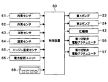
- the control device 60 is composed of a well-known microcomputer including a CPU, ROM, RAM, etc. and its peripheral circuits, and performs various calculations and processing based on an air conditioning control program stored in the ROM, and is connected to the output side.
- the control unit controls the operation of the first pump 23, the second pump 24, the compressor 42, the electric actuator 56 of the first switching valve 21, the electric actuator 57 of the second switching valve 22, and the like.
- the control device 60 is configured such that a control unit that controls various devices to be controlled connected to the output side thereof is integrally configured.
- the control device 60 controls the operation of each device to be controlled (that is, hardware and software). ) Constitutes a control unit that controls the operation of each control target device.
- Detection signals from the inside air sensor 61, the outside air sensor 62, the solar radiation sensor 63, the humidity sensor 64, the engine water temperature sensor 65, the battery monitoring unit 66, and the like are input to the input side of the control device 60.
- the inside air sensor 61 is an inside air temperature detecting unit that detects the inside air temperature of the passenger compartment.
- the outside air sensor 62 is an outside air temperature detecting unit that detects the outside air temperature of the passenger compartment.
- the solar radiation sensor 63 is a solar radiation amount detector that detects the amount of solar radiation in the passenger compartment.
- the humidity sensor 64 is a humidity detection unit that detects the humidity in the vehicle interior.
- the engine temperature sensor 65 is an engine temperature detection unit that detects the temperature of engine coolant.
- the battery monitoring unit 66 is a battery temperature detection unit that detects temperatures of a plurality of parts in the battery 40. More specifically, the battery monitoring unit 66 detects the temperature or the like of each cell constituting the battery 40.
- Operation signals from various air conditioning operation switches provided on the operation panel 68 disposed in the vicinity of the instrument panel in the front of the passenger compartment are input to the input side of the control device 60.
- various air conditioning operation switches provided on the operation panel 68 an air conditioner switch, an auto switch, an air volume setting switch, a vehicle interior temperature setting switch, and the like are provided.
- the air conditioner switch is a switch for switching on / off of air conditioning (that is, cooling or heating).
- the auto switch is a switch for setting or canceling automatic control of air conditioning.
- the air volume setting switch is a switch for setting the air volume of the indoor fan.
- the vehicle interior temperature setting switch is a target temperature setting unit that sets the vehicle interior target temperature by the operation of the passenger.
- the cooling water is an ethylene glycol aqueous solution containing ethylene glycol as the first solute.
- Ethylene glycol is used as a freezing point depressant.
- the cooling water contains polyphenols as the second solute.
- Polyphenols are substances that can be dissolved in an aqueous ethylene glycol solution. Polyphenols have greater solubility in ethylene glycol than in water. The content of polyphenols in the cooling water is smaller than both the amount of water and the amount of ethylene glycol.
- oligonol is used as polyphenols.
- Oligonol is a polyphenol oligomer obtained by reducing the molecular weight of a high molecular weight polyphenol polymer. The polyphenol polymer is insoluble in the ethylene glycol aqueous solution, but the oligonol obtained by lowering the molecular weight is soluble in the ethylene glycol aqueous solution.
- Oligonol includes one or more of catechin monomers, dimers, trimers, tetramers, pentamers, hexamers, heptamers, and octamers.
- the cooling water contains ethylene glycol in the range of 25-30%.
- the oligonol used as the second solute has a higher solubility in ethylene glycol than in water. That is, the higher the ethylene glycol concentration in the cooling water, the greater the solubility of oligonol. For this reason, in order to ensure the solubility of oligonol, it is desirable that the ethylene glycol concentration in the cooling water is 25% or more.
- the cooling water contains oligonol within a range of 0.5 to 1%.
- the oligonol concentration in the cooling water is less than 0.5%, the effect of lowering the freezing point is low. For this reason, in order to ensure the antifreezing function of the cooling water, it is desirable that the oligonol concentration in the cooling water is 0.5% or more.
- the concentration of oligonol in the cooling water is greater than 1%, it is difficult for the oligonol to dissolve in the cooling water, and a part of the oligonol may exist as a solid. In such a case, the cooling water is easily solidified starting from the solid oligonol, and the effect of lowering the freezing point is reduced. For this reason, in order to dissolve oligonol reliably in cooling water, it is desirable that the concentration of oligonol in cooling water be 1% or less.
- the freezing point of the cooling water is -35 ° C.
- the freezing point is ⁇ 35 ° C. when the ethylene glycol concentration is 50%, and the freezing point is ⁇ 15 ° C. when the ethylene glycol concentration is 25%.
- the freezing point can be lowered from ⁇ 15 ° C. to ⁇ 35 ° C. by including oligonol in the cooling water. That is, if the ethylene glycol concentration in the cooling water is the same, the freezing point can be significantly lowered by including oligonol in the cooling water.
- the ethylene glycol concentration can be reduced from 50% to 25% by including oligonol in the cooling water. That is, if the required freezing point is the same, the ethylene glycol concentration can be significantly reduced by incorporating oligonol in the cooling water.
- the first switching valve 21 described above has a structure capable of switching the communication state between the inflow / outflow ports 21a to 21f to three types.
- the second switching valve 22 is also configured to be able to switch the communication state between the inflow / outlet ports 22a to 22f to three types.
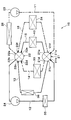
- FIG. 3 shows the operation of the cooling system 10 (that is, the first mode) when the first switching valve 21 and the second switching valve 22 are switched to the first state.
- the first switching valve 21 communicates the inflow / outflow port 21a with the inflow / outflow ports 21d, 21e, 21f, and communicates the inflow / outflow port 21b with the inflow / outflow port 21c.
- the first switching valve 21 causes the cooling water flowing in from the inflow / outflow port 21a to flow out from the inflow / outflow ports 21d, 21e, and 21f as shown by a one-dot chain line arrow in FIG. 3, and flows in as shown by the solid line arrow in FIG.
- the cooling water that has flowed in from the outlet 21b is caused to flow out of the inlet / outlet 21c.
- the second switching valve 22 communicates the inflow / outflow ports 22d, 22e, and 22f with the inflow / outflow port 22a and the inflow / outflow port 22c with the inflow / outflow port 22b.
- the second switching valve 22 causes the cooling water flowing in from the inflow / outflow ports 22d, 22e, and 22f to flow out of the inflow / outflow port 22a as shown by the one-dot chain line arrows in FIG. 3, and flows in as shown by the solid line arrows in FIG. Cooling water that has flowed in from the outlet 22c is caused to flow out of the inlet / outlet 22b.
- FIG. 4 shows the operation of the cooling system 10 (that is, the second mode) when the first switching valve 21 and the second switching valve 22 are switched to the second state.
- the first switching valve 21 communicates the inflow / outflow port 21a with the inflow / outflow ports 21d and 21f, and communicates the inflow / outlet port 21b with the inflow / outflow ports 21c and 21e.
- the first switching valve 21 causes the cooling water flowing in from the inflow / outflow port 21a to flow out from the inflow / outflow ports 21d and 21f as indicated by the one-dot chain line arrow in FIG. 4, and as illustrated in the solid line arrow in FIG.
- the cooling water that has flowed in from the outlets 21c and 21e is caused to flow out.
- the second switching valve 22 communicates the inflow / outflow ports 22c and 22e with the inflow / outflow port 22b and communicates the inflow / outflow ports 22d and 22f with the inflow / outflow port 22a.
- the second switching valve 22 causes the cooling water flowing in from the inflow / outflow ports 22d and 22f to flow out from the inflow / outflow port 22a as shown by the one-dot chain line arrow in FIG. , 22e is allowed to flow out from the inlet / outlet port 22b.
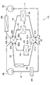
- FIG. 5 shows the operation of the cooling system 10 (that is, the third mode) when the first switching valve 21 and the second switching valve 22 are switched to the third state.
- the first switching valve 21 causes the inflow / outflow port 21a to communicate with the inflow / outflow port 21d, and allows the inflow / outflow port 21b to communicate with the inflow / outflow ports 21c, 21e, and 21f.
- the first switching valve 21 causes the cooling water flowing in from the inflow / outflow port 21a to flow out from the inflow / outflow port 21d as shown by a one-dot chain line arrow in FIG. The cooled water is discharged from the inflow / outflow ports 21c, 21e, and 21f.
- the second switching valve 22 causes the inflow / outlet port 22d to communicate with the inflow / outlet port 22a, and allows the inflow / outlet ports 22c, 22e, and 22f to communicate with the inflow / outlet port 22b.
- the second switching valve 22 causes the cooling water flowing in from the inflow / outflow port 22d to flow out from the inflow / outflow port 22a as shown by a one-dot chain line arrow in FIG. 5, and as shown by the solid line arrows in FIG. , 22f is allowed to flow out from the inlet / outlet port 22b.
- the control device 60 performs the first mode shown in FIG. 3, and the outside air temperature detected by the outside air sensor 62 exceeds 15 ° C. to 40 ° C.
- the second mode shown in FIG. 4 is performed.
- the third mode shown in FIG. 5 is executed.
- the control device 60 switches the first switching valve 21 and the second switching valve 22 to the first state shown in FIG. 3 and operates the first pump 23, the second pump 24, and the compressor 42.
- the first pump 23, the battery 40, the inverter 34, the EGR cooler 33, and the radiator 26 constitute a first cooling water circuit (medium temperature cooling water circuit), and the second pump 24, the chiller 35, and the cooler core 36 perform the second cooling.
- a water circuit low-temperature cooling water circuit
- the first cooling water circuit corresponds to the first heat transport circuit of the present disclosure
- the second cooling water circuit corresponds to the second heat transport circuit of the present disclosure.
- the cooling water discharged from the first pump 23 branches to the battery 40, the inverter 34 and the EGR cooler 33 by the first switching valve 21, and the battery 40, the inverter 34 and the EGR cooler are branched.
- the cooling water that has flowed through 33 in parallel is collected by the second switching valve 22, flows through the radiator 26, and is sucked into the first pump 23.
- the cooling water discharged from the second pump 24 flows through the chiller 35, through the first switching valve 21, through the cooler core 36, and through the second switching valve 22 to the second pump 24. Inhaled.
- the medium temperature cooling water cooled by the radiator 26 flows through the battery 40, the inverter 34 and the EGR cooler 33, and the low temperature cooling water cooled by the chiller 35 flows through the cooler core 36.
- the battery, inverter and exhaust gas are cooled by the medium temperature cooling water, and the blown air into the vehicle interior is cooled by the low temperature cooling water.
- the medium temperature cooling water cooled by the outside air by the radiator 26 becomes about 25 ° C., so that the battery 40, the inverter 34 and the exhaust gas can be sufficiently cooled by the medium temperature cooling water.
- the low-temperature cooling water cooled by the low-pressure refrigerant of the refrigeration cycle 41 at the chiller 35 is about 0 ° C., the air blown into the vehicle interior can be sufficiently cooled by the low-temperature cooling water.
- the battery 40, the inverter 34, and the exhaust gas are cooled by outside air, so that energy saving can be achieved as compared with the case where the battery 40, the inverter 34, and the exhaust gas are cooled by the low-pressure refrigerant of the refrigeration cycle 41.
- control device 60 switches the first switching valve 21 and the second switching valve 22 to the second state shown in FIG. 4 and operates the first pump 23, the second pump 24, and the compressor 42.
- the first pump 23, the inverter 34, the EGR cooler 33, and the radiator 26 constitute a first cooling water circuit (medium temperature cooling water circuit), and the second pump 24, the chiller 35, the cooler core 36, and the battery 40 perform the second cooling.
- a water circuit low-temperature cooling water circuit is configured.
- the cooling water discharged from the first pump 23 is branched to the inverter 34 and the EGR cooler 33 by the first switching valve 21, and flows through the inverter 34 and the EGR cooler 33 in parallel.
- the cooling water gathers at the second switching valve 22, flows through the radiator 26, and is sucked into the first pump 23.
- the cooling water discharged from the second pump 24 flows through the chiller 35 and is branched to the cooler core 36 and the battery 40 by the first switching valve 21, and the cooler core 36 and the battery 40 are connected in parallel.
- the flowing cooling water is collected by the second switching valve 22 and sucked into the second pump 24.
- the medium-temperature cooling water cooled by the radiator 26 flows through the inverter 34 and the EGR cooler 33, and the low-temperature cooling water cooled by the chiller 35 flows through the cooler core 36 and the battery 40.
- the inverter 34 and the exhaust gas are cooled by the medium-temperature cooling water, and the blown air and the battery 40 into the vehicle compartment are cooled by the low-temperature cooling water.
- the medium temperature cooling water cooled by the outside air by the radiator 26 becomes about 40 ° C., so that the inverter 34 and the exhaust gas can be sufficiently cooled by the medium temperature cooling water.
- the air blown into the vehicle compartment and the battery 40 can be sufficiently cooled by the low-temperature cooling water.
- the battery 40 since the battery 40 is cooled by the low-pressure refrigerant of the refrigeration cycle 41, the battery can be sufficiently cooled even when the outside air cannot sufficiently cool the battery due to the high outside air temperature. it can.
- the control device 60 switches the first switching valve 21 and the second switching valve 22 to the third state shown in FIG. 5 and operates the first pump 23, the second pump 24, and the compressor 42.
- a first cooling water circuit (medium temperature cooling water circuit) is configured by the first pump 23, the EGR cooler 33, and the radiator 26, and the second cooling is performed by the second pump 24, the chiller 35, the cooler core 36, the battery 40, and the inverter 34.
- a water circuit (low-temperature cooling water circuit) is configured.
- the cooling water discharged from the first pump 23 flows through the EGR cooler 33 through the first switching valve 21 and flows through the radiator 26 through the second switching valve 22. It is sucked into the pump 23.
- the cooling water discharged from the second pump 24 flows through the chiller 35, and is branched to the cooler core 36, the battery 40 and the inverter 34 by the first switching valve 21.
- the cooling water flowing in parallel through the inverter 34 is collected by the second switching valve 22 and sucked into the second pump 24.
- the medium-temperature cooling water cooled by the radiator 26 flows through the EGR cooler 33, and the low-temperature cooling water cooled by the chiller 35 flows through the cooler core 36, the battery 40, and the inverter 34.
- the exhaust gas is cooled by the cooling water cooled by the radiator 26, and the air blown into the vehicle compartment, the battery 40 and the inverter 34 are cooled by the cooling water cooled by the chiller 35.
- the medium temperature cooling water cooled by the outside air by the radiator 26 becomes about 50 ° C., so that the exhaust gas can be sufficiently cooled by the medium temperature cooling water.
- the air blown into the vehicle compartment, the battery 40 and the inverter 34 can be sufficiently cooled by the low-temperature cooling water.
- the battery 40 and the inverter 34 are cooled by the low-pressure refrigerant of the refrigeration cycle 41, the battery 40 and the inverter 34 cannot be sufficiently cooled by outside air because the outside air temperature is very high. Also, the battery 40 and the inverter 34 can be sufficiently cooled.
- the freezing point can be greatly lowered even when the ethylene glycol concentration is the same by adding a trace amount of oligonol as a polyphenol to the cooling water containing ethylene glycol. Moreover, in order to obtain the same freezing point, the ethylene glycol concentration can be greatly reduced by including oligonol in the cooling water.
- the proportion of water in the cooling water can be increased as the ethylene glycol concentration is reduced, the thermal properties of the cooling water can be improved and the viscosity can be lowered. Moreover, since the amount of oligonol contained in the cooling water is very small, it is possible to suppress adverse effects on the thermal properties of the cooling water as much as possible. As a result, it is possible to suppress an increase in the size of the flow paths 11 to 16, the pumps 23 and 24, the radiator 26, and the like.
- a plurality of heat exchange target devices 33, 34, 36, a plurality of heat exchangers 26, 35, and a plurality of pumps 23, 24 are arranged in the plurality of flow paths 11-16.
- a plurality of independent heat transport circuits can be formed by the switching valves 21 and 22.
- ethylene glycol is used as the first solute.
- a freezing point depressant other than ethylene glycol may be used as the first solute.
- propylene glycol, ethanol, methanol, or the like can be used as the first solute.
- catechins are used as the second solute, but not limited thereto, polyphenols other than catechins may be used.
- heat exchange target devices Various devices can be used as heat exchange target devices.
- a heat exchanger that is built in a seat on which an occupant is seated and that cools and heats the seat with cooling water may be used as the heat exchange target device.
- the number of heat exchange target devices may be any number as long as it is plural (two or more).
- the condenser 37 is disposed in the flow path through which the cooling water flows, and the cooling water is heated by exchanging heat between the cooling water and the high-pressure refrigerant (high-temperature refrigerant) of the refrigeration cycle 41. Also good.
- the condenser 37 corresponds to the heat exchanger of the present disclosure.
- the heat transport system of the present disclosure is applied to a hybrid vehicle.
- an electric vehicle that does not include an engine and obtains a driving force for vehicle traveling from a traveling electric motor, or a fuel cell is used as a traveling energy.
- the present disclosure may be applied to a fuel cell vehicle or the like serving as a generation unit.
Landscapes
- Engineering & Computer Science (AREA)
- Chemical & Material Sciences (AREA)
- Combustion & Propulsion (AREA)
- Physics & Mathematics (AREA)
- Thermal Sciences (AREA)
- Mechanical Engineering (AREA)
- Materials Engineering (AREA)
- Organic Chemistry (AREA)
- General Engineering & Computer Science (AREA)
- Chemical Kinetics & Catalysis (AREA)
- Air-Conditioning For Vehicles (AREA)
Applications Claiming Priority (2)
| Application Number | Priority Date | Filing Date | Title |
|---|---|---|---|
| JP2016026153A JP2017145973A (ja) | 2016-02-15 | 2016-02-15 | 熱輸送システム |
| JP2016-026153 | 2016-02-15 |
Publications (1)
| Publication Number | Publication Date |
|---|---|
| WO2017141590A1 true WO2017141590A1 (ja) | 2017-08-24 |
Family
ID=59625789
Family Applications (1)
| Application Number | Title | Priority Date | Filing Date |
|---|---|---|---|
| PCT/JP2017/000936 Ceased WO2017141590A1 (ja) | 2016-02-15 | 2017-01-13 | 熱輸送システム |
Country Status (2)
| Country | Link |
|---|---|
| JP (1) | JP2017145973A (https=) |
| WO (1) | WO2017141590A1 (https=) |
Cited By (1)
| Publication number | Priority date | Publication date | Assignee | Title |
|---|---|---|---|---|
| CN113748504A (zh) * | 2019-03-26 | 2021-12-03 | 株式会社电装 | 热输送介质及使用了该热输送介质的热输送系统 |
Citations (2)
| Publication number | Priority date | Publication date | Assignee | Title |
|---|---|---|---|---|
| JP2014020280A (ja) * | 2012-07-18 | 2014-02-03 | Denso Corp | 車両用熱管理システム |
| JP2015212376A (ja) * | 2010-03-04 | 2015-11-26 | 国立大学法人北海道大学 | タンニンを含有する不凍性液体及びガラス化液 |
-
2016
- 2016-02-15 JP JP2016026153A patent/JP2017145973A/ja active Pending
-
2017
- 2017-01-13 WO PCT/JP2017/000936 patent/WO2017141590A1/ja not_active Ceased
Patent Citations (2)
| Publication number | Priority date | Publication date | Assignee | Title |
|---|---|---|---|---|
| JP2015212376A (ja) * | 2010-03-04 | 2015-11-26 | 国立大学法人北海道大学 | タンニンを含有する不凍性液体及びガラス化液 |
| JP2014020280A (ja) * | 2012-07-18 | 2014-02-03 | Denso Corp | 車両用熱管理システム |
Cited By (1)
| Publication number | Priority date | Publication date | Assignee | Title |
|---|---|---|---|---|
| CN113748504A (zh) * | 2019-03-26 | 2021-12-03 | 株式会社电装 | 热输送介质及使用了该热输送介质的热输送系统 |
Also Published As
| Publication number | Publication date |
|---|---|
| JP2017145973A (ja) | 2017-08-24 |
Similar Documents
| Publication | Publication Date | Title |
|---|---|---|
| CN110549817B (zh) | 热流管理设备以及用于运行热流管理设备的方法 | |
| KR102382721B1 (ko) | 자동차의 통합 열관리 시스템 | |
| US12334530B2 (en) | Cooling water circuit | |
| US9643469B2 (en) | Vehicle thermal management system | |
| US20140202178A1 (en) | Multiple circuit cooling system | |
| US9016080B2 (en) | Battery heating and cooling system | |
| US11752833B2 (en) | System for air-conditioning the air of a passenger compartment and for heat transfer with drive components of a motor vehicle and method for operating the system | |
| CN104842752B (zh) | 车辆冷却回路 | |
| JP5187786B2 (ja) | 車両用ヒートポンプシステム | |
| KR101759027B1 (ko) | 자동차의 공기 조화 시스템 및 상기 공기 조화 시스템의 작동 방법 | |
| US10065478B2 (en) | Thermal management system for vehicle | |
| US8893522B2 (en) | Cooling device | |
| US9649908B2 (en) | Temperature regulation device | |
| US20120304674A1 (en) | Climate control system for a vehicle and method for controlling temperature | |
| US20170021698A1 (en) | Vehicle-mounted temperature adjustment device, vehicle air-conditioning device, and battery temperature adjustment device | |
| US20130025311A1 (en) | Motor vehicle refrigerant circuit with a refrigeration system circuit and a heat pump circuit | |
| JP6083304B2 (ja) | 車両用熱管理システム | |
| JPWO2011087001A1 (ja) | 車両用空調システム | |
| JP2010115993A (ja) | 車両用空調装置 | |
| US20150276281A1 (en) | Method for Operating a Refrigerant Circuit as a Heat Pump and Heat Pump Operable as a Refrigerant Circuit | |
| US12257882B2 (en) | Air conditioning device for vehicle | |
| JP5896817B2 (ja) | 冷却発電システム | |
| JP2014037179A (ja) | 電動車両用熱管理システム | |
| CN110402203A (zh) | 具有可作为用于ac运行的制冷循环回路工作和作为用于加热运行的热泵循环回路工作的制冷介质循环回路的车辆的制冷设备 | |
| WO2017141590A1 (ja) | 熱輸送システム |
Legal Events
| Date | Code | Title | Description |
|---|---|---|---|
| 121 | Ep: the epo has been informed by wipo that ep was designated in this application |
Ref document number: 17752854 Country of ref document: EP Kind code of ref document: A1 |
|
| NENP | Non-entry into the national phase |
Ref country code: DE |
|
| 122 | Ep: pct application non-entry in european phase |
Ref document number: 17752854 Country of ref document: EP Kind code of ref document: A1 |