WO2017141583A1 - モータ駆動装置 - Google Patents
モータ駆動装置 Download PDFInfo
- Publication number
- WO2017141583A1 WO2017141583A1 PCT/JP2017/000723 JP2017000723W WO2017141583A1 WO 2017141583 A1 WO2017141583 A1 WO 2017141583A1 JP 2017000723 W JP2017000723 W JP 2017000723W WO 2017141583 A1 WO2017141583 A1 WO 2017141583A1
- Authority
- WO
- WIPO (PCT)
- Prior art keywords
- motor
- rotor
- sensor
- external magnetic
- magnetic sensor
- Prior art date
Links
Images


Classifications
-
- H—ELECTRICITY
- H02—GENERATION; CONVERSION OR DISTRIBUTION OF ELECTRIC POWER
- H02K—DYNAMO-ELECTRIC MACHINES
- H02K29/00—Motors or generators having non-mechanical commutating devices, e.g. discharge tubes or semiconductor devices
- H02K29/06—Motors or generators having non-mechanical commutating devices, e.g. discharge tubes or semiconductor devices with position sensing devices
- H02K29/08—Motors or generators having non-mechanical commutating devices, e.g. discharge tubes or semiconductor devices with position sensing devices using magnetic effect devices, e.g. Hall-plates, magneto-resistors
-
- H—ELECTRICITY
- H02—GENERATION; CONVERSION OR DISTRIBUTION OF ELECTRIC POWER
- H02K—DYNAMO-ELECTRIC MACHINES
- H02K11/00—Structural association of dynamo-electric machines with electric components or with devices for shielding, monitoring or protection
- H02K11/20—Structural association of dynamo-electric machines with electric components or with devices for shielding, monitoring or protection for measuring, monitoring, testing, protecting or switching
- H02K11/21—Devices for sensing speed or position, or actuated thereby
- H02K11/215—Magnetic effect devices, e.g. Hall-effect or magneto-resistive elements
-
- H—ELECTRICITY
- H02—GENERATION; CONVERSION OR DISTRIBUTION OF ELECTRIC POWER
- H02P—CONTROL OR REGULATION OF ELECTRIC MOTORS, ELECTRIC GENERATORS OR DYNAMO-ELECTRIC CONVERTERS; CONTROLLING TRANSFORMERS, REACTORS OR CHOKE COILS
- H02P6/00—Arrangements for controlling synchronous motors or other dynamo-electric motors using electronic commutation dependent on the rotor position; Electronic commutators therefor
- H02P6/14—Electronic commutators
- H02P6/16—Circuit arrangements for detecting position
-
- H—ELECTRICITY
- H02—GENERATION; CONVERSION OR DISTRIBUTION OF ELECTRIC POWER
- H02K—DYNAMO-ELECTRIC MACHINES
- H02K11/00—Structural association of dynamo-electric machines with electric components or with devices for shielding, monitoring or protection
- H02K11/20—Structural association of dynamo-electric machines with electric components or with devices for shielding, monitoring or protection for measuring, monitoring, testing, protecting or switching
- H02K11/27—Devices for sensing current, or actuated thereby
-
- H—ELECTRICITY
- H02—GENERATION; CONVERSION OR DISTRIBUTION OF ELECTRIC POWER
- H02K—DYNAMO-ELECTRIC MACHINES
- H02K11/00—Structural association of dynamo-electric machines with electric components or with devices for shielding, monitoring or protection
- H02K11/30—Structural association with control circuits or drive circuits
- H02K11/33—Drive circuits, e.g. power electronics
Definitions
- the present invention relates to a motor drive device, and more particularly to a motor drive device for an outer rotor type sensorless brushless motor.
- the commutator motor has a structure in which a coil is used for the rotor and a permanent magnet is used for the stator, and the rotor is rotated by controlling the commutation timing of each coil of the rotor with a mechanical switch using a commutator and a brush. It is.
- a brushless motor has a structure in which a permanent magnet is used for a rotor and a coil is used for a stator, and the rotor is rotated by electronically controlling the commutation timing of each coil of the stator with an inverter circuit.
- the inverter circuit plays the role of the brush and commutator of the commutator motor, so there is no electrical noise or mechanical noise caused by the mechanical contact between the brush and commutator. In addition, it is characterized by excellent quietness.
- a brushless motor with a sensor has a plurality of magnetic sensors such as Hall ICs arranged inside the motor, and the position angle and rotation angle of the rotor, the rotation speed (number of rotations), the rotation direction (hereinafter referred to as these) This is a brushless motor of a type that generally detects “position angle and the like”.
- a sensorless brushless motor is a brushless motor of a type that detects the position angle of a rotor without using a magnetic sensor, and generally uses a back electromotive force of a coil.
- the advantages of a brushless motor with a sensor are that it is possible to specify the position angle of the rotor including when the rotor is stopped with high accuracy, and the step of calculating the position angle of the rotor from the back electromotive force is unnecessary.
- the quick response of the motor, the high torque can be maintained even at the low speed rotation, the high power saving performance and the like.
- the disadvantage is that the Hall IC, which is generally used as a magnetic sensor, has a temperature limit, so it cannot be used in a high temperature environment, and the number of wires connecting the motor and the drive circuit is large, resulting in complicated cabling.
- the cost is higher than that of a sensorless brushless motor.
- sensorless brushless motors are that they can be used in high-temperature environments because they do not require a magnetic sensor, the number of wires is simple and cabling is simple, and the cost is lower than that of brushless motors with sensors. That can be done. Disadvantages are that there is a time constant in the back electromotive force detection circuit, there is a limit to the rotation speed that can be used, it is not suitable for operations that repeatedly accelerate and decelerate, and the back electromotive force depends on the rotation of the rotor. Therefore, the control is complicated such as correcting the rotation direction after starting.
- sensorless brushless motors and sensorless brushless motors have their merits and demerits, and are used differently according to their use and allowable cost.
- a device using a sensorless brushless motor may be preferable to use a sensorless brushless motor depending on the purpose.
- the problem to be solved by the present invention is to provide a motor drive device capable of imparting the characteristics of a brushless motor with a sensor to an outer rotor type sensorless brushless motor.
- a motor driving device of the present invention is a motor driving device for an outer rotor type sensorless brushless motor (hereinafter also simply referred to as “motor”), and the motor driving device includes an external magnetic device.
- a sensor and a drive circuit unit, and the external magnetic sensor is capable of detecting a leakage magnetic flux of a permanent magnet disposed on an inner peripheral surface of the rotor of the motor from the outside of the rotor.
- the motor is driven based on a control signal of the motor input to the drive circuit unit and feedback of the external magnetic sensor.
- a plurality of permanent magnets are arranged on the inner peripheral surface of the motor case, and the motor case itself rotates as a rotor.
- the plurality of permanent magnets are arranged along the circumferential direction of the inner peripheral surface of the motor case so that the directions of the magnetic poles are opposite to each other with the adjacent permanent magnets.
- the magnetic flux of each of these permanent magnets leaks out to the outside of the motor case, though a little.
- the external magnetic sensor is a sensor using a Hall element, and it is preferable that the Hall voltage generated by the magnetic field of the leakage magnetic flux is fed back as an analog signal to the drive circuit unit.
- sensorless brushless motors often use Hall ICs as their magnetic sensors. This is because the arrangement position of the Hall IC in the motor is optimized, and the position angle of the rotor and the like can be specified easily and with high accuracy by determining with a digital value.
- a Hall element is used as the magnetic sensor, and the Hall voltage is expressed as an analog signal, so that the position angle of the rotor can be specified from the slight strength of the leakage flux. It is also possible to substitute the Hall element with a plurality of Hall ICs. In this case, since it is necessary to set the arrangement interval of each Hall IC strictly, it is necessary to adjust the arrangement interval for each motor. Equivalent functions can be realized.
- a plurality of the external magnetic sensors are arranged along the circumferential direction of the rotor.
- Detecting the leakage magnetic flux not only from one point in the circumferential direction of the rotor but also from a plurality of points makes it possible to specify the position angle of the rotor even when the rotor is stopped. Further, since the arrangement of the magnetic poles of the permanent magnet when the rotor is stopped can be specified, the rotor can be rotated in an arbitrary direction when the motor is started. Thereby, a smooth starting operation of the motor can be realized.
- a plurality of the external magnetic sensors are arranged along the circumferential direction of the rotor, and the arrangement interval of these external magnetic sensors is the width of each permanent magnet arranged on the inner circumferential surface of the rotor in the rotation direction. Narrower or wider than that is preferred.
- the rotor position angle can be specified to some extent.
- the drive circuit unit is capable of adjusting the advance angle of the motor according to the rotation speed of the motor so that the torque at that time becomes maximum.
- the external magnetic sensor has two magnetic sensors, that is, a main sensor and a sub sensor arranged side by side in a direction parallel to the axial direction of the rotor as a unit.
- the average value can be taken to increase the detection accuracy of the position angle, etc. It becomes possible to improve the reliability by making a spare when the main sensor fails.
- the sensor adapter unit attached to the motor is further provided, the external magnetic sensor is fixed to the sensor adapter unit, and the external magnetic sensor is the sensor adapter unit of the sensor adapter unit. It is good also as a structure arrange
- the sensor adapter part has a bottom part coupled to the bottom surface of the motor, and a side part disposed on the side of the motor, and the side part extends vertically from the top surface of the bottom part.
- the side portion is located within a range that covers at least a part of the rotor outer peripheral surface in the circumferential direction along the shape of the rotor outer peripheral surface of the motor, and a slight gap is provided between the side portion and the rotor outer peripheral surface.
- the external magnetic sensor may be arranged on the side portion of the sensor adapter unit.
- the position of the external magnetic sensor can be easily adjusted by separately providing a sensor adapter for arranging the external magnetic sensor near the rotor.
- the motor drive device of the present invention it is possible to give the characteristics of the brushless motor with a sensor to the outer rotor type sensorless brushless motor.
- the following embodiment is an example in which the motor drive device of the present invention is applied to an unmanned aerial vehicle including a plurality of rotor blades.
- the unmanned aerial vehicle of the present embodiment is a product on which an outer rotor type sensorless brushless motor is mounted, and the original motor driving device is replaced with the motor driving device of the present invention.
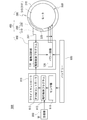
- FIG. 1 is a block diagram showing a functional configuration of the unmanned aerial vehicle 900.
- Main functions of the unmanned aerial vehicle 900 in the present embodiment are a flight controller 910, a motor driving device 400, and a motor 500, which will be described later, a receiver 950 that receives a steering signal from a pilot of the unmanned aircraft 900, and the unmanned aircraft.
- the battery 920 supplies power to each of the 900 devices.
- the functions of the flight controller 910 are mainly configured by sensors 911, a flight control program 912, and a PWM controller 913.
- the sensors 910 acquire the position information of the own aircraft including the current latitude and longitude, altitude, and azimuth angle of the nose, in addition to the tilt and rotation of the unmanned aircraft 900.
- the flight control program 912 is a program for controlling the attitude and basic flight operation of the unmanned aircraft 900 in flight while taking into account the output values of these sensors 910.
- the PWM controller 913 is a device that converts an instruction of the flight control program 912 into a PWM signal (control signal) and transmits it to the motor driving device 400.
- FIG. 2 is a plan view sectional view of the motor 500.
- the motor 500 is a general outer rotor type sensorless brushless motor.
- the motor case 510 of the motor 500 has eight permanent magnets 520 disposed on the inner peripheral surface thereof, and the motor case 510 itself rotates as a rotor 510 ′.
- the “rotor” in the present invention means the motor case 510.
- These eight permanent magnets 520 are arranged along the circumferential direction of the inner peripheral surface of the motor case 510 so that the direction of the magnetic poles is opposite to that of the adjacent permanent magnet 520.
- the magnetic flux of each of these permanent magnets 520 leaks to the outside of the motor case 510 although it is slight because the motor case 510 acts as a yoke.
- the motor driving device 400 is a motor driving device dedicated to an outer rotor type sensorless brushless motor such as the motor 500 of the present embodiment. As shown in FIG. 1, the motor drive device 400 includes an external magnetic sensor 200 (external magnetic sensors 210 and 220), a drive circuit unit 100, and a sensor adapter unit 300.
- Instructions such as start / stop, rotation direction (CW / CCW), and rotation speed (number of rotations) for the motor 500 are created by the flight control program 912 of the flight controller 910.
- the instruction is converted into a PWM signal by the PWM controller 913 and input to the drive circuit unit 100 of the motor drive device 400.
- the drive circuit unit 100 is connected to each coil 531 (see FIG. 2) of the motor 500 by lead wires u, v, w, and leads according to the PWM signal received from the PWM controller 913 (instruction of the flight control program 912).
- the motor 500 is driven by controlling the currents u, v, and w.
- the external magnetic sensor 200 is a magnetic sensor using a Hall element.
- the external magnetic sensor 200 is fixed to the sensor adapter unit 300, and detects the leakage magnetic flux of the rotor 510 'near the side of the rotor 510'.
- the wiring 201 of the external magnetic sensor 200 is connected to the drive circuit unit 100, and the external magnetic sensor 200 feeds back the Hall voltage generated by the magnetic field of the leakage magnetic flux to the drive circuit unit 100 as an analog signal (hereinafter referred to as this).
- Such a magnetic sensor is also referred to as an “analog magnetic sensor”).
- a Hall IC is often used as the magnetic sensor, but in this embodiment, the Hall voltage value is intentionally fed back as an analog signal, so that the rotor 510 ′ It is possible to specify the position angle and the like.
- the analog magnetic sensor using the Hall element naturally includes a linear Hall IC.
- the external magnetic sensor 200 does not always need to be an analog magnetic sensor. Depending on the required detection accuracy, the number and positions of the external magnetic sensors 200 to be arranged, a general Hall IC (H or L (A magnetic sensor that outputs a digital value) can also be used.
- H or L A magnetic sensor that outputs a digital value
- Two external magnetic sensors 200 in the present embodiment are arranged along the circumferential direction of the rotor 510 ′ (external magnetic sensors 210, 220).
- the interval between the two external magnetic sensors 210 and 220 is narrower than the width in the rotation direction of each permanent magnet 520 of the rotor 510 ′ (hereinafter also simply referred to as “the width of the permanent magnet 520”).
- the width of the permanent magnet 520 it is possible to specify the rough position angle of the rotor 510 ′ with a simple determination as to whether the external magnetic sensors 210 and 220 indicate the same magnetic pole or different magnetic poles. Compared with the case where there is only one magnetic sensor 200, the detection accuracy of the position angle when the rotor 510 ′ is stopped is improved.
- Table 1 shown in the next paragraph is a graph modeling leakage magnetic flux (Hall voltage value) detected by the external magnetic sensors 210 and 220.
- the solid line waveform is the Hall voltage value of the external magnetic sensor 210
- the broken line waveform is the Hall voltage value of the external magnetic sensor 220.
- the waveform shown in Table 1 is a state when the rotor 510 ′ is rotated once in the clockwise direction (CW).
- the positive-side extreme value A corresponds to the center of the N-pole permanent magnet 520 in the width direction
- the negative-side extreme value B corresponds to the center of the S-pole permanent magnet 520 in the width direction.
- the magnetic forces of the stator 530 and the permanent magnet 520 inside the motor 500 interfere with each other and the waveform is not as beautiful as shown in Table 1. This is not a problem in actual operation.
- the number of external magnetic sensors 200 is not always two, and may be one or three or more depending on the necessity of a smooth start operation and the required reliability. For example, when three external magnetic sensors 200 are arranged in the circumferential direction, even if one of them fails, the detection performance such as the position angle is not affected. In this manner, the external magnetic sensor 200 can be provided with dependability.
- the two or more external magnetic sensors 200 exert the effect of the number mainly when the position angle of the stopped rotor 510 ′ is specified. After the rotor 510 ′ starts rotating, basically only the rotational speed (the number of rotations) is monitored. Therefore, even if one or more external magnetic sensors 200 are used, the effect is not so different.
- the interval between the external magnetic sensors 200 need not always be narrower than the width of each permanent magnet 520, and conversely, the interval may be wider than the width of each permanent magnet 520.
- the arrangement interval is a multiple of 45 ° (360 ° / 8)
- these external magnetic sensors 200 always detect the same or opposite magnetic poles.
- the meaning of arranging a plurality of external magnetic sensors 200 becomes sparse. Therefore, it is desirable that the arrangement interval of the external magnetic sensor 200 be an interval other than a multiple of at least 360 ° / (the number of permanent magnets 520).
- “specification of position angle” does not specify the absolute position (position angle in the range of 360 °) of the rotor 510 ′ but 360 ° / (number of permanent magnets 520) ⁇ 2 (adjacent).
- N pole and S pole that is, in the present embodiment, it means specifying a position angle within a range of 90 ° out of a range of 360 °.
- Table 1 the combination of the values of the external magnetic sensors 210 and 220 is unique regardless of which angle is cut out within an arbitrary 90 ° range.
- the absolute angle of the rotor 510 ′ is not known, but the magnetic pole arrangement of the permanent magnet 520 of the rotor 510 ′ at that time can be specified.
- the rotor 510 ′ can be rotated in an arbitrary direction from the beginning. ing. That is, a smooth starting operation is realized.
- FIG. 3 is a perspective view and a front view showing the external appearance of the sensor adapter unit 300.
- the external magnetic sensors 210 and 220 are arranged in a direction parallel to the axial direction of the rotor 510 ′ (vertically arranged in FIG. 3B).
- Two magnetic sensors 211 and 221 and sub-sensors 212 and 222 are configured as a unit.
- only the main sensors 211 and 221 are basically used as the external magnetic sensors 210 and 220.
- there is an abnormality in the operation of the main sensors 211 and 221 such as the feedback from the main sensors 211 and 221 being interrupted.
- Sub-sensors 212 and 222 are used only when they occur.
- the proper use of the main sensors 211 and 221 and the sub sensors 212 and 222 is not limited to the mode of the present embodiment.
- an average value is obtained for each of the main sensors 211 and 221 and the sub sensors 212 and 222, or the main sensors 211 and 221 are used. It is also possible to employ only one of the sub sensors 212 and 222 having a clear Hall voltage value waveform.
- the drive circuit unit 100 is a microcontroller that controls the rotation of the motor 500 based on the PWM signal of the PWM controller 913 and the feedback of the external magnetic sensor 200.
- the basic function of the drive circuit unit 100 is the same as that of a sensorless brushless motor drive circuit (sometimes referred to as “ESC (Electric Speed Controller)” or “amplifier”).
- ESC Electronic Speed Controller
- the drive circuit unit 100 mainly includes a drive control program 110 and a power circuit 120.
- the power circuit 120 includes an inverter circuit composed of a transistor, and reverses the direction of the current flowing through the coil 531 of the stator 530 by switching the transistor on and off.
- the drive control program 110 specifies the position angle of the rotor 510 ′ from the feedback of the external magnetic sensor 200 according to the PWM signal from the PWM controller 913, operates the base of each transistor through the power circuit 120, and the coil 531. To control the commutation timing.
- the leakage magnetic flux detected by the external magnetic sensor 200 is fed back to the drive circuit unit 100, and the drive circuit unit 100 drives the motor 500 based on the feedback, so that the sensorless brushless motor is treated as if it were a brushless with a sensor. It can be controlled like a motor. That is, it is possible to give the advantages of the sensorless brushless motor to the sensorless brushless motor. That is, while using a sensorless brushless motor, the position angle of the rotor 510 ′ including when the rotor 510 ′ is stopped can be specified with high accuracy, the response of the motor 500 is improved, and high torque is maintained even at low speed rotation. This makes it possible to improve power saving.
- the drive control program 110 of the drive circuit unit 100 has a function of automatically adjusting the advance angle of the motor 500 according to the rotational speed of the motor 500 so that the torque at that time becomes maximum.
- a motor has a specific rotation speed as a peak, and the torque decreases even if the rotation speed increases or decreases.
- the drive control program 110 can maintain a high torque from a low speed to a high speed by automatically increasing or decreasing the advance angle according to the increase or decrease of the rotation speed of the motor 500. It is said that.
- the rotation speed within a predetermined time and the load according to the rotation speed are parameterized, and an equation for calculating the optimum advance angle according to the rotation speed at that time is used as a function to obtain any rotation speed.
- an equation for calculating the optimum advance angle according to the rotation speed at that time is used as a function to obtain any rotation speed.
- the parameter values are expected to be substantially the same.
- the sensor adapter unit 300 is a member for arranging and fixing the external magnetic sensor 200 at an optimal position for detecting leakage magnetic flux in the vicinity of the side of the rotor 510 ′.
- the sensor adapter unit 300 is a resin or metal member, and includes a disc-shaped bottom portion 310 screwed to the bottom surface of the motor 500, and a side portion extending vertically from the outer edge portion of the bottom portion 310 to the motor 500 side. 320.
- the side portion 320 is arranged along the shape of the outer peripheral surface of the rotor 510 ′ so as to cover a part in the circumferential direction with a slight gap provided between the side portion 320 and the outer peripheral surface of the rotor 510 ′.
- the external magnetic sensor 200 is disposed on the side portion 320. Thereby, when the sensor adapter part 300 is attached to the motor 500, the external magnetic sensor 200 is disposed at a position near the rotor 510 ′ side.
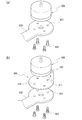
- FIG. 4 is a diagram illustrating an assembly process of the sensor adapter unit 300.
- FIG. 4A shows a state where the motor 500 is removed from the arm 930 of the unmanned aerial vehicle 900. When removing the motor 500 from the arm 930, it is only necessary to remove the set screw 932 connecting them.
- FIG. 4B shows how the sensor adapter unit 300 is attached to the motor 500 and the arm 930.
- a through hole 311 is provided in the bottom portion 310 of the sensor adapter unit 300 at the same position as the screw hole provided in the bottom surface of the motor 500.
- the bottom 310 of the sensor adapter unit 300 is sandwiched between the motor 500 and the arm 930, and a set screw 932 is attached to the motor 500 through the through hole 311 of the bottom 310.
- the motor drive device 400 of the present embodiment includes the sensor adapter unit 300, the position of the external magnetic sensor 200 can be easily adjusted and the external magnetic sensor 200 can be easily fixed at a position optimal for detecting leakage magnetic flux. It is possible to do.
- the sensor adapter unit 300 is not an indispensable configuration. For example, depending on the shape of the unmanned aircraft 900, it may be possible to directly fix the external magnetic sensor 200 to the body.
Abstract
アウターロータ型センサレスブラシレスモータに対して、センサ付きブラシレスモータの特性を付与可能なモータ駆動装置を提供する。 アウターロータ型センサレスブラシレスモータ(以下、単に「モータ」という。)用のモータ駆動装置であって、前記モータ駆動装置は、外付け磁気センサと駆動回路部とを有し、前記外付け磁気センサは、前記モータのロータ内周面に配置された永久磁石の漏れ磁束を前記モータの外部から検知可能であり、前記駆動回路部は、該駆動回路部に入力された前記モータの制御信号と、前記 外付け磁気センサのフィードバックとに基づいて前記モータの回転を制御することを特徴とするモータ駆動装置。により解決する。
Description
本発明はモータ駆動装置に関し、更に詳しくは、アウターロータ型センサレスブラシレスモータ用のモータ駆動装置に関する。
従来、整流子モータの構造的な欠点を改良したモータとしてブラシレスモータが広く使用されている。整流子モータは、ロータにコイルが、ステータに永久磁石が用いられた構造であり、ロータの各コイルの転流タイミングを整流子とブラシによる機械的なスイッチで制御することでロータを回転させるモータである。一方、ブラシレスモータは、ロータに永久磁石が、ステータにコイルが用いられた構造であり、ステータの各コイルの転流タイミングをインバータ回路で電子的に制御することでロータを回転させるモータである。ブラシレスモータでは、整流子モータのブラシと整流子の役割をインバータ回路が担っていることから、これらブラシと整流子の機械的接触に起因する電気ノイズや機械ノイズがなく、モータの寿命、メンテナンス性、および静音性に優れるという特徴がある。
ブラシレスモータには、センサ付きブラシレスモータと、センサレスブラシレスモータの二種類がある。センサ付きブラシレスモータとは、ホールICなどの磁気センサをモータ内部に複数配置し、これら磁気センサのフィードバックからロータの位置角度や回転角度、回転速度(回転数)、回転方向、(以下、これらを総称して「位置角度等」ともいう。)を検出する方式のブラシレスモータである。一方、センサレスブラシレスモータとは、磁気センサを用いることなくロータの位置角度等を検知する方式のブラシレスモータであり、コイルの逆起電力を利用したものが一般的である。
センサ付きブラシレスモータの長所としては、ロータ停止時を含むロータの位置角度等を高い精度で特定することができ、また、逆起電力からロータの位置角度等を算出するステップが不要であることから、モータのレスポンスが早いこと、低速回転時でも高いトルクを維持可能であること、高い省電力性などがあげられる。一方、短所としては、磁気センサとして一般に使用されるホールICに温度制限があるため高温環境下では使用できないことや、モータと駆動回路を接続する配線の本数が多く、ケーブリングが煩雑になること、センサレスブラシレスモータに比べて高コストになることなどがあげられる。
センサレスブラシレスモータの長所としては、磁気センサが不要であるため高温環境下でも使用可能であること、配線の数が少なくケーブリングが簡単であること、センサ付きブラシレスモータに比べてコストを低く抑えることができることなどがあげられる。短所としては、逆起電力の検出回路に時定数があり、使用できる回転速度に制限があることや、加減速を繰り返すような動作には適さないこと、さらに、逆起電力はロータの回転により発生するため、始動後に回転方向を修正するなど、制御が複雑になることなどがあげられる。
上で述べたように、センサ付きブラシレスモータとセンサレスブラシレスモータはそれぞれ一長一短があり、その用途や許容されるコストに応じて使い分けがされている。しかし、例えばセンサレスブラシレスモータが使われている機器であっても、目的によってはセンサ付きブラシレスモータを用いる方が望ましい場合がある。
一般に、センサレスブラシレスモータが予め組み付けられている機器で、そのモータをセンサ付きブラシレスモータに交換するためには、モータと駆動回路の両方を交換する必要があり、コスト的な無駄が大きい。さらにアウターロータ型モータなど、インナーロータ型よりも種類の少ないモータでは、代用可能なセンサ付きブラシレスモータが見つからず、交換自体が難しいことがある。更に、アウターロータ構造はモータ内部のスペースが狭く、モータ内に事後的にセンサを設置することも難しい。
上記問題に鑑み、本発明が解決しようとする課題は、アウターロータ型センサレスブラシレスモータに対して、センサ付きブラシレスモータの特性を付与可能なモータ駆動装置を提供することにある。
上記課題を解決するため、本発明のモータ駆動装置は、アウターロータ型センサレスブラシレスモータ(以下、単に「モータ」ともいう。)用のモータ駆動装置であって、前記モータ駆動装置は、外付け磁気センサと駆動回路部とを有し、前記外付け磁気センサは、前記モータのロータ内周面に配置された永久磁石の漏れ磁束を該ロータの外部から検知可能であり、前記駆動回路部は、該駆動回路部に入力された前記モータの制御信号と、前記外付け磁気センサのフィードバックとに基づいて前記モータを駆動することを特徴とする。
アウターロータ型モータは、モータケースの内周面に複数の永久磁石が配置されており、モータケース自体がロータとして回転する。これら複数の永久磁石は、モータケース内周面の周方向に沿って、隣接する永久磁石と互いに磁極の向きが反対となるように並べられている。これら各永久磁石の磁束は、僅かではあるがモータケースの外部にも漏出している。外付け磁気センサによりこの漏れ磁束を検知して、駆動回路部にフィードバックすることにより、センサレスブラシレスモータをあたかもセンサ付きブラシレスモータのように制御することが可能となる。
また、前記外付け磁気センサはホール素子を用いたセンサであり、前記漏れ磁束の磁場により発生したホール電圧をアナログ信号として前記駆動回路部にフィードバックすることが好ましい。
センサ付きブラシレスモータでは、一般に、その磁気センサとしてホールICが用いられることが多い。これは、モータ内部におけるホールICの配置位置が最適化されており、デジタル値で判定した方が簡便かつ高精度にロータの位置角度等を特定できるからである。本構成では、磁気センサとしてホール素子を用い、ホール電圧をあえてアナログ信号で表現することにより、漏れ磁束の僅かな強弱からロータの位置角度等を特定することが可能とされている。なお、ホール素子を複数のホールICで代用することも可能である。この場合、各ホールICの配置間隔を厳密に設定する必要があることから、モータごとにその配置間隔を調節する必要がある等、製造上の難点があるが、ホール素子を用いた場合とほぼ同等の機能を実現することができる。
また、前記外付け磁気センサは、前記ロータの周方向に沿って複数配置されていることが好ましい。
ロータの周方向における一点のみでなく、複数点から漏れ磁束を検知することにより、ロータの停止時においてもロータの位置角度を特定することが可能となる。さらに、ロータ停止時におけるその永久磁石の磁極配置が特定できることにより、モータ始動時にロータを任意の方向に回転させることが可能になる。これにより、モータの滑らかな始動動作を実現することができる。
また、前記外付け磁気センサは、前記ロータの周方向に沿って複数配置されており、これら外付け磁気センサの配置間隔は、前記ロータ内周面に配置された各永久磁石の回転方向における幅よりも狭いまたは広いことが好ましい。
永久磁石のその回転方向における幅とは異なる間隔で複数の外付け磁気センサが配置されていることにより、これら隣接する外付け磁気センサが同じ磁極を示すか、異なる磁極を示すかという簡単な判定でロータの位置角度をある程度特定することが可能となる。
また、前記駆動回路部は、前記モータの回転速度に応じて、そのときのトルクが最大となるように該モータの進角を調節可能であることが好ましい。
ロータの回転速度(回転数)に応じて動的に進角を最適化することにより、センサレスブラシレスモーターを用いつつも、低速回転時から高速回転時にわたって高いトルクを維持することが可能となる。
また、前記外付け磁気センサは、前記ロータの軸方向と平行する方向に並べて配置された主センサおよび副センサの二つの磁気センサを一単位とすることが好ましい。
ロータに対して縦(軸方向と平行する方向)に並べられた二つの磁気センサを一単位として扱うことにより、例えばその平均値をとって位置角度等の検知精度を高めることや、副センサを主センサ故障時の予備とすることで信頼性を向上させることが可能となる。
また、前記モータに取り付けられるセンサアダプタ部をさらに備え、前記外付け磁気センサは前記センサアダプタ部に固定されており、前記外付け磁気センサは、前記センサアダプタ部の部位のうち、前記センサアダプタ部が前記モータに取り付けられたときに、前記モータの側方近傍となる位置に配置されている構成としてもよい。
さらに、前記センサアダプタ部は、前記モータの底面に結合される底部と、前記モータの側方に配置される側部と、を有し、前記側部は前記底部の上面から垂直に延出しており、前記側部は、前記モータのロータ外周面の形状に沿って、該ロータ外周面の周方向における少なくとも一部を覆う範囲で、該ロータ外周面との間に僅かに隙間が設けられる位置に配置されており、前記外付け磁気センサは、前記センサアダプタ部の前記側部に配置されている構成としてもよい。
外付け磁気センサをロータ近傍に配置するためのセンサアダプタ部を別途備えることにより、外付け磁気センサの位置調節が容易となる。
以上のように、本発明にかかるモータ駆動装置によれば、アウターロータ型センサレスブラシレスモータに対して、センサ付きブラシレスモータの特性を付与することが可能となる。
以下、本発明の実施形態について図面を用いて詳細に説明する。以下の実施形態は、複数の回転翼を備える無人航空機に本発明のモータ駆動装置が適用された例である。本実施形態の無人航空機はアウターロータ型センサレスブラシレスモータが搭載された製品であり、その当初のモータ駆動装置が本発明のモータ駆動装置に交換されている。
図1は無人航空機900の機能構成を示すブロック図である。本実施形態における無人航空機900の主な機能は、後述するフライトコントローラ910、モータ駆動装置400、およびモータ500、ならびに、無人航空機900の操縦者からの操縦信号を受信する受信機950、および無人航空機900の各装置に電力を供給するバッテリー920により構成されている。
[フライトコントローラの構成]
フライトコントローラ910の機能は、主に、センサ類911、飛行制御プログラム912、および、PWMコントローラ913により構成されている。センサ類910は、無人航空機900の機体の傾きや回転のほか、現在の緯度経度、高度、および機首の方位角を含む自機の位置情報を取得する。飛行制御プログラム912は、これらセンサ類910の出力値を参酌しながら飛行中の無人航空機900の姿勢や基本的な飛行動作を制御するプログラムである。PWMコントローラ913は、飛行制御プログラム912の指示をPWM信号(制御信号)に変換してモータ駆動装置400に伝える装置である。
フライトコントローラ910の機能は、主に、センサ類911、飛行制御プログラム912、および、PWMコントローラ913により構成されている。センサ類910は、無人航空機900の機体の傾きや回転のほか、現在の緯度経度、高度、および機首の方位角を含む自機の位置情報を取得する。飛行制御プログラム912は、これらセンサ類910の出力値を参酌しながら飛行中の無人航空機900の姿勢や基本的な飛行動作を制御するプログラムである。PWMコントローラ913は、飛行制御プログラム912の指示をPWM信号(制御信号)に変換してモータ駆動装置400に伝える装置である。
[モータの構成]
図2はモータ500の平面視断面図である。モータ500は一般的なアウターロータ型センサレスブラシレスモータである。モータ500のモータケース510には、その内周面に8枚の永久磁石520が配置されており、モータケース510自体がロータ510´として回転する。尚、本発明における「ロータ」とはモータケース510のことを意味している。これら8枚の永久磁石520は、隣接する永久磁石520と互いに磁極の向きが反対となるように、モータケース510内周面の周方向に沿って並べられている。これら各永久磁石520の磁束は、モータケース510がヨークとして作用しているため僅かではあるが、モータケース510の外部にも漏出している。
図2はモータ500の平面視断面図である。モータ500は一般的なアウターロータ型センサレスブラシレスモータである。モータ500のモータケース510には、その内周面に8枚の永久磁石520が配置されており、モータケース510自体がロータ510´として回転する。尚、本発明における「ロータ」とはモータケース510のことを意味している。これら8枚の永久磁石520は、隣接する永久磁石520と互いに磁極の向きが反対となるように、モータケース510内周面の周方向に沿って並べられている。これら各永久磁石520の磁束は、モータケース510がヨークとして作用しているため僅かではあるが、モータケース510の外部にも漏出している。
[モータ駆動装置の構成]
(全体構成)
モータ駆動装置400は、本実施形態のモータ500のようなアウターロータ型センサレスブラシレスモータ専用のモータ駆動装置である。図1に示すように、モータ駆動装置400は、外付け磁気センサ200(外付け磁気センサ210,220)、駆動回路部100、およびセンサアダプタ部300により構成されている。
(全体構成)
モータ駆動装置400は、本実施形態のモータ500のようなアウターロータ型センサレスブラシレスモータ専用のモータ駆動装置である。図1に示すように、モータ駆動装置400は、外付け磁気センサ200(外付け磁気センサ210,220)、駆動回路部100、およびセンサアダプタ部300により構成されている。
モータ500に対する始動/停止、回転方向(CW/CCW)、および回転速度(回転数)などの指示は、フライトコントローラ910の飛行制御プログラム912により作成される。かかる指示はPWMコントローラ913によりPWM信号に変換され、モータ駆動装置400の駆動回路部100に入力される。駆動回路部100は、モータ500の各コイル531(図2参照)にリード線u,v,wで接続されており、PWMコントローラ913から受信したPWM信号(飛行制御プログラム912の指示)に従ってリード線u,v,wの電流を制御し、モータ500を駆動する。
(外付け磁気センサ)
外付け磁気センサ200はホール素子を用いた磁気センサである。外付け磁気センサ200はセンサアダプタ部300に固定されており、ロータ510´の側方近傍でロータ510´の漏れ磁束を検知する。外付け磁気センサ200の配線201は駆動回路部100に接続されており、外付け磁気センサ200は、漏れ磁束の磁場により発生したホール電圧をアナログ信号として駆動回路部100にフィードバックする(以下、このような磁気センサを「アナログ磁気センサ」ともいう。)。一般に、センサ付きブラシレスモータでは、その磁気センサとしてホールICが用いられることが多いが、本実施形態ではホール電圧値をあえてアナログ信号でフィードバックすることにより、漏れ磁束の僅かな強弱からロータ510´の位置角度等を特定することが可能とされている。ホール素子を用いたアナログ磁気センサには、当然、リニアホールICも含まれる。
外付け磁気センサ200はホール素子を用いた磁気センサである。外付け磁気センサ200はセンサアダプタ部300に固定されており、ロータ510´の側方近傍でロータ510´の漏れ磁束を検知する。外付け磁気センサ200の配線201は駆動回路部100に接続されており、外付け磁気センサ200は、漏れ磁束の磁場により発生したホール電圧をアナログ信号として駆動回路部100にフィードバックする(以下、このような磁気センサを「アナログ磁気センサ」ともいう。)。一般に、センサ付きブラシレスモータでは、その磁気センサとしてホールICが用いられることが多いが、本実施形態ではホール電圧値をあえてアナログ信号でフィードバックすることにより、漏れ磁束の僅かな強弱からロータ510´の位置角度等を特定することが可能とされている。ホール素子を用いたアナログ磁気センサには、当然、リニアホールICも含まれる。
尚、外付け磁気センサ200は常にアナログ磁気センサである必要はなく、要求される検出精度や配置される外付け磁気センサ200の数および位置などに応じて、一般的なホールIC(HまたはLのデジタル値を出力する磁気センサ)を用いることもできる。
本実施形態における外付け磁気センサ200は、ロータ510´の周方向に沿って2つ配置されている(外付け磁気センサ210,220)。これら2つの外付け磁気センサ210,220の配置間隔は、ロータ510´の各永久磁石520の回転方向における幅(以下、単に「永久磁石520の幅」ともいう。)よりも狭い。これにより、例えばこれら外付け磁気センサ210,220が同じ磁極を示すか、それとも異なる磁極を示すかという簡単な判定でロータ510´の大まかな位置角度を特定することが可能になるなど、外付け磁気センサ200が1つだけの場合に比べて、ロータ510´停止時における位置角度の検出精度が高められている。
次段落に示す表1は外付け磁気センサ210,220により検知される漏れ磁束(ホール電圧値)をモデル化したグラフである。実線の波形が外付け磁気センサ210のホール電圧値であり、破線の波形が外付け磁気センサ220のホール電圧値である。表1が示す波形はロータ510´が時計回り(CW)に一回転したときの様子である。プラス側の極値AはN極の永久磁石520の幅方向の中心にあたり、マイナス側の極値BはS極の永久磁石520の幅方向の中心にあたる。実際にはモータ500内部のステータ530と永久磁石520の磁力が干渉し合い、表1のようなきれいな波形とはならないが、同様の傾向を取得することができれば十分であり、多少の波形の乱れは実運用上特に問題とはならない。

尚、外付け磁気センサ200は常に2つである必要はなく、滑らかな始動動作の必要性や、要求される信頼性に応じて、1つとしてもよく、3つ以上としてもよい。例えば、外付け磁気センサ200を周方向に3つ配置した場合、そのうち1つが故障しても位置角度等の検出性能に影響はない。このようにして外付け磁気センサ200にディペンダビリティをもたせることも可能である。尚、2つ以上の外付け磁気センサ200がその数の効果を発揮するのは、主に、停止中のロータ510´の位置角度を特定するときである。ロータ510´が回転を始めた後は、基本的にその回転速度(回転数)を監視するだけなので、外付け磁気センサ200が1つでも複数でも効果にそれほど違いはない。
さらに、外付け磁気センサ200の配置間隔も、常に各永久磁石520の幅より狭く設けられている必要はなく、逆に各永久磁石520の幅よりも広い間隔としてもよい。ただし、例えば本実施形態のように永久磁石520が8つの場合に、配置間隔を45°(360°/8)の倍数にすると、これら外付け磁気センサ200が常に同一または逆の磁極を検知し続けることになり、外付け磁気センサ200を複数配置する意味が希薄となる。よって、外付け磁気センサ200の配置間隔は、少なくとも360°/(永久磁石520の個数)の倍数以外の間隔とすることが望ましい。
また、本実施形態における「位置角度の特定」とはロータ510´の絶対位置(360°の範囲における位置角度)を特定することではなく、360°/(永久磁石520の個数)×2(隣接するN極とS極)、つまり本実施形態では、360°の範囲のうちいずれか90°の範囲内における位置角度を特定することを意味している。表1に示されるように、外付け磁気センサ210,220の値の組み合わせは、任意の90°の範囲内においてどの角度を切り取っても一意となっている。この範囲の位置角度を特定することができれば、ロータ510´の絶対角度までは分からないものの、そのときのロータ510´の永久磁石520の磁極配置を特定することは可能である。これにより、停止状態のモータ500の始動時において、一旦モータ500を始動させてその後に回転方向を修正したりする必要がなく、ロータ510´を最初から任意の方向へ回転させることが可能とされている。つまり滑らかな始動動作が実現されている。
図3はセンサアダプタ部300の外観を示す斜視図および正面図である。図3(b)に示すように、外付け磁気センサ210,220は、それぞれ、ロータ510´の軸方向と平行する方向に並べられた(図3(b)において縦に並べられた)主センサ211,221および副センサ212,222の2つの磁気センサを一単位として構成されている。本実施形態では基本的に主センサ211,221のみが外付け磁気センサ210,220として用いられており、例えば主センサ211,221からのフィードバックが途絶えるなど、主センサ211,221の動作に異常が生じた場合にのみ副センサ212,222が用いられる。主センサ211,221および副センサ212,222の使い分けは本実施形態の態様には限られず、その他、例えば主センサ211,221および副センサ212,222ごとに平均値をとったり、主センサ211,221と副センサ212,222のうちホール電圧値の波形が明確な方のみを採用したりすることも可能である。
(駆動回路部)
駆動回路部100は、PWMコントローラ913のPWM信号と、外付け磁気センサ200のフィードバックに基づいてモータ500の回転を制御するマイクロコントローラである。駆動回路部100の基本的な機能は、センサ付きブラシレスモータの駆動回路(「ESC(Electric Speed Controller)」や「アンプ」と呼ばれることもある)と同じである。
駆動回路部100は、PWMコントローラ913のPWM信号と、外付け磁気センサ200のフィードバックに基づいてモータ500の回転を制御するマイクロコントローラである。駆動回路部100の基本的な機能は、センサ付きブラシレスモータの駆動回路(「ESC(Electric Speed Controller)」や「アンプ」と呼ばれることもある)と同じである。
駆動回路部100は、主に、駆動制御プログラム110と、パワー回路120により構成されている。パワー回路120はトランジスタで構成されたインバータ回路を備えており、トランジスタのON-OFFを切り替えることにより、ステータ530のコイル531に流れる電流の向きを反転させる。駆動制御プログラム110は、PWMコントローラ913からのPWM信号に従い、また、外付け磁気センサ200のフィードバックからロータ510´の位置角度等を特定し、パワー回路120を通じて各トランジスタのベースを操作し、コイル531の転流タイミングを制御する。
このように、外付け磁気センサ200が検知した漏れ磁束を駆動回路部100にフィードバックして、駆動回路部100がそのフィードバックに基づいてモータ500を駆動させることにより、センサレスブラシレスモータをあたかもセンサ付きブラシレスモータのように制御することができる。つまり、センサレスブラシレスモータにセンサ付きブラシレスモータの長所を付与することが可能となる。すなわち、センサレスブラシレスモータを使いつつも、ロータ510´の停止時を含むロータ510´の位置角度等を高い精度で特定することができ、モータ500のレスポンスを高め、低速回転時でも高いトルクを維持することを可能とし、省電力性を向上させることができる。
また、駆動回路部100の駆動制御プログラム110は、モータ500の回転速度に応じて、そのときのトルクが最大となるようにモータ500の進角を自動的に調節する機能を備えている。一般にモータは、特定の回転数をピークとして、それより回転数が増えても減ってもトルクが低下する。駆動制御プログラム110は、モータ500の回転速度の上昇・下降に応じて自動的に進角を大きく・小さくする制御を行うことにより、低速回転時から高速回転時まで高いトルクを維持することが可能とされている。
尚、所定時間内の回転数やその回転数に応じた負荷をパラメータ化し、そのときの回転速度に応じた最適な進角を算出する式を関数にすることで、どのような回転数であっても最大のトルクを出すことが可能となるが、現時点では、あらゆる種類のモータに共通して適用可能な関数は存在しない。そのため、使用するモータごとにオシロスコープなどを用いて検証を行い、パラメータ値を事前に設定しておく必要がある。ただし、モータの極数とスロット数が同じであればパラメータ値も概ね同じものとなることが予測される。
(センサアダプタ部)
以下、図1および図3を用いてセンサアダプタ部300の構成について説明する。センサアダプタ部300は、外付け磁気センサ200を、ロータ510´の側方近傍における漏れ磁束の検知に最適な位置に配置し、かつ固定するための部材である。センサアダプタ部300は、樹脂製または金属製の部材であり、モータ500の底面にねじ止めされた円板状の底部310と、底部310の外縁部からモータ500側に垂直に延出した側部320と、からなる。側部320は、ロータ510´外周面の形状に沿って、その周方向の一部を覆う範囲で、ロータ510´外周面との間に僅かに隙間を設けて配置されている。外付け磁気センサ200は側部320に配置されている。これにより、センサアダプタ部300がモータ500に取り付けられたときに、外付け磁気センサ200がロータ510´側方近傍となる位置に配置される。
以下、図1および図3を用いてセンサアダプタ部300の構成について説明する。センサアダプタ部300は、外付け磁気センサ200を、ロータ510´の側方近傍における漏れ磁束の検知に最適な位置に配置し、かつ固定するための部材である。センサアダプタ部300は、樹脂製または金属製の部材であり、モータ500の底面にねじ止めされた円板状の底部310と、底部310の外縁部からモータ500側に垂直に延出した側部320と、からなる。側部320は、ロータ510´外周面の形状に沿って、その周方向の一部を覆う範囲で、ロータ510´外周面との間に僅かに隙間を設けて配置されている。外付け磁気センサ200は側部320に配置されている。これにより、センサアダプタ部300がモータ500に取り付けられたときに、外付け磁気センサ200がロータ510´側方近傍となる位置に配置される。
図4は、センサアダプタ部300の組み付け工程を示す図である。図4(a)は無人航空機900のアーム930からモータ500を取り外す様子を示している。モータ500をアーム930から取り外す際には、単にこれらを結合している止めねじ932を外せばよい。図4(b)はセンサアダプタ部300をモータ500とアーム930に取り付ける様子を示している。センサアダプタ部300の底部310には、モータ500の底面に設けられたねじ穴と同じ位置に貫通孔311が設けられている。センサアダプタ部300を取り付ける際には、モータ500とアーム930の間にセンサアダプタ部300の底部310を挟み、底部310の貫通孔311を通して止めねじ932をモータ500に取り付ける。
本実施形態のモータ駆動装置400はセンサアダプタ部300を備えていることにより、外付け磁気センサ200の位置調節や、外付け磁気センサ200を漏れ磁束の検知に最適な位置での固定を簡単に行うことが可能とされている。尚、センサアダプタ部300は必須の構成ではなく、例えば無人航空機900の機体の形状によっては、その機体に直接外付け磁気センサ200を固定することなども考えられる。
以上、本発明の実施の形態について説明したが、本発明は上記実施の形態に限定されるものではなく、本発明の要旨を逸脱しない範囲で種々の改変が可能である。
Claims (8)
- アウターロータ型センサレスブラシレスモータ(以下、単に「モータ」という。)用のモータ駆動装置であって、
前記モータ駆動装置は、外付け磁気センサと駆動回路部とを有し、
前記外付け磁気センサは、前記モータのロータ内周面に配置された永久磁石の漏れ磁束を前記モータの外部から検知可能であり、
前記駆動回路部は、該駆動回路部に入力された前記モータの制御信号と、前記外付け磁気センサのフィードバックとに基づいて前記モータの回転を制御することを特徴とするモータ駆動装置。 - 前記外付け磁気センサはホール素子を用いたセンサであり、前記漏れ磁束の磁場により発生したホール電圧をアナログ信号として前記駆動回路部にフィードバックすることを特徴とする請求項1に記載のモータ駆動装置。
- 前記外付け磁気センサは、前記ロータの周方向に沿って複数配置されていることを特徴とする請求項1または請求項2に記載のモータ駆動装置。
- 前記外付け磁気センサは、前記ロータの周方向に沿って複数配置されており、これら外付け磁気センサの配置間隔は、前記ロータ内周面に配置された各永久磁石の回転方向における幅よりも狭いまたは広いことを特徴とする請求項1から請求項3のいずれか一項に記載のモータ駆動装置。
- 前記駆動回路部は、前記モータの回転速度に応じて、そのときのトルクが最大となるように該モータの進角を自動的に調節可能であることを特徴とする請求項1から請求項4のいずれか一項に記載のモータ駆動装置。
- 前記外付け磁気センサは、前記ロータの軸方向と平行する方向に並べて配置された主センサおよび副センサの二つの磁気センサを一単位とすることを特徴とする請求項1から請求項5のいずれか一項に記載のモータ駆動装置。
- 前記モータに取り付けられるセンサアダプタ部をさらに備え、
前記外付け磁気センサは前記センサアダプタ部に固定されており、
前記外付け磁気センサは、前記センサアダプタ部の部位のうち、前記センサアダプタ部が前記モータに取り付けられたときに、前記モータの側方近傍となる位置に配置されていることを特徴とする請求項1から請求項6のいずれか一項に記載のモータ駆動装置。 - 前記センサアダプタ部は、前記モータの底面に結合される底部と、前記モータの側方に配置される側部と、を有し、
前記側部は前記底部の上面から垂直に延出しており、
前記側部は、前記モータのロータ外周面の形状に沿って、該ロータ外周面の周方向における少なくとも一部を覆う範囲で、該ロータ外周面との間に僅かに隙間が設けられる位置に配置されており、
前記外付け磁気センサは、前記センサアダプタ部の前記側部に配置されていることを特徴とする請求項7に記載のモータ駆動装置。
Priority Applications (1)
| Application Number | Priority Date | Filing Date | Title |
|---|---|---|---|
| US16/073,230 US20190044424A1 (en) | 2016-02-16 | 2017-01-12 | Motor driver |
Applications Claiming Priority (2)
| Application Number | Priority Date | Filing Date | Title |
|---|---|---|---|
| JP2016027042A JP6258990B2 (ja) | 2016-02-16 | 2016-02-16 | モータ駆動装置 |
| JP2016-027042 | 2016-02-16 |
Publications (1)
| Publication Number | Publication Date |
|---|---|
| WO2017141583A1 true WO2017141583A1 (ja) | 2017-08-24 |
Family
ID=59625840
Family Applications (1)
| Application Number | Title | Priority Date | Filing Date |
|---|---|---|---|
| PCT/JP2017/000723 WO2017141583A1 (ja) | 2016-02-16 | 2017-01-12 | モータ駆動装置 |
Country Status (3)
| Country | Link |
|---|---|
| US (1) | US20190044424A1 (ja) |
| JP (1) | JP6258990B2 (ja) |
| WO (1) | WO2017141583A1 (ja) |
Cited By (1)
| Publication number | Priority date | Publication date | Assignee | Title |
|---|---|---|---|---|
| EP3683939A1 (en) * | 2019-01-15 | 2020-07-22 | Hamilton Sundstrand Corporation | Sensing and health monitoring of flux-switching motor |
Families Citing this family (3)
| Publication number | Priority date | Publication date | Assignee | Title |
|---|---|---|---|---|
| EP4072938A4 (en) * | 2019-12-09 | 2023-12-13 | AeroVironment, Inc. | SYSTEMS AND METHODS FOR STARTING A SENSORLESS ENGINE |
| US20210234448A1 (en) * | 2020-01-27 | 2021-07-29 | Honeywell International Inc. | Two degree-of-freedom high tilt torque motor, system, and aerial vehicle incorporating the same |
| US20220363404A1 (en) * | 2021-05-14 | 2022-11-17 | Beta Air, Llc | Systems and methods for monitoring health of an electric vertical take-off and landing vehicle |
Citations (7)
| Publication number | Priority date | Publication date | Assignee | Title |
|---|---|---|---|---|
| JPH02114373U (ja) * | 1989-02-28 | 1990-09-13 | ||
| JPH03198647A (ja) * | 1989-12-26 | 1991-08-29 | Shinano Kenshi Kk | ブラシレスモータ |
| JP2000188891A (ja) * | 1998-12-22 | 2000-07-04 | Nakanishi:Kk | ブラシレスモータの駆動方法及び駆動装置 |
| JP2002272165A (ja) * | 2001-03-13 | 2002-09-20 | Sanyo Electric Co Ltd | モータの駆動制御装置 |
| JP2007046511A (ja) * | 2005-08-08 | 2007-02-22 | Nippon Densan Corp | 複数ファンの結線方法及びスクリューファンユニット |
| JP2009141990A (ja) * | 2007-12-03 | 2009-06-25 | Rohm Co Ltd | モータ駆動装置及びこれを用いた電気機器 |
| JP2014230363A (ja) * | 2013-05-21 | 2014-12-08 | 三菱電機株式会社 | 電動機および空気調和機 |
-
2016
- 2016-02-16 JP JP2016027042A patent/JP6258990B2/ja active Active
-
2017
- 2017-01-12 WO PCT/JP2017/000723 patent/WO2017141583A1/ja active Application Filing
- 2017-01-12 US US16/073,230 patent/US20190044424A1/en not_active Abandoned
Patent Citations (7)
| Publication number | Priority date | Publication date | Assignee | Title |
|---|---|---|---|---|
| JPH02114373U (ja) * | 1989-02-28 | 1990-09-13 | ||
| JPH03198647A (ja) * | 1989-12-26 | 1991-08-29 | Shinano Kenshi Kk | ブラシレスモータ |
| JP2000188891A (ja) * | 1998-12-22 | 2000-07-04 | Nakanishi:Kk | ブラシレスモータの駆動方法及び駆動装置 |
| JP2002272165A (ja) * | 2001-03-13 | 2002-09-20 | Sanyo Electric Co Ltd | モータの駆動制御装置 |
| JP2007046511A (ja) * | 2005-08-08 | 2007-02-22 | Nippon Densan Corp | 複数ファンの結線方法及びスクリューファンユニット |
| JP2009141990A (ja) * | 2007-12-03 | 2009-06-25 | Rohm Co Ltd | モータ駆動装置及びこれを用いた電気機器 |
| JP2014230363A (ja) * | 2013-05-21 | 2014-12-08 | 三菱電機株式会社 | 電動機および空気調和機 |
Cited By (1)
| Publication number | Priority date | Publication date | Assignee | Title |
|---|---|---|---|---|
| EP3683939A1 (en) * | 2019-01-15 | 2020-07-22 | Hamilton Sundstrand Corporation | Sensing and health monitoring of flux-switching motor |
Also Published As
| Publication number | Publication date |
|---|---|
| JP6258990B2 (ja) | 2018-01-10 |
| US20190044424A1 (en) | 2019-02-07 |
| JP2017147817A (ja) | 2017-08-24 |
Similar Documents
| Publication | Publication Date | Title |
|---|---|---|
| WO2017141583A1 (ja) | モータ駆動装置 | |
| US7812564B2 (en) | Blower and electric device with such blower mounted thereon | |
| US7304446B2 (en) | Sensorless and brushless DC motor | |
| US9472997B2 (en) | Resilient rotor assembly for interior permanent magnet motor | |
| JP5648469B2 (ja) | 電動工具 | |
| US8564232B2 (en) | Motor drive control device | |
| JP6533413B2 (ja) | ステッピングモータを駆動するためのコントローラ | |
| WO2018142836A1 (ja) | モータ制御装置、ブラシレスモータ、送風装置及びモータ制御方法 | |
| US9344023B2 (en) | Motor device | |
| US20070205731A1 (en) | Methods and systems for dynamically braking an electronically commutated motor | |
| US8277198B2 (en) | Fan motor control systems | |
| US20180111259A1 (en) | Power tool | |
| US8269442B2 (en) | Method and apparatus for driving a brushless D.C. motor | |
| JP2016082735A (ja) | ブラシレスdcモータ | |
| JP2004064850A (ja) | ブラシレスモータ | |
| WO2012090423A1 (en) | Single-phase brushless motor | |
| JP2009261122A (ja) | モータ駆動装置、およびサーボモータ | |
| US10181768B2 (en) | Energy harvester and rotating shaft vibration sensor | |
| KR101600992B1 (ko) | 이중 회전자, 이중 고정자 및 이중 센서 구조를 포함한 bldc 모터 및 이를 포함하는 전기식 선형 액추에이터 | |
| JP6421331B2 (ja) | モータ駆動装置及びそれを備えたブラシレスモータ、並びに空気調和機 | |
| JP4649934B2 (ja) | ブラシレスdcモータの制御装置およびそれを搭載した天井扇風機 | |
| JP3904963B2 (ja) | モータ制御装置 | |
| US8754598B2 (en) | Motor drive apparatus for brushless motor | |
| KR20160004662A (ko) | 드라이버 일체형 ec모터 | |
| US20180131294A1 (en) | Motor driving system and motor operation recovering method |
Legal Events
| Date | Code | Title | Description |
|---|---|---|---|
| 121 | Ep: the epo has been informed by wipo that ep was designated in this application |
Ref document number: 17752847 Country of ref document: EP Kind code of ref document: A1 |
|
| NENP | Non-entry into the national phase |
Ref country code: DE |
|
| 32PN | Ep: public notification in the ep bulletin as address of the adressee cannot be established |
Free format text: NOTING OF LOSS OF RIGHTS PURSUANT TO RULE 112(1) EPC (EPO FORM 1205A DATED 16/11/2018) |
|
| 122 | Ep: pct application non-entry in european phase |
Ref document number: 17752847 Country of ref document: EP Kind code of ref document: A1 |