WO2017138440A1 - コンタクトホールパターンの形成方法及び組成物 - Google Patents
コンタクトホールパターンの形成方法及び組成物 Download PDFInfo
- Publication number
- WO2017138440A1 WO2017138440A1 PCT/JP2017/003877 JP2017003877W WO2017138440A1 WO 2017138440 A1 WO2017138440 A1 WO 2017138440A1 JP 2017003877 W JP2017003877 W JP 2017003877W WO 2017138440 A1 WO2017138440 A1 WO 2017138440A1
- Authority
- WO
- WIPO (PCT)
- Prior art keywords
- polymer
- structural unit
- composition
- forming
- hole pattern
- Prior art date
- Legal status (The legal status is an assumption and is not a legal conclusion. Google has not performed a legal analysis and makes no representation as to the accuracy of the status listed.)
- Ceased
Links
Images




Classifications
-
- C—CHEMISTRY; METALLURGY
- C08—ORGANIC MACROMOLECULAR COMPOUNDS; THEIR PREPARATION OR CHEMICAL WORKING-UP; COMPOSITIONS BASED THEREON
- C08F—MACROMOLECULAR COMPOUNDS OBTAINED BY REACTIONS ONLY INVOLVING CARBON-TO-CARBON UNSATURATED BONDS
- C08F212/00—Copolymers of compounds having one or more unsaturated aliphatic radicals, each having only one carbon-to-carbon double bond, and at least one being terminated by an aromatic carbocyclic ring
- C08F212/02—Monomers containing only one unsaturated aliphatic radical
- C08F212/04—Monomers containing only one unsaturated aliphatic radical containing one ring
- C08F212/06—Hydrocarbons
- C08F212/08—Styrene
-
- H—ELECTRICITY
- H10—SEMICONDUCTOR DEVICES; ELECTRIC SOLID-STATE DEVICES NOT OTHERWISE PROVIDED FOR
- H10P—GENERIC PROCESSES OR APPARATUS FOR THE MANUFACTURE OR TREATMENT OF DEVICES COVERED BY CLASS H10
- H10P76/00—Manufacture or treatment of masks on semiconductor bodies, e.g. by lithography or photolithography
- H10P76/20—Manufacture or treatment of masks on semiconductor bodies, e.g. by lithography or photolithography of masks comprising organic materials
- H10P76/204—Manufacture or treatment of masks on semiconductor bodies, e.g. by lithography or photolithography of masks comprising organic materials of organic photoresist masks
- H10P76/2041—Photolithographic processes
- H10P76/2042—Photolithographic processes using lasers
-
- G—PHYSICS
- G03—PHOTOGRAPHY; CINEMATOGRAPHY; ANALOGOUS TECHNIQUES USING WAVES OTHER THAN OPTICAL WAVES; ELECTROGRAPHY; HOLOGRAPHY
- G03F—PHOTOMECHANICAL PRODUCTION OF TEXTURED OR PATTERNED SURFACES, e.g. FOR PRINTING, FOR PROCESSING OF SEMICONDUCTOR DEVICES; MATERIALS THEREFOR; ORIGINALS THEREFOR; APPARATUS SPECIALLY ADAPTED THEREFOR
- G03F7/00—Photomechanical, e.g. photolithographic, production of textured or patterned surfaces, e.g. printing surfaces; Materials therefor, e.g. comprising photoresists; Apparatus specially adapted therefor
- G03F7/0002—Lithographic processes using patterning methods other than those involving the exposure to radiation, e.g. by stamping
-
- C—CHEMISTRY; METALLURGY
- C08—ORGANIC MACROMOLECULAR COMPOUNDS; THEIR PREPARATION OR CHEMICAL WORKING-UP; COMPOSITIONS BASED THEREON
- C08F—MACROMOLECULAR COMPOUNDS OBTAINED BY REACTIONS ONLY INVOLVING CARBON-TO-CARBON UNSATURATED BONDS
- C08F12/00—Homopolymers and copolymers of compounds having one or more unsaturated aliphatic radicals, each having only one carbon-to-carbon double bond, and at least one being terminated by an aromatic carbocyclic ring
- C08F12/02—Monomers containing only one unsaturated aliphatic radical
- C08F12/04—Monomers containing only one unsaturated aliphatic radical containing one ring
- C08F12/06—Hydrocarbons
- C08F12/08—Styrene
-
- C—CHEMISTRY; METALLURGY
- C08—ORGANIC MACROMOLECULAR COMPOUNDS; THEIR PREPARATION OR CHEMICAL WORKING-UP; COMPOSITIONS BASED THEREON
- C08F—MACROMOLECULAR COMPOUNDS OBTAINED BY REACTIONS ONLY INVOLVING CARBON-TO-CARBON UNSATURATED BONDS
- C08F20/00—Homopolymers and copolymers of compounds having one or more unsaturated aliphatic radicals, each having only one carbon-to-carbon double bond, and only one being terminated by only one carboxyl radical or a salt, anhydride, ester, amide, imide or nitrile thereof
- C08F20/02—Monocarboxylic acids having less than ten carbon atoms, Derivatives thereof
- C08F20/10—Esters
- C08F20/12—Esters of monohydric alcohols or phenols
- C08F20/14—Methyl esters, e.g. methyl (meth)acrylate
-
- C—CHEMISTRY; METALLURGY
- C08—ORGANIC MACROMOLECULAR COMPOUNDS; THEIR PREPARATION OR CHEMICAL WORKING-UP; COMPOSITIONS BASED THEREON
- C08F—MACROMOLECULAR COMPOUNDS OBTAINED BY REACTIONS ONLY INVOLVING CARBON-TO-CARBON UNSATURATED BONDS
- C08F293/00—Macromolecular compounds obtained by polymerisation on to a macromolecule having groups capable of inducing the formation of new polymer chains bound exclusively at one or both ends of the starting macromolecule
- C08F293/005—Macromolecular compounds obtained by polymerisation on to a macromolecule having groups capable of inducing the formation of new polymer chains bound exclusively at one or both ends of the starting macromolecule using free radical "living" or "controlled" polymerisation, e.g. using a complexing agent
-
- C—CHEMISTRY; METALLURGY
- C08—ORGANIC MACROMOLECULAR COMPOUNDS; THEIR PREPARATION OR CHEMICAL WORKING-UP; COMPOSITIONS BASED THEREON
- C08L—COMPOSITIONS OF MACROMOLECULAR COMPOUNDS
- C08L53/00—Compositions of block copolymers containing at least one sequence of a polymer obtained by reactions only involving carbon-to-carbon unsaturated bonds; Compositions of derivatives of such polymers
-
- C—CHEMISTRY; METALLURGY
- C09—DYES; PAINTS; POLISHES; NATURAL RESINS; ADHESIVES; COMPOSITIONS NOT OTHERWISE PROVIDED FOR; APPLICATIONS OF MATERIALS NOT OTHERWISE PROVIDED FOR
- C09D—COATING COMPOSITIONS, e.g. PAINTS, VARNISHES OR LACQUERS; FILLING PASTES; CHEMICAL PAINT OR INK REMOVERS; INKS; CORRECTING FLUIDS; WOODSTAINS; PASTES OR SOLIDS FOR COLOURING OR PRINTING; USE OF MATERIALS THEREFOR
- C09D125/00—Coating compositions based on homopolymers or copolymers of compounds having one or more unsaturated aliphatic radicals, each having only one carbon-to-carbon double bond, and at least one being terminated by an aromatic carbocyclic ring; Coating compositions based on derivatives of such polymers
- C09D125/02—Homopolymers or copolymers of hydrocarbons
- C09D125/04—Homopolymers or copolymers of styrene
-
- C—CHEMISTRY; METALLURGY
- C09—DYES; PAINTS; POLISHES; NATURAL RESINS; ADHESIVES; COMPOSITIONS NOT OTHERWISE PROVIDED FOR; APPLICATIONS OF MATERIALS NOT OTHERWISE PROVIDED FOR
- C09D—COATING COMPOSITIONS, e.g. PAINTS, VARNISHES OR LACQUERS; FILLING PASTES; CHEMICAL PAINT OR INK REMOVERS; INKS; CORRECTING FLUIDS; WOODSTAINS; PASTES OR SOLIDS FOR COLOURING OR PRINTING; USE OF MATERIALS THEREFOR
- C09D133/00—Coating compositions based on homopolymers or copolymers of compounds having one or more unsaturated aliphatic radicals, each having only one carbon-to-carbon double bond, and at least one being terminated by only one carboxyl radical, or of salts, anhydrides, esters, amides, imides, or nitriles thereof; Coating compositions based on derivatives of such polymers
- C09D133/04—Homopolymers or copolymers of esters
- C09D133/06—Homopolymers or copolymers of esters of esters containing only carbon, hydrogen and oxygen, the oxygen atom being present only as part of the carboxyl radical
-
- G—PHYSICS
- G03—PHOTOGRAPHY; CINEMATOGRAPHY; ANALOGOUS TECHNIQUES USING WAVES OTHER THAN OPTICAL WAVES; ELECTROGRAPHY; HOLOGRAPHY
- G03F—PHOTOMECHANICAL PRODUCTION OF TEXTURED OR PATTERNED SURFACES, e.g. FOR PRINTING, FOR PROCESSING OF SEMICONDUCTOR DEVICES; MATERIALS THEREFOR; ORIGINALS THEREFOR; APPARATUS SPECIALLY ADAPTED THEREFOR
- G03F7/00—Photomechanical, e.g. photolithographic, production of textured or patterned surfaces, e.g. printing surfaces; Materials therefor, e.g. comprising photoresists; Apparatus specially adapted therefor
- G03F7/004—Photosensitive materials
- G03F7/038—Macromolecular compounds which are rendered insoluble or differentially wettable
-
- G—PHYSICS
- G03—PHOTOGRAPHY; CINEMATOGRAPHY; ANALOGOUS TECHNIQUES USING WAVES OTHER THAN OPTICAL WAVES; ELECTROGRAPHY; HOLOGRAPHY
- G03F—PHOTOMECHANICAL PRODUCTION OF TEXTURED OR PATTERNED SURFACES, e.g. FOR PRINTING, FOR PROCESSING OF SEMICONDUCTOR DEVICES; MATERIALS THEREFOR; ORIGINALS THEREFOR; APPARATUS SPECIALLY ADAPTED THEREFOR
- G03F7/00—Photomechanical, e.g. photolithographic, production of textured or patterned surfaces, e.g. printing surfaces; Materials therefor, e.g. comprising photoresists; Apparatus specially adapted therefor
- G03F7/004—Photosensitive materials
- G03F7/039—Macromolecular compounds which are photodegradable, e.g. positive electron resists
-
- G—PHYSICS
- G03—PHOTOGRAPHY; CINEMATOGRAPHY; ANALOGOUS TECHNIQUES USING WAVES OTHER THAN OPTICAL WAVES; ELECTROGRAPHY; HOLOGRAPHY
- G03F—PHOTOMECHANICAL PRODUCTION OF TEXTURED OR PATTERNED SURFACES, e.g. FOR PRINTING, FOR PROCESSING OF SEMICONDUCTOR DEVICES; MATERIALS THEREFOR; ORIGINALS THEREFOR; APPARATUS SPECIALLY ADAPTED THEREFOR
- G03F7/00—Photomechanical, e.g. photolithographic, production of textured or patterned surfaces, e.g. printing surfaces; Materials therefor, e.g. comprising photoresists; Apparatus specially adapted therefor
- G03F7/16—Coating processes; Apparatus therefor
-
- G—PHYSICS
- G03—PHOTOGRAPHY; CINEMATOGRAPHY; ANALOGOUS TECHNIQUES USING WAVES OTHER THAN OPTICAL WAVES; ELECTROGRAPHY; HOLOGRAPHY
- G03F—PHOTOMECHANICAL PRODUCTION OF TEXTURED OR PATTERNED SURFACES, e.g. FOR PRINTING, FOR PROCESSING OF SEMICONDUCTOR DEVICES; MATERIALS THEREFOR; ORIGINALS THEREFOR; APPARATUS SPECIALLY ADAPTED THEREFOR
- G03F7/00—Photomechanical, e.g. photolithographic, production of textured or patterned surfaces, e.g. printing surfaces; Materials therefor, e.g. comprising photoresists; Apparatus specially adapted therefor
- G03F7/20—Exposure; Apparatus therefor
-
- G—PHYSICS
- G03—PHOTOGRAPHY; CINEMATOGRAPHY; ANALOGOUS TECHNIQUES USING WAVES OTHER THAN OPTICAL WAVES; ELECTROGRAPHY; HOLOGRAPHY
- G03F—PHOTOMECHANICAL PRODUCTION OF TEXTURED OR PATTERNED SURFACES, e.g. FOR PRINTING, FOR PROCESSING OF SEMICONDUCTOR DEVICES; MATERIALS THEREFOR; ORIGINALS THEREFOR; APPARATUS SPECIALLY ADAPTED THEREFOR
- G03F7/00—Photomechanical, e.g. photolithographic, production of textured or patterned surfaces, e.g. printing surfaces; Materials therefor, e.g. comprising photoresists; Apparatus specially adapted therefor
- G03F7/20—Exposure; Apparatus therefor
- G03F7/2002—Exposure; Apparatus therefor with visible light or UV light, through an original having an opaque pattern on a transparent support, e.g. film printing, projection printing; by reflection of visible or UV light from an original such as a printed image
- G03F7/2004—Exposure; Apparatus therefor with visible light or UV light, through an original having an opaque pattern on a transparent support, e.g. film printing, projection printing; by reflection of visible or UV light from an original such as a printed image characterised by the use of a particular light source, e.g. fluorescent lamps or deep UV light
- G03F7/2006—Exposure; Apparatus therefor with visible light or UV light, through an original having an opaque pattern on a transparent support, e.g. film printing, projection printing; by reflection of visible or UV light from an original such as a printed image characterised by the use of a particular light source, e.g. fluorescent lamps or deep UV light using coherent light; using polarised light
-
- G—PHYSICS
- G03—PHOTOGRAPHY; CINEMATOGRAPHY; ANALOGOUS TECHNIQUES USING WAVES OTHER THAN OPTICAL WAVES; ELECTROGRAPHY; HOLOGRAPHY
- G03F—PHOTOMECHANICAL PRODUCTION OF TEXTURED OR PATTERNED SURFACES, e.g. FOR PRINTING, FOR PROCESSING OF SEMICONDUCTOR DEVICES; MATERIALS THEREFOR; ORIGINALS THEREFOR; APPARATUS SPECIALLY ADAPTED THEREFOR
- G03F7/00—Photomechanical, e.g. photolithographic, production of textured or patterned surfaces, e.g. printing surfaces; Materials therefor, e.g. comprising photoresists; Apparatus specially adapted therefor
- G03F7/20—Exposure; Apparatus therefor
- G03F7/2002—Exposure; Apparatus therefor with visible light or UV light, through an original having an opaque pattern on a transparent support, e.g. film printing, projection printing; by reflection of visible or UV light from an original such as a printed image
- G03F7/2014—Contact or film exposure of light sensitive plates such as lithographic plates or circuit boards, e.g. in a vacuum frame
-
- G—PHYSICS
- G03—PHOTOGRAPHY; CINEMATOGRAPHY; ANALOGOUS TECHNIQUES USING WAVES OTHER THAN OPTICAL WAVES; ELECTROGRAPHY; HOLOGRAPHY
- G03F—PHOTOMECHANICAL PRODUCTION OF TEXTURED OR PATTERNED SURFACES, e.g. FOR PRINTING, FOR PROCESSING OF SEMICONDUCTOR DEVICES; MATERIALS THEREFOR; ORIGINALS THEREFOR; APPARATUS SPECIALLY ADAPTED THEREFOR
- G03F7/00—Photomechanical, e.g. photolithographic, production of textured or patterned surfaces, e.g. printing surfaces; Materials therefor, e.g. comprising photoresists; Apparatus specially adapted therefor
- G03F7/20—Exposure; Apparatus therefor
- G03F7/2041—Exposure; Apparatus therefor in the presence of a fluid, e.g. immersion; using fluid cooling means
-
- G—PHYSICS
- G03—PHOTOGRAPHY; CINEMATOGRAPHY; ANALOGOUS TECHNIQUES USING WAVES OTHER THAN OPTICAL WAVES; ELECTROGRAPHY; HOLOGRAPHY
- G03F—PHOTOMECHANICAL PRODUCTION OF TEXTURED OR PATTERNED SURFACES, e.g. FOR PRINTING, FOR PROCESSING OF SEMICONDUCTOR DEVICES; MATERIALS THEREFOR; ORIGINALS THEREFOR; APPARATUS SPECIALLY ADAPTED THEREFOR
- G03F7/00—Photomechanical, e.g. photolithographic, production of textured or patterned surfaces, e.g. printing surfaces; Materials therefor, e.g. comprising photoresists; Apparatus specially adapted therefor
- G03F7/26—Processing photosensitive materials; Apparatus therefor
- G03F7/30—Imagewise removal using liquid means
- G03F7/32—Liquid compositions therefor, e.g. developers
- G03F7/322—Aqueous alkaline compositions
-
- G—PHYSICS
- G03—PHOTOGRAPHY; CINEMATOGRAPHY; ANALOGOUS TECHNIQUES USING WAVES OTHER THAN OPTICAL WAVES; ELECTROGRAPHY; HOLOGRAPHY
- G03F—PHOTOMECHANICAL PRODUCTION OF TEXTURED OR PATTERNED SURFACES, e.g. FOR PRINTING, FOR PROCESSING OF SEMICONDUCTOR DEVICES; MATERIALS THEREFOR; ORIGINALS THEREFOR; APPARATUS SPECIALLY ADAPTED THEREFOR
- G03F7/00—Photomechanical, e.g. photolithographic, production of textured or patterned surfaces, e.g. printing surfaces; Materials therefor, e.g. comprising photoresists; Apparatus specially adapted therefor
- G03F7/26—Processing photosensitive materials; Apparatus therefor
- G03F7/30—Imagewise removal using liquid means
- G03F7/32—Liquid compositions therefor, e.g. developers
- G03F7/325—Non-aqueous compositions
-
- H—ELECTRICITY
- H10—SEMICONDUCTOR DEVICES; ELECTRIC SOLID-STATE DEVICES NOT OTHERWISE PROVIDED FOR
- H10P—GENERIC PROCESSES OR APPARATUS FOR THE MANUFACTURE OR TREATMENT OF DEVICES COVERED BY CLASS H10
- H10P76/00—Manufacture or treatment of masks on semiconductor bodies, e.g. by lithography or photolithography
- H10P76/20—Manufacture or treatment of masks on semiconductor bodies, e.g. by lithography or photolithography of masks comprising organic materials
-
- H—ELECTRICITY
- H10—SEMICONDUCTOR DEVICES; ELECTRIC SOLID-STATE DEVICES NOT OTHERWISE PROVIDED FOR
- H10P—GENERIC PROCESSES OR APPARATUS FOR THE MANUFACTURE OR TREATMENT OF DEVICES COVERED BY CLASS H10
- H10P76/00—Manufacture or treatment of masks on semiconductor bodies, e.g. by lithography or photolithography
- H10P76/20—Manufacture or treatment of masks on semiconductor bodies, e.g. by lithography or photolithography of masks comprising organic materials
- H10P76/204—Manufacture or treatment of masks on semiconductor bodies, e.g. by lithography or photolithography of masks comprising organic materials of organic photoresist masks
- H10P76/2041—Photolithographic processes
-
- H—ELECTRICITY
- H10—SEMICONDUCTOR DEVICES; ELECTRIC SOLID-STATE DEVICES NOT OTHERWISE PROVIDED FOR
- H10W—GENERIC PACKAGES, INTERCONNECTIONS, CONNECTORS OR OTHER CONSTRUCTIONAL DETAILS OF DEVICES COVERED BY CLASS H10
- H10W20/00—Interconnections in chips, wafers or substrates
- H10W20/01—Manufacture or treatment
- H10W20/071—Manufacture or treatment of dielectric parts thereof
- H10W20/074—Manufacture or treatment of dielectric parts thereof of dielectric parts comprising thin functional dielectric layers, e.g. dielectric etch-stop, barrier, capping or liner layers
- H10W20/076—Manufacture or treatment of dielectric parts thereof of dielectric parts comprising thin functional dielectric layers, e.g. dielectric etch-stop, barrier, capping or liner layers in via holes or trenches
-
- H—ELECTRICITY
- H10—SEMICONDUCTOR DEVICES; ELECTRIC SOLID-STATE DEVICES NOT OTHERWISE PROVIDED FOR
- H10W—GENERIC PACKAGES, INTERCONNECTIONS, CONNECTORS OR OTHER CONSTRUCTIONAL DETAILS OF DEVICES COVERED BY CLASS H10
- H10W20/00—Interconnections in chips, wafers or substrates
- H10W20/01—Manufacture or treatment
- H10W20/071—Manufacture or treatment of dielectric parts thereof
- H10W20/081—Manufacture or treatment of dielectric parts thereof by forming openings in the dielectric parts
-
- H—ELECTRICITY
- H10—SEMICONDUCTOR DEVICES; ELECTRIC SOLID-STATE DEVICES NOT OTHERWISE PROVIDED FOR
- H10W—GENERIC PACKAGES, INTERCONNECTIONS, CONNECTORS OR OTHER CONSTRUCTIONAL DETAILS OF DEVICES COVERED BY CLASS H10
- H10W20/00—Interconnections in chips, wafers or substrates
- H10W20/01—Manufacture or treatment
- H10W20/071—Manufacture or treatment of dielectric parts thereof
- H10W20/081—Manufacture or treatment of dielectric parts thereof by forming openings in the dielectric parts
- H10W20/089—Manufacture or treatment of dielectric parts thereof by forming openings in the dielectric parts using processes for implementing desired shapes or dispositions of the openings, e.g. double patterning
-
- C—CHEMISTRY; METALLURGY
- C08—ORGANIC MACROMOLECULAR COMPOUNDS; THEIR PREPARATION OR CHEMICAL WORKING-UP; COMPOSITIONS BASED THEREON
- C08F—MACROMOLECULAR COMPOUNDS OBTAINED BY REACTIONS ONLY INVOLVING CARBON-TO-CARBON UNSATURATED BONDS
- C08F2438/00—Living radical polymerisation
- C08F2438/01—Atom Transfer Radical Polymerization [ATRP] or reverse ATRP
Definitions
- the present invention relates to a method and composition for forming a contact hole pattern.
- the present invention has been made based on the above circumstances, and even when the hole diameter is small, a contact hole pattern in which a placement error is suppressed and a bottom residue is reduced can be formed. It is to provide a pattern forming method and a composition.
- the invention made in order to solve the above problems includes a step of forming a hole pattern on one surface side of a substrate, a first composition (hereinafter referred to as “composition”) in a ring shape in plan view along the side surface of the hole of the hole pattern. (Also referred to as “I”), a second composition (hereinafter referred to as “composition (II)” on one side of the substrate and inside the side of the hole where the composition (I) has been applied.
- a resin layer hereinafter also referred to as “resin layer (I)”
- a step of phase-separating the resin layer (I) a part of the phase-separated resin layer (I).
- the composition (I) comprises a first polymer (hereinafter also referred to as “[A] polymer”) and a solvent (hereinafter also referred to as “[B] solvent”). And the composition (II) is also referred to as a first structural unit (hereinafter also referred to as “structural unit (I)”). And a second block having a second structural unit (hereinafter, also referred to as “structural unit (II)”) having a polarity higher than that of the structural unit (I).
- a second polymer (hereinafter also referred to as “[A ′] polymer”) containing a block (hereinafter also referred to as “block (II)”) and [B] a solvent;
- block (II) a block
- A a static contact angle (°) with water in the film-forming state of the homopolymer consisting only of the first structural unit.
- B is composed only of the second structural unit. (This is the static contact angle (°) with water in the film formation state of the homopolymer.)
- Another invention made in order to solve the above problems is a step of forming a hole pattern on one surface side of the substrate, and the composition (I) is applied in an annular shape in plan view so as to follow the side surface of the hole of the hole pattern.
- a composition used in a method for forming a contact hole pattern comprising the step of removing a part of the phase of the phase separated resin layer, comprising [A] a polymer and [B] a solvent,
- Kicking static contact angle A between the water side of the hole (°) is a composition characterized by satisfying the above expression (1).
- the contact hole pattern forming method and composition of the present invention it is possible to form a contact hole pattern in which placement errors are suppressed and bottom residue is reduced even when the hole diameter is small. Therefore, these can be suitably used for lithography processes in manufacturing various electronic devices such as semiconductor devices and liquid crystal devices that are required to be further miniaturized.
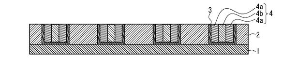
- FIG. 3 is a schematic cross-sectional view showing an example of a state after a resin layer is formed inside the side surface of the hole in FIG. 2. It is typical sectional drawing which shows an example of the state after phase-separating the resin layer in FIG.
- FIG. 5 is a schematic cross-sectional view showing an example of a state after removing a part of the phase of the phase separated resin layer in FIG. 4.
- the contact hole pattern forming method includes a step of forming a hole pattern on one surface side of the substrate (hereinafter also referred to as “hole pattern forming step”), and an annular composition in plan view so as to follow the side surface of the hole of the hole pattern.
- the step of applying the object (I) (hereinafter also referred to as “application step”), the composition (II) on one side of the substrate and the inner side of the hole on which the composition (I) is applied
- a step of forming a resin layer (hereinafter also referred to as “resin layer forming step”), a step of phase-separating the resin layer (hereinafter also referred to as “resin layer forming step”), and a part of the phase separated resin layer
- a step (hereinafter, also referred to as “removing step”) of removing the phase of the above.
- the contact hole pattern forming method further includes a step of removing at least a part of the coating film formed of the composition (I) (hereinafter, also referred to as “coating film removing step”) after the coating step. It is preferable.
- the contact hole pattern forming method is a step of forming a substrate pattern (contact hole) by etching using the resin layer (I) after the removing step as a mask after the removing step (hereinafter referred to as “substrate pattern forming step”). May also be provided.
- Contact hole refers to a through hole provided in a direction perpendicular to the surface of the substrate in order to connect each element formed on the substrate.
- the “contact hole pattern” refers to a pattern that serves as a mask for forming the contact hole in the substrate.
- This step is a step of forming a hole pattern on one surface side of the substrate.
- this hole pattern may be directly formed on one surface of the substrate 1, and a lower layer film, a spin-on-glass (SOG) film and / or a resist film are formed on the substrate, and these films are formed. It may be formed directly on the surface opposite to the substrate 1. From the viewpoint that a contact hole can be easily formed in the substrate by etching using the formed contact hole pattern as a mask, the hole pattern is preferably formed directly on one surface of the substrate 1. It is more preferable to form a hole pattern in the lower layer film after directly forming the lower layer film.
- Examples of the method for forming a hole pattern in the lower layer film include the following methods.
- a lower layer film is formed on one surface side of the substrate 1 using the lower layer film forming composition.
- an SOG film may be formed on the surface of the lower film opposite to the substrate 1 by using an SOG composition.
- a resist film is formed on the surface of the lower layer film or SOG film opposite to the substrate 1 by using a resist composition.
- the resist film is exposed and developed to form a hole-like resist pattern. Using the hole-shaped resist pattern as a mask, the SOG film and / or the lower layer film are sequentially etched.
- the substrate for example, a conventionally known substrate such as a silicon (Bare-Si) wafer or a wafer coated with aluminum can be used.
- underlayer film forming composition conventionally known organic underlayer film forming materials and the like can be used, and examples thereof include an underlayer film forming composition containing a crosslinking agent.
- the method for forming the lower layer film is not particularly limited.
- the coating film obtained after applying the composition for forming the lower layer film to one surface of the substrate by a known method such as a spin coating method and performing pre-baking (PB) The method of hardening
- radiation to be irradiated include electromagnetic waves such as visible light, ultraviolet light, far ultraviolet light, X-rays, and ⁇ rays; particle beams such as electron beams, molecular beams, and ion beams.
- 90 ° C is preferred, 120 ° C is more preferred, and 150 ° C is still more preferred.
- the lower limit of the heating time is preferably 5 seconds, more preferably 10 seconds, and even more preferably 20 seconds.
- the upper limit of the heating time is preferably 1,200 seconds, more preferably 600 seconds, and even more preferably 300 seconds.
- 10 nm is preferred, 30 nm is more preferred, and 50 nm is still more preferred.
- the upper limit of the average thickness is preferably 1,000 nm, more preferably 500 nm, and even more preferably 200 nm.
- SOG composition a conventionally known SOG composition or the like can be used, and examples thereof include a composition containing an organic polysiloxane.
- a method for forming the SOG film is not particularly limited.
- the SOG composition is applied to one surface of the substrate or the surface of the lower layer opposite to the substrate 1 by a known method such as spin coating, and PB is coated.
- Examples thereof include a method of curing the obtained coating film by irradiating radiation and / or heating.
- radiation to be irradiated include electromagnetic waves such as visible light, ultraviolet light, far ultraviolet light, X-rays, and ⁇ rays; particle beams such as electron beams, molecular beams, and ion beams.
- 100 ° C is preferred, 150 ° C is more preferred, and 180 ° C is still more preferred.
- the lower limit of the heating time is preferably 5 seconds, more preferably 10 seconds, and even more preferably 20 seconds.
- the upper limit of the heating time is preferably 1,200 seconds, more preferably 600 seconds, and even more preferably 300 seconds.
- the lower limit of the average thickness of the SOG film is preferably 10 nm, more preferably 15 nm, and still more preferably 20 nm.
- the upper limit of the average thickness is preferably 1,000 nm, more preferably 500 nm, and still more preferably 100 nm.
- a conventional resist composition such as a polymer containing an acid-dissociable group, a radiation-sensitive acid generator, and a solvent-containing composition can be used.
- a resist composition is applied to one surface of the substrate 1, the surface of the lower layer opposite to the substrate 1, or the surface of the SOG film opposite to the substrate 1, and then prebaked (PB ) To form a resist film.
- exposure is performed through a mask pattern for forming a hole pattern of a desired shape.
- radiation used for exposure include ultraviolet rays, far ultraviolet rays, extreme ultraviolet rays (EUV), electromagnetic waves such as X-rays, and charged particle beams such as electron beams and ⁇ rays.
- far ultraviolet rays are preferable, ArF excimer laser light and KrF excimer laser are more preferable, and ArF excimer laser light is more preferable.
- immersion exposure can also be performed. It is preferable to perform post-exposure baking (PEB) after exposure.
- PEB post-exposure baking
- development is performed using a developer such as an alkali developer or an organic solvent.
- the lower limit of the average thickness of the resist film is preferably 10 nm, more preferably 30 nm, and even more preferably 50 nm.
- the upper limit of the average thickness is preferably 1,000 nm, more preferably 500 nm, and even more preferably 200 nm.
- the shape of the hole pattern 2 can be appropriately selected according to the shape of the contact hole finally formed on the substrate.
- a circular shape such as a perfect circle shape or an elliptical shape; a square shape, a rectangular shape, a trapezoidal shape, or the like
- a polygonal shape such as a triangular shape such as a quadrangular shape, an equilateral triangular shape, and an isosceles triangular shape.
- a circular shape is preferable and a perfect circular shape is more preferable from the viewpoint that a contact hole pattern can be more easily formed using the [A ′] polymer that is a block copolymer.
- the lower limit of the average diameter of the hole pattern 2 to be formed is preferably 10 nm, more preferably 20 nm, still more preferably 30 nm, and particularly preferably 40 nn.
- the upper limit of the average diameter is preferably 200 nm, more preferably 100 nm, still more preferably 90 nm, and particularly preferably 80 nm.
- the obtained hole pattern 2 is preferably accelerated by a treatment in which, for example, after irradiation with ultraviolet rays of 254 nm or the like, heating is performed at 100 ° C. to 200 ° C. for 1 minute to 30 minutes.
- the inner surface of the hole of the hole pattern 2 may be subjected to a hydrophobic treatment or a hydrophilic treatment.
- a hydrogenation treatment by exposing to hydrogen plasma for a certain period of time can be cited.
- the phase separation of the second resin layer can be further promoted by increasing the hydrophobicity or hydrophilicity of the inner surface of the hole of the hole pattern 2.
- This step is a step of applying the composition (I) in a ring shape in plan view so as to follow the side surface of the hole of the hole pattern 2 as shown in FIG.
- the composition (I) will be described later.
- a coating film is formed in an annular shape in plan view from the composition (I).
- the composition (I) is directly applied to the side surface of the hole of the hole pattern 2.
- the composition (I) may be applied to the bottom surface of the hole pattern 2, that is, one surface side of the substrate 1 other than the side surface of the hole of the hole pattern 2.
- the composition (I) is applied to the inside of the side surface of the hole of the hole pattern 2, and a coating film is formed by performing PB or the like.
- the coating method include a spin coating method.
- the substrate on which the coating film is formed is heated.
- the heating means include an oven and a hot plate.
- 80 ° C is preferred, 100 ° C is more preferred, and 150 ° C is still more preferred.
- 400 degreeC is preferable, 350 degreeC is more preferable, and 300 degreeC is further more preferable.
- 10 seconds are preferred, 20 seconds are more preferred, and 30 seconds are still more preferred.
- the upper limit of the heating time is preferably 120 minutes, more preferably 10 minutes, and even more preferably 5 minutes.
- the lower limit of the average thickness of the coating film on the side surface to be formed is preferably 1 nm, more preferably 5 nm, and even more preferably 10 nm.
- the upper limit of the average thickness is preferably 50 nm, more preferably 40 nm, and even more preferably 30 nm.
- This step is a step of removing at least part of the coating film formed of the composition (I) after the coating step. By this step, a portion of the coating film that does not interact with the side surface of the hole pattern is removed.
- a method of cleaning the coating film using a solvent can be mentioned.
- a solvent what was illustrated as a solvent which composition (II) mentioned later contains, for example is mentioned.
- polyhydric alcohol partial ether carboxylate solvents are preferable, and propylene glycol monomethyl ether acetate is more preferable.
- the lower limit of the average thickness of the coating film after the coating film removing step is preferably 0.1 nm, more preferably 0.5 nm, still more preferably 1 nm, and particularly preferably 2 nm.
- the upper limit of the average thickness is preferably 10 nm, more preferably 8 nm, still more preferably 6 nm, and particularly preferably 4 nm.
- the application step can be performed once or a plurality of times.
- it can carry out once or several times for every after the said coating process.
- the side surface of the hole immediately before the next resin layer forming step that is, after the coating film removing step when the coating film removing step is performed, and after the coating step when the coating film removing step is not performed.
- the static contact angle A (°) with water satisfies the following formula (1).
- a is a static contact angle (°) with water in a film-forming state of a homopolymer composed only of the structural unit (I).
- b is a static contact angle (°) with water in a film-forming state of a homopolymer composed only of the structural unit (II).
- the static contact angle A with the water on the side surface of the hole immediately before the resin layer forming step, and the single unit comprising only the structural unit (I) in the [A ′] polymer satisfy the above formula (1). Even when the hole diameter is small, it is considered that the phase separation of the resin layer (I) 4 formed in this phase separation step is more favorably caused, and as a result, the placement error is suppressed and the bottom residue is reduced.
- a contact hole pattern can be formed. Although the reason for this is not necessarily clear, for example, in the resin layer forming step, it is considered that the surface of the coating film formed inside the hole pattern 2 and the resin layer (I) 4 interact moderately. .
- the lower limit of A in the above formula (1) is (a + b) / 2, preferably 0.52 (a + b), more preferably 0.54 (a + b), and still more preferably 0.55 (a + b).
- the upper limit of A is a, preferably 0.995a, more preferably 0.99a, and still more preferably 0.985a.
- the [A ′] polymer of the composition (II) described later is a styrene-methyl methacrylate diblock copolymer (a in the above formula (1) is 90 °, b is 65 °), the above formula (1 ) Is preferably 78 °, more preferably 80 °, and still more preferably 82 °.
- the upper limit of A is preferably 90 °, more preferably 89.0 °.
- a resin layer (I) 4 is formed from the composition (II) on one side of the substrate 1 and inside the side of the hole where the composition (I) is applied. It is a process to do. That is, the resin layer (I) 4 is formed on one surface side of the substrate 1 and inside the hole in which the coating film of the composition (I) is formed.
- the resin layer (I) 4 is usually opposite to the substrate 1 of the coating film of the composition (I) directly laminated on one surface side of the substrate 1, that is, directly above one surface of the substrate 1 or the like. Immediately above the side surface and inside the coating film of the composition (I) on the side surface of the hole.
- the resin layer (I) 4 is formed by applying the composition (II) to the inside of the coating film 3 of the composition (I) formed on the side surface of the hole pattern 2 by spin coating or the like, and performing PB. can do.
- the average height of the resin layer (I) 4 is not particularly limited, but is preferably equal to the average height of the hole pattern 2.
- composition (II) contains a [A ′] polymer and a [B] solvent.
- Composition (II) may contain other components other than the [A ′] polymer and the [B] solvent as long as the effects of the present invention are not impaired.
- each component will be described.
- the polymer is a block copolymer having a block (I) having the structural unit (I) and a structural unit (II) having a higher polarity than the structural unit (I).
- the polymer may have a block other than the block (I) and the block (II). Moreover, the [A '] polymer may have a connection part between these blocks.
- the “linkage site” refers to a site that is formed of, for example, 1,1-diphenylethylene and is not a block.
- the polymer may be a diblock polymer or a polymer having three or more blocks such as a triblock polymer. Among these, a diblock polymer is preferable from the viewpoint of forming a contact hole pattern more easily.
- the block (I) has a structural unit (I).
- the block (II) has a structural unit (II) having a higher polarity than the structural unit (I).
- the monomer which gives each structural unit differs between block (I) and block (II), and the monomer which gives structural unit (II) rather than the monomer which gives structural unit (I)
- the polarity is higher.
- the structural unit (I) and the structural unit (II) are, for example, substituted or unsubstituted styrene, (meth) acrylic acid ester, substituted or unsubstituted ethylene (provided that the above substituted or unsubstituted styrene and the above (meth) acrylic). Derived from those other than acid esters).
- substituted styrene examples include ⁇ -methylstyrene, o-, m-, p-methylstyrene, pt-butylstyrene, 2,4,6-trimethylstyrene, p-methoxystyrene, pt-butoxystyrene, o-, m-, p-vinylstyrene, o-, m-, p-hydroxystyrene, m-, p-chloromethylstyrene, p-chlorostyrene, p-bromostyrene, p-iodostyrene, p-nitrostyrene , P-cyanostyrene and the like.
- (meth) acrylic acid esters examples include (meth) acrylic acid alkyl esters such as methyl (meth) acrylate, ethyl (meth) acrylate, t-butyl (meth) acrylate, and 2-ethylhexyl (meth) acrylate. ; Cyclopentyl (meth) acrylate, cyclohexyl (meth) acrylate, 1-methylcyclopentyl (meth) acrylate, 2-ethyladamantyl (meth) acrylate, 2- (adamantan-1-yl) propyl (meth) acrylate, etc.
- substituted ethylene examples include alkenes such as propene, butene, and pentene; Vinylcycloalkanes such as vinylcyclopentane and vinylcyclohexane; Cycloalkenes such as cyclopentene and cyclohexene; Examples include 4-hydroxy-1-butene, vinyl glycidyl ether, vinyl trimethylsilyl ether, and the like.
- the structural unit (I) is preferably a structural unit derived from substituted or unsubstituted styrene, and more preferably a structural unit derived from unsubstituted styrene.
- the structural unit (II) is preferably a structural unit derived from (meth) acrylic acid ester, more preferably a structural unit derived from (meth) acrylic acid alkyl ester, and a structural unit derived from methyl (meth) acrylate. Further preferred.
- a contact hole pattern in which generation of a placement error and a bottom residue is further suppressed can be formed.
- the molar ratio of the structural unit (I) to the structural unit (II) in the [A ′] polymer is not particularly limited, but the lower limit of this molar ratio is preferably 10/90, more preferably 20/80.
- the upper limit of the molar ratio is preferably 90/10, and more preferably 80/20.
- the lower limit of the content of the [A ′] polymer in the composition (II) is preferably 80% by mass with respect to the total solid content in the composition (II) (total of components other than the [B] solvent). 90 mass% is more preferable, and 95 mass% is still more preferable.
- the composition (II) may contain one or more [A ′] polymers, but one is preferred.
- the polymer can be synthesized by, for example, living cationic polymerization, living anionic polymerization, living radical polymerization, coordination polymerization (Ziegler-Natta catalyst, metallocene catalyst) and the like.
- living anionic polymerization is preferable from the viewpoint that the obtained [A ′] polymer can be controlled to a more desired block structure.
- Examples of the solvent used for anionic polymerization include alkanes such as n-pentane, n-hexane, n-heptane, n-octane, n-nonane, and n-decane; Cycloalkanes such as cyclohexane, cycloheptane, cyclooctane, decalin, norbornane; Aromatic hydrocarbons such as benzene, toluene, xylene, ethylbenzene, cumene; Saturated carboxylic acid esters such as ethyl acetate, n-butyl acetate, i-butyl acetate and methyl propionate; Ketones such as acetone, 2-butanone, 4-methyl-2-pentanone, 2-heptanone, cyclohexanone; Examples include ethers such as tetrahydrofuran, dimethoxyethanes, and
- the reaction temperature in the anionic polymerization can be appropriately selected according to the type of the anionic polymerization initiator, but the lower limit of the reaction temperature is preferably ⁇ 150 ° C., more preferably ⁇ 80 ° C.
- As an upper limit of reaction temperature 50 degreeC is preferable and 40 degreeC is more preferable.
- As a minimum of reaction time 5 minutes are preferred and 20 minutes are more preferred.
- the upper limit of the reaction time is preferably 24 hours, and more preferably 12 hours.
- Anionic polymerization initiators used for anionic polymerization include, for example, alkyl lithium, alkyl magnesium halide, sodium naphthalene, alkylated lanthanoid compounds; potassium alkoxides such as potassium t-butoxy and 18-crown-6-ether potassium; Alkyl zinc such as dimethyl zinc and diethyl zinc; Alkyl aluminums such as trimethylaluminum; Aromatic metal compounds such as benzyl potassium, cumyl potassium, cumyl cesium and the like can be mentioned. Of these, alkyl lithium is preferred.
- [A ′] polymer formed by polymerization is preferably recovered by a reprecipitation method. That is, after completion of the reaction, the target polymer is recovered as a powder by introducing the reaction solution into a reprecipitation solvent.
- a reprecipitation solvent alcohol, ultrapure water, alkane or the like can be used alone or in admixture of two or more.
- the polymer can be recovered by removing low molecular weight components such as monomers and oligomers by a liquid separation operation, a column operation, an ultrafiltration operation, or the like.
- the lower limit of the weight average molecular weight (Mw) in terms of polystyrene by gel permeation chromatography (GPC) of the polymer is preferably 3,000, more preferably 10,000, still more preferably 30,000, 50 Is particularly preferred.
- the upper limit of Mw is preferably 500,000, more preferably 300,000, still more preferably 200,000, and particularly preferably 100,000.
- the lower limit of the polystyrene-reduced number average molecular weight (Mn) of the [A ′] polymer is preferably 3,000, more preferably 10,000, further preferably 30,000, and particularly preferably 50,000.
- the upper limit of Mn is preferably 500,000, more preferably 300,000, still more preferably 200,000, and particularly preferably 100,000.
- the upper limit of the degree of dispersion (Mw / Mn) of the polymer is preferably 5, more preferably 3, more preferably 2, more preferably 1.5, still more preferably 1.2, and even more preferably 1. 1 is most preferred.
- the lower limit of the degree of dispersion is usually 1.
- Mw and Mn of the polymer in this specification are GPC columns (for example, two “G2000HXL”, one “G3000HXL”, one “G4000HXL” manufactured by Tosoh Corporation), a flow rate of 1.0 mL / min, and an elution solvent tetrahydrofuran.
- This is a value measured by GPC using a differential refractometer as a detector and using a monodisperse polystyrene as a standard under analysis conditions of a sample concentration of 1.0 mass%, a sample injection amount of 100 ⁇ m, and a column temperature of 40 ° C.
- the [B] solvent contained in the composition (II) is not particularly limited as long as it is a solvent capable of dissolving or dispersing at least the [A ′] polymer and other components.
- Examples of the solvent include alcohol solvents, ether solvents, ketone solvents, amide solvents, ester solvents, hydrocarbon solvents, and the like.
- alcohol solvent examples include methanol, ethanol, n-propanol, iso-propanol, n-butanol, iso-butanol, sec-butanol, tert-butanol, n-pentanol, iso-pentanol, 2-methylbutanol, sec-pentanol, tert-pentanol, 3-methoxybutanol, n-hexanol, 2-methylpentanol, sec-hexanol, 2-ethylbutanol, sec-heptanol, 3-heptanol, n-octanol, 2-ethylhexanol , Sec-octanol, n-nonyl alcohol, 2,6-dimethyl-4-heptanol, n-decanol, sec-undecyl alcohol, trimethylnonyl alcohol, sec-tetradecyl alcohol, sec -und
- ether solvents examples include dialkyl ether solvents such as diethyl ether, dipropyl ether, and dibutyl ether; Cyclic ether solvents such as tetrahydrofuran and tetrahydropyran; And aromatic ring-containing ether solvents such as diphenyl ether and anisole.
- ketone solvent examples include acetone, methyl ethyl ketone, methyl-n-propyl ketone, methyl-n-butyl ketone, diethyl ketone, methyl-iso-butyl ketone, 2-heptanone, ethyl-n-butyl ketone, methyl-n-hexyl ketone, Linear ketone solvents such as di-iso-butyl ketone and trimethylnonanone; Cyclic ketone solvents such as cyclopentanone, cyclohexanone, cycloheptanone, cyclooctanone, methylcyclohexanone; Examples include 2,4-pentanedione, acetonylacetone, acetophenone, and the like.
- amide solvent examples include cyclic amide solvents such as N, N′-dimethylimidazolidinone and N-methylpyrrolidone; Examples thereof include chain amide solvents such as N-methylformamide, N, N-dimethylformamide, N, N-diethylformamide, acetamide, N-methylacetamide, N, N-dimethylacetamide, and N-methylpropionamide.
- cyclic amide solvents such as N, N′-dimethylimidazolidinone and N-methylpyrrolidone
- chain amide solvents such as N-methylformamide, N, N-dimethylformamide, N, N-diethylformamide, acetamide, N-methylacetamide, N, N-dimethylacetamide, and N-methylpropionamide.
- ester solvents include methyl acetate, ethyl acetate, n-propyl acetate, iso-propyl acetate, n-butyl acetate, iso-butyl acetate, sec-butyl acetate, n-pentyl acetate, i-pentyl acetate, sec Acetate solvents such as pentyl, 3-methoxybutyl acetate, methylpentyl acetate, 2-ethylbutyl acetate, 2-ethylhexyl acetate, benzyl acetate, cyclohexyl acetate, methylcyclohexyl acetate, n-nonyl acetate; Ethylene glycol monomethyl ether acetate, ethylene glycol monoethyl ether acetate, diethylene glycol monomethyl ether acetate, diethylene glycol monoethyl ether acetate, diethylene glycol mono-l
- hydrocarbon solvents examples include n-pentane, iso-pentane, n-hexane, iso-hexane, n-heptane, iso-heptane, 2,2,4-trimethylpentane, n-octane, iso-octane, cyclohexane , Aliphatic hydrocarbon solvents such as methylcyclohexane; Fragrances such as benzene, toluene, xylene, mesitylene, ethylbenzene, trimethylbenzene, methylethylbenzene, n-propylbenzene, iso-propylbenzene, diethylbenzene, iso-butylbenzene, triethylbenzene, di-iso-propylbenzene, n-amylnaphthalene Group hydrocarbon solvents and the like.
- ester solvents and ketone solvents are preferable, ester solvents are more preferable, polyhydric alcohol partial ether carboxylate solvents are more preferable, and propylene glycol monomethyl ether acetate is particularly preferable.
- the composition (II) may contain one or more solvents.
- composition (II) can contain other components such as a surfactant.
- Composition (II) can improve the applicability
- composition (II) is prepared, for example, by mixing [A ′] polymer, [B] solvent and other components as required at a predetermined ratio, and filtering through a membrane filter having a pore size of about 200 nm. can do.
- a membrane filter having a pore size of about 200 nm. can do.
- the upper limit of the solid content concentration is preferably 30% by mass, more preferably 10% by mass, and even more preferably 5% by mass.
- This step is a step of phase-separating the resin layer (I) 4.
- the [A ′] polymer is a diblock polymer, as shown in FIG. 4, by separating the resin layer (I) 4, the block ( ⁇ ) phase 4a composed of one block and the other The block ( ⁇ ) phase 4b is formed.
- Examples of the phase separation method include an annealing method.
- Examples of the annealing method include a method of heating with an oven, a hot plate or the like.
- As a minimum of the temperature of heating 80 ° C is preferred, 100 ° C is more preferred, and 150 ° C is still more preferred.
- As an upper limit of the said temperature 400 degreeC is preferable, 350 degreeC is more preferable, and 300 degreeC is further more preferable.
- As a minimum of heating time 10 seconds are preferred, 20 seconds are more preferred, and 30 seconds are still more preferred.
- the upper limit of the time is preferably 120 minutes, more preferably 10 minutes, and even more preferably 5 minutes.
- This step is a step of removing a part of the phase of the separated resin layer (I) 4. As shown in FIG. 5, a contact hole having a hole diameter smaller than that of the hole pattern 2 is obtained by removing the central block ( ⁇ ) phase 4b from the phase formed by phase separation of the resin layer (I) 4. A pattern is formed.
- etching As a removal method, for example, CF 4 , O 2 gas or the like is used, chemical dry etching using a difference in etching rate of each phase, etc., chemical wet etching using a liquid etching solution such as an organic solvent or hydrofluoric acid.
- a liquid etching solution such as an organic solvent or hydrofluoric acid.
- RIE reactive ion etching
- physical etching such as sputter etching and ion beam etching.
- reactive ion etching is preferable, and chemical dry etching and chemical wet etching are more preferable.
- radiation Before chemical dry etching, radiation may be applied as necessary.
- the radiation when the phase to be removed by etching is a polymethyl methacrylate block phase, 172 nm radiation or the like can be used. Since the polymethyl methacrylate block phase is decomposed by this irradiation, it is more easily etched.
- organic solvents used for chemical wet etching include alkanes such as n-pentane, n-hexane, and n-heptane; Cycloalkanes such as cyclohexane, cycloheptane, cyclooctane; Saturated carboxylic acid esters such as ethyl acetate, n-butyl acetate, i-butyl acetate and methyl propionate; Ketones such as acetone, methyl ethyl ketone, methyl isobutyl ketone, methyl n-pentyl ketone; Examples thereof include alcohols such as methanol, ethanol, 1-propanol, 2-propanol and 4-methyl-2-pentanol. These solvents may be used alone or in combination of two or more.
- This step is a step of forming a substrate pattern (contact hole) by etching using the second resin layer after the removing step as a mask. This etching is performed on the lower layer film and the substrate when the lower layer film is formed, and is performed on the substrate when the lower layer film is not formed.
- an etching method a method similar to the above-described removal step can be used, and an etching gas and an etching solution can be appropriately selected depending on the material of the substrate.
- a mixed gas of chlorofluorocarbon gas and SF 4 can be used.
- a mixed gas of BCl 3 and Cl 2 or the like can be used.
- phase (block ( ⁇ ) phase 4a) used as a mask is removed from one surface side of the substrate by dissolution treatment or the like, and a substrate in which contact holes are finally formed can be obtained.
- a substrate obtained by the contact hole pattern forming method is suitably used for a semiconductor element or the like, and the semiconductor element is widely used for an LED, a solar cell or the like.
- composition (I) to be applied in the application step will be described.
- composition (I) contains a [A] polymer and a [B] solvent.
- Composition (I) preferably contains [C] a radiation-sensitive acid generator (hereinafter also referred to as “[C] acid generator”), and [A] within a range not impairing the effects of the present invention.
- [C] acid generator a radiation-sensitive acid generator
- the structure of the polymer is such that the static contact angle A with the water on the side surface of the hole immediately before the resin layer forming step after applying the composition (I) satisfies the above formula (1).
- the polymer may have, in addition to the structural unit (I), the structural unit (II) contained in the [A ′] polymer of the composition (II).
- the structural unit (II) And may have a structural unit (III) having a different structure other than a portion derived from a polymerizable group.
- the polymer may have other structural units other than the structural units (I) to (III).
- the polymer may be a homopolymer or a copolymer.
- the polymer when it is a copolymer, it may be a random copolymer, a block copolymer, or a polymer having a gradient structure. That is, in the [A] polymer, the structural units (I) to (III) and other structural units may or may not form a block structure. Hereinafter, each structural unit will be described.
- the structural unit (I) is the same as the structural unit (I) of the [A ′] polymer contained in the composition (II).
- the structural unit (I) is as described in the section of the structural unit (I) of the above [A ′] polymer.
- the structural unit (I) in the polymer is preferably a structural unit derived from substituted or unsubstituted styrene, and more preferably a structural unit derived from unsubstituted styrene.
- the structural unit (II) is the same as the structural unit (II) of the [A ′] polymer contained in the composition (II).
- the structural unit (II) is as described in the section of the structural unit (II) of the above [A ′] polymer.
- a structural unit derived from (meth) acrylic acid ester is preferable, and a structural unit derived from methyl (meth) acrylate is more preferable.
- the structural unit (III) is different from the structural unit (II) except for the portion derived from the polymerizable group.
- “Polymerizable group” refers to a group that enables a polymerization reaction, and includes, for example, a group containing an ethylenic carbon-carbon double bond. Specific examples include a styryl group, a (meth) acryloyl group, a vinyl group. Groups and the like.
- Examples of the group included in the structure other than the portion derived from the polymerizable group include a hydroxy group, a sulfanyl group, an amino group, and an amide group. Among these, a hydroxy group and a sulfanyl group (hereinafter collectively referred to as “first group” (group (I))) are preferable.
- Examples of the structural unit (III) include (meth) acrylic acid hydroxyalkyl esters such as hydroxyethyl (meth) acrylate, hydroxypropyl (meth) acrylate, and hydroxybutyl (meth) acrylate; hydroxycyclohexyl (meth) acrylate (Meth) acrylic acid hydroxycycloalkyl esters such as methyl; (meth) acrylic acid hydroxy hydrocarbon esters such as (meth) acrylic acid hydroxyphenyl, (meth) acrylic acid hydroxy aromatic esters such as hydroxybenzyl Such; (Meth) acrylic acid sulfanylethyl, (meth) acrylic acid sulfanylpropyl, (meth) acrylic acid sulfanylbutyl and other (meth) acrylic acid sulfanyl alkyl esters; (meth) acrylic acid sulfanylcyclohexylmethyl (meth) acrylic acid sulfanyl Cycloalkyl esters; structural units
- the structural unit (III) is preferably a structural unit derived from (meth) acrylic acid hydroxyalkyl ester and (meth) acrylic acid sulfanylalkyl ester, and derived from (meth) acrylic acid hydroxyethyl and (meth) acrylic acid sulfanylethyl.
- the structural unit is more preferable.
- the polymer is preferably a polymer having the structural unit (I) and the structural unit (III), more preferably a polymer having a gradient polymer structure of the structural unit (I) and the structural unit (III), A polymer having a gradient polymer structure of the structural unit (I) and the structural unit (III) containing the group (I) is more preferable.
- the [A] polymer a polymer having the structural unit (I) and the structural unit (II) is also preferable.
- the [A] polymer a polymer in which the group (I) is bonded to at least one terminal of the main chain is also preferable.
- Examples of the group (I) bonded to the terminal of the polymer include a group represented by -X- (Y) n (n is an integer of 1 to 3).
- X is an (n + 1) -valent hydrocarbon group having 1 to 20 carbon atoms.
- Y is —OH, —SH, a cyclic ether group, a cyano group, a carboxy group, an alkoxy group, or a vinyl group.
- Examples of the (n + 1) -valent hydrocarbon group having 1 to 20 carbon atoms represented by X include chain hydrocarbons having 1 to 20 carbon atoms such as alkanes such as methane, ethane and propane; Alicyclic hydrocarbons having 3 to 20 carbon atoms such as cycloalkane such as cyclopentane, cyclohexane, methylcyclohexane, etc .; And groups obtained by removing (n + 1) hydrogen atoms from aromatic hydrocarbons having 6 to 20 carbon atoms such as benzene, naphthalene, toluene and ethylbenzene.
- alkanediyl groups groups derived from chain hydrocarbons and aromatic hydrocarbons are preferred, alkanediyl groups, alkanetriyl groups and aromatic ring-bonded alkanediyl groups are more preferred, methanediyl groups, ethanediyl groups, propanediyl groups, A propanetriyl group and a phenylethanediyl group are more preferred.
- Examples of the cyclic ether group represented by Y include an oxiranyl group, an oxetanyl group, an oxacyclopentyl group, and an oxacyclohexyl group. Among these, an oxiranyl group and an oxetanyl group are preferable, and an oxiranyl group is more preferable.
- Examples of the alkoxy group represented by Y include methoxy group, ethoxy group, propoxy group, butoxy group, pentyloxy group, 2-ethylhexyloxy group and the like. Of these, a methoxy group, an ethoxy group, and a 2-ethylhexyloxy group are preferable.
- Examples of the group (I) bonded to the terminal of the polymer include a group represented by the following formula, 2-hydroxy-3-methoxypropyl group, 2-hydroxy-3- (2-ethylhexyloxy) propyl group 2,3-dihydroxypropyl group, hydroxyethyl group and the like.
- Examples of the group (I) bonded to the terminal of the polymer include 2-hydroxy-2-phenylethyl group, 2-sulfanylpropyl group, allyl group, 2-hydroxy-3-methoxypropyl group, 2-hydroxy- 3- (2-ethylhexyloxy) propyl group, 2,3-dihydroxypropyl group and hydroxyethyl group are preferred.
- [A] The same polymer as the [A ′] polymer of the composition (II) can also be used.
- the same [A] polymer and [A ′] polymer it is possible to easily form a contact hole pattern in which placement errors are suppressed and bottom residue is reduced. It becomes possible.
- the same composition (I) and composition (II) can be used (double coating). This double coating makes it possible to more easily form a contact hole pattern in which placement errors are suppressed and bottom residue is reduced.
- the lower limit of the content of the [A] polymer in the composition (I) is preferably 80% by mass with respect to the total solid content in the composition (I) (total of components other than the [B] solvent), 90 mass% is more preferable, and 95 mass% is further more preferable.
- Composition (I) may contain one or more [A] polymers, but one is preferred.
- the polymer can be synthesized by a known polymerization method.
- the polymer is a block copolymer, a homopolymer, or a polymer in which a predetermined group is bonded to at least one terminal of the main chain.
- the above-mentioned [A ′] polymer synthesis method is described. It can be synthesized by the method.
- the polymer is a random copolymer or a copolymer having a gradient structure
- a monomer that gives each structural unit is synthesized by polymerizing in a suitable solvent using a radical polymerization initiator or the like. can do.
- radical polymerization initiator examples include azobisisobutyronitrile (AIBN), 2,2′-azobis (4-methoxy-2,4-dimethylvaleronitrile), 2,2′-azobis (2-cyclopropyl). Azo radical initiators such as propionitrile), 2,2′-azobis (2,4-dimethylvaleronitrile), dimethyl 2,2′-azobisisobutyrate; And peroxide radical initiators such as benzoyl peroxide, t-butyl hydroperoxide and cumene hydroperoxide. Of these, AIBN and dimethyl 2,2′-azobisisobutyrate are preferred, and AIBN is more preferred. These radical polymerization initiators can be used alone or in combination of two or more.
- Examples of the solvent used for the polymerization include alkanes such as n-pentane, n-hexane, n-heptane, n-octane, n-nonane and n-decane; Cycloalkanes such as cyclohexane, cycloheptane, cyclooctane, decalin, norbornane; Aromatic hydrocarbons such as benzene, toluene, xylene, ethylbenzene, cumene; Halogenated hydrocarbons such as chlorobutane, bromohexane, dichloroethane, hexamethylene dibromide, chlorobenzene; Saturated carboxylic acid esters such as ethyl acetate, n-butyl acetate, i-butyl acetate and methyl propionate; Ketones such as acetone, methyl ethyl ketone,
- the lower limit of the reaction temperature in the polymerization is preferably 40 ° C, more preferably 50 ° C.
- 150 degreeC is preferable and 120 degreeC is more preferable.
- 1 hour is preferable and 2 hours is more preferable.
- the upper limit of the reaction time is preferably 48 hours, more preferably 24 hours.
- the polymer formed by polymerization is preferably recovered by a reprecipitation method. That is, after completion of the reaction, the target polymer is recovered as a powder by introducing the reaction solution into a reprecipitation solvent.
- a reprecipitation solvent alcohol, ultrapure water, alkane or the like can be used alone or in admixture of two or more.
- the polymer can be recovered by removing low molecular weight components such as monomers and oligomers by a liquid separation operation, a column operation, an ultrafiltration operation, or the like.
- Mw of a polymer As a minimum of Mw of a polymer, 3,000 is preferred, 4,000 is more preferred, 5,000 is still more preferred, and 6,000 is especially preferred.
- the upper limit of the Mw is preferably 500,000, more preferably 100,000, still more preferably 30,000, and particularly preferably 10,000.
- the lower limit of Mn of the polymer is preferably 2,500, more preferably 3,000, still more preferably 4,000, and particularly preferably 5,000.
- the upper limit of Mn is preferably 400,000, more preferably 80,000, further preferably 25,000, and particularly preferably 9,000.
- the upper limit of the degree of polymer dispersion (Mw / Mn) is preferably 5, more preferably 3, more preferably 2, more preferably 1.5, still more preferably 1.2, and even more preferably 1.1. Is most preferred.
- the lower limit of the degree of dispersion is usually 1.
- the [B] solvent contained in the composition (I) is not particularly limited as long as it is a solvent capable of dissolving or dispersing at least the [A] polymer, the [C] acid generator and other components.
- Examples of the [B] solvent contained in the composition (I) include the same solvents as those exemplified as the [B] solvent contained in the composition (II).
- composition (I) As the solvent [B] contained in the composition (I), ester solvents and ketone solvents are preferable, polyhydric alcohol partial ether carboxylate solvents and cyclic ketone solvents are more preferable, propylene glycol monomethyl ether acetate and cyclohexanone. Is more preferable.
- Composition (I) may contain one or more solvents.
- the acid generator is a substance that generates acid upon irradiation with radiation.
- the [A] polymer in the coating film formed in the coating step and the material constituting the lower layer film having the hole pattern 2 and / or the resin layer (I) 4 are configured [ A ′]
- the interaction with the polymer is promoted, and as a result, a contact hole pattern in which the placement error is further suppressed and the bottom residue is further reduced can be formed.
- Examples of the [C] acid generator include onium salt compounds, N-sulfonyloxyimide compounds, halogen-containing compounds, diazoketone compounds, and the like.
- Examples of the onium salt compounds include sulfonium salts, iodonium salts, tetrahydrothiophenium salts, phosphonium salts, diazonium salts, pyridinium salts, and the like.
- the [C] acid generator is preferably an onium salt, more preferably an iodonium salt, and even more preferably bis (4-t-butylphenyl) iodonium nonafluoro n-butanesulfonate.
- the composition (I) contains a [C] acid generator
- the lower limit of the content of [C] acid generator is preferably 0.1 parts by weight, more preferably 0.5 parts by weight, and even more preferably 1 part by weight with respect to 100 parts by weight of [A] polymer. 2 parts by mass is particularly preferred.
- the upper limit of the content is preferably 30 parts by mass, more preferably 20 parts by mass, further preferably 10 parts by mass, and particularly preferably 8 parts by mass.
- composition (I) can contain other components such as a surfactant.
- Composition (I) can improve the applicability
- composition (I) is, for example, a [A] polymer, a [B] solvent, and optionally a [C] acid generator and other components mixed at a predetermined ratio, preferably a membrane filter having a pore size of about 200 nm, etc. It can prepare by filtering with.
- a minimum of solid content concentration of composition (I) 0.1 mass% is preferred, 0.3 mass% is more preferred, and 0.5 mass% is still more preferred.
- the upper limit of the solid content concentration is preferably 30% by mass, more preferably 10% by mass, and even more preferably 5% by mass.
- Mw and Mn of the polymer are measured by gel permeation chromatography (GPC) using Tosoh's GPC columns ("G2000HXL", “G3000HXL” and “G4000HXL”) under the following conditions. did.
- Eluent Tetrahydrofuran (Wako Pure Chemical Industries)
- Flow rate 1.0 mL / min
- Sample concentration 1.0% by mass
- Sample injection volume 100 ⁇ L
- Detector Differential refractometer Standard material: Monodisperse polystyrene
- 13 C-NMR analysis 13 C-NMR analysis was performed using a nuclear magnetic resonance apparatus (“JNM-EX400” manufactured by JEOL Ltd.) and DMSO-d 6 as a measurement solvent. The content ratio of each structural unit in the polymer was calculated from the area ratio of the peak corresponding to each structural unit in the spectrum obtained by 13 C-NMR.
- This polymer was dried under reduced pressure at 60 ° C. to obtain 14.7 g of a white polymer represented by the following formula (A-5).
- This polymer (A-5) had Mw of 5,600, Mn of 5,300, and Mw / Mn of 1.06.
- the resulting polymerization reaction liquid was filtered through Celite to remove the copper complex, and washing was repeated 3 times using 500 g of a 1% by mass aqueous oxalic acid solution.
- the organic layer was collected and concentrated, and a solid obtained by adding 50 g of THF to the resulting concentrate was dropped into 1,000 g of methanol.
- the obtained solid was recovered with a Buchner funnel and washed with 50 g of methanol.
- the obtained solid was dried under reduced pressure to obtain 11.4 g of a white polymer represented by the following formula (A-6).
- This polymer (A-6) had Mw of 5,600, Mn of 4,600, and Mw / Mn of 1.22.
- the content ratios of the structural unit derived from styrene, the structural unit derived from methyl methacrylate and the structural unit derived from 2-hydroxyethyl methacrylate were 68 mol%, 10 mol% and A copolymer having a random copolymer portion containing 22% by mole of a structural unit derived from styrene and a structural unit derived from methyl methacrylate, and a block composed of a structural unit derived from 2-hydroxyethyl methacrylate; there were.
- the polymerization reaction solution was warmed to room temperature, concentrated, and then replaced with MIBK. Thereafter, 1,000 g of a 2% by mass oxalic acid aqueous solution was injected and stirred, and after standing, the lower aqueous layer was removed. This operation was repeated three times to remove the Li salt. Thereafter, 1,000 g of ultrapure water was injected and stirred, and the lower aqueous layer was removed. This operation was repeated three times to remove oxalic acid, and then the obtained solution was concentrated and dropped into 500 g of methanol to precipitate a polymer, and a solid was recovered with a Buchner funnel. This polymer was dried under reduced pressure at 60 ° C. to obtain 14.3 g of a white polymer represented by the following formula (A-7). This polymer (A-7) had Mw of 6,000, Mn of 5,800, and Mw / Mn of 1.03.
- This polymer (A-8) was a random copolymer having Mw of 5,800, Mn of 4,600, and Mw / Mn of 1.26.
- the content ratios of structural units derived from styrene and structural units derived from methyl methacrylate were 50 mol% and 50 mol%, respectively.
- This operation was repeated three times, and oxalic acid was removed. Then, the solution was concentrated and dropped into 500 g of methanol to precipitate a polymer, and a solid was recovered with a Buchner funnel. This polymer was dried under reduced pressure at 60 ° C. to obtain 11.4 g of a white polymer represented by the following formula (A-9).
- This polymer (A-9) had Mw of 5,700, Mn of 5,200, and Mw / Mn of 1.10.
- This operation was repeated three times, and oxalic acid was removed. Then, the solution was concentrated and dropped into 500 g of methanol to precipitate a polymer, and a solid was recovered with a Buchner funnel. This polymer was dried under reduced pressure at 60 ° C. to obtain 11.5 g of a white polymer represented by the following formula (A-10).
- This polymer (A-10) had Mw of 5,300, Mn of 5,000, and Mw / Mn of 1.06.
- 1,1-diphenylethylene (1.02 mL, 7.19 mmol) in this THF, 9.59 mL (4.79 mmol) of a 1M THF solution of lithium chloride, 2.47 mL of a 1N cyclohexane solution of sec-butyllithium (sec-BuLi) (2 Further, 12.7 mL (0.120 mol) of methyl methacrylate subjected to adsorption filtration with silica gel for removing the polymerization inhibitor and distilled and dehydrated was added dropwise over 30 minutes to polymerize. It was confirmed that the system was orange. At the time of this dropwise injection, care was taken so that the internal temperature of the reaction solution did not exceed -60 ° C.
- This operation was repeated three times, and oxalic acid was removed. Then, the solution was concentrated and dropped into 500 g of methanol to precipitate a polymer, and a solid was recovered with a Buchner funnel. This polymer was dried under reduced pressure at 60 ° C. to obtain 11.2 g of a white polymer represented by the following formula (A-13).
- This polymer (A-13) had Mw of 5,200, Mn of 5,000, and Mw / Mn of 1.04.
- the reaction was allowed to proceed for 120 minutes. Thereafter, 1 mL of methanol as a terminal terminator was injected to terminate the polymerization terminal.
- the polymerization reaction solution was warmed to room temperature, concentrated, and then replaced with MIBK. Thereafter, 1,000 g of a 2% by mass oxalic acid aqueous solution was injected and stirred, and after standing, the lower aqueous layer was removed. This operation was repeated three times to remove the Li salt. Thereafter, 1,000 g of ultrapure water was injected and stirred, and the lower aqueous layer was removed.
- This polymer (Aa) had Mw of 79,000, Mn of 77,000, and Mw / Mn of 1.03. As a result of 1 H-NMR analysis, the polymer (Aa) was found to contain 60.0 mol% and 40.0 mol, respectively, in the content ratios of the structural unit derived from styrene and the structural unit derived from methyl methacrylate. % Diblock copolymer.
- the reaction was allowed to proceed for 120 minutes. Thereafter, 1 mL of methanol as a terminal terminator was injected to terminate the polymerization terminal.
- the polymerization reaction solution was warmed to room temperature, concentrated, and then replaced with MIBK. Thereafter, 1,000 g of a 2% by mass oxalic acid aqueous solution was injected and stirred, and after standing, the lower aqueous layer was removed. This operation was repeated three times to remove the Li salt. Thereafter, 1,000 g of ultrapure water was injected and stirred, and the lower aqueous layer was removed.
- This polymer (Ab) had Mw of 79,000, Mn of 76,000, and Mw / Mn of 1.04. As a result of 1 H-NMR analysis, the polymer (Ab) was found to have a content ratio of structural units derived from styrene and structural units derived from methyl methacrylate of 64.0 mol% and 36.0 mol, respectively. % Diblock copolymer.
- composition (I) ⁇ Preparation of composition (I)> Components other than the [A] polymer used for the preparation of the composition (I) are shown below.
- composition (S-1)) [A] 100 parts by mass of (A-1) as a polymer, (B-1) 9,355 parts by mass and (B-2) 1,040 parts by mass as a solvent, and [C] acid generator (C-1) (5 parts by mass) was mixed, and the obtained mixed solution was filtered through a membrane filter having a pore size of 200 nm to prepare a composition (S-1).
- compositions (S-2) to (S-15) and (Sa) and (Sb)) In Preparation Example 1, compositions (S-2) to (S-15) and (Sa) were prepared in the same manner as Preparation Example 1, except that the components of the types and contents shown in Table 1 below were used. And (Sb) were prepared.
- an underlayer film having an average thickness of 85 nm was formed using an underlayer film forming composition (“HM710” from JSR), and an SOG composition (“ISX302” from JSR) was formed on the underlayer film. ) was used to form an SOG film having an average thickness of 30 nm.
- a 85 nm resist film is formed by applying a positive resist composition (“AIM5484JN” manufactured by JSR) to the obtained substrate, and ArF immersion exposure is performed, and an aqueous 2.38 mass% tetrabutylammonium hydroxide solution is used. And developed to form a resist pattern.
- the SOG film was etched using a mixed gas of CF 4 / O 2 / Air.
- the lower layer film was etched with a N 2 / O 2 mixed gas. Further, the SOG film remaining on the surface layer of the lower layer film pattern was peeled off with a dilute hydrofluoric acid solution to form a hole pattern having a hole size of 60 nm and a pitch of 150 nm in the lower layer film.
- composition (I) Application of composition (I)
- a track (“DSA ACT12” manufactured by Tokyo Electron Ltd.)
- the composition shown in Table 2 below was spin-coated at 1,500 rpm onto the hole pattern having the hole size of 60 nm and the pitch of 150 nm, and the composition was spin-coated at 220 ° C. Baked for 2 seconds.
- unreacted substances and the like were removed by rinsing the fired substrate with propylene glycol monomethyl ether acetate (PGMEA) for 4 seconds.
- the average thickness (nm) of the coating film of the composition (I) was measured before and after the rinsing.
- the static contact angle measured by the method described later was evaluated as the static contact angle between the above-mentioned calcination (before rinsing) and the water on the side surface of the hole after rinsing.
- the static contact angle A with the water on the side surface of the hole immediately before the resin layer forming step is a value of “static contact angle with the water on the side surface of the hole after rinsing” in Table 2.
- the measured values of the static contact angle and the average thickness of the coating film are shown in Table 2 below.
- composition (Sa) as the composition (II) was spin-coated on the substrate after the rinsing at 1,500 rpm.
- the substrate was phase-separated by thermal annealing at 220 ° C. for 60 seconds under nitrogen.
- the static contact angle with water in the film-forming state of the homopolymer of styrene represented by a in the above formula (1) is 90 °
- the static contact angle with water in the film-forming state of the homopolymer of methyl methacrylate represented by b is 65 °.
- MIBK methyl isobutyl ketone
- IPA 2-propanol
- a contact hole pattern was formed by immersing for 5 minutes to dissolve and remove the phase composed of the poly (methyl methacrylate) block in the polymer (Aa).
- a photosensitive SOG composition (“DS492Y” manufactured by JSR) was spin-coated at 1,500 rpm on the substrate after the development, and then soft-baked at 80 ° C. for 30 seconds, and then 200 mJ / cm 2 with a KrF exposure machine. After irradiation with sol-gel, a sol-gel curing reaction was carried out at 80 ° C. for 120 seconds. After embedding the hole pattern in this way, the average thickness (nm) of the bottom residue was measured by cross-sectional SEM observation using a length measurement SEM. “(*)” In Table 2 below indicates that the measurement could not be performed.
- an underlayer film having an average thickness of 85 nm was formed using an underlayer film forming composition (“HM710” from JSR), and an SOG composition (“ISX302” from JSR) was formed on the underlayer film. ) was used to form an SOG film having an average thickness of 30 nm.
- An 85 nm resist film is formed by applying a positive resist composition (“AIM5484JN” manufactured by JSR) to the obtained substrate, and ArF is entirely exposed, using an aqueous 2.38 mass% tetrabutylammonium hydroxide solution.
- a target resin film was formed on the exposed lower layer film according to the above-described process (application of composition (I)). That is, the composition is spin-coated on the lower layer film at 1,500 rpm, baked at 220 ° C. for 60 seconds, and then the baked substrate is rinsed with propylene glycol monomethyl ether acetate (PGMEA) for 4 seconds. Thus, unreacted substances and the like were removed.
- the static contact angle values of the surface after the firing (before rinsing) and the surface after the rinsing were measured using a contact angle meter (“Drop Master DM-501” manufactured by Kyowa Interface Science Co., Ltd.).
- the application of the composition (I) was not performed, and only the formation of the resin layer, the phase separation, and the removal of some phases by the composition (II) were performed.
- the contact angle with water on the side surface of the hole immediately before forming the resin layer with the composition (II), that is, the contact angle with water of the lower layer film itself was 56 °.
- measured values of Placement error (x direction and y direction), average hole diameter (nm), and average bottom residue thickness (nm) are shown in Table 3 below.
- a contact hole pattern is formed by spin-coating the composition (Sa) as the composition (II), thermal annealing and development in the same manner as in Examples 1 to 6. did.
- measured values of Placement error (x direction and y direction), average hole diameter (nm) and bottom residue average thickness (nm) are shown in Table 4 below.
- the contact hole pattern forming method and composition of the present invention it is possible to form a contact hole pattern in which placement errors are suppressed and bottom residue is reduced even when the hole diameter is small. Therefore, these can be suitably used for lithography processes in manufacturing various electronic devices such as semiconductor devices and liquid crystal devices that are required to be further miniaturized.
Landscapes
- Chemical & Material Sciences (AREA)
- Physics & Mathematics (AREA)
- General Physics & Mathematics (AREA)
- Organic Chemistry (AREA)
- Health & Medical Sciences (AREA)
- Chemical Kinetics & Catalysis (AREA)
- Medicinal Chemistry (AREA)
- Polymers & Plastics (AREA)
- Spectroscopy & Molecular Physics (AREA)
- Life Sciences & Earth Sciences (AREA)
- Engineering & Computer Science (AREA)
- Materials Engineering (AREA)
- Wood Science & Technology (AREA)
- Photosensitive Polymer And Photoresist Processing (AREA)
- Optics & Photonics (AREA)
- Exposure Of Semiconductors, Excluding Electron Or Ion Beam Exposure (AREA)
- Drying Of Semiconductors (AREA)
- Internal Circuitry In Semiconductor Integrated Circuit Devices (AREA)
Abstract
Description

当該コンタクトホールパターンの形成方法は、基板の一方の面側にホールパターンを形成する工程(以下、「ホールパターン形成工程」ともいう)、上記ホールパターンのホールの側面に沿うよう平面視環状に組成物(I)を塗布する工程(以下、「塗布工程」ともいう)、上記基板の一方の面側かつ上記組成物(I)の塗布を行ったホールの側面の内側に組成物(II)により樹脂層を形成する工程(以下、「樹脂層形成工程」ともいう)、上記樹脂層を相分離させる工程(以下、「樹脂層形成工程」ともいう)、及び上記相分離した樹脂層の一部の相を除去する工程(以下、「除去工程」ともいう)を備える。
本工程は、基板の一方の面側にホールパターンを形成する工程である。このホールパターンは、図1に示すように、基板1の一方の面に直接形成してもよく、基板上に下層膜、スピンオングラス(SOG)膜及び/又はレジスト膜を形成し、これらの膜の基板1と反対側の面に直接形成してもよい。形成されるコンタクトホールパターンをマスクとするエッチングにより、簡便に基板にコンタクトホールを形成できる観点から、ホールパターンは、基板1の一方の面に直接形成することが好ましく、基板1の一方の面に直接、下層膜を形成した後、この下層膜にホールパターンを形成することがより好ましい。
本工程は、図2に示すように、ホールパターン2のホールの側面に沿うよう平面視環状に組成物(I)を塗布する工程である。組成物(I)については後述する。本工程により、組成物(I)から平面視環状に塗布膜が形成される。組成物(I)は、ホールパターン2のホールの側面に直接塗布される。組成物(I)は、ホールパターン2のホールの側面以外にもホールパターン2の底面、すなわち基板1の一方の面側等に塗布されてもよい。
本工程は、塗布工程の後に、上記組成物(I)により形成された塗布膜の少なくとも一部を除去する工程である。この工程により、塗布膜のうち、ホールパターンの側面と相互作用していない部分は除去される。

本工程は、図3に示すように、基板1の一方の面側かつ上記組成物(I)の塗布を行ったホールの側面の内側に組成物(II)により樹脂層(I)4を形成する工程である。すなわち、樹脂層(I)4は、基板1の一方の面側かつ上記組成物(I)の塗布膜が形成されたホールの内側に形成される。樹脂層(I)4は、通常、基板1の一方の面側、つまり基板1の一方の面の直上等又はこれらの面に直接積層された組成物(I)の塗布膜の基板1と反対側の面の直上、かつホールの側面の組成物(I)の塗布膜の内側に充填される。
組成物(II)は、[A’]重合体と、[B]溶媒とを含有する。組成物(II)は、本発明の効果を損なわない範囲において、[A’]重合体及び[B]溶媒以外のその他の成分を含有していてもよい。以下、各成分について説明する。
[A’]重合体は、構造単位(I)を有するブロック(I)及びこの構造単位(I)よりも極性が高い構造単位(II)を有するブロック共重合体である。[A’]重合体は、ブロック(I)及びブロック(II)以外の他のブロックを有していてもよい。また、[A’]重合体は、これらのブロック間に、連結部位を有していてもよい。「連結部位」とは例えば1,1-ジフェニルエチレン等により形成され、ブロックではない部位をいう。[A’]重合体は、ジブロック重合体でもよく、トリブロック重合体等の3以上のブロックを有する重合体でもよい。これらの中で、コンタクトホールパターンをより容易に形成する観点から、ジブロック重合体が好ましい。
ブロック(I)は、構造単位(I)を有する。ブロック(II)は、構造単位(I)よりも極性が高い構造単位(II)を有する。このように、ブロック(I)とブロック(II)とは、各構造単位を与える単量体が異なり、構造単位(I)を与える単量体よりも構造単位(II)を与える単量体の方が極性が高い。
(メタ)アクリル酸メチル、(メタ)アクリル酸エチル、(メタ)アクリル酸t-ブチル、(メタ)アクリル酸2-エチルヘキシル等の(メタ)アクリル酸アルキルエステル;
(メタ)アクリル酸シクロペンチル、(メタ)アクリル酸シクロヘキシル、(メタ)アクリル酸1-メチルシクロペンチル、(メタ)アクリル酸2-エチルアダマンチル、(メタ)アクリル酸2-(アダマンタン-1-イル)プロピル等の(メタ)アクリル酸シクロアルキルエステル;
(メタ)アクリル酸フェニル、(メタ)アクリル酸ナフチル等の(メタ)アクリル酸アリールエステル;
(メタ)アクリル酸2-ヒドロキシエチル、(メタ)アクリル酸3-ヒドロキシアダマンチル、(メタ)アクリル酸3-グリシジルプロピル、(メタ)アクリル酸3-トリメチルシリルプロピル等の(メタ)アクリル酸置換アルキルエステルなどが挙げられる。
プロペン、ブテン、ペンテン等のアルケン;
ビニルシクロペンタン、ビニルシクロヘキサン等のビニルシクロアルカン;
シクロペンテン、シクロヘキセン等のシクロアルケン;
4-ヒドロキシ-1-ブテン、ビニルグリシジルエーテル、ビニルトリメチルシリルエーテル等が挙げられる。
[A’]重合体は、例えばリビングカチオン重合、リビングアニオン重合、リビングラジカル重合、配位重合(チーグラー・ナッタ触媒、メタロセン触媒)等によって合成することができる。これらの中で、得られる[A’]重合体をより所望のブロック構造に制御できる観点から、リビングアニオン重合が好ましい。
n-ペンタン、n-ヘキサン、n-ヘプタン、n-オクタン、n-ノナン、n-デカン等のアルカン;
シクロヘキサン、シクロヘプタン、シクロオクタン、デカリン、ノルボルナン等のシクロアルカン;
ベンゼン、トルエン、キシレン、エチルベンゼン、クメン等の芳香族炭化水素;
酢酸エチル、酢酸n-ブチル、酢酸i-ブチル、プロピオン酸メチル等の飽和カルボン酸エステル;
アセトン、2-ブタノン、4-メチル-2-ペンタノン、2-ヘプタノン、シクロヘキサノン等のケトン;
テトラヒドロフラン、ジメトキシエタン類、ジエトキシエタン類等のエーテルなどが挙げられる。これらの溶媒は、単独で使用してもよく2種以上を併用してもよい。
アルキルリチウム、アルキルマグネシウムハライド、ナフタレンナトリウム、アルキル化ランタノイド化合物;
t-ブトキシカリウム、18-クラウン-6-エーテルカリウム等のカリウムアルコキシド;
ジメチル亜鉛、ジエチル亜鉛等のアルキル亜鉛;
トリメチルアルミニウム等のアルキルアルミニウム;
ベンジルカリウム、クミルカリウム、クミルセシウム等の芳香族系金属化合物などが挙げられる。これらの中で、アルキルリチウムが好ましい。
組成物(II)が含有する[B]溶媒としては、少なくとも[A’]重合体及び他の成分を溶解又は分散可能な溶媒であれば特に限定されない。
メタノール、エタノール、n-プロパノール、iso-プロパノール、n-ブタノール、iso-ブタノール、sec-ブタノール、tert-ブタノール、n-ペンタノール、iso-ペンタノール、2-メチルブタノール、sec-ペンタノール、tert-ペンタノール、3-メトキシブタノール、n-ヘキサノール、2-メチルペンタノール、sec-ヘキサノール、2-エチルブタノール、sec-ヘプタノール、3-ヘプタノール、n-オクタノール、2-エチルヘキサノール、sec-オクタノール、n-ノニルアルコール、2,6-ジメチル-4-ヘプタノール、n-デカノール、sec-ウンデシルアルコール、トリメチルノニルアルコール、sec-テトラデシルアルコール、sec-ヘプタデシルアルコール、フルフリルアルコール、フェノール、シクロヘキサノール、メチルシクロヘキサノール、3,3,5-トリメチルシクロヘキサノール、ベンジルアルコール、ジアセトンアルコール等のモノアルコール系溶媒;
エチレングリコール、1,2-プロピレングリコール、1,3-ブチレングリコール、2,4-ペンタンジオール、2-メチル-2,4-ペンタンジオール、2,5-ヘキサンジオール、2,4-ヘプタンジオール、2-エチル-1,3-ヘキサンジオール、ジエチレングリコール、ジプロピレングリコール、トリエチレングリコール、トリプロピレングリコール等の多価アルコール系溶媒;
エチレングリコールモノメチルエーテル、エチレングリコールモノエチルエーテル、エチレングリコールモノプロピルエーテル、エチレングリコールモノブチルエーテル、エチレングリコールモノヘキシルエーテル、エチレングリコールモノフェニルエーテル、エチレングリコールモノ-2-エチルブチルエーテル、ジエチレングリコールモノメチルエーテル、ジエチレングリコールモノエチルエーテル、ジエチレングリコールモノプロピルエーテル、ジエチレングリコールモノブチルエーテル、ジエチレングリコールモノヘキシルエーテル、プロピレングリコールモノメチルエーテル、プロピレングリコールモノエチルエーテル、プロピレングリコールモノプロピルエーテル、プロピレングリコールモノブチルエーテル、ジプロピレングリコールモノメチルエーテル、ジプロピレングリコールモノエチルエーテル、ジプロピレングリコールモノプロピルエーテル等の多価アルコール部分エーテル系溶媒などが挙げられる。
ジエチルエーテル、ジプロピルエーテル、ジブチルエーテル等のジアルキルエーテル系溶媒;
テトラヒドロフラン、テトラヒドロピラン等の環状エーテル系溶媒;
ジフェニルエーテル、アニソール等の芳香環含有エーテル系溶媒などが挙げられる。
アセトン、メチルエチルケトン、メチル-n-プロピルケトン、メチル-n-ブチルケトン、ジエチルケトン、メチル-iso-ブチルケトン、2-ヘプタノン、エチル-n-ブチルケトン、メチル-n-ヘキシルケトン、ジ-iso-ブチルケトン、トリメチルノナノン等の鎖状ケトン系溶媒;
シクロペンタノン、シクロヘキサノン、シクロヘプタノン、シクロオクタノン、メチルシクロヘキサノン等の環状ケトン系溶媒;
2,4-ペンタンジオン、アセトニルアセトン、アセトフェノン等が挙げられる。
N,N’-ジメチルイミダゾリジノン、N-メチルピロリドン等の環状アミド系溶媒;
N-メチルホルムアミド、N,N-ジメチルホルムアミド、N,N-ジエチルホルムアミド、アセトアミド、N-メチルアセトアミド、N,N-ジメチルアセトアミド、N-メチルプロピオンアミド等の鎖状アミド系溶媒などが挙げられる。
酢酸メチル、酢酸エチル、酢酸n-プロピル、酢酸iso-プロピル、酢酸n-ブチル、酢酸iso-ブチル、酢酸sec-ブチル、酢酸n-ペンチル、酢酸i-ペンチル、酢酸sec-ペンチル、酢酸3-メトキシブチル、酢酸メチルペンチル、酢酸2-エチルブチル、酢酸2-エチルヘキシル、酢酸ベンジル、酢酸シクロヘキシル、酢酸メチルシクロヘキシル、酢酸n-ノニル等の酢酸エステル系溶媒;
エチレングリコールモノメチルエーテルアセテート、エチレングリコールモノエチルエーテルアセテート、ジエチレングリコールモノメチルエーテルアセテート、ジエチレングリコールモノエチルエーテルアセテート、ジエチレングリコールモノ-n-ブチルエーテルアセテート、プロピレングリコールモノメチルエーテルアセテート、プロピレングリコールモノメチルエーテルプロピオネート、プロピレングリコールモノエチルエーテルアセテート、プロピレングリコールモノプロピルエーテルアセテート、プロピレングリコールモノブチルエーテルアセテート、ジプロピレングリコールモノメチルエーテルアセテート、ジプロピレングリコールモノエチルエーテルアセテート等の多価アルコール部分エーテルカルボキシレート系溶媒;
γ-ブチロラクトン、バレロラクトン等のラクトン系溶媒;
ジメチルカーボネート、ジエチルカーボネート、エチレンカーボネート、プロピレンカーボネート等のカーボネート系溶媒;
ジ酢酸グリコール、酢酸メトキシトリグリコール、プロピオン酸エチル、プロピオン酸n-ブチル、プロピオン酸iso-アミル、シュウ酸ジエチル、シュウ酸ジ-n-ブチル、アセト酢酸メチル、アセト酢酸エチル、乳酸メチル、乳酸エチル、乳酸n-ブチル、乳酸n-アミル、マロン酸ジエチル、フタル酸ジメチル、フタル酸ジエチルなどが挙げられる。
n-ペンタン、iso-ペンタン、n-ヘキサン、iso-ヘキサン、n-ヘプタン、iso-ヘプタン、2,2,4-トリメチルペンタン、n-オクタン、iso-オクタン、シクロヘキサン、メチルシクロヘキサン等の脂肪族炭化水素系溶媒;
ベンゼン、トルエン、キシレン、メシチレン、エチルベンゼン、トリメチルベンゼン、メチルエチルベンゼン、n-プロピルベンゼン、iso-プロピルベンゼン、ジエチルベンゼン、iso-ブチルベンゼン、トリエチルベンゼン、ジ-iso-プロピルベンセン、n-アミルナフタレン等の芳香族炭化水素系溶媒などが挙げられる。
組成物(II)は、例えば界面活性剤等の他の成分を含有することができる。組成物(II)は、界面活性剤を含有することで、ホールパターン2への塗布性を向上させることができる。
組成物(II)は、例えば[A’]重合体、[B]溶媒及び必要に応じて他の成分を所定の割合で混合し、好ましくは孔径200nm程度のメンブレンフィルター等で濾過することにより調製することができる。組成物(II)の固形分濃度の下限としては、0.1質量%が好ましく、0.5質量%がより好ましく、1質量%がさらに好ましい。上記固形分濃度の上限としては、30質量%が好ましく、10質量%がより好ましく、5質量%がさらに好ましい。
本工程は、樹脂層(I)4を相分離させる工程である。例えば[A’]重合体がジブロック重合体の場合、図4に示すように、樹脂層(I)4を相分離することにより、一方のブロックで構成されるブロック(α)相4aと他方のブロックで構成されるブロック(β)相4bとが形成される。
本工程は、相分離した樹脂層(I)4の一部の相を除去する工程である。図5に示すように、樹脂層(I)4が相分離して形成された相のうち中央側のブロック(β)相4bを除去することにより、ホールパターン2よりもホール径が小さいコンタクトホールパターンが形成される。
n-ペンタン、n-ヘキサン、n-ヘプタン等のアルカン;
シクロヘキサン、シクロヘプタン、シクロオクタン等のシクロアルカン;
酢酸エチル、酢酸n-ブチル、酢酸i-ブチル、プロピオン酸メチル等の飽和カルボン酸エステル;
アセトン、メチルエチルケトン、メチルイソブチルケトン、メチルn-ペンチルケトン等のケトン;
メタノール、エタノール、1-プロパノール、2-プロパノール、4-メチル-2-ペンタノール等のアルコールなどが挙げられる。これらの溶媒は、単独で使用してもよく2種以上を併用してもよい。
本工程は、除去工程後の第2樹脂層をマスクとしたエッチングにより基板パターン(コンタクトホール)を形成する工程である。このエッチングは、下層膜を形成した場合は、下層膜及び基板に対して行い、下層膜を形成していない場合は、基板に対して行う。
組成物(I)は、[A]重合体と、[B]溶媒とを含有する。組成物(I)は、[C]感放射線性酸発生剤(以下、「[C]酸発生剤」ともいう)を含有することが好ましく、本発明の効果を損なわない範囲において、[A]~[C]成分以外のその他の成分を含有していてもよい。
[A]重合体の構造は、組成物(I)を塗布した後の樹脂層形成工程の直前におけるホールの側面の水との静的接触角Aが、上記式(1)を満たすものである限り特に限定されないが、上記組成物(II)の[A’]重合体が有する構造単位(I)を有することが好ましい。[A]重合体が構造単位(I)を有することで、ホールの側面の[A]重合体と樹脂層(I)4とが共通の構造単位を有するので、ホールの側面の塗布膜の表面と、樹脂層(I)4とが、さらに適度に相互作用すると考えられ、その結果、プレイスメントエラーがさらに抑制され、かつさらに底部残渣の低減されたコンタクトホールパターンを形成することができる。
構造単位(I)は、上記組成物(II)が含有する[A’]重合体の構造単位(I)と同一である。構造単位(I)については、上記[A’]重合体の構造単位(I)の項で説明した通りである。[A]重合体における構造単位(I)としては、置換又は非置換のスチレンに由来する構造単位が好ましく、非置換のスチレンに由来する構造単位がより好ましい。
構造単位(II)は、上記組成物(II)が含有する[A’]重合体の構造単位(II)と同一である。構造単位(II)については、上記[A’]重合体の構造単位(II)の項で説明した通りである。[A]重合体における構造単位(II)としては、(メタ)アクリル酸エステルに由来する構造単位が好ましく、(メタ)アクリル酸メチルに由来する構造単位がより好ましい。
構造単位(III)は、上記構造単位(II)とは重合性基に由来する部分以外の構造が異なる。「重合性基」とは、重合反応を可能にする基をいい、例えばエチレン性炭素-炭素二重結合を含む基等が挙げられ、具体的には、スチリル基、(メタ)アクリロイル基、ビニル基等が挙げられる。
(メタ)アクリル酸ヒドロキシエチル、(メタ)アクリル酸ヒドロキシプロピル、(メタ)アクリル酸ヒドロキシブチル等の(メタ)アクリル酸ヒドロキシアルキルエステル;(メタ)アクリル酸ヒドロキシシクロヘキシルメチル等の(メタ)アクリル酸ヒドロキシシクロアルキルエステル;(メタ)アクリル酸ヒドロキシフェニル、(メタ)アクリル酸ヒドロキシベンジル等の(メタ)アクリル酸ヒドロキシ芳香族エステルなどの(メタ)アクリル酸ヒドロキシ炭化水素エステルなど;
(メタ)アクリル酸スルファニルエチル、(メタ)アクリル酸スルファニルプロピル、(メタ)アクリル酸スルファニルブチル等の(メタ)アクリル酸スルファニルアルキルエステル;(メタ)アクリル酸スルファニルシクロヘキシルメチル等の(メタ)アクリル酸スルファニルシクロアルキルエステル;(メタ)アクリル酸スルファニルフェニル、(メタ)アクリル酸スルファニルベンジル等の(メタ)アクリル酸スルファニル芳香族エステルなどの(メタ)アクリル酸スルファニル炭化水素エステルなどに由来する構造単位が挙げられる。
メタン、エタン、プロパン等のアルカンなどの炭素数1~20の鎖状炭化水素;
シクロペンタン、シクロヘキサン、メチルシクロヘキサン等のシクロアルカンなどの炭素数3~20の脂環式炭化水素;
ベンゼン、ナフタレン、トルエン、エチルベンゼン等の炭素数6~20の芳香族炭化水素などから(n+1)個の水素原子を除いた基等が挙げられる。これらの中で、鎖状炭化水素及び芳香族炭化水素に由来する基が好ましく、アルカンジイル基、アルカントリイル基及び芳香環結合アルカンジイル基がより好ましく、メタンジイル基、エタンジイル基、プロパンジイル基、プロパントリイル基及びフェニルエタンジイル基がより好ましい。

[A]重合体は、公知の重合方法により合成することができる。
アゾビスイソブチロニトリル(AIBN)、2,2’-アゾビス(4-メトキシ-2,4-ジメチルバレロニトリル)、2,2’-アゾビス(2-シクロプロピルプロピオニトリル)、2,2’-アゾビス(2,4-ジメチルバレロニトリル)、ジメチル2,2’-アゾビスイソブチレート等のアゾ系ラジカル開始剤;
ベンゾイルパーオキサイド、t-ブチルハイドロパーオキサイド、クメンハイドロパーオキサイド等の過酸化物系ラジカル開始剤などが挙げられる。これらの中で、AIBN及びジメチル2,2’-アゾビスイソブチレートが好ましく、AIBNがより好ましい。これらのラジカル重合開始剤は1種単独で又は2種以上を混合して用いることができる。
n-ペンタン、n-ヘキサン、n-ヘプタン、n-オクタン、n-ノナン、n-デカン等のアルカン;
シクロヘキサン、シクロヘプタン、シクロオクタン、デカリン、ノルボルナン等のシクロアルカン;
ベンゼン、トルエン、キシレン、エチルベンゼン、クメン等の芳香族炭化水素;
クロロブタン、ブロモヘキサン、ジクロロエタン、ヘキサメチレンジブロミド、クロロベンゼン等のハロゲン化炭化水素;
酢酸エチル、酢酸n-ブチル、酢酸i-ブチル、プロピオン酸メチル等の飽和カルボン酸エステル;
アセトン、メチルエチルケトン、4-メチル-2-ペンタノン、2-ヘプタノン等のケトン;
テトラヒドロフラン、ジメトキシエタン類、ジエトキシエタン類等のエーテル;
メタノール、エタノール、1-プロパノール、2-プロパノール、4-メチル-2-ペンタノール等のアルコールなどが挙げられる。これらの重合に使用される溶媒は、1種単独で又は2種以上を併用してもよい。
組成物(I)が含有する[B]溶媒としては、少なくとも[A]重合体、[C]酸発生剤及びその他の成分を溶解又は分散可能な溶媒であれば特に限定されない。
[C]酸発生剤は、放射線の照射により酸を発生する物質である。この発生した酸の作用により、例えば塗布工程で形成された塗布膜中の[A]重合体と、ホールパターン2を有する下層膜を構成する材料及び/又は樹脂層(I)4を構成する[A’]重合体との間における相互作用が促進され、その結果、プレイスメントエラーがより抑制され、かつ底部残渣がより低減されたコンタクトホールパターンを形成することができる。
組成物(I)は、例えば界面活性剤等のその他の成分を含有することができる。組成物(I)は、界面活性剤を含有することで、ホールパターン2への塗布性を向上させることができる。また、組成物(II)の塗布性を向上させることができる。
組成物(I)は、例えば[A]重合体、[B]溶媒並びに必要に応じて[C]酸発生剤及びその他の成分を所定の割合で混合し、好ましくは孔径200nm程度のメンブレンフィルター等で濾過することにより調製することができる。組成物(I)の固形分濃度の下限としては、0.1質量%が好ましく、0.3質量%がより好ましく、0.5質量%がさらに好ましい。上記固形分濃度の上限としては、30質量%が好ましく、10質量%がより好ましく、5質量%がさらに好ましい。
溶離液:テトラヒドロフラン(和光純薬工業社)
流量:1.0mL/分
試料濃度:1.0質量%
試料注入量:100μL
カラム温度:40℃
検出器:示差屈折計
標準物質:単分散ポリスチレン
13C-NMR分析は、核磁気共鳴装置(日本電子社の「JNM-EX400」)を使用し、測定溶媒としてDMSO-d6を用いて行った。重合体における各構造単位の含有割合は、13C-NMRで得られたスペクトルにおける各構造単位に対応するピークの面積比から算出した。
[合成例1](重合体(A-1)の合成)
冷却管、滴下ロート及び温度計を備えた200mL三口フラスコにメチルエチルケトン(MEK)30g、スチレン12.5g(0.12mol)及びアゾビスイソブチロニトリル(AIBN)0.74g(0.0045mol)を加え、窒素フロー下、80℃で30分間加熱撹拌した。さらに滴下ロートより、2-ヒドロキシエチルメタクリレート3.9g(0.03mol)とMEK10gとの混合物を約10分かけて滴下したのち、3時間熟成させた。得られた重合反応液は、ヘキサン500gへ沈殿精製させポリマーを析出させた。この固体をブフナーロートにて回収し、メタノール50gにて2回洗浄して開始剤由来の成分を除去した。減圧乾燥することで、白色固体の下記式(A-1)で表される重合体11.3gを得た。この重合体(A-1)は、Mwが8,100、Mnが5,600、Mw/Mnが1.45のランダム共重合体であった。また、1H-NMR分析の結果、スチレンに由来する構造単位及び2-ヒドロキシエチルメタクリレートに由来する構造単位の含有割合は、それぞれ81モル%及び19モル%であった。

500mLのフラスコ反応容器を減圧乾燥した後、窒素雰囲気下、蒸留脱水処理を行ったテトラヒドロフラン(THF)120gを注入し、-78℃まで冷却した。その後、このTHFにsec-ブチルリチウム(sec-BuLi)の1Nシクロヘキサン溶液を3.10mL(3.00mmol)注入し、その後、重合禁止剤除去のためのシリカゲルによる吸着濾別と蒸留脱水処理とを行ったスチレン16.6mL(0.150mol)を30分かけて滴下注入し、重合系が橙色であることを確認した。この滴下注入の際、重合反応液の内温が-60℃以上にならないように注意した。滴下終了後に30分間熟成した。この後、末端停止剤として2-エチルヘキシルグリシジルエーテル0.63mL(3.00mmol)とメタノール1mLとの混合物を注入し重合末端の停止反応を行った。この重合反応液を室温まで昇温し、濃縮した後、メチルイソブチルケトン(MIBK)で置換した。その後、2質量%シュウ酸水溶液1,000gを注入撹拌し、静置後、下層の水層を取り除いた。この操作を3回繰り返し、Li塩を除去した。その後、超純水1,000gを注入撹拌し、下層の水層を取り除いた。この操作を3回繰り返してシュウ酸を除去した後、得られた溶液を濃縮した後、メタノール500g中に滴下することで重合体を析出させ、ブフナーロートにて固体を回収した。得られた重合体を60℃で減圧乾燥させることで白色固体の下記式(A-2)で表される重合体14.8gを得た。この重合体(A-2)は、Mwが6,100、Mnが5,700、Mw/Mnが1.07であった。
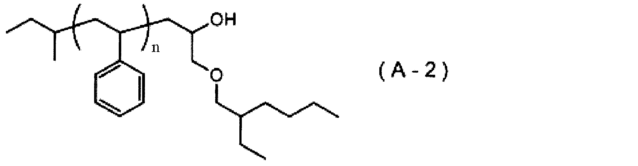
500mLのフラスコ反応容器を減圧乾燥した後、窒素雰囲気下、蒸留脱水処理を行ったTHF120gを注入し、-78℃まで冷却した。その後、このTHFにsec-BuLiの1Nシクロヘキサン溶液を3.10mL(3.00mmol)注入し、その後、重合禁止剤除去のためのシリカゲルによる吸着濾別と蒸留脱水処理とを行ったスチレン16.6mL(0.150mol)を30分かけて滴下注入し、重合系が橙色であることを確認した。この滴下注入の際、重合反応液の内温が-60℃以上にならないように注意した。滴下終了後に30分間熟成した。この後、末端停止剤としてメチルグリシジルエーテル0.27mL(3.00mmol)とメタノール1mLとの混合物を注入し、重合末端の停止反応を行った。この重合反応液を室温まで昇温し、濃縮した後、MIBKで置換した。その後、シュウ酸2質量%水溶液1,000gを注入撹拌し、静置後、下層の水層を取り除いた。この操作を3回繰り返し、Li塩を除去した。その後、超純水1,000gを注入撹拌し、下層の水層を取り除いた。この操作を3回繰り返してシュウ酸を除去した後、溶液を濃縮した後、メタノール500g中に滴下することで重合体を析出させ、ブフナーロートにて固体を回収した。得られた重合体を60℃で減圧乾燥させることで白色の下記式(A-3)で表される重合体14.6gを得た。この重合体(A-3)は、Mwが6,100、Mnが5,600、Mw/Mnが1.09であった。

500mLのフラスコ反応容器を減圧乾燥した後、窒素雰囲気下、蒸留脱水処理を行ったTHF120gを注入し、-78℃まで冷却した。その後、このTHFにsec-ブチルリチウム(sec-BuLi)の1Nシクロヘキサン溶液を3.10mL(3.00mmol)注入し、その後、重合禁止剤除去のためのシリカゲルによる吸着濾別と蒸留脱水処理とを行ったスチレン16.6mL(0.150mol)を30分かけて滴下注入し、重合系が橙色であることを確認した。この滴下注入の際、反応溶液の内温が-60℃以上にならないように注意した。滴下終了後に30分間熟成した。この後、末端停止剤としてプロピレンスルフィド0.24mL(3.00mmol)及びメタノール1mLを注入し重合末端の停止反応を行った。この重合反応液を室温まで昇温し、濃縮した後、MIBKで置換した。その後、2質量%シュウ酸水溶液1,000gを注入撹拌し、静置後、下層の水層を取り除いた。この操作を3回繰り返し、Li塩を除去した。次に、超純水1,000gを注入撹拌し、下層の水層を取り除いた。この操作を3回繰り返してシュウ酸を除去した後、溶液を濃縮してメタノール500g中に滴下することで重合体を析出させ、ブフナーロートにて固体を回収した。得られた重合体を60℃で減圧乾燥させることで白色の重合体(A-4)14.7gを得た。この重合体(A-4)は、Mwが8,600、Mnが6,900、Mw/Mnが1.25であった。

500mLのフラスコ反応容器を減圧乾燥した後、窒素雰囲気下、蒸留脱水処理を行ったTHF120gを注入し、-78℃まで冷却した。その後、このTHFにsec-BuLiの1Nシクロヘキサン溶液を3.10mL(3.00mmol)注入し、その後、重合禁止剤除去のためのシリカゲルによる吸着濾別と蒸留脱水処理とを行ったスチレン16.6mL(0.150mol)を30分かけて滴下注入し、重合系が橙色であることを確認した。この滴下注入の際、重合反応液の内温が-60℃以上にならないように注意した。滴下終了後に30分間熟成した。この後、末端停止剤としてメタノール1mLを注入し重合末端の停止反応を行った。この重合反応液を室温まで昇温し、濃縮した後、MIBKで置換した。その後、2質量%シュウ酸水溶液1,000gを注入撹拌し、静置後、下層の水層を取り除いた。この操作を3回繰り返し、Li塩を除去した。次に、超純水1,000gを注入撹拌し、下層の水層を取り除いた。この操作を3回繰り返してシュウ酸を除去した後、溶液を濃縮してメタノール500g中に滴下することで重合体を析出させ、ブフナーロートにて固体を回収した。この重合体を60℃で減圧乾燥させることで白色の下記式(A-5)で表される重合体14.7gを得た。この重合体(A-5)は、Mwが5,600、Mnが5,300、Mw/Mnが1.06であった。

冷却管、滴下ロート及び温度計を備えた200mL三口フラスコにアニソール85g、スチレン12.1mL(0.105mol)、メタクリル酸メチル1.6mL(0.015mol)、臭化銅(II)0.67g(3.00mmol)及び2-ブロモイソ酪酸メチル0.38mL(3.0mmol)を加え、窒素フロー下、80℃に加熱し、トリス[(2-ジメチルアミノ)エチル]アミン0.81mL(3mmol)を加え、4時間加熱撹拌した。さらに滴下ロートより2-ヒドロキシエチルメタクリレート3.8mL(0.03mol)とアニソール10gとの混合物を約10分かけて滴下した後、4時間熟成させた。重合反応液を室温まで冷却した後、モノエタノールアミン0.18mL(3mmol)とトリエチルアミン5mLとの混合物を加え、6時間撹拌した。得られた重合反応液は、セライト濾過して銅錯体を除去し、1質量%シュウ酸水溶液500gを用いて洗浄を3回繰り返した。有機層を回収して、濃縮し、得られた濃縮物にTHF50gを加えたものをメタノール1,000g中に滴下することで固体を析出させた。得られた固体をブフナーロートにて回収し、メタノール50gを用いて洗浄した。得られた固体を減圧乾燥し、白色の下記式(A-6)で表される重合体11.4gを得た。この重合体(A-6)は、Mwが5,600、Mnが4,600、Mw/Mnが1.22であった。また、1H-NMR分析の結果、スチレンに由来する構造単位、メタクリル酸メチルに由来する構造単位及び2-ヒドロキシエチルメタクリレートに由来する構造単位の含有割合は、それぞれ68モル%、10モル%及び22モル%であり、スチレンに由来する構造単位及びメタクリル酸メチルに由来する構造単位を含むランダム共重合体部と、2-ヒドロキシエチルメタクリレートに由来する構造単位からなるブロックとを有する共重合体であった。

500mLのフラスコ反応容器を減圧乾燥した後、窒素雰囲気下、蒸留脱水処理を行ったTHF120gを注入し、-78℃まで冷却した。次に、このTHFにジフェニルエチレン1.52mL(0.0108mol)、0.5N塩化リチウムのTHF溶液14.3mL(0.0072mol)及びsec-BuLiの1Nシクロヘキサン溶液3.71mL(3.60mmol)を注入し、その後、重合禁止剤除去のためのシリカゲルによる吸着濾別と蒸留脱水処理とを行ったメタクリル酸メチル19.9mL(0.180mol)を30分かけて滴下注入し、重合系が橙色であることを確認した。この滴下注入の際、重合反応液の内温が-60℃以上にならないように注意した。滴下終了後に120分間熟成した。この後、末端停止剤として2-エチルヘキシルグリシジルエーテル0.75mL(3.60mmol)及びメタノール1mLを注入し重合末端の停止反応を行った。この重合反応液を室温まで昇温し、濃縮した後、MIBKで置換した。その後、2質量%シュウ酸水溶液1,000gを注入撹拌し、静置後、下層の水層を取り除いた。この操作を3回繰り返し、Li塩を除去した。その後、超純水1,000gを注入撹拌し、下層の水層を取り除いた。この操作を3回繰り返してシュウ酸を除去した後、得られた溶液を濃縮してメタノール500g中に滴下することで重合体を析出させ、ブフナーロートにて固体を回収した。この重合体を60℃で減圧乾燥させることで白色の下記式(A-7)で表される重合体14.3gを得た。この重合体(A-7)は、Mwが6,000、Mnが5,800、Mw/Mnが1.03であった。
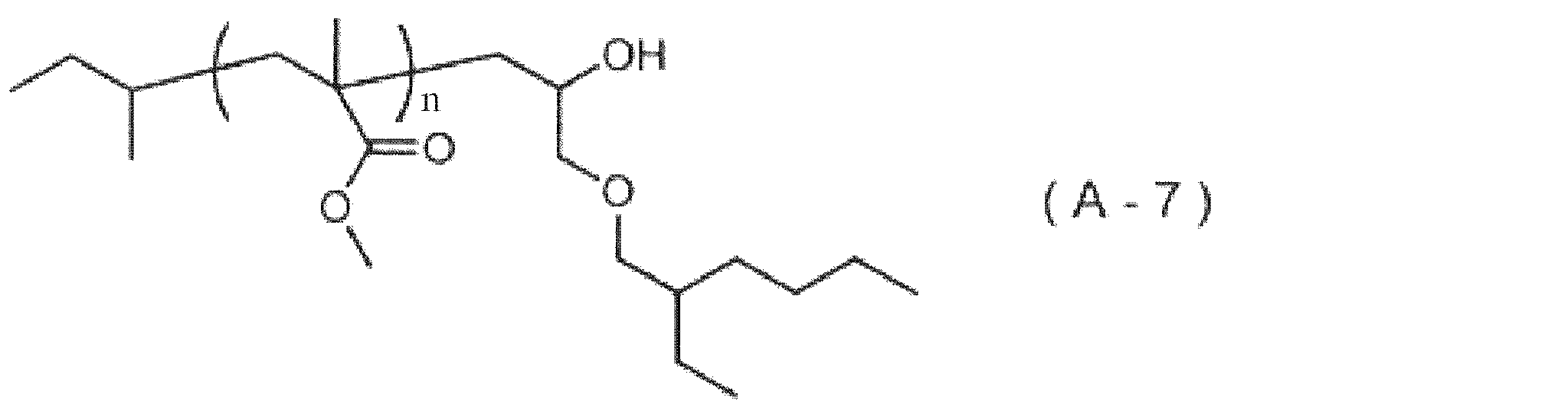
冷却管、滴下ロート及び温度計を備えた200mL三口フラスコにアニソール85g、スチレン6.90mL(0.06mol)、メタクリル酸メチル6.36mL(0.06mol)、臭化銅(II)0.67g(3.00mmol)及び2-ブロモイソ酪酸メチル0.38mL(3.0mmol)を加え、窒素フロー下、80℃に加熱し、トリス[(2-ジメチルアミノ)エチル]アミン0.81mL(3mmol)を加え、8時間加熱撹拌した。重合反応液を室温まで冷却した後、モノエタノールアミン0.18mL(3mmol)とトリエチルアミン5mLとの混合物を加え、6時間撹拌した。得られた重合反応液は、セライト濾過して銅錯体を除去し、1質量%シュウ酸水溶液500gを用いて洗浄を3回繰り返した。有機層を回収して、濃縮し、得られた濃縮物にTHF50gを加えたものをメタノール1,000g中に滴下することで固体を析出させた。得られた固体をブフナーロートにて回収し、メタノール50gを用いて洗浄した。得られた固体を減圧乾燥し、白色の下記式(A-8)で表される重合体11.4gを得た。この重合体(A-8)は、Mwが5,800、Mnが4,600、Mw/Mnが1.26のランダム共重合体であった。また、1H-NMR分析の結果、スチレンに由来する構造単位及びメタクリル酸メチルに由来する構造単位の含有割合は、それぞれ50モル%及び50モル%であった。

500mLのフラスコ反応容器を減圧乾燥した後、窒素雰囲気下、蒸留脱水処理を行ったTHF120gを注入し、-78℃まで冷却した。その後、このTHFにsec-BuLiの1Nシクロヘキサン溶液を2.38mL(2.30mmol)注入し、その後、重合禁止剤除去のためのシリカゲルによる吸着濾別と蒸留脱水処理とを行ったスチレン13.3mL(0.115mol)を30分かけて滴下注入し、重合系が橙色であることを確認した。この滴下注入のとき、反応溶液の内温が-60℃以上にならないように注意した。滴下終了後に30分間熟成した。この後、アリルブロミドを0.20mL(2.30mmol)注入し重合末端の停止反応を行った。この反応溶液を室温まで昇温し、得られた反応溶液を濃縮してMIBKで置換した。その後、シュウ酸2%水溶液1,000gを注入撹拌し、静置後、下層の水層を取り除いた。この操作を3回繰り返し、Li塩を除去した。その後、超純水1,000gを注入撹拌し、下層の水層を取り除いた。この操作を3回繰り返しシュウ酸を除去した後、溶液を濃縮してメタノール500g中に滴下することで重合体を析出させ、ブフナーロートにて固体を回収した。この重合体を60℃で減圧乾燥させることで白色の下記式(A-9)で表される重合体11.4gを得た。この重合体(A-9)は、Mwが5,700、Mnが5,200、Mw/Mnが1.10であった。

500mLのフラスコ反応容器を減圧乾燥した後、窒素雰囲気下、蒸留脱水処理を行ったTHF120gを注入し、-78℃まで冷却した。その後、このTHFにsec-BuLiの1Nシクロヘキサン溶液を2.38mL(2.30mmol)注入し、その後、重合禁止剤除去のためのシリカゲルによる吸着濾別と蒸留脱水処理とを行ったスチレン13.3mL(0.115mol)を30分かけて滴下注入し、重合系が橙色であることを確認した。この滴下注入のとき、反応溶液の内温が-60℃以上にならないように注意した。滴下終了後に30分間熟成した。この後、スチレンオキサイドを0.26mL(2.30mmol)注入し重合末端の停止反応を行った。この反応溶液を室温まで昇温し、得られた反応溶液を濃縮してMIBKで置換した。その後、シュウ酸2%水溶液1,000gを注入撹拌し、静置後、下層の水層を取り除いた。この操作を3回繰り返し、Li塩を除去した。その後、超純水1,000gを注入撹拌し、下層の水層を取り除いた。この操作を3回繰り返しシュウ酸を除去した後、溶液を濃縮してメタノール500g中に滴下することで重合体を析出させ、ブフナーロートにて固体を回収した。この重合体を60℃で減圧乾燥させることで白色の下記式(A-10)で表される重合体11.5gを得た。この重合体(A-10)は、Mwが5,300、Mnが5,000、Mw/Mnが1.06であった。

500mLのフラスコ反応容器を減圧乾燥した後、窒素雰囲気下、蒸留脱水処理を行ったTHF120gを注入し、-78℃まで冷却した。その後、このTHFにsec-BuLiの1Nシクロヘキサン溶液を2.38mL(2.30mmol)注入し、その後、重合禁止剤除去のためのシリカゲルによる吸着濾別と蒸留脱水処理とを行ったスチレン13.3mL(0.115mol)を30分かけて滴下注入し、重合系が橙色であることを確認した。この滴下注入のとき、反応溶液の内温が-60℃以上にならないように注意した。滴下終了後に30分間熟成した。この後、エチレンオキサイドの1mol/L THF溶液を2.40mL(2.40mmol)注入し重合末端の停止反応を行った。この反応溶液を室温まで昇温し、得られた反応溶液を濃縮してMIBKで置換した。その後、シュウ酸2%水溶液1,000gを注入撹拌し、静置後、下層の水層を取り除いた。この操作を3回繰り返し、Li塩を除去した。その後、超純水1,000gを注入撹拌し、下層の水層を取り除いた。この操作を3回繰り返しシュウ酸を除去した後、溶液を濃縮してメタノール500g中に滴下することで重合体を析出させ、ブフナーロートにて固体を回収した。この重合体を60℃で減圧乾燥させることで白色の下記式(A-11)で表される重合体11.6gを得た。この重合体(A-11)は、Mwが5,300、Mnが5,100、Mw/Mnが1.04であった。

500mLのフラスコ反応容器を減圧乾燥した後、窒素雰囲気下、蒸留脱水処理を行ったTHF120gを注入し、-78℃まで冷却した。このTHFにsec-BuLiの1Nシクロヘキサン溶液を2.38mL(2.30mmol)注入し、さらに、重合禁止剤除去のためシリカゲルによる吸着濾別と蒸留脱水処理とを行ったスチレン13.3mL(0.115mol)を30分かけて滴下注入し、重合系が橙色であることを確認した。この滴下注入のとき、反応溶液の内温が-60℃以上にならないように注意した。滴下終了後に30分間熟成した。次に、末端停止剤としての4-クロロメチル-2,2-ジメチル-1,3-ジオキソラン0.32mL(2.30mmol)を注入し重合末端の停止反応を行った。つぎに、1Nの塩酸水溶液を10g加え、60℃で2時間加熱撹拌を行い、加水分解反応を行い、末端基としてジオール構造を有する重合体を得た。この反応溶液を室温まで冷却し、得られた反応溶液を濃縮してMIBKで置換した。その後、シュウ酸2質量%水溶液1,000gを注入撹拌し、静置後、下層の水層を取り除いた。この操作を3回繰り返し、Li塩を除去した。その後、超純水1,000gを注入撹拌し、下層の水層を取り除いた。この操作を3回繰り返しシュウ酸を除去した後、溶液を濃縮してメタノール500g中に滴下することで重合体を析出させ、ブフナーロートにて固体を回収した。この重合体を60℃で減圧乾燥させることで白色の下記式(A-12)で表される重合体11.3gを得た。この重合体(A-12)は、Mwが5,300、Mnが4,900、Mw/Mnが1.08であった。

500mLのフラスコ反応容器を減圧乾燥した後、窒素雰囲気下、蒸留脱水処理を行ったTHF120gを注入し、-78℃まで冷却した。このTHFに1,1-ジフェニルエチレン1.02mL(7.19mmol)及び塩化リチウムの1MTHF溶液9.59mL(4.79mmol)、sec-ブチルリチウム(sec-BuLi)の1Nシクロヘキサン溶液2.47mL(2.40mmol)を注入し、さらに、重合禁止剤除去のためのシリカゲルによる吸着濾別と蒸留脱水処理とを行ったメタクリル酸メチル12.7mL(0.120mol)を30分かけて滴下注入し、重合系が橙色であることを確認した。この滴下注入のとき、反応溶液の内温が-60℃以上にならないように注意した。滴下終了後に120分間熟成した。次にエチレンオキサイドの1mol/Lトルエン溶液2.40mL(2.40mmol)を加え、さらにメタノール1mLを注入し重合末端の停止反応を行った。この反応溶液を室温まで昇温し、得られた反応溶液を濃縮してMIBKで置換した。その後、シュウ酸2質量%水溶液1,000gを注入撹拌し、静置後、下層の水層を取り除いた。この操作を3回繰り返し、Li塩を除去した。その後、超純水1,000gを注入撹拌し、下層の水層を取り除いた。この操作を3回繰り返しシュウ酸を除去した後、溶液を濃縮してメタノール500g中に滴下することで重合体を析出させ、ブフナーロートにて固体を回収した。この重合体を60℃で減圧乾燥させることで白色の下記式(A-13)で表される重合体11.2gを得た。この重合体(A-13)は、Mwが5,200、Mnが5,000、Mw/Mnが1.04であった。
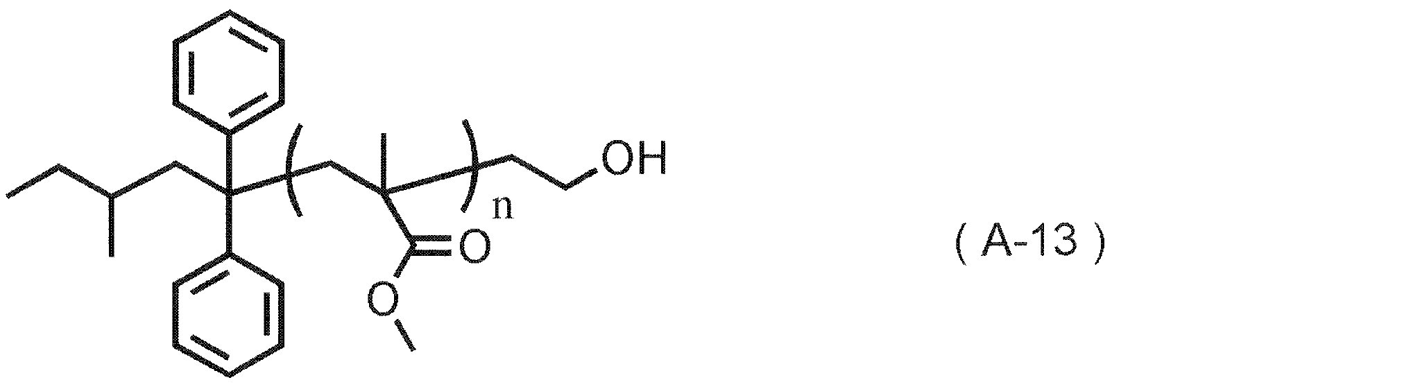
500mLのフラスコ反応容器を減圧乾燥した後、窒素雰囲気下、蒸留脱水処理を行ったTHF200gを注入し、-78℃まで冷却した。その後、このTHFにsec-BuLiの1Nシクロヘキサン溶液を0.30mL(0.27mmol)注入し、その後、重合禁止剤除去のためのシリカゲルによる吸着濾別と蒸留脱水処理とを行ったスチレン17.7mL(0.154mol)を30分かけて滴下注入し、重合系が橙色であることを確認した。この滴下注入の際、重合反応液の内温が-60℃以上にならないように注意した。滴下終了後に30分間熟成し、その後、1,1-ジフェニルエチレン0.11mL(0.00081mol)と、塩化リチウムの0.5NTHF溶液1.08mL(0.0005mol)とを加え、重合系が暗赤色になったことを確認した。さらに、重合禁止剤除去のためのシリカゲルによる吸着濾別と蒸留脱水処理とを行ったメタクリル酸メチル10.0mL(0.094mol)を重合反応液に30分かけて滴下注入し、重合系が薄黄色になったことを確認し、その後120分間反応させた。この後、末端停止剤としてのメタノール1mLを注入し重合末端の停止反応を行った。この重合反応液を室温まで昇温し、濃縮した後、MIBKで置換した。その後、2質量%シュウ酸水溶液1,000gを注入撹拌し、静置後、下層の水層を取り除いた。この操作を3回繰り返し、Li塩を除去した。その後、超純水1,000gを注入撹拌し、下層の水層を取り除いた。この操作を3回繰り返してシュウ酸を除去した後、溶液を濃縮してメタノール500g中に滴下することで重合体を析出させ、ブフナーロートにて固体を回収した。次に、ポリスチレンのホモポリマーを除去するためヘプタン500gを注ぎ、重合体を洗浄し、ポリスチレンホモポリマーをヘプタンへ溶解させた。この操作を4回繰り返し、再度、ブフナーロートにて固体を回収した。得られた重合体を60℃で減圧乾燥させることで白色の下記式(A-a)で表される重合体(A-a)24.1gを得た。この重合体(A-a)は、Mwが79,000、Mnが77,000、Mw/Mnが1.03であった。また、1H-NMR分析の結果、重合体(A-a)は、スチレンに由来する構造単位及びメタクリル酸メチルに由来する構造単位の含有割合が、それぞれ60.0モル%及び40.0モル%のジブロック共重合体であった。

500mLのフラスコ反応容器を減圧乾燥した後、窒素雰囲気下、蒸留脱水処理を行ったTHF200gを注入し、-78℃まで冷却した。次に、このTHFにsec-BuLiの1Nシクロヘキサン溶液を0.30mL(0.27mmol)注入し、その後、重合禁止剤除去のためのシリカゲルによる吸着濾別と蒸留脱水処理とを行ったスチレン20.5mL(0.178mol)を30分かけて滴下注入し、重合系が橙色であることを確認した。この滴下注入の際、重合反応液の内温が-60℃以上にならないように注意した。滴下終了後に30分間熟成し、その後、1,1-ジフェニルエチレン0.11mL(0.00081mol)及び塩化リチウムの0.5NTHF溶液1.08mL(0.0005mol)を加え、重合系が暗赤色になったことを確認した。さらに、重合禁止剤除去のためのシリカゲルによる吸着濾別と蒸留脱水処理とを行ったメタクリル酸メチル9.5mL(0.089mol)を重合反応液に30分かけて滴下注入し、重合系が薄黄色になったことを確認し、その後120分間反応させた。その後、末端停止剤としてのメタノール1mLを注入し重合末端の停止反応を行った。この重合反応液を室温まで昇温し、濃縮した後、MIBKで置換した。その後、2質量%シュウ酸水溶液1,000gを注入撹拌し、静置後、下層の水層を取り除いた。この操作を3回繰り返し、Li塩を除去した。その後、超純水1,000gを注入撹拌し、下層の水層を取り除いた。この操作を3回繰り返してシュウ酸を除去した後、得られた溶液を濃縮してメタノール500g中に滴下することで重合体を析出させ、ブフナーロートにて固体を回収した。次にポリスチレンのホモポリマーを除去するためヘプタン500gを注ぎ、重合体を洗浄し、ポリスチレンホモポリマーをヘプタンへ溶解させた。この作業を4回繰り返し、再度、ブフナーロートにて固体を回収した。この重合体を60℃で減圧乾燥させることで白色の下記式(A-b)で表される重合体(A-b)26.1gを得た。この重合体(A-b)は、Mwが79,000、Mnが76,000、Mw/Mnが1.04であった。また、1H-NMR分析の結果、重合体(A-b)は、スチレンに由来する構造単位及びメタクリル酸メチルに由来する構造単位の含有割合が、それぞれ64.0モル%及び36.0モル%のジブロック共重合体あった。
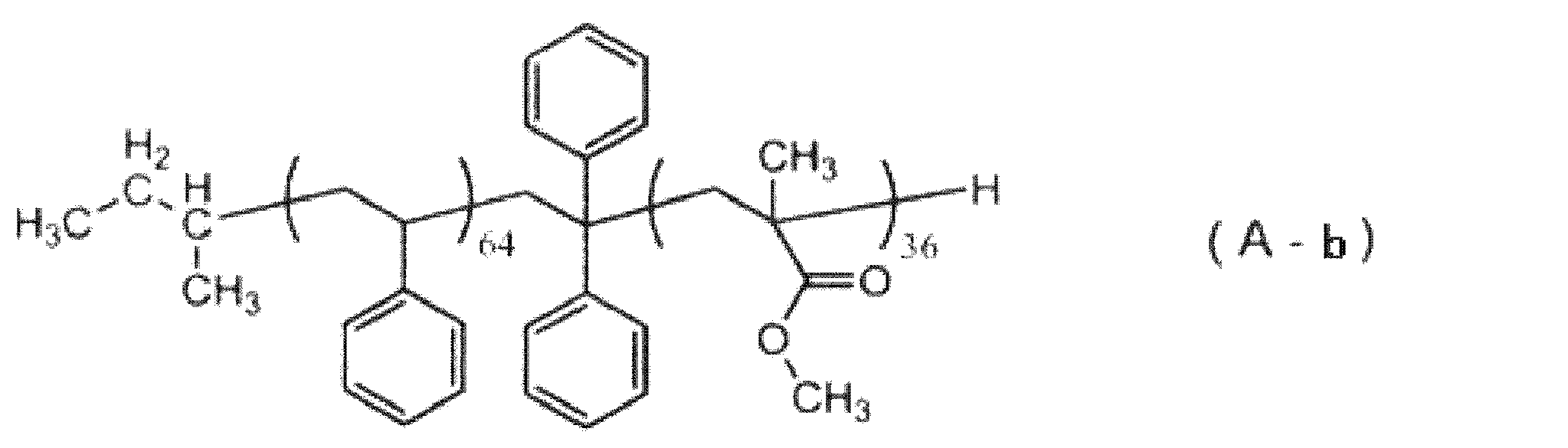
組成物(I)の調製に用いた[A]重合体以外の成分について以下に示す。
B-1:プロピレングリコールモノメチルエーテルアセテート
B-2:γ-ブチロラクトン
C-1:ビス(4-t-ブチルフェニル)ヨードニウムノナフルオロn-ブタンスルホネート(下記式(C-1)で表される化合物)
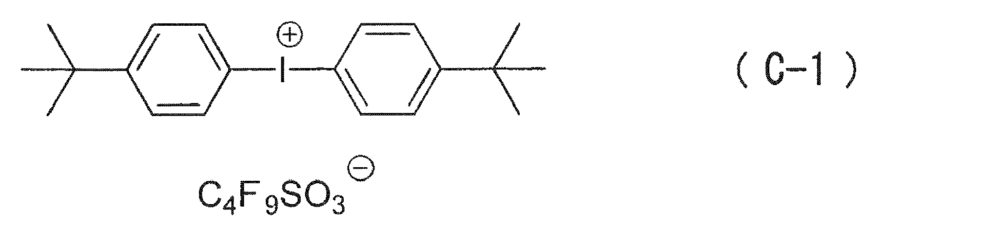
[A]重合体としての(A-1)100質量部、[B]溶媒としての(B-1)9,355質量部及び(B-2)1,040質量部並びに[C]酸発生剤としての(C-1)5質量部を混合し、得られた混合溶液を孔径200nmのメンブランフィルターで濾過して、組成物(S-1)を調製した。
調製例1において、下記表1に示す種類及び含有量の各成分を用いた以外は、調製例1と同様にして、組成物(S-2)~(S-15)並びに(S-a)及び(S-b)を調製した。

Bare-Si基板上に、下層膜形成用組成物(JSR社の「HM710」)を用いて平均厚み85nmの下層膜を形成し、この下層膜上に、SOG組成物(JSR社の「ISX302」)を用いて平均厚み30nmのSOG膜を形成した。得られた基板にポジ型レジスト組成物(JSR社の「AIM5484JN」)を塗布することにより85nmのレジスト膜を形成し、ArF液浸露光し、2.38質量%テトラブチルアンモニウムヒドロキシド水溶液を用いて現像し、レジストパターンを形成した。次に、このレジストパターンをマスクとして、CF4/O2/Airの混合ガスを用いてSOG膜のエッチングを行った。次いで、得られたSOG膜パターンをマスクとして、N2/O2混合ガスにて下層膜のエッチングを行った。さらに下層膜パターンの表層に残ったSOG膜をフッ化水素酸希釈溶液にて剥離を行い、下層膜に、ホールサイズ60nm、ピッチ150nmのホールパターンを形成した。
[実施例1~6及び比較例1~4]
上記形成したホールパターンに対し、以下の手順により、ホールの側面に組成物(I)を塗布し、この組成物(I)とは異なる組成物(II)を用いて、樹脂層を形成し、相分離、及び一部の相の除去することにより、コンタクトホールパターンを形成した。
トラック(東京エレクトロン社の「DSA ACT12」)を用いて、上記形成したホールサイズ60nm、ピッチ150nmのホールパターンへ、下記表2に示す組成物を1,500rpmにてスピンコートし、220℃で60秒間焼成した。次いで、この焼成後の基板をプロピレングリコールモノメチルエーテルアセテート(PGMEA)を用いて4秒間リンスすることにより、未反応物等の除去を行った。組成物(I)の塗布膜の平均厚み(nm)について、上記リンス前及びリンス後にそれぞれ測定した。また、後述の方法により測定した静的接触角を、上記焼成後(リンス前)と、上記リンス後のホールの側面の水との静的接触角として評価した。樹脂層形成工程の直前におけるホールの側面の水との静的接触角Aは、表2中の「リンス後のホールの側面の水との静的接触角」の値である。これらの静的接触角及び塗布膜の平均厚みの測定値を、下記表2に合わせて示す。
上記リンス後の基板に、組成物(II)としての上記調製した組成物(S-a)を1,500rpmにてスピンコートした。この基板を、窒素下、220℃で60秒間、熱アニールすることで相分離させた。樹脂層を形成する組成物が(S-a)の場合、上記式(1)のaで表されるスチレンの単独重合体の成膜状態における水との静的接触角は90°であり、bで表されるメタクリル酸メチルの単独重合体の成膜状態における水との静的接触角は65°である。
上記相分離を行った基板について、172nmの放射線を300mJ/cm2の強度で照射した後、メチルイソブチルケトン(MIBK)/2-プロパノール(IPA)=2/8(質量比)の混合液中に5分間浸漬させて、重合体(A-a)におけるポリ(メタクリル酸メチル)ブロックからなる相を溶解させて除去することにより、コンタクトホールパターンを形成した。
上記形成したコンタクトホールパターンについて、下記方法に従って、評価を行った。評価結果を下記表2に示す。
上記現像後の基板におけるホールパターンについて、走査型電子顕微鏡(日立ハイテクノロジー社の「CG4000」)を用いて高倍率(300K)の画像を取得し、計算ツール(日立ハイテクノロジー社)を用いて周期解析を行うことにより、コンタクトホールパターンの平均直径(nm)及びPlacement Error(x方向及びy方向)を評価した。
上記現像後の基板上に、感光性SOG組成物(JSR社の「DS492Y」)を1,500rpmにてスピンコートした後、80℃で30秒間ソフトベークし、KrF露光機にて200mJ/cm2で照射した後、80℃で120秒間ゾル-ゲル硬化反応させた。このようにしてホールパターンを埋め込んだ上で、底部残渣の平均厚み(nm)を、測長SEMを用いる断面SEM観察により測定した。下記表2における「(*)」は、測定できなかったことを示す。
Bare-Si基板上に、下層膜形成用組成物(JSR社の「HM710」)を用いて平均厚み85nmの下層膜を形成し、この下層膜上に、SOG組成物(JSR社の「ISX302」)を用いて平均厚み30nmのSOG膜を形成した。得られた基板にポジ型レジスト組成物(JSR社の「AIM5484JN」)を塗布することにより85nmのレジスト膜を形成し、ArFを全面露光し、2.38質量%テトラブチルアンモニウムヒドロキシド水溶液を用いてレジスト膜を除去し、CF4/O2/Airの混合ガスを用いてSOG膜のエッチングを行った。さらに下層膜パターンの表層に残ったSOG膜をフッ化水素酸希釈溶液にて剥離を行った。露出した下層膜に対して、上述した(組成物(I)の塗布)の工程に準じ、目的とする樹脂膜を形成した。すなわち、上記下層膜上に組成物を1,500rpmにてスピンコートし、220℃で60秒間焼成した後、この焼成後の基板をプロピレングリコールモノメチルエーテルアセテート(PGMEA)を用いて4秒間リンスすることにより、未反応物等の除去を行った。上記焼成後(リンス前)と、上記リンス後の表面の静的接触角値を、接触角計(協和界面科学社の「Drop Master DM-501」を用いてそれぞれ測定した。
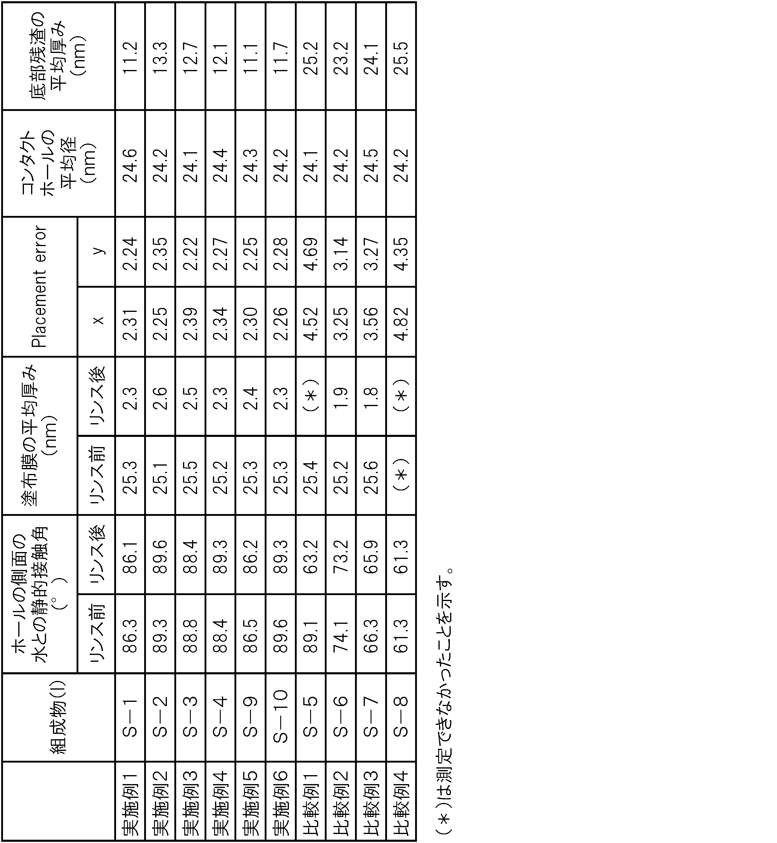
[実施例7及び8並びに比較例5及び6]
実施例1~6において、下記表3に示す組成物(I)を塗布し、この組成物(I)と同一の組成物(II)を用いて、樹脂層を形成し、相分離、及び一部の相の除去を行った以外は、実施例1~6と同様にして、コンタクトホールパターンを形成した(ダブルコートプロセス)。組成物(I)としての(S-a)を塗布し、リンス後のホールの側面の水との静的接触角は88°であり、組成物(I)としての(S-b)を塗布し、リンス後のホールの側面の水との静的接触角は88°であった。比較例では、組成物(I)の塗布は行なわず、組成物(II)による樹脂層の形成、相分離及び一部の相の除去のみを行った。組成物(II)による樹脂層を形成する直前のホールの側面の水との接触角、つまり下層膜そのものの水との接触角は56°であった。得られたコンタクトホールパターンについて、Placement error(x方向及びy方向)、ホールの平均径(nm)及び底部残渣の平均厚み(nm)の測定値を下記表3に合わせて示す。
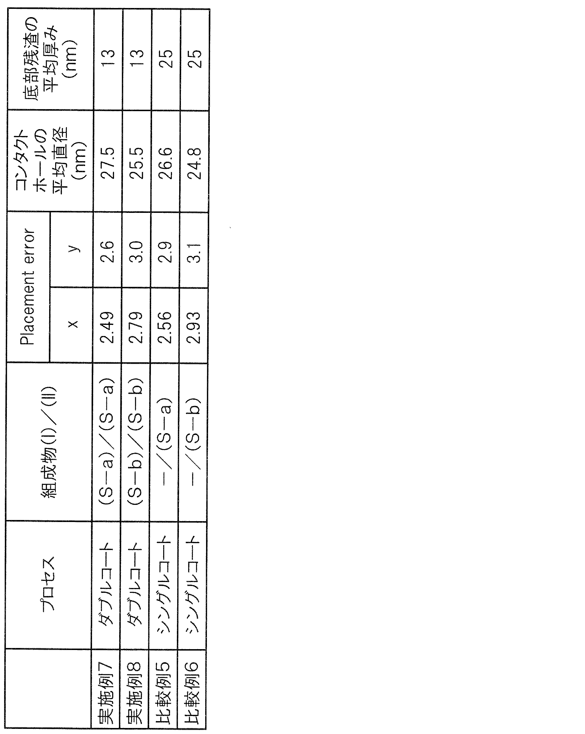
[実施例9~11並びに比較例7及び8]
実施例1~6において、ホールパターンへ、1回目の塗布として、下記表4に示す組成物(I)を塗布し、焼成及びリンスを行った後に、さらに、2回目の塗布として、下記表4に示す組成物(I)を塗布し、1回目の塗布の際と同様にして、焼成及びリンスを行った。1回目の塗布及び2回目の塗布における塗布膜の平均厚み(nm)について、上記リンス前及びリンス後にそれぞれ測定した。
2 ホールパターン
3 組成物(I)の塗布膜
4 樹脂層(I)
4a ブロック(α)相
4b ブロック(β)相
Claims (15)
- 基板の一方の面側にホールパターンを形成する工程、
上記ホールパターンのホールの側面に沿うよう平面視環状に第1組成物を塗布する工程、
上記基板の一方の面側かつ上記第1組成物の塗布を行ったホールの側面の内側に第2組成物により樹脂層を形成する工程、
上記樹脂層を相分離させる工程、及び
上記相分離した樹脂層の一部の相を除去する工程
を備え、
上記第1組成物が、第1重合体と、溶媒とを含有し、
上記第2組成物が、第1構造単位を有する第1ブロック及びこの第1構造単位よりも極性が高い第2構造単位を有する第2ブロックを含む第2重合体と、溶媒とを含有し、
上記樹脂層形成工程の直前におけるホールの側面の水との静的接触角A(°)が、下記式(1)を満たすコンタクトホールパターンの形成方法。

- 上記第1重合体が上記第1構造単位を有する請求項1に記載のコンタクトホールパターンの形成方法。
- 上記第1構造単位が置換又は非置換のスチレンに由来する請求項1又は請求項2に記載のコンタクトホールパターンの形成方法。
- 上記第2構造単位が(メタ)アクリル酸エステルに由来する請求項1、請求項2又は請求項3に記載のコンタクトホールパターンの形成方法。
- 上記第1重合体が、上記第2構造単位、上記第2構造単位とは重合性基に由来する部分以外の構造が異なる第3構造単位又はこれらの組み合わせをさらに有する請求項2、請求項3又は請求項4に記載のコンタクトホールパターンの形成方法。
- 上記第1重合体が、上記第1構造単位及び上記第3構造単位を有する請求項5に記載のコンタクトホールパターンの形成方法。
- 上記第3構造単位が(メタ)アクリル酸ヒドロキシ炭化水素エステル又は(メタ)アクリル酸スルファニル炭化水素エステルに由来する請求項5又は請求項6に記載のコンタクトホールパターンの形成方法。
- 上記第1重合体が、上記第1構造単位及び上記第2構造単位を有する請求項5に記載のコンタクトホールパターンの形成方法。
- 上記第1重合体がランダム共重合体である請求項5から請求項8のいずれか1項に記載のコンタクトホールパターンの形成方法。
- 上記第1重合体が単独重合体である請求項1から請求項4のいずれか1項に記載のコンタクトホールパターンの形成方法。
- 上記第1重合体が、ヒドロキシ基、スルファニル基又はこれらの組み合わせを含む第1基を有する請求項1から請求項10のいずれか1項に記載のコンタクトホールパターンの形成方法。
- 上記第1重合体が、主鎖の少なくとも1つの末端に上記第1基が結合している重合体である請求項11に記載のコンタクトホールパターンの形成方法。
- 上記第1重合体が、上記第1基を含む第3構造単位と、上記第1構造単位とのグラジエントポリマー構造を有する請求項11に記載のコンタクトホールパターンの形成方法。
- 上記塗布工程の後に、上記第1組成物により形成された塗布膜の少なくとも一部を除去する工程を有する請求項1から請求項13のいずれか1項に記載のコンタクトホールパターンの形成方法。
- 基板の一方の面側にホールパターンを形成する工程、
上記ホールパターンのホールの側面に沿うよう平面視環状に第1組成物を塗布する工程、
上記基板の一方の面側かつ上記第1組成物の塗布を行ったホールの側面の内側に第1構造単位を有する第1ブロック及びこの第1構造単位よりも極性が高い第2構造単位を有する第2ブロックを含む第2重合体と、溶媒とを含有する第2組成物により樹脂層を形成する工程、
上記樹脂層を相分離させる工程、並びに
上記相分離した樹脂層の一部の相を除去する工程
を備えるコンタクトホールパターンの形成方法に用いられる組成物であって、
第1重合体と、溶媒とを含有し、
上記樹脂層形成工程の直前におけるホールの側面の水との静的接触角A(°)が、下記式(1)を満たすことを特徴とする組成物。

Priority Applications (3)
| Application Number | Priority Date | Filing Date | Title |
|---|---|---|---|
| KR1020187022102A KR20180112778A (ko) | 2016-02-08 | 2017-02-02 | 콘택트 홀 패턴의 형성 방법 및 조성물 |
| JP2017566910A JP6788198B2 (ja) | 2016-02-08 | 2017-02-02 | コンタクトホールパターンの形成方法及び組成物 |
| US16/940,589 US11335559B2 (en) | 2016-02-08 | 2020-07-28 | Pattern-forming method, and composition |
Applications Claiming Priority (2)
| Application Number | Priority Date | Filing Date | Title |
|---|---|---|---|
| JP2016-022287 | 2016-02-08 | ||
| JP2016022287 | 2016-02-08 |
Related Child Applications (1)
| Application Number | Title | Priority Date | Filing Date |
|---|---|---|---|
| US16/057,017 Continuation-In-Part US20180342387A1 (en) | 2016-02-08 | 2018-08-07 | Pattern-forming method, and composition |
Publications (1)
| Publication Number | Publication Date |
|---|---|
| WO2017138440A1 true WO2017138440A1 (ja) | 2017-08-17 |
Family
ID=59563315
Family Applications (1)
| Application Number | Title | Priority Date | Filing Date |
|---|---|---|---|
| PCT/JP2017/003877 Ceased WO2017138440A1 (ja) | 2016-02-08 | 2017-02-02 | コンタクトホールパターンの形成方法及び組成物 |
Country Status (5)
| Country | Link |
|---|---|
| US (2) | US20180342387A1 (ja) |
| JP (1) | JP6788198B2 (ja) |
| KR (1) | KR20180112778A (ja) |
| TW (1) | TWI711880B (ja) |
| WO (1) | WO2017138440A1 (ja) |
Citations (7)
| Publication number | Priority date | Publication date | Assignee | Title |
|---|---|---|---|---|
| JP2007313568A (ja) * | 2006-05-23 | 2007-12-06 | Kyoto Univ | 微細構造体、パターン媒体、及びそれらの製造方法 |
| JP2008036491A (ja) * | 2006-08-03 | 2008-02-21 | Nippon Telegr & Teleph Corp <Ntt> | パターン形成方法及びモールド |
| JP2008195770A (ja) * | 2007-02-09 | 2008-08-28 | Canon Inc | 液体組成物及びインクジェット用インク |
| JP2010056257A (ja) * | 2008-08-28 | 2010-03-11 | Hitachi Ltd | 微細構造体の製造方法 |
| JP2015170723A (ja) * | 2014-03-06 | 2015-09-28 | Jsr株式会社 | パターン形成方法及び自己組織化組成物 |
| JP2015216180A (ja) * | 2014-05-08 | 2015-12-03 | Jsr株式会社 | パターン形成用組成物及びパターン形成方法 |
| JP2016173415A (ja) * | 2015-03-16 | 2016-09-29 | 株式会社東芝 | パターン形成方法 |
Family Cites Families (12)
| Publication number | Priority date | Publication date | Assignee | Title |
|---|---|---|---|---|
| DE19829172A1 (de) | 1998-06-30 | 2000-01-05 | Univ Konstanz | Verfahren zur Herstellung von Antireflexschichten |
| JP3782357B2 (ja) | 2002-01-18 | 2006-06-07 | 株式会社東芝 | 半導体発光素子の製造方法 |
| US20080038467A1 (en) | 2006-08-11 | 2008-02-14 | Eastman Kodak Company | Nanostructured pattern method of manufacture |
| US8999492B2 (en) * | 2008-02-05 | 2015-04-07 | Micron Technology, Inc. | Method to produce nanometer-sized features with directed assembly of block copolymers |
| US8426313B2 (en) * | 2008-03-21 | 2013-04-23 | Micron Technology, Inc. | Thermal anneal of block copolymer films with top interface constrained to wet both blocks with equal preference |
| US8425982B2 (en) * | 2008-03-21 | 2013-04-23 | Micron Technology, Inc. | Methods of improving long range order in self-assembly of block copolymer films with ionic liquids |
| US8114301B2 (en) * | 2008-05-02 | 2012-02-14 | Micron Technology, Inc. | Graphoepitaxial self-assembly of arrays of downward facing half-cylinders |
| US8114306B2 (en) | 2009-05-22 | 2012-02-14 | International Business Machines Corporation | Method of forming sub-lithographic features using directed self-assembly of polymers |
| US9382444B2 (en) * | 2013-06-24 | 2016-07-05 | Dow Global Technologies Llc | Neutral layer polymers, methods of manufacture thereof and articles comprising the same |
| WO2015180966A2 (en) * | 2014-05-28 | 2015-12-03 | Asml Netherlands B.V. | Methods for providing lithography features on a substrate by self-assembly of block copolymers |
| US20170255096A1 (en) | 2016-03-02 | 2017-09-07 | Jsr Corporation | Pattern-forming method |
| WO2018066716A1 (ja) | 2016-10-07 | 2018-04-12 | Jsr株式会社 | パターン形成方法及び組成物 |
-
2017
- 2017-02-02 WO PCT/JP2017/003877 patent/WO2017138440A1/ja not_active Ceased
- 2017-02-02 KR KR1020187022102A patent/KR20180112778A/ko not_active Ceased
- 2017-02-02 JP JP2017566910A patent/JP6788198B2/ja active Active
- 2017-02-07 TW TW106103865A patent/TWI711880B/zh not_active IP Right Cessation
-
2018
- 2018-08-07 US US16/057,017 patent/US20180342387A1/en not_active Abandoned
-
2020
- 2020-07-28 US US16/940,589 patent/US11335559B2/en active Active
Patent Citations (7)
| Publication number | Priority date | Publication date | Assignee | Title |
|---|---|---|---|---|
| JP2007313568A (ja) * | 2006-05-23 | 2007-12-06 | Kyoto Univ | 微細構造体、パターン媒体、及びそれらの製造方法 |
| JP2008036491A (ja) * | 2006-08-03 | 2008-02-21 | Nippon Telegr & Teleph Corp <Ntt> | パターン形成方法及びモールド |
| JP2008195770A (ja) * | 2007-02-09 | 2008-08-28 | Canon Inc | 液体組成物及びインクジェット用インク |
| JP2010056257A (ja) * | 2008-08-28 | 2010-03-11 | Hitachi Ltd | 微細構造体の製造方法 |
| JP2015170723A (ja) * | 2014-03-06 | 2015-09-28 | Jsr株式会社 | パターン形成方法及び自己組織化組成物 |
| JP2015216180A (ja) * | 2014-05-08 | 2015-12-03 | Jsr株式会社 | パターン形成用組成物及びパターン形成方法 |
| JP2016173415A (ja) * | 2015-03-16 | 2016-09-29 | 株式会社東芝 | パターン形成方法 |
Also Published As
| Publication number | Publication date |
|---|---|
| US20180342387A1 (en) | 2018-11-29 |
| KR20180112778A (ko) | 2018-10-12 |
| TW201800837A (zh) | 2018-01-01 |
| US20200357633A1 (en) | 2020-11-12 |
| US11335559B2 (en) | 2022-05-17 |
| TWI711880B (zh) | 2020-12-01 |
| JP6788198B2 (ja) | 2020-11-25 |
| JPWO2017138440A1 (ja) | 2019-01-10 |
Similar Documents
| Publication | Publication Date | Title |
|---|---|---|
| JP6394042B2 (ja) | パターン形成用組成物及びパターン形成方法 | |
| US9690192B2 (en) | Composition for base, and directed self-assembly lithography method | |
| US9738746B2 (en) | Composition for pattern formation, pattern-forming method, and block copolymer | |
| JP2015170723A (ja) | パターン形成方法及び自己組織化組成物 | |
| JPWO2013073505A1 (ja) | パターン形成用自己組織化組成物及びパターン形成方法 | |
| JP7044976B2 (ja) | パターン形成方法 | |
| KR102393027B1 (ko) | 패턴 형성용 조성물 및 패턴 형성 방법 | |
| JP6554877B2 (ja) | パターン形成方法 | |
| US20170255096A1 (en) | Pattern-forming method | |
| US9557644B2 (en) | Base film-forming composition, and directed self-assembly lithography method | |
| JP6788198B2 (ja) | コンタクトホールパターンの形成方法及び組成物 | |
| US10394121B2 (en) | Pattern-forming method and composition | |
| JP6652721B2 (ja) | パターン形成用組成物及びパターン形成方法 | |
| US20180192524A1 (en) | Forming method of contact hole pattern | |
| JP2015139875A (ja) | パターン形成用自己組織化組成物及びパターン形成方法 | |
| US9847232B1 (en) | Pattern-forming method | |
| JP5966779B2 (ja) | パターン形成方法 |
Legal Events
| Date | Code | Title | Description |
|---|---|---|---|
| 121 | Ep: the epo has been informed by wipo that ep was designated in this application |
Ref document number: 17750164 Country of ref document: EP Kind code of ref document: A1 |
|
| WWE | Wipo information: entry into national phase |
Ref document number: 2017566910 Country of ref document: JP |
|
| ENP | Entry into the national phase |
Ref document number: 20187022102 Country of ref document: KR Kind code of ref document: A |
|
| NENP | Non-entry into the national phase |
Ref country code: DE |
|
| 122 | Ep: pct application non-entry in european phase |
Ref document number: 17750164 Country of ref document: EP Kind code of ref document: A1 |