WO2017138317A1 - 蒸発燃料処理装置および蒸発燃料処理装置における封鎖弁の開弁開始位置学習方法 - Google Patents
蒸発燃料処理装置および蒸発燃料処理装置における封鎖弁の開弁開始位置学習方法 Download PDFInfo
- Publication number
- WO2017138317A1 WO2017138317A1 PCT/JP2017/001647 JP2017001647W WO2017138317A1 WO 2017138317 A1 WO2017138317 A1 WO 2017138317A1 JP 2017001647 W JP2017001647 W JP 2017001647W WO 2017138317 A1 WO2017138317 A1 WO 2017138317A1
- Authority
- WO
- WIPO (PCT)
- Prior art keywords
- valve
- canister
- internal pressure
- fuel
- start position
- Prior art date
- Legal status (The legal status is an assumption and is not a legal conclusion. Google has not performed a legal analysis and makes no representation as to the accuracy of the status listed.)
- Ceased
Links
Images

Classifications
-
- F—MECHANICAL ENGINEERING; LIGHTING; HEATING; WEAPONS; BLASTING
- F02—COMBUSTION ENGINES; HOT-GAS OR COMBUSTION-PRODUCT ENGINE PLANTS
- F02D—CONTROLLING COMBUSTION ENGINES
- F02D41/00—Electrical control of supply of combustible mixture or its constituents
- F02D41/0025—Controlling engines characterised by use of non-liquid fuels, pluralities of fuels, or non-fuel substances added to the combustible mixtures
- F02D41/003—Adding fuel vapours, e.g. drawn from engine fuel reservoir
-
- F—MECHANICAL ENGINEERING; LIGHTING; HEATING; WEAPONS; BLASTING
- F02—COMBUSTION ENGINES; HOT-GAS OR COMBUSTION-PRODUCT ENGINE PLANTS
- F02D—CONTROLLING COMBUSTION ENGINES
- F02D41/00—Electrical control of supply of combustible mixture or its constituents
- F02D41/24—Electrical control of supply of combustible mixture or its constituents characterised by the use of digital means
- F02D41/2406—Electrical control of supply of combustible mixture or its constituents characterised by the use of digital means using essentially read only memories
- F02D41/2425—Particular ways of programming the data
- F02D41/2429—Methods of calibrating or learning
- F02D41/2438—Active learning methods
-
- F—MECHANICAL ENGINEERING; LIGHTING; HEATING; WEAPONS; BLASTING
- F02—COMBUSTION ENGINES; HOT-GAS OR COMBUSTION-PRODUCT ENGINE PLANTS
- F02D—CONTROLLING COMBUSTION ENGINES
- F02D41/00—Electrical control of supply of combustible mixture or its constituents
- F02D41/24—Electrical control of supply of combustible mixture or its constituents characterised by the use of digital means
- F02D41/2406—Electrical control of supply of combustible mixture or its constituents characterised by the use of digital means using essentially read only memories
- F02D41/2425—Particular ways of programming the data
- F02D41/2429—Methods of calibrating or learning
- F02D41/2451—Methods of calibrating or learning characterised by what is learned or calibrated
- F02D41/2464—Characteristics of actuators
-
- F—MECHANICAL ENGINEERING; LIGHTING; HEATING; WEAPONS; BLASTING
- F02—COMBUSTION ENGINES; HOT-GAS OR COMBUSTION-PRODUCT ENGINE PLANTS
- F02M—SUPPLYING COMBUSTION ENGINES IN GENERAL WITH COMBUSTIBLE MIXTURES OR CONSTITUENTS THEREOF
- F02M25/00—Engine-pertinent apparatus for adding non-fuel substances or small quantities of secondary fuel to combustion-air, main fuel or fuel-air mixture
- F02M25/08—Engine-pertinent apparatus for adding non-fuel substances or small quantities of secondary fuel to combustion-air, main fuel or fuel-air mixture adding fuel vapours drawn from engine fuel reservoir
-
- F—MECHANICAL ENGINEERING; LIGHTING; HEATING; WEAPONS; BLASTING
- F02—COMBUSTION ENGINES; HOT-GAS OR COMBUSTION-PRODUCT ENGINE PLANTS
- F02M—SUPPLYING COMBUSTION ENGINES IN GENERAL WITH COMBUSTIBLE MIXTURES OR CONSTITUENTS THEREOF
- F02M25/00—Engine-pertinent apparatus for adding non-fuel substances or small quantities of secondary fuel to combustion-air, main fuel or fuel-air mixture
- F02M25/08—Engine-pertinent apparatus for adding non-fuel substances or small quantities of secondary fuel to combustion-air, main fuel or fuel-air mixture adding fuel vapours drawn from engine fuel reservoir
- F02M25/0836—Arrangement of valves controlling the admission of fuel vapour to an engine, e.g. valve being disposed between fuel tank or absorption canister and intake manifold
-
- F—MECHANICAL ENGINEERING; LIGHTING; HEATING; WEAPONS; BLASTING
- F02—COMBUSTION ENGINES; HOT-GAS OR COMBUSTION-PRODUCT ENGINE PLANTS
- F02M—SUPPLYING COMBUSTION ENGINES IN GENERAL WITH COMBUSTIBLE MIXTURES OR CONSTITUENTS THEREOF
- F02M25/00—Engine-pertinent apparatus for adding non-fuel substances or small quantities of secondary fuel to combustion-air, main fuel or fuel-air mixture
- F02M25/08—Engine-pertinent apparatus for adding non-fuel substances or small quantities of secondary fuel to combustion-air, main fuel or fuel-air mixture adding fuel vapours drawn from engine fuel reservoir
- F02M25/089—Layout of the fuel vapour installation
-
- B—PERFORMING OPERATIONS; TRANSPORTING
- B60—VEHICLES IN GENERAL
- B60K—ARRANGEMENT OR MOUNTING OF PROPULSION UNITS OR OF TRANSMISSIONS IN VEHICLES; ARRANGEMENT OR MOUNTING OF PLURAL DIVERSE PRIME-MOVERS IN VEHICLES; AUXILIARY DRIVES FOR VEHICLES; INSTRUMENTATION OR DASHBOARDS FOR VEHICLES; ARRANGEMENTS IN CONNECTION WITH COOLING, AIR INTAKE, GAS EXHAUST OR FUEL SUPPLY OF PROPULSION UNITS IN VEHICLES
- B60K15/00—Arrangement in connection with fuel supply of combustion engines or other fuel consuming energy converters, e.g. fuel cells; Mounting or construction of fuel tanks
- B60K15/03—Fuel tanks
- B60K15/035—Fuel tanks characterised by venting means
- B60K15/03504—Fuel tanks characterised by venting means adapted to avoid loss of fuel or fuel vapour, e.g. with vapour recovery systems
- B60K2015/03514—Fuel tanks characterised by venting means adapted to avoid loss of fuel or fuel vapour, e.g. with vapour recovery systems with vapor recovery means
-
- F—MECHANICAL ENGINEERING; LIGHTING; HEATING; WEAPONS; BLASTING
- F02—COMBUSTION ENGINES; HOT-GAS OR COMBUSTION-PRODUCT ENGINE PLANTS
- F02D—CONTROLLING COMBUSTION ENGINES
- F02D19/00—Controlling engines characterised by their use of non-liquid fuels, pluralities of fuels, or non-fuel substances added to the combustible mixtures
- F02D19/06—Controlling engines characterised by their use of non-liquid fuels, pluralities of fuels, or non-fuel substances added to the combustible mixtures peculiar to engines working with pluralities of fuels, e.g. alternatively with light and heavy fuel oil, other than engines indifferent to the fuel consumed
- F02D19/0602—Control of components of the fuel supply system
- F02D19/0613—Switch-over from one fuel to another
- F02D19/0621—Purging of the fuel system
-
- F—MECHANICAL ENGINEERING; LIGHTING; HEATING; WEAPONS; BLASTING
- F02—COMBUSTION ENGINES; HOT-GAS OR COMBUSTION-PRODUCT ENGINE PLANTS
- F02D—CONTROLLING COMBUSTION ENGINES
- F02D41/00—Electrical control of supply of combustible mixture or its constituents
- F02D41/0025—Controlling engines characterised by use of non-liquid fuels, pluralities of fuels, or non-fuel substances added to the combustible mixtures
- F02D41/003—Adding fuel vapours, e.g. drawn from engine fuel reservoir
- F02D41/0032—Controlling the purging of the canister as a function of the engine operating conditions
-
- F—MECHANICAL ENGINEERING; LIGHTING; HEATING; WEAPONS; BLASTING
- F02—COMBUSTION ENGINES; HOT-GAS OR COMBUSTION-PRODUCT ENGINE PLANTS
- F02D—CONTROLLING COMBUSTION ENGINES
- F02D41/00—Electrical control of supply of combustible mixture or its constituents
- F02D41/0025—Controlling engines characterised by use of non-liquid fuels, pluralities of fuels, or non-fuel substances added to the combustible mixtures
- F02D41/003—Adding fuel vapours, e.g. drawn from engine fuel reservoir
- F02D41/0032—Controlling the purging of the canister as a function of the engine operating conditions
- F02D41/0035—Controlling the purging of the canister as a function of the engine operating conditions to achieve a special effect, e.g. to warm up the catalyst
- F02D41/0037—Controlling the purging of the canister as a function of the engine operating conditions to achieve a special effect, e.g. to warm up the catalyst for diagnosing the engine
-
- F—MECHANICAL ENGINEERING; LIGHTING; HEATING; WEAPONS; BLASTING
- F02—COMBUSTION ENGINES; HOT-GAS OR COMBUSTION-PRODUCT ENGINE PLANTS
- F02D—CONTROLLING COMBUSTION ENGINES
- F02D41/00—Electrical control of supply of combustible mixture or its constituents
- F02D41/0025—Controlling engines characterised by use of non-liquid fuels, pluralities of fuels, or non-fuel substances added to the combustible mixtures
- F02D41/003—Adding fuel vapours, e.g. drawn from engine fuel reservoir
- F02D41/0032—Controlling the purging of the canister as a function of the engine operating conditions
- F02D41/004—Control of the valve or purge actuator, e.g. duty cycle, closed loop control of position
Definitions
- the present disclosure relates to an evaporative fuel processing apparatus including a block valve installed in a vapor passage connecting a fuel tank and a canister, and a valve opening start position learning method of the block valve.
- the valve opening start position of the block valve is learned based on the change in the internal pressure of the fuel tank when the block valve driven by the stepping motor and the axial distance between the valve body and the valve seat of the block valve are changed.
- An evaporative fuel processing device including a control device is known (for example, see Patent Document 1).
- the control device of the fuel vapor processing apparatus moves the valve body in the valve opening direction from the valve closing limit position of the block valve by a predetermined stroke, and the internal pressure of the fuel tank is set to the previously detected value. On the other hand, it is determined whether or not it has decreased by a predetermined value or more.
- the control device determines that the internal pressure of the fuel tank has decreased by a predetermined value or more with respect to the previous detection value, the control device regards that the block valve has started to open, and based on the total stroke amount from the valve closing limit position.
- the learning value of the valve opening start position is calculated. Further, the control device determines whether or not the increase in the internal pressure of the fuel tank is within the allowable range, and the increase in the internal pressure of the fuel tank is outside the allowable range during or before learning the valve opening start position of the block valve. If it is determined that the learning is, the learning of the valve opening start position is interrupted or prohibited.
- the detection value of the sensor that detects the internal pressure of the fuel tank changes not only according to the fuel evaporation state in the fuel tank but also depending on the behavior of the vehicle equipped with the evaporated fuel processing device, that is, the behavior of the fuel in the fuel tank. . Therefore, even if learning of the valve opening start position of the blocking valve is once started, learning of the valve opening start position is prohibited if the internal pressure (detected value) of the fuel tank changes due to a change in fuel behavior as the vehicle travels. Or it may be interrupted. Therefore, in the conventional fuel vapor processing apparatus, it is difficult to accurately learn the valve opening start position of the blocking valve while the vehicle is running, and there is still room for improvement in terms of securing a learning opportunity.
- the main object of the present disclosure is to increase learning opportunities while ensuring good learning accuracy of the opening start position of the blocking valve.
- An evaporative fuel processing apparatus of the present disclosure is provided in a vapor passage that connects a fuel tank and a canister, and has a block valve having a valve body that moves forward and backward in an axial direction with respect to a valve seat, and communication between the canister and the atmosphere.
- an evaporative fuel processing apparatus including a shut-off valve that can be shut off, a tank internal pressure sensor that detects an internal pressure of the fuel tank, and a canister internal pressure sensor that detects an internal pressure of the canister, a control that controls the block valve and the shut-off valve
- the fuel tank is configured to change an axial distance between the valve body and the valve seat in a state where communication between the canister and the atmosphere is blocked by the shut-off valve, and according to the change in the axial distance.
- a control device that learns a valve opening start position of the blocking valve based on an internal pressure change of the canister.
- the sealing valve is opened by a change in the axial distance between the valve body and the valve seat in a state where the internal pressure of the fuel tank is positive and the communication between the canister and the atmosphere is blocked by the shut-off valve.
- the valve When the valve is operated, the internal pressure of the fuel tank decreases and the internal pressure of the canister increases.
- the internal pressure of the fuel tank is negative and the communication between the canister and the atmosphere is blocked by the shut-off valve, the internal pressure of the fuel tank increases when the block valve opens due to the change in the axial distance. The internal pressure of the canister decreases.
- the influence of the behavior of the fuel in the fuel tank on the detected value of the canister internal pressure sensor is very small. Therefore, by changing the axial distance in a state where the communication between the canister and the atmosphere is cut off, and learning the valve opening start position of the block valve based on the internal pressure change of the fuel tank and the canister, the fuel in the fuel tank Changes in fuel behavior in the fuel tank, such as when a vehicle equipped with an evaporative fuel treatment device is running, while suppressing mislearning of the valve opening start position due to changes in the detected value of the tank internal pressure sensor in response to changes in the behavior of the vehicle It is possible to allow learning of the valve opening start position when the occurrence of As a result, it is possible to increase learning opportunities while ensuring good learning accuracy of the opening start position of the blocking valve.
- control device has an absolute value of an internal pressure change amount of the fuel tank according to a change in the axial distance that is equal to or greater than a predetermined tank internal pressure threshold value, and the canister according to the change in the axial distance.
- the command value for the axial distance may be stored as a learned value for the valve opening start position.
- control device determines the valve opening start position when the internal pressure of the fuel tank is equal to or lower than a first threshold value lower than the standard atmospheric pressure or equal to or higher than a second threshold value higher than the standard atmospheric pressure. Learning may be performed.
- a valve opening start position learning method for a sealing valve in an evaporative fuel processing apparatus is provided in a vapor passage that connects a fuel tank and a canister and has a valve body that moves forward and backward in an axial direction with respect to a valve seat.
- a shutoff valve in an evaporative fuel processing apparatus including: a shutoff valve capable of shutting off communication between the canister and the atmosphere; a tank internal pressure sensor that detects an internal pressure of the fuel tank; and a canister internal pressure sensor that detects an internal pressure of the canister.
- valve opening start position learning method of the present invention wherein the axial distance between the valve body and the valve seat is changed in a state where the communication between the canister and the atmosphere is blocked by the shut-off valve, and the change in the axial distance Learning a valve opening start position of the blocking valve based on changes in internal pressure of the fuel tank and the canister according to the conditions.
- FIG. 1 is a schematic configuration diagram illustrating an evaporated fuel processing apparatus 20 according to the present disclosure.
- evaporative fuel generated in a fuel tank 10 storing fuel supplied to a combustion chamber 2 of an engine (internal combustion engine) 1 mounted on a vehicle (not shown) leaks to the outside. It is for suppressing the above.
- the air purified by the air cleaner 3 is sucked into the combustion chambers 2 via the intake pipe 4, the throttle valve 5, an intake valve (not shown), and the like.
- the fuel is injected from the fuel injection valve 6 in 4p or in each combustion chamber 2.
- the engine 1 is controlled by an electronic control unit (hereinafter referred to as “ECU”) 8 which is a microcomputer including a CPU (not shown).
- ECU electronice control unit
- the vehicle on which the engine 1 is mounted may have only the engine 1 as a power source that outputs driving power, and includes a hybrid that includes an electric motor that can output driving power in addition to the engine 1. It may be a vehicle.
- the fuel tank 10 regulates a fuel inlet pipe 11 for supplying fuel into the fuel tank 10 through a fuel filler port of a vehicle (not shown), a vent line 12, and a reverse flow of fuel from the fuel tank 10 to the fuel filler port.
- a check valve 13 a fuel sender gauge 14 for detecting the level of fuel in the fuel tank 10 using a float, a tank internal pressure sensor 15 for detecting the internal pressure Ptk of the fuel tank 10, and the like.
- Each of the fuel sender gauge 14 and the tank internal pressure sensor 15 transmits a signal indicating the detected value to the ECU 8.
- a fuel passage 16 is connected to the upper portion of the fuel tank 10, and a fuel pump module 17 controlled by the ECU 8 and connected to the fuel passage 16 is disposed in the fuel tank 10. The fuel injected by the fuel pump module 17 is supplied to the fuel injection valve 6 of the engine 1 through the fuel passage 16.
- the evaporative fuel processing device 20 is installed in the middle of a canister 22, a vapor passage 24 connecting the fuel tank 10 and the canister 22, a purge passage 26, an atmospheric passage 28, and a vapor passage 24.
- Block valve 30 The canister 22 has activated carbon as an adsorbent disposed therein, and adsorbs the evaporated fuel in the fuel tank 10 with the adsorbent.
- One end portion (upstream end portion) of the vapor passage 24 is connected to the fuel tank 10 so as to communicate with the gas layer portion in the fuel tank 10, and the other end portion (downstream end portion) of the vapor passage 24 is
- the canister 22 is connected to communicate with the inside of the canister 22.
- One end (upstream end) of the purge passage 26 is connected to the canister 22 so as to communicate with the inside of the canister 22, and the other end (downstream end) of the purge passage 26 is connected to the engine 1.
- the intake pipe 4 is connected downstream of the throttle valve 5.
- a purge valve 27 that can shut off the purge passage 26 is provided in the middle of the purge passage 26.
- the purge valve 27 is an on-off valve controlled by the ECU 8, and is normally maintained in a closed state.
- one end of the atmospheric passage 28 is connected to the canister 22 via a key-off pump module 40 as a diagnostic part used for failure diagnosis of the evaporated fuel processing apparatus 20.
- the key-off pump module 40 includes a switching valve (shutoff valve) 41 and a vacuum pump (decompression pump) 45 that are open / close valves controlled by the ECU 8, and a canister internal pressure sensor 47 that detects the internal pressure Pc of the canister 22 and transmits it to the ECU 8.
- the switching valve 41 allows communication between the inside of the canister 22 and the atmospheric passage 28 when the valve is open, and blocks communication between the two when the valve is closed.
- the vacuum pump 45 can depressurize (depressurize) the inside of the canister 22 with the switching valve 41 closed.
- An air filter 29 is installed in the middle of the atmospheric passage 28, and the other end of the atmospheric passage 28 is open to the atmosphere.
- the block valve 30 is a flow rate adjustment valve controlled by the ECU 8, blocks the vapor passage 24 when the valve is closed, blocks communication between the fuel tank 10 and the canister 22, and flows through the vapor passage 24 when the valve is open.
- the flow rate of the gas to be adjusted is adjusted.
- the blocking valve 30 includes a casing 31, a valve seat 32 formed in the casing 31, a valve body 33 disposed in the casing 31 so as to be movable in the axial direction, and a valve guide (not shown) disposed in the casing 31.
- a stepping motor 34 connected to the valve body 33 via the. The stepping motor 34 is controlled by the ECU 8 and moves the valve body 33 forward and backward relative to the valve seat 32 in the axial direction.
- valve body 33 With the operation of the stepping motor 34, the valve body 33 approaches the valve seat 32, and a sealing member (not shown) of the valve body 33 comes into contact with the valve seat 32, thereby closing the closing valve 30. Further, the valve element 33 is separated from the valve seat 32 in accordance with the operation of the stepping motor 34, and a sealing member (not shown) of the valve element 33 is separated from the valve seat 32, so that the blocking valve 30 is opened.
- the blocking valve 30 is maintained in the closed state, and the fuel vapor in the fuel tank 10 flows into the canister 22. There is no. Further, while the vehicle is parked, the purge passage 26 is maintained in the shut-off state by closing the purge valve 27, and the canister 22 is in communication with the atmospheric passage 28 by opening the switching valve 41. Maintained. Further, in the fuel vapor processing apparatus 20, the ECU 8 diagnoses whether there is a leak in the vapor passage 24 or the purge passage 26 at the time of key-off of the vehicle with the ignition switch (start switch) turned off (when the operation of the engine 1 is stopped). .
- the ECU 8 opens the purge valve 27 in a state where the interior of the canister 22 is in communication with the atmospheric passage 28. As a result, the intake negative pressure of the engine 1 (intake pipe 4) is supplied into the canister 22 via the purge passage 26, so that air flows into the canister 22 from the atmospheric passage 28.
- the ECU 8 opens the closing valve 30 to execute the pressure relief of the fuel tank 10.
- the gas (evaporated fuel) in the fuel tank 10 flows into the canister 22 through the vapor passage 24 (blocking valve 30).
- the adsorbent of the canister 22 is purged by air or the like flowing into the canister 22, and the evaporated fuel separated from the adsorbent is guided to the intake pipe 4 of the engine 1 together with air and burns in the combustion chamber 2. Be made.
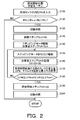
- FIG. 2 is a flowchart showing an example of a valve opening start position learning routine executed by the ECU 8.
- the valve opening start position learning routine of FIG. 2 is executed when a predetermined timing such as when the vehicle stops is reached.
- the ECU 8 CPU not shown
- the ECU 8 inputs the internal pressure Ptk of the fuel tank 10 detected by the tank internal pressure sensor 15 (step S100).
- the ECU 8 determines whether or not the internal pressure Ptk of the fuel tank 10 is equal to or lower than a first threshold value Pa that is lower than the standard atmospheric pressure, or equal to or higher than a second threshold value Pb that is higher than the standard atmospheric pressure (step S110).
- the ECU 8 considers that the execution condition for learning the valve opening start position is not satisfied, and this End the routine.
- step S110 when it is determined in step S110 that the internal pressure Ptk is equal to or lower than the first threshold value Pa or equal to or higher than the second threshold value Pb, the ECU 8 considers that the execution condition for learning the valve opening start position is satisfied. Then, the switching valve 41 of the key-off pump module 40 is closed (step S120). As a result, the communication between the inside of the canister 22 and the atmosphere (atmosphere passage 28) is blocked, so that the internal pressure Pc of the canister 22 is not affected by the atmosphere, and the state of the block valve 30, that is, the actual state of the fuel tank 10 It changes according to the internal pressure Ptk. At this time, the purge valve 27 is maintained in a closed state.
- the ECU 8 sets a predetermined limit valve closing step S0 to an initial step Sint as an initial command value for the stepping motor 34 of the block valve 30 (step S130).
- the valve body 33 is moved from a state in which the closing valve 30 is completely closed to a state immediately before the valve member 33 is in contact with the valve seat 32 until the valve is opened. It is predetermined as a step amount of the stepping motor 34 (a command value for an axial distance between the valve element 33 and the valve seat 32).
- the ECU 8 controls the stepping motor 34 so that the rotor of the stepping motor 34 rotates (high-speed rotation) by the set initial step Sint, and the initial step Sint is used for the control of the stepping motor 34. It is memorize
- the ECU 8 controls the stepping motor 34 so that the rotor of the stepping motor 34 rotates by a predetermined learning step SL (for example, several steps) (step S150). Further, the ECU 8 stores the value obtained by adding the learning step SL to the post-addition step SA at that time in the RAM as a new post-addition step SA (step S160). Next, the ECU 8 determines a predetermined value after the rotor has rotated by the learning step SL based on the internal pressure Ptk of the fuel tank 10 detected by the tank internal pressure sensor 15 and the internal pressure Pc of the canister 22 detected by the canister internal pressure sensor 47.
- a predetermined learning step SL for example, several steps
- a change amount (tank pressure change amount) ⁇ Ptk of the internal pressure Ptk of the fuel tank 10 and a change amount (canister pressure change amount) ⁇ Pc of the canister 22 until the time (for example, several hundred mSec) elapses are acquired.
- the ECU 8 determines that the absolute value of the tank pressure change amount ⁇ Ptk is equal to or greater than a threshold value (tank internal pressure threshold value) ⁇ Ptkref which is a predetermined positive value, and the absolute value of the canister pressure change amount ⁇ Pc is a predetermined positive value. It is determined whether or not the value is a threshold value (canister internal pressure threshold value) ⁇ Pcref (positive value) or more (step S180).
- step S180 when it is determined in step S180 that the absolute value of the tank pressure change amount ⁇ Ptk is equal to or greater than the threshold value ⁇ Ptkref and the absolute value of the canister pressure change amount ⁇ Pc is not equal to or greater than the predetermined threshold value ⁇ Pcref, the ECU 8
- the internal pressure Ptk of the fuel tank 10 and the internal pressure Pc of the canister 22 are not substantially changed, and it is assumed that the closing valve 30 has not been opened, and the processes after step S150 are executed again.
- step S180 if it is determined in step S180 that the absolute value of the tank pressure change amount ⁇ Ptk is equal to or greater than the threshold value ⁇ Ptkref and the absolute value of the canister pressure change amount ⁇ Pc is equal to or greater than a predetermined threshold value ⁇ Pcref, the ECU 8 It is considered that the internal pressure Ptk of the fuel tank 10 and the internal pressure Pc of the canister 22 have substantially changed due to the opening of the shutoff valve 30, and the post-addition step SA stored in the RAM at that time is the valve opening start position. Is stored in the RAM as the valve opening start step SS which is the learned value (step S190). Then, the ECU 8 ends the routine after opening the switching valve 41 (step S200).
- the ECU 8 serving as the control unit for the fuel vapor processing apparatus 20 learns the axial distance between the valve body 33 and the valve seat 32 in a state where the communication between the canister 22 and the atmosphere is blocked by the switching valve 41. While changing the distance corresponding to step SL, the valve opening start position of the blocking valve 30 is learned based on changes in the internal pressure of the fuel tank 10 and the canister 22 (steps S120 to S190). That is, the ECU 8 considers the change in the internal pressure Pc of the canister 22 that is not substantially affected by the change in the behavior of the fuel in the fuel tank 10 in addition to the change in the internal pressure Ptk of the fuel tank 10. 30 learning of the valve opening start position is executed.
- the evaporative fuel processing device 20 can increase learning opportunities while ensuring good learning accuracy of the valve opening start position of the blocking valve 30.
- the evaporated fuel processing apparatus 20 of the present disclosure includes the valve body 33 that is installed in the vapor passage 24 that connects the fuel tank 10 and the canister 22 and that moves forward and backward in the axial direction with respect to the valve seat 32.
- the ECU 8 as the control device changes the axial distance between the valve body 33 and the valve seat 32 in a state where the communication between the canister 22 and the atmosphere is blocked by the switching valve 41, and responds to the change in the axial distance.
- the valve opening start position of the block valve 30 is learned (steps S120 to S190). As a result, it is possible to increase learning opportunities while ensuring good learning accuracy of the valve opening start position of the blocking valve 30.
- the invention of the present disclosure can be used in the manufacturing industry of a fuel vapor processing apparatus.
Landscapes
- Engineering & Computer Science (AREA)
- Chemical & Material Sciences (AREA)
- Combustion & Propulsion (AREA)
- Mechanical Engineering (AREA)
- General Engineering & Computer Science (AREA)
- Supplying Secondary Fuel Or The Like To Fuel, Air Or Fuel-Air Mixtures (AREA)
Abstract
Description
Claims (4)
- 燃料タンクとキャニスタとを結ぶベーパ通路に設置されると共に弁座に対して軸方向に進退移動する弁体を有する封鎖弁と、前記キャニスタと大気との連通を遮断可能な遮断弁と、前記燃料タンクの内圧を検出するタンク内圧センサと、前記キャニスタの内圧を検出するキャニスタ内圧センサとを含む蒸発燃料処理装置において、
前記封鎖弁および前記遮断弁を制御する制御装置であって、前記遮断弁により前記キャニスタと大気との連通が遮断された状態で前記弁体と前記弁座との軸方向距離を変化させ、前記軸方向距離の変化に応じた前記燃料タンクおよび前記キャニスタの内圧変化に基づいて前記封鎖弁の開弁開始位置を学習する制御装置を備える蒸発燃料処理装置。 - 請求項1に記載の蒸発燃料処理装置において、
前記制御装置は、前記軸方向距離の変化に応じた前記燃料タンクの内圧変化量の絶対値が予め定められたタンク内圧閾値以上であり、かつ前記軸方向距離の変化に応じた前記キャニスタの内圧変化量の絶対値が予め定められたキャニスタ内圧閾値以上である場合、前記軸方向距離の指令値を前記開弁開始位置の学習値として記憶する蒸発燃料処理装置。 - 請求項1または2に記載の蒸発燃料処理装置において、
前記制御装置は、前記燃料タンクの前記内圧が標準大気圧よりも低い第1閾値以下であるか、あるいは前記標準大気圧よりも高い第2閾値以上である場合、前記開弁開始位置の学習を実行する蒸発燃料処理装置。 - 燃料タンクとキャニスタとを結ぶベーパ通路に設置されると共に弁座に対して軸方向に進退移動する弁体を有する封鎖弁と、前記キャニスタと大気との連通を遮断可能な遮断弁と、前記燃料タンクの内圧を検出するタンク内圧センサと、前記キャニスタの内圧を検出するキャニスタ内圧センサとを含む蒸発燃料処理装置における封鎖弁の開弁開始位置学習方法であって、
前記遮断弁により前記キャニスタと大気との連通が遮断された状態で前記弁体と前記弁座との軸方向距離を変化させ、前記軸方向距離の変化に応じた前記燃料タンクおよび前記キャニスタの内圧変化に基づいて前記封鎖弁の開弁開始位置を学習するステップを含む蒸発燃料処理装置における封鎖弁の開弁開始位置学習方法。
Priority Applications (4)
| Application Number | Priority Date | Filing Date | Title |
|---|---|---|---|
| CN201780010844.6A CN108884787B (zh) | 2016-02-10 | 2017-01-19 | 蒸发燃料处理装置和蒸发燃料处理装置中的闭锁阀的开阀开始位置学习方法 |
| KR1020187025692A KR102021715B1 (ko) | 2016-02-10 | 2017-01-19 | 증발 연료 처리 장치 및 증발 연료 처리 장치에 있어서의 봉쇄 밸브의 밸브 개방 개시 위치 학습 방법 |
| US16/076,856 US10718280B2 (en) | 2016-02-10 | 2017-01-19 | Vaporized fuel treatment device and learning method of valve opening start position of sealing valve in vaporized fuel treatment device |
| DE112017000742.9T DE112017000742B4 (de) | 2016-02-10 | 2017-01-19 | Kraftstoffdampfbehandlungsvorrichtung und Lernverfahren einer Ventilöffnungsstartposition eines Dichtungsventils in einer Kraftstoffdampfbehandlungsvorrichtung |
Applications Claiming Priority (2)
| Application Number | Priority Date | Filing Date | Title |
|---|---|---|---|
| JP2016023946A JP6588357B2 (ja) | 2016-02-10 | 2016-02-10 | 蒸発燃料処理装置 |
| JP2016-023946 | 2016-02-10 |
Publications (1)
| Publication Number | Publication Date |
|---|---|
| WO2017138317A1 true WO2017138317A1 (ja) | 2017-08-17 |
Family
ID=59563826
Family Applications (1)
| Application Number | Title | Priority Date | Filing Date |
|---|---|---|---|
| PCT/JP2017/001647 Ceased WO2017138317A1 (ja) | 2016-02-10 | 2017-01-19 | 蒸発燃料処理装置および蒸発燃料処理装置における封鎖弁の開弁開始位置学習方法 |
Country Status (6)
| Country | Link |
|---|---|
| US (1) | US10718280B2 (ja) |
| JP (1) | JP6588357B2 (ja) |
| KR (1) | KR102021715B1 (ja) |
| CN (1) | CN108884787B (ja) |
| DE (1) | DE112017000742B4 (ja) |
| WO (1) | WO2017138317A1 (ja) |
Cited By (1)
| Publication number | Priority date | Publication date | Assignee | Title |
|---|---|---|---|---|
| US11840990B2 (en) * | 2018-10-16 | 2023-12-12 | Toyota Jidosha Kabushiki Kaisha | Fuel vapor treatment apparatus |
Families Citing this family (6)
| Publication number | Priority date | Publication date | Assignee | Title |
|---|---|---|---|---|
| JP2017133411A (ja) * | 2016-01-27 | 2017-08-03 | トヨタ自動車株式会社 | 蒸発燃料処理装置 |
| JP2019196752A (ja) * | 2018-05-11 | 2019-11-14 | 愛三工業株式会社 | 蒸発燃料処理装置 |
| JP2019206959A (ja) * | 2018-05-30 | 2019-12-05 | トヨタ自動車株式会社 | 蒸発燃料処理装置 |
| JP2021120556A (ja) * | 2020-01-30 | 2021-08-19 | 株式会社デンソー | 蒸発燃料処理装置 |
| JP7341959B2 (ja) * | 2020-08-05 | 2023-09-11 | 愛三工業株式会社 | 蒸発燃料処理装置 |
| US11933251B2 (en) * | 2022-07-20 | 2024-03-19 | Ford Global Technologies, Llc | Fuel system fuel vapor recirculation system and method |
Citations (4)
| Publication number | Priority date | Publication date | Assignee | Title |
|---|---|---|---|---|
| JP2003328867A (ja) * | 2002-05-17 | 2003-11-19 | Honda Motor Co Ltd | 蒸発燃料処理系の漏れ診断装置 |
| JP2015102012A (ja) * | 2013-11-25 | 2015-06-04 | 愛三工業株式会社 | 蒸発燃料処理装置 |
| JP2015110914A (ja) * | 2013-12-06 | 2015-06-18 | 愛三工業株式会社 | 蒸発燃料処理装置 |
| JP2015218659A (ja) * | 2014-05-19 | 2015-12-07 | 愛三工業株式会社 | 蒸発燃料処理装置 |
Family Cites Families (11)
| Publication number | Priority date | Publication date | Assignee | Title |
|---|---|---|---|---|
| JP3706785B2 (ja) | 2000-02-02 | 2005-10-19 | 本田技研工業株式会社 | 蒸発燃料処理装置 |
| JP4110931B2 (ja) * | 2002-11-05 | 2008-07-02 | トヨタ自動車株式会社 | 内燃機関の蒸発燃料処理装置 |
| JP4144407B2 (ja) * | 2003-04-03 | 2008-09-03 | トヨタ自動車株式会社 | 内燃機関の蒸発燃料処理装置 |
| US8627802B2 (en) * | 2010-02-19 | 2014-01-14 | Honda Motor Co., Ltd. | Evaporated fuel treatment apparatus and method of detecting failure in control valve |
| JP5061221B2 (ja) * | 2010-06-09 | 2012-10-31 | 本田技研工業株式会社 | 蒸発燃料処理装置 |
| US8640676B2 (en) * | 2010-03-11 | 2014-02-04 | Honda Motor Co., Ltd. | Evaporated fuel treatment apparatus |
| JP5936985B2 (ja) * | 2012-10-12 | 2016-06-22 | 愛三工業株式会社 | 蒸発燃料処理装置 |
| JP5883777B2 (ja) * | 2012-12-27 | 2016-03-15 | 本田技研工業株式会社 | 蒸発燃料処理装置、および、蒸発燃料処理装置の診断方法 |
| US9518677B2 (en) * | 2013-11-06 | 2016-12-13 | Ford Global Technologies, Llc | Method and system for adjusting a fuel tank isolation valve |
| JP6076885B2 (ja) | 2013-11-25 | 2017-02-08 | 愛三工業株式会社 | 蒸発燃料処理装置 |
| CN105765207B (zh) | 2013-11-25 | 2018-04-03 | 爱三工业株式会社 | 蒸发燃料处理装置 |
-
2016
- 2016-02-10 JP JP2016023946A patent/JP6588357B2/ja active Active
-
2017
- 2017-01-19 WO PCT/JP2017/001647 patent/WO2017138317A1/ja not_active Ceased
- 2017-01-19 KR KR1020187025692A patent/KR102021715B1/ko active Active
- 2017-01-19 DE DE112017000742.9T patent/DE112017000742B4/de active Active
- 2017-01-19 US US16/076,856 patent/US10718280B2/en active Active
- 2017-01-19 CN CN201780010844.6A patent/CN108884787B/zh active Active
Patent Citations (4)
| Publication number | Priority date | Publication date | Assignee | Title |
|---|---|---|---|---|
| JP2003328867A (ja) * | 2002-05-17 | 2003-11-19 | Honda Motor Co Ltd | 蒸発燃料処理系の漏れ診断装置 |
| JP2015102012A (ja) * | 2013-11-25 | 2015-06-04 | 愛三工業株式会社 | 蒸発燃料処理装置 |
| JP2015110914A (ja) * | 2013-12-06 | 2015-06-18 | 愛三工業株式会社 | 蒸発燃料処理装置 |
| JP2015218659A (ja) * | 2014-05-19 | 2015-12-07 | 愛三工業株式会社 | 蒸発燃料処理装置 |
Cited By (1)
| Publication number | Priority date | Publication date | Assignee | Title |
|---|---|---|---|---|
| US11840990B2 (en) * | 2018-10-16 | 2023-12-12 | Toyota Jidosha Kabushiki Kaisha | Fuel vapor treatment apparatus |
Also Published As
| Publication number | Publication date |
|---|---|
| JP2017141748A (ja) | 2017-08-17 |
| DE112017000742T5 (de) | 2018-11-15 |
| CN108884787A (zh) | 2018-11-23 |
| KR102021715B1 (ko) | 2019-09-16 |
| CN108884787B (zh) | 2020-11-17 |
| KR20180110062A (ko) | 2018-10-08 |
| DE112017000742B4 (de) | 2022-08-04 |
| JP6588357B2 (ja) | 2019-10-09 |
| US20190063345A1 (en) | 2019-02-28 |
| US10718280B2 (en) | 2020-07-21 |
Similar Documents
| Publication | Publication Date | Title |
|---|---|---|
| JP6586369B2 (ja) | 蒸発燃料処理装置 | |
| JP6588357B2 (ja) | 蒸発燃料処理装置 | |
| CN102192052B (zh) | 蒸发燃料处理装置 | |
| JP4483523B2 (ja) | 内燃機関の蒸発燃料処理装置 | |
| JP5061221B2 (ja) | 蒸発燃料処理装置 | |
| US9726120B2 (en) | Vaporized fuel processing apparatus | |
| CN110945230B (zh) | 蒸发燃料处理装置的泄漏检测装置 | |
| US9523316B2 (en) | Vaporized fuel processing apparatus | |
| US7204239B2 (en) | Failure diagnostic apparatus and failure diagnostic method for in-tank canister system | |
| JP2019183677A (ja) | 蒸発燃料処理装置 | |
| JP6612729B2 (ja) | 蒸発燃料処理装置 | |
| WO2017130708A1 (ja) | 蒸発燃料処理装置および蒸発燃料処理装置における封鎖弁の開弁開始位置学習方法 | |
| JP4526901B2 (ja) | 蒸発燃料処理システムの診断装置 | |
| JP4172167B2 (ja) | 密閉タンクシステムの給油制御装置 | |
| JPH06235355A (ja) | 内燃機関の蒸発燃料蒸散防止装置の故障診断装置 | |
| JP2018119452A (ja) | 蒸発燃料処理装置 | |
| JP6683594B2 (ja) | 蒸発燃料処理装置 | |
| JP2005076469A (ja) | 蒸発燃料処理システムの診断装置および診断方法 | |
| JP2018123699A (ja) | 蒸発燃料処理装置 | |
| JP2007085230A (ja) | 蒸発燃料処理システムの給油口開放検出装置 |
Legal Events
| Date | Code | Title | Description |
|---|---|---|---|
| 121 | Ep: the epo has been informed by wipo that ep was designated in this application |
Ref document number: 17750042 Country of ref document: EP Kind code of ref document: A1 |
|
| ENP | Entry into the national phase |
Ref document number: 20187025692 Country of ref document: KR Kind code of ref document: A |
|
| WWE | Wipo information: entry into national phase |
Ref document number: 1020187025692 Country of ref document: KR |
|
| 122 | Ep: pct application non-entry in european phase |
Ref document number: 17750042 Country of ref document: EP Kind code of ref document: A1 |