WO2017138206A1 - 走査型内視鏡システム - Google Patents
走査型内視鏡システム Download PDFInfo
- Publication number
- WO2017138206A1 WO2017138206A1 PCT/JP2016/083748 JP2016083748W WO2017138206A1 WO 2017138206 A1 WO2017138206 A1 WO 2017138206A1 JP 2016083748 W JP2016083748 W JP 2016083748W WO 2017138206 A1 WO2017138206 A1 WO 2017138206A1
- Authority
- WO
- WIPO (PCT)
- Prior art keywords
- light
- value
- light source
- output intensity
- direction value
- Prior art date
- Legal status (The legal status is an assumption and is not a legal conclusion. Google has not performed a legal analysis and makes no representation as to the accuracy of the status listed.)
- Ceased
Links
Images




Classifications
-
- A—HUMAN NECESSITIES
- A61—MEDICAL OR VETERINARY SCIENCE; HYGIENE
- A61B—DIAGNOSIS; SURGERY; IDENTIFICATION
- A61B1/00—Instruments for performing medical examinations of the interior of cavities or tubes of the body by visual or photographical inspection, e.g. endoscopes; Illuminating arrangements therefor
- A61B1/00163—Optical arrangements
- A61B1/00172—Optical arrangements with means for scanning
-
- A—HUMAN NECESSITIES
- A61—MEDICAL OR VETERINARY SCIENCE; HYGIENE
- A61B—DIAGNOSIS; SURGERY; IDENTIFICATION
- A61B1/00—Instruments for performing medical examinations of the interior of cavities or tubes of the body by visual or photographical inspection, e.g. endoscopes; Illuminating arrangements therefor
- A61B1/00112—Connection or coupling means
- A61B1/00121—Connectors, fasteners and adapters, e.g. on the endoscope handle
- A61B1/00126—Connectors, fasteners and adapters, e.g. on the endoscope handle optical, e.g. for light supply cables
-
- A—HUMAN NECESSITIES
- A61—MEDICAL OR VETERINARY SCIENCE; HYGIENE
- A61B—DIAGNOSIS; SURGERY; IDENTIFICATION
- A61B1/00—Instruments for performing medical examinations of the interior of cavities or tubes of the body by visual or photographical inspection, e.g. endoscopes; Illuminating arrangements therefor
- A61B1/06—Instruments for performing medical examinations of the interior of cavities or tubes of the body by visual or photographical inspection, e.g. endoscopes; Illuminating arrangements therefor with illuminating arrangements
- A61B1/0655—Control therefor
-
- G—PHYSICS
- G02—OPTICS
- G02B—OPTICAL ELEMENTS, SYSTEMS OR APPARATUS
- G02B23/00—Telescopes, e.g. binoculars; Periscopes; Instruments for viewing the inside of hollow bodies; Viewfinders; Optical aiming or sighting devices
- G02B23/24—Instruments or systems for viewing the inside of hollow bodies, e.g. fibrescopes
Definitions
- the present invention relates to a scanning endoscope system, and more particularly to a scanning endoscope system that scans a subject to acquire an image.
- Japanese Patent No. 5090579 discloses an electronic endoscope configured to image a subject illuminated by illumination light supplied from a light source device with a CCD.
- an endoscope having a configuration different from that of the electronic endoscope described above for example, an irradiation position when irradiating a subject with illumination light having high directivity such as laser light is used.
- a scanning endoscope configured to optically scan the subject by periodically changing the subject has been proposed.
- a scanning endoscope since there is no need to provide a solid-state imaging device such as a CCD in an insertion portion that is inserted into a body cavity of a subject, the insertion portion is thinner than an electronic endoscope. There is an advantage that the diameter can be increased. Further, in a scanning endoscope, in order to make the best use of the above-described advantages, for example, a configuration in which a single optical fiber is used as an optical waveguide for guiding illumination light is considered desirable. For this reason, in a scanning endoscope, the amount of illumination light applied to a subject is more likely to vary than an electronic endoscope that can use a light guide in which a large number of optical fibers are bundled as an optical waveguide. This can cause problems.
- Japanese Patent No. 5090579 does not specifically disclose a configuration capable of solving the above-described configuration problems of the scanning endoscope, that is, according to the above-described issues. Challenges still exist.
- the present invention has been made in view of the above-described circumstances, and an object thereof is to provide a scanning endoscope system capable of suppressing variations in the amount of illumination light irradiated to a subject.
- a scanning endoscope system is a scanning endoscope system including an endoscope configured to scan a subject using illumination light supplied from a light source unit, A first optical connector provided outside the endoscope and provided with an exit end of a first optical fiber for guiding the illumination light supplied from the light source unit; and provided in the endoscope; A second optical connector connected to the first optical connector and having an incident end of a second optical fiber that guides the illumination light emitted through the output end of the first optical fiber.
- Displacement of the incident end of the optical fiber A light source control unit configured to perform an operation for correcting an output intensity of the illumination light supplied from the light source unit based on a second parameter that is one or more parameters indicating: Have.
- 1 to 7 relate to an embodiment of the present invention.
- the scanning endoscope system 1 includes a scanning endoscope 2 that is inserted into a body cavity of a subject, and a main body device 3 that can be detachably connected to the endoscope 2. And a display device 4 connected to the main body device 3.
- FIG. 1 is a diagram illustrating a configuration of a main part of a scanning endoscope system according to an embodiment.
- the endoscope 2 includes an insertion portion 11 formed with an elongated shape and flexibility that can be inserted into a body cavity of a subject. Further, the endoscope 2 is configured to scan a subject using illumination light supplied from a light source unit 21 (described later) of the main body device 3.
- a connector portion 61 for detachably connecting the endoscope 2 to the connector receiving portion 62 of the main body device 3 is provided at the proximal end portion of the insertion portion 11.
- an electrical connector device (not shown) for electrically connecting the endoscope 2 and the main body device 3 is provided inside the connector portion 61 and the connector receiving portion 62.
- an optical plug 71 that is an optical connector connected to the optical receptacle 72 of the main body device 3 is provided inside the connector portion 61.
- an optical receptacle 72 that is an optical connector connected to the optical plug 71 of the endoscope 2 is provided inside the connector receiving portion 62.
- an optical connector device (not shown) for optically connecting the light receiving fiber 13A of the endoscope 2 and the light receiving fiber 13B of the main body device 3 is provided inside the connector portion 61 and the connector receiving portion 62. Is provided. In the following description, it is assumed that the optical plug 71 and the optical receptacle 72 are formed as SC connectors.
- illumination light (illumination light supplied from the main body device 3) emitted through the emission end portion of the illumination fiber 12 ⁇ / b> B is collected by the light collecting optical system 14.
- An illumination fiber 12A which is an optical fiber for guiding the light beam
- a light receiving fiber 13A which is an optical fiber for receiving the return light from the subject and guiding it to the main body device 3, are inserted.
- the illumination fiber 12A is constituted by, for example, one single mode fiber.
- the incident end including the light incident surface of the illumination fiber 12 ⁇ / b> A is disposed inside the optical plug 71. Further, the exit end including the light exit surface of the illumination fiber 12A is disposed in the vicinity of the light entrance surface of the lens 14a provided at the distal end of the insertion portion 11.
- the light receiving fiber 13A is configured by bundling a plurality of multimode fibers, for example.
- the incident end including the light incident surface of the light receiving fiber 13 ⁇ / b> A is fixedly disposed around the light emitting surface of the lens 14 b at the distal end surface of the distal end portion of the insertion portion 11. Further, the emission end portion including the light emission surface of the light receiving fiber 13 ⁇ / b> A is disposed inside the connector portion 61.
- the condensing optical system 14 is configured to include a lens 14a on which light that has passed through the light exit surface of the illumination fiber 12A is incident, and a lens 14b that emits the light that has passed through the lens 14a to the subject.
- the emission end of the illumination fiber 12A is shaken by driving based on a drive signal supplied from the scanning control unit 22 of the main body device 3.
- An actuator unit 15 configured to be moved is provided.
- the actuator unit 15 is driven based on a drive signal supplied from the scanning control unit 22 of the main body device 3 to swing the emission end of the illumination fiber 12A along the first direction.
- a first actuator provided with one or more possible piezoelectric elements and a drive signal supplied from the scanning control unit 22 of the main body device 3
- the emission end portion is moved in the first direction.
- a second actuator including one or more piezoelectric elements that can be swung in a second direction orthogonal to each other.
- the memory 16 that stores data specific to each endoscope 2 and output intensity correction data CDE that is data used for the operation of the light source control unit 26 of the main body device 3.
- the memory 16 includes, for example, a parameter indicating a deviation amount of the arrangement position of the incident end of the illumination fiber 12A in the optical plug 71, a correction table for the output intensity of illumination light corresponding to the parameter, The output intensity correction data CDE including is stored.
- the output intensity correction data CDE stored in the memory 16 is transmitted by the light source control unit 26 of the main unit 3 when the connector unit 61 of the endoscope 2 and the connector receiving unit 62 of the main unit 3 are connected. Read out.
- connection end portion of the optical plug 71 has a rectangular outer shape as schematically shown in FIG. 2 when viewed from the front side, for example. Further, for example, as schematically shown in FIG. 2, the connection end portion of the optical plug 71 is the illumination fiber 12A in a state where the incident end portion of the illumination fiber 12A is fixedly arranged inside the cylindrical ferrule FR1. The light incident surface SE1 and the end surface SF1 of the ferrule FR1 are arranged on the same plane.
- FIG. 2 is a schematic diagram for explaining an example of the shape of the connection end portion of the optical plug provided in the endoscope.
- a reference position CF1 corresponding to the center of the end face SF1 of the ferrule FR1 and two virtual line segments (one-dot chain lines L1 and L2 in FIG. 2) orthogonal to each other at the reference position CF1 are obtained.
- the center of the light incident surface SE1 is located in any of the four regions AP1 to AP4 obtained by dividing the plane including the light incident surface SE1 and the reference position CF1 by the two virtual line segments.
- the deviation direction value ⁇ e which is a value indicating whether or not, can be acquired as a parameter indicating the deviation amount of the arrangement position of the incident end of the illumination fiber 12A in the optical plug 71.
- the deviation direction value ⁇ e is, for example, 1 when the center of the light incident surface SE1 is located in the region AP1, and the center of the light incident surface SE1 is located in the region AP2 (in the case illustrated in FIG. 2). ) Is 2, and is obtained as a value that is 3 when the center of the light incident surface SE1 is located in the region AP3 and 4 when the center of the light incident surface SE1 is located in the region AP4. That is, the shift direction value ⁇ e is acquired as a value indicating in which direction the light incident surface SE1 at the incident end of the illumination fiber 12A is shifted from the reference position CF1 set in the optical plug 71. Note that a method for acquiring a correction table of the illumination light output intensity corresponding to the deviation direction value ⁇ e will be described later.
- the main unit 3 includes a light source unit 21, a scanning control unit 22, a light detection unit 23, a memory 24, an image generation unit 25, and a light source control unit 26. Further, a connector receiving portion 62 for detachably connecting the connector portion 61 of the endoscope 2 is provided at a predetermined position of the main body device 3. Further, the main body device 3 emits the illumination light supplied from the light source unit 21 through the illumination fiber 12B, which is an optical fiber for guiding the illumination light to the connector receiving unit 62, and the emission end of the light receiving fiber 13A. Receiving light 13B, which is an optical fiber for guiding the returning light (return light received by the endoscope 2) to the light detection unit 23, is provided.
- the illumination fiber 12B is composed of, for example, one single mode fiber.
- the incident end including the light incident surface of the illumination fiber 12 ⁇ / b> B is disposed in the light source unit 21.
- the exit end including the light exit surface of the illumination fiber 12B is disposed inside the optical receptacle 72.
- the light receiving fiber 13B is configured by bundling a plurality of multimode fibers, for example. Further, the incident end including the light incident surface of the light receiving fiber 13 ⁇ / b> B is disposed inside the connector receiving portion 62. Further, the emission end portion including the light emission surface of the light receiving fiber 13 ⁇ / b> B is disposed in the light detection unit 23.
- the light source unit 21 includes a red light source 31a, a green light source 31b, a blue light source 31c, and a multiplexer 32.
- the red light source 31a includes, for example, a laser light source and generates red wavelength band laser light (hereinafter also referred to as R light) with an output intensity corresponding to the magnitude of the drive current supplied from the light source control unit 26. Is configured to do.
- R light red wavelength band laser light
- the green light source 31b includes, for example, a laser light source and generates laser light in the green wavelength band (hereinafter also referred to as G light) with an output intensity corresponding to the magnitude of the drive current supplied from the light source control unit 26. Is configured to do.
- the blue light source 31c includes, for example, a laser light source and generates laser light in the blue wavelength band (hereinafter also referred to as B light) with an output intensity corresponding to the magnitude of the drive current supplied from the light source control unit 26. Is configured to do.
- the multiplexer 32 can emit R light emitted from the red light source 31a, G light emitted from the green light source 31b, and B light emitted from the blue light source 31c, respectively, to the light incident surface of the illumination fiber 12B. It is configured as follows.
- the light source unit 21 is configured to be able to supply R light, G light, and B light as illumination light to the illumination fiber 12B.
- the scanning control unit 22 includes, for example, a signal generator. Further, the scanning control unit 22 generates a drive signal for swinging the emission end of the illumination fiber 12A in a predetermined scanning pattern such as a spiral based on the scanning control information stored in the memory 24, The generated drive signal is configured to be supplied to the actuator unit 15.
- an electronic component such as a varistor or a withstand voltage capacitor is provided in the middle of the signal line used when the drive signal generated in the scanning control unit 22 is supplied to the actuator unit 15. Also good. According to such a configuration, for example, application of static electricity to the actuator unit 15 can be prevented.
- the light detection unit 23 includes, for example, a duplexer, an optical sensor, an A / D converter, and the like.
- the light detection unit 23 detects return light emitted through the emission end of the light receiving fiber 13B, and generates a light detection signal that is a digital signal indicating a luminance value corresponding to the intensity of the detected return light.
- the generated light detection signal is output to the image generation unit 25.
- the memory 24 stores scanning control information including parameters that can specify the signal waveform of the drive signal supplied to the actuator unit 15 such as amplitude and frequency.
- the memory 24 also has a correspondence relationship between the output timing of the light detection signal sequentially output from the light detection unit 23 and the pixel position to which the pixel information obtained by converting the light detection signal is applied.
- a mapping table which is a table indicating
- the memory 24 stores output intensity correction data CDB that is data unique to each main device 3 and data used for the operation of the light source control unit 26.
- the memory 24 stores, for example, output intensity correction data CDB including a parameter indicating the amount of deviation of the arrangement position of the emission end of the illumination fiber 12B in the optical receptacle 72.
- connection end portion of the optical receptacle 72 has a rectangular outer shape as schematically shown in FIG. 3, for example, when viewed from the front side. Further, the connection end portion of the optical receptacle 72 is, for example, as shown schematically in FIG. 3, in a state where the emission end portion of the illumination fiber 12B is fixedly disposed inside the cylindrical ferrule FR2. The light exit surface SE2 and the end surface SF2 of the ferrule FR2 are arranged on the same plane.
- FIG. 3 is a schematic diagram for explaining an example of the shape of the connection end of the optical receptacle provided in the main body apparatus.
- a reference position CF2 corresponding to the center of the end face SF2 of the ferrule FR2 and two virtual line segments (one-dot chain lines L3 and L4 in FIG. 3) orthogonal to each other at the reference position CF2.
- the center of the light incident surface SE2 is located in any of the four regions AQ1 to AQ4 obtained by dividing the plane including the light emitting surface SE2 and the reference position CF2 by the two virtual line segments.
- the deviation direction value ⁇ b which is a value indicating whether or not, can be acquired as a parameter indicating the deviation amount of the arrangement position of the emission end of the illumination fiber 12B in the optical receptacle 72.
- the deviation direction value ⁇ b is, for example, 1 when the center of the light exit surface SE2 is located in the region AQ1, and is 2 when the center of the light exit surface SE2 is located in the region AQ2.
- the value is acquired as 3 when the center of SE2 is located in the region AQ3, and 4 when the center of the light exit surface SE2 is located in the region AQ4 (shown in FIG. 3). That is, the deviation direction value ⁇ b is acquired as a value indicating in which direction the light exit surface SE2 of the exit end of the illumination fiber 12B is displaced from the reference position CF2 set in the optical receptacle 72.
- the shift direction value ⁇ b is preferably acquired according to the coupling efficiency of illumination light of a predetermined color emitted from the light source unit 21 in consideration of the difficulty level in actual work. Specifically, for example, in a state where a plug-shaped jig having a known deviation direction value is connected to the receptacle 72 and illumination light of a predetermined color is emitted from the light source unit 21, the jig is rotated. In addition, the coupling efficiency of the illumination light of the predetermined color is sequentially measured, and the shift direction of the receptacle 72 depends on which of the areas AQ1 to AQ4 the rotational position at which the measured coupling efficiency is maximum belongs. The value ⁇ b may be acquired (as one of values 1 to 4).
- the displacement distance value db which is a value indicating how far the center of the light exit surface SE2 is from the reference position CF2 is used as the arrangement position of the exit end of the illumination fiber 12B in the optical receptacle 72. Can be acquired together as a parameter indicating the amount of deviation.
- the deviation distance value db is acquired as, for example, a value obtained by discretizing the magnitude of the actual distance between the reference position CF2 and the center of the light exit surface SE2 in 10 steps from 1 to 10.
- the shift distance value db is desirably acquired according to the coupling efficiency of illumination light of a predetermined color emitted from the light source unit 21 in consideration of the difficulty in actual work. Specifically, for example, in a state where a plug-shaped jig having a known small deviation distance value is connected to the receptacle 72 and illumination light of a predetermined color is emitted from the light source unit 21, the predetermined color And the deviation distance value db of the receptacle 72 is obtained (as one of values 1 to 10) according to how large the measured coupling efficiency is. do it.
- the shift distance value db of the optical receptacle 72 of the main body device 3 is acquired as a value discretized in 10 steps (not an actual measurement value), and is stored in, for example, the memory 16.
- the data amount of output intensity correction data CDE (each table data included in correction tables TD1 and TD2 described later) can be suppressed as much as possible.
- the memory 24 includes an output characteristic Er indicating a correlation between the current value Ir of the drive current during the laser oscillation of the red light source 31a and the output intensity Pr of the R light, and the drive current during the laser oscillation of the green light source 31b.
- the output characteristic Eb shown is stored.
- the output characteristic Er is, for example, the current value of the drive current supplied from the light source control unit 26 to the red light source 31a in a state where a measuring device such as an optical power meter is connected to the connection end of the optical receptacle 72.
- the output intensity of the R light emitted from the emission end face of the illumination fiber 12B while Ir is continuously or discretely changed between the current value It1 and the current value It2 satisfying the condition of 0 ⁇ It1 ⁇ It2. Obtained by measuring Pr.
- the output characteristic Eg is, for example, the current value Ig of the drive current supplied from the light source control unit 26 to the green light source 31b in a state where a measuring device such as an optical power meter is connected to the connection end of the optical receptacle 72.
- the output intensity Pg of the G light emitted from the emission end face of the illumination fiber 12B is measured while continuously or discretely changing between the current value It3 and the current value It4 that satisfy the condition of 0 ⁇ It3 ⁇ It4. It is acquired by doing.
- the output characteristic Eb is, for example, the current value Ib of the drive current supplied from the light source control unit 26 to the blue light source 31c in a state where a measuring device such as an optical power meter is connected to the connection end of the optical receptacle 72.
- the output intensity Pb of the B light emitted from the emission end face of the illumination fiber 12B is measured while continuously or discretely changing between the current value It5 and the current value It6 that satisfy the condition of 0 ⁇ It5 ⁇ It6. It is acquired by doing.
- the current values It1, It3, and It5 are set as values equal to or greater than the threshold current at which laser oscillation of the red light source 31a, the green light source 31b, and the blue light source 31c is started.
- the current values It2, It4, and It6 are set as current values less than the rated currents of the red light source 31a, the green light source 31b, and the blue light source 31c, respectively.
- the output characteristics Er, Eg, and Eb are each described as having linearity (expressed as a linear function).
- the image generation unit 25 includes, for example, an image generation circuit. Further, the image generation unit 25 converts the light detection signal output from the light detection unit 23 into pixel information such as RGB components, and the converted pixel information is a pixel at a position corresponding to the mapping table stored in the memory 24. The observation images are generated one frame at a time by mapping the images, and the generated observation images are sequentially output to the display device 4.
- the light source control unit 26 is configured to be able to supply a driving current for driving each light source of the light source unit 21.
- the light source control unit 26 is configured to perform control for the light source unit 21 to repeatedly supply, for example, R light, G light, and B light to the illumination fiber 12B in this order.
- the light source control unit 26 sets the current value of the drive current supplied to each light source of the light source unit 21 based on the output characteristics Er, Eg, and Eb stored in the memory 24, and thereby the set drive current.
- the illumination light having an output intensity corresponding to the current value can be supplied from the light source unit 21 to the illumination fiber 12B.
- the light source control unit 26 also includes output intensity correction data CDE stored in the memory 16 of the endoscope 2 connected to the connector receiving unit 62, output intensity correction data CDB stored in the memory 24, Is configured to perform an operation for correcting the output intensity of each light source specified by the output characteristics Er, Eg, and Eb. Details of operations performed in the light source control unit 26 will be described later.
- the SC connector is formed in substantially the same shape as the optical receptacle 72, and G light (laser light in the green wavelength band) having a predetermined output intensity Pj is emitted from the SC connector.
- G light laser light in the green wavelength band
- Pj predetermined output intensity
- the deviation direction value ⁇ j of the SC connector of each light emitting jig used for obtaining the correction table is obtained in advance using the same method as the deviation direction value ⁇ b, and The description will be made assuming that the SC connector displacement distance value dj is acquired in advance using the same method as the displacement distance value db.
- the worker is configured to include a deviation direction value ⁇ ja that is the same as the deviation direction value ⁇ e from 1 to 4, and a deviation distance value djm that is any value from 1 to 10.
- the SC connector of the light emitting jig JG1 (not shown) is connected to the optical plug 71, it is emitted from the distal end portion of the insertion portion 11 (via the illumination fiber 12A) using a measuring instrument such as an optical power meter.
- the output intensity Pg01 of the G light is measured.
- the worker also has a light emitting jig JG2 (not shown) configured to include a deviation direction value ⁇ ja and a deviation distance value djn that is different from the deviation distance value djm among 1 to 10.
- the output intensity Pg02 of the G light emitted from the distal end portion of the insertion portion 11 is measured (via the illumination fiber 12A) using, for example, a measuring device such as an optical power meter. To do. Then, the operator uses the output intensities Pg01 and Pg02 measured as described above, the output intensity difference ⁇ Pg01 obtained by subtracting Pg01 from the output intensity Pj, and the output intensity difference ⁇ Pg02 obtained by subtracting Pg02 from the output intensity Pj. And are calculated respectively.
- the operator determines eight output intensity differences corresponding to each deviation distance value other than the deviation distance value djm and the deviation distance value djn.
- the table data Tg1 indicating the correspondence between the deviation distance value dj and the G light output intensity difference ⁇ Pg when the deviation direction value ⁇ e and the deviation direction value ⁇ j are the same is obtained.
- the operator adds a predetermined value Vr1 to the value of each output intensity difference ⁇ Pg included in the table data Tg1, or from the value of each output intensity difference ⁇ Pg included in the table data Tg1 By subtracting Vr2, the table data Tr1 indicating the correspondence between the deviation distance value dj and the output intensity difference ⁇ Pr of the R light when the deviation direction value ⁇ e and the deviation direction value ⁇ j are the same is obtained.
- the operator adds a predetermined value Vb1 to the value of each output intensity difference ⁇ Pg included in the table data Tg1, or from the value of each output intensity difference ⁇ Pg included in the table data Tg1 By subtracting Vb2, table data Tb1 indicating the correspondence between the shift distance value dj and the output intensity difference ⁇ Pb of the B light when the shift direction value ⁇ e and the shift direction value ⁇ j are the same is acquired.
- the predetermined values Vr1 and Vr2 may be set based on parameters related to the characteristics of the illumination fiber 12A, such as transmission loss in the G light band and transmission loss in the R light band.
- the predetermined values Vb1 and Vb2 may be set based on parameters related to the characteristics of the illumination fiber 12A, such as transmission loss in the G light band and transmission loss in the B light band, for example.
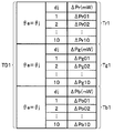
- the values of the output intensity differences ⁇ Pg01 and ⁇ Pg02 included in the table data Tr1, Tg1, and Tb1 are relative values with the output intensity difference ⁇ Pg01 as a reference value. Get as. Further, according to the work of the worker using the light emitting jigs JG1 and JG2 as described above, for example, a correction table TD1 having table data Tr1, Tg1, and Tb1 as shown in FIG. 4 is obtained. Is done. The correction table TD1 in FIG.
- FIG. 4 is a diagram illustrating an example of the correction table TD1 stored in the memory of the endoscope.
- the operator has a light emitting jig JG3 (not shown) configured to include a deviation direction value ⁇ jb that is different from the deviation direction value ⁇ e among 1 to 4, and a deviation distance value djm.
- the output intensity Pg11 of the G light emitted from the distal end portion of the insertion portion 11 (through the illumination fiber 12A) is measured using, for example, a measuring device such as an optical power meter. To do.
- the operator connects the SC connector of the light emitting jig JG4 (not shown) configured to include the deviation direction value ⁇ jb and the deviation distance value djn to the optical plug 71, for example, the optical power
- the output intensity Pg12 of the G light emitted from the distal end portion of the insertion portion 11 is measured (through the illumination fiber 12A).
- the operator uses the output intensities Pg11 and Pg12 measured as described above, and the output intensity difference ⁇ Pg11 obtained by subtracting Pg11 from the output intensity Pj and the output intensity difference ⁇ Pg12 obtained by subtracting Pg12 from the output intensity Pj. And are calculated respectively.
- the operator determines eight output intensity differences corresponding to each of the deviation distance values djm and deviation distance values djn, respectively.
- the table data Tg2 indicating the correspondence between the deviation distance value dj and the G light output intensity difference ⁇ Pg when the deviation direction value ⁇ e and the deviation direction value ⁇ j are different is acquired.
- the operator adds a predetermined value Vr1 to the value of each output intensity difference ⁇ Pg included in the table data Tg2, or from the value of each output intensity difference ⁇ Pg included in the table data Tg2 By subtracting Vr2, the table data Tr2 indicating the correspondence between the deviation distance value dj and the output intensity difference ⁇ Pr of the R light when the deviation direction value ⁇ e and the deviation direction value ⁇ j are different is obtained. Further, for example, the operator adds a predetermined value Vb1 to the value of each output intensity difference ⁇ Pg included in the table data Tg2, or from the value of each output intensity difference ⁇ Pg included in the table data Tg2. By subtracting Vb2, table data Tb2 indicating the correspondence between the shift distance value dj and the output intensity difference ⁇ Pb of the B light when the shift direction value ⁇ e and the shift direction value ⁇ j are different is acquired.
- the values of the output intensity differences other than the output intensity differences ⁇ Pg11 and ⁇ Pg12 included in the table data Tr2, Tg2, and Tb2 are relative values with the output intensity difference ⁇ Pg11 as a reference value. Get as. Further, according to the work of the worker using the light emitting jigs JG3 and JG4 as described above, for example, a correction table TD2 having table data Tr2, Tg2, and Tb2 as shown in FIG. 5 is acquired. Is done. The correction table TD2 in FIG.
- FIG. 5 is a diagram illustrating an example of the correction table TD2 stored in the memory of the endoscope.
- the operator then outputs output intensity correction data CDE having correction tables TD1 and TD2 obtained by work using the light emitting jigs JG1 to JG4 and a deviation direction value ⁇ e which is a known value. 2, the series of operations are completed.
- a correction method for correcting the output intensity of the illumination light emitted from the light source unit 21 As a correction method for correcting the output intensity of the illumination light emitted from the light source unit 21, a common method is used among the light sources of the red light source 31a, the green light source 31b, and the blue light source 31c. be able to. Therefore, hereinafter, a description will be given with a case where the output intensity of the R light emitted from the red light source 31a is corrected as a representative example.
- the light source control unit 26 reads the output characteristics Er, Eg, and Eb and the output intensity correction data CDB from the memory 24 when the power of the main unit 3 is turned on.
- the light source control unit 26 also connects the memory 16 of the endoscope 2 connected to the connector receiving unit 62 when the power of the main body device 3 is turned on and the endoscope 2 is connected to the main body device 3.
- the output intensity correction data CDE stored in is read.
- the light source control unit 26 determines whether or not the deviation direction value ⁇ b included in the output intensity correction data CDB and the deviation direction value ⁇ e included in the output intensity correction data CDE are the same.
- the output intensity is selected from the output intensity differences of the correction table TD1 included in the output intensity correction data CDE.
- Output intensity differences ⁇ Pr, ⁇ Pg, and ⁇ Pb associated with the shift distance value dj having the same value as the shift distance value db included in the correction data CDB are extracted.
- the deviation distance value db 1
- the output intensity differences ⁇ Pr01, ⁇ Pg01, and ⁇ Pb01 are extracted.
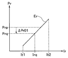
- the light source control unit 26 performs an operation for correcting the output intensity of the R light emitted from the red light source 31a using, for example, the output characteristic Er and the output intensity difference ⁇ Pr01. Specifically, for example, when the output intensity difference ⁇ Pr01 is a negative value and the target output intensity of R light is set to Prp, the light source control unit 26, as shown in FIG. By adding the value of the output intensity difference ⁇ Pr01 to the value of the target output intensity Prp, the corrected target output intensity Prq ( ⁇ Prp) of the R light is calculated, and corresponds to the calculated corrected target output intensity Prq of the R light.
- a current value Irq to be set is set based on the output characteristic Er, and a drive current having the set current value Irq is supplied to the red light source 31a.
- FIG. 6 is a diagram for explaining an example of an operation performed when correcting the output intensity of illumination light.
- the target output intensity Prp may be, for example, an output intensity that is set according to an operation of a brightness adjustment switch (not shown) for adjusting the brightness of the observation image displayed on the display device 4.
- the output intensity set according to the brightness of the observation image generated by the image generation unit 25 may be used.
- the output intensity differences ⁇ Pr, ⁇ Pg corresponding to the correction amount of the output intensity of the illumination light when the deviation direction value ⁇ e and the deviation direction value ⁇ b are the same.
- ⁇ Pb is configured as a table that can be specified for each of a plurality of shift distance values db.
- the optical plug 71 in which the positional deviation between the light emitting surface of the illumination fiber 12A and the light incident surface of the illumination fiber 12B is relatively small. And the optical receptacle 72 are connected, the amount of R light emitted from the distal end portion of the insertion portion 11 can be reduced to substantially the same amount as the amount of G light emitted from the distal end portion. .
- the output intensity is selected from the output intensity differences of the correction table TD2 included in the output intensity correction data CDE.
- Output intensity differences ⁇ Pr, ⁇ Pg, and ⁇ Pb associated with the shift distance value dj having the same value as the shift distance value db included in the correction data CDB are extracted.
- the output intensity differences ⁇ Pr20, ⁇ Pg20, and ⁇ Pb20 are extracted.
- the light source control unit 26 performs an operation for correcting the output intensity of the R light emitted from the red light source 31a using the output characteristic Er and the output intensity difference ⁇ Pr20.
- the output intensity difference ⁇ Pr20 is a positive value and the target output intensity of R light is set to Prx
- the corrected target output intensity Pry (> Prx) of the R light is calculated and corresponds to the calculated corrected target output intensity Pry of the R light.
- the current value Iry to be set is set based on the output characteristic Er, and the drive current having the set current value Iry is supplied to the red light source 31a.
- FIG. 7 is a diagram for explaining an example of an operation performed when correcting the output intensity of illumination light.
- the target output intensity Prx may be, for example, an output intensity that is set according to an operation of a brightness adjustment switch (not shown) for adjusting the brightness of the observation image displayed on the display device 4.
- the output intensity set according to the brightness of the observation image generated by the image generation unit 25 may be used.
- the correction table TD2 included in the output intensity correction data CDE indicates output intensity differences ⁇ Pr, ⁇ Pg, and ⁇ Pb corresponding to the correction amounts of the illumination light output intensity when the deviation direction value ⁇ e and the deviation direction value ⁇ b are different.
- the table is configured as a table that can be specified for each of the plurality of shift distance values db.
- the current value It2 is set to a current value corresponding to the rated current of the red light source 31a, and the current value Iry corresponding to the corrected target output intensity Pry of R light is the current value.
- the light source control unit 26 notifies, for example, the occurrence of a failure in the optical plug 71 or the optical receptacle 72 instead of supplying the drive current having the current value Iry to the red light source 31a.
- a predetermined message may be displayed on the display device 4.
- the optical plug 71 and the optical receptacle 72 when the optical plug 71 and the optical receptacle 72 are connected, there is a gap between the light exit surface of the illumination fiber 12A and the light incident surface of the illumination fiber 12B.
- the amount of R light, G light, and B light emitted from the distal end portion of the insertion portion 11 can be made substantially equal to each other irrespective of the magnitude of the positional deviation that occurs in FIG. Variation in the amount of illumination light emitted can be suppressed.
- the output intensity of the illumination light emitted from the illumination fiber 12A (from the distal end portion of the insertion unit 11) to the subject is determined in the standard related to the safety standard of the laser product.
- the output intensities of the R light, the G light, and the B light are corrected so as to be equal to or less than a predetermined value (for example, 5 mW), and the output intensities of the corrected R light, G light, and B light are further detected by the light detection unit 23 may be individually adjusted according to the spectral sensitivity characteristics of the 23 optical sensors or the color balance of the observation image displayed on the display device 4.
- the light source control unit 26 of the present embodiment may be configured to perform control for the light source unit 21 to simultaneously supply R light, G light, and B light to the illumination fiber 12B. Further, in such a case, the light source control unit 26 has, for example, the total value of the output intensity of each light included in the illumination light emitted from the illumination fiber 12A (from the distal end of the insertion unit 11) to the subject.
- the output intensity of the R light, G light, and B light is corrected so as to be equal to or less than a predetermined value (for example, 5 mW) defined in the standards relating to the safety standards of laser products, and the corrected R light, G light is further corrected.
- the output intensity of the B light may be individually adjusted according to the spectral sensitivity characteristic of the photosensor of the light detection unit 23 or the color balance of the observation image displayed on the display device 4.
- the light source control unit 26 of the present embodiment is not limited to changing the current value of the drive current supplied to each light source when correcting the output intensity of each light source of the light source unit 21.
- the light source unit The supply time (duty ratio) of the drive voltage supplied to each light source 21 may be changed.
- the connecting end portions of the optical plug 71 and the optical receptacle 72 are oriented so that the direction of the end face SF1 and the end face SF2 is the same as the shift direction value ⁇ b and the shift direction value ⁇ e.
- the output characteristic Ek corresponding to the representative characteristics of the three light sources of the red light source 31a, the green light source 31b, and the blue light source 31c is acquired, and R is obtained using the acquired output characteristic Ek. You may make it correct
- the deviation distance value de which is a value indicating how far the reference position CF1 and the center of the light incident surface SE1 are located is the same as the deviation distance value db.
- the output intensity correction data CDE including the shift distance value de may be stored in the memory 16 instead of the correction tables TD1 and TD2.
- the light source control unit 26 corrects the target output intensity based on the deviation direction values ⁇ e and ⁇ b and the deviation distance values de and db, and corresponds to the corrected target output intensity.
- the current value to be obtained may be acquired from the output characteristic Ek, and the output currents of the R light, G light, and B light may be corrected using the acquired current value.
Landscapes
- Health & Medical Sciences (AREA)
- Life Sciences & Earth Sciences (AREA)
- Physics & Mathematics (AREA)
- Surgery (AREA)
- Optics & Photonics (AREA)
- Biomedical Technology (AREA)
- Animal Behavior & Ethology (AREA)
- Radiology & Medical Imaging (AREA)
- Nuclear Medicine, Radiotherapy & Molecular Imaging (AREA)
- Engineering & Computer Science (AREA)
- Biophysics (AREA)
- Heart & Thoracic Surgery (AREA)
- Medical Informatics (AREA)
- Molecular Biology (AREA)
- Pathology (AREA)
- General Health & Medical Sciences (AREA)
- Public Health (AREA)
- Veterinary Medicine (AREA)
- Astronomy & Astrophysics (AREA)
- General Physics & Mathematics (AREA)
- Instruments For Viewing The Inside Of Hollow Bodies (AREA)
- Endoscopes (AREA)
Abstract
走査型内視鏡システムは、光源部から供給される照明光を用いて被写体を走査する内視鏡を具備し、内視鏡の外部に設けられ、光源部から供給される照明光を導く第1の光ファイバの出射端部が配置された第1の光コネクタと、内視鏡に設けられ、第1の光コネクタに接続されるとともに、第1の光ファイバの出射端部を経て出射される照明光を導く第2の光ファイバの入射端部が配置された第2の光コネクタと、第1の光コネクタにおける第1の光ファイバの出射端部の配置位置のずれ量を示す第1のパラメータと、第2の光コネクタにおける第2の光ファイバの入射端部の配置位置のずれ量を示す第2のパラメータと、に基づき、光源部から供給される照明光の出力強度を補正するための動作を行う光源制御部と、を有する。
Description
本発明は、走査型内視鏡システムに関し、特に、被写体を走査して画像を取得する走査型内視鏡システムに関するものである。
医療分野においては、例えば、日本国特許第5090579号公報に開示されているような電子式の内視鏡が従来用いられている。具体的には、日本国特許第5090579号公報には、光源装置から供給される照明光により照明された被写体をCCDで撮像するように構成された電子式の内視鏡が開示されている。
一方、医療分野においては、前述の電子式の内視鏡とは異なる構成を具備する内視鏡として、例えば、レーザ光等の高指向性を有する照明光を被写体に照射する際の照射位置を周期的に変化させることにより、当該被写体を光学的に走査するように構成された走査型の内視鏡が近年提案されている。
ところで、走査型の内視鏡においては、被検者の体腔内に挿入される挿入部にCCD等の固体撮像素子を設ける必要がないため、当該挿入部を電子式の内視鏡よりも細径化することができる、という利点が存在する。また、走査型の内視鏡においては、前述の利点を極力活かすために、例えば、照明光を導光する光導波路として単一の光ファイバを用いるような構成が望ましいと考えられている。そのため、走査型の内視鏡においては、多数の光ファイバを束ねたライトガイドを光導波路として用いることが可能な電子式の内視鏡に比べて被写体へ照射される照明光の光量がばらつき易い、という問題点が生じ得る。
しかし、日本国特許第5090579号公報には、前述のような走査型の内視鏡の構成上の問題点を解消可能な構成について特に開示等されておらず、すなわち、前述の問題点に応じた課題が依然として存在している。
本発明は、前述した事情に鑑みてなされたものであり、被写体へ照射される照明光の光量のばらつきを抑制可能な走査型内視鏡システムを提供することを目的としている。
本発明の一態様の走査型内視鏡システムは、光源部から供給される照明光を用いて被写体を走査するように構成された内視鏡を具備する走査型内視鏡システムであって、前記内視鏡の外部に設けられ、前記光源部から供給される前記照明光を導く第1の光ファイバの出射端部が配置された第1の光コネクタと、前記内視鏡に設けられ、前記第1の光コネクタに接続されるとともに、前記第1の光ファイバの出射端部を経て出射される前記照明光を導く第2の光ファイバの入射端部が配置された第2の光コネクタと、前記第1の光コネクタにおける前記第1の光ファイバの出射端部の配置位置のずれ量を示す1つ以上のパラメータである第1のパラメータと、前記第2の光コネクタにおける前記第2の光ファイバの入射端部の配置位置のずれ量を示す1つ以上のパラメータである第2のパラメータと、に基づき、前記光源部から供給される前記照明光の出力強度を補正するための動作を行うように構成された光源制御部と、を有する。
以下、本発明の実施の形態について、図面を参照しつつ説明を行う。
図1から図7は、本発明の実施例に係るものである。
走査型内視鏡システム1は、図1に示すように、被検者の体腔内に挿入される走査型の内視鏡2と、内視鏡2を着脱自在に接続可能な本体装置3と、本体装置3に接続される表示装置4と、を有して構成されている。図1は、実施例に係る走査型内視鏡システムの要部の構成を示す図である。
内視鏡2は、被検者の体腔内に挿入可能な細長形状及び可撓性を備えて形成された挿入部11を有して構成されている。また、内視鏡2は、本体装置3の光源部21(後述)から供給される照明光を用いて被写体を走査するように構成されている。
挿入部11の基端部には、内視鏡2を本体装置3のコネクタ受け部62に着脱自在に接続するためのコネクタ部61が設けられている。
コネクタ部61及びコネクタ受け部62の内部には、内視鏡2と本体装置3とを電気的に接続するための電気コネクタ装置(不図示)が設けられている。また、コネクタ部61の内部には、本体装置3の光レセプタクル72に接続される光コネクタである光プラグ71が設けられている。また、コネクタ受け部62の内部には、内視鏡2の光プラグ71に接続される光コネクタである光レセプタクル72が設けられている。また、コネクタ部61及びコネクタ受け部62の内部には、内視鏡2の受光用ファイバ13Aと本体装置3の受光用ファイバ13Bとを光学的に接続するための光コネクタ装置(不図示)が設けられている。なお、以降においては、光プラグ71及び光レセプタクル72がSCコネクタとして形成されているものとして説明を行う。
挿入部11の内部における基端部から先端部にかけての部分には、照明用ファイバ12Bの出射端部を経て出射される照明光(本体装置3から供給される照明光)を集光光学系14へ導くための光ファイバである照明用ファイバ12Aと、被写体からの戻り光を受光して本体装置3へ導くための光ファイバである受光用ファイバ13Aと、がそれぞれ挿通されている。
照明用ファイバ12Aは、例えば、1本のシングルモードファイバにより構成されている。また、照明用ファイバ12Aの光入射面を含む入射端部は、光プラグ71の内部に配置されている。また、照明用ファイバ12Aの光出射面を含む出射端部は、挿入部11の先端部に設けられたレンズ14aの光入射面の近傍に配置されている。
受光用ファイバ13Aは、例えば、複数本のマルチモードファイバを束ねて構成されている。また、受光用ファイバ13Aの光入射面を含む入射端部は、挿入部11の先端部の先端面における、レンズ14bの光出射面の周囲に固定配置されている。また、受光用ファイバ13Aの光出射面を含む出射端部は、コネクタ部61の内部に配置されている。
集光光学系14は、照明用ファイバ12Aの光出射面を経た光が入射されるレンズ14aと、レンズ14aを経た光を被写体へ出射するレンズ14bと、を有して構成されている。
挿入部11の先端部側における照明用ファイバ12Aの中途部には、本体装置3の走査制御部22から供給される駆動信号に基づいて駆動することにより、照明用ファイバ12Aの出射端部を揺動させることができるように構成されたアクチュエータ部15が設けられている。
アクチュエータ部15は、例えば、本体装置3の走査制御部22から供給される駆動信号に基づいて駆動することにより、照明用ファイバ12Aの出射端部を第1の方向に沿って揺動させることが可能な1つ以上の圧電素子を備えた第1のアクチュエータと、本体装置3の走査制御部22から供給される駆動信号に基づいて駆動することにより、当該出射端部を当該第1の方向に直交する第2の方向に揺動させることが可能な1つ以上の圧電素子を備えた第2のアクチュエータと、を具備して構成されている。
挿入部11の内部には、内視鏡2毎に固有のデータであるとともに、本体装置3の光源制御部26の動作に用いられるデータである出力強度補正用データCDEが格納されたメモリ16が設けられている。具体的には、メモリ16には、例えば、光プラグ71における照明用ファイバ12Aの入射端部の配置位置のずれ量を示すパラメータと、当該パラメータに対応する照明光の出力強度の補正テーブルと、を含む出力強度補正用データCDEが格納されている。そして、メモリ16に格納された出力強度補正用データCDEは、内視鏡2のコネクタ部61と本体装置3のコネクタ受け部62とが接続された際に、本体装置3の光源制御部26により読み出される。
ここで、光プラグ71における照明用ファイバ12Aの入射端部の配置位置のずれ量を示すパラメータの取得方法の具体例等について説明する。
光プラグ71の接続端部は、正面側から見た場合に、例えば、図2に模式的に示すような矩形の外形を有して形成されている。また、光プラグ71の接続端部は、例えば、図2に模式的に示すように、照明用ファイバ12Aの入射端部を円柱形状のフェルールFR1の内部に固定配置した状態において、照明用ファイバ12Aの光入射面SE1とフェルールFR1の端面SF1とを同一平面上に配置して形成されている。図2は、内視鏡に設けられた光プラグの接続端部の形状の一例を説明するための模式図である。
そのため、本実施例においては、例えば、フェルールFR1の端面SF1の中心に相当する基準位置CF1と、基準位置CF1において直交する2本の仮想線分(図2の一点鎖線L1及びL2)と、をそれぞれ設定することにより、光入射面SE1及び基準位置CF1を含む平面を当該2本の仮想線分で分割した4つの領域AP1~AP4のうちのどの領域に光入射面SE1の中心が位置しているかを示す値であるずれ方向値θeを、光プラグ71における照明用ファイバ12Aの入射端部の配置位置のずれ量を示すパラメータとして取得することができる。具体的には、ずれ方向値θeは、例えば、光入射面SE1の中心が領域AP1に位置する場合に1となり、光入射面SE1の中心が領域AP2に位置する場合(図2に示した場合)に2となり、光入射面SE1の中心が領域AP3に位置する場合に3となり、かつ、光入射面SE1の中心が領域AP4に位置する場合に4となるような値として取得される。すなわち、ずれ方向値θeは、照明用ファイバ12Aの入射端部の光入射面SE1が光プラグ71において設定される基準位置CF1からどの方向へずれているかを示す値として取得される。なお、ずれ方向値θeに対応する照明光の出力強度の補正テーブルの取得方法については、後程説明する。
本体装置3は、光源部21と、走査制御部22と、光検出部23と、メモリ24と、画像生成部25と、光源制御部26と、を有して構成されている。また、本体装置3の所定の位置には、内視鏡2のコネクタ部61を着脱自在に接続するためのコネクタ受け部62が設けられている。また、本体装置3の内部には、光源部21から供給される照明光をコネクタ受け部62へ導くための光ファイバである照明用ファイバ12Bと、受光用ファイバ13Aの出射端部を経て出射される戻り光(内視鏡2において受光された戻り光)を光検出部23へ導くための光ファイバである受光用ファイバ13Bと、がそれぞれ設けられている。
照明用ファイバ12Bは、例えば、1本のシングルモードファイバにより構成されている。また、照明用ファイバ12Bの光入射面を含む入射端部は、光源部21に配置されている。また、照明用ファイバ12Bの光出射面を含む出射端部は、光レセプタクル72の内部に配置されている。
受光用ファイバ13Bは、例えば、複数本のマルチモードファイバを束ねて構成されている。また、受光用ファイバ13Bの光入射面を含む入射端部は、コネクタ受け部62の内部に配置されている。また、受光用ファイバ13Bの光出射面を含む出射端部は、光検出部23に配置されている。
光源部21は、赤色光源31aと、緑色光源31bと、青色光源31cと、合波器32と、を有して構成されている。
赤色光源31aは、例えば、レーザ光源等を具備し、光源制御部26から供給される駆動電流の大きさに応じた出力強度で赤色の波長帯域のレーザ光(以降、R光とも称する)を発生するように構成されている。
緑色光源31bは、例えば、レーザ光源等を具備し、光源制御部26から供給される駆動電流の大きさに応じた出力強度で緑色の波長帯域のレーザ光(以降、G光とも称する)を発生するように構成されている。
青色光源31cは、例えば、レーザ光源等を具備し、光源制御部26から供給される駆動電流の大きさに応じた出力強度で青色の波長帯域のレーザ光(以降、B光とも称する)を発生するように構成されている。
合波器32は、赤色光源31aから発せられるR光、緑色光源31bから発せられるG光、及び、青色光源31cから発せられるB光をそれぞれ照明用ファイバ12Bの光入射面へ出射することができるように構成されている。
すなわち、光源部21は、R光、G光及びB光を照明光として照明用ファイバ12Bに供給することができるように構成されている。
走査制御部22は、例えば、信号発生器等を具備して構成されている。また、走査制御部22は、メモリ24に格納されている走査制御情報に基づき、照明用ファイバ12Aの出射端部を渦巻状等の所定の走査パターンで揺動させるための駆動信号を生成し、当該生成した駆動信号をアクチュエータ部15へ供給するように構成されている。なお、本実施例によれば、走査制御部22において生成された駆動信号をアクチュエータ部15へ供給する際に使用される信号線の途中に、例えば、バリスタまたは耐圧コンデンサ等の電子部品を設けてもよい。そして、このような構成によれば、例えば、アクチュエータ部15に対する静電気の印加を防止することができる。
光検出部23は、例えば、分波器、光センサ及びA/D変換器等を具備して構成されている。また、光検出部23は、受光用ファイバ13Bの出射端部を経て出射される戻り光を検出し、当該検出した戻り光の強度に応じた輝度値を示すデジタル信号である光検出信号を生成し、当該生成した光検出信号を画像生成部25へ出力するように構成されている。
メモリ24には、例えば、振幅及び周波数等のような、アクチュエータ部15へ供給される駆動信号の信号波形を特定可能なパラメータを具備する走査制御情報が格納されている。また、メモリ24には、光検出部23から順次出力される光検出信号の出力タイミングと、当該光検出信号を変換して得られる画素情報の適用先となる画素位置と、の間の対応関係を示すテーブルであるマッピングテーブルが格納されている。また、メモリ24には、本体装置3毎に固有のデータであるとともに、光源制御部26の動作に用いられるデータである出力強度補正用データCDBが格納されている。具体的には、メモリ24には、例えば、光レセプタクル72における照明用ファイバ12Bの出射端部の配置位置のずれ量を示すパラメータを含む出力強度補正用データCDBが格納されている。
ここで、光レセプタクル72における照明用ファイバ12Bの出射端部の配置位置のずれ量を示すパラメータの取得方法の具体例等について説明する。
光レセプタクル72の接続端部は、正面側から見た場合に、例えば、図3に模式的に示すような矩形の外形を有して形成されている。また、光レセプタクル72の接続端部は、例えば、図3に模式的に示すように、照明用ファイバ12Bの出射端部を円柱形状のフェルールFR2の内部に固定配置した状態において、照明用ファイバ12Bの光出射面SE2とフェルールFR2の端面SF2とを同一平面上に配置して形成されている。図3は、本体装置に設けられた光レセプタクルの接続端部の形状の一例を説明するための模式図である。
そのため、本実施例においては、例えば、フェルールFR2の端面SF2の中心に相当する基準位置CF2と、基準位置CF2において直交する2本の仮想線分(図3の一点鎖線L3及びL4)と、をそれぞれ設定することにより、光出射面SE2及び基準位置CF2を含む平面を当該2本の仮想線分で分割した4つの領域AQ1~AQ4のうちのどの領域に光入射面SE2の中心が位置しているかを示す値であるずれ方向値θbを、光レセプタクル72における照明用ファイバ12Bの出射端部の配置位置のずれ量を示すパラメータとして取得することができる。具体的には、ずれ方向値θbは、例えば、光出射面SE2の中心が領域AQ1に位置する場合に1となり、光出射面SE2の中心が領域AQ2に位置する場合に2となり、光出射面SE2の中心が領域AQ3に位置する場合に3となり、かつ、光出射面SE2の中心が領域AQ4に位置する場合(図3に示した場合)に4となるような値として取得される。すなわち、ずれ方向値θbは、照明用ファイバ12Bの出射端部の光出射面SE2が光レセプタクル72において設定される基準位置CF2からどの方向へずれているかを示す値として取得される。
なお、ずれ方向値θbは、実際の作業における難易度を考慮した場合、光源部21から発せられる所定の色の照明光の結合効率の大きさに応じて取得されることが望ましい。具体的には、例えば、既知のずれ方向値を有するプラグ形の治具をレセプタクル72に接続し、かつ、光源部21から所定の色の照明光を出射させた状態において、当該治具を回転させながら当該所定の色の照明光の結合効率を順次測定するとともに、当該測定した結合効率が最大となる回転位置が領域AQ1~AQ4のうちのどの領域に属するかに応じてレセプタクル72のずれ方向値θbを(1から4のうちのいずれかの値として)取得すればよい。
また、本実施例においては、光出射面SE2の中心が基準位置CF2からどれだけ離れているかを示す値であるずれ距離値dbを、光レセプタクル72における照明用ファイバ12Bの出射端部の配置位置のずれ量を示すパラメータとして併せて取得することができる。具体的には、ずれ距離値dbは、例えば、基準位置CF2と光出射面SE2の中心との間における実際の距離の大きさを1から10の10段階に分けて離散化した値として取得される。
なお、ずれ距離値dbは、実際の作業における難易度を考慮した場合、光源部21から発せられる所定の色の照明光の結合効率の大きさに応じて取得されることが望ましい。具体的には、例えば、既知の小さなずれ距離値を有するプラグ形の治具をレセプタクル72に接続し、かつ、光源部21から所定の色の照明光を出射させた状態において、当該所定の色の照明光の結合効率を測定するとともに、当該測定した結合効率がどの程度の大きさになるかに応じてレセプタクル72のずれ距離値dbを(1から10のうちのいずれかの値として)取得すればよい。
そして、本実施例によれば、本体装置3の光レセプタクル72のずれ距離値dbが、(実測値ではなく、)10段階に離散化された値として取得されるため、例えば、メモリ16に格納される出力強度補正用データCDE(後述の補正テーブルTD1及びTD2に含まれる各テーブルデータ)のデータ量を極力抑制することができる。
一方、メモリ24には、赤色光源31aのレーザ発振時における駆動電流の電流値IrとR光の出力強度Prとの間の相関を示す出力特性Erと、緑色光源31bのレーザ発振時における駆動電流の電流値IgとG光の出力強度Pgとの間の相関を示す出力特性Egと、青色光源31cのレーザ発振時における駆動電流の電流値IbとB光の出力強度Pbとの間の相関を示す出力特性Ebと、が格納されている。
具体的には、出力特性Erは、例えば、光レセプタクル72の接続端部に光パワーメータ等の計測機器を接続した状態において、光源制御部26から赤色光源31aに供給される駆動電流の電流値Irを、0<It1<It2の条件を満たす電流値It1から電流値It2までの間で連続的にまたは離散的に変化させつつ、照明用ファイバ12Bの出射端面から出射されるR光の出力強度Prを計測することにより取得される。また、出力特性Egは、例えば、光レセプタクル72の接続端部に光パワーメータ等の計測機器を接続した状態において、光源制御部26から緑色光源31bに供給される駆動電流の電流値Igを、0<It3<It4の条件を満たす電流値It3から電流値It4までの間で連続的にまたは離散的に変化させつつ、照明用ファイバ12Bの出射端面から出射されるG光の出力強度Pgを計測することにより取得される。また、出力特性Ebは、例えば、光レセプタクル72の接続端部に光パワーメータ等の計測機器を接続した状態において、光源制御部26から青色光源31cに供給される駆動電流の電流値Ibを、0<It5<It6の条件を満たす電流値It5から電流値It6までの間で連続的にまたは離散的に変化させつつ、照明用ファイバ12Bの出射端面から出射されるB光の出力強度Pbを計測することにより取得される。なお、前述の電流値It1、It3及びIt5は、赤色光源31a、緑色光源31b及び青色光源31cのレーザ発振が開始される閾値電流以上の値としてそれぞれ設定されるものとする。また、前述の電流値It2、It4及びIt6は、例えば、赤色光源31a、緑色光源31b及び青色光源31cの定格電流以下の電流値としてそれぞれ設定されるものとする。また、本実施例においては、出力特性Er、Eg及びEbがそれぞれ線形性を具備している(一次関数として表現される)ものとして説明を行う。
画像生成部25は、例えば、画像生成回路を具備して構成されている。また、画像生成部25は、光検出部23から出力される光検出信号をRGB成分等の画素情報に変換し、当該変換した画素情報をメモリ24に格納されたマッピングテーブルに対応する位置の画素にマッピングすることにより観察画像を1フレーム分ずつ生成し、当該生成した観察画像を表示装置4へ順次出力するように構成されている。
光源制御部26は、光源部21の各光源を駆動するための駆動電流を供給することができるように構成されている。また、光源制御部26は、例えば、R光、G光及びB光をこの順番で繰り返し照明用ファイバ12Bに供給させるための制御を光源部21に対して行うように構成されている。また、光源制御部26は、メモリ24に格納された出力特性Er、Eg及びEbに基づいて光源部21の各光源に供給する駆動電流の電流値を設定することにより、当該設定した駆動電流の電流値に応じた出力強度の照明光を光源部21から照明用ファイバ12Bに供給させることができるように構成されている。また、光源制御部26は、コネクタ受け部62に接続されている内視鏡2のメモリ16に格納された出力強度補正用データCDEと、メモリ24に格納された出力強度補正用データCDBと、に基づき、出力特性Er、Eg及びEbにより特定される各光源の出力強度を補正するための動作を行うように構成されている。なお、光源制御部26において行われる動作の詳細については、後程説明する。
続いて、以上に述べたような構成を具備する走査型内視鏡システム1の動作等について説明する。
まず、メモリ16に格納される出力強度補正用データCDEに含まれる補正テーブルの取得方法の具体例について説明する。なお、以降の説明においては、光レセプタクル72と略同様の形状に形成されたSCコネクタを具備するとともに、所定の出力強度PjのG光(緑色の波長帯域のレーザ光)を当該SCコネクタから発する各発光治具を用いて補正テーブルを取得する場合を例に挙げて説明する。また、以降においては、光プラグ71のずれ方向値θeが予め取得されているものと仮定して説明する。また、以降においては、補正テーブルの取得に用いられる各発光治具のSCコネクタのずれ方向値θjがずれ方向値θbと同様の方法を用いて予め取得されているとともに、当該各発光治具のSCコネクタのずれ距離値djがずれ距離値dbと同様の方法を用いて予め取得されているものと仮定して説明する。
作業者は、1から4のうちのずれ方向値θeと同じ値であるずれ方向値θjaと、1から10のうちのいずれかの値であるずれ距離値djmと、を具備するように構成された発光治具JG1(不図示)のSCコネクタを光プラグ71に接続した後、例えば、光パワーメータ等の計測機器を用い、(照明用ファイバ12Aを経て)挿入部11の先端部から出射されるG光の出力強度Pg01を計測する。また、作業者は、ずれ方向値θjaと、1から10のうちのずれ距離値djmとは異なる値であるずれ距離値djnと、を具備するように構成された発光治具JG2(不図示)のSCコネクタを光プラグ71に接続した後、例えば、光パワーメータ等の計測機器を用い、(照明用ファイバ12Aを経て)挿入部11の先端部から出射されるG光の出力強度Pg02を計測する。そして、作業者は、前述のように計測した出力強度Pg01及びPg02を用い、出力強度PjからPg01を減じて得られる出力強度差ΔPg01と、出力強度PjからPg02を減じて得られる出力強度差ΔPg02と、をそれぞれ算出する。
作業者は、例えば、出力強度差ΔPg01に対する出力強度差ΔPg02の変化量(差分値)に基づき、ずれ距離値djm及びずれ距離値djn以外の各ずれ距離値に対応する8つの出力強度差をそれぞれ算出することにより、ずれ方向値θeとずれ方向値θjとが同じである場合におけるずれ距離値djとG光の出力強度差ΔPgとの間の対応関係を示すテーブルデータTg1を取得する。また、作業者は、例えば、テーブルデータTg1に含まれる各出力強度差ΔPgの値に対して所定値Vr1を加えることにより、または、テーブルデータTg1に含まれる各出力強度差ΔPgの値から所定値Vr2を減じることにより、ずれ方向値θeとずれ方向値θjとが同じである場合におけるずれ距離値djとR光の出力強度差ΔPrとの間の対応関係を示すテーブルデータTr1を取得する。また、作業者は、例えば、テーブルデータTg1に含まれる各出力強度差ΔPgの値に対して所定値Vb1を加えることにより、または、テーブルデータTg1に含まれる各出力強度差ΔPgの値から所定値Vb2を減じることにより、ずれ方向値θeとずれ方向値θjとが同じである場合におけるずれ距離値djとB光の出力強度差ΔPbとの間の対応関係を示すテーブルデータTb1を取得する。
なお、所定値Vr1及びVr2は、例えば、G光の帯域における伝送損失及びR光の帯域における伝送損失等のような、照明用ファイバ12Aの特性に係るパラメータに基づいて設定すればよい。また、所定値Vb1及びVb2は、例えば、G光の帯域における伝送損失及びB光の帯域における伝送損失等のような、照明用ファイバ12Aの特性に係るパラメータに基づいて設定すればよい。
そして、以上に述べたような作業によれば、テーブルデータTr1、Tg1及びTb1に含まれる出力強度差ΔPg01及びΔPg02以外の各出力強度差の値が、出力強度差ΔPg01を基準値とする相対値として取得される。また、以上に述べたような、発光治具JG1及びJG2を用いた作業者の作業によれば、例えば、図4に示すような、テーブルデータTr1、Tg1及びTb1を具備する補正テーブルTD1が取得される。なお、図4の補正テーブルTD1は、θe=θjaかつdjm=1の発光治具JG1と、θe=θjaかつdjn=2の発光治具JG2と、を用いた作業により取得される補正テーブルの一例を示すものとする。図4は、内視鏡のメモリに格納される補正テーブルTD1の一例を示す図である。
一方、作業者は、1から4のうちのずれ方向値θeとは異なる値であるずれ方向値θjbと、ずれ距離値djmと、を具備するように構成された発光治具JG3(不図示)のSCコネクタを光プラグ71に接続した後、例えば、光パワーメータ等の計測機器を用い、(照明用ファイバ12Aを経て)挿入部11の先端部から出射されるG光の出力強度Pg11を計測する。また、作業者は、ずれ方向値θjbと、ずれ距離値djnと、を具備するように構成された発光治具JG4(不図示)のSCコネクタを光プラグ71に接続した後、例えば、光パワーメータ等の計測機器を用い、(照明用ファイバ12Aを経て)挿入部11の先端部から出射されるG光の出力強度Pg12を計測する。そして、作業者は、前述のように計測した出力強度Pg11及びPg12を用い、出力強度PjからPg11を減じて得られる出力強度差ΔPg11と、出力強度PjからPg12を減じて得られる出力強度差ΔPg12と、をそれぞれ算出する。
作業者は、例えば、出力強度差ΔPg11に対する出力強度差ΔPg12の変化量(差分値)に基づき、ずれ距離値djm及びずれ距離値djn以外の各ずれ距離値に対応する8つの出力強度差をそれぞれ算出することにより、ずれ方向値θeとずれ方向値θjとが異なる場合におけるずれ距離値djとG光の出力強度差ΔPgとの間の対応関係を示すテーブルデータTg2を取得する。また、作業者は、例えば、テーブルデータTg2に含まれる各出力強度差ΔPgの値に対して所定値Vr1を加えることにより、または、テーブルデータTg2に含まれる各出力強度差ΔPgの値から所定値Vr2を減じることにより、ずれ方向値θeとずれ方向値θjとが異なる場合におけるずれ距離値djとR光の出力強度差ΔPrとの間の対応関係を示すテーブルデータTr2を取得する。また、作業者は、例えば、テーブルデータTg2に含まれる各出力強度差ΔPgの値に対して所定値Vb1を加えることにより、または、テーブルデータTg2に含まれる各出力強度差ΔPgの値から所定値Vb2を減じることにより、ずれ方向値θeとずれ方向値θjとが異なる場合におけるずれ距離値djとB光の出力強度差ΔPbとの間の対応関係を示すテーブルデータTb2を取得する。
そして、以上に述べたような作業によれば、テーブルデータTr2、Tg2及びTb2に含まれる出力強度差ΔPg11及びΔPg12以外の各出力強度差の値が、出力強度差ΔPg11を基準値とする相対値として取得される。また、以上に述べたような、発光治具JG3及びJG4を用いた作業者の作業によれば、例えば、図5に示すような、テーブルデータTr2、Tg2及びTb2を具備する補正テーブルTD2が取得される。なお、図5の補正テーブルTD2は、θe≠θjaかつdjm=1の発光治具JG3と、θe≠θjaかつdjn=2の発光治具JG4と、を用いた作業により取得される補正テーブルの一例を示すものとする。図5は、内視鏡のメモリに格納される補正テーブルTD2の一例を示す図である。
そして、作業者は、発光治具JG1~JG4を用いた作業により取得した補正テーブルTD1及びTD2と、既知の値であるずれ方向値θeと、を具備する出力強度補正用データCDEを内視鏡2のメモリ16に格納した後、一連の作業を完了する。
次に、光源制御部26において行われる動作の具体例について説明する。なお、本実施例においては、光源部21から発せられる照明光の出力強度を補正するための補正方法として、赤色光源31a、緑色光源31b及び青色光源31cの各光源間で共通の方法を利用することができる。そのため、以降においては、赤色光源31aから発せられるR光の出力強度を補正する場合を代表例として挙げつつ説明を行う。
光源制御部26は、本体装置3の電源が投入された際に、出力特性Er、Eg及びEbと、出力強度補正用データCDBと、をメモリ24から読み込む。また、光源制御部26は、本体装置3の電源が投入され、かつ、内視鏡2が本体装置3に接続された際に、コネクタ受け部62に接続されている内視鏡2のメモリ16に格納された出力強度補正用データCDEを読み込む。
その後、光源制御部26は、出力強度補正用データCDBに含まれるずれ方向値θbと、出力強度補正用データCDEに含まれるずれ方向値θeと、が同じであるか否かを判定する。
光源制御部26は、ずれ方向値θbとずれ方向値θeとが同じであることを検出した際に、出力強度補正用データCDEに含まれる補正テーブルTD1の各出力強度差の中から、出力強度補正用データCDBに含まれるずれ距離値dbと同じ値のずれ距離値djに対応付けられた出力強度差ΔPr、ΔPg及びΔPbをそれぞれ抽出する。具体的には、光源制御部26は、例えば、ずれ距離値db=1である場合には、図4の補正テーブルTD1の各出力強度差の中から、ずれ距離値dj=1に対応付けられた出力強度差ΔPr01、ΔPg01及びΔPb01をそれぞれ抽出する。
そして、光源制御部26は、例えば、出力特性Er及び出力強度差ΔPr01を用い、赤色光源31aから発せられるR光の出力強度を補正するための動作を行う。具体的には、光源制御部26は、例えば、出力強度差ΔPr01が負の値であり、かつ、R光の目標出力強度がPrpに設定された場合には、図6に示すように、当該目標出力強度Prpの値に出力強度差ΔPr01の値を加えることにより補正後のR光の目標出力強度Prq(<Prp)を算出し、当該算出した補正後のR光の目標出力強度Prqに対応する電流値Irqを出力特性Erに基づいて設定し、当該設定した電流値Irqを具備する駆動電流を赤色光源31aに供給する。図6は、照明光の出力強度の補正時に行われる動作の一例を説明するための図である。なお、目標出力強度Prpは、例えば、表示装置4に表示される観察画像の明るさを調整するための明るさ調整スイッチ(不図示)の操作に応じて設定される出力強度であってもよく、または、画像生成部25により生成される観察画像の明るさに応じて設定される出力強度であってもよい。
すなわち、出力強度補正用データCDEに含まれる補正テーブルTD1は、ずれ方向値θeとずれ方向値θbとが同じである場合における照明光の出力強度の補正量に相当する出力強度差ΔPr、ΔPg及びΔPbを、複数のずれ距離値db毎に特定可能なテーブルとして構成されている。
また、以上に述べたような光源制御部26の動作によれば、例えば、照明用ファイバ12Aの光出射面と照明用ファイバ12Bの光入射面との間の位置ずれが比較的小さな光プラグ71と光レセプタクル72とが接続されている場合に、挿入部11の先端部から出射されるR光の光量を、当該先端部から出射されるG光の光量と略同じ光量まで低下させることができる。
一方、光源制御部26は、ずれ方向値θbとずれ方向値θeとが異なることを検出した際に、出力強度補正用データCDEに含まれる補正テーブルTD2の各出力強度差の中から、出力強度補正用データCDBに含まれるずれ距離値dbと同じ値のずれ距離値djに対応付けられた出力強度差ΔPr、ΔPg及びΔPbをそれぞれ抽出する。具体的には、光源制御部26は、例えば、ずれ距離値db=10である場合には、図5の補正テーブルTD2の各出力強度差の中から、ずれ距離値dj=10に対応付けられた出力強度差ΔPr20、ΔPg20及びΔPb20をそれぞれ抽出する。
そして、光源制御部26は、出力特性Er及び出力強度差ΔPr20を用い、赤色光源31aから発せられるR光の出力強度を補正するための動作を行う。具体的には、光源制御部26は、例えば、出力強度差ΔPr20が正の値であり、かつ、R光の目標出力強度がPrxに設定された場合には、図7に示すように、当該目標出力強度Prxの値に出力強度差ΔPr20の値を加えることにより補正後のR光の目標出力強度Pry(>Prx)を算出し、当該算出した補正後のR光の目標出力強度Pryに対応する電流値Iryを出力特性Erに基づいて設定し、当該設定した電流値Iryを具備する駆動電流を赤色光源31aに供給する。図7は、照明光の出力強度の補正時に行われる動作の一例を説明するための図である。なお、目標出力強度Prxは、例えば、表示装置4に表示される観察画像の明るさを調整するための明るさ調整スイッチ(不図示)の操作に応じて設定される出力強度であってもよく、または、画像生成部25により生成される観察画像の明るさに応じて設定される出力強度であってもよい。
すなわち、出力強度補正用データCDEに含まれる補正テーブルTD2は、ずれ方向値θeとずれ方向値θbとが異なる場合における照明光の出力強度の補正量に相当する出力強度差ΔPr、ΔPg及びΔPbを、複数のずれ距離値db毎に特定可能なテーブルとして構成されている。
また、以上に述べたような光源制御部26の動作によれば、例えば、照明用ファイバ12Aの光出射面と照明用ファイバ12Bの光入射面との間の位置ずれが比較的大きな光プラグ71と光レセプタクル72とが接続されている場合に、挿入部11の先端部から出射されるR光の光量を、当該先端部から出射されるG光の光量と略同じ光量まで上昇させることができる。
なお、本実施例によれば、例えば、電流値It2が赤色光源31aの定格電流に相当する電流値に設定され、かつ、補正後のR光の目標出力強度Pryに対応する電流値Iryが電流値It2を超えるような場合において、光源制御部26が、電流値Iryを具備する駆動電流を赤色光源31aに供給する代わりに、例えば、光プラグ71または光レセプタクル72における不具合の発生等を報知するための所定のメッセージを表示装置4に表示させるようにしてもよい。
以上に述べたように、本実施例によれば、光プラグ71と光レセプタクル72とが接続されている際に、照明用ファイバ12Aの光出射面と照明用ファイバ12Bの光入射面との間において生じる位置ずれの大きさによらずに、挿入部11の先端部から出射されるR光、G光及びB光の光量を相互に略同じ光量にすることができ、その結果、被写体へ照射される照明光の光量のばらつきを抑制することができる。
なお、本実施例の光源制御部26は、例えば、照明用ファイバ12Aを経て(挿入部11の先端部から)被写体へ出射される照明光の出力強度がレーザ製品の安全基準に係る規格において定められている所定値(例えば5mW)以下になるようにR光、G光及びB光の出力強度をそれぞれ補正し、さらに、当該補正したR光、G光及びB光の出力強度を光検出部23の光センサの分光感度特性または表示装置4に表示される観察画像のカラーバランス等に応じて個別に調整するようにしてもよい。
また、本実施例の光源制御部26は、R光、G光及びB光を同時に照明用ファイバ12Bに供給させるための制御を光源部21に対して行うように構成されていてもよい。また、このような場合において、光源制御部26は、例えば、照明用ファイバ12Aを経て(挿入部11の先端部から)被写体へ出射される照明光に含まれる各光の出力強度の合計値がレーザ製品の安全基準に係る規格において定められている所定値(例えば5mW)以下になるようにR光、G光及びB光の出力強度をそれぞれ補正し、さらに、当該補正したR光、G光及びB光の出力強度を光検出部23の光センサの分光感度特性または表示装置4に表示される観察画像のカラーバランス等に応じて個別に調整するようにしてもよい。
また、本実施例の光源制御部26は、光源部21の各光源の出力強度を補正する際に、当該各光源に供給する駆動電流の電流値を変化させるものに限らず、例えば、光源部21の各光源に供給する駆動電圧の供給時間(デューティー比)を変化させるようにしてもよい。
なお、本実施例によれば、例えば、光プラグ71及び光レセプタクル72の接続端部が、端面SF1及び端面SF2の向きをずれ方向値θbとずれ方向値θeとが同じになるような向きに合わせて接続するための接続機構等を具備して構成されていてもよい。具体的には、光プラグ71及び光レセプタクル72が、例えば、端面SF1及び端面SF2の向きがずれ方向値θe=θb=1となる向きに合わせられている場合に限り、一方の接続端部に設けられた凸部を他方の接続端部に設けられた凹部に嵌合させることができるような構成を具備していてもよい。そして、このような構成によれば、メモリ16に格納される出力強度補正用データCDEからずれ方向値θe及び補正テーブルTD2を除くことができるとともに、メモリ24に格納される出力強度補正用データCDBからずれ方向値θbを除くことができる。
また、本実施例によれば、例えば、赤色光源31a、緑色光源31b及び青色光源31cの3つの光源の代表特性に相当する出力特性Ekを取得するとともに、当該取得した出力特性Ekを用いてR光、G光及びB光の出力強度をそれぞれ補正するようにしてもよい。
また、本実施例によれば、例えば、基準位置CF1と光入射面SE1の中心とがどの程度離れた距離に位置しているかを示す値であるずれ距離値deをずれ距離値dbと同様の方法を用いて取得するとともに、補正テーブルTD1及びTD2の代わりにずれ距離値deを含む出力強度補正用データCDEをメモリ16に格納するようにしてもよい。また、このような場合において、例えば、光源制御部26が、ずれ方向値θe及びθbと、ずれ距離値de及びdbと、に基づいて目標出力強度を補正し、補正後の目標出力強度に対応する電流値を前述の出力特性Ekから取得し、当該取得した電流値を用いてR光、G光及びB光の出力強度をそれぞれ補正するようにしてもよい。
本発明は、上述した実施例に限定されるものではなく、発明の趣旨を逸脱しない範囲内において種々の変更や応用が可能であることは勿論である。
本出願は、2016年2月8日に日本国に出願された特願2016-022010号を優先権主張の基礎として出願するものであり、上記の開示内容は、本願明細書、請求の範囲に引用されるものとする。
Claims (8)
- 光源部から供給される照明光を用いて被写体を走査するように構成された内視鏡を具備する走査型内視鏡システムであって、
前記内視鏡の外部に設けられ、前記光源部から供給される前記照明光を導く第1の光ファイバの出射端部が配置された第1の光コネクタと、
前記内視鏡に設けられ、前記第1の光コネクタに接続されるとともに、前記第1の光ファイバの出射端部を経て出射される前記照明光を導く第2の光ファイバの入射端部が配置された第2の光コネクタと、
前記第1の光コネクタにおける前記第1の光ファイバの出射端部の配置位置のずれ量を示す1つ以上のパラメータである第1のパラメータと、前記第2の光コネクタにおける前記第2の光ファイバの入射端部の配置位置のずれ量を示す1つ以上のパラメータである第2のパラメータと、に基づき、前記光源部から供給される前記照明光の出力強度を補正するための動作を行うように構成された光源制御部と、
を有することを特徴とする走査型内視鏡システム。 - 前記第1のパラメータには、前記第1の光ファイバの出射端部の光出射面が前記第1の光コネクタにおいて設定される第1の基準位置からどの方向へずれているかを示す値である第1のずれ方向値と、前記光出射面が前記第1の基準位置からどれだけ離れているかを示す値である第1のずれ距離値と、が含まれており
前記第2のパラメータには、前記第2の光ファイバの入射端部の光入射面が前記第2の光コネクタにおいて設定される第2の基準位置からどの方向へずれているかを示す値である第2のずれ方向値が含まれている
ことを特徴とする請求項1に記載の走査型内視鏡システム。 - 前記内視鏡に設けられ、前記第2のずれ方向値と、前記第1のずれ方向値と前記第2のずれ方向値とが同じである場合における前記照明光の出力強度の補正量を複数の前記第1のずれ距離値毎に特定可能なテーブルとして構成された第1の補正テーブルと、前記第1のずれ方向値と前記第2のずれ方向値とが異なる場合における前記照明光の出力強度の補正量を複数の前記第1のずれ距離値毎に特定可能なテーブルとして構成された第2の補正テーブルと、が格納されたメモリをさらに有し、
前記光源制御部は、前記メモリから読み込んだ前記第2のずれ方向値が前記第1のずれ方向値と同じである場合には、前記メモリから読み込んだ前記第1の補正テーブルから前記第1のずれ方向値に対応付けられた補正量を抽出するとともに、当該抽出した補正量を用いて前記光源部から供給される前記照明光の出力強度を補正し、前記メモリから読み込んだ前記第2のずれ方向値が前記第1のずれ方向値と異なる場合には、前記メモリから読み込んだ前記第2の補正テーブルから前記第1のずれ方向値に対応付けられた補正量を抽出するとともに、当該抽出した補正量を用いて前記光源部から供給される前記照明光の出力強度を補正する
ことを特徴とする請求項2に記載の走査型内視鏡システム。 - 前記光源部は、赤色の波長帯域の光であるR光と、緑色の波長帯域の光であるG光と、青色の波長帯域の光であるB光と、を前記照明光として供給することができるように構成されており、
前記第1の補正テーブルは、前記第1のずれ方向値と前記第2のずれ方向値とが同じである場合における前記R光、前記G光及び前記B光の出力強度の補正量を複数の前記第1のずれ距離値毎に個別に特定可能なテーブルとして構成されており、
前記第2の補正テーブルは、前記第1のずれ方向値と前記第2のずれ方向値とが異なる場合における前記R光、前記G光及び前記B光の出力強度の補正量を複数の前記第1のずれ距離値毎に個別に特定可能なテーブルとして構成されている
ことを特徴とする請求項3に記載の走査型内視鏡システム。 - 前記光源制御部は、前記R光、前記G光及び前記B光を前記照明光として順次供給させるための制御を前記光源部に対して行う場合において、前記第2の光ファイバを経て前記被写体へ出射される前記照明光の出力強度が所定値以下になるように、前記R光、前記G光及び前記B光の出力強度をそれぞれ補正する
ことを特徴とする請求項4に記載の走査型内視鏡システム。 - 前記光源制御部は、前記R光、前記G光及び前記B光を前記照明光として同時に供給させるための制御を前記光源部に対して行う場合において、前記第2の光ファイバを経て前記被写体へ出射される前記照明光に含まれる各光の出力強度の合計値が所定値以下になるように、前記R光、前記G光及び前記B光の出力強度をそれぞれ補正する
ことを特徴とする請求項4に記載の走査型内視鏡システム。 - 前記光源部は、赤色の波長帯域の光であるR光と、緑色の波長帯域の光であるG光と、青色の波長帯域の光であるB光と、を前記照明光として供給することができるように構成されており、
前記内視鏡に設けられ、前記第2のずれ方向値と、前記第1のずれ方向値と前記第2のずれ方向値とが同じである場合における前記R光、前記G光及び前記B光の出力強度の補正量を複数の前記第1のずれ距離値毎に個別に特定可能なテーブルとして構成された第1の補正テーブルと、前記第1のずれ方向値と前記第2のずれ方向値とが異なる場合における前記R光、前記G光及び前記B光の出力強度の補正量を複数の前記第1のずれ距離値毎に個別に特定可能なテーブルとして構成された第2の補正テーブルと、が格納されたメモリをさらに有し、
前記光源制御部は、前記メモリから読み込んだ前記第2のずれ方向値が前記第1のずれ方向値と同じである場合には、前記メモリから読み込んだ前記第1の補正テーブルから前記第1のずれ方向値に対応付けられた前記R光、前記G光及び前記B光の補正量をそれぞれ抽出するとともに、当該抽出した各補正量を用いて前記光源部から供給される前記照明光の出力強度を補正し、前記メモリから読み込んだ前記第2のずれ方向値が前記第1のずれ方向値と異なる場合には、前記メモリから読み込んだ前記第2の補正テーブルから前記第1のずれ方向値に対応付けられた前記R光、前記G光及び前記B光の補正量をそれぞれ抽出するとともに、当該抽出した各補正量を用いて前記光源部から供給される前記照明光の出力強度を補正する
ことを特徴とする請求項2に記載の走査型内視鏡システム。 - 前記第1のずれ距離値は、前記第1の基準位置と前記光出射面の中心との間における実際の距離の大きさを複数の段階に分けて離散化した値である
ことを特徴とする請求項2に記載の走査型内視鏡システム。
Priority Applications (1)
| Application Number | Priority Date | Filing Date | Title |
|---|---|---|---|
| JP2017566518A JPWO2017138206A1 (ja) | 2016-02-08 | 2016-11-15 | 走査型内視鏡システム |
Applications Claiming Priority (2)
| Application Number | Priority Date | Filing Date | Title |
|---|---|---|---|
| JP2016-022010 | 2016-02-08 | ||
| JP2016022010 | 2016-02-08 |
Publications (1)
| Publication Number | Publication Date |
|---|---|
| WO2017138206A1 true WO2017138206A1 (ja) | 2017-08-17 |
Family
ID=59562970
Family Applications (1)
| Application Number | Title | Priority Date | Filing Date |
|---|---|---|---|
| PCT/JP2016/083748 Ceased WO2017138206A1 (ja) | 2016-02-08 | 2016-11-15 | 走査型内視鏡システム |
Country Status (2)
| Country | Link |
|---|---|
| JP (1) | JPWO2017138206A1 (ja) |
| WO (1) | WO2017138206A1 (ja) |
Citations (4)
| Publication number | Priority date | Publication date | Assignee | Title |
|---|---|---|---|---|
| JPH0868720A (ja) * | 1994-08-29 | 1996-03-12 | Furukawa Electric Co Ltd:The | 多心コネクタの軸ずれ検査装置 |
| JPH08184420A (ja) * | 1995-01-05 | 1996-07-16 | Fujikura Ltd | Mtコネクタのコア位置ずれ測定方法 |
| JP2011255015A (ja) * | 2010-06-10 | 2011-12-22 | Hoya Corp | 内視鏡装置 |
| WO2015190134A1 (ja) * | 2014-06-09 | 2015-12-17 | オリンパス株式会社 | 内視鏡システム |
-
2016
- 2016-11-15 JP JP2017566518A patent/JPWO2017138206A1/ja active Pending
- 2016-11-15 WO PCT/JP2016/083748 patent/WO2017138206A1/ja not_active Ceased
Patent Citations (4)
| Publication number | Priority date | Publication date | Assignee | Title |
|---|---|---|---|---|
| JPH0868720A (ja) * | 1994-08-29 | 1996-03-12 | Furukawa Electric Co Ltd:The | 多心コネクタの軸ずれ検査装置 |
| JPH08184420A (ja) * | 1995-01-05 | 1996-07-16 | Fujikura Ltd | Mtコネクタのコア位置ずれ測定方法 |
| JP2011255015A (ja) * | 2010-06-10 | 2011-12-22 | Hoya Corp | 内視鏡装置 |
| WO2015190134A1 (ja) * | 2014-06-09 | 2015-12-17 | オリンパス株式会社 | 内視鏡システム |
Also Published As
| Publication number | Publication date |
|---|---|
| JPWO2017138206A1 (ja) | 2018-12-06 |
Similar Documents
| Publication | Publication Date | Title |
|---|---|---|
| CN103889302B (zh) | 内窥镜系统 | |
| JP6329715B1 (ja) | 内視鏡システムおよび内視鏡 | |
| JP6522647B2 (ja) | 内視鏡装置 | |
| US10225446B2 (en) | Image pickup system and light source apparatus | |
| US20140078276A1 (en) | Image pickup unit for endoscope and endoscope | |
| JP2015206981A (ja) | 光走査型画像形成装置及び光走査型画像形成方法 | |
| JPWO2013121616A1 (ja) | 内視鏡装置 | |
| US20160327782A1 (en) | Optical scanning observation apparatus | |
| JPWO2018079214A1 (ja) | 内視鏡プロセッサ、内視鏡及び内視鏡システム | |
| WO2014020943A1 (ja) | 内視鏡システム | |
| WO2017138206A1 (ja) | 走査型内視鏡システム | |
| US9962065B2 (en) | Optical scanning observation system with drive voltage correction | |
| JPH0542097A (ja) | 三次元計測用内視鏡装置 | |
| US20170273548A1 (en) | Laser scanning observation apparatus | |
| US11909941B2 (en) | Medical image processing apparatus and medical observation system | |
| JP2019165855A (ja) | 内視鏡装置及び医療用撮像装置 | |
| JP2011101665A (ja) | 電子内視鏡システム | |
| EP3138464A1 (en) | Scanning endoscope apparatus | |
| JP6275357B1 (ja) | 内視鏡 | |
| JP2016184948A (ja) | 撮像装置、内視鏡装置および撮像装置の制御方法 | |
| WO2021033326A1 (ja) | 撮像素子、内視鏡および内視鏡システム | |
| JP5639289B2 (ja) | 走査型内視鏡装置 | |
| JP6437808B2 (ja) | 光走査型観察システム | |
| JP5974193B2 (ja) | 挿入補助具及び光走査型観察システム | |
| JPWO2014037979A1 (ja) | 撮像装置、内視鏡装置および撮像装置の制御方法 |
Legal Events
| Date | Code | Title | Description |
|---|---|---|---|
| 121 | Ep: the epo has been informed by wipo that ep was designated in this application |
Ref document number: 16889907 Country of ref document: EP Kind code of ref document: A1 |
|
| WWE | Wipo information: entry into national phase |
Ref document number: 2017566518 Country of ref document: JP |
|
| NENP | Non-entry into the national phase |
Ref country code: DE |
|
| 122 | Ep: pct application non-entry in european phase |
Ref document number: 16889907 Country of ref document: EP Kind code of ref document: A1 |