WO2017135226A1 - 情報処理システム及び情報処理方法 - Google Patents
情報処理システム及び情報処理方法 Download PDFInfo
- Publication number
- WO2017135226A1 WO2017135226A1 PCT/JP2017/003330 JP2017003330W WO2017135226A1 WO 2017135226 A1 WO2017135226 A1 WO 2017135226A1 JP 2017003330 W JP2017003330 W JP 2017003330W WO 2017135226 A1 WO2017135226 A1 WO 2017135226A1
- Authority
- WO
- WIPO (PCT)
- Prior art keywords
- recovery
- electronic device
- failure
- management server
- sensor box
- Prior art date
- Legal status (The legal status is an assumption and is not a legal conclusion. Google has not performed a legal analysis and makes no representation as to the accuracy of the status listed.)
- Ceased
Links
Images

Classifications
-
- G—PHYSICS
- G06—COMPUTING OR CALCULATING; COUNTING
- G06F—ELECTRIC DIGITAL DATA PROCESSING
- G06F11/00—Error detection; Error correction; Monitoring
- G06F11/07—Responding to the occurrence of a fault, e.g. fault tolerance
-
- G—PHYSICS
- G08—SIGNALLING
- G08C—TRANSMISSION SYSTEMS FOR MEASURED VALUES, CONTROL OR SIMILAR SIGNALS
- G08C15/00—Arrangements characterised by the use of multiplexing for the transmission of a plurality of signals over a common path
-
- H—ELECTRICITY
- H04—ELECTRIC COMMUNICATION TECHNIQUE
- H04L—TRANSMISSION OF DIGITAL INFORMATION, e.g. TELEGRAPHIC COMMUNICATION
- H04L69/00—Network arrangements, protocols or services independent of the application payload and not provided for in the other groups of this subclass
- H04L69/40—Network arrangements, protocols or services independent of the application payload and not provided for in the other groups of this subclass for recovering from a failure of a protocol instance or entity, e.g. service redundancy protocols, protocol state redundancy or protocol service redirection
Definitions
- the present invention relates to an information processing system and an information processing method that can efficiently restore an electronic device.
- a variety of electronic devices such as surveillance cameras and electronic registers in retail stores, are connected to a management server via a network to exchange information and perform centralized management of information. If any failure occurs during the use of such an electronic device, centralized management of information cannot be performed, and a quick recovery is desired.
- a user who uses an electronic device often performs recovery work in accordance with an instruction manual or the like. If the failure is relatively mild, performing a recovery operation as a recovery operation may reset defective data or the like, and may be easily recovered.
- the failure is relatively severe, a user who is unfamiliar with the restoration work of the electronic device may take time to restore. In such a case, it is necessary to dispatch a service person or the like to the site where the faulty electronic device is located, so that the restoration work is performed.
- Patent Document 1 discloses a wireless telemeter system capable of connecting a master unit and a slave unit. According to Patent Document 1, for example, when a trouble such as a lightning strike occurs in a parent device or a child device and a failure occurs in the circuit board or the like, the circuit of the failed parent device or child device is used for recovery. Even if it is attempted to read out necessary information from a board or the like, it is often impossible to read out because the circuit board itself does not operate. In such a case, it is necessary to first replace the circuit board and restore it. However, necessary information as a backup to be stored in the replaced new circuit board or the like is stored in an external device in advance, and the network It can be read out to the parent device or the child device via the.
- the present invention has been made in view of the above circumstances, and an object thereof is to provide an information processing system and an information processing method that can be efficiently restored when various failures occur in an electronic device that can communicate with a management server. To do.
- An information processing system reflecting one aspect of the present invention.
- a management server that is communicably connected to the electronic device and recognizes that a failure has occurred in the electronic device via communication with the electronic device,
- the management server has a database including recovery information related to recovery from a failure in the electronic device,
- the electronic device receives the recovery information from the management server repeatedly at a specified timing, and stores it in a memory.
- the electronic device when it is determined that a failure has occurred, the electronic device attempts to recover from the failure based on the latest recovery information stored in the memory, After attempting the recovery, the electronic device transmits recovery history information related to the recovery to the management server, The management server updates the database based on the recovery history information transmitted from the electronic device.
- an information processing method reflecting one aspect of the present invention can communicate with an electronic device to be diagnosed as to whether or not a failure has occurred, and the electronic device
- An information processing method that operates in conjunction with a management server that recognizes that a failure has occurred in the electronic device via communication with the electronic device
- the management server has a database including recovery information related to recovery from a failure in the electronic device
- the electronic device repeatedly receives the recovery information from the management server at a specified timing, and stores it in a memory.
- the electronic device is caused to attempt recovery from the failure based on the latest recovery information stored in the memory.
- After trying the recovery, from the electronic device let the management server send recovery history information related to the recovery,
- the management server is configured to update the database based on the recovery history information transmitted from the electronic device.
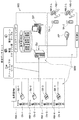
- FIG. 1 is a diagram illustrating an overall configuration of a care support system that realizes an information processing system or an information processing method according to the present embodiment.
- the care support system according to the present embodiment supports the care by watching the target person Ob by detecting the state of the monitored person (hereinafter referred to as the target person) Ob that is the object of monitoring by the corresponding sensor box SB. It has a function.
- the sensor box SB preferably has limited computer resources.
- Such a care support system MS includes, for example, as shown in FIG. 1, a sensor box SB (SB-1 to SB-4), a management server SV, and a fixed terminal device SP respectively provided in the subject person's room.
- mobile terminals TA (TA-1, TA-2) managed by caregivers, which are wired and wireless, such as LAN (Local Area Network), telephone network and data communication network ( Network, communication line) are communicably connected via NW.
- the network NW may be provided with relays such as repeaters, bridges, routers, and cross-connects that relay communication signals.
- relays such as repeaters, bridges, routers, and cross-connects that relay communication signals.
- the plurality of sensor boxes SB-1 to SB-4, the management server SV, the fixed terminal device SP, and the plurality of portable terminals TA-1 and TA-2 are connected to a wireless LAN (including an access point AP (for example, a LAN conforming to the IEEE 802.11 standard) is connected to be communicable with each other via an NW.
- the sensor box SB corresponds to an example of an electronic device.
- the target person Ob is, for example, a person who needs nursing due to illness or injury, a person who needs care due to a decrease in physical ability, or a single person living alone.
- the subject Ob is a person who needs the detection when a predetermined inconvenient event such as an abnormal state occurs in the person.
- the care support system MS is suitably arranged in a building such as a hospital, a welfare facility for the elderly, and a dwelling unit according to the type of the subject Ob.
- the care support system MS is disposed in a building of a care facility including a plurality of rooms RM in which a plurality of target persons Ob move, and a plurality of rooms such as a nurse station ST.
- the management server SV has a communication function for communicating independently with the sensor box SB, the fixed terminal SP, and the mobile terminal TA via the network NW.
- the management server SV has a function of receiving information from the sensor box SB and providing information to the mobile terminal TA and / or the fixed terminal device SP of the caregiver in charge of the room where the event has occurred, and the sensor box SB.
- -1 has a function of providing a recovery data set (recovery information) necessary for the sensor box SB in the event of a failure.
- the management server SV has a database DB as shown in FIG.
- the database DB records information relating to the failure of the sensor box SB-1 (including information relating to failure history, usage history, and usage environment for each sensor box model). Information on the failure is updated each time a report log (details will be described later) is transmitted from each sensor box SB to the management server SV.
- the management server SV can extract an optimal restoration data set for each sensor box SB from the database DB.
- a recovery data set includes firmware and tools corresponding to the sensor box SB, a recovery script group indicating a procedure up to recovery, and a recovery pattern table.
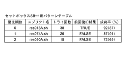
- FIG. 2 is an example of a pattern table for the sensor box SB-1.
- the priority order to be applied the name of the script, the number of recovery tries, the previous recovery result (TRUE if successful, FALSE if failed), and the success rate from recovery are listed. Is shown.
- the priority order of the pattern table is ascending order from the highest recovery success rate.
- the script name preferably corresponds to a bundled recovery script group.
- the parentheses in the success rate are the total success rates that have been successfully recovered from the failure of the sensor boxes SB-1 and SB-2 of the same model.
- the contents of the pattern table are not limited to the above, and it is sufficient that at least the priority order is associated with the script name.
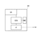
- FIG. 3 is a block diagram of the sensor box SB.
- the sensor box SB is disposed on the ceiling or wall of the living room RM of the subject Ob, and has a communication function for communicating with the management server SV or the like via the network NW. More specifically, the sensor box SB includes, for example, a camera CA, a memory MR that stores firmware, tools, and the like, a communication unit IF, and a control unit CPU that controls them.
- the sensor boxes SB-1 and SB-2 shown in FIG. 1 are the same model as each other but different from the sensor boxes SB-3 and SB-4. However, the sensor boxes SB-1 and SB-2 are assumed to have different versions of firmware.
- the control unit CPU which operates by executing a program stored in the memory MR, takes an image of the subject Ob with the camera CA, determines from the image the subject Ob's getting up, getting out of bed, falling, falling, etc. Corresponding target person information is transmitted from the communication unit IF to the management server SV via the network NW.
- the control unit CPU repeatedly performs diagnosis (also referred to as a health check) on the sensor box SB for any failure, as described later, and if a failure has occurred, displays the failure information corresponding to the failure.
- diagnosis also referred to as a health check
- the management server SV that has received the target person information from the sensor box SB wakes up, leaves the target person Ob to the terminal TA of the caregiver NS in charge of the room in which the sensor box SB is provided, via the network NW.
- Target person information indicating that a fall, a fall or the like has occurred is transmitted, and the terminal TA displays a screen according to the target person information.
- the caregiver NS who sees such a screen can determine what has happened to the subject Ob in charge, and can therefore quickly take action such as rushing to the room.
- the sensor box SB continues to monitor the state of the subject Ob in the room regardless of day or night, it is difficult to grasp the state of the subject Ob when the sensor box SB fails. There is a risk of becoming. On the other hand, if the sensor box SB is maintained at relatively short intervals, the risk of failure can be reduced, but it takes effort and cost. Therefore, it can be said that it is desirable to perform the necessary processing immediately when it is diagnosed whether the sensor box SB is functioning normally repeatedly at a specified timing and as a result it is determined that a failure has occurred.
- FIG. 4 is a ladder chart showing processing performed when the sensor box SB-1 is diagnosed as functioning normally and it is determined that a failure has occurred as a result.
- data exchange between the management server SV and the sensor box SB-1 is shown, but the same data exchange is performed with other sensor boxes.
- the management server SV reads the latest restoration data set for the sensor box SB-1 from the database DB.
- the recovery data set is repeatedly downloaded from the management server SV to the sensor box SB-1 at a predetermined timing (c11).
- the control unit CPU of the sensor box SB-1 stores the downloaded restoration data set in the memory MR.
- the downloaded recovery data set may be overwritten on the previous recovery data set, or the previous recovery data set may be left for backup.
- step S103 the control unit CPU of the sensor box SB-1 calls the self-diagnostic program from the memory MR and executes diagnosis.
- step S104 when the control unit CPU determines that the function of each unit of the sensor box SB-1 is normal based on the diagnosis result, the flow returns to step S102.
- the control unit CPU determines whether or not communication with the management server SV is possible via the communication unit IF in subsequent step S105. To do. If it is determined that communication is possible, the control unit CPU notifies the management server SV that a failure has occurred (c12). In response to this, the management server SV reads the latest restoration data set for the sensor box SB-1 from the database DB in step S106. The read recovery data set is downloaded from the management server SV to the sensor box SB-1 (c13).
- step S107 the control unit CPU attempts a recovery process from the failure of the sensor box SB-1 based on the downloaded recovery data set.
- the downloaded recovery data set is the latest and includes, for example, the pattern table shown in FIG.
- the control unit CPU refers to the pattern table and selects the script with the highest priority (priority 0: res018A.sh in the example of FIG. 2) from the recovery script group bundled with the recovery data set. According to this, the first recovery process is performed.
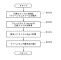
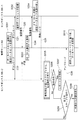
- FIG. 5 is a flowchart showing an example of a recovery process performed by the control unit CPU according to the script.
- the control unit CPU deletes unnecessary files when performing a clean installation, and in step S107b, decompresses the compressed file of the firmware (version xx) bundled with the recovery data set, and then executes step S107c. Then, the decompressed file is placed in yy, and writing of new firmware is executed in step S107d.
- the script includes, for example, restarting the sensor box. In such a case, firmware and tools are not used.
- step S108 of FIG. 4 the control unit CPU executes the self-diagnosis program again to determine whether or not the failure has been recovered. If it is determined that the failure has not yet been recovered, the control unit CPU further determines in step S111 whether or not all the scripts indicated in the pattern table have been tried. The control unit CPU that has determined that all has not been attempted returns the flow to step S107, and the next priority script (priority 1: res074A.sh in the example of FIG. 2) is included in the recovery data set. The next restoration process is performed according to this. Thereafter, in step S108 again, the control unit CPU determines whether or not the failure has been recovered.
- step S111 if it is determined that the recovery process has not been performed in spite of all the scripts being tried for the recovery process (determination Yes), it means that it is difficult to recover by itself.
- step S112 for example, recovery by an external process such as a serviceman's work is awaited. In the case of recovery by external processing, the control unit CPU advances the flow to step S109 and creates a report log to be described later.
- the report log as recovery history information includes device information (here, sensor box manufacturer name, model number, serial number, firmware version information, etc.) for identifying the sensor box SB-1 that has been recovered, History information of box SB-1 (success / failure data indicating which script failed to recover and which script was successfully recovered, operating time after recovery from previous failure, operating time after previous restart, etc. ) And usage environment information (type and specification of the network line connected to the sensor box SB-1, ambient temperature and humidity, time of failure, etc.).
- device information here, sensor box manufacturer name, model number, serial number, firmware version information, etc.
- History information of box SB-1 successes data indicating which script failed to recover and which script was successfully recovered, operating time after recovery from previous failure, operating time after previous restart, etc.
- usage environment information type and specification of the network line connected to the sensor box SB-1, ambient temperature and humidity, time of failure, etc.
- step S110 the management server SV updates the database DB based on the input report log. Specifically, based on the success / failure data in the history information, the success rate of the pattern table shown in FIG. 2 is recalculated corresponding to the sensor box SB-1. As a result, when the priority order of the script changes, the priority order is changed and stored in the database DB. Thereafter, the flow returns to step S101, and the management server SV reads the recovery data set from the latest database DB updated in this way.
- step S113 the control unit CPU reads the recovery data set downloaded immediately before the failure occurrence and stored in the memory MR, and based on the pattern table, the failure of the sensor box SB-1 is read out according to the flow of FIG. Attempt recovery from.
- step S114 the control unit CPU executes the self-diagnosis program again and determines whether or not the failure has been recovered. If it is determined that the failure has not yet been recovered, the control unit CPU further determines in step S115 whether or not all the scripts indicated in the pattern table have been tried. The control unit CPU, which has determined that all have not been attempted, returns the flow to step S113, and selects the next priority script from the recovery script group of the recovery data set stored in the memory MR. Perform recovery processing. Thereafter, in step S114 again, the control unit CPU determines whether or not the failure has been recovered.
- step S115 if it is determined that the recovery process has not been performed even though the recovery process has been attempted in accordance with all the scripts (determination Yes), it means that it is difficult to recover by itself.
- step S112 recovery by an external process such as a serviceman's work is awaited.
- the control unit CPU advances the flow to step S109 and creates the above-described report log.
- the control unit CPU of the sensor box SB-1 repeatedly receives the recovery data set from the management server SV at a specified timing and stores it in the memory MR. As a result of self-diagnosis, it is determined that a failure has occurred, and if it is determined that communication with the management server SV is impossible, recovery from the failure is performed based on the latest recovery data set stored in the memory MR. Therefore, the sensor box SB-1 can autonomously recover from the failure without relying on the management server SV.
- the sensor box SB-1 transmits a report log to the management server SV because the communication with the management server SV is possible via the network NW. Then, the database DB is updated based on the report log transmitted from the sensor box SB-1. As a result, the latest data on the success rate of the script for recovering from the failure that has occurred in the sensor box SB-1 can always be obtained.
- the sensor box SB -1 increases the possibility of autonomous recovery, saving the effort of performing recovery work through the manual operation of users, service personnel, etc., leading to cost reduction.
- the management server SV can also predict a failure that may occur in the future based on the report log transmitted from the sensor box SB-1. For example, if the management server SV recognizes that a failure is likely to occur after 72 hours or more after restarting the sensor box SB-1 based on the history information of the report log, 60 hours after restarting the sensor box SB-1 It is preferable to send an instruction (recommended information regarding recommended processing) for forcibly restarting the sensor box SB-1 to the sensor box SB-1 when the time has elapsed. In response to this, the sensor box SB-1 can suppress the occurrence of a failure by restarting (recommended processing).
- the data exchange between the management server SV and the sensor box SB-1 has been described above, but the same applies to the other sensor boxes SB-1 to SB-4.
- FIG. 6 is a ladder chart showing processing according to another embodiment.
- data exchange between the management server SV and the sensor boxes SB-1 and SB-2 is shown, and an example in which a failure occurs in the sensor box SB-2 is shown. Since the sensor box SB-2 is the same model as the sensor box SB-1, it has the same configuration as that shown in FIG. Similar data is exchanged with other sensor boxes.
- the management server SV reads the latest restoration data sets for the sensor boxes SB-1 and SB-2 from the database DB.
- the restoration data set is repeatedly downloaded at a specified timing from the management server SV to the sensor boxes SB-1 and SB-2 (c21 and c22).
- the control unit CPU of the sensor box SB-1 stores the downloaded recovery data set in the memory MR and transmits a confirmation signal to the management server SV.
- the management server SV that has received this can confirm that the sensor box SB-1 is normal.
- the control unit CPU stores the downloaded recovery data set in the memory MR and transmits a confirmation signal to the management server SV.
- the management server SV receiving this can confirm that the sensor box SB-2 is normal.
- the control unit CPU of the sensor box SB-2 repeatedly diagnoses whether or not a failure has occurred in accordance with the self-diagnosis program at a specified timing.
- the management server SV tries to send a notification that a failure has occurred (c12 in FIG. 4), but notifies the management server SV that the communication function is impaired. Has not arrived (determination Yes in step S111 in FIG. 4).
- the recovery data set is not stored in the memory MR of the sensor box SB-2 or cannot be read out, autonomous recovery becomes difficult.
- the management server SV can determine that some failure has occurred in the sensor box SB-2 (that is, the management server SV Diagnose that a failure has occurred in the sensor box SB-2). Therefore, in step S203, if the management server SV does not receive a confirmation signal from the sensor box SB-2 even after a predetermined time, the sensor box SB-2 cannot communicate with the management server SV. And a rescue signal is transmitted to the sensor box SB-1 of the same model (c24).
- the control unit CPU of the sensor box SB-1 to which the rescue signal is transmitted from the management server SV reads the latest recovery data set from the memory MR and transmits it to the sensor box SB-2 as a rescue pack in step S204.
- the rescue pack is read from the memory MR of the sensor box SB-1 by the user's hand and input to the memory MR of the sensor box SB-2. good.
- the memory MR is a removable memory card or the like, it may be removed from the sensor box SB-1 and replaced with the sensor box SB-2.
- the control unit CPU of the sensor box SB-2 reads the latest recovery data set from the rescue pack in step S205, and based on the pattern table, the sensor box SB according to the flow of FIG. -2 Try to recover from the failure.
- the pattern table of the recovery data set is as shown in FIG. 2
- the priority for applying the script is a script having a high success rate common to the sensor boxes SB-1 and SB-2 shown in parentheses. Use in the order.
- the sensor boxes SB-1 and SB-2 are of the same model, there is a possibility that the success rate from the recovery is different between the sensor box SB-1 and the sensor box SB-2, for example, when the firmware versions are different. Therefore, it is presumed that recovery is accelerated by executing the scripts in the order of the high common success rate, rather than executing the scripts in the order of the high success rate of the sensor box SB-1.
- control unit CPU of the sensor box SB-2 determines whether or not the failure has been recovered based on the self-diagnosis program in step S206. However, even if the control unit CPU of the sensor box SB-1 accesses the sensor box SB-2 and determines whether there is a failure in the sensor box SB-2 via the network using its own self-diagnosis program. good. If it is determined that the failure has not been recovered, the control unit CPU of the sensor box SB-2 further determines whether or not all the scripts shown in the pattern table have been tried in step S208. The control unit CPU, which has determined that all have not been attempted, returns the flow to step S205, selects the next priority script from the recovery script group of the recovery data set in the rescue pack, and performs the next recovery process accordingly. Do. Thereafter, in step S206 again, the control unit CPU determines whether or not the failure has been recovered.
- step S208 If it is determined in step S208 that recovery processing has been attempted in accordance with all the scripts but recovery has not been performed (determination Yes), it means that recovery using the rescue pack becomes difficult, so the control unit CPU In step S209, for example, recovery by an external process such as a serviceman's work is awaited. On the other hand, if the recovery is successful with any script, the control unit CPU creates a report log in step S207.
- the control unit CPU of the sensor box SB-2 uploads the created report log to the management server SV (c26).
- the management server SV updates the database DB based on the input report log.
- the contents of the recovery data set for the sensor box SB-2 and the recovery data set for the sensor box SB-1 are rewritten, and again from the management server SV Downloaded to the sensor boxes SB-1 and SB-2, respectively (c21, c22).
Landscapes
- Engineering & Computer Science (AREA)
- Physics & Mathematics (AREA)
- General Physics & Mathematics (AREA)
- Theoretical Computer Science (AREA)
- Computer Security & Cryptography (AREA)
- Computer Networks & Wireless Communication (AREA)
- Signal Processing (AREA)
- Quality & Reliability (AREA)
- General Engineering & Computer Science (AREA)
- Debugging And Monitoring (AREA)
- Telephonic Communication Services (AREA)
Abstract
管理サーバと通信可能な電子機器に種々の障害が生じた場合に、効率良く復旧できる情報処理システム及び情報処理方法を提供する。センサボックスSB-1の制御部CPUが、規定のタイミングで繰り返し管理サーバSVから復旧データセットを受信して、メモリMRに記憶するようになっており、更に制御部CPUが自己診断した結果、障害が生じていると判断し、また管理サーバSVと通信不能であると判断した場合には、メモリMRに記憶された最新の復旧データセットに基づいて、障害からの復旧を試みるようにしているので、管理サーバSVに頼ることなくセンサボックスSB-1が自律的に障害から復旧することができる。更に、障害からの復旧に成功した後には,ネットワークNWを介して管理サーバSVと通信可能となっているので、センサボックスSB-1は、レポートログを管理サーバSVに送信し、管理サーバSVは、センサボックスSB-1から送信されたレポートログに基づいてデータベースDBを更新する。これにより、センサボックスSB-1に生じた障害から復旧させるためのスプリクトの成功率について、常に最新のデータを入手できるから、その復旧データセットを規定のタイミングで繰り返しダウンロードすることで、センサボックスSB-1が自律的に復旧する可能性が高まり、ユーザーやサービスマン等の人手を介して復旧作業を行う手間が省け、コスト削減につながる。
Description
本発明は、電子機器の復旧を効率良く行える情報処理システム及び情報処理方法に関する。
監視カメラや小売店の電子レジスタなど、種々の電子機器がネットワークを介して管理サーバに接続されて情報のやりとりを行い、情報の集中管理が行われている。このような電子機器の使用中に何らかの障害が生じると、情報の集中管理を行えなくなるため迅速な復旧が望まれる。障害からの復旧の初動としては、電子機器を使用するユーザーが、取扱説明書等に従って復旧作業を行うことが多い。障害が比較的軽度であれば、復旧作業として再起動等を行うことで不具合のあるデータなどがリセットされ、容易に復旧を行うことができることもある。これに対し、障害が比較的重度であると、電子機器の復旧作業に不慣れなユーザーでは、復旧に手間取ることもある。そのような場合、障害の生じた電子機器のある現地にサービスマン等を派遣して復旧作業を行わせる必要があるが、それにより復旧までに多大なコストと時間がかかる。
特許文献1には、親機と子機とを接続可能な無線テレメータシステムが開示されている。特許文献1によれば、例えば親機又は子機に対して落雷等のトラブルが発生して、その回路基板等の故障が発生した場合、復旧のために、故障した親機又は子機の回路基板等から必要情報を読み出そうとしても、回路基板自体が動作しないため読み出せないことが多いとされる。かかる場合には、まず、回路基板を部品交換して復旧を行う必要があるが、交換された新たな回路基板等に記憶させるバックアップとしての必要情報を、予め外部機器に記憶しておき、ネットワークを介して親機又は子機に読み出すことはできる。しかしながら、バックアップのための専用の外部機器を設けることはコストがかかり、また常に外部機器と通信可能な状態が確保されるとは限らない。そこで、予め必要情報を親機又は子機の不揮発性メモリに記録しておき、故障が生じた場合、故障した親機又は子機から不揮発性メモリを取り外して、修理した親機又は子機に装着することで、バックアップを確保することなく、また外部機器との通信が不能であっても無線テレメータシステムの復旧を可能とすることが示されている。
しかしながら、特許文献1の技術により復旧作業が容易になるとしても、復旧に際しては依然として電子機器に対して人手を介した作業を行う必要があり、手間がかかる。又、電子機器によっては、不揮発性メモリの交換だけでは復旧が困難な場合もある。これに対し、例えば管理サーバからネットワークを介して、障害が生じた電子機器を遠隔操作して障害からの復旧を行わせる技術も開発されている。障害の発生は、ネットワークを介してなされる電子機器からの通知によって管理サーバに知らせることができるので、通知を受けた管理サーバは直ちに必要な処理を行えるから、迅速且つ効率良く電子機器の復旧を行える。しかしながら、電子機器の通信に関わる部位に障害が生じた場合、管理サーバに通知することができないから、電子機器の遠隔操作も不可能になる。
更に、同種の電子機器であっても、製造時期に応じて異なるバージョンのファームウエア等を搭載していることがあるが、それにより障害の内容が変わってくる恐れがある。障害の内容が変われば復旧の手順なども変わるので、全ての障害に対して画一化した処理により復旧を行うことは困難といえる。従って、電子機器に生じる種々の障害に対して、いかに効率良く且つ自律的に復旧させることができるかが大きな課題となっている。
本発明は、上記事情に鑑みなされたものであり、管理サーバと通信可能な電子機器に種々の障害が生じた場合に、効率良く復旧できる情報処理システム及び情報処理方法を提供することを目的とする。
上述した目的のうち少なくとも一つを実現するために、本発明の一側面を反映した情報処理システムは、
障害が発生しているか否か診断の対象となる電子機器と、
前記電子機器と通信可能に接続され、前記電子機器に障害が生じたことを前記電子機器との間の通信を介して認識する管理サーバと、を有する情報処理システムであって、
前記管理サーバは、前記電子機器における障害からの復旧に関する復旧情報を含むデータベースを有しており、
前記電子機器は、規定のタイミングで繰り返し前記管理サーバから前記復旧情報を受信して、メモリに記憶するようになっており、
前記電子機器の診断の結果、障害が生じていると判断した場合、前記電子機器は、前記メモリに記憶された最新の前記復旧情報に基づいて、前記障害からの復旧を試みるようにしており、
前記復旧を試みた後に、前記電子機器は、前記復旧に関する復旧履歴情報を前記管理サーバに送信し、
前記管理サーバは、前記電子機器から送信された前記復旧履歴情報に基づいて、前記データベースを更新するものである。
障害が発生しているか否か診断の対象となる電子機器と、
前記電子機器と通信可能に接続され、前記電子機器に障害が生じたことを前記電子機器との間の通信を介して認識する管理サーバと、を有する情報処理システムであって、
前記管理サーバは、前記電子機器における障害からの復旧に関する復旧情報を含むデータベースを有しており、
前記電子機器は、規定のタイミングで繰り返し前記管理サーバから前記復旧情報を受信して、メモリに記憶するようになっており、
前記電子機器の診断の結果、障害が生じていると判断した場合、前記電子機器は、前記メモリに記憶された最新の前記復旧情報に基づいて、前記障害からの復旧を試みるようにしており、
前記復旧を試みた後に、前記電子機器は、前記復旧に関する復旧履歴情報を前記管理サーバに送信し、
前記管理サーバは、前記電子機器から送信された前記復旧履歴情報に基づいて、前記データベースを更新するものである。
上述した目的のうち少なくとも一つを実現するために、本発明の一側面を反映した情報処理方法は、障害が発生しているか否か診断の対象となる電子機器と、前記電子機器と通信可能に接続され、前記電子機器に障害が生じたことを前記電子機器との間の通信を介して認識する管理サーバとを連係して動作させる情報処理方法であって、
前記管理サーバは、前記電子機器における障害からの復旧に関する復旧情報を含むデータベースを有しており、
前記電子機器に、規定のタイミングで繰り返し前記管理サーバから前記復旧情報を受信させて、メモリに記憶させ、
前記電子機器の診断の結果、障害が生じていると判断した場合には、前記電子機器に、前記メモリに記憶された最新の前記復旧情報に基づいて、前記障害からの復旧を試みるようにさせ、
前記復旧を試みた後に、前記電子機器から、前記復旧に関する復旧履歴情報を前記管理サーバに送信させ、
前記管理サーバに、前記電子機器から送信された前記復旧履歴情報に基づいて、前記データベースを更新させるものである。
前記管理サーバは、前記電子機器における障害からの復旧に関する復旧情報を含むデータベースを有しており、
前記電子機器に、規定のタイミングで繰り返し前記管理サーバから前記復旧情報を受信させて、メモリに記憶させ、
前記電子機器の診断の結果、障害が生じていると判断した場合には、前記電子機器に、前記メモリに記憶された最新の前記復旧情報に基づいて、前記障害からの復旧を試みるようにさせ、
前記復旧を試みた後に、前記電子機器から、前記復旧に関する復旧履歴情報を前記管理サーバに送信させ、
前記管理サーバに、前記電子機器から送信された前記復旧履歴情報に基づいて、前記データベースを更新させるものである。
本発明によれば、管理サーバと通信可能な電子機器に種々の障害が生じた場合に、効率良く復旧できる情報処理システム及び情報処理方法を提供することができる。
以下、本発明にかかる実施形態を図面に基づいて説明する。図1は、本実施形態における情報処理システム又は情報処理方法を実現する介護支援システムの全体構成を示す図である。本実施形態における介護支援システムは、見守り対象である被監視者(以下、対象者という)Obの状態を、それぞれ対応するセンサボックスSBにより検知することで対象者Obを見守って、介護を支援する機能を有するものである。尚、センサボックスSBは、限られたコンピュータ資源を持つものであると好ましい。
このような介護支援システムMSは、例えば、図1に示すように、対象者の居室にそれぞれ備えられたセンサボックスSB(SB-1~SB-4)と、管理サーバSVと、固定端末装置SPと、介護士がそれぞれ管理する携帯端末TA(TA-1、TA-2)とを有し、これらは、有線や無線で、LAN(Local Area Network)、電話網およびデータ通信網等の網(ネットワーク、通信回線)NWを介して通信可能に接続されている。ネットワークNWには、通信信号を中継する例えばリピーター、ブリッジ、ルーターおよびクロスコネクト等の中継機が備えられても良い。図1に示す例では、これら複数のセンサボックスSB-1~SB-4、管理サーバSV、固定端末装置SPおよび複数の携帯端末TA-1、TA-2は、アクセスポイントAPを含む無線LAN(例えばIEEE802.11規格に従ったLAN等)NWによって互いに通信可能に接続されている。センサボックスSBは、電子機器の一例に相当する。
対象者Obは、例えば、病気や怪我等によって看護を必要とする者や、身体能力の低下等によって介護を必要とする者や、一人暮らしの独居者等である。特に、早期発見と早期対処とを可能にする観点から、対象者Obは、例えば異常状態等の所定の不都合な事象がその者に生じた場合にその発見を必要としている者であることが好ましい。このため、介護支援システムMSは、対象者Obの種類に応じて、病院、老人福祉施設および住戸等の建物に好適に配設される。図1に示す例では、介護支援システムMSは、複数の対象者Obが入居する複数の居室RMや、ナースステーションST等の複数の部屋を備える介護施設の建物に配設されている。
管理サーバSVは、ネットワークNWを介してセンサボックスSBと、固定端末SPと、携帯端末TAとに独立して通信する通信機能を備えている。管理サーバSVは、センサボックスSBから通知を受けて、イベントが生じた居室を担当する介護士の持つ携帯端末TA、及び/又は固定端末装置SPに情報を提供する機能を有すると共に、センサボックスSB-1の障害に際し、センサボックスSBに必要な復旧データセット(復旧情報)を提供する機能を有する。
更に管理サーバSVは、図1に示すようにデータベースDBを有している。データベースDBは、センサボックスSB-1の障害に関する情報(センサボックスの機種毎の故障履歴、利用履歴、使用環境に関する情報を含む)を記録している。障害に関する情報は、各センサボックスSBからレポートログ(詳細は後述)が管理サーバSVに送信される度に更新される。管理サーバSVは、データベースDB内から、センサボックスSB毎に最適な復旧データセットを抽出できる。かかる復旧データセットは、センサボックスSBに応じたファームウェアとツール、復旧までの手順を示す復旧スクリプト群、復旧パターンテーブルを含んでいる。
図2は、センサボックスSB-1用のパターンテーブルの一例である。パターンテーブルには、図2に示すように、適用する優先順位、スプリクト名、復旧トライ回数、前回復旧結果(成功であればTRUE、失敗であればFALSE)、復旧からの成功率がリストとなって示されている。パターンテーブルの優先順位は、復旧の成功率が高い順に昇順となっている。スプリクト名は、同梱された復旧スクリプト群に対応するものであると好ましい。尚、成功率の括弧内は、同機種であるセンサボックスSB-1,SB-2の障害から復旧に成功したトータルの成功率である。パターンテーブルの内容は以上に限られず、少なくとも優先順位とスプリクト名とが対応づけられていれば足りる。
図3は、センサボックスSBのブロック図である。センサボックスSBは、対象者Obの居室RMの天井や壁等にそれぞれ配置され、ネットワークNWを介して管理サーバSV等と通信する通信機能を備えている。より具体的に、センサボックスSBは、例えばカメラCAと、ファームウェアやツールなどを記憶したメモリMRと、通信部IFと、これらを司る制御部CPUとを備えている。尚、図1で示すセンサボックスSB-1,SB-2は互いに同機種であって、センサボックスSB-3,SB-4と異なる機種である。但し、センサボックスSB-1,SB-2は異なるバージョンのファームウェアを有するものとする。
メモリMRに格納されたプログラムを実行することで動作する制御部CPUは、カメラCAで対象者Obを撮影して、その画像から対象者Obの起床、離床、転倒、転落等を判別し、それに対応する対象者情報を、通信部IFからネットワークNWを介して管理サーバSVに送信する機能を有する。又、制御部CPUは、後述するように規定のタイミングで繰り返し、センサボックスSBに障害が生じていないか診断(ヘルスチェックともいう)を行い、障害が生じていた場合、それに対応する障害情報を、同様にネットワークNWを介して管理サーバSVに送信する機能も有する。
センサボックスSBから対象者情報を受信した管理サーバSVは、ネットワークNWを介して、そのセンサボックスSBが備えられた部屋を担当する介護士NSの持つ端末TAに、対象者Obの起床、離床、転倒、転落等が生じた旨の対象者情報を送信し、かかる端末TAは、対象者情報に応じて画面表示を行うようになっている。かかる画面を見た介護士NSは、担当する対象者Obに何が生じたのか判断できるので、部屋に駆けつけるなどの対応を迅速に行うことができる。
このように、センサボックスSBは、部屋にいる対象者Obの状態を、昼夜を問わず監視し続けるものであるので、センサボックスSBに障害が生じた場合、対象者Obの状態の把握が困難となる恐れがある。一方、センサボックスSBを比較的短期間毎にメンテナンスすれば、障害が生じる恐れを低下させることはできるが、手間とコストがかかる。そこで、規定のタイミングで繰り返し、センサボックスSBが正常に機能しているかを診断し、その結果障害が生じたと判断した場合には、直ちに必要な処理を行うことが望ましいといえる。
図4は、センサボックスSB-1が正常に機能しているかを診断し、その結果障害が生じたと判断した場合に行う処理を示す梯子チャートである。ここでは、管理サーバSVとセンサボックスSB-1とのデータのやりとりを示しているが、その他のセンサボックスとも同様なデータのやりとりが行われる。
まず図4のステップS101において、管理サーバSVは、データベースDBからセンサボックスSB-1用の最新である復旧データセットを読み出す。規定のタイミングで繰り返し、かかる復旧データセットは管理サーバSVからセンサボックスSB-1にダウンロードされる(c11)。センサボックスSB-1の制御部CPUは、ステップS102で、ダウンロードした復旧データセットをメモリMRに記憶する。メモリMR中で、ダウンロードした復旧データセットは、それ以前の復旧データセットに上書きされても良いし、それ以前の復旧データセットをバックアップ用に残しておいても良い。
更に規定のタイミング(復旧データセットのダウンロードとは異なるタイミングでも良い)で、ステップS103で、センサボックスSB-1の制御部CPUは、メモリMRから自己診断プログラムを呼び出して診断を実行する。ステップS104で、制御部CPUが、その診断結果によりセンサボックスSB-1の各部の機能が正常であると判断した場合、フローはステップS102へと戻る。
一方、診断結果によりセンサボックスSB-1のいずれかに障害が発生したと判断した場合、制御部CPUは、続くステップS105で、通信部IFを介して管理サーバSVと通信可能か否かを判断する。通信可能と判断すれば、制御部CPUは管理サーバSVに障害が生じた旨の通知を行う(c12)。これに応じて管理サーバSVは、ステップS106で、データベースDBからセンサボックスSB-1用の最新である復旧データセットを読み出す。読み出された復旧データセットは、管理サーバSVからセンサボックスSB-1にダウンロードされる(c13)。
更に制御部CPUは、ステップS107で、ダウンロードした復旧データセットに基づいて、センサボックスSB-1の障害からの復旧処理を試みる。ダウンロードした復旧データセットは最新であり、例えば図2に示すパターンテーブルが含まれているものとする。ここで、制御部CPUは、パターンテーブルを参照し、最も優先順位が高いスプリクト(図2の例では優先順位0:res018A.sh)を、復旧データセットに同梱された復旧スプリクト群から選定し、これに従って最初の復旧処理を行う。
図5は、スプリクトに従って制御部CPUが行う復旧処理の一例を示すフローチャートである。まずステップS107aで、制御部CPUは、クリーンインストールを行う場合には不要なファイルを削除し、ステップS107bで、復旧データセットに同梱されたファームウェア(バージョンxx)の圧縮ファイルを解凍し、ステップS107cで、解凍したファイルをyyに配置し、ステップS107dで,新たなファームウェアの書き込みを実行する。尚、スプリクトとしては、例えばセンサボックスの再起動などもあるが、かかる場合、ファームウエアやツールは使用しないこととなる。
その後、図4のステップS108で、制御部CPUは,自己診断プログラムを再度実行して、障害から復旧したか否かを判断する。まだ障害から復旧していないと判断した場合、制御部CPUは、更にステップS111で、パターンテーブルに示されたスプリクト全てを試みたか否か判断する。全てを試みていないと判断した制御部CPUは、ステップS107へとフローを戻し、次の優先順位のスプリクト(図2の例では優先順位1:res074A.sh)を、復旧データセットに同梱された復旧スプリクト群から選定し、これに従って次の復旧処理を行う。その後、再びステップS108で、制御部CPUは障害から復旧したか否かを判断する。
ステップS111で、全てのスクリプトに従って復旧処理を試みたにもかかわらず、復旧が行われなかったと判断されると(判定Yes)、自力復旧が困難となることを意味するので、制御部CPUは,ステップS112で、例えばサービスマンの作業など外部処理による復旧を待つこととなる。外部処理によって復旧した場合、制御部CPUは、フローをステップS109へと進めて、後述するレポートログを作成する。
一方、いずれかのスクリプトにて復旧に成功した場合、制御部CPUはステップS109で、レポートログを作成する。復旧履歴情報としてのレポートログとは、復旧がなされたセンサボックスSB-1を特定するための機器情報(ここではセンサボックスのメーカー名、機種番号、シリアル番号、ファームウェアのバージョン情報等)と、センサボックスSB-1の履歴情報(どのスプリクトが復旧に失敗し、またどのスクリプトが復旧に成功したかを示す成否データ、前回の障害からの復旧後の稼動時間、前回の再起動後の稼働時間等)と、使用環境情報(センサボックスSB-1に接続されたネットワーク回線の種類や仕様、周囲の温度や湿度、障害が起きた時間等)を含んでいる。
その後、制御部CPUは管理サーバSVに,作成したレポートログをアップロードする(c14)。管理サーバSVは、ステップS110で、入力したレポートログに基づいてデータベースDBを更新する。具体的には、履歴情報中の成否データに基づいて、センサボックスSB-1に対応して、図2に示すパターンテーブルの成功率を計算し直す。その結果、スクリプトの優先順位が変わる場合、優先順位を入れ替えてデータベースDBに記憶する。以下、フローはステップS101へと戻り、このように更新された最新のデータベースDBから、管理サーバSVは復旧データセットを読み出すこととなる。
次に、センサボックスSB-1の制御部CPUが、ステップS105で、通信部IFを介して管理サーバSVと通信不能と判断した場合について説明する。この場合、制御部CPUは、管理サーバSVから最新の復旧データセットをダウンロードすることはできない。そこで、制御部CPUは、ステップS113で、障害発生直前にダウンロードされメモリMRに記憶されていた復旧データセットを読み出して、そのパターンテーブルに基づいて、図5のフローに従ってセンサボックスSB-1の障害からの復旧処理を試みる。
その後、ステップS114で、制御部CPUは,自己診断プログラムを再度実行して、障害から復旧したか否かを判断する。まだ障害から復旧していないと判断した場合、制御部CPUは、更にステップS115で、パターンテーブルに示されたスプリクト全てを試みたか否か判断する。全てを試みていないと判断した制御部CPUは、ステップS113へとフローを戻し、次の優先順位のスプリクトを、メモリMRに記憶された復旧データセットの復旧スプリクト群から選定し、これに従って次の復旧処理を行う。その後、再びステップS114で、制御部CPUは障害から復旧したか否かを判断する。
ステップS115で、全てのスクリプトに従って復旧処理を試みたにもかかわらず、復旧が行われなかったと判断されると(判定Yes)、自力復旧が困難となることを意味するので、制御部CPUは,ステップS112で、例えばサービスマンの作業など外部処理による復旧を待つこととなる。外部処理によって復旧した場合、制御部CPUは、フローをステップS109へと進めて、上述したレポートログを作成する。
本実施形態によれば、センサボックスSB-1の制御部CPUが、規定のタイミングで繰り返し管理サーバSVから復旧データセットを受信して、メモリMRに記憶するようになっており、更に制御部CPUが自己診断した結果、障害が生じていると判断し、また管理サーバSVと通信不能であると判断した場合には、メモリMRに記憶された最新の復旧データセットに基づいて、障害からの復旧を試みるようにしているので、管理サーバSVに頼ることなくセンサボックスSB-1が自律的に障害から復旧することができる。
更に、障害からの復旧に成功した後には,ネットワークNWを介して管理サーバSVと通信可能となっているので、センサボックスSB-1は、レポートログを管理サーバSVに送信し、管理サーバSVは、センサボックスSB-1から送信されたレポートログに基づいてデータベースDBを更新する。これにより、センサボックスSB-1に生じた障害から復旧させるためのスプリクトの成功率について、常に最新のデータを入手できるから、その復旧データセットを規定のタイミングで繰り返しダウンロードすることで、センサボックスSB-1が自律的に復旧する可能性が高まり、ユーザーやサービスマン等の人手を介して復旧作業を行う手間が省け、コスト削減につながる。
尚、管理サーバSVは、センサボックスSB-1から送信されたレポートログに基づいて、将来起こりえる障害を予測することもできる。例えば、管理サーバSVがレポートログの履歴情報に基づいて、センサボックスSB-1は再起動後に72時間以上経過すると障害が生じやすいと認識した場合、センサボックスSB-1の再起動後、60時間経過した時点でセンサボックスSB-1に強制再起動をかける指示(推奨される処理に関する推奨情報)をセンサボックスSB-1に送信すると好ましい。これに応じてセンサボックスSB-1は、再起動(推奨される処理)を実行することで、障害の発生を未然に抑制できる。以上、管理サーバSVとセンサボックスSB-1との間でのデータのやりとりを説明したが、その他のセンサボックスSB-1~SB-4でも同様である。
図6は、別な実施形態にかかる処理を示す梯子チャートである。ここでは、管理サーバSVとセンサボックスSB-1、SB-2とのデータのやりとりを示しており、センサボックスSB-2で障害が生じた例を示している。センサボックスSB-2は、センサボックスSB-1と同機種であるから、図3に示すものと同様な構成を有する。尚、その他のセンサボックスとも同様なデータのやりとりが行われる。
まず図6のステップS201において、管理サーバSVは、データベースDBからセンサボックスSB-1、SB-2用の最新である復旧データセットをそれぞれ読み出す。規定のタイミングで繰り返し、かかる復旧データセットは管理サーバSVからセンサボックスSB-1、SB-2にそれぞれダウンロードされる(c21、c22)。センサボックスSB-1の制御部CPUは、ステップS202で、ダウンロードした復旧データセットをメモリMRに記憶すると共に、管理サーバSVに確認信号を送信する。これを受信した管理サーバSVは、センサボックスSB-1が正常であることが確認できる。
一方、センサボックスSB-2が正常である場合、その制御部CPUは、ダウンロードした復旧データセットをメモリMRに記憶すると共に、管理サーバSVに確認信号を送信する。これを受信した管理サーバSVは、センサボックスSB-2が正常であることが確認できる。ところが、センサボックスSB-2に障害が生じると、復旧データセットのダウンロードや確認信号の送信を行えなくなる。
より具体的に説明すると、センサボックスSB-2の制御部CPUは、上述した実施形態と同様に、規定のタイミングで繰り返し自己診断プログラムに従い自身に障害が発生しているか否か診断する。その結果、障害が生じていると判断した場合、管理サーバSVに障害が生じた旨の通知を送信するよう試みる(図4のc12)が、通信機能が損なわれていると管理サーバSVに通知が届かない(図4のステップS111の判定Yes)。更に、センサボックスSB-2のメモリMRに復旧データセットが記憶されていない、もしくは読み出せない状態にあると、自律復旧が困難となる。
このような場合、センサボックスSB-2から管理サーバSVに確認信号も通知も送信されないこととなるので、管理サーバSVはセンサボックスSB-2に何らかの障害が生じたと判断できる(すなわち管理サーバSVはセンサボックスSB-2に障害が生じたと診断する)。そこで、ステップS203で、所定時間たっても管理サーバSVがセンサボックスSB-2から確認信号を受信しなかったときは、センサボックスSB-2が、管理サーバSVとの通信が不能となる無通信状態になっていると判定し、同機種であるセンサボックスSB-1に救援信号を送信する(c24)。
管理サーバSVから救援信号を送信されたセンサボックスSB-1の制御部CPUは、ステップS204で、メモリMRから最新の復旧データセットを読み出して、救助パックとしてセンサボックスSB-2に送信する。これは、図4のステップS112における外部からの復旧処理の一例に相当する。センサボックスSB-1、SB-2間で通信が不能である場合、ユーザーの手でセンサボックスSB-1のメモリMRから救助パックを読み出して、センサボックスSB-2のメモリMRに入力しても良い。或いは、メモリMRが取り外し可能なメモリカード等であれば、センサボックスSB-1から抜き出して、センサボックスSB-2のものと差し替えてもよい。
その救助パックを取得できたとき、センサボックスSB-2の制御部CPUは、ステップS205で救助パックから最新の復旧データセットを読み出して、そのパターンテーブルに基づいて、図5のフローに従ってセンサボックスSB-2の障害からの復旧処理を試みる。このとき、復旧データセットのパターンテーブルが図2に示すものであるとき、スプリクトを適用する優先順位としては、括弧内に示すセンサボックスSB-1,SB-2に共通である成功率が高いスプリクトの順に使用する。センサボックスSB-1,SB-2は同機種であるものの、ファームウェアのバージョンが異なる場合など、復旧からの成功率がセンサボックスSB-1とセンサボックスSB-2とで異なる可能性がある。従って、センサボックスSB-1単独の成功率が高い順にスプリクトを実行するよりも、共通の成功率が高い順にスプリクトを実行する方が、復旧が早まると推測されるからである。
その後、センサボックスSB-2の制御部CPUは,ステップS206で自己診断プログラムに基づいて障害から復旧したか否かを判断する。但し、センサボックスSB-1の制御部CPUが、センサボックスSB-2にアクセスした上で,自身の自己診断プログラムを用いてネットワークを介してセンサボックスSB-2の障害の有無を判定しても良い。まだ障害から復旧していないと判断された場合、更にステップS208で、センサボックスSB-2の制御部CPUは,パターンテーブルに示されたスプリクト全てを試みたか否か判断する。全てを試みていないと判断した制御部CPUは、ステップS205へとフローを戻し、次の優先順位のスプリクトを、救助パックにおける復旧データセットの復旧スプリクト群から選定し、これに従って次の復旧処理を行う。その後、再びステップS206で、制御部CPUは障害から復旧したか否かを判断する。
ステップS208で、全てのスクリプトに従って復旧処理を試みたにもかかわらず、復旧が行われなかったと判断されると(判定Yes)、救助パックによる復旧が困難となることを意味するので、制御部CPUは,ステップS209で、例えばサービスマンの作業など外部処理による復旧を待つこととなる。これに対し、いずれかのスクリプトにて復旧に成功した場合、制御部CPUはステップS207で、レポートログを作成する。
その後、センサボックスSB-2の制御部CPUは、管理サーバSVに,作成したレポートログをアップロードする(c26)。管理サーバSVは、ステップS210で、入力したレポートログに基づいてデータベースDBを更新する。これにより、センサボックスSB-2用の復旧データセット、及びセンサボックスSB-1用の復旧データセットの内容(パターンテーブルの括弧内に示す共通の成功率)が書き換えられて、再び管理サーバSVからセンサボックスSB-1、SB-2にそれぞれダウンロードされる(c21、c22)。
本発明は、明細書に記載の実施形態に限定されるものではなく、他の実施形態・変形例を含むことは、本明細書に記載された実施形態や技術思想から本分野の当業者にとって明らかである。明細書の記載及び実施形態は、あくまでも例証を目的としており、本発明の範囲は後述するクレームによって示されている。例えば、電子機器としてはセンサボックスの例を挙げたが、これに限らずネットワークを介して管理サーバに接続された複合機、監視カメラ、スーパーや小売店の電子レジスタ等であっても良い。
AP アクセスポイント
CA カメラ
CPU 制御部
DB データベース
IF 通信部
MR メモリ
MS 介護支援システム
NS 介護士
NW ネットワーク
Ob 対象者
RM 居室
SB-1~SB-4 センサボックス
SP 固定端末
ST ナースステーション
SV 管理サーバ
TA 携帯端末
CA カメラ
CPU 制御部
DB データベース
IF 通信部
MR メモリ
MS 介護支援システム
NS 介護士
NW ネットワーク
Ob 対象者
RM 居室
SB-1~SB-4 センサボックス
SP 固定端末
ST ナースステーション
SV 管理サーバ
TA 携帯端末
Claims (5)
- 障害が発生しているか否か診断の対象となる電子機器と、
前記電子機器と通信可能に接続され、前記電子機器に障害が生じたことを前記電子機器との間の通信を介して認識する管理サーバと、を有する情報処理システムであって、
前記管理サーバは、前記電子機器における障害からの復旧に関する復旧情報を含むデータベースを有しており、
前記電子機器は、規定のタイミングで繰り返し前記管理サーバから前記復旧情報を受信して、メモリに記憶するようになっており、
前記電子機器の診断の結果、障害が生じていると判断した場合、前記電子機器は、前記メモリに記憶された最新の前記復旧情報に基づいて、前記障害からの復旧を試みるようにしており、
前記復旧を試みた後に、前記電子機器は、前記復旧に関する復旧履歴情報を前記管理サーバに送信し、
前記管理サーバは、前記電子機器から送信された前記復旧履歴情報に基づいて、前記データベースを更新する情報処理システム。 - 前記電子機器に障害が生じていると判断された場合において、前記電子機器が前記管理サーバと通信不能なときは、前記電子機器は、前記メモリに記憶された最新の前記復旧情報に基づいて、前記障害からの復旧を試み、前記電子機器が前記管理サーバと通信可能なときは、前記電子機器は、前記管理サーバに最新の前記復旧情報を求める通知を送信し、前記管理サーバから送信された最新の前記復旧情報に基づいて、前記障害からの復旧を試みる請求項1に記載の情報処理システム。
- 前記復旧履歴情報は、前記電子機器の機器情報、前記電子機器の障害の復旧に用いた前記復旧情報とその成否を示す履歴情報、及び前記電子機器の使用環境情報を含むことを特徴とする請求項1又は2に記載の情報処理システム。
- 前記管理サーバは、前記電子機器から送信された前記復旧履歴情報に基づいて、将来起こりえる障害を予測し、前記障害を回避するために推奨される処理に関する推奨情報を前記電子機器に送信し、前記電子機器は、前記推奨情報に基づいて前記推奨される処理を実行する請求項1~3のいずれかに記載の情報処理システム。
- 障害が発生しているか否か診断の対象となる電子機器と、前記電子機器と通信可能に接続され、前記電子機器に障害が生じたことを前記電子機器との間の通信を介して認識する管理サーバとを連係して動作させる情報処理方法であって、
前記管理サーバは、前記電子機器における障害からの復旧に関する復旧情報を含むデータベースを有しており、
前記電子機器に、規定のタイミングで繰り返し前記管理サーバから前記復旧情報を受信させて、メモリに記憶させ、
前記電子機器の診断の結果、障害が生じていると判断した場合には、前記電子機器に、前記メモリに記憶された最新の前記復旧情報に基づいて、前記障害からの復旧を試みるようにさせ、
前記復旧を試みた後に、前記電子機器から、前記復旧に関する復旧履歴情報を前記管理サーバに送信させ、
前記管理サーバに、前記電子機器から送信された前記復旧履歴情報に基づいて、前記データベースを更新させる情報処理方法。
Priority Applications (1)
| Application Number | Priority Date | Filing Date | Title |
|---|---|---|---|
| JP2017565552A JP6838568B2 (ja) | 2016-02-05 | 2017-01-31 | 情報処理システム及び情報処理方法 |
Applications Claiming Priority (2)
| Application Number | Priority Date | Filing Date | Title |
|---|---|---|---|
| JP2016-020460 | 2016-02-05 | ||
| JP2016020460 | 2016-02-05 |
Publications (1)
| Publication Number | Publication Date |
|---|---|
| WO2017135226A1 true WO2017135226A1 (ja) | 2017-08-10 |
Family
ID=59500225
Family Applications (1)
| Application Number | Title | Priority Date | Filing Date |
|---|---|---|---|
| PCT/JP2017/003330 Ceased WO2017135226A1 (ja) | 2016-02-05 | 2017-01-31 | 情報処理システム及び情報処理方法 |
Country Status (2)
| Country | Link |
|---|---|
| JP (1) | JP6838568B2 (ja) |
| WO (1) | WO2017135226A1 (ja) |
Cited By (3)
| Publication number | Priority date | Publication date | Assignee | Title |
|---|---|---|---|---|
| WO2019230049A1 (ja) * | 2018-05-31 | 2019-12-05 | 太陽誘電株式会社 | 監視装置、監視方法、監視プログラム、情報処理装置、および監視システム |
| JPWO2023135699A1 (ja) * | 2022-01-13 | 2023-07-20 | ||
| US12554574B2 (en) | 2021-12-17 | 2026-02-17 | Hitachi Industrial Equipment Systems Co., Ltd. | Communication system, management device, and terminal |
Citations (6)
| Publication number | Priority date | Publication date | Assignee | Title |
|---|---|---|---|---|
| JP2001067288A (ja) * | 1999-08-27 | 2001-03-16 | Fujitsu Ltd | 障害修復機能を持つ装置、その装置を支援するサーバ装置、障害修復機能を持つシステム及びプログラム記録媒体 |
| JP2003296141A (ja) * | 2002-03-29 | 2003-10-17 | Nec Corp | 障害事前検知システム、障害事前検知方法、障害事前検知サーバ及び障害事前検知端末 |
| JP2007199976A (ja) * | 2006-01-26 | 2007-08-09 | Hitachi Information Systems Ltd | 障害予知システム及び障害予知プログラム |
| JP2008065547A (ja) * | 2006-09-06 | 2008-03-21 | Nec Fielding Ltd | サーバ運用支援システム、サーバ運用支援方法およびプログラム |
| JP2008210148A (ja) * | 2007-02-26 | 2008-09-11 | Hitachi Information Systems Ltd | 障害対応システム及び障害対応方法 |
| JP2011118575A (ja) * | 2009-12-02 | 2011-06-16 | Hitachi Ltd | 障害対策情報取得方法および管理サーバ |
Family Cites Families (2)
| Publication number | Priority date | Publication date | Assignee | Title |
|---|---|---|---|---|
| JP2000099429A (ja) * | 1998-09-25 | 2000-04-07 | Nippon Telegr & Teleph Corp <Ntt> | ネットワーク接続状態判別方法及びその装置 |
| US20060129931A1 (en) * | 2004-12-10 | 2006-06-15 | Microsoft Corporation | Integrated client help viewer for internet-based and local help content |
-
2017
- 2017-01-31 JP JP2017565552A patent/JP6838568B2/ja active Active
- 2017-01-31 WO PCT/JP2017/003330 patent/WO2017135226A1/ja not_active Ceased
Patent Citations (6)
| Publication number | Priority date | Publication date | Assignee | Title |
|---|---|---|---|---|
| JP2001067288A (ja) * | 1999-08-27 | 2001-03-16 | Fujitsu Ltd | 障害修復機能を持つ装置、その装置を支援するサーバ装置、障害修復機能を持つシステム及びプログラム記録媒体 |
| JP2003296141A (ja) * | 2002-03-29 | 2003-10-17 | Nec Corp | 障害事前検知システム、障害事前検知方法、障害事前検知サーバ及び障害事前検知端末 |
| JP2007199976A (ja) * | 2006-01-26 | 2007-08-09 | Hitachi Information Systems Ltd | 障害予知システム及び障害予知プログラム |
| JP2008065547A (ja) * | 2006-09-06 | 2008-03-21 | Nec Fielding Ltd | サーバ運用支援システム、サーバ運用支援方法およびプログラム |
| JP2008210148A (ja) * | 2007-02-26 | 2008-09-11 | Hitachi Information Systems Ltd | 障害対応システム及び障害対応方法 |
| JP2011118575A (ja) * | 2009-12-02 | 2011-06-16 | Hitachi Ltd | 障害対策情報取得方法および管理サーバ |
Cited By (5)
| Publication number | Priority date | Publication date | Assignee | Title |
|---|---|---|---|---|
| WO2019230049A1 (ja) * | 2018-05-31 | 2019-12-05 | 太陽誘電株式会社 | 監視装置、監視方法、監視プログラム、情報処理装置、および監視システム |
| JP6622948B1 (ja) * | 2018-05-31 | 2019-12-18 | 太陽誘電株式会社 | 監視装置、監視方法、監視プログラム、情報処理装置、および監視システム |
| US12554574B2 (en) | 2021-12-17 | 2026-02-17 | Hitachi Industrial Equipment Systems Co., Ltd. | Communication system, management device, and terminal |
| JPWO2023135699A1 (ja) * | 2022-01-13 | 2023-07-20 | ||
| JP7800563B2 (ja) | 2022-01-13 | 2026-01-16 | 日本電気株式会社 | 情報処理装置、情報処理方法、およびプログラム |
Also Published As
| Publication number | Publication date |
|---|---|
| JP6838568B2 (ja) | 2021-03-03 |
| JPWO2017135226A1 (ja) | 2018-11-29 |
Similar Documents
| Publication | Publication Date | Title |
|---|---|---|
| US8572600B2 (en) | Method for updating firmware of sensor nodes on the wireless sensor network | |
| JP2009260778A (ja) | センサネットワーク用ゲートウェイ、及びセンサネットワークシステム | |
| JP6838568B2 (ja) | 情報処理システム及び情報処理方法 | |
| JP2005117371A (ja) | リモート監視装置およびリモート監視システム | |
| JP4919935B2 (ja) | 警備システム | |
| JP2020088460A (ja) | 状態表示システム、通信障害特定方法、及びプログラム | |
| JP4836920B2 (ja) | ネットワーク監視システム及び端末装置 | |
| JP4639675B2 (ja) | 機器監視装置及び機器監視システム | |
| JP6950681B2 (ja) | 見守りシステム | |
| KR20110091122A (ko) | 원격 모니터링 시스템의 자동복구 장치 및 그 방법 | |
| JP2009211279A (ja) | 操業データ管理サーバシステム | |
| JP2006154991A (ja) | 情報処理システム、情報処理システムの制御方法、監視装置、監視プログラム、保守管理プログラム | |
| JP4973516B2 (ja) | ネットワーク管理システム、ネットワーク管理装置、装置管理方法及び装置管理制御プログラム | |
| JP2019096202A (ja) | 通信システム及び中継装置 | |
| JP2004088236A (ja) | 無線基地局監視システム | |
| CN118740660B (zh) | 一种边缘计算嵌入式应用依存系统 | |
| CN110659174A (zh) | 监控告警方法、装置和系统 | |
| JP2017219907A (ja) | 情報読み出し治具及び電子機器 | |
| JP7775176B2 (ja) | 監視装置、管理装置、通信システム、および復旧方法 | |
| WO2013116923A1 (en) | Robust alarm system with auxiliary processing sub-system | |
| KR20180131506A (ko) | 보안 시스템 및 방법 | |
| JP2003244150A (ja) | ネットワーク復旧システム | |
| JP7443010B2 (ja) | 防災監視設備の物件データ管理システム | |
| CN111475332B (zh) | 管理方法、结构物监视装置以及结构物监视系统 | |
| JP2024156249A (ja) | 監視制御装置、ログデータ保存方法およびデータ保存プログラム |
Legal Events
| Date | Code | Title | Description |
|---|---|---|---|
| 121 | Ep: the epo has been informed by wipo that ep was designated in this application |
Ref document number: 17747382 Country of ref document: EP Kind code of ref document: A1 |
|
| ENP | Entry into the national phase |
Ref document number: 2017565552 Country of ref document: JP Kind code of ref document: A |
|
| NENP | Non-entry into the national phase |
Ref country code: DE |
|
| 122 | Ep: pct application non-entry in european phase |
Ref document number: 17747382 Country of ref document: EP Kind code of ref document: A1 |