WO2017135059A1 - 積層体および液晶表示装置 - Google Patents
積層体および液晶表示装置 Download PDFInfo
- Publication number
- WO2017135059A1 WO2017135059A1 PCT/JP2017/001807 JP2017001807W WO2017135059A1 WO 2017135059 A1 WO2017135059 A1 WO 2017135059A1 JP 2017001807 W JP2017001807 W JP 2017001807W WO 2017135059 A1 WO2017135059 A1 WO 2017135059A1
- Authority
- WO
- WIPO (PCT)
- Prior art keywords
- transparent layer
- laminate
- layer
- liquid crystal
- film
- Prior art date
- Legal status (The legal status is an assumption and is not a legal conclusion. Google has not performed a legal analysis and makes no representation as to the accuracy of the status listed.)
- Ceased
Links
Classifications
-
- B—PERFORMING OPERATIONS; TRANSPORTING
- B32—LAYERED PRODUCTS
- B32B—LAYERED PRODUCTS, i.e. PRODUCTS BUILT-UP OF STRATA OF FLAT OR NON-FLAT, e.g. CELLULAR OR HONEYCOMB, FORM
- B32B27/00—Layered products comprising a layer of synthetic resin
- B32B27/18—Layered products comprising a layer of synthetic resin characterised by the use of special additives
-
- G—PHYSICS
- G02—OPTICS
- G02B—OPTICAL ELEMENTS, SYSTEMS OR APPARATUS
- G02B5/00—Optical elements other than lenses
- G02B5/30—Polarising elements
-
- G—PHYSICS
- G02—OPTICS
- G02F—OPTICAL DEVICES OR ARRANGEMENTS FOR THE CONTROL OF LIGHT BY MODIFICATION OF THE OPTICAL PROPERTIES OF THE MEDIA OF THE ELEMENTS INVOLVED THEREIN; NON-LINEAR OPTICS; FREQUENCY-CHANGING OF LIGHT; OPTICAL LOGIC ELEMENTS; OPTICAL ANALOGUE/DIGITAL CONVERTERS
- G02F1/00—Devices or arrangements for the control of the intensity, colour, phase, polarisation or direction of light arriving from an independent light source, e.g. switching, gating or modulating; Non-linear optics
- G02F1/01—Devices or arrangements for the control of the intensity, colour, phase, polarisation or direction of light arriving from an independent light source, e.g. switching, gating or modulating; Non-linear optics for the control of the intensity, phase, polarisation or colour
- G02F1/13—Devices or arrangements for the control of the intensity, colour, phase, polarisation or direction of light arriving from an independent light source, e.g. switching, gating or modulating; Non-linear optics for the control of the intensity, phase, polarisation or colour based on liquid crystals, e.g. single liquid crystal display cells
- G02F1/133—Constructional arrangements; Operation of liquid crystal cells; Circuit arrangements
- G02F1/1333—Constructional arrangements; Manufacturing methods
- G02F1/1335—Structural association of cells with optical devices, e.g. polarisers or reflectors
Definitions
- the present invention relates to a laminate including a polarizing layer and a liquid crystal display device.
- the polarizing plate is an essential member constituting the liquid crystal display device.
- a general polarizing plate has a configuration in which an optical film is bonded to one side or both sides of a polarizing film in which a dichroic dye such as an iodine complex is adsorbed and oriented on a polyvinyl alcohol (PVA) resin.
- PVA polyvinyl alcohol
- the polarizing plate which is an essential member of the liquid crystal display device, is also becoming thinner and larger, and the deformation of the polarizing plate is likely to cause a display failure of the panel. Specifically, when the polarizing plate expands and contracts, the liquid crystal panel attached to the polarizing plate warps, and apart from this, the backlight member and the like are also deformed, and light unevenness occurs due to the contact between the panel and the backlight member. It is considered to be.
- Patent Document 1 a method using an optical film made of an acrylic resin having a small photoelastic coefficient (Patent Document 1) has been proposed.
- Patent Document 2 a retardation film and polarizing plate
- Patent Document 3 a retardation film containing a styrene resin and a large retardation
- Patent Document 4 a pressure-sensitive adhesive which is used for adhesion between a polarizing plate and a glass substrate and is effective in suppressing failure of a liquid crystal panel due to static electricity, has been proposed.
- the acrylic film disclosed in Patent Document 1 and the acrylic / styrene film disclosed in Patent Document 2 are adhesive to the polarizing layer (also referred to as “polarizing film” or “polarizer”).
- polarizing film also referred to as “polarizing film” or “polarizer”.
- the styrene film disclosed in Patent Document 3 has low brittleness, and it is necessary to increase the film thickness in order to ensure strength. For this reason, it has been found that it is difficult to lower the retardation, and the display performance is deteriorated.
- the laminate in which the pressure-sensitive adhesive composition containing the antistatic agent disclosed in Patent Document 4 is in direct contact with the polarizing film has excellent light unevenness performance due to environmental changes, It was found that the degree of change in the degree of polarization when stored under humidity was large and the reliability was poor.
- the problem to be solved by the present invention is to provide a laminated body that has excellent reliability and can suppress uneven light of the liquid crystal display device due to environmental changes when mounted on the liquid crystal display device with high yield.
- a transparent layer having a specific film thickness and a low transmission coefficient of the antistatic agent is disposed between the polarizing layer and the layer containing the antistatic agent.
- the equilibrium moisture absorption rate and moisture permeability of the transparent layer are controlled to a specific relationship, such as controlling the transparent layer to a specific equilibrium moisture absorption rate.
- the inventors have found that it is effective to control the moisture permeability to a specific level. This is presumed to reduce the permeation coefficient of the antistatic agent by controlling the dissolution phenomenon of the antistatic agent in the transparent layer and the diffusion phenomenon in the transparent layer.
- the transmission coefficient of the antistatic agent When the transmission coefficient of the antistatic agent is lowered in this way, the hydrophobicity of the transparent layer increases, and the productivity of the laminate may be significantly reduced when the polarizing layer and the transparent layer are laminated with an adhesive. is there.
- the productivity of the laminate By controlling the water vapor transmission rate of the transparent layer to a specific value or more, the productivity of the laminate can be improved, and both the suppression of the transmission coefficient of the antistatic agent can be achieved.
- the present invention which is a specific means for solving the above-described problems is as follows.
- ⁇ 1> A laminate in which at least a polarizing layer, an adhesive layer, a transparent layer, and a layer containing an antistatic agent are arranged in this order, The film thickness of the transparent layer is 0.1 to 10 ⁇ m, A laminate in which the migration rate of the antistatic agent after wet heat is 0 to 30%.
- ⁇ 2> The laminate according to ⁇ 1>, wherein the migration rate of the antistatic agent after wet heat thermostat is 0.01 to 30%.
- ⁇ 3> The laminate according to ⁇ 1> or ⁇ 2>, wherein the transparent layer has an equilibrium moisture absorption rate of 2.0% by mass or less.
- ⁇ 4> The laminate according to any one of ⁇ 1> to ⁇ 3>, wherein the moisture permeability in terms of 5 ⁇ m of the transparent layer is 200 to 5000 g / m 2 / day.
- ⁇ 5> The laminate according to any one of ⁇ 1> to ⁇ 4>, wherein the transparent layer contains a fluorine compound and / or a silicon compound.
- ⁇ 6> The laminate according to any one of ⁇ 1> to ⁇ 5>, wherein the transparent layer contains a styrene resin.
- ⁇ 7> The laminate according to any one of ⁇ 1> to ⁇ 6>, wherein the in-plane retardation Re of the transparent layer at a wavelength of 590 nm is 0 to 20 nm and the thickness direction retardation Rth at a wavelength of 590 nm is ⁇ 25 to 25 nm. . ⁇ 8>
- the transparent layer is a transparent layer composed of two or more layers.
- the antistatic agent contains an organic cation compound.
- ⁇ 10> The laminate according to any one of ⁇ 1> to ⁇ 9>, wherein the content of the antistatic agent is 0.01 to 10% by mass with respect to the composition of the layer containing the antistatic agent.
- ⁇ 11> The laminate according to any one of ⁇ 1> to ⁇ 10>, wherein the polarizing layer contains an iodine-polyvinyl alcohol complex.
- ⁇ 12> A liquid crystal display device comprising a liquid crystal cell and the laminate according to any one of ⁇ 1> to ⁇ 11>.
- ⁇ 13> The liquid crystal display device according to ⁇ 12>, wherein the transparent layer is disposed between the polarizing layer and the liquid crystal cell.
- ⁇ 14> The liquid crystal display device according to ⁇ 12> or ⁇ 13>, further including a backlight, wherein the laminate is disposed on the backlight side.
- ⁇ 15> The liquid crystal display device according to ⁇ 12> or ⁇ 13>, further including a backlight, wherein the laminate is disposed on the viewing side.
- ⁇ 16> The liquid crystal display device according to any one of ⁇ 12> to ⁇ 15>, wherein the liquid crystal cell is an IPS system.
- the film thickness of the transparent layer is 0.1 to 10 ⁇ m
- the transparent layer has an equilibrium moisture absorption of 2.0% by mass or less, and a moisture permeability of 5 to 5 ⁇ m is 200 to 5000 g / m 2 / day,
- the present invention it is possible to provide a stacked body that is excellent in reliability and can suppress unevenness of light in a liquid crystal display device due to environmental changes when mounted on the liquid crystal display device with a high yield.
- the transparent layer preferably has a total light transmittance of visible light (wavelength of 380 to 780 nm) of 80% or more, more preferably 85% or more, and further preferably 90% or more.
- the migration rate of the antistatic agent contained in the layer containing the antistatic agent of the present invention after the wet heat thermometer is 1 mm thick on the side opposite to the transparent layer of the layer containing the antistatic agent of the laminate of the present invention.
- a test piece adjacent to an alkali-free glass is prepared and held for 3 days in an environment of 85 ° C. and a relative humidity of 85%, and then held for 24 hours in an environment of 25 ° C. and a relative humidity of 60%. Thereafter, the laminate is taken out, and a cross-sectional piece sample of the laminate is prepared with a microtome.
- the cross-sectional profile of the antistatic agent amount of the cross-sectional piece sample was measured by TOF-SIMS, and the integrated value (A2) of the antistatic agent amount transferred to the polarizing film side from the transparent layer of the present invention and the antistatic agent were determined. It can be calculated by the ratio (A2 / A1 ⁇ 100) to the integral value (A1) of the layer to be contained. Further, the antistatic agent and the layer having the antistatic agent are extracted with a solvent that swells or dissolves, and the ratio of the extracted antistatic agent amount (B2) to the antistatic agent amount before wet heat treatment (B1) ( (B2 / B1 ⁇ 100).
- the value calculated using the former method is defined as the migration rate after the wet heat thermostat.
- the migration rate of the antistatic agent of the present invention is 0 to 30%, preferably 0.01 to 30%, more preferably 0.1 to 25%, still more preferably 0.5 to 20%. If it is this range, durability of a polarizing layer and adhesiveness of a polarizing layer and a transparent layer can be made compatible.
- the relationship between the equilibrium moisture absorption rate of the transparent layer and the value obtained by dividing the moisture permeability by the equilibrium moisture absorption rate is controlled. It is effective to do.
- the equilibrium moisture absorption of the transparent layer of the present invention controls the permeation coefficient of the antistatic agent, so that the equilibrium moisture absorption at 25 ° C. and 80% relative humidity is 0 to 2.0 mass% regardless of the film thickness. It is preferable that The content is more preferably 0 to 1.0% by mass, and further preferably 0.01 to 0.5% by mass. An equilibrium moisture absorption of 2.0% by mass or less is preferable from the viewpoint of suppressing the dissolution phenomenon of the antistatic agent in the transparent layer. In the present specification, the equilibrium moisture absorption rate of the transparent layer can be measured using a sample having an increased film thickness as necessary.
- the sample was conditioned for 24 hours or more, and then measured by the Karl Fischer method using a moisture measuring device and sample drying apparatuses “CA-03” and “VA-05” (both manufactured by Mitsubishi Chemical Corporation). It was calculated by dividing the amount of water (g) by the sample mass (g).
- the moisture permeability of the transparent layer of the present invention is measured under the conditions of 40 ° C. and 90% RH based on JIS Z-0208.
- the water vapor transmission rate of a transparent layer can be measured with a film having a large thickness so that self-supporting property can be maintained as necessary.
- the obtained moisture permeability was divided by the thickness (unit: ⁇ m) of the film used for the measurement, and the value calculated by multiplying by 5 was taken as the moisture permeability converted to 5 ⁇ m.
- the moisture permeability of the transparent layer of the present invention is not particularly limited, but the moisture permeability converted to 5 ⁇ m is preferably 200 to 5000 g / m 2 / day.
- the moisture permeability is 500 to 3000 g / m 2 / day, and particularly preferably 700 to 2000 g / m 2 / day. If the moisture permeability is within this range, it is preferable because both the workability of the polarizing plate and the durability of the polarizing plate against humidity or wet heat can be achieved. In addition, when it is difficult to produce a film capable of maintaining the self-supporting property, the transparent layer of the present invention can be formed on an appropriate support having a known moisture permeability, and the change can be obtained from the moisture permeability change.
- ⁇ Value obtained by dividing moisture permeability by equilibrium moisture absorption rate> In order to ensure the transfer rate of the antistatic agent after wet heat and the adhesion between the polarizing layer and the transparent layer, a value obtained by dividing the moisture permeability in terms of the above-mentioned equilibrium moisture absorption rate by 5 ⁇ m by the equilibrium moisture absorption rate. 500 to 100,000, preferably 2,000 to 50,000, more preferably 5,000 to 35,000. Within this range, the polarizing plate processability and the durability of the polarizing plate with respect to humidity or wet heat can both be achieved, which is preferable.
- the transparent layer used in the laminate of the present invention preferably has an absolute value of the photoelastic coefficient C of 2 ⁇ 10 ⁇ 12 Pa ⁇ 1 or more, preferably 2 ⁇ 10 ⁇ 12 Pa ⁇ 1 to 100 ⁇ 10 ⁇ 12 Pa ⁇ 1. More preferably, 4 ⁇ 10 ⁇ 12 Pa ⁇ 1 to 15 ⁇ 10 ⁇ 12 Pa ⁇ 1 is still more preferable, and 5 ⁇ 10 ⁇ 12 Pa ⁇ 1 to 12 ⁇ 10 ⁇ 12 Pa ⁇ 1 is most preferable.
- the absolute value of the photoelastic coefficient of the transparent layer By setting the absolute value of the photoelastic coefficient of the transparent layer to 2 ⁇ 10 ⁇ 12 Pa ⁇ 1 or more, it becomes possible to suppress deformation failure and secure adhesiveness with the polarizing layer, and 100 ⁇ 10 ⁇ 12 Pa ⁇ 1 or less. Thus, retardation change due to stress birefringence can be offset by orientation birefringence without impairing display characteristics, and retardation stability in a laminate state can be imparted.
- the photoelastic coefficient can be controlled by appropriately selecting materials and using two or more materials in combination as necessary. In the transparent layer, the absolute value of the photoelastic coefficient only needs to satisfy the above range in any at least one direction in the plane.
- the photoelastic coefficient of the transparent layer can be measured using a film having a large thickness so that self-supporting property can be maintained as necessary.
- the photoelastic coefficient of the film was measured by cutting the film in a size of 5 cm ⁇ 1 cm so that the measurement direction would be the longitudinal direction of the film, adjusting the humidity for 2 hours at 25 ° C.
- orientation birefringence In the transparent layer used in the laminate of the present invention, the sign of orientation birefringence is preferably opposite to the sign of the photoelastic coefficient, and the stress birefringence and orientation birefringence generated in the laminate state are offset as described above. It is preferable to suppress retardation changes accompanying environmental changes.
- the sign of orientation birefringence can be controlled by appropriately selecting a material and using two or more materials in combination as necessary.
- orientation birefringence (retardation described later) within a range that does not impair the above-described stress birefringence and impair display characteristics. For example, heating or stretching before and after laminating a transparent layer and a polarizing layer.
- the sign of orientation birefringence is a slow axis direction when a free-end uniaxial stretching is performed at a glass transition temperature, which will be described later, using a film whose thickness is increased so that self-supporting property can be maintained if necessary. If the slow axis is parallel to the stretching direction, it is positive birefringence, and if it is orthogonal, it is negative birefringence.
- the film thickness of the transparent layer used in the laminate of the present invention is 0.1 to 10 ⁇ m, preferably 0.5 to 7.0 ⁇ m, more preferably 1.0 to 5.0 ⁇ m, and 1.5 to 4. 0 ⁇ m is more preferable.
- the film thickness is 0.1 to 10 ⁇ m, preferably 0.5 to 7.0 ⁇ m, more preferably 1.0 to 5.0 ⁇ m, and 1.5 to 4. 0 ⁇ m is more preferable.
- a preferable retardation range can be obtained.
- an effect of reducing light unevenness of the liquid crystal display device accompanying a change in environment and an effect of reducing the warpage of the liquid crystal panel accompanying a change in temperature and humidity can be expected.
- Re and Rth represent in-plane retardation and retardation in the thickness direction at a wavelength of 590 nm, respectively.
- Re and Rth are values measured at a wavelength of 590 nm in AxoScan OPMF-1 (manufactured by Optoscience).
- AxoScan OPMF-1 manufactured by Optoscience.
- the retardation of the transparent layer used in the laminate of the present invention is not particularly limited, but when used in an IPS mode liquid crystal display device, Re is preferably 0 to 20 nm, more preferably 0 to 10 nm, and further preferably 0 to 5 nm. .
- the Rth of the transparent layer used in the laminate of the present invention is preferably ⁇ 25 to 25 nm, more preferably ⁇ 20 to 5 nm, and further preferably ⁇ 10 to 0 nm.
- the humidity dependency ( ⁇ Re) of Re of the transparent layer used in the laminate of the present invention is not particularly limited, but is preferably ⁇ 20 to 20 nm, more preferably ⁇ 10 to 10 nm, and further preferably ⁇ 5 to 5 nm.
- the humidity dependency ( ⁇ Rth) of Rth of the transparent layer used in the laminate of the present invention is preferably 20 nm or less ( ⁇ 20 to 20 nm) in absolute value, more preferably ⁇ 15 to 15 nm, ⁇ 10 to 10 nm is more preferable, and ⁇ 5 to 5 nm is most preferable.
- Re (H%) and Rth (H%) are the humidity of the transparent layer at 25 ° C. and relative humidity (H%) for 24 hours, and the relative humidity at H% according to the above-described retardation measurement method.
- the retardation value is measured and calculated.
- Re (H%) and Rth (H%) are the humidity of the transparent layer at 25 ° C. and relative humidity (H%) for 24 hours, and the relative humidity at H% according to the above-described retardation measurement method.
- the retardation value is measured and calculated.
- Re when only Re is described without specifying the relative humidity, it is a value measured at a relative humidity of 60%. Unless otherwise specified, the value is at a wavelength
- the elastic modulus of the transparent layer used in the laminate of the present invention is not particularly limited, but is preferably 1.0 to 3.5 GPa, more preferably 1.5 to 3.3 GPa, and further 2.0 to 3.0 GPa. preferable.
- the elastic modulus (tensile elastic modulus) of the transparent layer can be measured using a film having a large thickness so that self-supporting property can be maintained as necessary.
- the elastic modulus of the film was cut out so that the measurement direction was the longitudinal direction of the film and the measurement part was 10 cm ⁇ 1 cm in size, conditioned for 24 hours at 25 ° C. and 60% relative humidity, and manufactured by Toyo Baldwin Co., Ltd.
- a universal tensile tester “STM T50BP” the stress at 0.1% elongation and 0.5% elongation is measured at a tensile speed of 10% / min, and the elastic modulus is calculated from the inclination.
- the humidity expansion coefficient of the transparent layer used in the laminate of the present invention is not particularly limited, but is preferably 55 ppm /% RH or less, more preferably 0 to 40 ppm /% RH, and further preferably 0 to 30 ppm /% RH. Since it is considered that stress birefringence can be reduced if the humidity expansion coefficient of the transparent layer and the humidity expansion coefficient of the polarizing layer are close to each other, the preferable range can be appropriately modified according to the characteristics of the polarizing layer.
- Tg Glass transition temperature
- the glass transition temperature (Tg) of resin used for the transparent layer used for the laminated body of this invention and a transparent layer is not specifically limited. Tg is adjusted at, for example, 20 ° C./min using a differential scanning calorimeter “DSC6200” manufactured by Seiko Instruments Inc. after conditioning the sample for 24 hours at 25 ° C. and 10% relative humidity. From the thermogram obtained by heating, it can be determined as the intersection temperature between the base line and the tangent at the inflection point.
- the characteristic values other than those described above of the transparent layer used in the laminate of the present invention are not particularly limited, and can be appropriately mounted with the same performance as a general known polarizing plate protective film. It is preferable that performance required for a so-called inner film disposed between the panel and the panel is appropriately mounted.
- Specific characteristic values include haze related to display characteristics, light transmittance, spectral characteristics, wet heat durability of retardation, etc., dimensional change rate associated with wet heat thermostat related to mechanical characteristics and workability, Examples thereof include glass transition temperature, equilibrium moisture absorption rate, moisture permeability, contact angle and the like.
- the transparent layer used in the laminate of the present invention may be a single layer, may have a laminate structure of two or more layers, and may further have a functional layer.
- the transparent layer used in the laminate of the present invention preferably satisfies the above characteristics except for the functional layer.
- composition of transparent layer The material constituting the transparent layer used in the laminate of the present invention is not particularly limited as long as the migration rate of the antistatic agent after the wet heat thermometer is within a preferred range, but the curing of the composition containing the polymer resin or the reactive monomer is not limited. A composition etc. can be used conveniently.
- the polymer resin constituting the transparent layer used in the laminate of the present invention is not particularly limited as long as the photoelastic coefficient falls within a preferable range, but the interaction between polymer molecules is strengthened from the viewpoint of brittleness and improvement in elastic modulus.
- it preferably contains a polar structure.
- Specific examples include vinyl aromatic resins (preferably styrene resins), cellulose resins (cellulose acylate resins, cellulose ether resins, etc.), cyclic olefin resins, polyester resins, polycarbonate resins, vinyl aromatics.
- Vinyl resins, polyimide resins, polyarylate resins, and the like other than vinyl resins, vinyl aromatic resins, cellulose acylate resins, and cyclic olefin resins are preferable from the viewpoint of improving brittleness, and vinyl aromatic resins.
- a resin or a cyclic olefin resin is more preferable, and a vinyl aromatic resin is more preferable.
- the vinyl aromatic resin is a vinyl resin containing at least an aromatic ring, such as a styrene resin, divinylbenzene resin, 1,1-diphenylstyrene resin, vinylnaphthalene resin, vinylanthracene resin, N, N.
- -Diethyl-p-aminoethyl styrene resin, vinyl pyridine resin and the like, and a vinyl pyridine unit, a vinyl pyrrolidone unit, a maleic anhydride unit and the like may be appropriately included as a copolymerization component.
- vinyl aromatic resins styrene resins are more preferable from the viewpoint of controlling the photoelastic coefficient and hygroscopicity.
- a polymer resin may be used individually by 1 type, and may use 2 or more types together.
- styrene resin is a resin containing 50% by mass or more of a repeating unit derived from a styrene monomer.
- the styrene monomer means a monomer having a styrene skeleton in its structure.
- the styrene monomer examples include styrene or a derivative thereof.
- the styrene derivative is a compound in which other groups are bonded to styrene, such as o-methylstyrene, m-methylstyrene, p-methylstyrene, 2,4-dimethylstyrene, o-ethylstyrene, Alkyl styrene such as p-ethyl styrene, hydroxy styrene, tert-butoxy styrene, vinyl benzoic acid, o-chloro styrene, p-chloro styrene, benzene nucleus of styrene with hydroxyl group, alkoxy group, carboxyl group, halogen And substituted styrene and the like into which is introduced.
- the styrenic resin may be a homopolymer of styrene or a derivative thereof, and also includes those obtained by copolymerizing other monomer components with a styrene monomer component.
- the copolymerizable monomer include alkyl methacrylates such as methyl methacrylate, cyclohexyl methacrylate, methylphenyl methacrylate, isopropyl methacrylate; methyl acrylate, ethyl acrylate, Unsaturated carboxylic acid alkyl ester monomers such as alkyl acrylates such as butyl acrylate, 2-ethylhexyl acrylate and cyclohexyl acrylate; methacrylic acid, acrylic acid, itaconic acid, maleic acid, fumaric acid Unsaturated carboxylic acid monomers such as cinnamic acid; unsaturated dicarboxylic acid anhydride monomers such as maleic anhydride, it
- the styrenic resin is preferably a copolymer of styrene or a styrene derivative and at least one monomer selected from acrylonitrile, maleic anhydride, methyl methacrylate, and 1,3-butadiene.
- the polystyrene resin is not particularly limited.
- a homopolymer of a styrene monomer such as general-purpose polystyrene (GPPS) that is a homopolymer of styrene; only two or more styrene monomers are used alone.
- GPPS general-purpose polystyrene
- Copolymer configured as a monomer component; styrene-diene copolymer; copolymer such as styrene-polymerizable unsaturated carboxylic acid ester copolymer; polystyrene and synthetic rubber (for example, polybutadiene, polyisoprene, etc.) ), High-impact polystyrene (HIPS) such as polystyrene obtained by graft-polymerizing styrene to synthetic rubber; polymers containing styrene monomers (for example, styrene monomers and (meth) acrylic acid ester monomers) A polymer obtained by dispersing a rubber-like elastic body in a continuous phase of a copolymer with a monomer and graft-polymerizing the copolymer onto the rubber-like elastic body.
- HIPS High-impact polystyrene
- the polystyrene resin is not particularly limited, but may be hydrogenated. That is, the polystyrene resin may be a hydrogenated polystyrene resin (hydrogenated polystyrene resin).
- the hydrogenated polystyrene resin is not particularly limited, but a hydrogenated styrene-butadiene-styrene block copolymer (SEBS) or a hydrogenated styrene-isoprene-styrene block copolymer, which is a resin obtained by adding hydrogen to SBS or SIS.
- Hydrogenated styrene-diene copolymers such as coalesced (SEPS) are preferred.
- the hydrogenated polystyrene resin may be used alone or in combination of two or more.
- the polar group may be introduce
- the modified polystyrene resin includes a hydrogenated polystyrene resin into which a polar group has been introduced.
- the modified polystyrene resin is a polystyrene resin in which a polar group is introduced using a polystyrene resin as a main chain skeleton.
- the polar group is not particularly limited, and examples thereof include an acid anhydride group, a carboxylic acid group, a carboxylic acid ester group, a carboxylic acid chloride group, a carboxylic acid amide group, a carboxylic acid group, a sulfonic acid group, and a sulfonic acid ester group.
- an acid anhydride group, a carboxylic acid group, a carboxylic acid ester group, and an epoxy group are preferable, and a maleic anhydride group and an epoxy group are more preferable.
- the said polar group only 1 type may be used and 2 or more types may be used.
- the modified polystyrene-based resin has a polar group that has a high affinity or can react with the polyester-based resin, and is compatible with the polystyrene-based resin, so that a layer containing the polyester-based resin as a main component (for example, , A surface layer, a B layer, etc.) and a layer (for example, other A layer) containing polystyrene resin as a main component at a normal temperature.
- a layer containing the polyester-based resin as a main component for example, , A surface layer, a B layer, etc.
- a layer for example, other A layer
- the said polar group only 1 type may be used and 2 or more types may be used.
- the modified polystyrene resin is not particularly limited, but a modified product of hydrogenated styrene-butadiene-styrene block copolymer (SEBS) and a modified product of hydrogenated styrene-propylene-styrene block copolymer (SEPS) are preferable.
- SEBS hydrogenated styrene-butadiene-styrene block copolymer
- SEPS hydrogenated styrene-propylene-styrene block copolymer
- the modified polystyrene resin is not particularly limited, but acid anhydride-modified SEBS, acid anhydride-modified SEPS, epoxy-modified SEBS, and epoxy-modified SEPS are preferable, and maleic anhydride-modified SEBS and maleic anhydride are more preferable.
- Modified SEPS, epoxy-modified SEBS, and epoxy-modified SEPS Only 1 type may be used for the said modified polystyrene
- Styrenic resins that can be suitably used in the present invention are styrene / acrylonitrile copolymers, styrene / methacrylic acid copolymers, and styrene / maleic anhydride copolymers because of their high heat resistance.
- styrene / acrylonitrile copolymer, styrene / methacrylic acid copolymer, and styrene / maleic anhydride copolymer are highly compatible with acrylic resins, so they are highly transparent and cause phase separation during use. It is also preferable from the viewpoint of obtaining a film in which the transparency does not decrease. From such a viewpoint, it is particularly preferable when a polymer containing methyl methacrylate as a monomer component is used as the acrylic resin.
- the copolymer ratio of acrylonitrile in the copolymer is preferably 1 to 40% by mass.
- a more preferable range is 1 to 30% by mass, and an especially preferable range is 1 to 25% by mass.
- a copolymer ratio of acrylonitrile in the copolymer of 1 to 40% by mass is preferable because of excellent transparency.
- the copolymer ratio of methacrylic acid in the copolymer is preferably 0.1 to 50% by mass.
- a more preferable range is 0.1 to 40% by mass, and a further preferable range is 0.1 to 30% by mass.
- the copolymer ratio of methacrylic acid in the copolymer is 0.1% by mass or more, the heat resistance is excellent, and when it is in the range of 50% by mass or less, the transparency is excellent, which is preferable.
- the proportion of maleic anhydride copolymer in the copolymer is preferably 0.1 to 50% by mass.
- a more preferable range is 0.1 to 40% by mass, and a further preferable range is 0.1 to 30% by mass. If the maleic anhydride content in the copolymer is 0.1% by mass or more, the heat resistance is excellent, and if it is in the range of 50% by mass or less, the transparency is excellent, which is preferable.
- styrene-methacrylic acid copolymers and styrene-maleic anhydride copolymers are particularly preferred from the viewpoint of heat resistance.
- the styrenic resin a plurality of types having different compositions, molecular weights, and the like can be used in combination.
- the styrene resin can be obtained by a known anion, block, suspension, emulsion or solution polymerization method. Further, in the styrene resin, the unsaturated double bond of the benzene ring of the conjugated diene or styrene monomer may be hydrogenated. The hydrogenation rate can be measured by a nuclear magnetic resonance apparatus (NMR).
- NMR nuclear magnetic resonance apparatus
- the styrene resin commercially available products may be used.
- Styrene-butadiene random copolymer examples include “Septon” (SEPS) manufactured by Kuraray Co., Ltd., and the like.
- SEPS Styrene-butadiene random copolymer
- modified polystyrene resins include “Tuftec M Series” manufactured by Asahi Kasei Chemicals Corporation, “Epofriend” manufactured by Daicel Corporation, “Polar Group Modified Dynalon” manufactured by JSR Corporation, and Toagosei Co., Ltd. "Reseda” made by the company.
- cyclic olefin resin is a thermoplastic resin having a monomer unit made of a cyclic olefin such as norbornene or a polycyclic norbornene monomer, and is also called a thermoplastic cyclic olefin resin.
- the cyclic olefin-based resin may be a hydrogenated product of the above-mentioned cyclic olefin ring-opening polymer or a ring-opening copolymer using two or more kinds of cyclic olefins. It may be an addition polymer with an aromatic compound having a polymerizable double bond such as a group. A polar group may be introduced into the cyclic olefin-based resin.
- the protective film is composed of a copolymer of a cyclic olefin and a chain olefin and / or an aromatic compound having a vinyl group
- ethylene, propylene, or the like is used as the chain olefin, and an aromatic group having a vinyl group.
- group compounds include styrene, ⁇ -methylstyrene, and nuclear alkyl-substituted styrene.
- the unit of monomer composed of cyclic olefin is 50 mol% or less, preferably about 15 to 50 mol%.
- the monomer unit composed of the cyclic olefin may be a relatively small amount as described above. it can.
- the unit of monomer composed of a chain olefin is usually 5 to 80 mol%
- the unit of monomer composed of an aromatic compound having a vinyl group is usually 5 to 80 mol%.
- cyclic olefin-based resin an appropriate commercially available product can be used.
- TOPAS ADVANCED POLYMERS GmbH in Germany and sold from Polyplastics Co., Ltd. in Japan from “TOPAS”, JSR Co., Ltd. "Arton” sold, “Zeonor” (ZEONOR) and “Zeonex” (ZEONEX), and "Apel” sold from Mitsui Chemicals, Inc. Product name).
- Examples of the cellulose acylate resin include cellulose acetate, cellulose acetate propionate, cellulose propionate, cellulose acetate butyrate, cellulose acetate propionate butyrate, cellulose acetate benzoate, and the like. Among these, cellulose acetate and cellulose acetate propionate are preferable.
- Examples of the polycarbonate resin include polycarbonate, a polycarbonate containing a structural unit in which bisphenol A is modified with fluorene, and a polycarbonate containing a structural unit in which bisphenol A is modified with 1,3-cyclohexylidene.
- Examples of vinyl resins other than vinyl aromatic resins include polyethylene, polypropylene, polyvinylidene chloride, polyvinyl alcohol, and the like.
- the weight average molecular weight (Mw) of the polymer resin is not particularly limited, but is preferably 5,000 to 800,000, more preferably 100,000 to 600,000, and 150,000 to 400,000. More preferably.
- the weight average molecular weight of resin measured the weight average molecular weight (Mw) and molecular weight distribution (Mw / Mn) of standard polystyrene conversion on the following conditions.
- Mn is the number average molecular weight of standard polystyrene conversion.
- GPC Gel permeation chromatograph apparatus (HLC-8220GPC manufactured by Tosoh Corporation), column; Guard column HXL-H manufactured by Tosoh Corporation, TSK gel G7000HXL, two TSK gel GMHXL, TSK gel G2000HXL, sequentially, eluent: tetrahydrofuran , Flow rate: 1 mL / min, sample concentration: 0.7-0.8% by mass, sample injection amount: 70 ⁇ L, measurement temperature: 40 ° C., detector: differential refractometer (RI) meter (40 ° C.), standard material: Tosoh TSK Standard Polystyrene Co., Ltd.)
- the polymer resin constituting the transparent layer used in the laminate of the present invention may be one kind or may contain two or more kinds. Moreover, when a transparent layer is formed from a multilayer, the polymer resin of each layer may differ.
- the content of the polymer resin is preferably 80 to 100% by mass, and more preferably 90 to 99% by mass with respect to the total mass of the transparent layer.
- the main component polymer resin constituting each layer is not particularly limited as long as the migration rate of the antistatic agent after moist heat thermometer is within a preferable range, but the photoelastic coefficient and hygroscopicity are not limited. From the viewpoint of control, it is preferably a transparent layer comprising a layer containing a styrene resin and a layer containing a cyclic olefin resin. In addition, from the viewpoint of adhesiveness with the polarizing layer via the adhesive layer, it is preferable that the layer in contact with the adhesive layer is a layer containing a styrene resin when the laminate is manufactured.
- a well-known curable composition can be used as another aspect of the transparent layer used for the laminated body of this invention.
- a curable composition is not specifically limited, You may implement by mixing a curable composition with the above-mentioned polymer resin suitably. Moreover, it is preferable that an acrylic monomer is included and an epoxy monomer is not included from a viewpoint of the durable improvement of a polarizing plate.
- the reactive monomer specifically, a compound having a cyclic aliphatic hydrocarbon group and an unsaturated double bond group described in paragraphs [0016] to [0044] of JP-A-2014-170130, a fluorene ring, Compounds having an unsaturated double bond group, polyfunctional monomers described in paragraphs [0109] to [0133] of JP2013-231955A, and the like can be used as appropriate.
- a boronic acid monomer described in WO2015 / 053359 can be used in combination.
- said curable composition contains the following polymerization initiator.
- a photopolymerization initiator is preferable.
- photopolymerization initiators include fluoroamine compounds, aromatic sulfoniums, lophine dimers, onium salts, borate salts, active esters, active halogens, inorganic complexes, and coumarins.
- the content of the photopolymerization initiator in the curable composition for forming a transparent layer of the present invention is such that the polymerizable compound (reactive monomer) contained in the composition is polymerized and the starting point does not increase excessively.
- it is preferably 0.5 to 8% by mass, more preferably 1 to 5% by mass with respect to the total solid content in the composition.
- known additives can be appropriately mixed.
- Known additives include low-molecular plasticizers, leveling agents, oligomer additives, polyester additives, retardation modifiers, matting agents, water repellents, UV absorbers, anti-degradation agents, peeling accelerators, infrared absorbers. , Antioxidants, fillers, compatibilizers and the like.
- the type and amount of each material are not particularly limited as long as the photoelastic coefficient falls within a preferable range.
- the kind and quantity of the additive of each layer may differ.
- fine particles it is preferable to add fine particles to the surface of the transparent layer in order to impart slipperiness or prevent blocking.
- the fine particles silica (silicon dioxide, SiO 2 ) whose surface is coated with a hydrophobic group and takes the form of secondary particles is preferably used.
- the fine particles include, together with or in place of silica, titanium dioxide, aluminum oxide, zirconium oxide, calcium carbonate, talc, clay, calcined kaolin, calcined calcium silicate, hydrated calcium silicate, aluminum silicate, magnesium silicate, phosphoric acid Fine particles such as calcium may be used. Examples of commercially available products include trade name R972 or NX90S (both manufactured by Nippon Aerosil Co., Ltd.).
- the fine particles function as a so-called matting agent.
- minute irregularities are formed on the film surface, and even if the films overlap each other due to the irregularities, the films do not stick to each other, and the slipperiness between the films is ensured.
- Fine unevenness by projections particles protruding from the film surface in this case is particularly slipperiness when more projection height 30nm is per 1 mm 2 10 4 pieces / mm 2 or more, a large effect of improving the blocking resistance.
- the film is subjected to saponification treatment. At that time, the protrusion height on the film surface is low and the density is reduced, and it is easy to swell due to moisture absorption due to hydrophilization. It tends to become easy to stick. Therefore, sliding resistance after saponification that after the saponification process is performed (saponified after) any projections fine unevenness height 30nm or more protrusions by the particles is projected has a 10 4 / mm 2 or more per 1 mm 2 Great effect in improving blocking properties.
- the matting agent fine particles are particularly preferably applied to the surface layer in order to improve blocking properties and slipping properties.
- Examples of the method for imparting fine particles to the surface layer include means by multilayer casting or coating.
- the transparent layer used for the laminated body of this invention contains the compound (water-repellent agent) which expresses well-known water repellency.
- a fluorine-based compound and / or a silicon-based compound for example, a silicone compound
- a fluorine-containing silane compound is more preferable.
- the fluorine-containing silane compound is a silane coupling agent having a fluorine bonding group and an alkoxysilyl group at the terminal, and more preferably a compound capable of forming a silanol bond through a silane coupling reaction.
- the fluoroalkyl group in the compound is bonded to Si atoms at a ratio of 1 or less with respect to one Si atom, and the rest is a hydrolyzable group or siloxane.
- a fluorine-containing silane compound which is a bonding group is preferred.
- the hydrolyzable group here is, for example, an alkoxy group, and becomes a hydroxyl group by hydrolysis, and the fluorine-containing silane compound forms a polycondensate accordingly.
- the water repellent may be a commercially available product or a synthetic product.
- the above-mentioned fluorine-containing silane compound is reacted with water (in the presence of an acid catalyst if necessary) while distilling off alcohol produced as a by-product in the range of room temperature to 100 ° C.
- the alkoxysilane is (partially) hydrolyzed to cause a partial condensation reaction, and can be obtained as a hydrolyzate having a hydroxyl group.
- the degree of hydrolysis and condensation can be appropriately adjusted depending on the amount of water to be reacted.
- water is not actively added to the fluorine-containing silane compound solution, and after the preparation, a hydrolysis reaction is caused by moisture in the air mainly at the time of drying, so the solid content concentration of the solution is diluted thinly. And preferably used.
- water repellent examples include, for example, CF 3 (CH 2 ) 2 Si (OCH 3 ) 3 , CF 3 (CH 2 ) 2 Si (OC 2 H 5 ) 3 , CF 3 (CH 2 ) 2 Si ( OC 3 H 7 ) 3 , CF 3 (CH 2 ) 2 Si (OC 4 H 9 ) 3 , CF 3 (CF 2 ) 5 (CH 2 ) 2 Si (OCH 3 ) 3 , CF 3 (CF 2 ) 5 ( CH 2) 2 Si (OC 2 H 5) 3, CF 3 (CF 2) 5 (CH 2) 2 Si (OC 3 H 7) 3, CF 3 (CF 2) 7 (CH 2) 2 Si (OCH 3 ) 3 , CF 3 (CF 2 ) 7 (CH 2 ) 2 Si (OC 2 H 5 ) 3 , CF 3 (CF 2 ) 7 (CH 2 ) 2 Si (OC 3 H 7 ) 3 , CF 3 (CF 2) ) 7 (CH 2) 2 Si (OCH 3) (OC 3 H 7)
- perfluoroalkylsilane having an alkoxy group (manufactured by Shin-Etsu Chemical Co., Ltd .: KBM-7803 (chemical formula is CF 3 (CF 2 ) 7 CH 2 CH 2 Si (OCH 3 ) 3 )), perfluoro having a chlorine atom alkylsilanes (Toshiba silicone Co.: TSL8232 (chemical formula CF 3 (CF 2) 7 CH 2 CH 2 SiCl 3), op tool series (manufactured by Daikin Industries, Ltd.), FG-5020 (manufactured by KK Fluoro technology), etc. Can be mentioned as examples of commercial products.
- These water repellents can be used alone or in combination of two or more.
- CF 3 (CF 2 ) 7 CH 2 CH 2 SiCl 3 CF 3 (CH 2 ) 2 Si (OCH 3 ) 3
- CF 3 (CF 2 ) 7 (CH 2 ) 2 Si (OCH 3 ) 3 are preferable. .
- hydrophobic fine particles disclosed in JP 2010-189059 A, JP 2011-73219 A, JP 2011-184082 A, and the like can be appropriately contained.
- a well-known leveling agent (surfactant) can be suitably mixed with the transparent layer used for the laminated body of this invention.
- the leveling agent include conventionally known compounds, and fluorine-containing surfactants are particularly preferable. Specific examples include compounds described in paragraph numbers [0028] to [0056] in JP-A-2001-330725.
- a well-known polyester-type additive can be suitably mixed with the transparent layer used for the laminated body of this invention.
- the transparent layer can be prepared by a melt extrusion method or a coating method using a release film (base film). When these methods are used, the surface of the transparent layer and the release film is used.
- a compound that reduces the energy difference or a compound that has permeability to the release film is added to the transparent layer, there is an effect of increasing the peel force between the transparent layer and the release film. Addition of a compound having a reduced molecular orientation of the transparent layer and a small refractive index anisotropy has an effect of reducing retardation.
- polyester-based additive examples include polyester-based compounds, and specifically, oligomers of polyester-based compounds described in paragraphs [0027] to [0034] of JP-A-2009-98674 can be used.
- the content of the polyester compound oligomer is preferably 0.1 to 50% by mass, more preferably 1 to 30% by mass, and more preferably 3 to 10% by mass with respect to the resin constituting the transparent layer. It is particularly preferred that In the case where the release film used for the production of the transparent layer used in the laminate of the present invention is a polyester film, an aromatic polyester compound (including an oligomer) can be preferably used. It describes.
- the aromatic polyester compound has a repeating unit derived from a dicarboxylic acid and a repeating unit derived from a diol.
- the molar ratio of the repeating unit derived from the aliphatic dicarboxylic acid is m
- the aromatic dicarboxylic acid is 0:10 to 5: 5.
- Increasing the unit ratio derived from the aromatic dicarboxylic acid is expected to increase the hardness derived from the material and increase the hardness of the transparent layer.
- the number average molecular weight (Mn) of the aromatic polyester compound in the present invention is preferably 600 to 30000, more preferably 700 to 10000, further preferably 700 to 5000, and most preferably 750 to 3000. If the number average molecular weight of the aromatic polyester compound is 600 or more, the volatility in the drying or stretching process is low, and the high temperature during stretching of the multilayer film comprising the transparent layer and the release film used in the laminate of the present invention. It becomes difficult to cause breakdown and process contamination due to volatilization under conditions. Moreover, if it is 30000 or less, compatibility with the material of a transparent layer and the solubility to a solvent will become high, and it will become difficult to produce bleed-out in a manufacturing process.
- the number average molecular weight of the aromatic polyester compound can be measured and evaluated by gel permeation chromatography (GPC). The GPC measurement conditions are the same as described above.
- the aromatic polyester compound is preferably synthesized from a diol having 2 to 10 carbon atoms and a dicarboxylic acid having 4 to 10 carbon atoms.
- a known method such as a dehydration condensation reaction of a dicarboxylic acid and a diol, or addition of a dicarboxylic anhydride to glycol and a dehydration condensation reaction can be used.
- the said carbon number in dicarboxylic acid is a number containing the carbon number contained in a carboxylic acid group (COOH).
- the aromatic polyester compound is preferably a polyester compound obtained by synthesis of an aromatic dicarboxylic acid, which is a dicarboxylic acid, and a diol.
- the dicarboxylic acid and diol that can be preferably used for the synthesis of the aromatic polyester compound in the present invention will be described below.
- dicarboxylic acid either an aliphatic dicarboxylic acid or an aromatic dicarboxylic acid can be used.
- aromatic dicarboxylic acid include phthalic acid, terephthalic acid, and isophthalic acid. Of these, phthalic acid and terephthalic acid are preferable.
- phthalic acid is particularly preferable from the viewpoint of keeping the retardation of the transparent layer low. Two or more aromatic dicarboxylic acids may be used in combination.
- phthalic acid and terephthalic acid can be mentioned. From the above viewpoint, it is preferable to increase the ratio of phthalic acid among aromatic dicarboxylic acids, and the ratio of the repeating units derived from phthalic acid in the repeating units derived from dicarboxylic acid contained in the aromatic polyester compound is 70 mol% or more. It is preferably 80 mol% or more, more preferably 90 mol% or more.
- the ratio (molar ratio) of phthalic acid to terephthalic acid can be changed from the viewpoint of controlling the Rth of the transparent layer. For example, when it is desired to reduce Rth, it may be 5: 5 to 10: 0. It is preferably 7: 3 to 10: 0, more preferably 10: 0.
- Examples of the aliphatic dicarboxylic acid include oxalic acid, malonic acid, succinic acid, maleic acid, fumaric acid, glutaric acid, adipic acid, suberic acid, azelaic acid, cyclohexanedicarboxylic acid, and sebacic acid.
- succinic acid and adipic acid are preferable, and adipic acid is particularly preferable.
- the carbon number of the dicarboxylic acid used in the present invention is preferably 4 to 10, and more preferably 4 to 8.
- a mixture of two or more kinds of dicarboxylic acids may be used. In this case, the average carbon number of the two or more kinds of dicarboxylic acids is preferably within the above range.
- the carbon number of the dicarboxylic acid is within the above range, it is preferable because it has excellent compatibility with the material of the transparent layer and solubility in a solvent and hardly causes bleed out in the production process.
- An aliphatic dicarboxylic acid and an aromatic dicarboxylic acid may be used in combination. Specific examples include a combination of adipic acid and phthalic acid, a combination of adipic acid and terephthalic acid, a combination of succinic acid and phthalic acid, and a combination of succinic acid and terephthalic acid.
- the ratio (molar ratio) between them is m for the repeating unit derived from the aliphatic dicarboxylic acid, and n for the repeating unit derived from the aromatic dicarboxylic acid.
- M: n is 0:10 to 3: 7, more preferably 0:10 to 2: 8.
- diol examples include aliphatic diols and aromatic diols, with aliphatic diols being preferred.
- Aliphatic diols include alkyl diols or alicyclic diols, such as ethylene glycol, 1,2-propanediol, 1,3-propanediol, 1,2-butanediol, 1,3-butanediol, and the like.
- the preferred aliphatic diol is at least one of ethylene glycol, 1,2-propanediol, and 1,3-propanediol, more preferably at least one of ethylene glycol and 1,2-propanediol. More preferably, it is ethylene glycol. When two types are used, it is preferable to use ethylene glycol and 1,2-propanediol.
- the diol has preferably 2 to 10 carbon atoms, more preferably 2 to 6 carbon atoms, and particularly preferably 2 to 4 carbon atoms. When using 2 or more types of diol, it is preferable that 2 or more types of average carbon number becomes the said range. If the diol has a carbon number within the above range, it is preferable because it has excellent compatibility with the material of the transparent layer and solubility in a solvent and hardly causes bleed-out in the production process.
- Both ends of the aromatic polyester compound may be sealed or unsealed.
- the aromatic polyester compound is a so-called oligomer having a low molecular weight
- the ends are particularly sealed with an alkyl group or an aromatic group. It is preferably stopped.
- the migration rate of the antistatic agent after wet heat thermostat can be reduced, which is effective in improving the durability of the polarizing plate and delaying the hydrolysis of the ester group. It is also expected to be effective.
- It is preferable to protect with a monoalcohol residue or a monocarboxylic acid residue so that both ends of the aromatic polyester compound do not become a carboxylic acid or an OH group.
- the hydroxyl value of the aromatic polyester-based compound is preferably 10 mgKOH / g or less from the viewpoint of improving polarizer durability, more preferably 5 mgKOH / g or less, and particularly preferably 0 mgKOH / g.
- both ends of the aromatic polyester compound are sealed, it is preferably sealed by reacting with a monocarboxylic acid.
- both ends of the aromatic polyester compound are monocarboxylic acid residues.
- the residue is a partial structure of the aromatic polyester compound, and represents a partial structure having the characteristics of the monomer forming the aromatic polyester compound.
- the monocarboxylic acid residue formed from the monocarboxylic acid R—COOH is R—CO—.
- an aliphatic monocarboxylic acid residue is preferred, the monocarboxylic acid residue is more preferably an aliphatic monocarboxylic acid residue having 2 to 22 carbon atoms, and an aliphatic monocarboxylic acid residue having 2 to 3 carbon atoms is more preferred. It is more preferably a group, and particularly preferably an aliphatic monocarboxylic acid residue having 2 carbon atoms.
- the carbon number in the monocarboxylic acid residue (R—CO—) is not only the carbon in R but also the carbon number including the carbon in —CO—.
- the monocarboxylic acid used for sealing an aliphatic monocarboxylic acid is preferable to an aromatic monocarboxylic acid from the viewpoint of production suitability and surface quality. More preferably, the monocarboxylic acid is an aliphatic monocarboxylic acid having 2 to 22 carbon atoms, more preferably an aliphatic monocarboxylic acid having 2 to 3 carbon atoms, and an aliphatic monocarboxylic acid residue having 2 carbon atoms.
- acetic acid, propionic acid, butanoic acid and derivatives thereof are preferable, acetic acid or propionic acid is more preferable, and acetic acid (terminal is an acetyl group) is most preferable.
- Two or more monocarboxylic acids used for sealing may be mixed. When both ends are sealed, the state at normal temperature is unlikely to become a solid form, and handling may be good. Moreover, the transparent layer excellent in humidity stability and polarizing plate durability can be obtained.
- the aromatic polyester-based compound is synthesized by a polyesterification reaction or ester of a dicarboxylic acid containing the aromatic dicarboxylic acid, a diol, and a monocarboxylic acid or monoalcohol for terminal blocking as required. It can be easily synthesized by either a hot melt condensation method using an exchange reaction or an interfacial condensation method between an acid chloride of these acids and a glycol.
- polyester compounds examples include ester resin polyesters manufactured by Nippon Synthetic (for example, LP050, TP290, LP035, LP033, TP217, TP220), Toyobo ester resin byron (for example, Byron 245, Byron GK890, Byron 103, Byron 200, GK880) and the like.
- the transparent layer used in the laminate of the present invention is prepared by a known solution casting method, melt extrusion method, or a method for forming a coating layer on a release film (base film) by a known method (coating method).
- stretching can be combined as appropriate, and in particular, a melt extrusion method or a coating method can be preferably used.
- a solution in which the material of the transparent layer is dissolved in an organic solvent or water is prepared, and after a concentration step, a filtration step, and the like are appropriately performed, the solution is uniformly cast on a support.
- the raw dry film is peeled off from the support, and both ends of the web are appropriately held with clips or the like, and the solvent is dried in the drying zone.
- the stretching can also be performed separately during the drying of the film or after the drying is completed.
- the material of the transparent layer is melted with heat and subjected to a filtration step and the like, and then uniformly cast on a support. Next, the cooled and hardened film can be peeled off and appropriately stretched.
- the main material of the transparent layer of the present invention is a thermoplastic polymer resin
- a thermoplastic polymer resin can also be selected as the main material of the release film, and the polymer resin in a molten state can be formed by a known coextrusion method.
- the transparent layer and the release film can be adjusted by adjusting the polymer type of the transparent layer and the release film and additives mixed in each layer, or adjusting the stretching temperature, stretching speed, stretching ratio, etc. of the coextruded film.
- the adhesive force can be controlled.
- the coextrusion method examples include a coextrusion T-die method, a coextrusion inflation method, and a coextrusion lamination method.
- the coextrusion T-die method is preferable.
- the coextrusion T-die method includes a feed block method and a multi-manifold method.
- the multi-manifold method is particularly preferable in that the variation in thickness can be reduced.
- the melting temperature of the resin in the extruder having the T-die is preferably 80 ° C. or higher, and 100 ° C. higher than the glass transition temperature (Tg) of each resin. It is more preferable to set it above, and it is preferable that the temperature be 180 ° C. or higher, and it is more preferable that the temperature be 150 ° C. or higher.
- the sheet-like molten resin extruded from the opening of the die is brought into close contact with the cooling drum.
- the method for bringing the molten resin into close contact with the cooling drum is not particularly limited, and examples thereof include an air knife method, a vacuum box method, and an electrostatic contact method.
- the number of cooling drums is not particularly limited, but is usually two or more. Examples of the arrangement method of the cooling drum include, but are not limited to, a linear type, a Z type, and an L type. Further, the way of passing the molten resin extruded from the opening of the die through the cooling drum is not particularly limited.
- the cooling drum temperature is preferably (Tg + 30) ° C. or less, more preferably (Tg-5) ° C. to (Tg ⁇ ), where Tg is the glass transition temperature of the resin that is in contact with the drum out of the resin extruded from the die. 45) Set to a range of ° C. By doing so, problems such as slipping and scratches can be prevented.
- the means include (1) reducing the residual solvent of the resin as a raw material; (2) pre-drying the resin before forming the pre-stretch film.
- the preliminary drying is performed by a hot air dryer or the like in the form of pellets or the like.
- the drying temperature is preferably 100 ° C. or more, and the drying time is preferably 2 hours or more.
- a transparent layer material is applied to a base film to form a coating layer.
- a release agent or the like may be appropriately applied to the surface of the substrate in advance.
- the coating layer can be used by peeling the release film after laminating it with the polarizing layer via an adhesive or a pressure-sensitive adhesive in a subsequent step.
- the entire release film can be appropriately stretched to adjust optical properties and mechanical properties.
- the solvent used in the solution of the transparent layer material can dissolve or disperse the transparent layer material, is easily uniform in the coating process and the drying process, can ensure liquid storage stability, and has an appropriate saturated vapor pressure. It can be selected as appropriate from the viewpoint of having it.
- the transparent layer is preferably subjected to hydrophilic treatment by known glow discharge treatment, corona discharge treatment, alkali saponification treatment or the like, and corona discharge treatment is most preferably used. It is also preferable to apply a method disclosed in JP-A-6-94915 or JP-A-6-118232.
- the obtained film can be subjected to a heat treatment step, a superheated steam contact step, an organic solvent contact step, and the like as necessary. Moreover, it can also apply as a hard coat film, an anti-glare film, and an antireflection film after surface treatment.
- the release film used for forming the transparent layer by a coating method preferably has a thickness of 5 to 100 ⁇ m, more preferably 10 to 75 ⁇ m, and even more preferably 15 to 55 ⁇ m.
- a film thickness of 5 ⁇ m or more is preferable because sufficient mechanical strength is easily secured and failures such as curling, wrinkling, and buckling are unlikely to occur.
- the multilayer film of the transparent layer and the release film of the present invention is stored in the form of a long roll, for example, when the film thickness is 100 ⁇ m or less, the surface pressure applied to the multilayer film is within an appropriate range. It is preferable because it is easy to adjust and adhesion failure hardly occurs.
- the surface energy of the release film is not particularly limited, but the relationship between the surface energy of the material of the transparent layer or the coating solution and the surface energy of the surface on which the transparent layer of the release film is formed is adjusted. Thereby, the adhesive force between a transparent layer and a peeling film can be adjusted. If the surface energy difference is reduced, the adhesive force tends to increase, and if the surface energy difference is increased, the adhesive force tends to decrease and can be set as appropriate.
- the surface energy of the release film can be calculated from the contact angle values of water and methylene iodide using the Owens method.
- DM901 manufactured by Kyowa Interface Science Co., Ltd., contact angle meter
- the surface energy of the release film on the side on which the transparent layer is formed is preferably 41.0 to 48.0 mN / m, and more preferably 42.0 to 48.0 mN / m.
- the surface energy is 41.0 mN / m or more, the uniformity of the thickness of the transparent layer can be increased, and when the surface energy is 48.0 mN / m or less, the peeling force between the transparent layer and the release film is in an appropriate range. It is preferable because it is easy to control.
- the surface irregularity of the release film is not particularly limited, but the surface energy of the surface of the transparent layer, the hardness, the surface irregularity, and the surface energy of the surface opposite to the side on which the transparent layer of the release film is formed, According to the relationship with hardness, it can adjust in order to prevent the adhesive failure in, for example, storing the multilayer film which consists of a transparent layer and a peeling film in a long roll form. Increasing the surface unevenness tends to suppress adhesion failure, and reducing the surface unevenness tends to reduce the surface unevenness of the transparent layer and reduce the haze of the transparent layer, and can be set as appropriate.
- a release film known materials and films can be appropriately used.
- the material include a polyester polymer, an olefin polymer, a cycloolefin polymer, a (meth) acrylic polymer, a cellulose polymer, and a polyamide polymer.
- a surface treatment can be appropriately performed. In order to decrease the surface energy, for example, corona treatment, room temperature plasma treatment, saponification treatment or the like can be performed, and in order to increase the surface energy, silicone treatment, fluorine treatment, olefin treatment or the like can be performed.
- the peeling force between the transparent layer and the release film is determined by the material of the transparent layer, the material of the release film, the internal strain of the transparent layer, and the like. It can be adjusted and controlled. This peeling force can be measured by, for example, a test in which the peeling film is peeled in the 90 ° direction.
- the peeling force when measured at a speed of 300 mm / min is preferably 0.001 to 5 N / 25 mm, -3N / 25mm is more preferable, 0.1-1N / 25mm is more preferable, and 0.15-0.8N / 25mm is most preferable.
- peeling other than the peeling process of the release film can be prevented, and if it is 5 N / 25 mm or less, peeling failure (for example, zipping or cracking of the transparent layer) in the peeling process is prevented. Can be prevented.
- polarizing layer examples include a polarizing layer containing an iodine-polyvinyl alcohol complex.
- a film obtained by immersing and stretching a polyvinyl alcohol film in an iodine solution can be used.
- Adhesive layer When such a polarizing layer is used, the surface treatment surface of the transparent layer used in the laminate of the present invention is directly applied to one or both surfaces of the polarizing layer using an adhesive made of an aqueous solution of a polyvinyl alcohol resin. Can be pasted together.
- an adhesive an aqueous solution of polyvinyl alcohol or polyvinyl acetal (for example, polyvinyl butyral), latex of vinyl polymer (for example, polybutyl acrylate), UV adhesive (epoxy-based or acrylic UV-curable composition).
- a solution-based adhesive is preferably used, and an aqueous solution of completely saponified polyvinyl alcohol is most preferable.
- an ultraviolet curable adhesive can also be preferably used.
- the type of the ultraviolet curable adhesive is not particularly limited, but the epoxy ultraviolet curable adhesive described in JP-A-2015-187744 and the acrylate UV-curable adhesive described in JP-A-2015-11094 are not limited. It is preferable to use an agent.
- the laminate of the present invention can be produced by a known method, and bonded so that the angle formed between the absorption axis of the polarizing layer and the direction in which the sound wave propagation speed of the transparent layer is maximized is parallel or orthogonal. Is produced.
- the phrase “two straight lines are parallel” includes not only the case where the angle formed by the two straight lines is 0 °, but also the case where an optically acceptable error is included.
- two straight lines are parallel is preferably an angle between the two straight lines of 0 ° ⁇ 10 °, more preferably an angle between the two straight lines of 0 ° ⁇ 5 °, It is particularly preferable that the angle formed by the two straight lines is 0 ° ⁇ 1 °.
- the phrase that two straight lines are orthogonal (perpendicular) includes not only the case where the angle formed by the two straight lines is 90 ° but also the case where an error that is optically acceptable is included.
- two straight lines are orthogonal (perpendicular).
- the angle formed by the two straight lines is preferably 90 ° ⁇ 10 °, and the angle formed by the two straight lines is 90 ° ⁇ 5 °. Is more preferable, and an angle formed by two straight lines is particularly preferably 90 ° ⁇ 1 °.
- a transparent layer may be further bonded to the surface opposite to the surface where the transparent layer is bonded to the polarizing layer, or a conventionally known optical film may be bonded.
- the transparent layer of the thin film is bonded to the opposite surface, the pencil hardness may decrease when the laminate of the present invention is bonded to the liquid crystal panel.
- the transparent layer to be bonded to the opposite surface preferably contains a crosslinkable material, fine particles with high hardness, or the like.
- the thickness of the polarizing layer and the thickness of the pressure-sensitive adhesive used for bonding the laminate of the present invention to a liquid crystal panel are reduced, the deformation of the laminate of the present invention is suppressed in a state of being bonded to the panel.
- those containing an acrylic resin include an optical film containing a (meth) acrylic resin containing a styrene resin described in Japanese Patent No. 4570042, and described in Japanese Patent No. 5041532.
- An optical film containing a (meth) acrylic resin having a glutaric anhydride unit described in Japanese Patent No. 139754 can be used.
- those containing a cyclic olefin resin include cyclic olefin-based resin films described in paragraph [0029] and later of JP-A-2009-237376, Japanese Patent No. 4881827, A cyclic olefin resin film containing an additive for reducing Rth described in JP-A-2008-063536 can be used.
- a layer containing an antistatic agent on the transparent layer after the step of laminating the polarizing layer and the transparent layer In the stage before the step of forming the film, the method has a step of peeling and removing the release film contained in the multilayer film composed of the transparent layer and the release film. Peeling and removal of the release film can be performed by the same method as the separator (peeling film) peeling step performed with a normal pressure-sensitive adhesive polarizing plate.
- the release film may be peeled off by laminating the transparent layer and the polarizing layer of the present invention with an adhesive and drying, and may be peeled off as it is, or after the drying step, once wound into a roll, and then You may peel separately in this process.
- the layer containing the antistatic agent used in the laminate of the present invention is not particularly limited as long as it contains an antistatic agent, but from the viewpoint of obtaining good antistatic performance, the elastic modulus of the layer is less than 1 GPa. It is preferably 0.1 GPa or less, more preferably 0.05 GPa or less. Specific examples include an adhesive composition containing an antistatic agent. -Adhesive composition
- the adhesive composition of this invention is characterized by containing the polymer whose glass transition temperature is 0 degrees C or less as a base polymer.
- the pressure-sensitive adhesive composition can be used without particular limitation as long as it contains a polymer having a glass transition temperature (Tg) of 0 ° C.
- an acrylic adhesive a urethane adhesive, a polyester adhesive, a synthetic rubber adhesive, a natural rubber adhesive, a silicone adhesive, and the like can be used.
- the acrylic pressure-sensitive adhesive is a preferable embodiment particularly in that the pressure-sensitive adhesive property can be easily controlled.
- the polymer having a glass transition temperature (Tg) of 0 ° C. or less is preferably a (meth) acrylic polymer, and is a (meth) acrylic polymer having a hydroxyl group and a carboxyl group. More preferable.
- Tg glass transition temperature
- the adhesive properties can be controlled. Is easily possible, and this is a preferred embodiment.
- the hydroxyl group can easily control the crosslinking, and the carboxyl group improves the shearing force. Or an increase in adhesive strength over time can be prevented.
- the shearing force of the pressure-sensitive adhesive (layer) is improved, and by bonding the pressure-sensitive adhesive to the adherend, Curling based on the adherend can be suppressed, and the occurrence of slipping and displacement between the adhesive and the adherend (interface) can be suppressed, which is preferable.
- the base polymer contains a polymer having a glass transition temperature (Tg) of 0 ° C. or lower.
- Tg glass transition temperature
- the polymer having a glass transition temperature (Tg) of 0 ° C. or lower is used.
- a more preferable embodiment is 100% by mass.
- the (meth) acrylic polymer in the present invention refers to an acrylic polymer and / or a methacrylic polymer, and the (meth) acrylate refers to acrylate and / or methacrylate.
- the (meth) acrylic polymer preferably has a weight average molecular weight (Mw) of 100,000 to 5,000,000, more preferably 200,000 to 4,000,000, still more preferably 300,000 to 3,000,000, and most preferably 400,000 to 700,000. It is.
- Mw weight average molecular weight
- Mw means what was obtained by measuring by a gel permeation chromatography method (GPC). GPC measurement conditions are the same as described above.
- the polymer having a glass transition temperature (Tg) of 0 ° C. or lower (for example, the (meth) acrylic polymer) has a Tg of 0 ° C. or lower, preferably ⁇ 10 ° C. or lower, more preferably ⁇ 40 ° C or lower, more preferably -60 ° C or lower (usually -100 ° C or higher).
- Tg glass transition temperature
- the adherend eg, a polarizing plate as an optical member
- the adherend and the pressure-sensitive adhesive layer pressure-sensitive adhesive composition
- the adhesive composition which is excellent in the wettability to a to-be-adhered body, and light peelability by making Tg 0 degrees C or less.
- the Tg of the polymer having a glass transition temperature (Tg) of 0 ° C. or lower (for example, the (meth) acrylic polymer) can be adjusted within the above range by appropriately changing the monomer component and composition ratio to be used. .
- the base polymer may be cross-linked by a cross-linking agent, and may contain a known cross-linking catalyst or cross-linking retarder as appropriate.
- the antistatic agent described later has an adhesive layer formed by applying an adhesive composition to a substrate such as an optical sheet or a protective film, for example, having an adhesive layer of about 1 ⁇ 10 8 to 1 ⁇ 10 11 ⁇ / cm 2 . It is added to the base polymer so as to have a surface resistance value.
- the antistatic agent may comprise an ionic compound containing an organic cation compound.
- the ionic compound when the ionic compound is added to the base polymer, the ionic compound has transparency with respect to the base polymer and the organic solvent used for the preparation of the pressure-sensitive adhesive composition. Selected to maintain. Furthermore, the ionic compound is selected so that the surface resistance value of the pressure-sensitive adhesive composition in a state of being laminated with another optical layer is 1 ⁇ 10 11 ⁇ / cm 2 or less.
- the ionic compound may be at least one selected from imidazolium salts, pyridinium salts, alkylammonium salts, alkylpyrrolidinium salts, and alkylphosphonium salts.
- imidazolium salt examples include 1,3-dimethylimidazolium chloride, 1-butyl-2,3-dimethylimidazolium chloride, 1-butyl-3-methylimidazolium bromide, 1-butyl-3-methyl.
- Imidazolium chloride 1-butyl-3-methylimidazolium methanesulfonate, 1-butyl-1- (3,3,4,4,5,5,6,6,7,7,8,8,8-tri Decafluorooctyl) -imidazolium hexafluorophosphate, 1-ethyl-3-methylimidazolium bromide, 1-ethyl-3-methylimidazolium chloride, 1-ethyl-3-methylimidazolium hexafluorophosphate, 1-ethyl- 3-methylimidazolium iodide, 1-ethyl-2,3-dimethylimidazolium Loride, 1-methylimidazolium chloride, 1,2,3-trimethylimidazolium methyl sulfate, 1-methyl-3- (3,3,4,4,5,5,6,6,7,7,8, 8,8-tridecafluorooctyl) -imidazolium hexafluorophosphate,
- pyridinium salts examples include 1-butyl-3-methylpyridinium bromide, 1-butyl-4-methylpyridinium bromide, 1-butyl-4-methylpyridinium chloride, 1-butylpyridinium bromide, 1-butylpyridinium chloride, 1 -Butylpyridinium hexafluorophosphate, 1-ethylpyridinium bromide, 1-ethylpyridinium chloride and the like.
- alkylammonium salts include cyclohexyltrimethylammonium bis (trifluoromethylsulfonyl) imide, tetra-n-butylammonium chloride, tetrabutylammonium bromide, tributylmethylammonium methyl sulfate, tetrabutylammonium bis (trifluoromethylsulfonyl) imide , Tetraethylammonium trifluoromethanesulfonate, tetrabutylammonium benzoate, tetrabutylammonium methanesulfate, tetrabutylammonium nonafluorobutanesulfonate, tetra-n-butylammonium hexafluorophosphate, tetrabutylammonium trifluoroacetate, tetrahexylammonium tetrafluoroborate Tetra He
- alkyl pyrrolidinium salt examples include 1-butyl-3-methylpyrrolidinium bromide, 1-butyl-1-methylpyrrolidinium chloride, 1-butyl-1-methylpyrrolidinium tetrafluoroborate and the like.
- alkylphosphonium salt examples include tetrabutylphosphonium bromide, tetrabutylphosphonium chloride, tetrabutylphosphonium tetrafluoroborate, tetrabutylphosphonium methanesulfonate, tetrabutylphosphonium p-toluenesulfonate, tributylhexadecylphosphonium bromide and the like.
- a nitrogen-containing onium salt, a sulfur-containing onium salt, or a phosphorus-containing onium salt can be used.
- the addition amount of the ionic compound is preferably 0.01 to 10% by mass, more preferably 0.1 to 5% by mass, based on the total mass of the layer containing the antistatic agent. More preferably, it is 5 to 2% by mass. Within this range, both antistatic performance and non-adherent contamination can be achieved.
- an isocyanate compound As the cross-linking agent used in the present invention, an isocyanate compound, an epoxy compound, a melamine resin, an aziridine derivative, a metal chelate compound, or the like may be used.
- an isocyanate compound is a preferred embodiment.
- these compounds may be used independently and may be used in mixture of 2 or more types.
- the Rth humidity dependency ( ⁇ Rth (pol)) of the transparent layer in the laminated body state was determined by using AxoScan (manufactured by Axometrics) and separating the retardation of each layer.
- the Rth humidity change ( ⁇ Rth (pol)) of the transparent layer in the laminate used in the laminate of the present invention is preferably ⁇ 20 to 20 nm, more preferably ⁇ 15 to 15 nm, and further preferably ⁇ 10 to 10 nm. -5 to 5 nm is most preferable.
- ⁇ Rth (pol) is expressed by the following formula from retardation values in the in-plane direction and thickness direction when the relative humidity is H (unit:%): Re (H%) and Rth (H%).
- ⁇ Rth (pol) Rth (pol, 30%)
- Rth (pol, H%) is a value obtained by measuring and calculating a retardation value at a relative humidity H% after conditioning the laminated body for 72 hours at 25 ° C. and each relative humidity H%.
- Re (pol) when noting relative humidity and only being described as Re (pol), it is a value measured in the same environment after being left for 72 hours at a relative humidity of 60%. Unless otherwise specified, the value is at a wavelength of 590 nm.
- the liquid crystal display device of the present invention includes a liquid crystal cell and the laminate of the present invention.
- the transparent layer is preferably used in any arrangement on the inner side of the polarizing layer (that is, between the polarizing layer and the liquid crystal cell) and on the outer side (that is, the surface opposite to the surface on the liquid crystal cell side). be able to.
- the transparent layer is preferably disposed between the polarizing layer and the liquid crystal cell.
- the liquid crystal display device of the present invention preferably further includes a backlight, and the laminate is preferably disposed on the backlight side or the viewing side.
- the liquid crystal display device of the present invention is preferably laminated in the order of a backlight, a backlight side laminate, a liquid crystal cell, and a viewing side laminate. As for other configurations, any configuration of a known liquid crystal display device can be adopted.
- the mode (mode) of the liquid crystal cell there is no particular limitation on the mode (mode) of the liquid crystal cell, and a TN (Twisted Nematic) type liquid crystal cell, a lateral electric field switching IPS (In-Plane Switching) type liquid crystal cell, a FLC (Ferroelectric Liquid Crystal) type liquid crystal cell, AFLC (Anti-ferroelectric Liquid Crystal) liquid crystal cell, OCB (Optically Compensatory Bend) liquid crystal cell, STN (Super Twisted Nematic Liquid Crystal Cell), VA (Vertical Hidly Amorphous Liquid Crystal Cell) ) Configuration as liquid crystal display devices of various display systems such as liquid crystal cells can do.
- the liquid crystal cell is preferably an IPS system.
- any configuration of a known liquid crystal display device can be adopted.
- Resin / Resin 1 Commercially available polystyrene (PS Japan, SGP-10, Tg 100 ° C.) was purchased and used as it was.
- Resin 3 A commercially available cyclic olefin resin (manufactured by JSR, Arton RX4500) was heated at 110 ° C. and returned to room temperature before use.
- Resin 4 A cellulose acetate powder having a substitution degree of 2.86 was used. Resin 4 has a viscosity-average polymerization degree of 300, a substitution degree of acetyl group at the 6-position of 0.89, an acetone extract of 7% by mass, a mass-average molecular weight / number-average molecular weight ratio of 2.3, and a water content of 0.2 mass.
- Viscosity in dichloromethane solution is 305 mPa ⁇ s, residual acetic acid content is 0.1% by mass or less, Ca content is 65 ppm, Mg content is 26 ppm, iron content is 0.8 ppm, sulfate ion content Was 18 ppm, the yellow index was 1.9, and the amount of free acetic acid was 47 ppm.
- the average particle size of the powder was 1.5 mm, and the standard deviation was 0.5 mm.
- Additives / Additives 1 Condensate with ethanediol / 1,2-propanediol / adipic acid (5/5/10 molar ratio), number average molecular weight 1000, hydroxyl value 112 mgKOH / g
- Additive 2 Acetic acid ester at both ends of the condensate of ethanediol / phthalic acid (1/1 molar ratio), number average molecular weight 1000, hydroxyl value 0 mgKOH / g
- Antistatic agent 1 1-butyl-3-methylpyridinium bis (trifluoromethanesulfonyl) imide
- -Surfactant 1 A surfactant having the following structure was used.
- Release film / base material 1 A polyethylene terephthalate film (film thickness: 38 ⁇ m) having a matte treatment on one side and no surface treatment on the other side was prepared and used as the substrate 1.
- -Base material 2 A commercially available polyethylene terephthalate film, Lumirror (R) S105 (film thickness 38 ⁇ m, manufactured by Toray) was used as the substrate 2.
- -Base material 3 A commercially available polyethylene terephthalate film, Lumirror (R) S10 (film thickness 25 ⁇ m, manufactured by Toray) was used as the substrate 3.
- ⁇ Transparent layer 1> (Preparation of resin solution) 20 parts by mass of the resin 1 was dissolved by stirring in a mixing tank together with an ethyl acetate solvent having a moisture absorption rate of 0.2% by mass or less to obtain a resin solution having a solid content concentration of 9% by mass.
- the solvents used in the following transparent layers 2 to 9 all have a moisture absorption rate of 0.2% by mass or less.
- the obtained solution was filtered with a filter paper (# 63, manufactured by Toyo Roshi Kaisha, Ltd.) with an absolute filtration accuracy of 10 ⁇ m, and further with a metal sintered filter (FH025, manufactured by Pall) with an absolute filtration accuracy of 2.5 ⁇ m.
- the resin solution 1 was obtained by filtration.
- the resin solution 1 is continuously applied to the surface of the substrate 1 that is not surface-treated using a die coater so that the film thickness after drying becomes the film thickness described in Table 1, and dried at 100 ° C. to obtain polyethylene.
- Transparent layer 1 was formed on terephthalate.
- Transparent layer 2 It implemented similarly to the transparent layer 1 except having used the following raw material group instead of the resin 1 of 20 mass parts. Resin 1 17 parts by weight Resin 2 3 parts by weight
- ⁇ Transparent layer 3> The same operation as in the transparent layer 1 was performed except that the resin 1 was changed to the resin 3 and the ethyl acetate solvent was changed to the toluene solvent.
- a transparent layer 1 having a thickness of 2 ⁇ m was formed by the above method on the surface of the transparent layer 3 produced by the above method that was not in contact with the base material 1 to obtain a laminate.
- a laminate of the transparent layer 3 and the transparent layer 1 is referred to as a transparent layer 4.
- ⁇ Transparent layer 5> The following material group was used in place of 20 parts by mass of the resin 1, and the same procedure as in the transparent layer 1 was performed except that the ethyl acetate solvent was changed to a dichloromethane solvent and the solid content concentration was changed from 9% by mass to 5% by mass. 20 parts by mass of resin 4 3 parts by mass of additive 1
- Transparent layer 7 It implemented similarly to the transparent layer 1 except having used the following raw material group instead of 20 mass parts resin 1 and having made the film thickness after drying become the film thickness of Table 1. Resin 1 18 parts by mass Additive 2 2 parts by mass
- Transparent layer 8> It implemented similarly to the transparent layer 1 except having changed the base material 1 into the base material 2 and having made the film thickness after drying become the film thickness of Table 1.
- ⁇ Transparent layer 9> It implemented similarly to the transparent layer 1 except having changed the base material 1 into the base material 3 and having made the film thickness after drying become the film thickness of Table 1.
- ⁇ Transparent layer 10> The following material group is used in place of 20 parts by mass of the resin 1, and the resin solution is applied to the surface of the substrate 1 that is not surface-treated so that the film thickness after drying becomes the film thickness described in Table 1. After coating at 60 ° C. to form a coating film on polyethylene terephthalate, an air-cooled metal halide lamp (eye graphics The transparent layer 10 was formed by irradiating ultraviolet rays with an illuminance of 200 mW / cm 2 and an irradiation amount of 100 mJ / cm 2 to cure the coating film.
- Celoxide 2021P [manufactured by Daicel Corporation] 48 parts by mass CPI 100P [manufactured by San Apro Co., Ltd.] 2 parts by mass
- ⁇ Film 1> A commercially available polyethylene terephthalate film (film thickness: 80 ⁇ m, manufactured by Fuji Film Co., Ltd.) having an easy-adhesion layer formed on one side was used as it was.
- ⁇ 2 Preparation and evaluation of laminate (production of laminate) 1) Surface treatment of transparent layers 1-5 and film 1 For transparent layers 1-5, the surface opposite to the polyethylene terephthalate substrate was subjected to corona treatment to produce surface-treated transparent layers 1-5. Moreover, about the film 1, the surface of the easily bonding layer was corona-treated and the surface-treated film 1 was produced. The transparent layers 6 to 10 were used as they were without corona treatment. In addition, a cellulose acetate film (Fuji Film, Fujitac TG40) was immersed in a 1.5 mol / L sodium hydroxide aqueous solution (saponification solution) adjusted to 37 ° C. for 1 minute, and then the film was washed with water.
- a cellulose acetate film Fujitac TG40
- the surface-treated transparent layers 1 to 5 and the surface-treated film 1 are arranged such that the corona-treated surface is on the polarizing layer side, and the transparent layers 6 to 10 are used.
- the surface opposite to the polyethylene terephthalate base was the polarizing layer side.
- Adhesive 1 A 3% aqueous solution of polyvinyl alcohol (manufactured by Kuraray, PVA-117H) was used as an adhesive.
- -Adhesive 2 An adhesive was prepared according to the adhesive A described in Example 1 of JP-A-2009-294502.
- the polyethylene terephthalate as the base material of the transparent layers 1 to 10 was continuously peeled using the same device as the separator peeling device.
- the transparent layer 7 had a moderately high force required for peeling compared to other transparent layers, and was able to peel the release film stably.
- the pressure-sensitive adhesive containing 2% by mass of the antistatic agent 1 and the base polymer being butyl acrylate was applied onto the transparent layer or the film 1 to produce laminates 1 to 11.
- the same procedure as for the laminate 7 was carried out, and the polarizing layer A laminate 12 having a transparent layer 6 formed on both sides was produced. It was confirmed that the initial polarization degree of this laminate was 99.9% or more.
- the laminate was punched with a 40 mm ⁇ 40 mm Thomson blade and bonded to a 50 mm ⁇ 50 mm non-alkali glass plate with a thickness of 1 mm via an adhesive surface.
- Polarizing layer adhesion Evaluation was made by the cross-cut method described in JIS-K-5600-5-6-1. 100 grids were put on the transparent layer surface of the produced laminate at 1 mm intervals, and an adhesion test was performed with cellophane tape (registered trademark) (manufactured by Nichiban Co., Ltd.). After applying a new cellophane tape, it was peeled off and judged according to the following criteria. A: No peeling of squares in the grid B: 50% or more and less than 100% of the grid without peeling in the grid area C: Less than 50% of the grid without peeling of the grid pattern It is the standard of A and B that there is no problem in practical use. A criterion of A is preferred.
- the laminate of the present invention is excellent in reliability when held in a humid heat environment, and can suppress light unevenness of the liquid crystal display device due to environmental changes when mounted on the liquid crystal display device.
- the present invention it is possible to provide a stacked body that is excellent in reliability and can suppress unevenness of light in a liquid crystal display device due to environmental changes when mounted on the liquid crystal display device with a high yield.
Landscapes
- Physics & Mathematics (AREA)
- General Physics & Mathematics (AREA)
- Optics & Photonics (AREA)
- Nonlinear Science (AREA)
- Mathematical Physics (AREA)
- Chemical & Material Sciences (AREA)
- Crystallography & Structural Chemistry (AREA)
- Polarising Elements (AREA)
Abstract
本発明により、少なくとも、偏光層、接着剤層、透明層および帯電防止剤を含有する層をこの順に配置した積層体であって、 上記透明層の膜厚が0.1~5.0μmであって、 上記帯電防止剤の湿熱サーモ後の移行率が0~30%である積層体、及び上記積層体を含む液晶表示装置が提供される。
Description
本発明は、偏光層を含む積層体および液晶表示装置に関する。
偏光板は液晶表示装置を構成する必須部材である。一般的な偏光板はポリビニルアルコール(PVA)系樹脂にヨウ素錯体などの二色性色素を吸着配向させた偏光膜の片面、もしくは両面に光学フィルムを貼合させた構成を有する。
近年の液晶表示装置では薄型化や大型化が急速に進んでおり、環境変化に伴う液晶表示装置表示面に光ムラが発生する問題が顕在化してきた。
近年の液晶表示装置では薄型化や大型化が急速に進んでおり、環境変化に伴う液晶表示装置表示面に光ムラが発生する問題が顕在化してきた。
液晶表示装置の必須部材である偏光板においても薄型化および大型化が進んでおり、偏光板の変形がパネルの表示故障を引き起こしやすい状況になっている。具体的には偏光板が伸縮した場合に、偏光板に貼り合わされた液晶パネルが反り、これとは別にバックライト部材なども変形し、パネルとバックライト部材とが接触することによって光ムラが発生すると考えられている。
この問題を解決するために、光弾性係数が小さいアクリル系樹脂からなる光学フィルムを用いる方式(特許文献1)などが提案されている。
また、アクリル系樹脂およびスチレン系樹脂を含み光弾性係数が小さくレタデーションが大きい位相差フィルムおよび偏光板(特許文献2)や、スチレン系樹脂を含みレタデーションが大きい位相差フィルム(特許文献3)などが提案されている。
一方、偏光板とガラス基板との接着等に使われ、静電気による液晶パネルの故障抑制に有効な、帯電防止性能を備えた粘着剤(特許文献4)などが提案されている。
鋭意検討した結果、特許文献1に開示されているアクリル系フィルムや特許文献2に開示されているアクリル・スチレン系フィルムは偏光層(「偏光膜」、「偏光子」ともいう)との接着性が十分でなく、加工する際に端面に剥がれや割れが発生するため、加工された偏光板の端面から屑が発生し易く、生産適性が劣っていることがわかった。
特許文献3に開示されているスチレン系フィルムは脆性が低く、強度を確保するためには膜厚を厚くする必要がある。そのため、レタデーションを低くすることが困難であり、表示性能を劣化させることがわかった。
また、特許文献4に開示されている帯電防止剤を含有する粘着剤組成物を偏光膜に直接接触させた積層体は、環境変化に伴う液晶表示装置の光ムラの性能は優れるが、高温高湿で保管した場合の偏光度変化量が大きく、信頼性に劣ることがわかった。
本発明の解決しようとする課題は、信頼性に優れ、液晶表示装置に実装した場合に環境変化に伴う液晶表示装置の光ムラを抑制できる積層体を歩留りよく提供することである。
積層体の信頼性を改良するため、偏光層と帯電防止剤を含有する層との間に、特定の膜厚であり、帯電防止剤の透過係数が低い透明層を配置することで、上記課題を解決できることを見出し、本発明を完成するに至った。
透明層の帯電防止剤の透過係数を低下させるためには、透明層の平衡吸湿率と透湿度とを特定の関係性に制御することが好ましく、透明層を特定の平衡吸湿率に制御したり、特定の透湿度に制御したりすることが有効であることを見出した。これは帯電防止剤の透明層への溶解現象や、透明層中での拡散現象の制御により、帯電防止剤の透過係数を低下させるためと推定している。
このようにして帯電防止剤の透過係数を低下させると、透明層の疎水性が高くなり、偏光層と透明層とを接着剤で積層する場合に、積層体の生産性が著しく低下することがある。透明層の透湿度を特定値以上に制御しておくことで、積層体の生産性を改善することができ、帯電防止剤の透過係数の抑制と両立させることができる。
したがって、上記課題を解決するための具体的手段である本発明は、以下の通りである。
<1>
少なくとも、偏光層、接着剤層、透明層および帯電防止剤を含有する層をこの順に配置した積層体であって、
上記透明層の膜厚が0.1~10μmであって、
上記帯電防止剤の湿熱サーモ後の移行率が0~30%である積層体。
<2>
上記帯電防止剤の湿熱サーモ後の移行率が0.01~30%である<1>に記載の積層体。
<3>
上記透明層の平衡吸湿率が2.0質量%以下である<1>又は<2>に記載の積層体。
<4>
上記透明層の5μm換算した透湿度が200~5000g/m2/dayである<1>~<3>のいずれか一項に記載の積層体。
<5>
上記透明層がフッ素系化合物、および/またはケイ素系化合物を含む<1>~<4>のいずれか一項に記載の積層体。
<6>
上記透明層がスチレン系樹脂を含む<1>~<5>のいずれか一項に記載の積層体。
<7>
上記透明層の波長590nmにおける面内レタデーションReが0~20nmであり、且つ波長590nmにおける厚み方向レタデーションRthが-25~25nmである<1>~<6>のいずれか一項に記載の積層体。
<8>
上記透明層が2層以上の層からなる透明層である<1>~<7>のいずれか一項に記載の積層体。
<9>
上記帯電防止剤が有機カチオン化合物を含有する<1>~<8>のいずれか一項に記載の積層体。
<10>
上記帯電防止剤の含有量が、上記帯電防止剤を含有する層の組成物に対し0.01~10質量%である<1>~<9>のいずれか一項に記載の積層体。
<11>
上記偏光層がヨウ素-ポリビニルアルコール錯体を含む<1>~<10>のいずれか一項に記載の積層体。
<12>
液晶セルと、<1>~<11>のいずれか一項に記載の積層体を含む液晶表示装置。
<13>
上記透明層が、上記偏光層と上記液晶セルとの間に配置される<12>に記載の液晶表示装置。
<14>
さらにバックライトを有し、上記積層体がバックライト側に配置された<12>または<13>に記載の液晶表示装置。
<15>
さらにバックライトを有し、上記積層体が視認側に配置された<12>または<13>に記載の液晶表示装置。
<16>
上記液晶セルがIPS方式である<12>~<15>のいずれか一項に記載の液晶表示装置。
<17>
少なくとも、偏光層、接着剤層、透明層および帯電防止剤を含有する層をこの順に配置した積層体であって、
上記透明層の膜厚が0.1~10μmであって、
上記透明層の平衡吸湿率が2.0質量%以下であり、且つ、5μm換算した透湿度が200~5000g/m2/dayであって、
上記帯電防止剤が有機カチオン化合物を含有する、積層体。
少なくとも、偏光層、接着剤層、透明層および帯電防止剤を含有する層をこの順に配置した積層体であって、
上記透明層の膜厚が0.1~10μmであって、
上記帯電防止剤の湿熱サーモ後の移行率が0~30%である積層体。
<2>
上記帯電防止剤の湿熱サーモ後の移行率が0.01~30%である<1>に記載の積層体。
<3>
上記透明層の平衡吸湿率が2.0質量%以下である<1>又は<2>に記載の積層体。
<4>
上記透明層の5μm換算した透湿度が200~5000g/m2/dayである<1>~<3>のいずれか一項に記載の積層体。
<5>
上記透明層がフッ素系化合物、および/またはケイ素系化合物を含む<1>~<4>のいずれか一項に記載の積層体。
<6>
上記透明層がスチレン系樹脂を含む<1>~<5>のいずれか一項に記載の積層体。
<7>
上記透明層の波長590nmにおける面内レタデーションReが0~20nmであり、且つ波長590nmにおける厚み方向レタデーションRthが-25~25nmである<1>~<6>のいずれか一項に記載の積層体。
<8>
上記透明層が2層以上の層からなる透明層である<1>~<7>のいずれか一項に記載の積層体。
<9>
上記帯電防止剤が有機カチオン化合物を含有する<1>~<8>のいずれか一項に記載の積層体。
<10>
上記帯電防止剤の含有量が、上記帯電防止剤を含有する層の組成物に対し0.01~10質量%である<1>~<9>のいずれか一項に記載の積層体。
<11>
上記偏光層がヨウ素-ポリビニルアルコール錯体を含む<1>~<10>のいずれか一項に記載の積層体。
<12>
液晶セルと、<1>~<11>のいずれか一項に記載の積層体を含む液晶表示装置。
<13>
上記透明層が、上記偏光層と上記液晶セルとの間に配置される<12>に記載の液晶表示装置。
<14>
さらにバックライトを有し、上記積層体がバックライト側に配置された<12>または<13>に記載の液晶表示装置。
<15>
さらにバックライトを有し、上記積層体が視認側に配置された<12>または<13>に記載の液晶表示装置。
<16>
上記液晶セルがIPS方式である<12>~<15>のいずれか一項に記載の液晶表示装置。
<17>
少なくとも、偏光層、接着剤層、透明層および帯電防止剤を含有する層をこの順に配置した積層体であって、
上記透明層の膜厚が0.1~10μmであって、
上記透明層の平衡吸湿率が2.0質量%以下であり、且つ、5μm換算した透湿度が200~5000g/m2/dayであって、
上記帯電防止剤が有機カチオン化合物を含有する、積層体。
本発明によれば、信頼性に優れ、液晶表示装置に実装した場合に環境変化に伴う液晶表示装置の光ムラを抑制できる積層体を歩留りよく提供可能となった。また、この積層体を用いた、光ムラが発生しにくく、信頼性に優れた液晶表示装置を歩留りよく提供可能となった。
本発明の内容について詳細に説明する。以下に記載する構成要件の説明は、本発明の代表的な実施態様に基づいてなされることがあるが、本発明はそのような実施態様に限定されるものではない。尚、本願明細書において「~」とはその前後に記載される数値を下限値および上限値として含む意味で使用される。
(透明層)
透明層は、可視光(波長380~780nm)の全光線透過率が80%以上であることが好ましく、85%以上であることがより好ましく、90%以上であることが更に好ましい。
透明層は、可視光(波長380~780nm)の全光線透過率が80%以上であることが好ましく、85%以上であることがより好ましく、90%以上であることが更に好ましい。
<帯電防止剤の湿熱サーモ後の移行率>
本発明の帯電防止剤を含有する層に含まれる帯電防止剤の湿熱サーモ後の移行率は、本発明の積層体の帯電防止剤を含有する層の透明層と反対面側に厚さ1mmの無アルカリガラスを隣接させた試験片を作製し、85℃・相対湿度85%の環境で3日間保持した後に、25℃・相対湿度60%の環境で24時間保持する。その後、積層体を取り出し、ミクロトームで積層体の断面片試料を作成する。続いてTOF-SIMSで断面片試料の帯電防止剤量の断面プロファイルを測定し、本発明の透明層よりも偏光膜側に移行した帯電防止剤量の積分値(A2)と、帯電防止剤を含有する層の積分値(A1)との比(A2/A1×100)で算出することができる。また、帯電防止剤、および帯電防止剤を有する層を膨潤ないし溶解する溶媒で抽出し、抽出された帯電防止剤量(B2)と、湿熱処理前の帯電防止剤量(B1)との比(B2/B1×100)で算出することもできる。なお、本発明においては、上記算出法のうち、前者の方法を用いて算出した値を湿熱サーモ後の移行率とした。
本発明の帯電防止剤の移行率は0~30%であり、0.01~30%が好ましく、0.1~25%がより好ましく、0.5~20%がさらに好ましい。この範囲であれば、偏光層の耐久性と、偏光層と透明層との接着性とを両立することができる。帯電防止剤の湿熱サーモ後の移行率と偏光層と透明層との接着性確保のためには、透明層の平衡吸湿率と、透湿度を平衡吸湿率で除した値との関係性を制御することが有効である。
本発明の帯電防止剤を含有する層に含まれる帯電防止剤の湿熱サーモ後の移行率は、本発明の積層体の帯電防止剤を含有する層の透明層と反対面側に厚さ1mmの無アルカリガラスを隣接させた試験片を作製し、85℃・相対湿度85%の環境で3日間保持した後に、25℃・相対湿度60%の環境で24時間保持する。その後、積層体を取り出し、ミクロトームで積層体の断面片試料を作成する。続いてTOF-SIMSで断面片試料の帯電防止剤量の断面プロファイルを測定し、本発明の透明層よりも偏光膜側に移行した帯電防止剤量の積分値(A2)と、帯電防止剤を含有する層の積分値(A1)との比(A2/A1×100)で算出することができる。また、帯電防止剤、および帯電防止剤を有する層を膨潤ないし溶解する溶媒で抽出し、抽出された帯電防止剤量(B2)と、湿熱処理前の帯電防止剤量(B1)との比(B2/B1×100)で算出することもできる。なお、本発明においては、上記算出法のうち、前者の方法を用いて算出した値を湿熱サーモ後の移行率とした。
本発明の帯電防止剤の移行率は0~30%であり、0.01~30%が好ましく、0.1~25%がより好ましく、0.5~20%がさらに好ましい。この範囲であれば、偏光層の耐久性と、偏光層と透明層との接着性とを両立することができる。帯電防止剤の湿熱サーモ後の移行率と偏光層と透明層との接着性確保のためには、透明層の平衡吸湿率と、透湿度を平衡吸湿率で除した値との関係性を制御することが有効である。
<平衡吸湿率>
本発明の透明層の平衡吸湿率は、帯電防止剤の透過係数を制御するため、膜厚のいかんに関わらず、25℃、相対湿度80%における平衡吸湿率が、0~2.0質量%であることが好ましい。0~1.0質量%であることがより好ましく、0.01~0.5質量%であることがさらに好ましい。平衡吸湿率が2.0質量%以下であれば、帯電防止剤の透明層への溶解現象を抑制する観点で好ましい。
本明細書において、透明層の平衡吸湿率は、必要に応じて膜厚を厚くした試料を用いて測定することができる。試料を24時間以上調湿した後に、水分測定器、試料乾燥装置“CA-03”及び“VA-05”{共に三菱化学(株)製}にてカールフィッシャー法で測定した。水分量(g)を試料質量(g)で除して算出した。
本発明の透明層の平衡吸湿率は、帯電防止剤の透過係数を制御するため、膜厚のいかんに関わらず、25℃、相対湿度80%における平衡吸湿率が、0~2.0質量%であることが好ましい。0~1.0質量%であることがより好ましく、0.01~0.5質量%であることがさらに好ましい。平衡吸湿率が2.0質量%以下であれば、帯電防止剤の透明層への溶解現象を抑制する観点で好ましい。
本明細書において、透明層の平衡吸湿率は、必要に応じて膜厚を厚くした試料を用いて測定することができる。試料を24時間以上調湿した後に、水分測定器、試料乾燥装置“CA-03”及び“VA-05”{共に三菱化学(株)製}にてカールフィッシャー法で測定した。水分量(g)を試料質量(g)で除して算出した。
<透湿度>
本発明の透明層の透湿度は、JIS Z-0208をもとに、40℃、90%RHの条件において測定される。本明細書において、透明層の透湿度は、必要に応じて自己支持性が保てるように膜厚を厚くしたフィルムで測定することができる。得られた透湿度を用い、測定に用いたフィルムの厚み(単位;μm)で除し、5を乗じて算出された値を5μm換算した透湿度とした。
本発明の透明層の透湿度は特に限定されることはないが、5μm換算した透湿度が200~5000g/m2/dayであることが好ましい。500~3000g/m2/dayであることがより好ましく、700~2000g/m2/dayであることが特に好ましい。透湿度がこの範囲であれば、偏光板加工性と、湿度若しくは湿熱に対する偏光板の耐久性とを両立することができ、好ましい。
なお、自己支持性が保てるようなフィルムの作製が困難な場合には、透湿度が既知である適切な支持体上に本発明の透明層を形成させ、透湿度変化から求めることもできる。
本発明の透明層の透湿度は、JIS Z-0208をもとに、40℃、90%RHの条件において測定される。本明細書において、透明層の透湿度は、必要に応じて自己支持性が保てるように膜厚を厚くしたフィルムで測定することができる。得られた透湿度を用い、測定に用いたフィルムの厚み(単位;μm)で除し、5を乗じて算出された値を5μm換算した透湿度とした。
本発明の透明層の透湿度は特に限定されることはないが、5μm換算した透湿度が200~5000g/m2/dayであることが好ましい。500~3000g/m2/dayであることがより好ましく、700~2000g/m2/dayであることが特に好ましい。透湿度がこの範囲であれば、偏光板加工性と、湿度若しくは湿熱に対する偏光板の耐久性とを両立することができ、好ましい。
なお、自己支持性が保てるようなフィルムの作製が困難な場合には、透湿度が既知である適切な支持体上に本発明の透明層を形成させ、透湿度変化から求めることもできる。
<透湿度を平衡吸湿率で除した値>
帯電防止剤の湿熱サーモ後の移行率と偏光層と透明層との接着性確保のためには、上記平衡吸湿率の範囲で、且つ、5μm換算した透湿度を平衡吸湿率で除した値が、500~100,000であることが好ましく、2,000~50,000であることがより好ましく、5,000~35,000であることが特に好ましい。この範囲であれば、偏光板加工性と、湿度若しくは湿熱に対する偏光板の耐久性とを両立することができ、好ましい。
帯電防止剤の湿熱サーモ後の移行率と偏光層と透明層との接着性確保のためには、上記平衡吸湿率の範囲で、且つ、5μm換算した透湿度を平衡吸湿率で除した値が、500~100,000であることが好ましく、2,000~50,000であることがより好ましく、5,000~35,000であることが特に好ましい。この範囲であれば、偏光板加工性と、湿度若しくは湿熱に対する偏光板の耐久性とを両立することができ、好ましい。
<光弾性係数>
本発明の積層体に用いられる透明層は、光弾性係数Cの絶対値が2×10-12Pa-1以上が好ましく、2×10-12Pa-1~100×10-12Pa-1がより好ましく、4×10-12Pa-1~15×10-12Pa-1がさらに好ましく、5×10-12Pa-1~12×10-12Pa-1が最も好ましい。透明層の光弾性係数の絶対値を2×10-12Pa-1以上にすることで、変形故障の抑制や偏光層との接着性の確保が可能となり、100×10-12Pa-1以下とすることで応力複屈折によるレタデーション変化を、表示特性を損なうことなく配向複屈折で相殺させ、積層体状態のレタデーション安定性を付与することが可能となる。光弾性係数は、材料を適宜選定し、必要に応じて二つ以上の材料を併用することによって制御することができる。なお、透明層は、面内の任意の少なくとも一つの方向において、光弾性係数の絶対値が上記の範囲を満たせばよい。
そして、光弾性由来の応力複屈折と後述する透明層の配向複屈折とを適切に制御することで、内部応力起因の光学ズレを低減させることになると予測でき、液晶表示装置に実装した場合に環境変化に伴う液晶表示装置の光ムラを抑制できる観点から好ましい。
本明細書において、透明層の光弾性係数は、必要に応じて自己支持性が保てるように膜厚を厚くしたフィルムを用いて測定することができる。フィルムの光弾性係数は、測定方向がフィルム長手方向となるようにフィルムを5cm×1cmのサイズで切り出し、25℃、相対湿度60%において2時間調湿し、同環境下で分光エリプソメーター(M-220、日本分光株式会社製)を用いて、サンプルに応力(0~500gf)をかけながら波長633nmで、フィルム面内のレタデーション(Re)を測定し、応力とReの傾きから算出した。
なお、1gf=0.00980665Nである。
本発明の積層体に用いられる透明層は、光弾性係数Cの絶対値が2×10-12Pa-1以上が好ましく、2×10-12Pa-1~100×10-12Pa-1がより好ましく、4×10-12Pa-1~15×10-12Pa-1がさらに好ましく、5×10-12Pa-1~12×10-12Pa-1が最も好ましい。透明層の光弾性係数の絶対値を2×10-12Pa-1以上にすることで、変形故障の抑制や偏光層との接着性の確保が可能となり、100×10-12Pa-1以下とすることで応力複屈折によるレタデーション変化を、表示特性を損なうことなく配向複屈折で相殺させ、積層体状態のレタデーション安定性を付与することが可能となる。光弾性係数は、材料を適宜選定し、必要に応じて二つ以上の材料を併用することによって制御することができる。なお、透明層は、面内の任意の少なくとも一つの方向において、光弾性係数の絶対値が上記の範囲を満たせばよい。
そして、光弾性由来の応力複屈折と後述する透明層の配向複屈折とを適切に制御することで、内部応力起因の光学ズレを低減させることになると予測でき、液晶表示装置に実装した場合に環境変化に伴う液晶表示装置の光ムラを抑制できる観点から好ましい。
本明細書において、透明層の光弾性係数は、必要に応じて自己支持性が保てるように膜厚を厚くしたフィルムを用いて測定することができる。フィルムの光弾性係数は、測定方向がフィルム長手方向となるようにフィルムを5cm×1cmのサイズで切り出し、25℃、相対湿度60%において2時間調湿し、同環境下で分光エリプソメーター(M-220、日本分光株式会社製)を用いて、サンプルに応力(0~500gf)をかけながら波長633nmで、フィルム面内のレタデーション(Re)を測定し、応力とReの傾きから算出した。
なお、1gf=0.00980665Nである。
<配向複屈折>
本発明の積層体に用いられる透明層は、配向複屈折の符号が光弾性係数の符号と逆であることが好ましく、前述のように積層体状態で生じる応力複屈折と配向複屈折とを相殺させて環境変化に伴うレタデーション変化を抑制することが好ましい。配向複屈折の符号は、材料を適宜選択し、必要に応じて二つ以上の材料を併用することによって制御することができる。また、前述の応力複屈折を相殺し、表示特性を損なうことない範囲で配向複屈折(後述のレタデーション)を付与することが好ましく、透明層と偏光層とを積層する前後で、例えば加熱や延伸などの配向処理を行うことが好ましい。
本明細書において、配向複屈折の符号は、必要に応じて自己支持性が保てるように膜厚を厚くしたフィルムを用い、後述のガラス転移温度において、自由端一軸延伸したときの遅相軸方向で求めることができ、遅相軸が延伸方向と平行なら正の複屈折性であり、直交なら負の複屈折性である。
本発明の積層体に用いられる透明層は、配向複屈折の符号が光弾性係数の符号と逆であることが好ましく、前述のように積層体状態で生じる応力複屈折と配向複屈折とを相殺させて環境変化に伴うレタデーション変化を抑制することが好ましい。配向複屈折の符号は、材料を適宜選択し、必要に応じて二つ以上の材料を併用することによって制御することができる。また、前述の応力複屈折を相殺し、表示特性を損なうことない範囲で配向複屈折(後述のレタデーション)を付与することが好ましく、透明層と偏光層とを積層する前後で、例えば加熱や延伸などの配向処理を行うことが好ましい。
本明細書において、配向複屈折の符号は、必要に応じて自己支持性が保てるように膜厚を厚くしたフィルムを用い、後述のガラス転移温度において、自由端一軸延伸したときの遅相軸方向で求めることができ、遅相軸が延伸方向と平行なら正の複屈折性であり、直交なら負の複屈折性である。
<厚み>
本発明の積層体に用いられる透明層の膜厚は、0.1~10μmであり、0.5~7.0μmが好ましく、1.0~5.0μmがより好ましく、1.5~4.0μmがさらに好ましい。膜厚を0.1μm以上とすることで偏光板の加工適性や耐久性を確保することが可能となり、10μm以下とすることで好ましいレタデーション範囲にすることができる。また、液晶表示装置に実装した場合に環境変化に伴う液晶表示装置の光ムラを低減する効果や、温湿度変化に伴う液晶パネルの反りを小さくするような効果も期待できるため、好ましい。
本発明の積層体に用いられる透明層の膜厚は、0.1~10μmであり、0.5~7.0μmが好ましく、1.0~5.0μmがより好ましく、1.5~4.0μmがさらに好ましい。膜厚を0.1μm以上とすることで偏光板の加工適性や耐久性を確保することが可能となり、10μm以下とすることで好ましいレタデーション範囲にすることができる。また、液晶表示装置に実装した場合に環境変化に伴う液晶表示装置の光ムラを低減する効果や、温湿度変化に伴う液晶パネルの反りを小さくするような効果も期待できるため、好ましい。
<レタデーション>
本発明において、Re及びRthは各々、波長590nmにおける面内レタデーション及び厚み方向のレタデーションを表す。
本発明において、Re及びRthはAxoScan OPMF-1(オプトサイエンス社製)において、波長590nmで測定した値である。AxoScanにて平均屈折率((nx+ny+nz)/3)と膜厚(d)を入力することにより、
遅相軸方向(°)
Re=(nx-ny)×d
Rth=((nx+ny)/2-nz)×d
が算出される。nxはフィルムの遅相軸方向の屈折率であり、nyはフィルムの進相軸方向の屈折率であり、nzはフィルムの厚み方向の屈折率である。
本発明において、Re及びRthは各々、波長590nmにおける面内レタデーション及び厚み方向のレタデーションを表す。
本発明において、Re及びRthはAxoScan OPMF-1(オプトサイエンス社製)において、波長590nmで測定した値である。AxoScanにて平均屈折率((nx+ny+nz)/3)と膜厚(d)を入力することにより、
遅相軸方向(°)
Re=(nx-ny)×d
Rth=((nx+ny)/2-nz)×d
が算出される。nxはフィルムの遅相軸方向の屈折率であり、nyはフィルムの進相軸方向の屈折率であり、nzはフィルムの厚み方向の屈折率である。
本発明の積層体に用いられる透明層のレタデーションは特に限定されないが、IPSモードの液晶表示装置に使われる場合、Reは0~20nmが好ましく、0~10nmがより好ましく、0~5nmがさらに好ましい。本発明の積層体に用いられる透明層のRthは-25~25nmが好ましく、-20~5nmがより好ましく、-10~0nmがさらに好ましい。本発明の積層体に用いられる透明層のRe及びRthが上記範囲にあると、斜め方向からの光漏れがより改良され、表示品位を向上させることができる。
<レタデーションの湿度依存性>
本発明の積層体に用いられる透明層のReの湿度依存性(ΔRe)は、特に限定されないが、-20~20nmが好ましく、-10~10nmがより好ましく、-5~5nmがさらに好ましい。
本発明の積層体に用いられる透明層のRthの湿度依存性(ΔRth)は、絶対値が20nm以下であること(-20~20nmであること)が好ましく、-15~15nmがより好ましく、-10~10nmがさらに好ましく、-5~5nmが最も好ましい。
本発明の積層体に用いられる透明層のReの湿度依存性(ΔRe)は、特に限定されないが、-20~20nmが好ましく、-10~10nmがより好ましく、-5~5nmがさらに好ましい。
本発明の積層体に用いられる透明層のRthの湿度依存性(ΔRth)は、絶対値が20nm以下であること(-20~20nmであること)が好ましく、-15~15nmがより好ましく、-10~10nmがさらに好ましく、-5~5nmが最も好ましい。
本明細書において、ΔReとΔRthは、相対湿度がH(単位;%)であるときの面内方向及び厚み方向のレタデーション値:Re(H%)及びRth(H%)から、下記式に基づいて算出される。
ΔRe=Re(30%)-Re(80%)
ΔRth=Rth(30%)-Rth(80%)
式中、Re(H%)及びRth(H%)は、透明層を25℃、相対湿度(H%)にて24時間調湿後、前述のレタデーション測定方法に準じて、相対湿度H%におけるレタデーション値を測定、算出したものである。なお、相対湿度を明記せずに単にReと表記されている場合は、相対湿度60%で測定した値である。なお、特に指定がない限り、波長590nmにおける値とする。
ΔRe=Re(30%)-Re(80%)
ΔRth=Rth(30%)-Rth(80%)
式中、Re(H%)及びRth(H%)は、透明層を25℃、相対湿度(H%)にて24時間調湿後、前述のレタデーション測定方法に準じて、相対湿度H%におけるレタデーション値を測定、算出したものである。なお、相対湿度を明記せずに単にReと表記されている場合は、相対湿度60%で測定した値である。なお、特に指定がない限り、波長590nmにおける値とする。
<弾性率>
本発明の積層体に用いられる透明層の弾性率は、特に限定されないが、1.0~3.5GPaが好ましく、1.5~3.3GPaがより好ましく、2.0~3.0GPaがさらに好ましい。
本発明の積層体に用いられる透明層の弾性率は、特に限定されないが、1.0~3.5GPaが好ましく、1.5~3.3GPaがより好ましく、2.0~3.0GPaがさらに好ましい。
本明細書において、透明層の弾性率(引張り弾性率)は、必要に応じて自己支持性が保てるように膜厚を厚くしたフィルムを用いて測定することができる。フィルムの弾性率は、測定方向がフィルム長手方向となり、測定部分が10cm×1cmのサイズになるようにフィルムを切り出し、25℃、相対湿度60%において24時間調湿し、東洋ボールドウィン(株)製万能引っ張り試験機“STM T50BP”を用い、引張速度10%/分で0.1%伸びと0.5%伸びにおける応力を測定し、その傾きから弾性率を算出する。
<湿度膨張係数>
本発明の積層体に用いられる透明層の湿度膨張係数は、特に限定されないが、55ppm/%RH以下が好ましく、0~40ppm/%RHがより好ましく、0~30ppm/%RHがさらに好ましい。透明層の湿度膨張係数と偏光層の湿度膨張係数とが近ければ応力複屈折を低減できると考えられるため、上記好ましい範囲は、偏光層の特性に応じて適宜修正することができる。
本発明の積層体に用いられる透明層の湿度膨張係数は、特に限定されないが、55ppm/%RH以下が好ましく、0~40ppm/%RHがより好ましく、0~30ppm/%RHがさらに好ましい。透明層の湿度膨張係数と偏光層の湿度膨張係数とが近ければ応力複屈折を低減できると考えられるため、上記好ましい範囲は、偏光層の特性に応じて適宜修正することができる。
湿度膨張係数は、測定方向がフィルム長手方向またはフィルム幅方向となるようにフィルムを12cm×5cmのサイズで切り出し、パンチで10cm間隔のピン孔を空け、25℃、相対湿度10%において24時間調湿し、ピン孔の間隔を一対のピンを備えた測長機で測定する(測定値をL0とする)。次いで、25℃、相対湿度80%において24時間調湿し、同様に即徴する(測定値をL1とする)。これらの測定値を用いて下記式により湿度膨張係数を算出する。
湿度膨張係数[ppm/%RH]={(L1-L0)/L0}/70×106
上記70は測定した湿度の差(%)である。
湿度膨張係数[ppm/%RH]={(L1-L0)/L0}/70×106
上記70は測定した湿度の差(%)である。
<ガラス転移温度(Tg)>
本発明の積層体に用いられる透明層や透明層に用いる樹脂のガラス転移温度(Tg)は、特に限定されない。Tgは、例えば、25℃、相対湿度10%において24時間調湿した後、測定パンにサンプルを封入し、セイコーインスツルメンツ(株)製示差走査熱量計“DSC6200”を用い、20℃/分で昇温させて得られたサーモグラムから、ベースラインと変曲点での接線との交点温度として求めることができる。
本発明の積層体に用いられる透明層や透明層に用いる樹脂のガラス転移温度(Tg)は、特に限定されない。Tgは、例えば、25℃、相対湿度10%において24時間調湿した後、測定パンにサンプルを封入し、セイコーインスツルメンツ(株)製示差走査熱量計“DSC6200”を用い、20℃/分で昇温させて得られたサーモグラムから、ベースラインと変曲点での接線との交点温度として求めることができる。
<その他特性>
本発明の積層体に用いられる透明層の上述以外の特性値は、特に限定されることはなく、一般的な公知の偏光板保護フィルムと同等性能を適宜実装することができ、偏光層と液晶パネルとの間に配置される所謂インナーフィルムに要求される性能を適宜実装していることが好ましい。具体的な特性値としては、表示特性に関連するヘイズ、光線透過率、分光特性、レタデーションの湿熱耐久性等を挙げることができ、力学特性や加工適性に関連する湿熱サーモに伴う寸法変化率、ガラス転移温度、平衡吸湿率、透湿度、接触角等を挙げることができる。
本発明の積層体に用いられる透明層の上述以外の特性値は、特に限定されることはなく、一般的な公知の偏光板保護フィルムと同等性能を適宜実装することができ、偏光層と液晶パネルとの間に配置される所謂インナーフィルムに要求される性能を適宜実装していることが好ましい。具体的な特性値としては、表示特性に関連するヘイズ、光線透過率、分光特性、レタデーションの湿熱耐久性等を挙げることができ、力学特性や加工適性に関連する湿熱サーモに伴う寸法変化率、ガラス転移温度、平衡吸湿率、透湿度、接触角等を挙げることができる。
<層構成>
本発明の積層体に用いられる透明層は、単層であっても、2層以上の積層構造を有していてもよく、さらに機能層を有していてもよい。ただし、本発明の積層体に用いられる透明層は、機能層以外が上記の特性を満たすことが好ましい。
本発明の積層体に用いられる透明層は、単層であっても、2層以上の積層構造を有していてもよく、さらに機能層を有していてもよい。ただし、本発明の積層体に用いられる透明層は、機能層以外が上記の特性を満たすことが好ましい。
<透明層の組成>
本発明の積層体に用いられる透明層を構成する材料は、帯電防止剤の湿熱サーモ後の移行率が好ましい範囲に入れば特に限定されないが、ポリマー樹脂、または反応性モノマーを含む組成物の硬化組成物などを好適に用いることができる。
本発明の積層体に用いられる透明層を構成する材料は、帯電防止剤の湿熱サーモ後の移行率が好ましい範囲に入れば特に限定されないが、ポリマー樹脂、または反応性モノマーを含む組成物の硬化組成物などを好適に用いることができる。
-ポリマー樹脂-
本発明の積層体に用いられる透明層を構成するポリマー樹脂は、光弾性係数が好ましい範囲に入れば特に限定されないが、脆性及び弾性率改良の観点からポリマー分子間の相互作用を強くするような、例えば極性構造を含むことが好ましい。具体的な例として、ビニル芳香族系樹脂(好ましくはスチレン系樹脂)、セルロース系樹脂(セルロースアシレート樹脂、セルロースエーテル樹脂等)、環状オレフィン系樹脂、ポリエステル系樹脂、ポリカーボネート系樹脂、ビニル芳香族系樹脂以外のビニル系樹脂、ポリイミド系樹脂、ポリアリレート系樹脂等を挙げることができ、ビニル芳香族系樹脂、セルロースアシレート樹脂、環状オレフィン系樹脂が脆性改良の観点から好ましく、ビニル芳香族系樹脂又は環状オレフィン系樹脂がより好ましく、ビニル芳香族系樹脂がさらに好ましい。
ビニル芳香族系樹脂とは、少なくとも芳香環を含むビニル系樹脂であり、スチレン系樹脂、ジビニルベンゼン系樹脂、1,1-ジフェニルスチレン系樹脂、ビニルナフタレン系樹脂、ビニルアントラセン系樹脂、N,N-ジエチル-p-アミノエチルスチレン系樹脂、ビニルピリジン系樹脂等が挙げられ、共重合成分として、適宜、ビニルピリジンユニット、ビニルピロリドンユニット、無水マレイン酸ユニット等が含まれていてもよい。ビニル芳香族系樹脂の中でも、光弾性係数及び吸湿性の制御の観点から、スチレン系樹脂であることがさらに好ましい。
ポリマー樹脂は1種単独で用いてもよいし、2種以上を併用してもよい。
本発明の積層体に用いられる透明層を構成するポリマー樹脂は、光弾性係数が好ましい範囲に入れば特に限定されないが、脆性及び弾性率改良の観点からポリマー分子間の相互作用を強くするような、例えば極性構造を含むことが好ましい。具体的な例として、ビニル芳香族系樹脂(好ましくはスチレン系樹脂)、セルロース系樹脂(セルロースアシレート樹脂、セルロースエーテル樹脂等)、環状オレフィン系樹脂、ポリエステル系樹脂、ポリカーボネート系樹脂、ビニル芳香族系樹脂以外のビニル系樹脂、ポリイミド系樹脂、ポリアリレート系樹脂等を挙げることができ、ビニル芳香族系樹脂、セルロースアシレート樹脂、環状オレフィン系樹脂が脆性改良の観点から好ましく、ビニル芳香族系樹脂又は環状オレフィン系樹脂がより好ましく、ビニル芳香族系樹脂がさらに好ましい。
ビニル芳香族系樹脂とは、少なくとも芳香環を含むビニル系樹脂であり、スチレン系樹脂、ジビニルベンゼン系樹脂、1,1-ジフェニルスチレン系樹脂、ビニルナフタレン系樹脂、ビニルアントラセン系樹脂、N,N-ジエチル-p-アミノエチルスチレン系樹脂、ビニルピリジン系樹脂等が挙げられ、共重合成分として、適宜、ビニルピリジンユニット、ビニルピロリドンユニット、無水マレイン酸ユニット等が含まれていてもよい。ビニル芳香族系樹脂の中でも、光弾性係数及び吸湿性の制御の観点から、スチレン系樹脂であることがさらに好ましい。
ポリマー樹脂は1種単独で用いてもよいし、2種以上を併用してもよい。
スチレン系樹脂の例としては、スチレン系単量体に由来する繰り返し単位を50質量%以上含む樹脂をいう。ここで、スチレン系単量体とは、その構造中にスチレン骨格を有する単量体をいう。
スチレン系単量体の具体例としては、スチレンまたはその誘導体が挙げられる。ここで、スチレン誘導体とは、スチレンに他の基が結合した化合物であって、例えば、o-メチルスチレン、m-メチルスチレン、p-メチルスチレン、2,4-ジメチルスチレン、o-エチルスチレン、p-エチルスチレンのようなアルキルスチレンや、ヒドロキシスチレン、tert-ブトキシスチレン、ビニル安息香酸、o-クロロスチレン、p-クロロスチレンのような、スチレンのベンゼン核に水酸基、アルコキシ基、カルボキシル基、ハロゲンなどが導入された置換スチレンなどが挙げられる。
スチレン系樹脂は、スチレンまたはその誘導体の単独重合体であってもよく、この他にスチレン系単量体成分に他の単量体成分を共重合したものも含まれる。共重合可能な単量体としては、メチルメタクリレ-ト、シクロヘキシルメタクリレ-ト、メチルフェニルメタクリレ-ト、イソプロピルメタクリレ-ト等のアルキルメタクリレ-ト;メチルアクリレ-ト、エチルアクリレ-ト、ブチルアクリレ-ト、2-エチルヘキシルアクリレ-ト、シクロヘキシルアクリレ-ト等のアルキルアクリレ-ト等の不飽和カルボン酸アルキルエステル単量体;メタクリル酸、アクリル酸、イタコン酸、マレイン酸、フマル酸、桂皮酸等の不飽和カルボン酸単量体;無水マレイン酸、イタコン酸、エチルマレイン酸、メチルイタコン酸、クロルマレイン酸等の無水物である不飽和ジカルボン酸無水物単量体;アクリロニトリル、メタクリロニトリル等の不飽和ニトリル単量体;1,3-ブタジエン、2-メチル-1,3-ブタジエン(イソプレン)、2,3-ジメチル-1,3-ブタジエン、1,3-ペンタジエン、1,3-ヘキサジエン等の共役ジエン等が挙げられ、これらの2種以上を共重合することも可能である。
スチレン系樹脂は、スチレンまたはスチレン誘導体と、アクリロニトリル、無水マレイン酸、メチルメタクリレートおよび1,3-ブタジエンから選ばれる少なくとも1種のモノマーとの共重合体であることが好ましい。
上記ポリスチレン系樹脂としては、特に限定されないが、例えば、スチレンの単独重合体である汎用ポリスチレン(GPPS)等のスチレン系単量体の単独重合体;2種以上のスチレン系単量体のみを単量体成分として構成される共重合体;スチレン-ジエン系共重合体;スチレン-重合性不飽和カルボン酸エステル系共重合体等の共重合体;ポリスチレンと合成ゴム(例えば、ポリブタジエンやポリイソプレン等)の混合物、合成ゴムにスチレンをグラフト重合させたポリスチレンなどの耐衝撃性ポリスチレン(HIPS);スチレン系単量体を含む重合体(例えば、スチレン系単量体と(メタ)アクリル酸エステル系単量体との共重合体)の連続相中にゴム状弾性体を分散させ、ゴム状弾性体に上記共重合体をグラフト重合させたポリスチレン(グラフトタイプ耐衝撃性ポリスチレン「グラフトHIPS」という);スチレン系エラストマーなどが挙げられる。
また、上記ポリスチレン系樹脂は、特に限定されないが、水素添加されていてもよい。即ち、上記ポリスチレン系樹脂は、水素添加されたポリスチレン系樹脂(水添ポリスチレン系樹脂)であってもよい。上記水添ポリスチレン系樹脂としては、特に限定されないが、SBSやSISに水素を添加した樹脂である水添スチレン-ブタジエン-スチレンブロック共重合体(SEBS)や水添スチレン-イソプレン-スチレンブロック共重合体(SEPS)等の水素添加されたスチレン-ジエン系共重合体が好ましい。上記水添ポリスチレン系樹脂は、1種のみを使用してもよいし、2種以上を使用してもよい。
また、上記ポリスチレン系樹脂は、特に限定されないが、極性基が導入されていてもよい。即ち、上記ポリスチレン系樹脂は、極性基が導入されたポリスチレン系樹脂(変性ポリスチレン系樹脂)であってもよい。なお、上記変性ポリスチレン系樹脂には、極性基が導入された水添ポリスチレン系樹脂が含まれる。
上記変性ポリスチレン系樹脂は、ポリスチレン系樹脂を主鎖骨格として、極性基を導入されたポリスチレン系樹脂である。上記極性基としては、特に限定されないが、例えば、酸無水物基、カルボン酸基、カルボン酸エステル基、カルボン酸塩化物基、カルボン酸アミド基、カルボン酸塩基、スルホン酸基、スルホン酸エステル基、スルホン酸塩化物基、スルホン酸アミド基、スルホン酸塩基、イソシアネート基、エポキシ基、アミノ基、イミド基、オキサゾリン基、水酸基などが挙げられる。中でも、酸無水物基、カルボン酸基、カルボン酸エステル基、エポキシ基が好ましく、より好ましくは無水マレイン酸基、エポキシ基である。上記極性基は、1種のみを使用してもよいし、2種以上を使用してもよい。上記変性ポリスチレン系樹脂は、ポリエステル系樹脂と親和性が高いまたは反応可能な極性基を有し、かつ、ポリスチレン系樹脂と相溶可能であることにより、ポリエステル系樹脂を主成分とする層(例えば、表面層やB層など)やポリスチレン系樹脂を主成分とする層(例えば、他のA層など)との常温での接着性が高くなる。上記極性基は、1種のみを使用してもよいし、2種以上を使用してもよい。
上記変性ポリスチレン系樹脂としては、特に限定されないが、水添スチレン-ブタジエン-スチレンブロック共重合体(SEBS)の変性体、水添スチレン-プロピレン-スチレンブロック共重合体(SEPS)の変性体が好ましい。即ち、上記変性ポリスチレン系樹脂としては、特に限定されないが、酸無水物変性SEBS、酸無水物変性SEPS、エポキシ変性SEBS、エポキシ変性SEPSが好ましく、より好ましくは、無水マレイン酸変性SEBS、無水マレイン酸変性SEPS、エポキシ変性SEBS、エポキシ変性SEPSである。上記変性ポリスチレン系樹脂は、1種のみを使用してもよいし、2種以上を使用してもよい。
スチレン系樹脂は、スチレンまたはスチレン誘導体と、アクリロニトリル、無水マレイン酸、メチルメタクリレートおよび1,3-ブタジエンから選ばれる少なくとも1種のモノマーとの共重合体であることが好ましい。
上記ポリスチレン系樹脂としては、特に限定されないが、例えば、スチレンの単独重合体である汎用ポリスチレン(GPPS)等のスチレン系単量体の単独重合体;2種以上のスチレン系単量体のみを単量体成分として構成される共重合体;スチレン-ジエン系共重合体;スチレン-重合性不飽和カルボン酸エステル系共重合体等の共重合体;ポリスチレンと合成ゴム(例えば、ポリブタジエンやポリイソプレン等)の混合物、合成ゴムにスチレンをグラフト重合させたポリスチレンなどの耐衝撃性ポリスチレン(HIPS);スチレン系単量体を含む重合体(例えば、スチレン系単量体と(メタ)アクリル酸エステル系単量体との共重合体)の連続相中にゴム状弾性体を分散させ、ゴム状弾性体に上記共重合体をグラフト重合させたポリスチレン(グラフトタイプ耐衝撃性ポリスチレン「グラフトHIPS」という);スチレン系エラストマーなどが挙げられる。
また、上記ポリスチレン系樹脂は、特に限定されないが、水素添加されていてもよい。即ち、上記ポリスチレン系樹脂は、水素添加されたポリスチレン系樹脂(水添ポリスチレン系樹脂)であってもよい。上記水添ポリスチレン系樹脂としては、特に限定されないが、SBSやSISに水素を添加した樹脂である水添スチレン-ブタジエン-スチレンブロック共重合体(SEBS)や水添スチレン-イソプレン-スチレンブロック共重合体(SEPS)等の水素添加されたスチレン-ジエン系共重合体が好ましい。上記水添ポリスチレン系樹脂は、1種のみを使用してもよいし、2種以上を使用してもよい。
また、上記ポリスチレン系樹脂は、特に限定されないが、極性基が導入されていてもよい。即ち、上記ポリスチレン系樹脂は、極性基が導入されたポリスチレン系樹脂(変性ポリスチレン系樹脂)であってもよい。なお、上記変性ポリスチレン系樹脂には、極性基が導入された水添ポリスチレン系樹脂が含まれる。
上記変性ポリスチレン系樹脂は、ポリスチレン系樹脂を主鎖骨格として、極性基を導入されたポリスチレン系樹脂である。上記極性基としては、特に限定されないが、例えば、酸無水物基、カルボン酸基、カルボン酸エステル基、カルボン酸塩化物基、カルボン酸アミド基、カルボン酸塩基、スルホン酸基、スルホン酸エステル基、スルホン酸塩化物基、スルホン酸アミド基、スルホン酸塩基、イソシアネート基、エポキシ基、アミノ基、イミド基、オキサゾリン基、水酸基などが挙げられる。中でも、酸無水物基、カルボン酸基、カルボン酸エステル基、エポキシ基が好ましく、より好ましくは無水マレイン酸基、エポキシ基である。上記極性基は、1種のみを使用してもよいし、2種以上を使用してもよい。上記変性ポリスチレン系樹脂は、ポリエステル系樹脂と親和性が高いまたは反応可能な極性基を有し、かつ、ポリスチレン系樹脂と相溶可能であることにより、ポリエステル系樹脂を主成分とする層(例えば、表面層やB層など)やポリスチレン系樹脂を主成分とする層(例えば、他のA層など)との常温での接着性が高くなる。上記極性基は、1種のみを使用してもよいし、2種以上を使用してもよい。
上記変性ポリスチレン系樹脂としては、特に限定されないが、水添スチレン-ブタジエン-スチレンブロック共重合体(SEBS)の変性体、水添スチレン-プロピレン-スチレンブロック共重合体(SEPS)の変性体が好ましい。即ち、上記変性ポリスチレン系樹脂としては、特に限定されないが、酸無水物変性SEBS、酸無水物変性SEPS、エポキシ変性SEBS、エポキシ変性SEPSが好ましく、より好ましくは、無水マレイン酸変性SEBS、無水マレイン酸変性SEPS、エポキシ変性SEBS、エポキシ変性SEPSである。上記変性ポリスチレン系樹脂は、1種のみを使用してもよいし、2種以上を使用してもよい。
本発明で好適に用いることができるスチレン系樹脂は、耐熱性が高いという理由から、スチレン/アクリロニトリル共重合体、スチレン/メタクリル酸共重合体、スチレン/無水マレイン酸共重合体である。
また、スチレン/アクリロニトリル共重合体、スチレン/メタクリル酸共重合体、スチレン/無水マレイン酸共重合体は、アクリル系樹脂との相溶性が高いため、透明性が高く、使用中に相分離を起こして透明性が低下することがないフィルムを得られることからも好ましい。このような観点からは、特に、アクリル系樹脂としてメタクリル酸メチルを単量体成分として含む重合体を用いる場合に好ましい。
また、スチレン/アクリロニトリル共重合体、スチレン/メタクリル酸共重合体、スチレン/無水マレイン酸共重合体は、アクリル系樹脂との相溶性が高いため、透明性が高く、使用中に相分離を起こして透明性が低下することがないフィルムを得られることからも好ましい。このような観点からは、特に、アクリル系樹脂としてメタクリル酸メチルを単量体成分として含む重合体を用いる場合に好ましい。
スチレン-アクリロニトリル共重合体の場合、共重合体中のアクリロニトリルの共重合体割合は1~40質量%であることが好ましい。さらに好ましい範囲は1~30質量%であり、とりわけ好ましい範囲は1~25質量%である。共重合体中のアクリロニトリルの共重合体割合が1~40質量%の場合、透明性に優れるため好ましい。
スチレン-メタクリル酸共重合体の場合、共重合体中のメタクリル酸の共重合体割合は0.1~50質量%であることが好ましい。より好ましい範囲は0.1~40質量%であり、さらに好ましい範囲は0.1~30質量%である。共重合体中のメタクリル酸の共重合体割合が0.1質量%以上であると耐熱性に優れ、50質量%以下の範囲であれば透明性に優れるので好ましい。
スチレン-無水マレイン酸共重合体の場合、共重合体中の無水マレイン酸の共重合体割合は0.1~50質量%であることが好ましい。より好ましい範囲は0.1~40質量%であり、さらに好ましい範囲は0.1~30質量%である。共重合体中の無水マレイン酸含量が0.1質量%以上であると耐熱性に優れ、50質量%以下の範囲であれば透明性に優れるので好ましい。
スチレン-メタクリル酸共重合体の場合、共重合体中のメタクリル酸の共重合体割合は0.1~50質量%であることが好ましい。より好ましい範囲は0.1~40質量%であり、さらに好ましい範囲は0.1~30質量%である。共重合体中のメタクリル酸の共重合体割合が0.1質量%以上であると耐熱性に優れ、50質量%以下の範囲であれば透明性に優れるので好ましい。
スチレン-無水マレイン酸共重合体の場合、共重合体中の無水マレイン酸の共重合体割合は0.1~50質量%であることが好ましい。より好ましい範囲は0.1~40質量%であり、さらに好ましい範囲は0.1~30質量%である。共重合体中の無水マレイン酸含量が0.1質量%以上であると耐熱性に優れ、50質量%以下の範囲であれば透明性に優れるので好ましい。
これらの中でも、耐熱性の観点から、スチレン-メタクリル酸共重合体、スチレン-無水マレイン酸共重合体が特に好ましい。
スチレン系樹脂として、組成、分子量等が異なる複数種類のものを併用することができる。
スチレン系樹脂は、公知のアニオン、塊状、懸濁、乳化または溶液重合方法により得ることができる。また、スチレン系樹脂においては、共役ジエンやスチレン系単量体のベンゼン環の不飽和二重結合が水素添加されていてもよい。水素添加率は核磁気共鳴装置(NMR)によって測定できる。
スチレン系樹脂としては、市販品を用いても良く、例えば、電気化学工業(株)製「クリアレン 530L」、「クリアレン 730L」、旭化成(株)製「タフプレン 126S」、「アサプレン T411」、クレイトンポリマージャパン(株)製「クレイトン D1102A」、「クレイトン D1116A」、スタイロルーション社製「スタイロルクス S」、「スタイロルクス T」、旭化成ケミカルズ(株)製、「アサフレックス 840」、「アサフレックス 860」(以上、SBS)、PSジャパン(株)製「679」、「HF77」、「SGP10」、DIC(株)製「ディックスチレン XC-515」、「ディックスチレン XC-535」(以上、GPPS)、PSジャパン(株)製「475D」、「H0103」、「HT478」、DIC(株)製「ディックスチレン GH-8300-5」(以上、HIPS)などが挙げられる。水添ポリスチレン系樹脂としては、例えば、旭化成ケミカルズ(株)製「タフテックHシリーズ」、シェルジャパン(株)製「クレイトンGシリーズ」(以上、SEBS)、JSR(株)製「ダイナロン」(水添スチレン-ブタジエンランダム共重合体)、(株)クラレ製「セプトン」(SEPS)などが挙げられる。また、変性ポリスチレン系樹脂としては、例えば、旭化成ケミカルズ(株)製「タフテックMシリーズ」、(株)ダイセル製「エポフレンド」、JSR(株)製「極性基変性ダイナロン」、東亞合成(株)製「レゼダ」などが挙げられる。
スチレン系樹脂は、公知のアニオン、塊状、懸濁、乳化または溶液重合方法により得ることができる。また、スチレン系樹脂においては、共役ジエンやスチレン系単量体のベンゼン環の不飽和二重結合が水素添加されていてもよい。水素添加率は核磁気共鳴装置(NMR)によって測定できる。
スチレン系樹脂としては、市販品を用いても良く、例えば、電気化学工業(株)製「クリアレン 530L」、「クリアレン 730L」、旭化成(株)製「タフプレン 126S」、「アサプレン T411」、クレイトンポリマージャパン(株)製「クレイトン D1102A」、「クレイトン D1116A」、スタイロルーション社製「スタイロルクス S」、「スタイロルクス T」、旭化成ケミカルズ(株)製、「アサフレックス 840」、「アサフレックス 860」(以上、SBS)、PSジャパン(株)製「679」、「HF77」、「SGP10」、DIC(株)製「ディックスチレン XC-515」、「ディックスチレン XC-535」(以上、GPPS)、PSジャパン(株)製「475D」、「H0103」、「HT478」、DIC(株)製「ディックスチレン GH-8300-5」(以上、HIPS)などが挙げられる。水添ポリスチレン系樹脂としては、例えば、旭化成ケミカルズ(株)製「タフテックHシリーズ」、シェルジャパン(株)製「クレイトンGシリーズ」(以上、SEBS)、JSR(株)製「ダイナロン」(水添スチレン-ブタジエンランダム共重合体)、(株)クラレ製「セプトン」(SEPS)などが挙げられる。また、変性ポリスチレン系樹脂としては、例えば、旭化成ケミカルズ(株)製「タフテックMシリーズ」、(株)ダイセル製「エポフレンド」、JSR(株)製「極性基変性ダイナロン」、東亞合成(株)製「レゼダ」などが挙げられる。
環状オレフィン系樹脂の例としては、例えば、ノルボルネンや多環ノルボルネン系モノマーのような環状オレフィンからなるモノマーのユニットを有する熱可塑性の樹脂であり、熱可塑性環状オレフィン系樹脂とも呼ばれる。この環状オレフィン系樹脂は、上記環状オレフィンの開環重合体や2種以上の環状オレフィンを用いた開環共重合体の水素添加物であってもよく、環状オレフィンと、鎖状オレフィンや、ビニル基の如き重合性二重結合を有する芳香族化合物などとの付加重合体であってもよい。環状オレフィン系樹脂には、極性基が導入されていてもよい。
環状オレフィンと、鎖状オレフィン及び/又はビニル基を有する芳香族化合物との共重合体で保護フィルムを構成する場合、鎖状オレフィンとしては、エチレンやプロピレンなどが用いられ、またビニル基を有する芳香族化合物としては、スチレン、α-メチルスチレン、核アルキル置換スチレンなどが用いられる。このような共重合体においては、環状オレフィンからなるモノマーのユニットが50モル%以下、好ましくは15~50モル%程度とされる。特に、環状オレフィンと鎖状オレフィンとビニル基を有する芳香族化合物との三元共重合体を保護フィルムとする場合、環状オレフィンからなるモノマーのユニットは、上述のとおり比較的少ない量とすることができる。かかる三元共重合体において、鎖状オレフィンからなるモノマーのユニットは、通常5~80モル%、ビニル基を有する芳香族化合物からなるモノマーのユニットは、通常5~80モル%である。
環状オレフィン系樹脂は、適宜の市販品を用いることができ、例えば、ドイツのTOPAS ADVANCED POLYMERS GmbH にて生産され、日本ではポリプラスチック(株)から販売されている“TOPAS”、JSR(株)から販売されている“アートン”、日本ゼオン(株)から販売されている“ゼオノア”(ZEONOR)及び “ゼオネックス”(ZEONEX)、三井化学(株)から販売されている“アペル”(以上、いずれも商品名)などを挙げることができる。
セルロースアシレート樹脂の例としては、セルロースアセテート、セルロースアセテートプロピオネート、セルロースプロピオネート、セルロースアセテートブチレート、セルロースアセテートプロピオネートブチレート、セルロースアセテートベンゾエート等が挙げられる。その中でも、セルロースアセテート、セルロースアセテートプロピオネートが好ましい。
ポリカーボネート系樹脂の例としては、ポリカーボネート、ビスフェノールAがフルオレン変性された構造単位を含むポリカーボネート、ビスフェノールAが1,3-シクロヘキシリデン変性された構造単位を含むポリカーボネート等が挙げられる。
ビニル芳香族系樹脂以外のビニル系樹脂の例としては、ポリエチレン、ポリプロピレン、ポリ塩化ビニリデン、ポリビニルアルコール、等が挙げられる。
ポリカーボネート系樹脂の例としては、ポリカーボネート、ビスフェノールAがフルオレン変性された構造単位を含むポリカーボネート、ビスフェノールAが1,3-シクロヘキシリデン変性された構造単位を含むポリカーボネート等が挙げられる。
ビニル芳香族系樹脂以外のビニル系樹脂の例としては、ポリエチレン、ポリプロピレン、ポリ塩化ビニリデン、ポリビニルアルコール、等が挙げられる。
ポリマー樹脂の重量平均分子量(Mw)は、特に限定されないが、5,000~800,000であることが好ましく、100,000~600,000であることがより好ましく、150,000~400,000であることが更に好ましい。
なお、樹脂の重量平均分子量は、以下の条件で標準ポリスチレン換算の重量平均分子量(Mw)および分子量分布(Mw/Mn)を測定した。なお、Mnは標準ポリスチレン換算の数平均分子量である。
GPC:ゲル浸透クロマトグラフ装置(東ソー(株)製HLC-8220GPC、カラム;東ソー(株)製ガードカラムHXL-H、TSK gel G7000HXL、TSK gel GMHXL2本、TSK gel G2000HXLを順次連結、溶離液;テトラヒドロフラン、流速;1mL/min、サンプル濃度;0.7~0.8質量%、サンプル注入量;70μL、測定温度;40℃、検出器;示差屈折(RI)計(40℃)、標準物質;東ソー(株)製TSKスタンダードポリスチレン)
なお、樹脂の重量平均分子量は、以下の条件で標準ポリスチレン換算の重量平均分子量(Mw)および分子量分布(Mw/Mn)を測定した。なお、Mnは標準ポリスチレン換算の数平均分子量である。
GPC:ゲル浸透クロマトグラフ装置(東ソー(株)製HLC-8220GPC、カラム;東ソー(株)製ガードカラムHXL-H、TSK gel G7000HXL、TSK gel GMHXL2本、TSK gel G2000HXLを順次連結、溶離液;テトラヒドロフラン、流速;1mL/min、サンプル濃度;0.7~0.8質量%、サンプル注入量;70μL、測定温度;40℃、検出器;示差屈折(RI)計(40℃)、標準物質;東ソー(株)製TSKスタンダードポリスチレン)
本発明の積層体に用いられる透明層を構成するポリマー樹脂は、1種類でもよく、2種類以上を含んでいてもよい。また、透明層が多層から形成される場合、各層のポリマー樹脂は異なっていてもよい。
透明層において、ポリマー樹脂の含有率は、透明層の全質量に対して、80~100質量%であることが好ましく、90~99質量%であることがより好ましい。
透明層が2層以上の層からなる場合、各層を構成する主成分のポリマー樹脂に関して、帯電防止剤の湿熱サーモ後の移行率が好ましい範囲に入れば特に限定されないが、光弾性係数及び吸湿性の制御の観点から、スチレン系樹脂を含む層と環状オレフィン系樹脂を含む層からなる透明層であることが好ましい。なお、接着剤層を介した偏光層との接着性の観点から、積層体を作製する際には、接着剤層に接する層がスチレン系樹脂を含む層であることが好ましい。
・硬化性組成物
本発明の積層体に用いられる透明層の別の態様として公知の硬化性組成物を用いることができる。硬化性組成物は、特に限定されないが、適宜前述のポリマー樹脂に硬化性組成物を混合して実施してもよい。また、偏光板の耐久性向上の観点から、アクリル系モノマーを含み、エポキシ系モノマーを含まないことが好ましい。
本発明の積層体に用いられる透明層の別の態様として公知の硬化性組成物を用いることができる。硬化性組成物は、特に限定されないが、適宜前述のポリマー樹脂に硬化性組成物を混合して実施してもよい。また、偏光板の耐久性向上の観点から、アクリル系モノマーを含み、エポキシ系モノマーを含まないことが好ましい。
反応性モノマーについて、具体的には、特開2014-170130号公報の段落[0016]~[0044]に記載の環状脂肪族炭化水素基と不飽和二重結合基とを有する化合物、フルオレン環と不飽和二重結合基とを有する化合物、特開2013-231955号公報の段落[0109]~[0133]に記載の多官能性モノマー等に記載があり、適宜使用することができる。
また、偏光膜との水糊接着性を付与するため、WO2015/053359号公報に記載のボロン酸モノマーを併用することもできる。
・重合開始剤
上記の硬化性組成物は、下記重合開始剤を含むことが好ましい。重合開始剤としては光重合開始剤が好ましい。
光重合開始剤としては、アセトフェノン類、ベンゾイン類、ベンゾフェノン類、ホスフィンオキシド類、ケタール類、アントラキノン類、チオキサントン類、アゾ化合物、過酸化物類、2,3-ジアルキルジオン化合物類、ジスルフィド化合物類、フルオロアミン化合物類、芳香族スルホニウム類、ロフィンダイマー類、オニウム塩類、ボレート塩類、活性エステル類、活性ハロゲン類、無機錯体、クマリン類などが挙げられる。光重合開始剤の具体例、及び好ましい態様、市販品などは、特開2009-098658号公報の段落[0133]~[0151]に記載されており、本発明においても同様に好適に用いることができる。
上記の硬化性組成物は、下記重合開始剤を含むことが好ましい。重合開始剤としては光重合開始剤が好ましい。
光重合開始剤としては、アセトフェノン類、ベンゾイン類、ベンゾフェノン類、ホスフィンオキシド類、ケタール類、アントラキノン類、チオキサントン類、アゾ化合物、過酸化物類、2,3-ジアルキルジオン化合物類、ジスルフィド化合物類、フルオロアミン化合物類、芳香族スルホニウム類、ロフィンダイマー類、オニウム塩類、ボレート塩類、活性エステル類、活性ハロゲン類、無機錯体、クマリン類などが挙げられる。光重合開始剤の具体例、及び好ましい態様、市販品などは、特開2009-098658号公報の段落[0133]~[0151]に記載されており、本発明においても同様に好適に用いることができる。
「最新UV硬化技術」{(株)技術情報協会}(1991年)、p.159、及び、「紫外線硬化システム」加藤清視著(平成元年、総合技術センター発行)、p.65~148にも種々の例が記載されており本発明に有用である。
市販の光開裂型の光ラジカル重合開始剤としては、BASF社製(旧チバ・スペシャルティ・ケミカルズ(株))製の「イルガキュア651」、「イルガキュア184」、「イルガキュア819」、「イルガキュア907」、「イルガキュア1870」(CGI-403/イルガキュア184=7/3混合開始剤)、「イルガキュア500」、「イルガキュア369」、「イルガキュア1173」、「イルガキュア2959」、「イルガキュア4265」、「イルガキュア4263」、「イルガキュア127」、“OXE01”等;日本化薬(株)製の「カヤキュアーDETX-S」、「カヤキュアーBP-100」、「カヤキュアーBDMK」、「カヤキュアーCTX」、「カヤキュアーBMS」、「カヤキュアー2-EAQ」、「カヤキュアーABQ」、「カヤキュアーCPTX」、「カヤキュアーEPD」、「カヤキュアーITX」、「カヤキュアーQTX」、「カヤキュアーBTC」、「カヤキュアーMCA」など;サートマー社製の“Esacure(KIP100F,KB1,EB3,BP,X33,KTO46,KT37,KIP150,TZT)”等、及びそれらの組み合わせが好ましい例として挙げられる。
本発明の透明層形成用硬化性組成物中の光重合開始剤の含有量は、上記組成物に含まれる重合可能な化合物(反応性モノマー)を重合させ、かつ開始点が増えすぎないように設定するという理由から、組成物中の全固形分に対して、0.5~8質量%が好ましく、1~5質量%がより好ましい。
-添加剤-
本発明の積層体に用いられる透明層には、公知の添加剤を適宜混合することができる。公知の添加剤として、低分子可塑剤、レベリング剤、オリゴマー系添加剤、ポリエステル系添加剤、レタデーション調整剤、マット剤、撥水剤、紫外線吸収剤、劣化防止剤、剥離促進剤、赤外線吸収剤、酸化防止剤、フィラー、相溶化剤等を挙げることができる。各素材の種類や量は、光弾性係数が好ましい範囲に入れば特に限定されない。また、透明層が多層から形成される場合、各層の添加剤の種類や量は異なっていてもよい。
本発明の積層体に用いられる透明層には、公知の添加剤を適宜混合することができる。公知の添加剤として、低分子可塑剤、レベリング剤、オリゴマー系添加剤、ポリエステル系添加剤、レタデーション調整剤、マット剤、撥水剤、紫外線吸収剤、劣化防止剤、剥離促進剤、赤外線吸収剤、酸化防止剤、フィラー、相溶化剤等を挙げることができる。各素材の種類や量は、光弾性係数が好ましい範囲に入れば特に限定されない。また、透明層が多層から形成される場合、各層の添加剤の種類や量は異なっていてもよい。
・マット剤
透明層表面には、滑り性付与やブロッキング防止のために微粒子を添加することが好ましい。この微粒子としては、疎水基で表面が被覆され、二次粒子の態様をとっているシリカ(二酸化ケイ素,SiO2)が好ましく用いられる。なお、微粒子には、シリカとともに、あるいはシリカに代えて、二酸化チタン、酸化アルミニウム、酸化ジルコニウム、炭酸カルシウム、タルク、クレイ、焼成カオリン、焼成珪酸カルシウム、水和珪酸カルシウム、珪酸アルミニウム、珪酸マグネシウム、燐酸カルシウムなどの微粒子を用いてもよい。市販の商品としては、商品名R972、またはNX90S(いずれも日本アエロジル株式会社製)などが挙げられる。
透明層表面には、滑り性付与やブロッキング防止のために微粒子を添加することが好ましい。この微粒子としては、疎水基で表面が被覆され、二次粒子の態様をとっているシリカ(二酸化ケイ素,SiO2)が好ましく用いられる。なお、微粒子には、シリカとともに、あるいはシリカに代えて、二酸化チタン、酸化アルミニウム、酸化ジルコニウム、炭酸カルシウム、タルク、クレイ、焼成カオリン、焼成珪酸カルシウム、水和珪酸カルシウム、珪酸アルミニウム、珪酸マグネシウム、燐酸カルシウムなどの微粒子を用いてもよい。市販の商品としては、商品名R972、またはNX90S(いずれも日本アエロジル株式会社製)などが挙げられる。
この微粒子はいわゆるマット剤として機能し、微粒子添加によりフィルム表面に微小な凹凸が形成されこの凹凸によりフィルム同士が重なっても互いに貼り付かず、フィルム同士の滑り性が確保される。この際のフィルム表面からの微粒子が突出した突起による微小凹凸は高さ30nm以上の突起が1mm2あたりに104個/mm2以上である場合に特に滑り性、ブロッキング性の改善効果が大きい。
また、透明層を積層体の保護フィルムとして用いる場合には、フィルムにけん化処理を行うが、その際にフィルム表面の突起高さが低く密度が少なくなり、また親水化により吸湿して膨潤しやすくなることで貼り付き易くなる傾向がある。そのため、けん化処理が施された後(けん化処理後)でも微粒子が突出した突起による微小凹凸高さ30nm以上の突起が1mm2あたりに104個/mm2以上を有することがけん化後の滑り性、ブロッキング性改善に効果が大きい。
マット剤微粒子は特に表層に付与することが、ブロッキング性、滑り性改善するために好ましい。表層に微粒子を付与する方法としては、重層流延や塗布などによる手段があげられる。
・フッ素系化合物、および/またはケイ素系化合物
本発明の積層体に用いられる透明層には、公知の撥水性を発現する化合物(撥水剤)を含有することが好ましい。具体的には、フッ素系化合物、および/またはケイ素系化合物(例えばシリコーン化合物)であることが好ましく、フッ素含有シラン化合物であることがより好ましい。
本発明の積層体に用いられる透明層には、公知の撥水性を発現する化合物(撥水剤)を含有することが好ましい。具体的には、フッ素系化合物、および/またはケイ素系化合物(例えばシリコーン化合物)であることが好ましく、フッ素含有シラン化合物であることがより好ましい。
フッ素含有シラン化合物としては、フッ素結合基を有するとともに末端にはアルコキシシリル基を有するシランカップリング剤であり、シランカップリング反応を経て、シラノール結合を形成することができる化合物であることがより好ましい。また、その化合物(シランカップリング剤)の中でも、化合物中のフルオロアルキル基が、Si原子1つに対し、1つ以下の割合でSi原子と結合されており、残りは加水分解性基もしくはシロキサン結合基であるフッ素含有シラン化合物が好ましい。ここでいう加水分解性基としては、例えばアルコキシ基等であり、加水分解によってヒドロキシル基となり、それに応じてフッ素含有シラン化合物は重縮合物を形成する。
上記撥水剤は、市販品を用いてもよいし、合成品を用いてもよい。例えば、上記したフッ素含有シラン化合物を、室温~100℃の範囲で副生するアルコールを留去しながら、水と(必要なら酸触媒の存在下)反応させる。これにより、アルコキシシランは(部分的に)加水分解し、一部縮合反応が起こり、ヒドロキシル基を有する加水分解物として得ることができる。加水分解、縮合の程度は、反応させる水の量により適宜調節することができる。本発明においては、フッ素含有シラン化合物溶液に積極的には水を添加せず、調製後、主として乾燥時に、空気中の水分等により加水分解反応を起こさせるため、溶液の固形分濃度を薄く希釈して用いることが好ましい。
撥水剤の具体例としては、例えば、CF3(CH2)2Si(OCH3)3、CF3(CH2)2Si(OC2H5)3、CF3(CH2)2Si(OC3H7)3、CF3(CH2)2Si(OC4H9)3、CF3(CF2)5(CH2)2Si(OCH3)3、CF3(CF2)5(CH2)2Si(OC2H5)3、CF3(CF2)5(CH2)2Si(OC3H7)3、CF3(CF2)7(CH2)2Si(OCH3)3、CF3(CF2)7(CH2)2Si(OC2H5)3、CF3(CF2)7(CH2)2Si(OC3H7)3、CF3(CF2)7(CH2)2Si(OCH3)(OC3H7)2、CF3(CF2)7(CH2)2Si(OCH3)2OC3H7、CF3(CF2)7(CH2)2SiCH3(OCH3)2、CF3(CF2)7(CH2)2SiCH3(OC2H5)2、CF3(CF2)7(CH2)2SiCH3(OC3H7)2、(CF3)2CF(CF2)8(CH2)2Si(OCH3)3、C7F15CONH(CH2)3Si(OC2H5)3、C8F17SO2NH(CH2)3Si(OC2H5)3、C8F17(CH2)2OCONH(CH2)3Si(OCH3)3、CF3(CF2)7(CH2)2Si(CH3)(OCH3)2、CF3(CF2)7(CH2)2Si(CH3)(OC2H5)2、CF3(CF2)7(CH2)2Si(CH3)(OC3H7)2、CF3(CF2)7(CH2)2Si(C2H5)(OCH3)2、CF3(CF2)7(CH2)2Si(C2H5)(OC3H7)2、CF3(CH2)2Si(CH3)(OCH3)2、CF3(CH2)2Si(CH3)(OC2H5)2、CF3(CH2)2Si(CH3)(OC3H7)2、CF3(CF2)5(CH2)2Si(CH3)(OCH3)2、CF3(CF2)5(CH2)2Si(CH3)(OC3H7)2、CF3(CF2)2O(CF2)3(CH2)2Si(OC3H7)、C7F15CH2O(CH2)3Si(OC2H5)3、C8F17SO2O(CH2)3Si(OC2H5)3、C8F17(CH2)2OCHO(CH2)3Si(OCH3)3、CF3(CF2)7CH2CH2SiCl3などが挙げられるが、これらに制限されるものではない。
また、アルコキシ基を有するパーフルオロアルキルシラン(信越化学工業株式会社製:KBM-7803(化学式はCF3(CF2)7CH2CH2Si(OCH3)3))、塩素原子を有するパーフルオロアルキルシラン(東芝シリコーン株式会社製:TSL8232(化学式はCF3(CF2)7CH2CH2SiCl3)、オプツールシリーズ(ダイキン工業株式会社製)、FG-5020(株式会社フロロテクノロジー製)などを、市販品の例として挙げることができる。
これら撥水剤は、単独でもまたは2種以上組み合わせても用いることができる。中でも、CF3(CF2)7CH2CH2SiCl3、CF3(CH2)2Si(OCH3)3、CF3(CF2)7(CH2)2Si(OCH3)3が好ましい。
また、特開2010-189059号公報、特開2011-73219号公報、特開2011-184082号公報等に開示されている疎水性微粒子を、適宜、含有させることもできる。
・レベリング剤
本発明の積層体に用いられる透明層には、公知のレベリング剤(界面活性剤)を適宜混合することができる。レベリング剤としては、従来公知の化合物が挙げられるが、特に含フッ素界面活性剤が好ましい。具体的には、例えば特開2001-330725号公報明細書中の段落番号[0028]~[0056]記載の化合物が挙げられる。
本発明の積層体に用いられる透明層には、公知のレベリング剤(界面活性剤)を適宜混合することができる。レベリング剤としては、従来公知の化合物が挙げられるが、特に含フッ素界面活性剤が好ましい。具体的には、例えば特開2001-330725号公報明細書中の段落番号[0028]~[0056]記載の化合物が挙げられる。
・ポリエステル系添加剤
本発明の積層体に用いられる透明層には、公知のポリエステル系添加剤を適宜混合することができる。透明層は、後述するように剥離フィルム(基材フィルム)を用いて、溶融押出し法やコーティング法によって作製することが可能であるが、これらの方法を用いる場合、透明層と剥離フィルムとの表面エネルギー差が小さくなるような化合物や、剥離フィルムへの浸透性がある化合物を透明層に添加すると、透明層と剥離フィルムとの剥離力を上昇させる効果がある。透明層の分子配向を低下させ、且つ屈折率異方性の小さな化合物を添加すると、レタデーションを低減させる効果がある。また、フタル酸のような比較的剛直な構造を含む化合物を添加すると、透明層の硬度を上げる効果も期待される。
ポリエステル系添加剤としては、ポリエステル系化合物が挙げられ、具体的には、特開2009-98674号公報の段落[0027]~[0034]に記載されるポリエステル系化合物のオリゴマーを用いることができる。上記透明層を構成する樹脂に対して、ポリエステル系化合物のオリゴマーの含有量は、0.1~50質量%であることが好ましく、1~30質量%であることより好ましく、3~10質量%であることが特に好ましい。
本発明の積層体に用いられる透明層の作製に用いる剥離フィルムがポリエステル系フィルムの場合には、特に芳香族ポリエステル系化合物(オリゴマーを含む)を好ましく用いることができ、具体的な化合物について、下記に記載する。
芳香族ポリエステル系化合物は、ジカルボン酸由来の繰り返し単位とジオール由来の繰り返し単位を有し、上記ジカルボン酸由来の繰り返し単位中、脂肪族ジカルボン酸由来の繰り返し単位のモル比をm、芳香族ジカルボン酸由来の繰り返し単位のモル比をnとしたときm:nが0:10~5:5である。芳香族ジカルボン酸由来のユニット比率を上げることで素材由来の硬さが増大し、透明層の硬度が上がる効果が期待される。
本発明の積層体に用いられる透明層には、公知のポリエステル系添加剤を適宜混合することができる。透明層は、後述するように剥離フィルム(基材フィルム)を用いて、溶融押出し法やコーティング法によって作製することが可能であるが、これらの方法を用いる場合、透明層と剥離フィルムとの表面エネルギー差が小さくなるような化合物や、剥離フィルムへの浸透性がある化合物を透明層に添加すると、透明層と剥離フィルムとの剥離力を上昇させる効果がある。透明層の分子配向を低下させ、且つ屈折率異方性の小さな化合物を添加すると、レタデーションを低減させる効果がある。また、フタル酸のような比較的剛直な構造を含む化合物を添加すると、透明層の硬度を上げる効果も期待される。
ポリエステル系添加剤としては、ポリエステル系化合物が挙げられ、具体的には、特開2009-98674号公報の段落[0027]~[0034]に記載されるポリエステル系化合物のオリゴマーを用いることができる。上記透明層を構成する樹脂に対して、ポリエステル系化合物のオリゴマーの含有量は、0.1~50質量%であることが好ましく、1~30質量%であることより好ましく、3~10質量%であることが特に好ましい。
本発明の積層体に用いられる透明層の作製に用いる剥離フィルムがポリエステル系フィルムの場合には、特に芳香族ポリエステル系化合物(オリゴマーを含む)を好ましく用いることができ、具体的な化合物について、下記に記載する。
芳香族ポリエステル系化合物は、ジカルボン酸由来の繰り返し単位とジオール由来の繰り返し単位を有し、上記ジカルボン酸由来の繰り返し単位中、脂肪族ジカルボン酸由来の繰り返し単位のモル比をm、芳香族ジカルボン酸由来の繰り返し単位のモル比をnとしたときm:nが0:10~5:5である。芳香族ジカルボン酸由来のユニット比率を上げることで素材由来の硬さが増大し、透明層の硬度が上がる効果が期待される。
本発明における芳香族ポリエステル系化合物の数平均分子量(Mn)は、600~30000であることが好ましく、700~10000がより好ましく、700~5000がさらに好ましく、750~3000が最も好ましい。芳香族ポリエステル系化合物の数平均分子量は600以上であれば乾燥や延伸工程での揮発性が低くなり、本発明の積層体に用いられる透明層と剥離フィルムからなる複層フィルムの延伸時の高温条件下における揮散による故障や工程汚染を生じにくくなる。また、30000以下であれば透明層の材料との相溶性や、溶媒への溶解性が高くなり、製造工程におけるブリードアウトが生じにくくなる。
芳香族ポリエステル系化合物の数平均分子量はゲルパーミエーションクロマトグラフィー(GPC)によって測定、評価することができる。
なお、GPCの測定条件は前述と同様である。
芳香族ポリエステル系化合物の数平均分子量はゲルパーミエーションクロマトグラフィー(GPC)によって測定、評価することができる。
なお、GPCの測定条件は前述と同様である。
芳香族ポリエステル系化合物は、炭素数2~10のジオールと炭素数4~10のジカルボン酸とから合成することが好ましい。合成方法としては、ジカルボン酸とジオールの脱水縮合反応、又は、グリコールへの無水ジカルボン酸の付加および脱水縮合反応などの公知の方法を利用することができる。
なお、ジカルボン酸における上記炭素数とは、カルボン酸基(COOH)に含まれる炭素数を含む数である。
なお、ジカルボン酸における上記炭素数とは、カルボン酸基(COOH)に含まれる炭素数を含む数である。
ここで、芳香族ポリエステル系化合物は、ジカルボン酸である芳香族ジカルボン酸とジオールとの合成により得られるポリエステル系化合物であることが好ましい。
以下、本発明における芳香族ポリエステル系化合物の合成に好ましく用いることができるジカルボン酸及びジオールについて説明する。
以下、本発明における芳香族ポリエステル系化合物の合成に好ましく用いることができるジカルボン酸及びジオールについて説明する。
-ジカルボン酸-
ジカルボン酸としては、脂肪族ジカルボン酸及び芳香族ジカルボン酸のいずれも用いることができる。
芳香族ジカルボン酸としては、例えば、フタル酸、テレフタル酸、イソフタル酸等が挙げられる。なかでも、フタル酸及びテレフタル酸が好ましく、剥離フィルムとしてポリエステル系フィルムを用いた場合の透明層と剥離フィルムとの密着制御、透明層の硬度、本発明の積層体の耐久性(偏光板耐久性)等を改善することができる。また、透明層のレタデーションを低く抑える観点からフタル酸が特に好ましい。二種以上の芳香族ジカルボン酸を併用してもよい。具体的には、フタル酸とテレフタル酸との併用を挙げることができる。上記観点から芳香族ジカルボン酸の中でもフタル酸の比率を高めることが好ましく、芳香族ポリエステル系化合物に含まれるジカルボン酸由来の繰り返し単位中、フタル酸由来の繰り返し単位の比率は70モル%以上であることが好ましく、80モル%以上であることがより好ましく、90モル%以上であることが特に好ましい。なお、フタル酸とテレフタル酸の比率(モル比)は、透明層のRthを制御する観点で変えることもでき、例えば、Rthを低減したい場合には、5:5~10:0であることが好ましく、7:3~10:0であることがより好ましく、10:0であることが特に好ましい。
脂肪族ジカルボン酸としては、例えば、シュウ酸、マロン酸、コハク酸、マレイン酸、フマル酸、グルタル酸、アジピン酸、スベリン酸、アゼライン酸、シクロヘキサンジカルボン酸、セバシン酸等が挙げられる。なかでも、コハク酸及びアジピン酸が好ましく、アジピン酸が特に好ましい。
本発明に用いるジカルボン酸の炭素数は、4~10であることが好ましく、4~8であることがより好ましい。本発明では2種以上のジカルボン酸の混合物を用いてもよく、この場合、2種以上のジカルボン酸の平均炭素数が上記範囲となることが好ましい。ジカルボン酸の炭素数が上記範囲であれば、透明層の材料との相溶性や、溶媒への溶解性に優れ、製造工程におけるブリードアウトを生じにくいため好ましい。
脂肪族ジカルボン酸と芳香族ジカルボン酸とを併用してもよい。具体的には、アジピン酸とフタル酸との併用、アジピン酸とテレフタル酸との併用、コハク酸とフタル酸との併用、コハク酸とテレフタル酸との併用を挙げることができる。
脂肪族ジカルボン酸と芳香族ジカルボン酸とを併用する場合、両者の比率(モル比)は脂肪族ジカルボン酸由来の繰り返し単位のモル比をm、芳香族ジカルボン酸由来の繰り返し単位のモル比をnとしたときm:nが0:10~3:7であり、0:10~2:8であることがより好ましい。
ジカルボン酸としては、脂肪族ジカルボン酸及び芳香族ジカルボン酸のいずれも用いることができる。
芳香族ジカルボン酸としては、例えば、フタル酸、テレフタル酸、イソフタル酸等が挙げられる。なかでも、フタル酸及びテレフタル酸が好ましく、剥離フィルムとしてポリエステル系フィルムを用いた場合の透明層と剥離フィルムとの密着制御、透明層の硬度、本発明の積層体の耐久性(偏光板耐久性)等を改善することができる。また、透明層のレタデーションを低く抑える観点からフタル酸が特に好ましい。二種以上の芳香族ジカルボン酸を併用してもよい。具体的には、フタル酸とテレフタル酸との併用を挙げることができる。上記観点から芳香族ジカルボン酸の中でもフタル酸の比率を高めることが好ましく、芳香族ポリエステル系化合物に含まれるジカルボン酸由来の繰り返し単位中、フタル酸由来の繰り返し単位の比率は70モル%以上であることが好ましく、80モル%以上であることがより好ましく、90モル%以上であることが特に好ましい。なお、フタル酸とテレフタル酸の比率(モル比)は、透明層のRthを制御する観点で変えることもでき、例えば、Rthを低減したい場合には、5:5~10:0であることが好ましく、7:3~10:0であることがより好ましく、10:0であることが特に好ましい。
脂肪族ジカルボン酸としては、例えば、シュウ酸、マロン酸、コハク酸、マレイン酸、フマル酸、グルタル酸、アジピン酸、スベリン酸、アゼライン酸、シクロヘキサンジカルボン酸、セバシン酸等が挙げられる。なかでも、コハク酸及びアジピン酸が好ましく、アジピン酸が特に好ましい。
本発明に用いるジカルボン酸の炭素数は、4~10であることが好ましく、4~8であることがより好ましい。本発明では2種以上のジカルボン酸の混合物を用いてもよく、この場合、2種以上のジカルボン酸の平均炭素数が上記範囲となることが好ましい。ジカルボン酸の炭素数が上記範囲であれば、透明層の材料との相溶性や、溶媒への溶解性に優れ、製造工程におけるブリードアウトを生じにくいため好ましい。
脂肪族ジカルボン酸と芳香族ジカルボン酸とを併用してもよい。具体的には、アジピン酸とフタル酸との併用、アジピン酸とテレフタル酸との併用、コハク酸とフタル酸との併用、コハク酸とテレフタル酸との併用を挙げることができる。
脂肪族ジカルボン酸と芳香族ジカルボン酸とを併用する場合、両者の比率(モル比)は脂肪族ジカルボン酸由来の繰り返し単位のモル比をm、芳香族ジカルボン酸由来の繰り返し単位のモル比をnとしたときm:nが0:10~3:7であり、0:10~2:8であることがより好ましい。
-ジオール-
ジオールとしては、脂肪族ジオール及び芳香族ジオールが挙げられ、脂肪族ジオールが好ましい。
脂肪族ジオールとしては、アルキルジオールまたは脂環式ジオール類を挙げることができ、例えば、エチレングリコール、1,2-プロパンジオール、1,3-プロパンジオール、1,2-ブタンジオール、1,3-ブタンジオール、2-メチル-1,3-プロパンジオール、1,4-ブタンジオール、1,5-ペンタンジオール、2,2-ジメチル-1,3-プロパンジオール(ネオペンチルグリコール)、2,2-ジエチル-1,3-プロパンジオール(3,3-ジメチロ-ルペンタン)、2-n-ブチル-2-エチル-1,3-プロパンジオール(3,3-ジメチロールヘプタン)、3-メチル-1,5-ペンタンジオール、1,6-ヘキサンジオール、1,4-シクロヘキサンジオール、1,4-シクロヘキサンジメタノール、2,2,4-トリメチル-1,3-ペンタンジオール、2-エチル-1,3-ヘキサンジオール、2-メチル-1,8-オクタンジオール、1,9-ノナンジオール、1,10-デカンジオール、ジエチレングリコールなどが挙げられる。
好ましい脂肪族ジオールとしては、エチレングリコール、1,2-プロパンジオール、及び1,3-プロパンジオールの少なくとも1種であり、より好ましくは、エチレングリコール及び1,2-プロパンジオールの少なくとも1種であり、さらに好ましくはエチレングリコールである。2種用いる場合は、エチレングリコール及び1,2-プロパンジオールを用いることが好ましい。
ジオールの炭素数は、2~10であることが好ましく、2~6であることがより好ましく、2~4であることが特に好ましい。2種以上のジオールを用いる場合には、2種以上の平均炭素数が上記範囲となることが好ましい。ジオールの炭素数が上記範囲であれば、透明層の材料との相溶性や、溶媒への溶解性に優れ、製造工程におけるブリードアウトを生じにくいため好ましい。
ジオールとしては、脂肪族ジオール及び芳香族ジオールが挙げられ、脂肪族ジオールが好ましい。
脂肪族ジオールとしては、アルキルジオールまたは脂環式ジオール類を挙げることができ、例えば、エチレングリコール、1,2-プロパンジオール、1,3-プロパンジオール、1,2-ブタンジオール、1,3-ブタンジオール、2-メチル-1,3-プロパンジオール、1,4-ブタンジオール、1,5-ペンタンジオール、2,2-ジメチル-1,3-プロパンジオール(ネオペンチルグリコール)、2,2-ジエチル-1,3-プロパンジオール(3,3-ジメチロ-ルペンタン)、2-n-ブチル-2-エチル-1,3-プロパンジオール(3,3-ジメチロールヘプタン)、3-メチル-1,5-ペンタンジオール、1,6-ヘキサンジオール、1,4-シクロヘキサンジオール、1,4-シクロヘキサンジメタノール、2,2,4-トリメチル-1,3-ペンタンジオール、2-エチル-1,3-ヘキサンジオール、2-メチル-1,8-オクタンジオール、1,9-ノナンジオール、1,10-デカンジオール、ジエチレングリコールなどが挙げられる。
好ましい脂肪族ジオールとしては、エチレングリコール、1,2-プロパンジオール、及び1,3-プロパンジオールの少なくとも1種であり、より好ましくは、エチレングリコール及び1,2-プロパンジオールの少なくとも1種であり、さらに好ましくはエチレングリコールである。2種用いる場合は、エチレングリコール及び1,2-プロパンジオールを用いることが好ましい。
ジオールの炭素数は、2~10であることが好ましく、2~6であることがより好ましく、2~4であることが特に好ましい。2種以上のジオールを用いる場合には、2種以上の平均炭素数が上記範囲となることが好ましい。ジオールの炭素数が上記範囲であれば、透明層の材料との相溶性や、溶媒への溶解性に優れ、製造工程におけるブリードアウトを生じにくいため好ましい。
-封止-
上記芳香族ポリエステル系化合物の両末端は封止、未封止を問わないが、上記芳香族ポリエステル系化合物の分子量が低い、所謂オリゴマーである場合には特に末端がアルキル基あるいは芳香族基で封止されたことが好ましい。これは、末端を疎水性官能基で保護することにより、帯電防止剤の湿熱サーモ後の移行率を低下させることができ、偏光板耐久性の改善に有効であり、エステル基の加水分解を遅延させる効果も期待される。
上記芳香族ポリエステル系化合物の両末端がカルボン酸やOH基とならないように、モノアルコール残基やモノカルボン酸残基で保護することが好ましい。上記芳香族ポリエステル系化合物の水酸基価が10mgKOH/g以下であることが偏光子耐久性を改善する観点から好ましく、5mgKOH/g以下であることがより好ましく、0mgKOH/gであることが特に好ましい。
上記芳香族ポリエステル系化合物の両末端が封止されている場合、モノカルボン酸と反応させて封止することが好ましい。このとき、上記芳香族ポリエステル系化合物の両末端はモノカルボン酸残基となっている。ここで、残基とは、上記芳香族ポリエステル系化合物の部分構造で、上記芳香族ポリエステル系化合物を形成している単量体の特徴を有する部分構造を表す。例えばモノカルボン酸R-COOHより形成されるモノカルボン酸残基はR-CO-である。好ましくは脂肪族モノカルボン酸残基であり、モノカルボン酸残基が炭素数2~22の脂肪族モノカルボン酸残基であることがより好ましく、炭素数2~3の脂肪族モノカルボン酸残基であることがさらに好ましく、炭素数2の脂肪族モノカルボン酸残基であることが特に好ましい。なお、上記モノカルボン酸残基(R-CO-)における炭素数とは、R中の炭素だけでなく、-CO-中の炭素を含めた炭素数である。
上記芳香族ポリエステル系化合物の両末端のモノカルボン酸残基の炭素数が3以下であると、揮発性が低下し、上記芳香族ポリエステル系化合物の加熱による減量が大きくならず、工程汚染の発生や面状故障の発生を低減することができる。即ち、封止に用いるモノカルボン酸類としては製造適性および面状品質の観点から芳香族モノカルボン酸よりも脂肪族モノカルボン酸が好ましい。モノカルボン酸が炭素数2~22の脂肪族モノカルボン酸であることがより好ましく、炭素数2~3の脂肪族モノカルボン酸であることがさらに好ましく、炭素数2の脂肪族モノカルボン酸残基であることが特に好ましい。例えば、酢酸、プロピオン酸、ブタン酸及びその誘導体等が好ましく、酢酸またはプロピオン酸がより好ましく、酢酸(末端がアセチル基となる)が最も好ましい。封止に用いるモノカルボン酸は2種以上を混合してもよい。
両末端を封止した場合は常温での状態が固体形状となりにくく、ハンドリングが良好となることもある。また、湿度安定性、偏光板耐久性に優れた透明層を得ることができる。
上記芳香族ポリエステル系化合物の両末端は封止、未封止を問わないが、上記芳香族ポリエステル系化合物の分子量が低い、所謂オリゴマーである場合には特に末端がアルキル基あるいは芳香族基で封止されたことが好ましい。これは、末端を疎水性官能基で保護することにより、帯電防止剤の湿熱サーモ後の移行率を低下させることができ、偏光板耐久性の改善に有効であり、エステル基の加水分解を遅延させる効果も期待される。
上記芳香族ポリエステル系化合物の両末端がカルボン酸やOH基とならないように、モノアルコール残基やモノカルボン酸残基で保護することが好ましい。上記芳香族ポリエステル系化合物の水酸基価が10mgKOH/g以下であることが偏光子耐久性を改善する観点から好ましく、5mgKOH/g以下であることがより好ましく、0mgKOH/gであることが特に好ましい。
上記芳香族ポリエステル系化合物の両末端が封止されている場合、モノカルボン酸と反応させて封止することが好ましい。このとき、上記芳香族ポリエステル系化合物の両末端はモノカルボン酸残基となっている。ここで、残基とは、上記芳香族ポリエステル系化合物の部分構造で、上記芳香族ポリエステル系化合物を形成している単量体の特徴を有する部分構造を表す。例えばモノカルボン酸R-COOHより形成されるモノカルボン酸残基はR-CO-である。好ましくは脂肪族モノカルボン酸残基であり、モノカルボン酸残基が炭素数2~22の脂肪族モノカルボン酸残基であることがより好ましく、炭素数2~3の脂肪族モノカルボン酸残基であることがさらに好ましく、炭素数2の脂肪族モノカルボン酸残基であることが特に好ましい。なお、上記モノカルボン酸残基(R-CO-)における炭素数とは、R中の炭素だけでなく、-CO-中の炭素を含めた炭素数である。
上記芳香族ポリエステル系化合物の両末端のモノカルボン酸残基の炭素数が3以下であると、揮発性が低下し、上記芳香族ポリエステル系化合物の加熱による減量が大きくならず、工程汚染の発生や面状故障の発生を低減することができる。即ち、封止に用いるモノカルボン酸類としては製造適性および面状品質の観点から芳香族モノカルボン酸よりも脂肪族モノカルボン酸が好ましい。モノカルボン酸が炭素数2~22の脂肪族モノカルボン酸であることがより好ましく、炭素数2~3の脂肪族モノカルボン酸であることがさらに好ましく、炭素数2の脂肪族モノカルボン酸残基であることが特に好ましい。例えば、酢酸、プロピオン酸、ブタン酸及びその誘導体等が好ましく、酢酸またはプロピオン酸がより好ましく、酢酸(末端がアセチル基となる)が最も好ましい。封止に用いるモノカルボン酸は2種以上を混合してもよい。
両末端を封止した場合は常温での状態が固体形状となりにくく、ハンドリングが良好となることもある。また、湿度安定性、偏光板耐久性に優れた透明層を得ることができる。
-合成方法-
上記芳香族ポリエステル系化合物の合成は、常法により上記芳香族ジカルボン酸を含むジカルボン酸と、ジオールと、必要に応じて末端封止用のモノカルボン酸またはモノアルコール、とのポリエステル化反応またはエステル交換反応による熱溶融縮合法か、あるいはこれら酸の酸クロライドとグリコール類との界面縮合法のいずれかの方法によっても容易に合成し得るものである。
市販のポリエステル系化合物としては、日本合成製エステル系樹脂ポリエスター(例えば、LP050、TP290、LP035、LP033、TP217、TP220)、東洋紡製エステル系樹脂バイロン(例えば、バイロン245、バイロンGK890、バイロン103、バイロン200、GK880)等が挙げられる。
上記芳香族ポリエステル系化合物の合成は、常法により上記芳香族ジカルボン酸を含むジカルボン酸と、ジオールと、必要に応じて末端封止用のモノカルボン酸またはモノアルコール、とのポリエステル化反応またはエステル交換反応による熱溶融縮合法か、あるいはこれら酸の酸クロライドとグリコール類との界面縮合法のいずれかの方法によっても容易に合成し得るものである。
市販のポリエステル系化合物としては、日本合成製エステル系樹脂ポリエスター(例えば、LP050、TP290、LP035、LP033、TP217、TP220)、東洋紡製エステル系樹脂バイロン(例えば、バイロン245、バイロンGK890、バイロン103、バイロン200、GK880)等が挙げられる。
<透明層の作製>
本発明の積層体に用いられる透明層は、公知の溶液製膜法、溶融押出し法、または剥離フィルム(基材フィルム)上に公知の方法でコーティング層を形成する方法(コーティング法)で作製することができ、適宜延伸を組み合わせることもでき、特に溶融押出し法、またはコーティング法を好ましく用いることができる。
本発明の積層体に用いられる透明層は、公知の溶液製膜法、溶融押出し法、または剥離フィルム(基材フィルム)上に公知の方法でコーティング層を形成する方法(コーティング法)で作製することができ、適宜延伸を組み合わせることもでき、特に溶融押出し法、またはコーティング法を好ましく用いることができる。
溶液製膜法は、透明層の材料を有機溶媒または水に溶解した溶液を調製し、濃縮工程やろ過工程などを適宜実施した後に、支持体上に均一に流延する。次に、生乾きの膜を支持体から剥離し、適宜ウェブの両端をクリップなどで把持して乾燥ゾーンで溶媒を乾燥させる。また、延伸は、フィルムの乾燥中や乾燥が終了した後に別途実施することもできる。
溶融押出し法は、透明層の材料を熱で溶融し、ろ過工程などを適宜実施した後に、支持体上に均一流延する。次に、冷却されて固まったフィルムを剥離し、適宜延伸することができる。本発明の透明層の主材料が熱可塑性ポリマー樹脂である場合、剥離フィルムの主材料も熱可塑性ポリマー樹脂を選定し、溶融状態にしたポリマー樹脂を公知の共押出し法で製膜することができる。この際、透明層と剥離フィルムのポリマー種類や各層に混合する添加剤を調整したり、共押出ししたフィルムの延伸温度、延伸速度、延伸倍率等を調整したりすることによって、透明層と剥離フィルムとの接着力を制御することができる。
共押出し方法としては、例えば、共押出Tダイ法、共押出インフレーション法、共押出ラミネーション法等が挙げられる。これらの中でも、共押出Tダイ法が好ましい。共押出Tダイ法にはフィードブロック方式およびマルチマニホールド方式がある。その中でも、厚みのばらつきを少なくできる点で、マルチマニホールド方式が特に好ましい。
共押出Tダイ法を採用する場合、Tダイを有する押出機における樹脂の溶融温度は、各樹脂のガラス転移温度(Tg)よりも、80℃高い温度以上にすることが好ましく、100℃高い温度以上にすることがより好ましく、また、180℃高い温度以下にすることが好ましく、150℃高い温度以下にすることがより好ましい。押出機での樹脂の溶融温度を上記範囲の下限値以上とすることにより樹脂の流動性を十分に高めることができ、上限値以下とすることにより樹脂の劣化を防止することができる。
通常、ダイスの開口部から押出されたシート状の溶融樹脂は、冷却ドラムに密着させるようにする。溶融樹脂を冷却ドラムに密着させる方法は、特に制限されず、例えば、エアナイフ方式、バキュームボックス方式、静電密着方式などが挙げられる。
冷却ドラムの数は特に制限されないが、通常は2本以上である。また、冷却ドラムの配置方法としては、例えば、直線型、Z型、L型などが挙げられるが特に制限されない。またダイスの開口部から押出された溶融樹脂の冷却ドラムへの通し方も特に制限されない。
冷却ドラムの数は特に制限されないが、通常は2本以上である。また、冷却ドラムの配置方法としては、例えば、直線型、Z型、L型などが挙げられるが特に制限されない。またダイスの開口部から押出された溶融樹脂の冷却ドラムへの通し方も特に制限されない。
冷却ドラムの温度により、押出されたシート状の樹脂の冷却ドラムへの密着具合が変化する。冷却ドラムの温度を上げると密着はよくなるが、温度を上げすぎるとシート状の樹脂が冷却ドラムから剥がれずに、ドラムに巻きつく可能性がある。そのため、冷却ドラム温度は、ダイスから押し出す樹脂のうちドラムに接触する層の樹脂のガラス転移温度をTgとすると、好ましくは(Tg+30)℃以下、さらに好ましくは(Tg-5)℃~(Tg-45)℃の範囲にする。そうすることにより滑りやキズなどの不具合を防止することができる。
ここで、延伸前フィルム中の残留溶剤の含有量は少なくすることが好ましい。そのための手段としては、例えば、(1)原料となる樹脂の残留溶剤を少なくする;(2)延伸前フィルムを成形する前に樹脂を予備乾燥する;などの手段が挙げられる。予備乾燥は、例えば樹脂をペレットなどの形態にして、熱風乾燥機などで行われる。乾燥温度は100℃以上が好ましく、乾燥時間は2時間以上が好ましい。予備乾燥を行うことにより、延伸前フィルム中の残留溶剤を低減させる事ができ、さらに押し出されたシート状の樹脂の発泡を防ぐことができる。
コーティング法は、基材であるフィルムに透明層の材料を塗布し、コーティング層を形成する。基材表面には、コーティング層との接着性を制御するため、適宜離型剤等を予め塗布しておいてもよい。コーティング層は、後工程で接着剤や粘着剤を介して偏光層と積層させた後、剥離フィルムを剥離して用いることができる。なお、剥離フィルムにポリマー溶液またはコーティング層が積層された状態で、適宜剥離フィルムごと延伸して、光学特性や力学物性を調整することができる。
透明層材料の溶液に用いられる溶媒は、透明層材料を溶解または分散可能であること、塗布工程、乾燥工程において均一な面状となり易いこと、液保存性が確保できること、適度な飽和蒸気圧を有すること、等の観点で適宜選択することができる。
透明層には公知のグロー放電処理、コロナ放電処理、又は、アルカリ鹸化処理などにより親水化処理を施すことが好ましく、コロナ放電処理が最も好ましく用いられる。特開平6-94915号公報、または同6-118232号公報などに開示されている方法などを適用することも好ましい。
なお、得られたフィルムには、必要に応じて、熱処理工程、過熱水蒸気接触工程、有機溶媒接触工程などを実施することができる。また、表面処理を実施し、ハードコートフィルム、防眩フィルム、反射防止フィルムとして適用することもできる。
(剥離フィルム)
透明層を、コーティング法で形成させるために用いられる剥離フィルムは、膜厚が5~100μmであることが好ましく、10~75μmがより好ましく、15~55μmが更に好ましい。膜厚が5μm以上であると、十分な機械強度を確保しやすく、カール、シワ、座屈等の故障が生じにくいため、好ましい。また、膜厚が100μm以下であると、本発明の透明層と剥離フィルムとの複層フィルムを、例えば長尺のロール形態で保管する場合に、複層フィルムにかかる面圧を適正な範囲に調整しやすく、接着の故障が生じにくいため、好ましい。
透明層を、コーティング法で形成させるために用いられる剥離フィルムは、膜厚が5~100μmであることが好ましく、10~75μmがより好ましく、15~55μmが更に好ましい。膜厚が5μm以上であると、十分な機械強度を確保しやすく、カール、シワ、座屈等の故障が生じにくいため、好ましい。また、膜厚が100μm以下であると、本発明の透明層と剥離フィルムとの複層フィルムを、例えば長尺のロール形態で保管する場合に、複層フィルムにかかる面圧を適正な範囲に調整しやすく、接着の故障が生じにくいため、好ましい。
上記剥離フィルムの表面エネルギーは、特に限定されることはないが、透明層の材料やコーティング溶液の表面エネルギーと、剥離フィルムの透明層を形成させる側の表面の表面エネルギーとの関係性を調整することによって、透明層と剥離フィルムとの間の接着力を調整することができる。表面エネルギー差を小さくすれば、接着力が上昇する傾向があり、表面エネルギー差を大きくすれば、接着力が低下する傾向があり、適宜設定することができる。
水及びヨウ化メチレンの接触角値からOwensの方法を用いて、剥離フィルムの表面エネルギーを計算することが出来る。接触角の測定には、例えば、DM901(協和界面科学(株)製、接触角計)を用いることができる。
剥離フィルムの透明層を形成する側の表面エネルギーは、41.0~48.0mN/mであることが好ましく、42.0~48.0mN/mであることが、より好ましい。表面エネルギーが41.0mN/m以上であると、透明層の厚みの均一性を高められるため好ましく、48.0mN/m以下であると、透明層を剥離フィルムとの剥離力を適切な範囲に制御しやすいため、好ましい。
剥離フィルムの透明層を形成する側の表面エネルギーは、41.0~48.0mN/mであることが好ましく、42.0~48.0mN/mであることが、より好ましい。表面エネルギーが41.0mN/m以上であると、透明層の厚みの均一性を高められるため好ましく、48.0mN/m以下であると、透明層を剥離フィルムとの剥離力を適切な範囲に制御しやすいため、好ましい。
また、剥離フィルムの表面凹凸は、特に限定されることはないが、透明層表面の表面エネルギー、硬度、表面凹凸と、剥離フィルムの透明層を形成させる側とは反対側の表面の表面エネルギー、硬度との関係性に応じて、例えば透明層と剥離フィルムからなる複層フィルムを長尺のロール形態で保管する場合の接着故障を防ぐ目的で調整することができる。表面凹凸を大きくすれば、接着故障を抑制する傾向にあり、表面凹凸を小さくすれば、透明層の表面凹凸が減少し、透明層のヘイズが小さくなる傾向にあり、適宜設定することができる。
このような剥離フィルムとしては、公知の素材やフィルムを適宜使用することができる。具体的な材料として、ポリエステル系ポリマー、オレフィン系ポリマー、シクロオレフィン系ポリマー、(メタ)アクリル系ポリマー、セルロース系ポリマー、ポリアミド系ポリマー等を挙げることができる。また、剥離フィルムの表面性を調整する目的で、適宜表面処理を行うことが出来る。表面エネルギーを低下させるには、例えば、コロナ処理、常温プラズマ処理、鹸化処理等、を行うことができ、表面エネルギーを上昇させるには、シリコーン処理、フッ素処理、オレフィン処理等を行うことができる。
(透明層と剥離フィルムとの剥離力)
本発明の積層体に用いられる透明層を、コーティング法で形成させる場合、透明層と剥離フィルムとの間の剥離力は、上記透明層の材料、剥離フィルムの材料、透明層の内部歪み等を調整して制御することができる。この剥離力は、例えば、剥離フィルムを90°方向に剥がす試験で測定することができ、300mm/分の速度で測定したときの剥離力が、0.001~5N/25mmが好ましく、0.01~3N/25mmがより好ましく、0.1~1N/25mmがさらに好ましく、0.15~0.8N/25mmが最も好ましい。0.001N/25mm以上であれば、剥離フィルムの剥離工程以外での剥離を防ぐことができ、5N/25mm以下であれば、剥離工程における剥離不良(例えば、ジッピングや、透明層の割れ)を防ぐことができる。
本発明の積層体に用いられる透明層を、コーティング法で形成させる場合、透明層と剥離フィルムとの間の剥離力は、上記透明層の材料、剥離フィルムの材料、透明層の内部歪み等を調整して制御することができる。この剥離力は、例えば、剥離フィルムを90°方向に剥がす試験で測定することができ、300mm/分の速度で測定したときの剥離力が、0.001~5N/25mmが好ましく、0.01~3N/25mmがより好ましく、0.1~1N/25mmがさらに好ましく、0.15~0.8N/25mmが最も好ましい。0.001N/25mm以上であれば、剥離フィルムの剥離工程以外での剥離を防ぐことができ、5N/25mm以下であれば、剥離工程における剥離不良(例えば、ジッピングや、透明層の割れ)を防ぐことができる。
(偏光層)
本発明の積層体に用いられる偏光層としては、ヨウ素-ポリビニルアルコール錯体を含む偏光層が挙げられ、例えば、ポリビニルアルコールフィルムを沃素溶液中に浸漬して延伸したもの等を用いることができる。
本発明の積層体に用いられる偏光層としては、ヨウ素-ポリビニルアルコール錯体を含む偏光層が挙げられ、例えば、ポリビニルアルコールフィルムを沃素溶液中に浸漬して延伸したもの等を用いることができる。
(接着剤層)
このような偏光層を用いる場合、ポリビニルアルコール系樹脂の水溶液からなる接着剤を用いて、偏光層の片面または両面に対し、本発明の積層体に用いられる上述の透明層の表面処理面を直接貼り合わせることができる。接着剤としては、ポリビニルアルコール又はポリビニルアセタール(例えば、ポリビニルブチラール)の水溶液や、ビニル系ポリマー(例えば、ポリブチルアクリレート)のラテックス、UV接着剤(エポキシ系やアクリル系の紫外線硬化型組成物)を用いることができるが、積層体の変形故障を抑制する観点から、溶液系の接着剤を用いることが好ましく、完全鹸化ポリビニルアルコールの水溶液が最も好ましい。また、透明層と偏光層との密着性改善の観点から、紫外線硬化型接着剤も好ましく用いることができる。紫外線硬化型接着剤の種類としては、特に限定されないが、特開2015-187744号公報に記載のエポキシ系紫外線硬化型接着剤や、特開2015-11094号公報に記載のアクリレート系紫外線硬化型接着剤を使用することが好ましい。
このような偏光層を用いる場合、ポリビニルアルコール系樹脂の水溶液からなる接着剤を用いて、偏光層の片面または両面に対し、本発明の積層体に用いられる上述の透明層の表面処理面を直接貼り合わせることができる。接着剤としては、ポリビニルアルコール又はポリビニルアセタール(例えば、ポリビニルブチラール)の水溶液や、ビニル系ポリマー(例えば、ポリブチルアクリレート)のラテックス、UV接着剤(エポキシ系やアクリル系の紫外線硬化型組成物)を用いることができるが、積層体の変形故障を抑制する観点から、溶液系の接着剤を用いることが好ましく、完全鹸化ポリビニルアルコールの水溶液が最も好ましい。また、透明層と偏光層との密着性改善の観点から、紫外線硬化型接着剤も好ましく用いることができる。紫外線硬化型接着剤の種類としては、特に限定されないが、特開2015-187744号公報に記載のエポキシ系紫外線硬化型接着剤や、特開2015-11094号公報に記載のアクリレート系紫外線硬化型接着剤を使用することが好ましい。
(積層体)
本発明の積層体は、公知の方法で作製することができ、偏光層の吸収軸と、上記透明層の音波伝播速度が最大となる方向とのなす角が平行、または直交するように貼合して作製される。
本明細書中、2つの直線が平行とは、2つの直線のなす角度が0°である場合のみではなく、光学的に許容される程度の誤差を含む場合も含まれる。具体的には、2つの直線が平行とは、2つの直線のなす角度が0°±10°であることが好ましく、2つの直線のなす角度が0°±5°であることがより好ましく、2つの直線のなす角度が0°±1°であることが特に好ましい。同様に、2つの直線が直交する(垂直)とは、2つの直線のなす角度が90°である場合のみではなく、光学的に許容される程度の誤差を含む場合も含まれる。具体的には、2つの直線が直交する(垂直)とは、2つの直線のなす角度が90°±10°であることが好ましく、2つの直線のなす角度が90°±5°であることがより好ましく、2つの直線のなす角度が90°±1°であることが特に好ましい。
本発明の積層体は、公知の方法で作製することができ、偏光層の吸収軸と、上記透明層の音波伝播速度が最大となる方向とのなす角が平行、または直交するように貼合して作製される。
本明細書中、2つの直線が平行とは、2つの直線のなす角度が0°である場合のみではなく、光学的に許容される程度の誤差を含む場合も含まれる。具体的には、2つの直線が平行とは、2つの直線のなす角度が0°±10°であることが好ましく、2つの直線のなす角度が0°±5°であることがより好ましく、2つの直線のなす角度が0°±1°であることが特に好ましい。同様に、2つの直線が直交する(垂直)とは、2つの直線のなす角度が90°である場合のみではなく、光学的に許容される程度の誤差を含む場合も含まれる。具体的には、2つの直線が直交する(垂直)とは、2つの直線のなす角度が90°±10°であることが好ましく、2つの直線のなす角度が90°±5°であることがより好ましく、2つの直線のなす角度が90°±1°であることが特に好ましい。
偏光層に透明層が貼合された面の反対面には、さらに透明層を貼合してもよいし、従来知られている光学フィルムを貼合してもよい。上記反対面にも薄膜の透明層を貼合する場合、本発明の積層体を液晶パネルに貼合した場合に、鉛筆硬度が低下する虞がある。これを改善する目的で、反対面に貼合する透明層は、架橋性の材料や高硬度の微粒子等を含むことが好ましい。また、偏光層の厚み、および本発明の積層体を液晶パネルに貼合するために用いられる粘着剤の厚みを薄くすると、パネルに貼合された状態で、本発明の積層体の変形を抑えることができ、実使用形態での鉛筆硬度を上げることができるため、好ましい。
上記した従来知られている光学フィルムについては、光学特性及び材料のいずれについても特に制限はないが、セルロースエステル樹脂、アクリル樹脂、環状オレフィン樹脂、および/またはポリエチレンテレフタレートを含む(あるいは主成分とする)フィルムを好ましく用いることができ、光学的に等方性のフィルムを用いても、光学的に異方性の位相差フィルムを用いてもよい。
上記の従来知られている光学フィルムについて、セルロースエステル樹脂を含むものとしては、例えばフジタックTD40UC(富士フイルム(株)製)などを利用することができる。
上記の従来知られている光学フィルムについて、アクリル樹脂を含むものとしては、特許第4570042号公報に記載のスチレン系樹脂を含有する(メタ)アクリル樹脂を含む光学フィルム、特許第5041532号公報に記載のグルタルイミド環構造を主鎖に有する(メタ)アクリル樹脂を含む光学フィルム、特開2009-122664号公報に記載のラクトン環構造を有する(メタ)アクリル系樹脂を含む光学フィルム、特開2009-139754号公報に記載のグルタル酸無水物単位を有する(メタ)アクリル系樹脂を含む光学フィルムを利用することができる。
また、上記の従来知られている光学フィルムについて、環状オレフィン樹脂を含むものとしては、特開2009-237376号公報の段落[0029]以降に記載の環状オレフィン系樹脂フィルム、特許第4881827号公報、特開2008-063536号公報に記載のRthを低減する添加剤を含有する環状オレフィン樹脂フィルムを利用することができる。
上記した従来知られている光学フィルムについては、光学特性及び材料のいずれについても特に制限はないが、セルロースエステル樹脂、アクリル樹脂、環状オレフィン樹脂、および/またはポリエチレンテレフタレートを含む(あるいは主成分とする)フィルムを好ましく用いることができ、光学的に等方性のフィルムを用いても、光学的に異方性の位相差フィルムを用いてもよい。
上記の従来知られている光学フィルムについて、セルロースエステル樹脂を含むものとしては、例えばフジタックTD40UC(富士フイルム(株)製)などを利用することができる。
上記の従来知られている光学フィルムについて、アクリル樹脂を含むものとしては、特許第4570042号公報に記載のスチレン系樹脂を含有する(メタ)アクリル樹脂を含む光学フィルム、特許第5041532号公報に記載のグルタルイミド環構造を主鎖に有する(メタ)アクリル樹脂を含む光学フィルム、特開2009-122664号公報に記載のラクトン環構造を有する(メタ)アクリル系樹脂を含む光学フィルム、特開2009-139754号公報に記載のグルタル酸無水物単位を有する(メタ)アクリル系樹脂を含む光学フィルムを利用することができる。
また、上記の従来知られている光学フィルムについて、環状オレフィン樹脂を含むものとしては、特開2009-237376号公報の段落[0029]以降に記載の環状オレフィン系樹脂フィルム、特許第4881827号公報、特開2008-063536号公報に記載のRthを低減する添加剤を含有する環状オレフィン樹脂フィルムを利用することができる。
(透明層の剥離フィルムの剥離)
本発明の透明層の作製に好ましく用いることができる溶融押出し法、またはコーティング法の場合、前述の偏光層と透明層とを貼合する工程の後、透明層上に帯電防止剤を含有する層を形成させる工程の前の段階において、透明層と剥離フィルムからなる複層フィルムに含まれる剥離フィルムを剥離除去する工程を有する。剥離フィルムの剥離除去は、通常の粘着剤付き偏光板で行われるセパレータ(剥離フィルム)の剥離工程と同様の方法で剥離できる。剥離フィルムの剥離は、本発明の透明層と偏光層とを接着剤で積層し、乾燥する工程の後、そのまますぐ剥離してもよいし、乾燥工程の後、一度ロール状に巻取り、その後の工程で別途剥離してもよい。
本発明の透明層の作製に好ましく用いることができる溶融押出し法、またはコーティング法の場合、前述の偏光層と透明層とを貼合する工程の後、透明層上に帯電防止剤を含有する層を形成させる工程の前の段階において、透明層と剥離フィルムからなる複層フィルムに含まれる剥離フィルムを剥離除去する工程を有する。剥離フィルムの剥離除去は、通常の粘着剤付き偏光板で行われるセパレータ(剥離フィルム)の剥離工程と同様の方法で剥離できる。剥離フィルムの剥離は、本発明の透明層と偏光層とを接着剤で積層し、乾燥する工程の後、そのまますぐ剥離してもよいし、乾燥工程の後、一度ロール状に巻取り、その後の工程で別途剥離してもよい。
(帯電防止剤を含有する層)
本発明の積層体に用いられる帯電防止剤を含有する層は、帯電防止剤を含有していれば特に限定されないが、良好な帯電防止性能を得る観点から、層の弾性率が1GPa未満であることが好ましく、0.1GPa以下であることがより好ましく、0.05GPa以下であることがさらに好ましい。具体的には、帯電防止剤を含有する粘着剤組成物などが挙げられる。
・粘着剤組成物
本発明の粘着剤組成物は、ベースポリマーとして、ガラス転移温度が0℃以下のポリマーを含有することを特徴とする。上記粘着剤組成物としては、ベースポリマーとして、上記ガラス転移温度(Tg)が0℃以下のポリマーを含有し、粘着性を発現できるものであれば、特に制限なく使用できる。例えば、アクリル系粘着剤、ウレタン系粘着剤、ポリエステル系粘着剤、合成ゴム系粘着剤、天然ゴム系粘着剤、シリコーン系粘着剤等を使用することもできる。中でも、アクリル系粘着剤は、特に、粘着特性の制御が行い易い点で、好ましい態様である。
本発明の積層体に用いられる帯電防止剤を含有する層は、帯電防止剤を含有していれば特に限定されないが、良好な帯電防止性能を得る観点から、層の弾性率が1GPa未満であることが好ましく、0.1GPa以下であることがより好ましく、0.05GPa以下であることがさらに好ましい。具体的には、帯電防止剤を含有する粘着剤組成物などが挙げられる。
・粘着剤組成物
本発明の粘着剤組成物は、ベースポリマーとして、ガラス転移温度が0℃以下のポリマーを含有することを特徴とする。上記粘着剤組成物としては、ベースポリマーとして、上記ガラス転移温度(Tg)が0℃以下のポリマーを含有し、粘着性を発現できるものであれば、特に制限なく使用できる。例えば、アクリル系粘着剤、ウレタン系粘着剤、ポリエステル系粘着剤、合成ゴム系粘着剤、天然ゴム系粘着剤、シリコーン系粘着剤等を使用することもできる。中でも、アクリル系粘着剤は、特に、粘着特性の制御が行い易い点で、好ましい態様である。
本発明において、上記ガラス転移温度(Tg)が0℃以下のポリマーが、(メタ)アクリル系ポリマーであることが好ましく、ヒドロキシル基、及び、カルボキシル基を有する(メタ)アクリル系ポリマーであることが、より好ましい。上記ガラス転移温度(Tg)が0℃以下のポリマーを使用することにより、粘着特性に優れた粘着剤設計が可能となり、また、上記(メタ)アクリル系ポリマーを使用することにより、粘着特性の制御が容易に可能となり、好ましい態様となる。また、上記ヒドロキシル基、及び、カルボキシル基を有する(メタ)アクリル系ポリマーを使用することにより、上記ヒドロキシル基が、架橋の制御を容易に行うことができ、上記カルボキシル基が、せん断力を向上させたり、経時での粘着力の上昇を防止できるため、好ましい態様となる。特に、上記ヒドロキシル基、及び、カルボキシル基を有する(メタ)アクリル系ポリマーを用いることで、粘着剤(層)のせん断力が向上することにより、上記粘着剤を被着体に貼り合わせることにより、被着体に基づくカールを抑制でき、粘着剤と被着体との間(界面)における滑りやズレの発生を抑制でき、好ましい。
なお、本発明において、ベースポリマーとして、上記ガラス転移温度(Tg)が0℃以下のポリマーを含有するが、上記ベースポリマー100質量%中、上記ガラス転移温度(Tg)が0℃以下のポリマーが100質量%であることが、より好ましい態様である。また、本発明における(メタ)アクリル系ポリマーとは、アクリル系ポリマーおよび/またはメタクリル系ポリマーをいい、また(メタ)アクリレートとは、アクリレートおよび/またはメタクリレートをいう。
上記(メタ)アクリル系ポリマーは、重量平均分子量(Mw)は10万~500万が好ましく、より好ましくは20万~400万、さらに好ましくは30万~300万、最も好ましくは40万~70万である。Mwが10万より小さい場合は、得られる粘着剤層の凝集力が小さくなることにより糊残りを生じる傾向がある。一方、Mwが500万を超える場合は、ポリマーの流動性が低下し被着体(例えば、光学部材である偏光板等)への濡れが不十分となり、被着体と粘着シートの粘着剤層(粘着剤組成物層)との間に発生するフクレの原因となる傾向がある。なお、Mwは、ゲル・パーミエーション・クロマトグラフィー法(GPC)により測定して得られたものをいう。
GPCの測定条件は前述と同様である。
GPCの測定条件は前述と同様である。
また、上記ガラス転移温度(Tg)が0℃以下のポリマー(例えば、上記(メタ)アクリル系ポリマー)は、Tgが0℃以下であり、好ましくは-10℃以下であり、より好ましくは-40℃以下であり、更に好ましくは-60℃以下である(通常-100℃以上)。Tgが0℃より高い場合、ポリマーが流動しにくく、例えば、被着体(例えば、光学部材である偏光板等)への濡れが不十分となり、被着体と粘着剤層(粘着剤組成物層)との間に発生するフクレの原因となる傾向がある。また、Tgを0℃以下にすることで、被着体への濡れ性と軽剥離性に優れる粘着剤組成物が得られ易くなる。なお、上記ガラス転移温度(Tg)が0℃以下のポリマー(例えば、上記(メタ)アクリル系ポリマー)のTgは、用いるモノマー成分や組成比を適宜変えることにより上記範囲内に調整することができる。
ベースポリマーは架橋剤によって架橋されていてもよく、適宜、公知の架橋触媒や架橋遅延剤を含有させてもよい。後述の帯電防止剤は、光学シートまたは保護フィルムなどの基材に粘着剤組成物を塗布することによって形成される粘着層が、例えば、約1×10⁸~1×10¹¹Ω/cm2の表面抵抗値を有するように、上記ベースポリマーに添加される。
・帯電防止剤
帯電防止剤は有機カチオン化合物を含有するイオン性化合物を含みうる。
帯電防止剤は有機カチオン化合物を含有するイオン性化合物を含みうる。
上記イオン性化合物は、粘着剤組成物の調製に用いられるベースポリマーおよび有機溶媒との相溶性を有するように、同時に、イオン性化合物をベースポリマーに添加した場合に粘着剤組成物の透明性を維持するように選択される。さらに、上記イオン性化合物は、他の光学層と積層された状態での粘着剤組成物の表面抵抗値が1×10¹¹Ω/cm2以下となるように選択される。
上記イオン性化合物は、イミダゾリウム塩、ピリジニウム塩、アルキルアンモニウム塩、アルキルピロリジウム塩、およびアルキルホスホニウム塩から選択される少なくとも1つでありうる。
上記イミダゾリウム塩の例としてとしては、1,3-ジメチルイミダゾリウムクロリド、1-ブチル-2,3-ジメチルイミダゾリウムクロリド、1-ブチル-3-メチルイミダゾリウムブロミド、1-ブチル-3-メチルイミダゾリウムクロリド、1-ブチル-3-メチルイミダゾリウムメタンスルホネート、1-ブチル-1-(3,3,4,4,5,5,6,6,7,7,8,8,8-トリデカフルオロオクチル)-イミダゾリウムヘキサフルオロホスフェート、1-エチル-3-メチルイミダゾリウムブロミド、1-エチル-3-メチルイミダゾリウムクロリド、1-エチル-3-メチルイミダゾリウムヘキサフルオロホスフェート、1-エチル-3-メチルイミダゾリウムヨージド、1-エチル-2,3-ジメチルイミダゾリウムクロリド、1-メチルイミダゾリウムクロリド、1,2,3-トリメチルイミダゾリウムメチルサルフェート、1-メチル-3-(3,3,4,4,5,5,6,6,7,7,8,8,8-トリデカフルオロオクチル)-イミダゾリウムヘキサフルオロホスフェート、1-アリール-3-メチルイミダゾリウムクロリド、1-ベンジル-3-メチルイミダゾリウムクロリド、1-ベンジル-3-メチルイミダゾリウムヘキサフルオロホスフェート、1-ベンジル-3-メチルイミダゾリウムテトラフルオロホスフェートなどが挙げられる。
上記ピリジニウム塩の例として、1-ブチル-3-メチルピリジニウムブロミド、1-ブチル-4-メチルピリジニウムブロミド、1-ブチル-4-メチルピリジニウムクロリド、1-ブチルピリジニウムブロミド、1-ブチルピリジニウムクロリド、1-ブチルピリジニウムヘキサフルオロホスフェート、1-エチルピリジニウムブロミド、1-エチルピリジニウムクロリドなどが挙げられる。
上記アルキルアンモニウム塩の例として、シクロヘキシルトリメチルアンモニウムビス(トリフルオロメチルスルホニル)イミド、テトラ-n-ブチルアンモニウムクロリド、テトラブチルアンモニウムブロミド、トリブチルメチルアンモニウムメチルサルフェート、テトラブチルアンモニウムビス(トリフルオロメチルスルホニル)イミド、テトラエチルアンモニウムトリフルオロメタンスルホネート、テトラブチルアンモニウムベンゾエート、テトラブチルアンモニウムメタンスルフェート、テトラブチルアンモニウムノナフルオロブタンスルホネート、テトラ-n-ブチルアンモニウムヘキサフルオロホスフェート、テトラブチルアンモニウムトリフルオロアセテート、テトラヘキシルアンモニウムテトラフルオロボレート、テトラヘキシルアンモニウムブロミド、テトラヘキシルアンモニウムヨージド、テトラオクチルアンモニウムクロリド、テトラオクチルアンモニウムブロミド、テトラヘプチルアンモニウムブロミド、テトラペンチルアンモニウムブロミド、n-ヘキサデシルトリメチルアンモニウムヘキサフルオロホスフェートなどが挙げられる。
上記アルキルピロリジウム塩の例として、1-ブチル-3-メチルピロリジウムブロミド、1-ブチル-1-メチルピロリジウムクロリド、1-ブチル-1-メチルピロリジウムテトラフルオロボレートなどが挙げられる。
上記アルキルホスホニウム塩の例として、テトラブチルホスホニウムブロミド、テトラブチルホスホニウムクロリド、テトラブチルホスホニウムテトラフルオロボレート、テトラブチルホスホニウムメタンスルホネート、テトラブチルホスホニウムp-トルエンスルホネート、トリブチルヘキサデシルホスホニウムブロミドなどが挙げられる。
イオン性化合物に関しては、含窒素オニウム塩、含硫黄オニウム塩、または含リンオニウム塩が用いられうる。
具体例として、1-ブチルピリジニウムテトラフルオロボレート、1-ブチルピリジニウムヘキサフルオロホスフェート、1-ブチル-3-メチルピリジニウムテトラフルオロボレート、1-ブチル-3-メチルピリジニウムトリフルオロメタンスルホネート、1-ブチル-3-メチルピリジニウムビス(トリフルオロメタンスルホニル)イミド、1-ブチル-3-メチルピリジニウムビス(ペンタフルオロエタンスルホニル)イミド、1-へキシルピリジニウムテトラフルオロボレート、2-メチル-1-ピロリンテトラフルオロボレート、1-エチル-2-フェニルインドールテトラフルオロボレート、1,2-ジメチルインドールテトラフルオロボレート、1-エチルカルバゾールテトラフルオロボレート、1-エチル-3-メチルイミダゾリウムテトラフルオロボレート、1-エチル-3-メチルイミダゾリウムアセテート、1-エチル-3-メチルイミダゾリウムトリフルオロアセテート、1-エチル-3-メチルイミダゾリウムヘプタフルオロブチレート、1-エチル-3-メチルイミダゾリウムトリフルオロメタンスルホネート、1-エチル-3-メチルイミダゾリウムペルフルオロブタンスルホネート、1-エチル-3-メチルイミダゾリウムジシアナミド、1-エチル-3-メチルイミダゾリウムビス(トリフルオロメタンスルホニル)イミド、1-エチル-3-メチルイミダゾリウムビス(ペンタフルオロエタンスルホニル)イミド、1-エチル-3-メチルイミダゾリウムトリス(トリフルオロメタンスルホニル)イミド、1-ブチル-3-メチルイミダゾリウムテトラフルオロボレート、1-ブチル-3-メチルイミダゾリウムヘキサフルオロホスフェート、1-ブチル-3-メチルイミダゾリウムトリフルオロアセテート、1-ブチル-3-メチルイミダゾリウムヘプタフルオロブチレート、1-ブチル-3-メチルイミダゾリウムトリフルオロメタンスルホネート、1-ブチル-3-メチルイミダゾリウムペルフルオロブタンスルホネート、1-ブチル-3-メチルイミダゾリウムビス(トリフルオロメタンスルホニル)イミド、1-へキシル-3-メチルイミダゾリウムブロミド、1-へキシル-3-メチルイミダゾリウムクロリド、1-へキシル-3-メチルイミダゾリウムテトラフルオロボレート、1-へキシル-3-メチルイミダゾリウムヘキサフルオロホスフェート、1-へキシル-3-メチルイミダゾリウムトリフルオロメタンスルホネート、1-オクチル-3-メチルイミダゾリウムテトラフルオロボレート、1-オクチル-3-メチルイミダゾリウムヘキサフルオロホスフェート、1-へキシル-2,3-ジメチルイミダゾリウムテトラフルオロボレート、1,2-ジメチル-3-プロピルイミダゾリウムビス(トリフルオロメタンスルホニル)イミド、1-メチルピラゾリウムテトラフルオロボレート、3-メチルピラゾリウムテトラフルオロボレート、テトラヘキシルアンモニウムビス(トリフルオロメタンスルホニル)イミド、ジアリルジメチルアンモニウムテトラフルオロボレート、ジアリルジメチルアンモニウムトリフルオロメタンスルホネート、ジアリルジメチルアンモニウムビス(トリフルオロメタンスルホニル)イミド、ジアリルジメチルアンモニウムビス(ペンタフルオロエタンスルホニル)イミド、N,N―ジエチル―N―メチル―N-(2-メトキシエチル)アンモニウムテトラフルオロボレート、N,N―ジエチル―N―メチル―N-(2-メトキシエチル)アンモニウムトリフルオロメタンスルホネート、N,N―ジエチル―N―メチル―N-(2-メトキシエチル)アンモニウムビス(トリフルオロメタンスルホニル)イミド、N,N―ジエチル―N―メチル―N-(2-メトキシエチル)アンモニウムビス(ペンタフルオロエタンスルホニル)イミド、グリシジルトリメチルアンモニウムトリフルオロメタンスルホネート、グリシジルトリメチルアンモニウムビス(トリフルオロメタンスルホニル)イミド、グリシジルトリメチルアンモニウムビス(ペンタフルオロエタンスルホニル)イミド、1-ブチルピリジニウム(トリフルオロメタンスルホニル)トリフルオロアセトアミド、1-ブチル-3-メチルピリジニウム(トリフルオロメタンスルホニル)トリフルオロアセトアミド、1-エチル-3-メチルイミダゾリウム(トリフルオロメタンスルホニル)トリフルオロアセトアミド、ジアリルジメチルアンモニウム(トリフルオロメタンスルホニル)トリフルオロアセトアミド、グリシジルトリメチルアンモニウム(トリフルオロメタンスルホニル)トリフルオロアセトアミド、N,N-ジメチル-N-エチル-N-プロピルアンモニウムビス(トリフルオロメタンスルホニル)イミド、N,N-ジメチル-N-エチル-N-ブチルアンモニウムビス(トリフルオロメタンスルホニル)イミド、N,N-ジメチル-N-エチル-N-ペンチルアンモニウムビス(トリフルオロメタンスルホニル)イミド、N,N-ジメチル-N-エチル-N-へキシルアンモニウムビス(トリフルオロメタンスルホニル)イミド、N,N-ジメチル-N-エチル-N-ヘプチルアンモニウムビス(トリフルオロメタンスルホニル)イミド、N,N-ジメチル-N-エチル-N-ノニルアンモニウムビス(トリフルオロメタンスルホニル)イミド、N,N-ジメチル-N,N-ジプロピルアンモニウムビス(トリフルオロメタンスルホニル)イミド、N,N-ジメチル-N-プロピル-N-ブチルアンモニウムビス(トリフルオロメタンスルホニル)イミド、N,N-ジメチル-N-プロピル-N-ペンチルアンモニウムビス(トリフルオロメタンスルホニル)イミド、N,N-ジメチル-N-プロピル-N-ヘキシルアンモニウムビス(トリフルオロメタンスルホニル)イミド、N,N-ジメチル-N-プロピル-N-ヘプチルアンモニウムビス(トリフルオロメタンスルホニル)イミド、N,N-ジメチル-N-ブチル-N-ヘキシルアンモニウムビス(トリフルオロメタンスルホニル)イミド、N,N-ジメチル-N-ブチル-N-ヘプチルアンモニウムビス(トリフルオロメタンスルホニル)イミド、N,N-ジメチル-N-ペンチル-N-ヘキシルアンモニウムビス(トリフルオロメタンスルホニル)イミド、N,N-ジメチル-N,N-ジヘキシルアンモニウムビス(トリフルオロメタンスルホニル)イミド、トリメチルヘプチルアンモニウムビス(トリフルオロメタンスルホニル)イミド、N,N-ジエチル-N-メチル-N-プロピルアンモニウムビス(トリフルオロメタンスルホニル)イミド、N,N-ジエチル-N-メチル-N-ペンチルアンモニウムビス(トリフルオロメタンスルホニル)イミド、N,N-ジエチル-N-メチル-N-ヘプチルアンモニウムビス(トリフルオロメタンスルホニル)イミド、N,N-ジエチル-N-プロピル-N-ペンチルアンモニウムビス(トリフルオロメタンスルホニル)イミド、トリエチルプロピルアンモニウムビス(トリフルオロメタンスルホニル)イミド、トリエチルペンチルアンモニウムビス(トリフルオロメタンスルホニル)イミド、トリエチルヘプチルアンモニウムビス(トリフルオロメタンスルホニル)イミド、N,N-ジプロピル-N-メチル-N-エチルアンモニウムビス(トリフルオロメタンスルホニル)イミド、N,N-ジプロピル-N-メチル-N-ペンチルアンモニウムビス(トリフルオロメタンスルホニル)イミド、N,N-ジプロピル-N-ブチル-N-へキシルアンモニウムビス(トリフルオロメタンスルホニル)イミド、N,N-ジプロピル-N,N-ジヘキシルアンモニウムビス(トリフルオロメタンスルホニル)イミド、N,N-ジブチル-N-メチル-N-ペンチルアンモニウムビス(トリフルオロメタンスルホニル)イミド、N,N-ジブチル-N-メチル-N-ヘキシルアンモニウムビス(トリフルオロメタンスルホニル)イミド、トリオクチルメチルアンモニウムビス(トリフルオロメタンスルホニル)イミド、およびN-メチル-N-エチル-N-プロピル-N-ペンチルアンモニウムビス(トリフルオロメタンスルホニル)イミドなどが挙げられる。
上記イオン性化合物の添加量は、帯電防止剤を含有する層の全質量に対し0.01~10質量%であることが好ましく、0.1~5質量%であることがより好ましく、0.5~2質量%であることが更に好ましい。この範囲であると、帯電防止性能と非着体汚染性とを両立することができる。
・架橋剤
本発明に用いられる架橋剤としては、イソシアネート化合物、エポキシ化合物、メラミン系樹脂、アジリジン誘導体、および金属キレート化合物などを用いてもよく、特にイソシアネート化合物の使用は、好ましい態様となる。また、これらの化合物は単独で使用してもよく、2種以上を混合して使用してもよい。
<レタデーションの湿度依存性>
本発明の積層体において、積層体状態の透明層のRth湿度依存性(ΔRth(pol))は、AxoScan(Axometrics製)を用い、各層のレタデーションを分離して求めた。
本発明の積層体に用いられる積層体状態での透明層のRthの湿度変化(ΔRth(pol))は、-20~20nmが好ましく、-15~15nmがより好ましく、-10~10nmがさらに好ましく、-5~5nmが最も好ましい。
本発明の積層体において、積層体状態の透明層のRth湿度依存性(ΔRth(pol))は、AxoScan(Axometrics製)を用い、各層のレタデーションを分離して求めた。
本発明の積層体に用いられる積層体状態での透明層のRthの湿度変化(ΔRth(pol))は、-20~20nmが好ましく、-15~15nmがより好ましく、-10~10nmがさらに好ましく、-5~5nmが最も好ましい。
本明細書において、ΔRth(pol)は、相対湿度がH(単位;%)であるときの面内方向及び厚み方向のレタデーション値:Re(H%)及びRth(H%)から、下記式に基づいて算出される。
ΔRth(pol)=Rth(pol、30%)-Rth(pol、80%)
Rth(pol、H%)は、積層体を25℃、各々の相対湿度H%にて72時間調湿後、相対湿度H%におけるレタデーション値を測定、算出したものである。なお、相対湿度を明記せずに単にRe(pol)と表記されている場合は、相対湿度60%で72時間放置後の同環境で測定した値である。なお、特に指定がない限り、波長590nmにおける値とする。
ΔRth(pol)=Rth(pol、30%)-Rth(pol、80%)
Rth(pol、H%)は、積層体を25℃、各々の相対湿度H%にて72時間調湿後、相対湿度H%におけるレタデーション値を測定、算出したものである。なお、相対湿度を明記せずに単にRe(pol)と表記されている場合は、相対湿度60%で72時間放置後の同環境で測定した値である。なお、特に指定がない限り、波長590nmにおける値とする。
(液晶表示装置)
本発明の液晶表示装置は、液晶セルと、本発明の積層体を含む。
本発明の液晶表示装置は、上記透明層を偏光層の内側(すなわち偏光層と液晶セルの間)、外側(すなわち液晶セル側の面と反対側の面)のいずれの配置でも好適に使用することができる。本発明の液晶表示装置は、上記透明層が、上記偏光層と上記液晶セルとの間に配置されることが好ましい。
本発明の液晶表示装置は、さらにバックライトを有し、上記積層体が上記バックライト側、あるいは視認側に配置されたことが好ましい。バックライトとしては特に制限は無く、公知のバックライトを用いることができる。本発明の液晶表示装置は、バックライト、バックライト側積層体、液晶セル、視認側積層体の順で積層されたことが好ましい。
その他の構成については、公知の液晶表示装置のいずれの構成も採用することができる。液晶セルの方式(モード)についても特に制限はなく、TN(Twisted Nematic)方式の液晶セル、横電界スイッチングIPS(In-Plane Switching)方式の液晶セル、FLC(Ferroelectric Liquid Crystal)方式の液晶セル、AFLC(Anti-ferroelectric Liquid Crystal)方式の液晶セル、OCB(Optically Compensatory Bend)方式の液晶セル、STN(Supper Twisted Nematic)方式の液晶セル、VA(Vertically Aligned)方式の液晶セルおよびHAN(Hybrid Aligned Nematic)方式の液晶セル等の様々な表示方式の液晶表示装置として構成することができる。その中でも、本発明の液晶表示装置は、上記液晶セルはIPS方式であることが好ましい。
その他の構成については、公知の液晶表示装置のいずれの構成も採用することができる。
本発明の液晶表示装置は、液晶セルと、本発明の積層体を含む。
本発明の液晶表示装置は、上記透明層を偏光層の内側(すなわち偏光層と液晶セルの間)、外側(すなわち液晶セル側の面と反対側の面)のいずれの配置でも好適に使用することができる。本発明の液晶表示装置は、上記透明層が、上記偏光層と上記液晶セルとの間に配置されることが好ましい。
本発明の液晶表示装置は、さらにバックライトを有し、上記積層体が上記バックライト側、あるいは視認側に配置されたことが好ましい。バックライトとしては特に制限は無く、公知のバックライトを用いることができる。本発明の液晶表示装置は、バックライト、バックライト側積層体、液晶セル、視認側積層体の順で積層されたことが好ましい。
その他の構成については、公知の液晶表示装置のいずれの構成も採用することができる。液晶セルの方式(モード)についても特に制限はなく、TN(Twisted Nematic)方式の液晶セル、横電界スイッチングIPS(In-Plane Switching)方式の液晶セル、FLC(Ferroelectric Liquid Crystal)方式の液晶セル、AFLC(Anti-ferroelectric Liquid Crystal)方式の液晶セル、OCB(Optically Compensatory Bend)方式の液晶セル、STN(Supper Twisted Nematic)方式の液晶セル、VA(Vertically Aligned)方式の液晶セルおよびHAN(Hybrid Aligned Nematic)方式の液晶セル等の様々な表示方式の液晶表示装置として構成することができる。その中でも、本発明の液晶表示装置は、上記液晶セルはIPS方式であることが好ましい。
その他の構成については、公知の液晶表示装置のいずれの構成も採用することができる。
以下に実施例を挙げて本発明をさらに具体的に説明する。以下の実施例に示す材料、使用量、割合、処理内容、処理手順等は、本発明の趣旨を逸脱しない限り、適宜、変更することができる。したがって、本発明の範囲は以下に示す具体例に限定されるものではない。
《1》 透明層の製造と評価
下記素材を使用した。
下記素材を使用した。
1)樹脂
・樹脂1:
市販のポリスチレン(PSジャパン製、SGP-10、Tg 100℃)を購入し、そのまま用いた。
・樹脂1:
市販のポリスチレン(PSジャパン製、SGP-10、Tg 100℃)を購入し、そのまま用いた。
・樹脂2:
市販のポリスチレン(PSジャパン製、679)を購入し、そのまま用いた。
市販のポリスチレン(PSジャパン製、679)を購入し、そのまま用いた。
・樹脂3:
市販の環状オレフィン系樹脂(JSR製、アートンRX4500)を110℃で加熱し、常温に戻してから用いた。
市販の環状オレフィン系樹脂(JSR製、アートンRX4500)を110℃で加熱し、常温に戻してから用いた。
・樹脂4:
置換度が2.86のセルロースアセテートの粉体を用いた。樹脂4の粘度平均重合度は300、6位のアセチル基置換度は0.89、アセトン抽出分は7質量%、質量平均分子量/数平均分子量比は2.3、含水率は0.2質量%、6質量%ジクロロメタン溶液中の粘度は305mPa・s、残存酢酸量は0.1質量%以下、Ca含有量は65ppm、Mg含有量は26ppm、鉄含有量は0.8ppm、硫酸イオン含有量は18ppm、イエローインデックスは1.9、遊離酢酸量は47ppmであった。粉体の平均粒子サイズは1.5mm、標準偏差は0.5mmであった。
置換度が2.86のセルロースアセテートの粉体を用いた。樹脂4の粘度平均重合度は300、6位のアセチル基置換度は0.89、アセトン抽出分は7質量%、質量平均分子量/数平均分子量比は2.3、含水率は0.2質量%、6質量%ジクロロメタン溶液中の粘度は305mPa・s、残存酢酸量は0.1質量%以下、Ca含有量は65ppm、Mg含有量は26ppm、鉄含有量は0.8ppm、硫酸イオン含有量は18ppm、イエローインデックスは1.9、遊離酢酸量は47ppmであった。粉体の平均粒子サイズは1.5mm、標準偏差は0.5mmであった。
2)添加剤
・添加剤1:
エタンジオール/1,2-プロパンジオール/アジピン酸(5/5/10モル比)との縮合物、数平均分子量1000、水酸基価112mgKOH/g
・添加剤2:
エタンジオール/フタル酸(1/1モル比)の縮合体の両末端の酢酸エステル体、数平均分子量1000、水酸基価0mgKOH/g
・添加剤1:
エタンジオール/1,2-プロパンジオール/アジピン酸(5/5/10モル比)との縮合物、数平均分子量1000、水酸基価112mgKOH/g
・添加剤2:
エタンジオール/フタル酸(1/1モル比)の縮合体の両末端の酢酸エステル体、数平均分子量1000、水酸基価0mgKOH/g
・帯電防止剤1:
1-ブチル-3-メチルピリジニウムビス(トリフルオロメタンスルホニル)イミド
1-ブチル-3-メチルピリジニウムビス(トリフルオロメタンスルホニル)イミド
・界面活性剤1: 下記構造の界面活性剤を用いた。
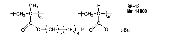
3)剥離フィルム
・基材1:
片面はマット処理、もう片面は表面処理されていないポリエチレンテレフタレートフィルム(膜厚38μm)を作製し、基材1として用いた。
・基材1:
片面はマット処理、もう片面は表面処理されていないポリエチレンテレフタレートフィルム(膜厚38μm)を作製し、基材1として用いた。
・基材2:
市販のポリエチレンテレフタレートフィルム、ルミラー(R)S105(膜厚38μm、東レ製)を基材2として用いた。
市販のポリエチレンテレフタレートフィルム、ルミラー(R)S105(膜厚38μm、東レ製)を基材2として用いた。
・基材3:
市販のポリエチレンテレフタレートフィルム、ルミラー(R)S10(膜厚25μm、東レ製)を基材3として用いた。
市販のポリエチレンテレフタレートフィルム、ルミラー(R)S10(膜厚25μm、東レ製)を基材3として用いた。
<透明層1>
(樹脂溶液の調製)
20質量部の樹脂1を吸湿率が0.2質量%以下の酢酸エチル溶媒と共にミキシングタンクで攪拌して溶解させ、固形分濃度9質量%の樹脂溶液を得た。
なお、以下の透明層2~9において用いる溶媒は、いずれも吸湿率が0.2質量%以下である。
(樹脂溶液の調製)
20質量部の樹脂1を吸湿率が0.2質量%以下の酢酸エチル溶媒と共にミキシングタンクで攪拌して溶解させ、固形分濃度9質量%の樹脂溶液を得た。
なお、以下の透明層2~9において用いる溶媒は、いずれも吸湿率が0.2質量%以下である。
続いて、得られた溶液を絶対濾過精度10μmの濾紙(#63、東洋濾紙(株)製)で濾過し、更に絶対濾過精度2.5μmの金属焼結フィルター(FH025、ポール社製)にて濾過して樹脂溶液1を得た。
(透明層の作製)
上記樹脂溶液1を、基材1の表面処理されていない面に、乾燥後の膜厚が表1記載の膜厚となるようにダイコーターを用いて連続塗布し、100℃で乾燥してポリエチレンテレフタレート上に透明層1を形成させた。
上記樹脂溶液1を、基材1の表面処理されていない面に、乾燥後の膜厚が表1記載の膜厚となるようにダイコーターを用いて連続塗布し、100℃で乾燥してポリエチレンテレフタレート上に透明層1を形成させた。
<透明層2>
20質量部の樹脂1の代わりに下記素材群を使用した以外は透明層1と同様に実施した。
樹脂1 17質量部
樹脂2 3質量部
20質量部の樹脂1の代わりに下記素材群を使用した以外は透明層1と同様に実施した。
樹脂1 17質量部
樹脂2 3質量部
<透明層3>
樹脂1を樹脂3に、酢酸エチル溶媒をトルエン溶媒に変更した以外は透明層1と同様に実施した。
樹脂1を樹脂3に、酢酸エチル溶媒をトルエン溶媒に変更した以外は透明層1と同様に実施した。
<透明層4>
上記方法で作製した透明層3の、基材1に接していない面上に、2μm厚の透明層1を、上記方法にて形成させ、積層体を得た。透明層3と透明層1の積層体を透明層4とする。
上記方法で作製した透明層3の、基材1に接していない面上に、2μm厚の透明層1を、上記方法にて形成させ、積層体を得た。透明層3と透明層1の積層体を透明層4とする。
<透明層5>
20質量部の樹脂1の代わりに下記素材群を使用し、酢酸エチル溶媒をジクロロメタン溶媒に、固形分濃度9質量%を5質量%に変更した以外は透明層1と同様に実施した。
樹脂4 20質量部
添加剤1 3質量部
20質量部の樹脂1の代わりに下記素材群を使用し、酢酸エチル溶媒をジクロロメタン溶媒に、固形分濃度9質量%を5質量%に変更した以外は透明層1と同様に実施した。
樹脂4 20質量部
添加剤1 3質量部
<透明層6>
20質量部の樹脂1の代わりに下記素材群を使用し、乾燥後の膜厚が表1記載の膜厚となるようにし、乾燥温度を110℃にした以外は透明層1と同様に実施した。
樹脂1 20質量部
界面活性剤1 0.02質量部
20質量部の樹脂1の代わりに下記素材群を使用し、乾燥後の膜厚が表1記載の膜厚となるようにし、乾燥温度を110℃にした以外は透明層1と同様に実施した。
樹脂1 20質量部
界面活性剤1 0.02質量部
<透明層7>
20質量部の樹脂1の代わりに下記素材群を使用し、乾燥後の膜厚が表1記載の膜厚となるようにした以外は透明層1と同様に実施した。
樹脂1 18質量部
添加剤2 2質量部
20質量部の樹脂1の代わりに下記素材群を使用し、乾燥後の膜厚が表1記載の膜厚となるようにした以外は透明層1と同様に実施した。
樹脂1 18質量部
添加剤2 2質量部
<透明層8>
基材1を基材2に変更し、乾燥後の膜厚が表1記載の膜厚となるようにした以外は透明層1と同様に実施した。
基材1を基材2に変更し、乾燥後の膜厚が表1記載の膜厚となるようにした以外は透明層1と同様に実施した。
<透明層9>
基材1を基材3に変更し、乾燥後の膜厚が表1記載の膜厚となるようにした以外は透明層1と同様に実施した。
<透明層10>
20質量部の樹脂1の代わりに下記素材群を使用し、樹脂溶液を、基材1の表面処理されていない面に、乾燥後の膜厚が表1記載の膜厚となるようにダイコーターを用いて連続塗布し、60℃で乾燥してポリエチレンテレフタレート上に塗膜を形成させた後、更に窒素パージ下酸素濃度約0.01体積%で160W/cmの空冷メタルハライドランプ(アイグラフィックス(株)製)を用いて、照度200mW/cm2、照射量100mJ/cm2の紫外線を照射して塗膜を硬化させ透明層10を形成させた。
セロキサイド2021P[ダイセル(株)製] 48質量部
CPI 100P[サンアプロ(株)製] 2質量部
基材1を基材3に変更し、乾燥後の膜厚が表1記載の膜厚となるようにした以外は透明層1と同様に実施した。
<透明層10>
20質量部の樹脂1の代わりに下記素材群を使用し、樹脂溶液を、基材1の表面処理されていない面に、乾燥後の膜厚が表1記載の膜厚となるようにダイコーターを用いて連続塗布し、60℃で乾燥してポリエチレンテレフタレート上に塗膜を形成させた後、更に窒素パージ下酸素濃度約0.01体積%で160W/cmの空冷メタルハライドランプ(アイグラフィックス(株)製)を用いて、照度200mW/cm2、照射量100mJ/cm2の紫外線を照射して塗膜を硬化させ透明層10を形成させた。
セロキサイド2021P[ダイセル(株)製] 48質量部
CPI 100P[サンアプロ(株)製] 2質量部
<フィルム1>
市販の片面に易接着層が形成されたポリエチレンテレフタレートフィルム(膜厚80μm、富士フイルム(株)製)をそのまま使用した。
市販の片面に易接着層が形成されたポリエチレンテレフタレートフィルム(膜厚80μm、富士フイルム(株)製)をそのまま使用した。
(透明層の評価)
上記で作製した透明層を前述の方法で評価し、結果を表1に示した。
上記で作製した透明層を前述の方法で評価し、結果を表1に示した。
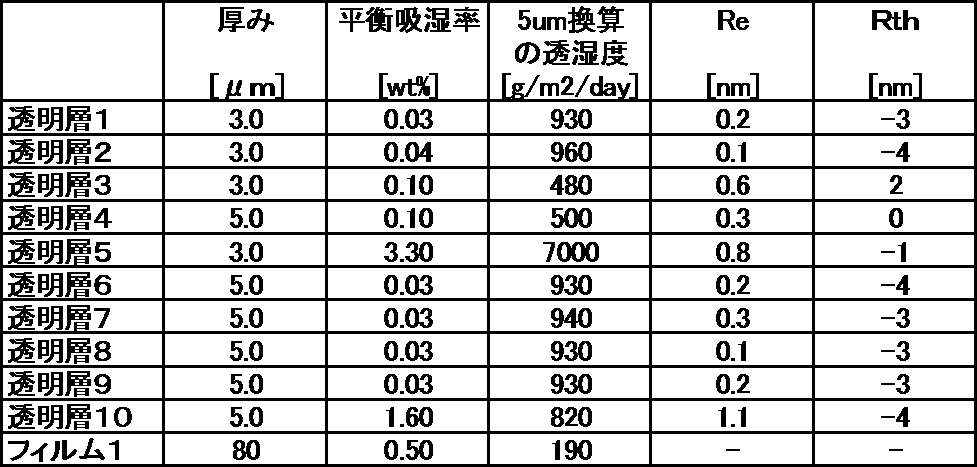
《2》 積層体の作製と評価
(積層体の作製)
1)透明層1~5及びフィルム1の表面処理
透明層1~5について、ポリエチレンテレフタレート基材とは反対側の面にコロナ処理を行い、表面処理した透明層1~5を作製した。また、フィルム1について、易接着層の面にコロナ処理を行い、表面処理したフィルム1を作製した。
なお、透明層6~10はコロナ処理せずに、そのまま使用した。
また、セルロースアセテートフィルム(富士フイルム製、フジタックTG40)を37℃に調温した1.5mol/Lの水酸化ナトリウム水溶液(けん化液)に1分間浸漬した後、フィルムを水洗し、その後、0.05mol/Lの硫酸水溶液に30秒浸漬した後、更に水洗浴を通した。そして、エアナイフによる水切りを3回繰り返し、水を落とした後に70℃の乾燥ゾーンに15秒間滞留させて乾燥し、鹸化処理したセルロースアセテートフィルムを作製した。
(積層体の作製)
1)透明層1~5及びフィルム1の表面処理
透明層1~5について、ポリエチレンテレフタレート基材とは反対側の面にコロナ処理を行い、表面処理した透明層1~5を作製した。また、フィルム1について、易接着層の面にコロナ処理を行い、表面処理したフィルム1を作製した。
なお、透明層6~10はコロナ処理せずに、そのまま使用した。
また、セルロースアセテートフィルム(富士フイルム製、フジタックTG40)を37℃に調温した1.5mol/Lの水酸化ナトリウム水溶液(けん化液)に1分間浸漬した後、フィルムを水洗し、その後、0.05mol/Lの硫酸水溶液に30秒浸漬した後、更に水洗浴を通した。そして、エアナイフによる水切りを3回繰り返し、水を落とした後に70℃の乾燥ゾーンに15秒間滞留させて乾燥し、鹸化処理したセルロースアセテートフィルムを作製した。
2)偏光層の作製
特開2001-141926号公報の実施例1に従い、2対のニップロール間に周速差を与え、長手方向に延伸し、厚み12μmの偏光層を作製した。
特開2001-141926号公報の実施例1に従い、2対のニップロール間に周速差を与え、長手方向に延伸し、厚み12μmの偏光層を作製した。
3)貼り合わせ
表面処理した透明層1~5、表面処理したフィルム1、透明層6~10から選ばれる1つを偏光層の一方の面に有し、上記鹸化処理したセルロースアセテートフィルムを偏光層の他方の面に有する積層体を作製した。より詳細には、表2に示した表面処理した透明層1~5、表面処理したフィルム1、透明層6~10から選ばれる1つと、上記鹸化処理したセルロースアセテートフィルムと(以下、これらを「保護フィルム」とも呼ぶ。)で前述の偏光層を挟んだ後、表2に記載の下記接着剤を用いて、偏光層の吸収軸と保護フィルムの長手方向とが平行になるようにロールツーロールで積層した。
ここで、偏光層に保護フィルムを貼り合せる際には、表面処理した透明層1~5、表面処理したフィルム1については、コロナ処理面が偏光層側となるようにし、透明層6~10についてはポリエチレンテレフタレート基材とは反対側の面が偏光層側となるようにした。
表面処理した透明層1~5、表面処理したフィルム1、透明層6~10から選ばれる1つを偏光層の一方の面に有し、上記鹸化処理したセルロースアセテートフィルムを偏光層の他方の面に有する積層体を作製した。より詳細には、表2に示した表面処理した透明層1~5、表面処理したフィルム1、透明層6~10から選ばれる1つと、上記鹸化処理したセルロースアセテートフィルムと(以下、これらを「保護フィルム」とも呼ぶ。)で前述の偏光層を挟んだ後、表2に記載の下記接着剤を用いて、偏光層の吸収軸と保護フィルムの長手方向とが平行になるようにロールツーロールで積層した。
ここで、偏光層に保護フィルムを貼り合せる際には、表面処理した透明層1~5、表面処理したフィルム1については、コロナ処理面が偏光層側となるようにし、透明層6~10についてはポリエチレンテレフタレート基材とは反対側の面が偏光層側となるようにした。
・接着剤1:
ポリビニルアルコール(クラレ製、PVA-117H)3%水溶液を接着剤として用いた。
・接着剤2:
特開2009-294502号公報の実施例1に記載の接着剤Aに準じて接着剤を調製した。
ポリビニルアルコール(クラレ製、PVA-117H)3%水溶液を接着剤として用いた。
・接着剤2:
特開2009-294502号公報の実施例1に記載の接着剤Aに準じて接着剤を調製した。
続けて、70℃で乾燥した後、透明層1~10の基材であるポリエチレンテレフタレートを、セパレータの剥離装置と同様の装置を用いて連続剥離した。このとき、透明層7は、他の透明層と比べて、剥離に要する力が適度に高く、安定的に剥離フィルムを剥がすことができた。
続けて、帯電防止剤1を2質量%含み、ベースポリマーがブチルアクリレートである粘着剤を透明層上又はフィルム1上に塗工して積層体1~11を作製した。
続けて、帯電防止剤1を2質量%含み、ベースポリマーがブチルアクリレートである粘着剤を透明層上又はフィルム1上に塗工して積層体1~11を作製した。
一方の保護フィルムとして透明層6を用い他方の保護フィルムとしてセルロースアセテートフィルムを用いた積層体7のセルロースアセテートフィルムを透明層6に変更した以外は、積層体7と同様に実施し、偏光層の両面に透明層6が形成された積層体12を作製した。この積層体の初期偏光度は99.9%以上であることを確認した。
(積層体の評価)
上記積層体を40mm×40mmのトムソン刃で打抜き、厚み1mmの50mm×50mmサイズの無アルカリガラス板に粘着剤面を介して貼合した。
1)初期偏光度
上記ガラス板に貼合した積層体の偏光度を前述した方法で算出したところ、全ての積層体の偏光度が99.9%以上であった。偏光度の測定には、日本分光(株)製自動偏光フィルム測定装置VAP-7070を用いた。
上記ガラス板に貼合した積層体の偏光度を前述した方法で算出したところ、全ての積層体の偏光度が99.9%以上であった。偏光度の測定には、日本分光(株)製自動偏光フィルム測定装置VAP-7070を用いた。
2)経時偏光度
上記初期偏光度を測定した試験片を85℃・相対湿度85%の環境で3日間保持した後に、25℃・相対湿度60%の環境で24時間保持し、上記方法にて偏光度を測定した。この偏光度を経時偏光度とした。
上記初期偏光度を測定した試験片を85℃・相対湿度85%の環境で3日間保持した後に、25℃・相対湿度60%の環境で24時間保持し、上記方法にて偏光度を測定した。この偏光度を経時偏光度とした。
3)帯電防止剤の移行率
上記初期偏光度を測定したサンプルを85℃・相対湿度85%の環境で3日間保持した後に25℃・相対湿度60%の環境で24時間さらに保持し、前述の方法で帯電防止剤の移行率を測定し、表2に記載した。
上記初期偏光度を測定したサンプルを85℃・相対湿度85%の環境で3日間保持した後に25℃・相対湿度60%の環境で24時間さらに保持し、前述の方法で帯電防止剤の移行率を測定し、表2に記載した。
4)偏光層接着性
JIS-K-5600-5-6-1に記載のクロスカット法にて評価を行った。作製した積層体の透明層表面に1mm間隔で100個の碁盤目を入れ、セロハンテープ(登録商標)(ニチバン(株)製)で密着試験を行った。新しいセロハンテープを貼った後に剥離し、以下の基準で判定した。
A : 碁盤目中のマスの剥離が起こらない
B : 碁盤目中のマスの剥離が無いものが50%以上100%未満
C : 碁盤目中のマスの剥離が無いものが50%未満
実用上問題が無いのはA、Bの基準である。Aの基準であることが好ましい。
JIS-K-5600-5-6-1に記載のクロスカット法にて評価を行った。作製した積層体の透明層表面に1mm間隔で100個の碁盤目を入れ、セロハンテープ(登録商標)(ニチバン(株)製)で密着試験を行った。新しいセロハンテープを貼った後に剥離し、以下の基準で判定した。
A : 碁盤目中のマスの剥離が起こらない
B : 碁盤目中のマスの剥離が無いものが50%以上100%未満
C : 碁盤目中のマスの剥離が無いものが50%未満
実用上問題が無いのはA、Bの基準である。Aの基準であることが好ましい。
5)液晶表示装置への実装評価(IPS型液晶表示装置への実装)
IPSモードの液晶テレビ(スリム型55型液晶テレビ、バックライトとセルのクリアランスが0.5mm)のリア側偏光板の代わりに、上記作製した積層体を、上記作製した透明層側が液晶セル側に配置されるように、粘着剤を介して液晶セルに貼合した。得られた液晶テレビを、50℃・相対湿度80%の環境で3日間保持した後に、25℃・相対湿度60%の環境に移し、黒表示状態で点灯させ続け、48時間後に目視観察して、光ムラを評価した。
(耐久試験後の正面方向の光ムラレベル)
装置正面から観察した場合の黒表示時の光ムラ(言い換えると、輝度ムラ)を観察し、以下の基準で評価した。
AA: 照度20lxの環境下でムラがほとんど視認されない
A : 照度100lxの環境下でムラがほとんど視認されない
B : 照度100lxの環境下で淡いムラが視認される
C : 照度100lxの環境下で明確なムラが視認される
D : 照度300lxの環境下で明確なムラが視認される
実用上問題が無いのはAA、A、Bの基準であるが、AA及びAの基準であることが好ましい。なお、積層体6を用いた比較例2の液晶表示装置は、全面に酷い光ムラが生じており、前述の評価はできなかった。また、積層体の周辺部分に剥がれが目視観察された。
IPSモードの液晶テレビ(スリム型55型液晶テレビ、バックライトとセルのクリアランスが0.5mm)のリア側偏光板の代わりに、上記作製した積層体を、上記作製した透明層側が液晶セル側に配置されるように、粘着剤を介して液晶セルに貼合した。得られた液晶テレビを、50℃・相対湿度80%の環境で3日間保持した後に、25℃・相対湿度60%の環境に移し、黒表示状態で点灯させ続け、48時間後に目視観察して、光ムラを評価した。
(耐久試験後の正面方向の光ムラレベル)
装置正面から観察した場合の黒表示時の光ムラ(言い換えると、輝度ムラ)を観察し、以下の基準で評価した。
AA: 照度20lxの環境下でムラがほとんど視認されない
A : 照度100lxの環境下でムラがほとんど視認されない
B : 照度100lxの環境下で淡いムラが視認される
C : 照度100lxの環境下で明確なムラが視認される
D : 照度300lxの環境下で明確なムラが視認される
実用上問題が無いのはAA、A、Bの基準であるが、AA及びAの基準であることが好ましい。なお、積層体6を用いた比較例2の液晶表示装置は、全面に酷い光ムラが生じており、前述の評価はできなかった。また、積層体の周辺部分に剥がれが目視観察された。
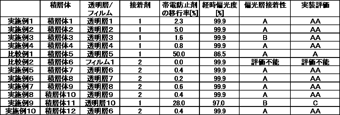
上記表2より、本発明の積層体は、湿熱環境で保持された場合の信頼性に優れ、液晶表示装置に実装した場合に環境変化に伴う液晶表示装置の光ムラを抑制できることがわかった。
本発明によれば、信頼性に優れ、液晶表示装置に実装した場合に環境変化に伴う液晶表示装置の光ムラを抑制できる積層体を歩留りよく提供可能となった。また、この積層体を用いた、光ムラが発生しにくく、信頼性に優れた液晶表示装置を歩留りよく提供可能となった。
本発明を詳細にまた特定の実施態様を参照して説明したが、本発明の精神と範囲を逸脱することなく様々な変更や修正を加えることができることは当業者にとって明らかである。
本出願は、2016年2月5日出願の日本特許出願(特願2016-020717)、2016年5月31日出願の日本特許出願(特願2016-108701)、及び2016年12月26日出願の日本特許出願(特願2016-250983)に基づくものであり、その内容はここに参照として取り込まれる。
本出願は、2016年2月5日出願の日本特許出願(特願2016-020717)、2016年5月31日出願の日本特許出願(特願2016-108701)、及び2016年12月26日出願の日本特許出願(特願2016-250983)に基づくものであり、その内容はここに参照として取り込まれる。
Claims (17)
- 少なくとも、偏光層、接着剤層、透明層および帯電防止剤を含有する層をこの順に配置した積層体であって、
前記透明層の膜厚が0.1~10μmであって、
前記帯電防止剤の湿熱サーモ後の移行率が0~30%である積層体。 - 前記帯電防止剤の湿熱サーモ後の移行率が0.01~30%である請求項1に記載の積層体。
- 前記透明層の平衡吸湿率が2.0質量%以下である請求項1又は2に記載の積層体。
- 前記透明層の5μm換算した透湿度が200~5000g/m2/dayである請求項1~3のいずれか一項に記載の積層体。
- 前記透明層がフッ素系化合物、および/またはケイ素系化合物を含む請求項1~4のいずれか一項に記載の積層体。
- 前記透明層がスチレン系樹脂を含む請求項1~5のいずれか一項に記載の積層体。
- 前記透明層の波長590nmにおける面内レタデーションReが0~20nmであり、且つ波長590nmにおける厚み方向レタデーションRthが-25~25nmである請求項1~6のいずれか一項に記載の積層体。
- 前記透明層が2層以上の層からなる透明層である請求項1~7のいずれか一項に記載の積層体。
- 前記帯電防止剤が有機カチオン化合物を含有する請求項1~8のいずれか一項に記載の積層体。
- 前記帯電防止剤の含有量が、前記帯電防止剤を含有する層の組成物に対し0.01~10質量%である請求項1~9のいずれか一項に記載の積層体。
- 前記偏光層がヨウ素-ポリビニルアルコール錯体を含む請求項1~10のいずれか一項に記載の積層体。
- 液晶セルと、請求項1~11のいずれか一項に記載の積層体を含む液晶表示装置。
- 前記透明層が、前記偏光層と前記液晶セルとの間に配置される請求項12に記載の液晶表示装置。
- さらにバックライトを有し、前記積層体がバックライト側に配置された請求項12または13に記載の液晶表示装置。
- さらにバックライトを有し、前記積層体が視認側に配置された請求項12または13に記載の液晶表示装置。
- 前記液晶セルがIPS方式である請求項12~15のいずれか一項に記載の液晶表示装置。
- 少なくとも、偏光層、接着剤層、透明層および帯電防止剤を含有する層をこの順に配置した積層体であって、
前記透明層の膜厚が0.1~10μmであって、
前記透明層の平衡吸湿率が2.0質量%以下であり、且つ、5μm換算した透湿度が200~5000g/m2/dayであって、
前記帯電防止剤が有機カチオン化合物を含有する、積層体。
Priority Applications (4)
| Application Number | Priority Date | Filing Date | Title |
|---|---|---|---|
| KR1020187021339A KR102091095B1 (ko) | 2016-02-05 | 2017-01-19 | 적층체 및 액정 표시 장치 |
| KR1020207006687A KR102197903B1 (ko) | 2016-02-05 | 2017-01-19 | 적층체 및 액정 표시 장치 |
| CN201780009516.4A CN108603969B (zh) | 2016-02-05 | 2017-01-19 | 层叠体以及液晶显示装置 |
| US16/039,725 US20180321532A1 (en) | 2016-02-05 | 2018-07-19 | Laminate and liquid crystal display device |
Applications Claiming Priority (6)
| Application Number | Priority Date | Filing Date | Title |
|---|---|---|---|
| JP2016-020717 | 2016-02-05 | ||
| JP2016020717 | 2016-02-05 | ||
| JP2016-108701 | 2016-05-31 | ||
| JP2016108701 | 2016-05-31 | ||
| JP2016-250983 | 2016-12-26 | ||
| JP2016250983A JP6600618B2 (ja) | 2016-02-05 | 2016-12-26 | 積層体および液晶表示装置 |
Related Child Applications (1)
| Application Number | Title | Priority Date | Filing Date |
|---|---|---|---|
| US16/039,725 Continuation US20180321532A1 (en) | 2016-02-05 | 2018-07-19 | Laminate and liquid crystal display device |
Publications (1)
| Publication Number | Publication Date |
|---|---|
| WO2017135059A1 true WO2017135059A1 (ja) | 2017-08-10 |
Family
ID=59500129
Family Applications (1)
| Application Number | Title | Priority Date | Filing Date |
|---|---|---|---|
| PCT/JP2017/001807 Ceased WO2017135059A1 (ja) | 2016-02-05 | 2017-01-19 | 積層体および液晶表示装置 |
Country Status (1)
| Country | Link |
|---|---|
| WO (1) | WO2017135059A1 (ja) |
Cited By (2)
| Publication number | Priority date | Publication date | Assignee | Title |
|---|---|---|---|---|
| WO2018221324A1 (ja) * | 2017-06-02 | 2018-12-06 | 日東電工株式会社 | 偏光フィルムおよび画像表示装置 |
| CN115246254A (zh) * | 2021-04-26 | 2022-10-28 | 住友化学株式会社 | 光学层叠体及其卷绕体 |
Citations (8)
| Publication number | Priority date | Publication date | Assignee | Title |
|---|---|---|---|---|
| JP2011227450A (ja) * | 2010-03-31 | 2011-11-10 | Sumitomo Chemical Co Ltd | 偏光性積層フィルムの製造方法、および偏光板の製造方法 |
| JP2013041163A (ja) * | 2011-08-17 | 2013-02-28 | Fujifilm Corp | 光学フィルム積層体、偏光板、画像表示装置、及び光学フィルム積層体の製造方法 |
| WO2013146708A1 (ja) * | 2012-03-27 | 2013-10-03 | 電気化学工業株式会社 | 光学用成形体 |
| JP2015078252A (ja) * | 2013-10-15 | 2015-04-23 | 住友化学株式会社 | 粘着剤付き樹脂フィルム及びそれを用いた光学積層体 |
| JP2015161782A (ja) * | 2014-02-27 | 2015-09-07 | 住友化学株式会社 | 偏光板の製造方法及び偏光板 |
| WO2015182351A1 (ja) * | 2014-05-30 | 2015-12-03 | 住友化学株式会社 | 粘着剤付き偏光板及び液晶表示装置 |
| WO2015194523A1 (ja) * | 2014-06-18 | 2015-12-23 | 住友化学株式会社 | 偏光子、粘着剤付き偏光板及び画像表示装置 |
| KR20150143163A (ko) * | 2014-06-13 | 2015-12-23 | 동우 화인켐 주식회사 | 초박형 편광판 및 이를 구비하는 액정표시장치 |
-
2017
- 2017-01-19 WO PCT/JP2017/001807 patent/WO2017135059A1/ja not_active Ceased
Patent Citations (8)
| Publication number | Priority date | Publication date | Assignee | Title |
|---|---|---|---|---|
| JP2011227450A (ja) * | 2010-03-31 | 2011-11-10 | Sumitomo Chemical Co Ltd | 偏光性積層フィルムの製造方法、および偏光板の製造方法 |
| JP2013041163A (ja) * | 2011-08-17 | 2013-02-28 | Fujifilm Corp | 光学フィルム積層体、偏光板、画像表示装置、及び光学フィルム積層体の製造方法 |
| WO2013146708A1 (ja) * | 2012-03-27 | 2013-10-03 | 電気化学工業株式会社 | 光学用成形体 |
| JP2015078252A (ja) * | 2013-10-15 | 2015-04-23 | 住友化学株式会社 | 粘着剤付き樹脂フィルム及びそれを用いた光学積層体 |
| JP2015161782A (ja) * | 2014-02-27 | 2015-09-07 | 住友化学株式会社 | 偏光板の製造方法及び偏光板 |
| WO2015182351A1 (ja) * | 2014-05-30 | 2015-12-03 | 住友化学株式会社 | 粘着剤付き偏光板及び液晶表示装置 |
| KR20150143163A (ko) * | 2014-06-13 | 2015-12-23 | 동우 화인켐 주식회사 | 초박형 편광판 및 이를 구비하는 액정표시장치 |
| WO2015194523A1 (ja) * | 2014-06-18 | 2015-12-23 | 住友化学株式会社 | 偏光子、粘着剤付き偏光板及び画像表示装置 |
Cited By (2)
| Publication number | Priority date | Publication date | Assignee | Title |
|---|---|---|---|---|
| WO2018221324A1 (ja) * | 2017-06-02 | 2018-12-06 | 日東電工株式会社 | 偏光フィルムおよび画像表示装置 |
| CN115246254A (zh) * | 2021-04-26 | 2022-10-28 | 住友化学株式会社 | 光学层叠体及其卷绕体 |
Similar Documents
| Publication | Publication Date | Title |
|---|---|---|
| JP6600618B2 (ja) | 積層体および液晶表示装置 | |
| CN102272640B (zh) | 光学膜和包括该光学膜的液晶显示器 | |
| TWI752054B (zh) | 經積層分離膜之附黏著劑層的光學膜 | |
| TWI858273B (zh) | 光學積層體及包含該光學積層體之附相位差層之偏光板之圖像顯示裝置 | |
| JP2008249896A (ja) | 偏光板用保護フィルム、偏光板、及び液晶表示装置 | |
| JP2011519434A (ja) | 光学フィルム及びこれを含む情報電子装置 | |
| TWI782896B (zh) | 黏著劑組成物、黏著劑層及附有黏著劑層之光學構件 | |
| JP2014038180A (ja) | 光学フィルム、光学フィルムの製造方法、偏光板及び液晶表示装置 | |
| KR101127914B1 (ko) | 광학 필름 및 이를 포함하는 액정 표시 장치 | |
| JP2025159042A (ja) | 位相差層および粘着剤層付偏光板、ならびに、該位相差層および粘着剤層付偏光板を用いた画像表示装置 | |
| JP6655528B2 (ja) | 偏光板および液晶表示装置 | |
| JP2016501386A (ja) | 偏光板及びこれを含む液晶表示装置 | |
| WO2017135059A1 (ja) | 積層体および液晶表示装置 | |
| CN107589481A (zh) | 带层叠有隔膜的粘合剂层的光学膜 | |
| JP7664036B2 (ja) | 粘着剤組成物、粘着剤層、粘着剤シート、及び光学積層体 | |
| JPWO2014178178A1 (ja) | 偏光板および液晶表示装置 | |
| JP6488242B2 (ja) | 複層フィルムの積層物 | |
| JP2005242171A (ja) | 偏光子保護フィルム及び偏光板 | |
| CN114106741A (zh) | 粘合剂组合物及带粘合剂层的光学膜 | |
| WO2017119245A1 (ja) | 偏光板および液晶表示装置 | |
| JP2024054012A (ja) | 積層体および画像表示装置 | |
| CN114106745A (zh) | 粘合剂组合物及带粘合剂层的光学膜 | |
| KR101497182B1 (ko) | 아크릴계 공중합체, 이를 포함하는 광학 필름 | |
| JP2016006470A (ja) | 偏光板および液晶表示装置 | |
| WO2020250749A1 (ja) | 粘着剤組成物、粘着剤層、粘着剤シート、及び光学積層体 |
Legal Events
| Date | Code | Title | Description |
|---|---|---|---|
| 121 | Ep: the epo has been informed by wipo that ep was designated in this application |
Ref document number: 17747218 Country of ref document: EP Kind code of ref document: A1 |
|
| ENP | Entry into the national phase |
Ref document number: 20187021339 Country of ref document: KR Kind code of ref document: A |
|
| NENP | Non-entry into the national phase |
Ref country code: DE |
|
| 122 | Ep: pct application non-entry in european phase |
Ref document number: 17747218 Country of ref document: EP Kind code of ref document: A1 |