WO2017134941A1 - 中空管材の製造方法 - Google Patents
中空管材の製造方法 Download PDFInfo
- Publication number
- WO2017134941A1 WO2017134941A1 PCT/JP2016/087396 JP2016087396W WO2017134941A1 WO 2017134941 A1 WO2017134941 A1 WO 2017134941A1 JP 2016087396 W JP2016087396 W JP 2016087396W WO 2017134941 A1 WO2017134941 A1 WO 2017134941A1
- Authority
- WO
- WIPO (PCT)
- Prior art keywords
- steel pipe
- hollow tube
- power transmission
- tube material
- portions
- Prior art date
Links
- 239000000463 material Substances 0.000 title claims abstract description 58
- 238000004519 manufacturing process Methods 0.000 title claims abstract description 34
- 229910000831 Steel Inorganic materials 0.000 claims abstract description 90
- 239000010959 steel Substances 0.000 claims abstract description 90
- 238000000034 method Methods 0.000 claims abstract description 23
- 230000005540 biological transmission Effects 0.000 claims description 65
- 239000002184 metal Substances 0.000 claims description 25
- 230000007423 decrease Effects 0.000 claims description 7
- 239000002994 raw material Substances 0.000 abstract description 5
- 230000008719 thickening Effects 0.000 description 26
- 238000005242 forging Methods 0.000 description 20
- 230000004048 modification Effects 0.000 description 15
- 238000012986 modification Methods 0.000 description 15
- 230000008569 process Effects 0.000 description 9
- 239000000047 product Substances 0.000 description 7
- 238000000465 moulding Methods 0.000 description 6
- 230000008859 change Effects 0.000 description 5
- 230000006835 compression Effects 0.000 description 3
- 238000007906 compression Methods 0.000 description 3
- 238000003825 pressing Methods 0.000 description 3
- 239000013585 weight reducing agent Substances 0.000 description 3
- 238000003466 welding Methods 0.000 description 3
- 238000013459 approach Methods 0.000 description 2
- 238000010273 cold forging Methods 0.000 description 2
- 238000005520 cutting process Methods 0.000 description 2
- 230000000694 effects Effects 0.000 description 2
- 238000010438 heat treatment Methods 0.000 description 2
- 230000002093 peripheral effect Effects 0.000 description 2
- 230000004323 axial length Effects 0.000 description 1
- 230000008901 benefit Effects 0.000 description 1
- 238000009826 distribution Methods 0.000 description 1
- 238000005516 engineering process Methods 0.000 description 1
- 239000012467 final product Substances 0.000 description 1
- 238000005304 joining Methods 0.000 description 1
- 230000009467 reduction Effects 0.000 description 1
- 238000007493 shaping process Methods 0.000 description 1
- 239000007787 solid Substances 0.000 description 1
Images


Classifications
-
- B—PERFORMING OPERATIONS; TRANSPORTING
- B21—MECHANICAL METAL-WORKING WITHOUT ESSENTIALLY REMOVING MATERIAL; PUNCHING METAL
- B21J—FORGING; HAMMERING; PRESSING METAL; RIVETING; FORGE FURNACES
- B21J5/00—Methods for forging, hammering, or pressing; Special equipment or accessories therefor
- B21J5/02—Die forging; Trimming by making use of special dies ; Punching during forging
- B21J5/025—Closed die forging
-
- B—PERFORMING OPERATIONS; TRANSPORTING
- B21—MECHANICAL METAL-WORKING WITHOUT ESSENTIALLY REMOVING MATERIAL; PUNCHING METAL
- B21J—FORGING; HAMMERING; PRESSING METAL; RIVETING; FORGE FURNACES
- B21J5/00—Methods for forging, hammering, or pressing; Special equipment or accessories therefor
- B21J5/06—Methods for forging, hammering, or pressing; Special equipment or accessories therefor for performing particular operations
- B21J5/08—Upsetting
-
- B—PERFORMING OPERATIONS; TRANSPORTING
- B21—MECHANICAL METAL-WORKING WITHOUT ESSENTIALLY REMOVING MATERIAL; PUNCHING METAL
- B21K—MAKING FORGED OR PRESSED METAL PRODUCTS, e.g. HORSE-SHOES, RIVETS, BOLTS OR WHEELS
- B21K1/00—Making machine elements
- B21K1/06—Making machine elements axles or shafts
- B21K1/063—Making machine elements axles or shafts hollow
-
- B—PERFORMING OPERATIONS; TRANSPORTING
- B21—MECHANICAL METAL-WORKING WITHOUT ESSENTIALLY REMOVING MATERIAL; PUNCHING METAL
- B21K—MAKING FORGED OR PRESSED METAL PRODUCTS, e.g. HORSE-SHOES, RIVETS, BOLTS OR WHEELS
- B21K1/00—Making machine elements
- B21K1/06—Making machine elements axles or shafts
- B21K1/10—Making machine elements axles or shafts of cylindrical form
-
- F—MECHANICAL ENGINEERING; LIGHTING; HEATING; WEAPONS; BLASTING
- F16—ENGINEERING ELEMENTS AND UNITS; GENERAL MEASURES FOR PRODUCING AND MAINTAINING EFFECTIVE FUNCTIONING OF MACHINES OR INSTALLATIONS; THERMAL INSULATION IN GENERAL
- F16C—SHAFTS; FLEXIBLE SHAFTS; ELEMENTS OR CRANKSHAFT MECHANISMS; ROTARY BODIES OTHER THAN GEARING ELEMENTS; BEARINGS
- F16C2220/00—Shaping
- F16C2220/40—Shaping by deformation without removing material
- F16C2220/42—Shaping by deformation without removing material by working of thin-walled material such as sheet or tube
-
- F—MECHANICAL ENGINEERING; LIGHTING; HEATING; WEAPONS; BLASTING
- F16—ENGINEERING ELEMENTS AND UNITS; GENERAL MEASURES FOR PRODUCING AND MAINTAINING EFFECTIVE FUNCTIONING OF MACHINES OR INSTALLATIONS; THERMAL INSULATION IN GENERAL
- F16C—SHAFTS; FLEXIBLE SHAFTS; ELEMENTS OR CRANKSHAFT MECHANISMS; ROTARY BODIES OTHER THAN GEARING ELEMENTS; BEARINGS
- F16C2220/00—Shaping
- F16C2220/40—Shaping by deformation without removing material
- F16C2220/46—Shaping by deformation without removing material by forging
-
- F—MECHANICAL ENGINEERING; LIGHTING; HEATING; WEAPONS; BLASTING
- F16—ENGINEERING ELEMENTS AND UNITS; GENERAL MEASURES FOR PRODUCING AND MAINTAINING EFFECTIVE FUNCTIONING OF MACHINES OR INSTALLATIONS; THERMAL INSULATION IN GENERAL
- F16C—SHAFTS; FLEXIBLE SHAFTS; ELEMENTS OR CRANKSHAFT MECHANISMS; ROTARY BODIES OTHER THAN GEARING ELEMENTS; BEARINGS
- F16C3/00—Shafts; Axles; Cranks; Eccentrics
- F16C3/02—Shafts; Axles
Definitions
- the present invention relates to a method for producing a hollow tube material.
- This application claims priority based on Japanese Patent Application No. 2016-021153 for which it applied to Japan on February 5, 2016, and uses the content here.
- a drive shaft for transmitting the driving force output from the engine via the transmission to the tire and a propeller shaft for transmitting the output of the engine mounted on the front part of the vehicle body to the rear wheel as the driving wheel,
- a power transmission system shaft for an automobile that is connected to the left and right drive shafts to prevent torque steer, the weight reduction due to the hollowing out of the conventional solid parts has already been put into practical use.
- Such a hollow power transmission system shaft often has an outer diameter and an inner diameter that change at each position along the axial direction, and has been manufactured by the manufacturing methods listed below.
- Patent Document 1 discloses an invention for manufacturing a hollow propeller shaft and a drive shaft by this method.
- the axial center of the product can be thinned, so it is possible to reduce the weight of the power transmission shaft.
- the process of joining between an axial direction center part and an axial direction both ends is required, the raise of manufacturing cost cannot be avoided.
- a drive shaft for example, a drive shaft, a propeller shaft, and a hollow power transmission system shaft (hollow tube material) connected to the left and right drive shafts.
- a hollow power transmission system shaft hollow tube material
- An object of the present invention is to provide a method that can inexpensively manufacture hollow tubes having different cross-sectional shapes along the axial direction.
- the inventors of the present invention can inexpensively produce hollow tubes having different cross-sectional shapes along the axial direction by adopting the following steps (A) and (B).
- the present invention was completed by finding out that it can be done and further studying it.
- a steel pipe as a material is placed inside an outer mold having the same inner shape as the outer shape of the product to be manufactured
- One aspect of the present invention includes a thickened portion, a bulged portion having an outer diameter larger than the thickened portion, and a bulged portion, from both axial end portions toward a central position in the axial direction.
- the steel pipe is compressed in the axial direction by reducing the relative distance between the pair of pressurizing dies in a state in which the cored bar portion having a gap is inserted with the inner surface of the steel pipe being separated at least partially. And a process.
- an outer diameter may become small as the said cored bar part goes to the front-end
- the outer diameter of the cored bar part may change stepwise or continuously depending on the thickness of the thickened part.
- contact portions of the pair of pressure dies with both end surfaces in the axial direction of the steel pipe are inclined toward the outside of the steel pipe. It may be.
- the hollow tube material may be a power transmission shaft for an automobile.
- the power transmission system shaft may be a power transmission system shaft connected to a drive shaft, a propeller shaft, or left and right drive shafts.
- a hollow tube suitable for use as a hollow power transmission system shaft connected to, for example, a drive shaft, a propeller shaft, and left and right drive shafts is provided at low cost. it can.
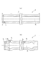
- FIG. 1 is a cross-sectional view illustrating a method for producing a hollow tube material according to an embodiment of the present invention, where (a) shows before forging and (b) shows after forging.
- a hollow power transmission system shaft 1 for an automobile is manufactured in one step by cold forging.
- the power transmission shaft 1 has a thickened portion 3-increase from both end positions 2-1 and 2-2 in the direction along the axis CL (hereinafter referred to as the axial direction) toward the central position 2-3 in the axial direction. 1, 3-2, bulging portions 4-1 and 4-2, and a central portion 5. That is, as shown in FIG. 1B, the power transmission shaft 1 includes a thickening part 3-1, a bulging part 4-1, a central part 5, a bulging part 4-2, and a thickening part 3-2. Are formed successively in this order.
- the thickening portions 3-1 and 3-2 are the thickest portions among the thickening portions 3-1 and 3-2, the bulging portions 4-1 and 4-2, and the central portion 5.
- the thicknesses of the thickening portions 3-1 and 3-2 are substantially constant at each position in the axial direction of the power transmission shaft 1.
- the outer diameters of the thickening portions 3-1 and 3-2 are substantially constant at each position in the axial direction of the power transmission shaft 1, and are substantially the same as the outer diameter of the steel pipe 6 that is a material.
- the inner diameters of the thickening portions 3-1 and 3-2 are substantially constant at each position in the axial direction of the power transmission shaft 1 and are smaller than the inner diameter of the steel pipe 6.
- the bulging portions 4-1 and 4-2 are portions having an outer diameter larger than that of the thickening portions 3-1 and 3-2 and thinner than that of the thickening portions 3-1 and 3-2.
- the outer diameters of the bulging portions 4-1 and 4-2 gradually increase starting from the outer diameter of the thickening portions 3-1 and 3-2.
- the maximum value is obtained at a substantially central position, and then gradually decreases toward the central portion 5.
- the inner diameters of the bulging portions 4-1 and 4-2 gradually increase starting from the inner diameter of the thickening portions 3-1 and 3-2, and the axial directions of the bulging portions 4-1 and 4-2 are increased.
- the maximum value is obtained at a substantially central position, and then gradually decreases toward the central portion 5.
- the central portion 5 has a smaller outer diameter than the bulging portions 4-1 and 4-2 on both sides thereof. Further, the outer diameter of the central portion 5 is substantially constant at each position in the axial direction of the power transmission system shaft 1 and substantially coincides with the outer diameter of the steel pipe 6 that is a material. Further, the inner diameter of the central portion 5 is substantially constant at each position in the axial direction of the power transmission system shaft 1 and substantially coincides with the inner diameter of the steel pipe 6. Therefore, the inner diameter of the central part 5 is larger than the inner diameters of the thickening parts 3-1, 3-2. Accordingly, since the central portion 5 is neither enlarged nor thickened, the thickness of the central portion 5 is substantially the same as the thickness of the steel pipe 6 at each position in the axial direction of the power transmission system shaft 1 and is substantially the same. It is constant.
- the hardness of the central portion 5 is substantially the same as the hardness of the steel pipe 6 that is a material, and there is almost no change before and after forging.
- the thickened portions 3-1 and 3-2 are thickened by forging, and thus are work-hardened and are harder than the steel pipe 6.
- the bulging portions 4-1 and 4-2 are also enlarged by forging, they are work hardened and are harder than the hardness of the steel pipe 6.
- the power transmission shaft 1 is a power transmission shaft for an automobile.
- the characteristics to torsional strength and torsional fatigue required as basic performance are sufficiently improved.
- the axial load increases in proportion to the increase in strength of the material.
- the axial load is about 350 tons even with the S35CB softening material, it is only about 700 tons with a high-strength material of 1000 MPa class, and can be sufficiently manufactured even with a mass production press.
- a steel pipe 6 having a constant thickness which is a material, is an outer metal having an inner surface shape 7a having the same shape as the outer shape of the power transmission system shaft 1.
- a gap is provided between the outer surface of the steel pipe 6 and the inner surface of the outer mold 7, the size of the gap is slight.
- base portions 8-1 and 8-2 which will be described later, have a substantially cylindrical shape with an outer diameter that substantially matches the inner diameter of the end portion of the inner surface shape 7a of the outer mold 7. For this reason, the steel pipe 6 and the base portions 8-1 and 8-2 can be arranged substantially coaxially by simply placing them in the outer mold 7. If it is necessary to coaxially arrange the steel pipes 6 with higher accuracy, the configuration described later with reference to FIG. 9 can also be employed.
- the portion corresponding to the thickening portion 3-1 has a constant distance r1 from the axis CL.
- the distance r2 from the axis CL is the same as the distance r1 of the thickening portion 3-1 at one end thereof, but as it approaches the central portion 5, It gradually increases, and after reaching the maximum value, gradually decreases toward the other end.
- the distance r3 of the portion corresponding to the central portion 5 is the same as the distance r2 at the other end portion, and is constant until reaching the bulging portion 4-2 along the axis CL.
- the distance r4 from the axis line CL is the same as the distance r3 at one end thereof, but gradually as it approaches the thickening portion 3-2. It increases, and after passing through the maximum value, gradually decreases toward the other end.
- the portion corresponding to the thickened portion 3-2 has a constant distance r5 from the axis CL and is the same as the distance r4 at the other end.
- the distance r1 and the distance r5 are equal to each other.
- a gap is provided between the outer surface of the steel pipe 6 and the inner surface shape 7 a of the outer mold 7.
- the size of the gap is not constant when viewed along the direction of the axis CL, and a difference is provided according to the purpose.
- the gap dimension is reduced by two purposes. It has been established. If only these two objectives 1 and 2 are achieved, it is conceivable to simply increase the gap.
- the gap W1 (mm) between the inner surface of the outer mold 7 and the outer surface of the steel pipe 6 in the radial direction of the steel pipe 6 is a steel pipe that is a raw pipe before processing.
- W1 is preferably 0.01 ⁇ d1 or more from the viewpoint of the above object 1.
- W1 is 0.05 ⁇ d1 or less. From the above, it is preferable to adopt the gap W1 (mm) in the portion A from the range defined by the equation of 0.01 ⁇ d1 ⁇ W1 ⁇ 0.05 ⁇ d1.
- the gap in the portion B it is preferable to adopt the gap W1 (mm) from the range defined by the formula of 0.10 ⁇ d1 ⁇ W1 ⁇ 0.25 ⁇ d1.
- the steel pipe 6 may be passed through the outer mold 7, and the gap W1 (mm) is preferably set to approximately 0 (zero) mm.
- the outer mold 7 has a left and right divided structure, similar to a mold used for general die forging, and a product after molding can be taken out by dividing into two. It is configured to be able to. That is, the outer mold 7 is composed of a pair of molds divided into two by the dividing surface having the shape shown in FIG. , 4-2, the power transmission shaft 1 can be taken out from the outer mold 7 by dividing the pair of molds into two.
- both end surfaces 6-1 and 6-2 in the axial direction of the steel pipe 6 are respectively attached to a pair of upper and lower molds (punch with a core metal) 10-1 and 10-2.
- the mold 10-1 has a base portion 8-1 and a core metal portion 9-1.
- the mold 10-2 has a base portion 8-2 and a core metal portion 9-2.
- the base portions 8-1 and 8-2 press the steel pipe 6 from both ends toward the center in the axial direction.
- the base portions 8-1 and 8-2 have a substantially cylindrical shape with an outer diameter substantially matching the inner diameter of the inner surface 7 a of the outer mold 7, and can be inserted into and removed from the end of the outer mold 7. It is.
- the cored bar portions 9-1 and 9-2 are coaxially and integrally provided with respect to the base portions 8-1 and 8-2, and the inner surface shape 1-1 of both end portions in the axial direction of the power transmission shaft 1 is provided.
- , 1-2 have outer surface shapes 9-1a, 9-2a having the same shape (that is, the same shape as the inner surfaces of the thickening portions 3-1, 3-2).
- the clearance W2 (mm) between the outer surface of the cored bar parts 9-1 and 9-2 and the inner surface of the steel pipe 6 before forging is such that the inner diameter of the steel pipe 6 is d2 (mm) and the plate thickness is t (mm). In this case, it can be set appropriately within the range of 0.10 ⁇ (d2-2 ⁇ t) ⁇ W2 ⁇ 0.25 ⁇ (d2-2 ⁇ t).
- the thickened portions 3-1 and 3-2 are formed in the portion A in FIG. 1 (b) by the axial pressing by the dies 10-1 and 10-2. More specifically, as shown in FIG. 1 (a), before the shafts are pushed by the base portions 8-1 and 8-2, the outer surfaces of the core metal portions 9-1 and 9-2 and the inner surface of the steel pipe 6 are interposed. Is provided with a gap. Then, by being compressed by the base portions 8-1 and 8-2, the thickness increases while the inner diameter of the portion to be increased decreases, and finally the outer surface of the core metal portions 9-1 and 9-2 The thickened portions 3-1 and 3-2 have the internal shape of the final product that matches the above.
- FIG. 2 is a cross-sectional view for explaining each dimension of the hollow tube material processed by the method for manufacturing a hollow tube material according to the present embodiment, wherein (a) shows each part size of the steel pipe 6 that is a processed material, (B) shows each part dimension of the power transmission system shaft 1 after a process.
- the total length L is 100 mm to 2000 mm
- the outer diameter d is 20 mm to 100 mm
- the plate thickness t is 2 mm to 20 mm
- t ⁇ d Those satisfying / 2 can be preferably employed.
- the power transmission shaft 1 illustrated in FIG. 2B satisfies both the following condition 1 regarding the wall thickness of each part and the following condition 2 regarding the outer diameter of each part.
- Condition 1 t 1 > t 2 and t 1 > t 3 and each of t 1 , t 2 , and t 3 is 4 mm or more and 15 mm or less.
- Condition 2 D 2 > D 1 and D 2 > D 3 and all of 20 mm ⁇ D 1 ⁇ 100 mm, 22 mm ⁇ D 2 ⁇ 125 mm, and 20 mm ⁇ D 3 ⁇ 100 mm are satisfied.
- the axial length L (mm) of the steel pipe 6 satisfies the following condition 3 as described above.
- Condition 3 100 mm ⁇ L ⁇ 2000 mm
- the molds 10-1 and 10-2 are extracted from the molded power transmission system shaft 1, the outer mold 7 is divided into left and right parts, and the power transmission system shaft 1 is removed.
- the hollow power transmission system shaft 1 is manufactured by one-step die forging.
- the outer mold 7 is first divided into two parts and the power transmission system shaft 1 is taken out.
- the molds 10-1 and 10-2 may be extracted from the power transmission system shaft 1.
- the procedure of extracting the molds 10-1 and 10-2 from the power transmission system shaft 1 before the power transmission system shaft 1 is taken out by dividing the outer mold 7 into two parts More preferred. The reason is that when the molds 10-1 and 10-2 are extracted from the power transmission system shaft 1, the bulging portions 4-1 and 4-2 of the power transmission system shaft 1 are formed with respect to the recess formed in the inner surface shape 7a.
- the outer mold 7 can be grasped and the molds 10-1 and 10-2 can be easily pulled out. That is, the dies 10-1 and 10-2 can be pulled out without directly gripping the power transmission shaft 1 itself, so that there is no possibility of damaging the power transmission shaft 1.
- FIG. 3 is a cross-sectional view showing a modification of the pair of molds 10-1 and 10-2 in the above embodiment, where (a) corresponds to FIG. 1 (a), and (b) shows FIG. It corresponds to b).
- the core metal portion 9- of the dies 10-1 and 10-2 is reduced.
- 1, 9-2 have a tapered shape in which the outer diameter gradually decreases toward the tip.
- the outer diameters of the core metal portions 9-1 and 9-2 are set to be increased.
- 3-2 should be changed stepwise or continuously depending on the wall thickness. More specifically, when the cored bar portions 9-1 and 9-2 are provided with a tapered shape, the thicknesses of the increased thickness portions 3-1 and 3-2 are larger than the bulging portions 4-1 and -4 from the pipe ends. It gradually increases as it goes to 4-2. As a result, the thickness at the portion where the thickening portions 3-1 and 3-2 are switched to the bulging portions 4-1 and 4-2 can be maximized, so that the mechanical strength of such a shape switching portion is increased. Therefore, a more excellent power transmission shaft 1 can be obtained. In addition, when the cored metal parts 9-1 and 9-2 are provided with a tapered shape, there is an advantage that the molds 10-1 and 10-2 can be easily extracted after the die forging.
- FIG. 4 is a cross-sectional view for showing the taper angle ⁇ of the cored bar portion 9-1 used in the above modification.
- FIG. 5 is a cross-sectional view of the steel pipe 6 and the core metal part 9-1 when viewed in a cross section including the axis CL thereof.
- FIG. 5A shows a core metal part 9-1 having a constant taper angle.
- (B) shows the time when the molding is completed when using the cored bar part 9-1 whose taper angle changes stepwise, and (c) shows the taper angle.
- the figure shows the time when the molding is completed when the cored bar part 9-1 is continuously changed.
- the bulging portion 4-1 is not shown for the sake of explanation.
- the taper angle ⁇ of the cored bar portion 9-1 shown in FIG. 4 is preferably 0.3 ° or more and 10.0 ° or less.
- the taper angle ⁇ referred to here is an inclination angle with respect to a straight line parallel to the axis CL.
- the cored bar part 9-1 shown in FIG. 5 (a) has the same shape as the cored bar part 9-1 shown in FIGS. 3 (a) and 3 (b).
- the thickness of the manufactured power transmission shaft 1 can be changed stepwise.
- the taper angle ⁇ shown in FIG. 4 is changed in three stages of A part, B part and C part.
- the taper angles ⁇ of the respective parts A to C may be appropriately combined within a range of 0.3 ° to 10.0 °.
- the thickness of the manufactured power transmission shaft 1 can be continuously changed.
- the taper angle ⁇ may be appropriately changed so as to be within a range of 0.3 ° to 10.0 ° at each position in the axial direction.
- FIG. 6 is a cross-sectional view showing another modification of the pair of molds 10-1 and 10-2 shown in FIG. 1, in which (a) corresponds to FIG. 1 (a), and (b) This corresponds to FIG.
- the base portions 8-1 and 8-2 having the shape shown in FIG. 6 are employed for the reasons described later. That is, the base portions 8-1 and 8-2 in the present modified example have contact portions 8-1a and 8-2a that contact both end surfaces 6-1 and 6-2 in the axial direction of the steel pipe 6, and It inclines so that it may leave
- the contact portions 8-1a and 8-2a have such an inclined shape, it is possible to easily align the axes when the molds 10-1 and 10-2 are set on the steel pipe 6. That is, since the abutting portions 8-1a and 8-2a have substantially conical surfaces, the tapered tip portion can be inserted into the tube end of the steel pipe 6 and the axial alignment between the both is easy. .
- contact portions 8-1a and 8-2a are formed in an inclined manner as described above, they are not formed in an inclined manner (see FIG. 1 (a) and FIG. 1 (b)). Thus, the force in the tube expansion direction is more effectively applied to the portions formed as the bulging portions 4-1, 4-2.
- the contact portion 8-1a (8-2a) can be first applied to the inner peripheral edge of the end portion of the steel pipe 6.
- the bulging portion 4-1 (4) extends from the inner peripheral edge of the end portion of the steel pipe 6 toward the bulging portion 4-1 (4-2).
- -2) can be pushed radially outward and fed into the recess of the inner surface shape 7a.
- the inclination serves to properly guide the material flow at the end of the steel pipe 6 and avoid buckling (the collapse of the bulging portions 4-1, 4-2 inward in the radial direction). Therefore, even if the desired product shape has large bulging portions 4-1, 4-2, it can be molded without buckling.
- FIG. 8 is a cross-sectional view showing still another modification of the pair of molds 10-1 and 10-2 shown in FIG. 1, in which (a) corresponds to (a) of FIG. ) Corresponds to (b) of FIG.
- the cored bar portions 9-1 and 9-2 have the above-described tapered shape, and the contact portions 8-1a and 8-2a are formed to be inclined.
- the molds 10-1 and 10-2 having the shape of both are adopted. According to this modified example, the above-described effect due to the tapered metal core portions 9-1 and 9-2 and the above-described effect due to the inclined contact portions 8-1a and 8-2a are obtained. Both can be demonstrated.
- a flat circular shape is adopted as the tip shape of the cored bar portions 9-1 and 9-2.
- the shape is not limited to this, and in addition to a hemispherical shape or a tapered tapered shape (Chamfering) (C You may employ
- the present invention is not limited to the above-described various embodiments, and configurations appropriately modified can be employed.
- the steel pipe 6 whose material is steel has been described.
- the present invention is not limited to steel but may be applied to hollow tubes made of other plastically deformable materials. .
- the axis of the inner surface (inner surface shape 7a) of the outer mold 7 and the axis of the steel pipe 6 need to be accurately coaxially arranged.
- a mold 10-1 (10-2) shown in FIG. 9 may be employed. That is, as shown in FIG. 9, a highly accurate coaxial arrangement can be achieved by thickening the base portion of the cored bar portion 9-1 (9-2) (portion connected to the base portions 8-1 and 8-2). It becomes possible. More specifically, the base portion has a tapered surface having an outer diameter slightly larger than or substantially equal to the inner diameter of the steel pipe 6 and tapering toward the tips of the core metal portions 9-1 and 9-2. 8x is formed. And the steel pipe 6 can be hold
- the present invention is applied to cold forging.
- the present invention is not limited to this, and the steel pipe 6 is preheated to, for example, 600 ° C. and then placed in the outer mold 7.
- a form in which compression processing is performed by 1,10-2 can also be adopted.
- energization heating can be employed as a method for heating the steel pipe 6 in advance.
- the outline of the manufacturing method of the hollow tube material according to various embodiments described above is summarized below.
- (1) The manufacturing method of this hollow tube material is larger than the thickening portions 3-1, 3-2 and the thickening portions 3-1, 3-2 from the both end portions in the axial direction toward the central position in the axial direction.
- Manufactures a hollow tube (power transmission shaft 1) having bulging portions 4-1 and 4-2 having a large outer diameter and a central portion 5 having a smaller outer diameter than the bulging portions 4-1 and 4-2.
- a steel pipe 6 as a raw material is disposed in an outer mold 7 having an inner surface having the same shape as the outer shape of the hollow tube material (power transmission system shaft 1), at least partially separated from the inner surface.
- both the pair of base portions 8-1 and 8-2 may be brought close to each other, or one of the pair of base portions 8-1 and 8-2 is fixed. In addition, the other may be brought close to the one.
- the outer diameters of the cored bar portions 9-1 and 9-2 may become smaller toward the tip.
- the outer diameters of the core metal parts 9-1 and 9-2 change stepwise or continuously depending on the thickness of the thickening parts 3-1 and 3-2 It may be.
- the base portions 8-1 and 8-2 of the core metal portions 9-1 and 9-2 are in contact with both end surfaces in the axial direction of the steel pipe 6.
- the contact portion may be formed to be inclined toward the outside of the steel pipe 6.
- the hollow tube material may be a power transmission shaft 1 for an automobile.
- the power transmission system shaft 1 may be a power transmission system shaft connected to a drive shaft, a propeller shaft, or left and right drive shafts.
- a drive shaft, a propeller shaft, and a hollow power transmission system shaft connected to the left and right drive shafts can be manufactured at low cost by one-step die forging. Can do.
Landscapes
- Engineering & Computer Science (AREA)
- Mechanical Engineering (AREA)
- General Engineering & Computer Science (AREA)
- Ocean & Marine Engineering (AREA)
- Forging (AREA)
- Shafts, Cranks, Connecting Bars, And Related Bearings (AREA)
- Shaping Metal By Deep-Drawing, Or The Like (AREA)
- Heat Treatment Of Articles (AREA)
Abstract
Description
本願は、2016年2月5日に、日本国に出願された特願2016-021153号に基づき優先権を主張し、その内容をここに援用する。
この方法では、軸方向に沿って外径および内径が変化する形状を有する動力伝達系シャフトを製造する際、軸方向中央部と軸方向両端部とを別々に製造し、これらを摩擦圧接により接合する。この方法では、軸方向中央部は鋼管を切断することにより製造し、軸方向両端部は鍛造品を削り出して製造する。
この方法では、軸方向に沿って肉厚が一定である鋼管を用意し、そしてその両端部をロータリースウェージングにより薄肉化や縮径、増肉することにより製造する。下記特許文献1には、この方法により、中空のプロペラシャフトやドライブシャフトを製造する発明が開示されている。
(A)素材である鋼管を、製造しようとする製品の外形と同じ形状の内面形状を有する外金型の内部に配置し、
(B)この鋼管の軸方向の両端部それぞれを鋼管の軸方向中央位置へ向かって押圧可能なベース部と、このベース部に設けられて製品の軸方向両端部の内面形状と同じ形状の外面形状を有する芯金部とを有する、一対の金型の間で、鋼管を軸方向に圧縮する。
(1)本発明の一態様は、軸方向の両端部から軸方向の中央位置へ向けて、増肉部と、前記増肉部よりも外径が大きい膨出部と、前記膨出部よりも外径が小さい中央部と、を有する中空管材を製造する方法であって、素材である鋼管を、前記中空管材の外形と同じ形状の内面を有する外金型の内部に、前記内面から少なくとも一部を離間させて配置する工程と;前記鋼管の軸方向の両端面にそれぞれ当接する一対の加圧金型間に、前記中空管材の軸方向の両端部の内面形状と同じ形状の外面形状を有する芯金部を前記鋼管の内面に対して少なくとも一部を離間させて挿通させた状態で、前記一対の加圧金型間の相対的な距離を縮めて前記鋼管を軸方向に圧縮する工程と;を有する。
(2)上記(1)において、前記芯金部が、その先端に向かうにつれて外径が小さくなってもよい。
(3)上記(2)の場合、前記芯金部の外径が、前記増肉部の肉厚に応じて段階的または連続的に変化してもよい。
(4)上記(1)~(3)のいずれか一項において、前記一対の加圧金型における前記鋼管の軸方向の両端面との当接部が、前記鋼管の外側へ向けて傾斜していてもよい。
(5)上記(1)~(4)のいずれか一項において、前記中空管材が、自動車用の動力伝達系シャフトであってもよい。
(6)上記(5)の場合、前記動力伝達系シャフトが、ドライブシャフト、プロペラシャフトまたは左右のドライブシャフトに接続される動力伝達系シャフトであってもよい。
図1は、本発明の一実施形態に係る中空管材の製造方法を示す断面図であって、(a)が鍛造加工前を示し、(b)が鍛造加工後を示す。
動力伝達系シャフト1が左右のドライブシャフトに接続される中空の動力伝達系シャフトである場合には、この増肉部3-1,3-2の外面にスプラインが刻設される。
また、中央部5の内径は、動力伝達系シャフト1の軸方向の各位置で略一定でかつ、鋼管6の内径と略一致する。よって、中央部5の内径は、増肉部3-1,3-2の内径よりも大きい。
したがって、中央部5は拡径も増肉もされていないため、中央部5の肉厚は、動力伝達系シャフト1の軸方向の各位置で、鋼管6の肉厚とほぼ同じでかつ、略一定である。
一方、増肉部3-1,3-2は鍛造加工により増肉されているため、加工硬化しており、鋼管6の時の硬度よりも硬くなっている。また、膨出部4-1,4-2も、鍛造加工により拡径されているため、加工硬化しており、鋼管6の時の硬度よりも硬くなっている。
はじめに、図1(a)に示すように、素材である、肉厚一定の鋼管6を、動力伝達系シャフト1の外形と同じ形状の内面形状7aを有する外金型7の内部に、外金型7の内面から僅かに離間させて配置する。すなわち、内面(内面形状7a)の軸線と鋼管6の軸線とが同軸(軸線CL)となるように配置する。鋼管6の外面と外金型7の内面との間には隙間が設けられているものの、この隙間の寸法は僅かである。なおかつ、後述のベース部8-1,8-2は、外金型7の内面形状7aの端部内径と略一致する外径の略円柱形状を有している。そのため、鋼管6及びベース部8-1,8-2を普通に外金型7内に入れるだけで、略同軸配置とすることができる。もし、さらに高い精度で鋼管6を同軸配置する必要が有る場合には、図9を用いて後述する構成も採用可能である。
続く膨出部4-1に対応する部位では、軸線CLからの距離r2が、その一方の端部において増肉部3-1の距離r1と同じであるが、中央部5に向かって近付くにつれて徐々に増していき、そして最大値を経てから他方の端部に向けて徐々に減っていく。
続いて、膨出部4-2に対応する部位では、軸線CLからの距離r4が、その一方の端部において距離r3と同じであるが、増肉部3-2に向かって近付くにつれて徐々に増していき、そして最大値を経てから他方の端部に向けて徐々に減っていく。
続いて、増肉部3-2に対応する部位は、軸線CLからの距離がr5で一定でかつ、前記他方の端部における距離r4と同じである。
なお、距離r1と距離r5は互いに等しい。
具体的に言うと、図1(b)のA部(増肉部3-1,3-2)では、鋼管6を外金型7内に入れる際にスムーズに通すため(目的1)と、外金型7内で型鍛造により変形する鋼管6が外金型7との間に生じる摩擦を抑えて材料の流れをスムーズにするため(目的2)と、の二つの目的により、隙間寸法が定められている。なお、これら二つの目的1,2を達成するだけであれば、単純に隙間を大きくすることも考えられるが、それでは鋼管6が径方向外側に向かって過度に太ろうとする変形をその周囲より拘束できないため、鋼管6の座屈変形を招く虞がある。そのため、隙間を積極的に設けてはいるものの、その寸法が過度なもとならないように定められている。
また、図1(b)のB部(膨出部4-1,4-2)では、鋼管6の外径を太らせるために、大きめの隙間寸法を採用している。
そして、図1(b)のC部(中央部5)では、拡径も増肉も行わないので、鋼管6を外金型7内に入れる際にスムーズに通す目的だけのために、最小限の隙間寸法を採用している。このC部においては、極力、隙間を空けないことが好ましい。
まず、A部における隙間の下限値について言うと、鋼管6の径方向における、外金型7の内面と鋼管6の外面との間の隙間W1(mm)は、加工前の素管である鋼管6の軸方向の任意位置における外径をd1(mm)とした場合に、W1は0.01×d1以上とすることが、上記目的1の観点より望ましい。続いて、A部における隙間の上限値について言うと、W1は0.05×d1以下とすることが、上記目的2の観点より望ましい。以上より、A部では、0.01×d1≦W1≦0.05×d1の式で定められる範囲内より隙間W1(mm)を採用することが好ましい。
一方、中央部5においては、鋼管6を外金型7内に通せればよく、隙間W1(mm)は、略0(ゼロ)mmにすることが好ましい。
ベース部8-1,8-2は、鋼管6をその両端より軸方向の中央に向かって押圧する。ベース部8-1,8-2は、外金型7の内面形状7aの端部内径と略一致する外径の略円柱形状を有しており、外金型7の端部内へ抜き差しが可能である。
また、図1(b)中のB部は、図1(a)に示す軸押し前の状態において、鋼管6の周囲が拘束されていない。そのため、前記B部は、軸押しにより増肉は殆どされずに拡管して膨出部4-1,4-2が形成される。これら膨出部4-1,4-2の最大外径寸法は、鍛造加工前の鋼管6の外形寸法に対しておよそ1.2~1.5倍に拡径される。
図1(b)中のC部では、拡管も増肉もなされない。
鋼管6の素材としてS45CB軟質化材(引張強度TS=550MPa級)を用いた場合、その全長Lは100mm~2000mm、外径dは20mm~100mm、板厚tは2mm~20mmでかつt≦d/2、を満たすものを好適に採用できる。
条件1:t1>t2及びt1>t3であってかつ、t1、t2、t3のそれぞれが4mm以上かつ15mm以下である。
条件2:D2>D1及びD2>D3であってかつ、20mm<D1<100mm、22mm<D2<125mm、20mm<D3<100mmの全てを満たす。
さらに、鋼管6の軸方向長さL(mm)については、前述の通り、下記条件3を満足することが望ましい。
条件3:100mm≦L≦2000mm
この他、芯金部9-1,9-2にテーパ形状を設けた場合、型鍛造後における金型10-1,10-2の抜き出しをより容易に行えるという利点もある。
一方、図5(b)に示す芯金部9-1を有する金型10-1を用いた場合、製造される動力伝達系シャフト1の肉厚を段階的に変化させることができる。図5(b)に示す芯金部9-1では、図4で示した前記テーパ角度αを、A部、B部、C部の3段階に分けて変えている。A~C部それぞれのテーパ角度αは、それぞれ、0.3°以上10.0°以下の範囲で適宜組み合わせればよい。
このように、前記傾斜は、鋼管6端部の材料の流れを正しく導いて座屈(膨出部4-1,4-2の径方向内側への倒れ込み)を回避する役目を有する。したがって、所望とする製品形状が例え大きな膨出部4-1,4-2を有するものであっても、座屈無く成形することができる。
なお、本変形例において、芯金部9-1,9-2の先端形状として平坦な円形を採用したが、これのみに限らず、半球形状、または先細りのテーパ形状に加えて面取り加工(C面加工及びR加工の少なくとも一方)を施した形状を採用してもよい。この点は、他の変形例及び上記実施形態においても同様である。
例えば、上記各種形態では、素材が鋼である鋼管6について説明したが、素材としては鋼のみに限らず、その他の塑性変形可能な材質の中空管に対して本発明を適用してもよい。
すなわち、図9に示すように、芯金部9-1(9-2)の根元部分(ベース部8-1,8-2につながる部分)を太くしておくことで高精度な同軸配置が可能となる。より具体的に言うと、前記根元部分に、鋼管6の内径よりもやや大きいか又は略等しい外径を持ち、なおかつ芯金部9-1,9-2の先端に向かって先細りとなるテーパ面8xを形成しておく。そして、テーパ面8xで鋼管6の内径部分を同軸に支えることで、鋼管6を同軸に保持できる。
このように鋼管6を事前加熱した場合、鋼管6の素材強度が高い場合であっても、小さい圧縮力で確実に変形させて所望の製品形状を得ることが可能となる。
(1)この中空管材の製造方法は、軸方向の両端部から軸方向の中央位置へ向けて、増肉部3-1,3-2と、増肉部3-1,3-2よりも外径が大きい膨出部4-1,4-2と、膨出部4-1,4-2よりも外径が小さい中央部5と、を有する中空管材(動力伝達系シャフト1)を製造する方法であって、素材である鋼管6を、中空管材(動力伝達系シャフト1)の外形と同じ形状の内面を有する外金型7の内部に、前記内面から少なくとも一部を離間させて配置する工程と;鋼管6の軸方向の両端面にそれぞれ当接する一対のベース部8-1,8-2間に、中空管材(動力伝達系シャフト1)の軸方向の両端部の内面形状と同じ形状の外面形状を有する芯金部9-1,9-2を鋼管6の内面に対して少なくとも一部を離間させて挿通させた状態で、一対のベース部8-1,8-2間の相対的な距離を縮めて鋼管6を軸方向に圧縮する工程と;を有する。なお、この圧縮する工程においては、一対のベース部8-1及び8-2の双方を互いに接近させても良いし、または、一対のベース部8-1及び8-2の何れか一方を固定しておき、他方を前記一方に接近させてもよい。
(2)上記(1)において、芯金部9-1,9-2が、その先端に向かうにつれて外径が小さくなるものであってもよい。
(3)上記(2)の場合、芯金部9-1,9-2の外径が、増肉部3-1,3-2の肉厚に応じて段階的または連続的に変化するものであってもよい。
(4)上記(1)~(3)のいずれか一項において、芯金部9-1,9-2のベース部8-1,8-2における、鋼管6の軸方向の両端面との当接部が、鋼管6の外側へ向けて傾斜して形成されていてもよい。
(5)上記(1)~(4)のいずれか一項において、前記中空管材が、自動車用の動力伝達系シャフト1であってもよい。
(6)上記(5)の場合、動力伝達系シャフト1が、ドライブシャフト、プロペラシャフトまたは左右のドライブシャフトに接続される動力伝達系シャフトであってもよい。
1-1,1-2 両端部
3-1,3-2 増肉部
4-1,4-2 膨出部
5 中央部
6 鋼管
6-1,6-2 両端面
7 外金型
7a 内面形状
8-1,8-2 ベース部(加圧金型)
8-1a,8-2a 当接部
9-1,9-2 芯金部
Claims (6)
- 軸方向の両端部から軸方向の中央位置へ向けて、増肉部と、前記増肉部よりも外径が大きい膨出部と、前記膨出部よりも外径が小さい中央部と、を有する中空管材を製造する方法であって、
素材である鋼管を、前記中空管材の外形と同じ形状の内面を有する外金型の内部に、前記内面から少なくとも一部を離間させて配置する工程と;
前記鋼管の軸方向の両端面にそれぞれ当接する一対の加圧金型間に、前記中空管材の軸方向の両端部の内面形状と同じ形状の外面形状を有する芯金部を前記鋼管の内面に対して少なくとも一部を離間させて挿通させた状態で、前記一対の加圧金型間の相対的な距離を縮めて前記鋼管を軸方向に圧縮する工程と;
を有することを特徴とする中空管材の製造方法。 - 前記芯金部は、その先端に向かうにつれて外径が小さくなることを特徴とする請求項1に記載の中空管材の製造方法。
- 前記芯金部の外径は、段階的または連続的に変化することを特徴とする請求項2に記載の中空管材の製造方法。
- 前記一対の加圧金型における前記鋼管の軸方向の両端面との当接部は、前記鋼管の外側へ向けて傾斜していることを特徴とする請求項1から請求項3までのいずれか一項に記載の中空管材の製造方法。
- 前記中空管材は、自動車用の動力伝達系シャフトであることを特徴とする請求項1から請求項4までのいずれか一項に記載の中空管材の製造方法。
- 前記動力伝達系シャフトは、ドライブシャフト、プロペラシャフトまたは左右のドライブシャフトに接続される動力伝達系シャフトであることを特徴とする請求項5に記載の中空管材の製造方法。
Priority Applications (6)
| Application Number | Priority Date | Filing Date | Title |
|---|---|---|---|
| KR1020187018134A KR102084465B1 (ko) | 2016-02-05 | 2016-12-15 | 중공 관재의 제조 방법 |
| CN201680073010.5A CN108367334B (zh) | 2016-02-05 | 2016-12-15 | 中空管材的制造方法 |
| JP2017515871A JP6256660B2 (ja) | 2016-02-05 | 2016-12-15 | 中空管材の製造方法 |
| MX2018008127A MX2018008127A (es) | 2016-02-05 | 2016-12-15 | Metodo para fabricar un miembro tubular. |
| US15/781,369 US20180318910A1 (en) | 2016-02-05 | 2016-12-15 | Method for manufacturing tubular member |
| EP16889424.4A EP3412375A4 (en) | 2016-02-05 | 2016-12-15 | METHOD FOR PRODUCING HOHLE PIPE MATERIAL |
Applications Claiming Priority (2)
| Application Number | Priority Date | Filing Date | Title |
|---|---|---|---|
| JP2016021153 | 2016-02-05 | ||
| JP2016-021153 | 2016-02-05 |
Publications (1)
| Publication Number | Publication Date |
|---|---|
| WO2017134941A1 true WO2017134941A1 (ja) | 2017-08-10 |
Family
ID=59499465
Family Applications (1)
| Application Number | Title | Priority Date | Filing Date |
|---|---|---|---|
| PCT/JP2016/087396 WO2017134941A1 (ja) | 2016-02-05 | 2016-12-15 | 中空管材の製造方法 |
Country Status (7)
| Country | Link |
|---|---|
| US (1) | US20180318910A1 (ja) |
| EP (1) | EP3412375A4 (ja) |
| JP (1) | JP6256660B2 (ja) |
| KR (1) | KR102084465B1 (ja) |
| CN (1) | CN108367334B (ja) |
| MX (1) | MX2018008127A (ja) |
| WO (1) | WO2017134941A1 (ja) |
Cited By (1)
| Publication number | Priority date | Publication date | Assignee | Title |
|---|---|---|---|---|
| CN113070438A (zh) * | 2021-04-06 | 2021-07-06 | 江阴雷特斯钻具有限公司 | 双臂钻杆内钻杆的加厚模具及加厚方法 |
Families Citing this family (5)
| Publication number | Priority date | Publication date | Assignee | Title |
|---|---|---|---|---|
| CN111001988B (zh) * | 2019-12-19 | 2021-01-08 | 重庆登阳机电有限公司 | 电机轴制作工艺 |
| KR102418253B1 (ko) * | 2020-04-14 | 2022-07-07 | (주)나라기술단 | 구조물 고정을 위한 전산볼트용 내진 커플러 제조 유닛 및 이를 이용한 내진 커플러 제조 방법 |
| WO2021234188A1 (es) * | 2020-05-21 | 2021-11-25 | Lekunberri De Corte, S.L. | Método y sistema de forja para un eje principal de aerogenerador |
| US11285524B2 (en) * | 2020-06-17 | 2022-03-29 | National Oilwell Varco, L.P. | Wear resistant tubular members and systems and methods for producing the same |
| CN112916735B (zh) * | 2021-02-02 | 2022-09-27 | 中国航发长春控制科技有限公司 | 一种滤网组件收口装置及使用该装置收口滤网组件的方法 |
Citations (4)
| Publication number | Priority date | Publication date | Assignee | Title |
|---|---|---|---|---|
| JPH08243680A (ja) * | 1995-03-13 | 1996-09-24 | Sumitomo Metal Ind Ltd | 管のアプセット加工方法 |
| WO2005102555A1 (en) * | 2004-04-20 | 2005-11-03 | Tube Investments Of India Limited | A method of producing thin walled metal tubes with thickened ends |
| JP2007283399A (ja) * | 2006-03-20 | 2007-11-01 | Honda Motor Co Ltd | アンダカット部を有する成形品の製造方法 |
| JP2011121068A (ja) | 2009-12-08 | 2011-06-23 | Ntn Corp | スウェージング加工方法、スウェージング加工装置、およびスウェージング金型 |
Family Cites Families (13)
| Publication number | Priority date | Publication date | Assignee | Title |
|---|---|---|---|---|
| US983849A (en) * | 1908-10-28 | 1911-02-07 | Charles M Wales | Method of making hollow car-axles. |
| US1104088A (en) * | 1911-11-10 | 1914-07-21 | Charles M Wales | Method for making hollow axles. |
| US1041999A (en) * | 1911-11-25 | 1912-10-22 | John M Hansen | Manufacture of railroad-axles. |
| US2313116A (en) * | 1940-09-12 | 1943-03-09 | Pittsburgh Steel Co | Method of making tubular axles |
| SU1697967A1 (ru) * | 1989-08-24 | 1991-12-15 | Всесоюзный научно-исследовательский и конструкторско-технологический институт трубной промышленности | Способ получени местных утолщений |
| JPH09141354A (ja) * | 1995-11-20 | 1997-06-03 | Aisin Seiki Co Ltd | 中空シャフトの高歯たけスプライン製造方法および高歯たけスプラインを備えた中空シャフト |
| JPH11319935A (ja) * | 1998-05-20 | 1999-11-24 | Nippon Steel Corp | 極厚肉電縫鋼管の製造方法 |
| JP2000005840A (ja) | 1998-06-24 | 2000-01-11 | Yamaha Motor Co Ltd | 鍛造ピストンおよびその製造方法 |
| CN101262965B (zh) * | 2005-09-16 | 2011-04-13 | 本田技研工业株式会社 | 制造具有侧凹部成型品的方法及用于该方法的锻造成型装置 |
| US20160001351A1 (en) * | 2012-02-27 | 2016-01-07 | Friedhelm Gunther | Hollow drive shaft with flange and method for the production thereof |
| JP6347994B2 (ja) * | 2014-06-16 | 2018-06-27 | Ntn株式会社 | 等速自在継手の外側継手部材の製造方法および外側継手部材 |
| CN104475479B (zh) * | 2014-09-25 | 2016-08-24 | 北京科技大学 | 一种利用旋锻技术制备小口径厚壁金属管的工艺 |
| CN105170854B (zh) * | 2015-09-30 | 2017-03-22 | 上海交通大学 | 管形件局部加厚成形装置及其方法 |
-
2016
- 2016-12-15 KR KR1020187018134A patent/KR102084465B1/ko active IP Right Grant
- 2016-12-15 WO PCT/JP2016/087396 patent/WO2017134941A1/ja active Application Filing
- 2016-12-15 CN CN201680073010.5A patent/CN108367334B/zh active Active
- 2016-12-15 JP JP2017515871A patent/JP6256660B2/ja active Active
- 2016-12-15 US US15/781,369 patent/US20180318910A1/en not_active Abandoned
- 2016-12-15 EP EP16889424.4A patent/EP3412375A4/en not_active Withdrawn
- 2016-12-15 MX MX2018008127A patent/MX2018008127A/es unknown
Patent Citations (4)
| Publication number | Priority date | Publication date | Assignee | Title |
|---|---|---|---|---|
| JPH08243680A (ja) * | 1995-03-13 | 1996-09-24 | Sumitomo Metal Ind Ltd | 管のアプセット加工方法 |
| WO2005102555A1 (en) * | 2004-04-20 | 2005-11-03 | Tube Investments Of India Limited | A method of producing thin walled metal tubes with thickened ends |
| JP2007283399A (ja) * | 2006-03-20 | 2007-11-01 | Honda Motor Co Ltd | アンダカット部を有する成形品の製造方法 |
| JP2011121068A (ja) | 2009-12-08 | 2011-06-23 | Ntn Corp | スウェージング加工方法、スウェージング加工装置、およびスウェージング金型 |
Cited By (1)
| Publication number | Priority date | Publication date | Assignee | Title |
|---|---|---|---|---|
| CN113070438A (zh) * | 2021-04-06 | 2021-07-06 | 江阴雷特斯钻具有限公司 | 双臂钻杆内钻杆的加厚模具及加厚方法 |
Also Published As
| Publication number | Publication date |
|---|---|
| JPWO2017134941A1 (ja) | 2018-02-08 |
| EP3412375A4 (en) | 2019-10-02 |
| MX2018008127A (es) | 2018-09-03 |
| KR102084465B1 (ko) | 2020-03-04 |
| US20180318910A1 (en) | 2018-11-08 |
| EP3412375A1 (en) | 2018-12-12 |
| CN108367334B (zh) | 2020-03-31 |
| JP6256660B2 (ja) | 2018-01-10 |
| CN108367334A (zh) | 2018-08-03 |
| KR20180087361A (ko) | 2018-08-01 |
Similar Documents
| Publication | Publication Date | Title |
|---|---|---|
| JP6256660B2 (ja) | 中空管材の製造方法 | |
| US20200039571A1 (en) | Hollow rack bar and method of manufacturing the hollow rack bar | |
| CN108290600B (zh) | 制造齿杆的方法 | |
| US20160001351A1 (en) | Hollow drive shaft with flange and method for the production thereof | |
| US8910365B2 (en) | Method for the production of a steering spindle portion forming a section of a steering spindle | |
| US7895875B2 (en) | Methods and systems for reducing tensile residual stresses in compressed tubing and metal tubing products produced from same | |
| WO2009099135A1 (ja) | 車両用リンク部品 | |
| EP1614575A2 (en) | Method of manufacturing a combined driveshaft tube and yoke assembly | |
| US20190193138A1 (en) | Method for manufacturing universal joint using pipe | |
| KR20160006431A (ko) | 자동차 조향장치용 파이프 조인트의 제조방법 | |
| US20160121439A1 (en) | Method of manufacturing metal core for resin gear | |
| EP2738408B1 (en) | Cruciform-shaft universal joint and method for producing same | |
| KR101356132B1 (ko) | 자동차용 유니버설 조인트의 파이프조인트 및 그 제조방법 | |
| KR101272252B1 (ko) | 자동차용 조향장치의 핀치볼트요크 및 그 제조방법 | |
| CN107848009B (zh) | 具有一件式的连接管件的转向直拉杆或转向横拉杆 | |
| JP6549048B2 (ja) | 自動車用の動力伝達系シャフト | |
| JP5583490B2 (ja) | 鍛造加工用パンチ | |
| WO2014188838A1 (ja) | 等速自在継手用外側継手部材の製造方法および外側継手部材に加工される中間鍛造品 | |
| JP2009000734A (ja) | ラック及びその製造方法 | |
| JPS61189835A (ja) | 中空ドライブシヤフトの製造方法 | |
| JP2006308108A (ja) | 弾性軸継手および継手要素の製造方法 |
Legal Events
| Date | Code | Title | Description |
|---|---|---|---|
| ENP | Entry into the national phase |
Ref document number: 2017515871 Country of ref document: JP Kind code of ref document: A |
|
| 121 | Ep: the epo has been informed by wipo that ep was designated in this application |
Ref document number: 16889424 Country of ref document: EP Kind code of ref document: A1 |
|
| WWE | Wipo information: entry into national phase |
Ref document number: 15781369 Country of ref document: US |
|
| ENP | Entry into the national phase |
Ref document number: 20187018134 Country of ref document: KR Kind code of ref document: A |
|
| WWE | Wipo information: entry into national phase |
Ref document number: MX/A/2018/008127 Country of ref document: MX |
|
| NENP | Non-entry into the national phase |
Ref country code: DE |