WO2017134704A1 - 微粒子検知システム - Google Patents
微粒子検知システム Download PDFInfo
- Publication number
- WO2017134704A1 WO2017134704A1 PCT/JP2016/004347 JP2016004347W WO2017134704A1 WO 2017134704 A1 WO2017134704 A1 WO 2017134704A1 JP 2016004347 W JP2016004347 W JP 2016004347W WO 2017134704 A1 WO2017134704 A1 WO 2017134704A1
- Authority
- WO
- WIPO (PCT)
- Prior art keywords
- heater
- metal fitting
- energization
- gas
- insulation
- Prior art date
- Legal status (The legal status is an assumption and is not a legal conclusion. Google has not performed a legal analysis and makes no representation as to the accuracy of the status listed.)
- Ceased
Links
Images


Classifications
-
- G—PHYSICS
- G01—MEASURING; TESTING
- G01N—INVESTIGATING OR ANALYSING MATERIALS BY DETERMINING THEIR CHEMICAL OR PHYSICAL PROPERTIES
- G01N15/00—Investigating characteristics of particles; Investigating permeability, pore-volume or surface-area of porous materials
- G01N15/06—Investigating concentration of particle suspensions
- G01N15/0656—Investigating concentration of particle suspensions using electric, e.g. electrostatic methods or magnetic methods
-
- G—PHYSICS
- G01—MEASURING; TESTING
- G01M—TESTING STATIC OR DYNAMIC BALANCE OF MACHINES OR STRUCTURES; TESTING OF STRUCTURES OR APPARATUS, NOT OTHERWISE PROVIDED FOR
- G01M15/00—Testing of engines
- G01M15/04—Testing internal-combustion engines
- G01M15/10—Testing internal-combustion engines by monitoring exhaust gases or combustion flame
- G01M15/102—Testing internal-combustion engines by monitoring exhaust gases or combustion flame by monitoring exhaust gases
-
- F—MECHANICAL ENGINEERING; LIGHTING; HEATING; WEAPONS; BLASTING
- F01—MACHINES OR ENGINES IN GENERAL; ENGINE PLANTS IN GENERAL; STEAM ENGINES
- F01N—GAS-FLOW SILENCERS OR EXHAUST APPARATUS FOR MACHINES OR ENGINES IN GENERAL; GAS-FLOW SILENCERS OR EXHAUST APPARATUS FOR INTERNAL-COMBUSTION ENGINES
- F01N2560/00—Exhaust systems with means for detecting or measuring exhaust gas components or characteristics
- F01N2560/05—Exhaust systems with means for detecting or measuring exhaust gas components or characteristics the means being a particulate sensor
-
- G—PHYSICS
- G01—MEASURING; TESTING
- G01N—INVESTIGATING OR ANALYSING MATERIALS BY DETERMINING THEIR CHEMICAL OR PHYSICAL PROPERTIES
- G01N15/00—Investigating characteristics of particles; Investigating permeability, pore-volume or surface-area of porous materials
- G01N2015/0042—Investigating dispersion of solids
- G01N2015/0046—Investigating dispersion of solids in gas, e.g. smoke
Definitions
- the present invention relates to a particulate detection system, and more particularly to a particulate detection system that detects particulates contained in a gas to be measured flowing through a vent pipe.
- the exhaust gas may contain fine particles such as soot.
- the exhaust gas containing such fine particles is purified by collecting the fine particles with a filter.
- the particulates accumulated in the filter are burned and removed by raising the temperature of the filter as necessary.
- unpurified exhaust gas is directly discharged downstream of the filter. Therefore, there is a need for a particulate detection system that can directly detect the amount of particulates in the exhaust gas and detect the amount of particulates in the exhaust gas in order to detect a filter failure.
- Such a particulate detection system includes, for example, a particulate sensor mounted on an exhaust pipe having a ground potential, and a sensor driving unit that drives the particulate sensor.
- the fine particle sensor includes, for example, an inner metal fitting having a gas intake pipe, an outer metal fitting, and an insulating spacer.
- the inner metal fitting is a member that takes a first electric potential different from the ground electric potential and takes the exhaust gas into the gas intake pipe.
- the outer metal fitting is a cylindrical member that surrounds the inner circumference of the inner metal fitting and is attached to the exhaust pipe to be grounded.
- the insulating spacer is a cylindrical member that is interposed between the inner metal fitting and the outer metal fitting to electrically insulate them from each other. This insulating spacer has a gas contact portion including a gas contact surface in contact with the exhaust gas flowing in the exhaust pipe.
- the insulating spacer is in contact with the exhaust gas flowing through the exhaust pipe at the gas contact surface. For this reason, foreign substances (for example, moisture, soot, etc.) contained in the exhaust gas may adhere to the gas contact surface of the insulating spacer. When such foreign matter adheres to the gas contact surface, the insulating property of the insulating spacer decreases, and the insulating property between the inner metal fitting that is set to the first potential and the outer metal fitting that is set to the ground potential is reduced. There is a possibility that the amount of the fine particles contained in can not be detected properly. *
- the present invention has been made in view of the present situation, and an object of the present invention is to provide a fine particle detection system capable of appropriately detecting the amount of fine particles contained in a gas to be measured.
- One aspect of the present invention is a particulate detection system that detects particulates contained in a gas to be measured that flows through a vent pipe, and a particulate sensor that is attached to the vent pipe at a ground potential, and a sensor that drives the particulate sensor.
- Driving means, and the fine particle sensor is mounted on the vent pipe and has a cylindrical outer metal fitting that is set to the ground potential, and a first potential different from the ground potential, and the outer metal fitting is used in a radial direction.
- a gas contact portion including a gas contact surface in contact with the gas to be measured, and a heater for heating the gas contact portion, wherein the heater includes a heating resistor embedded in the insulating spacer.
- the particulate detection system includes an insulating inspection unit that inspects whether or not the degree of insulation between the inner metal fitting and the outer metal fitting is within an allowable range; Heater energizing means for heating the body, and the heater energizing means energizes the heater to contact the gas when the insulation test means determines that the degree of insulation is not within the allowable range.
- the sensor drive means When the fine particle sensor is driven and the heater is energized, when the sensor driving unit drives the fine particle sensor, the heater energization is completed. After cooling time has elapsed, or after a cooling time which is set in accordance with the current condition to the heater by the heater energization has elapsed, a particle detection system for driving the particulate sensor.
- the insulation test means determines whether or not the degree of insulation between the inner metal fitting and the outer metal fitting is within an allowable range. Specifically, for example, a predetermined voltage is applied between the inner metal fitting and the outer metal fitting, the magnitude of the leakage current flowing between the inner metal fitting and the outer metal fitting is measured, and the magnitude of the leakage current is within an allowable range. Or not (for example, whether it is smaller than a preset threshold value). In this case, the “degree of insulation” is indicated by the magnitude of the leakage current. *
- the allowable range of the degree of insulation between the inner metal fitting and the outer metal fitting is set to a range of the degree of insulation that can appropriately detect the amount of fine particles in the gas to be measured by the fine particle detection system. . If foreign matter (moisture, soot, etc.) adheres to the gas contact surface of the insulating spacer, the insulation between the inner metal fitting and the outer metal fitting deteriorates, so the degree of insulation between the two is within the allowable range. It can be determined that it is not. *
- the heater energization means energizes the heater to heat the gas contact portion. . This removes foreign matter (water droplets, soot, etc.) adhering to the gas contact surface, and restores the insulating property (insulating property of the gas contact surface) of the insulating spacer, which has been lowered by the adhering foreign matter to the gas contact surface
- the heater energization when the heater energization is performed, and then the sensor driving unit drives the particle sensor, a certain cooling time has elapsed after the heater energization is completed. Later, the particle sensor is driven.
- the heater energization when the sensor driving unit subsequently drives the particle sensor, the heater energization is completed and the heater energization is set according to the energization condition to the heater. After the cooling time has elapsed, the particulate sensor is driven.
- the temperature of the insulating spacer is lowered when the “constant cooling time” or the “cooling time set according to the energizing conditions for the heater” elapses. (Volume resistivity) can be recovered. Thereby, between the inner metal fitting and the outer metal fitting can be appropriately electrically insulated by the insulating spacer. Thereafter, the amount of fine particles in the gas to be measured can be appropriately detected by driving the fine particle sensor.
- the sensor drive means drives the particulate sensor. Thereby, the amount of fine particles in the gas to be measured can be detected appropriately.
- the “certain cooling time” is preferably set to, for example, a time during which the temperature of the insulating spacer, which has been raised by energizing the heater, is expected to drop to a temperature before the heater is energized.
- the cooling time set according to the energization condition to the heater by energizing the heater For example, when a plurality of heater energizations with different energization conditions are applied as heater energization, the cooling time is set for each heater energization.
- the insulation test means determines that the degree of insulation between the inner metal fitting and the outer metal fitting is not within the allowable range, first, water attached to the gas contact surface is removed.
- Heater energization (first heater energization) for raising the temperature of the heater to a temperature (for example, a temperature within a range of 100 to 150 ° C.) is performed.
- the heater energizing means is a gas contact surface Heater energization that raises the heater to a temperature (for example, a temperature in the range of 500 to 600 ° C.) that removes foreign matter (soot, etc.) that cannot be removed by energizing the first heater attached to the heater (second heater energization) )I do"
- a first cooling time is set for the first heater energization is a second cooling time set for the second heater energization.
- the first heater energization and the second heater energization have different energization conditions for the heater (for example, the duty ratio when energizing the heater by PWM control), the first heater energization and the second heater energization are insulated.
- the temperature of the spacer will be different. For this reason, for example, a cooling time corresponding to the temperature after energization of each heater (assumed temperature) is set in advance, and the fine particle sensor is driven after each cooling time has elapsed.
- each cooling time (1st cooling time, 2nd cooling time) is the temperature of the insulation spacer heated up by each heater energization (1st heater energization, 2nd heater energization), respectively before performing heater energization. It is preferable to set the time to be expected to decrease to the temperature.
- “0” is also included in the “cooling time set according to the energization condition to the heater by energizing the heater”. For example, even if the temperature of the insulating spacer is increased by conducting the first heater and the volume resistivity (volume resistivity) is decreased, the insulating spacer appropriately electrically insulates the inner metal fitting from the outer metal fitting. If possible, even if the particle sensor is driven quickly without waiting for the cooling time to elapse after the first heater is energized, the particle detection can be performed appropriately. Therefore, in such a case, the first cooling time for the first heater energization can be set to “0”. *
- the particulate sensor generates air discharge by being driven by the sensor driving means, and ions generated by the air discharge are included in the gas to be measured.
- the charged fine particles are generated by adhering to the fine particles, and the fine particles in the gas to be measured are generated using a signal current flowing according to the amount of the charged fine particles between the first potential and the ground potential. It is preferable to use a particulate detection system that detects the amount of the particles.
- the signal current becomes very small.
- the inner metal fitting that is set to the first potential and the ground potential are set through the gas contact surface. Leakage current may flow between the outer metal fittings.
- the heater is energized, the temperature of the insulating spacer rises and the volume resistivity (volume resistivity) of the insulating spacer decreases, and leakage current flows between the inner metal fitting and the outer metal fitting through the inside of the insulating spacer. May flow. Depending on the amount of this leakage current, the amount of signal current may not be detected properly.
- the amount of fine particles is detected when it is determined that the degree of insulation between the inner metal fitting and the outer metal fitting is within an allowable range, as described above. Or, even when it is determined that the degree of insulation between the inner metal fitting and the outer metal fitting is not within the allowable range, the heater is energized to remove foreign substances from the gas contact surface, and then the cooling time has elapsed. Therefore, the amount of fine particles is detected.
- the amount of minute signal current can be detected appropriately without being affected by the leakage current, the amount of particulate contained in the gas to be measured can be detected appropriately. it can.
- the vent pipe is an exhaust pipe of an internal combustion engine
- the gas to be measured is exhaust gas
- the insulation inspection unit is configured to operate the internal combustion engine.
- the amount of fine particles in the exhaust gas discharged from the internal combustion engine can be appropriately detected.
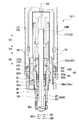
- FIG. 1 is a longitudinal sectional view of a particle sensor according to Example 1.
- FIG. 1 is an enlarged vertical sectional view of the fine particle sensor as viewed from the side rotated 90 degrees around the axis line.
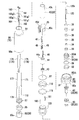
- 1 is an exploded perspective view of a fine particle sensor according to Example 1.
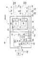
- FIG. 1 is a schematic diagram of a particulate detection system according to Example 1.
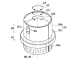
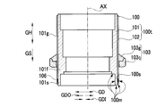
- FIG. 3 is a perspective view of an insulating spacer according to Embodiment 1.
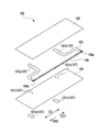
- FIG. It is a longitudinal cross-sectional view of the insulating spacer. It is the disassembled perspective view which expand
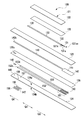
- 1 is a perspective view of a ceramic element according to Example 1.
- FIG. It is a disassembled perspective view of the ceramic element.
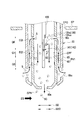
- 2 is an explanatory diagram of a particle sensor according to Example 1.
- FIG. 3 is a flowchart illustrating a flow of particle detection according to the first embodiment. 6 is a flowchart showing a flow of
- FIG. 1 is a longitudinal sectional view of a particle sensor 10 included in the particle detection system 1 according to the first embodiment.
- 2 is an enlarged cross-sectional view of the particle sensor 10
- FIG. 1 is an enlarged vertical cross-sectional view seen from the side rotated 90 degrees around the axis AX.
- FIG. 3 is an exploded perspective view of the particle sensor 10.
- FIG. 4 is a schematic diagram of the particulate detection system 1 according to the first embodiment. However, in FIG. 4, the circuit unit 200 included in the particle detection system 1 is mainly illustrated, and only a part of the particle sensor 10 (the electric wire 161 and the like) is illustrated. *
- the side (downward in FIG. 1) on which the gas intake pipe 25 is arranged is the tip side GS, and the wires 161, 163 on the opposite side, etc.
- the side (upward in FIG. 1) from which the is extended is defined as a base end side GK.
- the fine particle detection system 1 detects the amount of fine particles S (soot etc.) contained in exhaust gas (measured gas) EG flowing through an exhaust pipe (vent pipe) EP of an internal combustion engine (engine).
- the fine particle detection system 1 includes a fine particle sensor 10 and a circuit unit 200 (see FIGS. 1 and 4). *
- the particulate sensor 10 is attached to a metal exhaust pipe EP having a ground potential PVE (see FIG. 1). Specifically, a gas intake pipe 25 that forms the tip side portion of the inner metal fitting 20 in the particulate sensor 10 is disposed in the exhaust pipe EP through an attachment opening EPO provided in the exhaust pipe EP. Then, among the exhaust gas EG flowing through the exhaust pipe EP, ions CP are attached to the fine particles S in the intake gas EGI taken into the gas intake pipe 25 from the gas intake port 65c to form charged fine particles SC. Together with the input gas EGI, the gas is discharged from the gas discharge port 60e to the exhaust pipe EP (see FIG. 10). *
- the fine particle sensor 10 includes an inner metal fitting 20 having a gas intake pipe 25, an outer metal fitting 70, an insulating spacer 100, a ceramic element 120, six electric wires 161, 163, 171, 173, 175, 177 and the like (see FIG. 1 to FIG. 3). *
- the inner metal fitting 20 is electrically connected to the inner circuit case 250 or the like having the first potential PV1 in the circuit unit 200 described later via the inner outer conductors 161g1 and 163g1 of the electric wires 161 and 163 described later.
- the first potential PV1 is different from the ground potential PVE.
- the inner metal fitting 20 includes a main metal fitting 30, an inner cylinder 40, an inner cylinder connecting metal fitting 50, and a gas intake pipe 25 (an inner protector 60 and an outer protector 65). *
- the metal shell 30 is a cylindrical and stainless steel member extending in the longitudinal direction GH.
- the metal shell 30 has an annular flange portion 31 that bulges outward in the radial direction.
- a cup-shaped metal cup 33 is disposed inside the metal shell 30.
- a hole is formed in the bottom of the metal cup 33, and a ceramic element 120 described later is inserted into the hole.
- a filling layer 35 and a second powder filling layer 36 and a cylindrical ceramic sleeve 37 made of alumina are arranged.
- the ceramic holder 34 and the first powder filling layer 35 are located in the metal cup 33.
- the caulking portion 30kk on the most proximal side GK of the metal shell 30 is caulked inward in the radial direction to press the ceramic sleeve 37 to the distal end GS via the caulking ring 38.
- the metal shell 30 has a male screw portion 30n between the flange portion 31 and the tip portion 30s.
- a spacer retaining ring 32 that engages an insulating spacer 100 described later via a wire packing 39 is screwed to the male screw portion 30n.
- the thick portion 101f of the spacer body 101 of the insulating spacer 100 is sandwiched between the flange portion 31 of the metal shell 30 and the spacer retaining ring 32, and the metal shell 30 and the metal shell 30 are interposed via the insulating spacer 100 as will be described later.
- the ceramic element 120 and the like held thereby are fixed to the mounting bracket 80. *
- the inner cylinder 40 is a cylindrical and stainless steel member extending in the longitudinal direction GH.
- the distal end portion 40s of the inner cylinder 40 is fitted on the proximal end side portion 30k of the metal shell 30, and is laser welded to the proximal end side portion 30k.
- an insulating holder 43 Inside the inner cylinder 40, an insulating holder 43, a first separator 44, and a second separator 45 are arranged in order from the distal end side GS to the proximal end side GK.
- the insulating holder 43 is cylindrical and made of an insulator, and is in contact with the ceramic sleeve 37 from the base end side GK.
- the ceramic element 120 is inserted into the insulating holder 43.
- the first separator 44 is made of an insulator and has an insertion hole 44c.
- the ceramic element 120 is inserted into the insertion hole 44c, and the tip side portion of the discharge potential terminal 46 is accommodated.
- a discharge potential terminal 46 is in contact with a discharge potential pad 135 (see FIGS. 8 and 9) described later of the ceramic element 120.
- the second separator 45 is made of an insulator and has a first insertion hole 45c and a second insertion hole 45d.
- a proximal end portion of the discharge potential terminal 46 accommodated in the first insertion hole 45c and a distal end portion of a discharge potential lead wire 162 to be described later are connected in the first insertion hole 45c.
- the element base end portion 120k of the ceramic element 120 is disposed in the second insertion hole 45d, and the auxiliary potential terminal 47, the 2-1 heater terminal 48, and the 2-2 heater terminal 49 are insulated from each other. It is housed in the state where it was done.
- the auxiliary potential terminal 47 contacts the auxiliary potential pad 147 of the ceramic element 120
- the 2-1 heater terminal 48 contacts the 2-1 heater pad 156 of the ceramic element 120.
- the 2-2 heater terminal 49 is in contact with the 2-2 heater pad 158 of the ceramic element 120 (see FIGS. 1, 2, 8, and 9). *
- an auxiliary potential lead wire 164, a 2-1 heater lead wire 174, and a 2-2 heater lead wire 176 which will be described later, are arranged in the second insertion hole 45d.
- the auxiliary potential terminal 47 and the auxiliary potential lead wire 164 are connected, the 2-1 heater terminal 48 and the 2-1 heater lead wire 174 are connected, and the 2-2 heater terminal. 49 and the 2-2 heater lead wire 176 are connected.
- the inner cylinder connection fitting 50 is a member made of stainless steel and is fitted on the proximal end portion 40k of the inner cylinder 40 while surrounding the proximal end portion of the second separator 45, and the distal end portion 50s of the inner cylinder connection fitting 50 is Laser welding is performed on the base end portion 40 k of the inner cylinder 40.
- the four electric wires 161, 163, 173, and 175 except for the electric wires 171 and 177 are inserted into the inner cylinder connection fitting 50, respectively.
- inner outer conductors 161g1 and 163g1 of electric wires 161 and 163 of a triple coaxial cable to be described later are connected to the inner tube connection fitting 50. *
- the gas intake pipe 25 includes an inner protector 60 and an outer protector 65.
- the inner protector 60 is a bottomed cylindrical and stainless steel member
- the outer protector 65 is a cylindrical and stainless steel member.
- the outer protector 65 is arranged around the inner protector 60 in the radial direction.
- the inner protector 60 and the outer protector 65 are fitted on the distal end portion 30s of the metal shell 30, and are laser-welded to the distal end portion 30s.
- the gas intake pipe 25 surrounds the tip side portion of the ceramic element 120 protruding from the metal shell 30 to the tip side GS from the outside in the radial direction, and protects the ceramic element 120 from water droplets and foreign matters, while the exhaust gas EG is ceramic. Guide around the element 120.
- a plurality of rectangular gas inlets 65 c for taking the exhaust gas EG flowing through the exhaust pipe EP into the outer protector 65 are formed at the front end side portion of the outer protector 65. Further, in the inner protector 60, the intake gas EGI taken into the outer protector 65 out of the exhaust gas EG flowing through the exhaust pipe EP is further introduced into the inner protector 60. A plurality of circular first inner introduction holes 60c are formed. Further, a plurality of triangular second inner introduction holes 60 d are also formed at the tip side portion of the inner protector 60. Further, a circular gas discharge port 60e for discharging the intake gas EGI to the exhaust pipe EP is formed at the bottom of the inner protector 60. The distal end portion 60s of the inner protector 60 including the gas discharge port 60e protrudes from the distal end opening portion 65s of the outer protector 65 to the distal end side GS. *
- the intake and exhaust of the exhaust gas EG to the inner protector 60 and the outer protector 65 when the particulate sensor 10 is used will be described with reference to FIG.
- the exhaust gas EG circulates in the exhaust pipe EP from left to right.
- the flow velocity increases outside the gas discharge port 60e of the inner protector 60, and a negative pressure is generated near the gas discharge port 60e due to the venturi effect. . *
- the intake gas EGI taken into the inner protector 60 by this negative pressure is discharged from the gas discharge port 60e to the exhaust pipe EP.
- the exhaust gas EG around the gas inlet 65c of the outer protector 65 is taken into the outer protector 65 from the gas inlet 65c, and further inside the inner protector 60 through the first inner introduction hole 60c of the inner protector 60. Incorporated.
- the intake gas EGI in the inner protector 60 is discharged from the gas discharge port 60e.
- an air flow of the intake gas EGI that flows from the first inner introduction hole 60c on the base end side GK toward the gas discharge port 60e on the front end side GS is generated, as indicated by a broken line arrow. *
- the outer metal fitting 70 is cylindrical and made of metal, surrounds the inner circumference of the inner metal fitting 20 in a state of being separated from the inner metal fitting 20, and is an exhaust pipe having a ground potential PVE. Attached to the EP is set to the ground potential PVE.
- the outer metal fitting 70 is composed of an attachment metal 80 and an outer cylinder 90.
- the mounting bracket 80 is a cylindrical member extending in the longitudinal direction GH and made of stainless steel.
- the mounting bracket 80 is disposed around the radial direction of the distal end side portion of the main metal shell 30 and the inner cylinder 40 of the inner metal fitting 20 and is separated from these.
- the mounting bracket 80 has a flange portion 81 that bulges outward in the radial direction and forms an external hexagonal shape.
- a stepped portion 83 having a stepped shape is provided inside the mounting bracket 80.
- a male screw (not shown) used for fixing to the exhaust pipe EP is formed on the outer periphery of the distal end side portion 80s of the distal end side GS from the flange portion 81 of the mounting bracket 80.
- the fine particle sensor 10 is attached to a metal mounting boss BO, which is separately fixed to the exhaust pipe EP, by the male screw of the tip side portion 80s, and is fixed to the exhaust pipe EP via the mounting boss BO ( (See FIG. 1). *
- An insulating spacer 100 described later is disposed between the outer metal fitting 70 and the inner metal fitting 20, more specifically, between the mounting metal fitting 80 and the metal shell 30.
- the caulking portion 80kk on the most proximal side GK of the mounting bracket 80 is caulked to the radially inner GDI, and the annular protrusion of the insulating spacer 100 is interposed via the wire packing 87, the pressing sleeve 110, and the powder filler 115.
- the insulating spacer 100 is fixed to the mounting bracket 80 by pressing 103 to the tip side GS and press-contacting the stepped portion 83 of the mounting bracket 80. *
- the outer cylinder 90 is a cylindrical member extending in the longitudinal direction GH and is a stainless steel member.
- the distal end portion 90s of the outer cylinder 90 is fitted on the proximal end side portion 80k of the mounting bracket 80, and is laser welded to the proximal end side portion 80k.
- An outer cylinder connection fitting 95 is arranged inside the small diameter portion 91 located on the base end side GK in the outer cylinder 90, and a fluoro rubber grommet 97 is arranged on the base end side GK.
- Six electric wires 161, 163, 171, 173, 175, and 177, which will be described later, are inserted into the outer tube connecting fitting 95 and the grommet 97, respectively.
- the outer outer conductors 161g2 and 163g2 of the electric wires 161 and 163 of the triple coaxial cable described later are connected to the outer tube connection fitting 95, respectively.
- the outer cylinder connection fitting 95 is reduced in diameter in the radial direction by caulking together with the small diameter portion 91 of the outer cylinder 90, whereby the outer cylinder connection fitting 95 and the grommet 97 are fixed in the small diameter portion 91 of the outer cylinder 90. ing. *
- the insulating spacer 100 has a cylindrical shape extending in the longitudinal direction GH, and is a member mainly made of alumina. As described above, the insulating spacer 100 is interposed between the inner metal fitting 20 and the outer metal fitting 70 to electrically insulate them. Specifically, it is arranged between the front end side portions of the metal shell 30 and the inner cylinder 40 of the inner metal fitting 20 and the front end side portions of the mounting metal fitting 80 and the outer cylinder 90 of the outer metal fitting 70 (FIG. 1). reference). *
- the insulating spacer 100 includes a substantially cylindrical tubular portion 100t and an annular projecting portion 103 projecting annularly from the tubular portion 100t to the radially outer side GDO (see FIGS. 5 and 6).
- the tip side GS portion is a gas contact portion 100s (see FIGS. 1 and 2).
- the gas contact portion 100s has a gas contact surface 100m that is exposed in the exhaust pipe EP (facing the exhaust pipe EP) and is in contact with the exhaust gas EG in a state where the particulate sensor 10 is mounted on the exhaust pipe EP. (See FIGS. 1 and 6). *
- the cylindrical portion 100t includes a cylindrical spacer main body 101 made of alumina, and a layered heater portion 102 wound around an outer peripheral surface 101g forming a cylindrical surface of the spacer main body 101.
- the layered heater portion 102 is wound around the outer peripheral surface 101g of the spacer body 101 so that both ends in its circumferential direction do not overlap each other, and forms a single cylindrical shape (C-shaped cross section).
- a portion near the distal end GS in the longitudinal direction GH along the axis AX includes a thick portion 101f having a thicker thickness and a thin distal portion 101s located on the distal end GS than the thick portion 101s.
- the annular projecting portion 103 is airtightly fitted to the layered heater portion 102 and projects toward the radially outer side GDO of the insulating spacer 100. *
- the layered heater section 102 includes a layered spacer heater 105, an insulating base layer 108 made of alumina located inside thereof, and an insulating cover layer made of alumina located outside the spacer heater 105. 109.
- the spacer heater 105 includes a layered heating resistor 106 made of tungsten and a heater lead 107.
- the heater lead portion 107 includes a lead main body portion 107p extending from both ends of the heating resistor 106, a terminal pad 107m exposed on the surface of the layered heater portion 102, a cover insulating layer 109 and the lead main body portion 107p and the terminal pad.
- the via conductor 107v is electrically connected to 107m. *
- the heating resistor 106 has a meander shape (zigzag shape) and has a form extending in the circumferential direction CD of the insulating spacer 100.
- the heating resistor 106 one end 106p located on one side CD1 and the other end 106q located on the other side CD2 are wound around the spacer body 101 as shown in FIG. Opposing and adjoining in the circumferential direction CD.
- the heating resistor 106 is disposed inside the gas contact portion 100s of the insulating spacer 100 (see FIGS. 5 and 6).
- the heating resistor 106 of the spacer heater 105 to generate heat, the heat of the heating resistor 106 is transmitted to the gas contact portion 100s, and the gas contact surface 100m of the gas contact portion 100s can be appropriately heated. it can.
- the heating resistor 106 of the spacer heater 105 is covered with the insulating cover layer 109 and embedded in the insulating spacer 100. Thereby, it is possible to prevent the exhaust gas EG from coming into contact with the heating resistor 106. For this reason, foreign matter (soot, water droplets, etc.) contained in the exhaust gas EG adheres to the heating resistor 106, so that it is impossible to properly carry out the energization to the spacer heater 105 or the heating resistor 106 deteriorates. Can be suppressed. Therefore, even when the fine particle sensor 10 is used for a long period of time, the heating performance by the spacer heater 105 can be maintained satisfactorily. *
- the annular projecting portion 103 is an annular shape made of alumina, and a ceramic ring 103c fitted on the cylindrical portion 100t (specifically, the layered heater portion 102 provided on the outer periphery of the spacer main body 101) and the layered heater portion. And a glass seal portion 103g made of glass that is hermetically fixed to 102.
- the annular projecting portion 103 is directed toward the distal end GS via the wire packing 87, the pressing sleeve 110, and the powder filler 115 by crimping the crimping portion 80 kk of the mounting bracket 80. And pressed against the stepped portion 83 of the mounting bracket 80.
- the insulating spacer 100 can be easily and airtightly fixed to the mounting bracket 80 by providing the insulating spacer 100 with the annular protrusion 103. *
- the insulating spacer 100 is formed as follows. Specifically, an unfired layered heater portion 102 including a heating resistor 106 and a lead main body portion 107p formed by pattern printing is wound around the outer periphery of the calcined spacer body 101 and fired. Thereafter, the ceramic ring 103c is externally fitted to this, and this is hermetically fixed with glass to provide a glass seal portion 103g. Thereby, the insulating spacer 100 is formed. *
- the two heater lead portions 107 of the layered heater portion 102 of the insulating spacer 100 are connected to heater lead wires 172 and 178, which are the core wires of the single-core electric wires 171 and 177, respectively.
- the connection terminals 181 and 182 brazed to the terminal pads 107m and 107m hold and conduct the tip portions of the heater lead wire 172 of the electric wire 171 and the heater lead wire 178 of the electric wire 177, respectively.
- the ceramic element 120 has a plate-like insulating ceramic base 121 made of alumina extending in the longitudinal direction GH (see FIGS. 8 and 9).
- a discharge electrode body 130, an auxiliary electrode body 140, and an element heater 150 are embedded in the ceramic base 121, and these are integrally sintered with the ceramic base 121.
- the ceramic substrate 121 is formed by laminating three ceramic layers 122, 123, and 124 made of alumina derived from an alumina green sheet, and two insulating coatings made of alumina formed by printing between these layers. Layers 125 and 126 are interposed, respectively. Among these, the ceramic layer 122 and the insulating coating layer 125 are shorter than the ceramic layers 123 and 124 and the insulating coating layer 126 in the longitudinal direction GH on the distal end side GS and the proximal end side GK, respectively.
- the discharge electrode body 130 is disposed between the insulating coating layer 125 and the ceramic layer 123.
- the auxiliary electrode body 140 is disposed between the ceramic layer 123 and the insulating coating layer 126, and the element heater 150 is disposed between the insulating coating layer 126 and the ceramic layer 124. *
- the discharge electrode body 130 has a form extending in the longitudinal direction GH, and has a needle-like needle electrode portion 131 located on the distal end side GS, a discharge potential pad 135 located on the proximal end side GK, and a gap therebetween. And a lead portion 133 connecting the two.
- the needle electrode part 131 is made of a platinum wire.
- the lead portion 133 and the discharge potential pad 135 are made of pattern-printed tungsten.
- the base end side portion 131 k of the needle electrode portion 131 and the entire lead portion 133 are embedded in the ceramic base 121.
- the tip side portion 131 s of the needle electrode portion 131 protrudes from the ceramic base 121 on the tip side GS of the ceramic base 121 than the ceramic layer 122. Further, the discharge potential pad 135 is exposed in the base end side GK of the ceramic base 121 relative to the ceramic layer 122. The discharge potential pad 135 contacts the discharge potential terminal 46 in the insertion hole 44c of the first separator 44 as described above. *
- the auxiliary electrode body 140 has a form extending in the longitudinal direction GH, is formed by pattern printing, and is entirely embedded in the ceramic substrate 121.
- the auxiliary electrode body 140 includes a rectangular auxiliary electrode portion 141 located on the distal end side GS and a lead portion 143 connected to the auxiliary electrode portion 141 and extending to the proximal end side GK.
- the base end portion 143k of the lead portion 143 is connected to the conductive pattern 145 formed on one main surface 124a of the ceramic layer 124 through the through hole 126c of the insulating coating layer 126.
- the conductive pattern 145 is connected to an auxiliary potential pad 147 formed on the other main surface 124 b of the ceramic layer 124 through a through-hole conductor 146 formed through the ceramic layer 124.
- the auxiliary potential pad 147 contacts the auxiliary potential terminal 47 in the second insertion hole 45d of the second separator 45 as described above.
- the element heater 150 is formed by pattern printing, and is entirely embedded in the ceramic substrate 121.
- the element heater 150 is located at the distal end GS and heats the ceramic element 120, and a pair of heater leads 152 and 153 connected to both ends of the heating resistor 151 and extending to the proximal end GK. Consists of.
- the base end portion 152k of one heater lead portion 152 is connected to a 2-1 heater pad 156 formed on the other main surface 124b of the ceramic layer 124 via a through-hole conductor 155 penetratingly formed in the ceramic layer 124. Connected. As described above, the 2-1 heater pad 48 comes into contact with the 2-1 heater pad 156 in the second insertion hole 45d of the second separator 45.
- the base end portion 153k of the other heater lead portion 153 is a second-second heater pad formed on the other main surface 124b of the ceramic layer 124 via a through-hole conductor 157 penetrating the ceramic layer 124. 158. As described above, the second-second heater terminal 49 contacts the second-second heater pad 158 in the second insertion hole 45d of the second separator 45.
- the electric wires 161, 163, 171, 173, 175, and 177 will be described (see FIGS. 1 and 3).
- two wires 161 and 163 are triple coaxial cables (triaxial cables), and the remaining four wires 171, 173, 175, and 177 are small-diameter, single-core insulated wires.
- the electric wire 161 has a discharge potential lead wire 162 as a core wire (center conductor), and the discharge potential lead wire 162 is a discharge potential terminal 46 in the first insertion hole 45c of the second separator 45 as described above. Connected to.
- the electric wire 163 has an auxiliary potential lead wire 164 as a core wire (center conductor), and the auxiliary potential lead wire 164 is connected to the auxiliary potential terminal 47 in the second insertion hole 45 d of the second separator 45. .
- the inner inner outer conductors 161g1 and 163g1 are connected to the inner cylinder connecting metal fitting 50 of the inner metal fitting 20, and are set to the first potential PV1.
- the outer outer conductors 161g2 and 163g2 on the outer side are connected to an outer tube connection fitting 95 that is electrically connected to the outer fitting 70, and are set to the ground potential PVE. *
- the electric wire 171 has a heater lead wire 172 as a core wire.
- the electric wire 177 has a heater lead 178 as a core wire.
- the heater lead wires 172 and 178 are connected to the two heater lead portions 107 (specifically, the terminal pads 107m and 107m) of the layered heater portion 102 of the insulating spacer 100 through the connection terminals 181 and 182, respectively. It is connected to the.
- the electric wire 173 has a 2-1 heater lead wire 174 as a core wire.
- the 2-1 heater lead wire 174 is connected to the 2-1 heater terminal 48 in the second insertion hole 45d of the second separator 45.
- the electric wire 175 has a 2-2 heater lead wire 176 as a core wire.
- the 2-2 heater lead wire 176 is connected to the 2-2 heater terminal 49 in the second insertion hole 45d of the second separator 45. *
- the circuit unit 200 As shown in FIG. 4, the circuit unit 200 is connected to the electric wires 161, 163, 171, 173, 175, and 177 of the particle sensor 10, and drives the particle sensor 10 and detects a signal current Is described later. .
- the circuit unit 200 includes an ion source power supply circuit 210, an auxiliary electrode power supply circuit 240, and a measurement control circuit 220. *
- the ion source power supply circuit 210 includes a first output terminal 211 having a first potential PV1 and a second output terminal 212 having a second potential PV2.
- the second potential PV2 is set to a positive high potential with respect to the first potential PV1.
- the auxiliary electrode power circuit 240 has an auxiliary first output terminal 241 that is set to the first potential PV1 and an auxiliary second output terminal 242 that is set to the auxiliary electrode potential PV3.
- the auxiliary electrode potential PV3 is a positive DC high potential with respect to the first potential PV1, but is lower than the peak potential of the second potential PV2. *
- the measurement control circuit 220 includes a signal current detection circuit 230, a first heater energization circuit 223, a second heater energization circuit 225, and a microprocessor 221.
- the signal current detection circuit 230 includes a first input terminal 231 that is set to the first potential PV1 and a second input terminal 232.
- the signal current detection circuit 230 detects the signal current Is flowing between the first input terminal 231 and the second input terminal 232.
- the first potential PV1 is higher than the ground potential PVE by an offset voltage Voffset (specifically, 0.5V).
- Voffset specifically, 0.5V
- the second input terminal 232 is set to a potential that is higher than the ground potential PVE by an offset voltage V offset (specifically, 0.5 V).
- the first heater energization circuit 223 includes a 1-1 heater energization end 223a connected to the heater lead wire 172 of the electric wire 171 and a 1-2 heater energization end 223b set to the ground potential PVE.
- the first heater energizing circuit 223 energizes the spacer heater 105 of the insulating spacer 100 by PWM control to cause the heating resistor 106 of the spacer heater 105 to generate heat.
- the second heater energization circuit 225 is connected to the 2-1 heater energization end 225a connected to the 2-1 heater lead 174 of the electric wire 173 and the 2-2 heater lead 176 of the electric wire 175.
- the second heater energization circuit 225 energizes the element heater 150 of the ceramic element 120 by PWM control, and causes the heat generating resistor 151 of the element heater 150 to generate heat.
- the ion source power supply circuit 210 and the auxiliary electrode power supply circuit 240 are surrounded by an inner circuit case 250 having a first potential PV1.
- the inner circuit case 250 encloses and surrounds the secondary iron core 271b of the insulating transformer 270 and is electrically connected to the inner outer conductors 161g1 and 163g1 of the electric wires 161 and 163, which are set to the first potential PV1.
- the insulation transformer 270 has an iron core 271 separated into a primary iron core 271a wound around the primary coil 272 and a secondary iron core 271b wound around the power circuit coil 273 and the auxiliary electrode power supply coil 274. Configured. Among these, the primary side iron core 271a is conducted to the ground potential PVE, and the secondary side iron core 271b is conducted to the first potential PV1. *
- the ion source power supply circuit 210, the auxiliary electrode power supply circuit 240, the inner circuit case 250, and the measurement control circuit 220 are surrounded by an outer circuit case 260 having a ground potential PVE.
- the outer circuit case 260 houses and surrounds the primary iron core 271a of the insulating transformer 270, and is electrically connected to the outer outer conductors 161g2 and 163g2 of the electric wires 161 and 163, which are set to the ground potential PVE.
- the measurement control circuit 220 includes a regulator power source PS.
- the regulator power supply PS is driven by an external battery BT through the power supply wiring BC.
- a part of the power input to the measurement control circuit 220 through the regulator power supply PS is distributed to the ion source power supply circuit 210 and the auxiliary electrode power supply circuit 240 through the isolation transformer 270.
- the measurement control circuit 220 includes a microprocessor 221 and can communicate with a control unit ECU that controls the internal combustion engine via a communication line CC.
- the measurement result (signal current) of the signal current detection circuit 230 described above is used.
- a signal such as (Is magnitude) can be transmitted to the control unit ECU. *
- the discharge electrode body 130 of the ceramic element 120 is connected and connected to the second output terminal 212 of the ion source power supply circuit 210 via the discharge potential lead wire 162 of the electric wire 161, and is set to the second potential PV2. 4, FIG. 8, FIG. 9).
- the auxiliary electrode body 140 of the ceramic element 120 is connected to and connected to the auxiliary second output terminal 242 of the auxiliary electrode power supply circuit 240 via the auxiliary potential lead 164 of the electric wire 163, and is set to the auxiliary electrode potential PV3.
- the inner metal fitting 20 is connected to the inner circuit case 250 and the like through the inner outer conductors 161g1 and 163g1 of the electric wires 161 and 163, and is set to the first potential PV1 (FIGS. 1, 3, and 3). 4).
- the outer metal fitting 70 is connected to the outer circuit case 260 and the like through the outer outer conductors 161g2 and 163g2 of the electric wires 161 and 163, and is set to the ground potential PVE. *
- a positive high voltage is applied to the needle electrode portion 131 of the discharge electrode body 130 from the ion source power supply circuit 210 of the circuit portion 200 through the discharge potential lead wire 162, the discharge potential terminal 46, and the discharge potential pad 135 of the electric wire 161.
- a second potential PV2 having a voltage is applied.
- an air discharge specifically, corona discharge is generated between the needle-like tip 131ss of the needle-like electrode part 131 and the inner protector 60 having the first potential PV1, and the needle-like tip 131ss Ions CP are generated around (see FIG. 10).
- the exhaust gas EG is taken into the inner protector 60 by the action of the gas intake pipe 25, and in the vicinity of the ceramic element 120, the flow of the intake gas EGI from the proximal end GK toward the distal end GS is generated. Has occurred. Therefore, the generated ions CP adhere to the fine particles S in the intake gas EGI. As a result, the fine particles S become positively charged charged particles SC, flow toward the gas discharge port 60e together with the intake gas EGI, and are discharged to the exhaust pipe EP (see FIG. 10). *
- the auxiliary electrode portion 141 of the auxiliary electrode body 140 has a predetermined potential (from the auxiliary electrode power circuit 240 of the circuit portion 200 through the auxiliary potential lead wire 164 of the electric wire 163, the auxiliary potential terminal 47, and the auxiliary potential pad 147).
- the auxiliary electrode potential PV3 set to 100 to 200 V (positive DC potential) is applied.
- repulsive force directed from the auxiliary electrode portion 141 toward the radially inner protector 60 (collecting electrode) is applied to the floating ions CPF that have not adhered to the fine particles S among the generated ions CP.
- floating ions CPF are attached to each part of the collection electrode (inner protector 60) to assist the collection (see FIG. 10).
- the floating ions CPF can be reliably collected, and even the floating ions CPF are prevented from being discharged from the gas outlet 60e.
- the signal current detection circuit 230 detects a signal (signal current Is) corresponding to the charge amount of the discharged ions CPH attached to the charged particulate SC discharged from the gas discharge port 60 e. . Thereby, the amount (concentration) of the fine particles S contained in the exhaust gas EG can be detected.
- the ions CP generated by the air discharge are attached to the fine particles S contained in the exhaust gas EG taken into the gas intake pipe 25, and the charged fine particles SC are charged.
- the amount of fine particles S in the exhaust gas EG is detected by using a signal current Is that is generated and flows in accordance with the amount of charged fine particles SC between the first potential PV1 and the ground potential PVE.
- the fine particle sensor 10 includes an element heater 150 in the ceramic element 120.
- the 2-1 heater pad 156 of the element heater 150 is connected to the second heater energizing circuit 225 of the circuit unit 200 via the 2-1 heater terminal 48 and the 2-1 heater lead 174 of the electric wire 173.
- the 2-2 heater pad 158 of the element heater 150 is connected to the 2-2 heater pad 49 of the second heater energizing circuit 225 via the 2-2 heater terminal 49 and the 2-2 heater lead 176 of the electric wire 175. It is electrically connected to the heater energization end 225b.
- the heating resistor 151 of the element heater 150 is energized. Generates heat. Thereby, the ceramic element 120 can be heated to remove foreign matters (water droplets, soot, etc.) attached to the ceramic element 120, so that the insulation of the ceramic element 120 can be recovered or maintained.
- the insulating spacer 100 is in contact with the exhaust gas EG flowing through the exhaust pipe EP at the gas contact surface 100m. For this reason, foreign matters (for example, moisture and soot) contained in the exhaust gas EG may adhere to the gas contact surface 100 m of the insulating spacer 100. When such foreign matter adheres to the gas contact surface 100m, the insulating property of the insulating spacer 100 decreases, and the insulation between the inner metal fitting 20 that is set to the first potential PV1 and the outer metal fitting 70 that is set to the ground potential PVE. May decrease, and the amount of the particulates S contained in the exhaust gas EG may not be properly detected.
- the insulating spacer 100 is in contact with the exhaust gas EG flowing through the exhaust pipe EP at the gas contact surface 100m. For this reason, foreign matters (for example, moisture and soot) contained in the exhaust gas EG may adhere to the gas contact surface 100 m of the insulating spacer 100. When such foreign matter adheres to the gas contact surface 100m, the insulating property
- the particle sensor 10 of the first embodiment has a spacer heater 105 in the insulating spacer 100.
- One terminal pad 107 m of the spacer heater 105 is connected to the first-first heater energization end 223 a of the first heater energization circuit 223 via the connection terminal 181 and the heater lead wire 172 of the electric wire 171. Further, the other terminal pad 107 m of the spacer heater 105 is connected via the connection terminal 182 and the heater lead wire 178 of the electric wire 177.
- the first heater energization circuit 223 is connected to the 1-2 heater energization end 223b. As a result, the first heater energization circuit 223 can energize the spacer heater 105 (heating resistor 106).
- the heating resistor 106 of the spacer heater 105 generates heat.
- the gas contact part 100s (gas contact surface 100m) of the insulating spacer 100 can be heated, and foreign substances (water, soot, etc.) adhering to the gas contact surface 100m of the gas contact part 100s can be removed.
- the insulating property of the insulating spacer 100 insulating property of the gas contact surface 100m
- a method for recovering the insulation between the inner metal fitting 20 and the outer metal fitting 70 in the first embodiment will be described in detail.
- the degree of insulation between the inner metal fitting 20 (first potential PV1) and the outer metal fitting 70 (ground potential PVE) is within an allowable range. Inspect whether or not. Specifically, as described above, the offset voltage V offset (specifically, 0.5 V) is applied between the inner metal fitting 20 (first potential PV1) and the outer metal fitting 70 (ground potential PVE). The For this reason, a leakage current Im flowing between the inner metal fitting 20 and the outer metal fitting 70 is generated according to the degree of insulation between the inner metal fitting 20 and the outer metal fitting 70. This leakage current Im is detected by the signal current detection circuit 230.
- the microprocessor 221 determines whether or not the magnitude of the leakage current Im detected by the signal current detection circuit 230 is within an allowable range (specifically, whether it is equal to or less than a preset reference value Ims (threshold)). )). In the first embodiment, the “degree of insulation” is indicated by the magnitude of the leakage current Im.
- the allowable range of the degree of insulation between the inner metal fitting 20 and the outer metal fitting 70 is determined by the fine particle detection system 1 by the fine particles S in the exhaust gas EG. It is set in the range of the degree of insulation that can appropriately detect the amount of. When foreign matter such as water droplets or soot adheres to the gas contact surface 100m of the gas contact portion 100s of the insulating spacer 100, the degree of insulation between the inner metal fitting 20 and the outer metal fitting 70 is not within an allowable range. Specifically, it can be determined that the leakage current Im is larger than the reference value Ims (threshold). *
- the degree of insulation between the inner metal fitting 20 and the outer metal fitting 70 is not within the allowable range (specifically, the leakage current Im is smaller than the reference value Ims.
- the first heater energizing circuit 223 energizes the spacer heater 105 to cause the heating resistor 106 to generate heat, and heats the gas contact portion 100s (gas contact surface 100m) of the insulating spacer 100.
- the heater is energized. More specifically, the temperature at which foreign matter (water, soot, etc.) adhering to the gas contact surface 100m is removed when the leakage current Im is determined to be larger than the reference value Ims after the engine is started.
- the heater energization is performed to raise the temperature of the spacer heater 105 to a temperature (specifically, a temperature in the range of 500 to 600 ° C.).
- a temperature specifically, a temperature in the range of 500 to 600 ° C.
- the foreign matter (water, soot, etc.) adhering to the gas contact surface 100m of the insulating spacer 100 is removed, and the insulating property (gas contact) of the insulating spacer 100 which has been lowered due to the foreign matter adhering to the gas contact surface 100m. Insulating property of the surface 100 m is recovered.
- the particulate detection system 1 of the first embodiment when the heater energization is performed, when the particulate sensor 10 is subsequently driven, a constant cooling time tc is obtained after the heater energization is completed. After the elapse of time, the particle sensor 10 is driven. After the heater energization is completed, the temperature of the insulating spacer 100 is lowered when a certain cooling time tc elapses, so that the volume resistivity (volume resistivity) of the insulating spacer 100 can be recovered. Thus, the insulating spacer 100 can appropriately electrically insulate between the inner metal fitting 20 and the outer metal fitting 70. Thereafter, by driving the particulate sensor 10, the amount of the particulate S in the exhaust gas EG can be detected appropriately. *
- the particulate sensor 10 is driven without waiting for the elapse of the cooling time tc. Thereby, the amount of fine particles S in the exhaust gas EG can be detected appropriately.
- the “certain cooling time tc” is a time period (for example, 10 minutes) in which the temperature of the insulating spacer 100 that has been heated by the heater energization is expected to decrease to a temperature before the heater energization. Is set to *
- the signal current Is is very small, but as described above, when it is determined that the leakage current Im is equal to or less than the reference value Ims, the amount of particulates is detected. Do. Alternatively, even when it is determined that the leakage current Im is larger than the reference value Ims, the foreign matter adhering to the gas contact surface 100m is removed by energization of the heater, and thereafter, after a certain cooling time tc has elapsed, the fine particles S The amount of detection is performed. Thereby, in the particulate detection system 1, since the minute signal current Is can be appropriately detected without being affected by the leakage current Im, the amount of the particulate S contained in the exhaust gas EG can be appropriately detected. . *
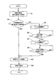
- FIG. 11 is a flowchart illustrating a flow of particle detection according to the first embodiment.
- the signal current detection circuit 230 is connected to the first input terminal 231 and the second input based on a command from the microprocessor 221 in step S1.
- a leakage current Im flowing between the input end 232, that is, between the inner metal fitting 20 (first potential PV1) and the outer metal fitting 70 (ground potential PVE) is detected.
- step S2 the microprocessor 221 determines whether or not the magnitude of the leakage current Im detected by the signal current detection circuit 230 is within an allowable range (specifically, not more than a preset reference value Ims). Whether or not there is). *
- step S3 If it is determined that the leakage current Im is equal to or less than the reference value Ims (YES), the process proceeds to step S3, and the microprocessor 221 drives the particulate sensor 10. Specifically, as described above, the ion source power supply circuit 210 and the auxiliary electrode power supply circuit 240 are driven to perform processes such as generating ions CP by corona discharge. *
- step S4 the process proceeds to step S4, and the amount of fine particles S contained in the exhaust gas EG is detected.
- the signal current detection circuit 230 detects a signal (signal current Is) corresponding to the charge amount of the discharged ions CPH. Thereby, the amount (concentration) of the fine particles S contained in the exhaust gas EG can be detected.
- step S2 if it is determined in step S2 that the leakage current Im is greater than the reference value Ims (NO), the process proceeds to step S5 and heater energization is started. Specifically, based on a command from the microprocessor 221, the first heater energization circuit 223 energizes the spacer heater 105 by PWM control, and foreign matter (water, soot, etc.) adhering to the gas contact surface 100m. The temperature of the spacer heater 105 is raised to a temperature at which the temperature is removed (specifically, a temperature in the range of 500 to 600 ° C.). *
- step S6 the microprocessor 221 determines whether or not a predetermined time has passed since the energization of the spacer heater 105 from the first heater energization circuit 223 (for example, from the first heater energization circuit 223 to the spacer heater 105). It is determined whether the energization time for the heater 105 has reached a preset constant energization time).
- the predetermined time is preferably set to a time necessary and sufficient for removing foreign matter adhering to the gas contact portion 100s, for example.
- step S6 If it is determined in step S6 that a predetermined time has elapsed from the start of energization (YES), the process proceeds to step S7, and the first heater energization circuit 223 is connected to the spacer heater 105 based on a command from the microprocessor 221. End energization. If it is determined in step S6 that the predetermined time has not elapsed since the start of energization of the spacer heater 105 (NO), the determination process in step S6 is repeated until the predetermined time has elapsed. By performing the processing of steps S5 to S7, heater energization is performed, and the foreign matter adhering to the gas contact surface 100m of the insulating spacer 100 is removed. *
- step S7 when the heater energization is completed by terminating energization of the spacer heater 105, the process proceeds to step S8, after the heater energization (energization of the spacer heater 105 by the first heater energization circuit 223) is completed. It is determined whether or not a certain cooling time tc has elapsed. If it is determined that the cooling time tc has not elapsed (NO), the determination process of step S8 is repeated until the cooling time tc has elapsed. Thereafter, when it is determined in step S8 that the cooling time tc has elapsed (YES), the process proceeds to steps S3 and S4, and the above-described processing is performed to detect the amount of fine particles S contained in the exhaust gas EG. *
- the degree of insulation between the inner metal fitting 20 and the outer metal fitting 70 is increased prior to the start of driving of the particulate sensor 10. It is inspected whether or not it is within an allowable range (specifically, whether or not the leakage current Im flowing between the inner metal fitting 20 and the outer metal fitting 70 is equal to or less than the reference value Ims).
- the particulate sensor 10 When it is determined that the degree of insulation is within an allowable range (specifically, the leakage current Im is equal to or less than the reference value Ims), the particulate sensor 10 is driven to detect the amount of particulate S. Do. Further, even when it is determined that the degree of insulation is not within the allowable range (specifically, the leakage current Im is larger than the reference value Ims), the foreign matter adhering to the gas contact surface 100m is removed by energizing the heater. Thereafter, the amount of fine particles S is detected after a certain cooling time tc has elapsed. Therefore, according to the particulate detection system 1 of the first embodiment, after the operation of the engine (internal combustion engine) is started, the amount of particulate S in the exhaust gas EG exhausted from the engine can be detected appropriately. . *
- microprocessor 221 and the signal current detection circuit 230 that perform the processes of steps S1 and S2 correspond to “insulation inspection means”. Further, the microprocessor 221, the ion source power supply circuit 210, and the auxiliary electrode power supply circuit 240 that perform the processing of step S3 correspond to “sensor driving means”. Further, the microprocessor 221 and the first heater energizing circuit 223 that perform the processes of steps S5 to S7 correspond to “heater energizing means”. *
- Example 2 of the present invention will be described.
- the second embodiment is different from the first embodiment in the flow of particulate detection (specifically, heater energization and subsequent processing) (therefore, the control program input to the microprocessor 221 is different). Others are the same. For this reason, it demonstrates centering on a different point from Example 1, and abbreviate
- the inner metal fitting 20 (first potential PV1) is connected. It is inspected whether the degree of insulation with the outer metal fitting 70 (ground potential PVE) is within an allowable range. Specifically, the signal current detection circuit 230 measures the leakage current Im (step T1 in FIG. 12), and the microprocessor 221 determines whether or not the magnitude of the measured leakage current Im is within an allowable range (specifically Specifically, it is determined whether or not it is equal to or less than a preset reference value Ims (threshold value) (step T2 in FIG. 12).
- the first heater energization circuit 223 When it is determined that the degree of insulation between the inner metal fitting 20 and the outer metal fitting 70 is not within the allowable range (specifically, the leakage current Im is larger than the reference value Ims), the first heater energization circuit 223 is used. Thus, the heater 105 is energized to energize the spacer heater 105 to heat the heating resistor 106 and heat the gas contact portion 100 s of the insulating spacer 100. However, in the second embodiment, heater energization (referred to as first heater energization) different from the heater energization in the first embodiment is performed. *
- the leakage current Im is larger than the reference value Ims after the engine operation is started
- First heater energization is performed to raise the temperature of the spacer heater 105 to a temperature (for example, a temperature in the range of 100 to 150 ° C.) (steps T5 to T7 in FIG. 12).
- a temperature for example, a temperature in the range of 100 to 150 ° C.
- the inner metal fitting is again used. It is inspected whether or not the degree of insulation between 20 and the outer metal fitting 70 is within an allowable range (specifically, whether or not the leakage current Im is equal to or less than the reference value Ims) (step of FIG. 12). T8 to T9).
- the first heater energization is the energization to the spacer heater 105.
- Second heater energization under different conditions is performed (steps T10 to T12 in FIG. 12). Specifically, the first heater energization circuit 223 energizes the spacer heater 105 to remove a foreign substance (soot, oil, etc.) that cannot be removed by the first heater energization attached to the gas contact surface 100m ( The temperature of the spacer heater 105 is increased to a temperature higher than the temperature by energization of the first heater (a temperature in the range of 500 to 600 ° C.). *
- the temperature of the insulating spacer 100 is increased, so that the volume resistivity (volume resistivity) is decreased.
- the temperature of the insulating spacer 100 is increased by energizing the first heater, if the foreign matter is removed from the gas contact surface 100m of the insulating spacer 100, the inner spacer 20 and the outer side are removed by the insulating spacer 100.
- the dimensions of the insulating spacer 100 (specifically, between the inner metal fitting 20 and the outer metal fitting 70 so that the electric insulation between the metal fitting 70 can be appropriately insulated (in other words, the leakage current Im is equal to or less than the reference value Ims).
- the thickness of the insulating spacer 100 interposed therebetween is ensured.
- Example 2 even if the particulate sensor 10 is driven quickly without waiting for the elapse of the cooling time after the first heater is energized, the volume resistivity corresponding to the temperature rise of the insulating spacer 100 is appropriately Without being affected by the decrease in the particle size).
- the insulation test is performed without waiting for the elapse of the cooling time after the first heater is energized, the inner metal fitting 20 and the outer metal fitting 70 that have been lowered due to water adhering to the gas contact surface 100m. It can be appropriately determined (without being affected by the decrease in volume resistivity accompanying the temperature rise of the insulating spacer 100) whether or not the insulation between them has recovered.
- the first cooling time for the first heater energization is set to “0”, and the insulation test is performed without waiting for the elapse of the cooling time after the first heater energization (see FIG. 12 (step T8), when it is determined that the degree of insulation is within the allowable range (specifically, the leakage current Im is equal to or less than the reference value Ims), the particulate sensor 10 is immediately driven ( In step T3 in FIG. 12, fine particle detection is performed (step T4 in FIG. 12). *
- the temperature rise of the insulating spacer 100 is larger than when the first heater energization is performed, and the volume resistivity (volume resistivity) of the insulating spacer 100 is decreased. growing. Therefore, immediately after the second heater is energized, there is a possibility that the insulating spacer 100 cannot properly electrically insulate the inner metal fitting 20 and the outer metal fitting 70. In such a case, after the second heater is energized, when the particulate sensor 10 is driven to detect the amount of particulate S in the exhaust gas EG, the amount of particulate S in the exhaust gas EG is appropriately set. There is a possibility that it cannot be detected. *
- the second cooling time t2 elapses after the second heater energization ends.
- the fine particle sensor 10 is driven.
- the second cooling time t2 elapses, so that the temperature of the insulating spacer 100 is lowered, so that the volume resistivity (volume resistivity) of the insulating spacer 100 can be recovered.
- the insulating spacer 100 can appropriately electrically insulate between the inner metal fitting 20 and the outer metal fitting 70.
- the particulate sensor 10 the amount of the particulate S in the exhaust gas EG can be detected appropriately.
- the “second cooling time t2” is “a cooling time set in accordance with the energization condition to the spacer heater 105 by the second heater energization (for example, the duty ratio of PWM control by the first heater energization circuit 223)”
- the cooling time is preset for the second heater energization.
- the “second cooling time t2” is a time during which the temperature of the insulating spacer 100, which has been heated by the second heater energization, is expected to decrease to a temperature before the second heater energization (for example, 10 Minutes).
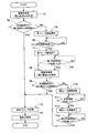
- FIG. 12 is a flowchart illustrating the flow of particle detection according to the second embodiment.
- step T14 indicated by a broken line in FIG. 12 is a process performed in Modification 1 described later, and is a process not performed in Example 2.
- the key switch (not shown) of the engine is turned on and the engine is started, the leakage current Im is detected in step T1 as in step S1 of the first embodiment.
- step T2 as in step S2 of the first embodiment, whether or not the magnitude of the leakage current Im is within an allowable range (specifically, whether or not it is equal to or less than a preset reference value Ims). Determine. *
- step T2 If it is determined in step T2 that the leakage current Im is equal to or less than the reference value Ims (YES), the process proceeds to step T3, and the particulate sensor 10 is driven as in step S3 of the first embodiment. Next, the process proceeds to step T4, and the amount of fine particles S contained in the exhaust gas EG is detected as in step S4 of the first embodiment.
- step T2 when it is determined in step T2 that the leakage current Im is larger than the reference value Ims (NO), the process proceeds to step T5, and the first heater energization is started. Specifically, based on a command from the microprocessor 221, the first heater energization circuit 223 energizes the spacer heater 105 by PWM control for executing the first heater energization and adheres to the gas contact surface 100m. The spacer heater 105 is heated up to a temperature at which the removed water is removed (for example, a temperature in the range of 100 to 150 ° C.).
- the effective voltage applied to the spacer heater 105 is “the temperature of the spacer heater 105 is a temperature at which water adhering to the gas contact surface 100 m is removed (for example, within a range of 100 to 150 ° C.).
- the duty ratio of the PWM control by the first heater energization circuit 223 is set so that the value becomes “a value that can be obtained as the temperature of the first heater”, and the first heater energization is executed.
- step T6 the microprocessor 221 determines whether or not a predetermined time has elapsed since the energization of the spacer heater 105 from the first heater energization circuit 223 (for example, from the first heater energization circuit 223 to the spacer heater 105). It is determined whether the energization time for the heater 105 has reached a preset first energization time).
- the predetermined time (first energization time) is preferably set to a time necessary and sufficient to evaporate water adhering to the gas contact portion 100s, for example. *
- step T6 If it is determined in step T6 that a predetermined time has elapsed from the start of energization (YES), the process proceeds to step T7, and the first heater energization circuit 223 supplies the spacer heater 105 to the spacer 105 based on a command from the microprocessor 221. End energization. If it is determined in step T6 that the predetermined time has not elapsed since the start of energization of the spacer heater 105 (NO), the determination process in step T6 is repeated until the predetermined time has elapsed. By performing the processing of steps T5 to T7, the first heater energization is performed, and water adhering to the gas contact surface 100m of the insulating spacer 100 is removed (evaporates). *
- step T7 when the first heater energization is completed by terminating the energization to the spacer heater 105, the process proceeds to step T8, and the leakage current Im is detected as in step T1 described above.
- step T9 the process proceeds to Step T9, and whether or not the magnitude of the detected leakage current Im is within an allowable range (specifically, whether or not it is equal to or less than a preset reference value Ims), as in Step T2 described above. )).
- an allowable range specifically, whether or not it is equal to or less than a preset reference value Ims
- step T9 If it is determined in step T9 that the leakage current Im is equal to or less than the reference value Ims (YES), the process proceeds to steps T3 and T4, and the above-described processing is performed to determine the amount of the particulates S contained in the exhaust gas EG. Detect. *
- step T9 if it is determined in step T9 that the leakage current Im is greater than the reference value Ims (NO), the process proceeds to step T10 and the second heater energization is started. Specifically, based on a command from the microprocessor 221, the first heater energization circuit 223 performs PWM control for executing the second heater energization (PWM having a duty ratio larger than that of the previous first heater energization).
- the temperature at which foreign matter (soot, oil, etc.) that cannot be removed by energizing the first heater energized to the gas contact surface 100m by energizing the spacer heater 105 (by control) is removed (temperature higher than energizing the first heater)
- the temperature of the spacer heater 105 is increased to a temperature in the range of 500 to 600 ° C.
- the effective voltage applied to the spacer heater 105 is “foreign matter (soot, oil, etc.) that cannot be removed by energizing the first heater attached to the gas contact surface 100 m of the temperature of the spacer heater 105.
- the duty ratio of PWM control by the first heater energizing circuit 223 is set so that the temperature becomes a temperature that can be removed (for example, a temperature within a range of 500 to 600 ° C.), and the second heater energization is performed. To do.
- the microprocessor 221 determines whether or not a predetermined time has elapsed since the energization of the spacer heater 105 from the first heater energization circuit 223 (for example, from the first heater energization circuit 223 to the spacer heater 105). It is determined whether the energization time to the heater 105 has reached a preset second energization time).
- the predetermined time (second energization time) is preferably set to a time necessary and sufficient for removing (burning out) soot adhering to the gas contact portion 100s, for example.
- step T11 If it is determined in step T11 that a predetermined time has elapsed since the start of energization (YES), the process proceeds to step T12, and the first heater energization circuit 223 supplies the spacer heater 105 to the spacer 105 based on a command from the microprocessor 221. End energization. If it is determined in step T11 that the predetermined time has not elapsed since the start of energization of the spacer heater 105 (NO), the determination process in step T11 is repeated until the predetermined time has elapsed.
- the second heater energization is performed, and soot and other foreign matters (foreign matters that could not be removed by the first heater energization) adhering to the gas contact surface 100m of the insulating spacer 100 are removed. Is done. Thereby, it is possible to recover the insulating property of the insulating spacer 100 (insulating property of the gas contact surface 100m), which has been deteriorated due to foreign matters such as soot adhering to the gas contact surface 100m.
- step T12 when the second heater energization is completed by ending energization to the spacer heater 105, the process proceeds to step T13, and whether or not the second cooling time t2 has elapsed after the second heater energization is terminated. judge. When it is determined that the second cooling time t2 has not elapsed (NO), the determination process of step T13 is repeated until the second cooling time t2 has elapsed. Thereafter, when it is determined that the second cooling time t2 has elapsed (YES), the process proceeds to steps T3 and T4, and the above-described processing is performed to detect the amount of the fine particles S contained in the exhaust gas EG. *
- the degree of insulation between the inner metal fitting 20 and the outer metal fitting 70 is increased prior to the start of driving of the particulate sensor 10. It is inspected whether or not it is within an allowable range (specifically, whether or not the leakage current Im flowing between the inner metal fitting 20 and the outer metal fitting 70 is equal to or less than the reference value Ims).
- the particulate sensor 10 When it is determined that the degree of insulation is within an allowable range (specifically, the leakage current Im is equal to or less than the reference value Ims), the particulate sensor 10 is driven to detect the amount of particulate S. Do. In addition, it is determined that the degree of insulation is not within the allowable range (specifically, the leakage current Im is greater than the reference value Ims), and after the first heater is energized, the degree of insulation is within the allowable range. In the case where it is determined that, the fine particle sensor 10 is then driven to detect the amount of the fine particles S. *
- the second heater is energized to remove foreign matter such as soot from the gas contact surface 100 m of the insulating spacer 100.
- the insulating property (volume resistivity) of the insulating spacer 100 is recovered by the elapse of the second cooling time t2, and then the particle sensor 10 is driven to detect the amount of the particle S. Therefore, according to the particulate detection system 301 of the second embodiment, after the operation of the engine (internal combustion engine) is started, the amount of the particulate S in the exhaust gas EG exhausted from the engine can be appropriately detected. . *
- the microprocessor 221 and the signal current detection circuit 230 that perform the processes of steps T1 and T2, and the microprocessor 221 and the signal current detection circuit 230 that perform the processes of steps T8 and T9 correspond to “insulation inspection means”. Further, the microprocessor 221, the ion source power supply circuit 210, and the auxiliary electrode power supply circuit 240 that perform the process of step T3 correspond to “sensor driving means”. Further, the microprocessor 221 and the first heater energizing circuit 223 that perform the processes of steps T5 to T7, and the microprocessor 221 and the first heater energizing circuit 223 that perform the processes of steps T10 to T12 correspond to “heater energizing means”. . *
- Modification 1 of the present invention will be described.
- the first modification is different from the second embodiment in part of the flow of particle detection (thus, the control program input to the microprocessor 221 is different), and the other is the same. For this reason, here, it demonstrates centering on a different point from Example 2, and abbreviate
- the first cooling time for the first heater energization is set to “0”, and after the first heater energization, the insulation test is performed without waiting for the elapse of the cooling time,
- the particle sensor 10 is driven promptly to perform particle detection. (See FIG. 12).
- the reason why such treatment is possible is that, in Example 2, even if the temperature of the insulating spacer 100 is increased by energization of the first heater, if foreign matter is removed from the gas contact surface 100m of the insulating spacer 100, the insulating spacer 100 is insulated.
- the dimensions of the insulating spacer 100 (specifically, the inner metal fitting 20 and the outer metal fitting 70 can be appropriately electrically insulated (in other words, the leakage current Im is equal to or less than the reference value Ims). This is because the thickness of the insulating spacer 100 interposed between the metal fitting 20 and the outer metal fitting 70 is secured.
- the size of the insulating spacer 100 (specifically, the thickness of the insulating spacer 100 interposed between the inner metal fitting 20 and the outer metal fitting 70) is “first.
- the temperature of the insulating spacer 100 is increased by energizing the heater, the insulating spacer 100 cannot properly electrically insulate between the inner metal fitting 20 and the outer metal fitting 70 even if foreign matter is removed from the gas contact surface 100m of the insulating spacer 100 ( In other words, the dimension is such a small dimension that the leakage current Im becomes larger than the reference value Ims.
- FIG. 12 is a flowchart showing the flow of particulate detection according to the first modification.
- step T7 when the first heater energization is terminated by terminating energization to the spacer heater 105 in step T7 as indicated by a broken line in FIG. It is determined whether or not the first cooling time t1 has elapsed since the end of energization of one heater. When it is determined that the first cooling time t1 has not elapsed (NO), the determination process of step T14 is repeated until the first cooling time t1 has elapsed. Thereafter, when it is determined that the first cooling time t1 has elapsed (YES), the process proceeds to step T8, and the leakage current Im is detected.
- step T9 if it is determined in step T9 that the detected leakage current Im is within the allowable range (specifically, it is equal to or less than a preset reference value Ims), the process proceeds to steps T3 and T4. The amount of fine particles S contained in the exhaust gas EG is detected. *
- the “first cooling time t1” is “the cooling time set according to the energization condition to the spacer heater 105 by the first heater energization (for example, the duty ratio of PWM control by the first heater energization circuit 223)”
- the cooling time is preset for the first heater energization.
- the first cooling time t1 is set to a time (for example, 5 minutes) in which the temperature of the insulating spacer 100 raised by energization of the first heater is expected to decrease to a temperature before the first heater energization. preferable. *
- the present invention has been described with reference to the first and second embodiments and the first modification.
- the present invention is not limited to the above-described embodiments and the like, and may be appropriately changed without departing from the gist thereof. Needless to say, this is applicable.
- the heating resistor 106 made of tungsten is used, but the constituent material of the heating resistor 106 is not limited to this.
- Other metal materials such as platinum and molybdenum, and conductive ceramic materials may be used.
- the flow described in the flowchart of FIG. 11 or FIG. 12 is illustrated as a specific flow of particle detection.
- the flow of particle detection is not limited to this.
- step S1 T1, T8
- step S2 T2, T9
- step S3 T3
- the particle sensor 10 is driven in step S3 (T3). That is, whether or not the degree of insulation between the inner metal fitting 20 and the outer metal fitting 70 is within the allowable range is determined based on the measurement result of the leakage current Im only once.
- the leakage current Im is measured a plurality of times, and it is determined whether or not the degree of insulation between the inner metal fitting 20 and the outer metal fitting 70 is within an allowable range based on the measurement results obtained a plurality of times. good. For example, when the leakage current Im is measured three times and the magnitude of the leakage current Im is within an allowable range in all three times (specifically, it is equal to or less than a preset reference value Ims), the inner metal fitting 20 It may be determined that the degree of insulation between the outer metal fitting 70 and the outer metal fitting 70 is within an allowable range, and the particulate sensor 10 may be driven in step S3 (T3). In this way, by determining whether or not the degree of insulation is within the allowable range based on the measurement results of the leakage current Im multiple times, the reliability of the insulation determination can be improved, and thus the particle detection Can improve the reliability.
- T3 step S3
- the second heater energization is terminated after a predetermined time (second energization time) has elapsed after the second heater energization is started (steps T10 to T10 in FIG. 12). See T12).
- second energization time a predetermined time
- the measurement of the leakage current Im processing in step T1
- the determination of whether or not the magnitude of the leakage current Im is within the allowable range processing in step ST
- the second heater energization may be terminated. *
- the first heater energization and the second heater energization have different energization conditions for the spacer heater 105, and the temperature of the insulating spacer 100 differs after the first heater energization and after the second heater energization.
- the cooling time (first cooling time and second cooling time) corresponding to the energization conditions in each heater energization was set.
- the cooling time after energization of the first heater and the cooling time after energization of the second heater may be made equal (unified to a constant cooling time) regardless of the energization conditions in each heater energization.
- the “certain cooling time” is the insulating property (volume) of the insulating spacer 100 until the inner spacer 20 and the outer bracket 70 can be appropriately electrically insulated by the insulating spacer 100 after the second heater is energized. It is preferable to set the time for the resistivity to recover.
- Particulate detection system 10 Particulate sensor 20 Inner fitting 25 Gas inlet pipe (inner fitting) 30 Main fitting (inner fitting) 40 Inner cylinder (inner fitting) 50 Inner cylinder connection fitting (inner fitting) 60 Inner protector (inner Metal fitting) 60e Gas exhaust port 65 Outer protector (inner fitting) 65c Gas inlet 70 Outer fitting 80 Mounting bracket (outer fitting) 90 Outer cylinder (outer fitting) 100 Insulating spacer 100s Gas contact portion 100m Gas contact surface 101 Spacer body 102 Layered Heater part 105 Spacer heater (heater) 106 Heating resistor 120 Ceramic element 130 Discharge electrode body 140 Auxiliary electrode body 200 Circuit part 2 10 Ion source power supply circuit (sensor drive means) 221 Microprocessor (insulation inspection means, sensor drive means, heater energization means) 223 First heater energization circuit (heater energization means) 230 Signal current detection circuit (insulation inspection means) 240 Auxiliary electrode power supply circuit (sensor driving means) CP Ion EP
Landscapes
- Chemical & Material Sciences (AREA)
- Physics & Mathematics (AREA)
- General Physics & Mathematics (AREA)
- Engineering & Computer Science (AREA)
- Combustion & Propulsion (AREA)
- Health & Medical Sciences (AREA)
- Dispersion Chemistry (AREA)
- Life Sciences & Earth Sciences (AREA)
- Analytical Chemistry (AREA)
- Biochemistry (AREA)
- General Health & Medical Sciences (AREA)
- Immunology (AREA)
- Pathology (AREA)
- Other Investigation Or Analysis Of Materials By Electrical Means (AREA)
Abstract
被測定ガスに含まれる微粒子の量を適切に検知できる微粒子検知システムを提供する。ヒータ通電手段221,223は、絶縁性検査手段221,230によって絶縁性の程度が許容範囲内でないと判定された場合、ヒータ105に通電してガス接触部100sを加熱するヒータ通電(S5~S7)を行う。ヒータ通電が行われることなく、絶縁性検査手段によって絶縁性の程度が許容範囲内であると判定された場合は、その後、センサ駆動手段210,221,240が微粒子センサ10を駆動する(ステップS3)。ヒータ通電が行われた場合に、その後、センサ駆動手段が微粒子センサを駆動するときは、ヒータ通電が終了してから、一定の冷却時間tcが経過した後に、または、ヒータ通電によるヒータへの通電条件に応じて設定された冷却時間が経過した後に、微粒子センサを駆動する。
Description
本発明は、微粒子検知システム、特に、通気管を流通する被測定ガスに含まれる微粒子を検知する微粒子検知システムに関する。
内燃機関(例えば、ディーゼルエンジン)では、その排気ガス中にススなどの微粒子を含むことがある。このような微粒子を含む排気ガスは、フィルタで微粒子を捕集して浄化することが行われる。また、必要に応じてフィルタを高温にすることで、このフィルタに蓄積した微粒子を燃焼させて除去することも行われている。しかるに、フィルタが破損するなどの不具合を生じた場合には、未浄化の排気ガスが直接、フィルタの下流に排出されることとなる。そこで、排気ガス中の微粒子の量を直接計測したり、フィルタの不具合を検知すべく、排気ガス中の微粒子の量を検知可能な微粒子検知システムが求められている。
このような微粒子検知システムは、例えば、接地電位とされた排気管に装着される微粒子センサと、この微粒子センサを駆動するセンサ駆動手段とを備える。微粒子センサは、例えば、ガス取入管を有する内側金具と、外側金具と、絶縁スペーサとを備える。このうち内側金具は、接地電位とは異なる第1電位とされ、ガス取入管内に排気ガスを取り入れる部材である。外側金具は、内側金具の径方向周囲を囲み、排気管に装着されて接地電位とされる筒状の部材である。また、絶縁スペーサは、内側金具と外側金具との間に介在して両者を電気的に絶縁する筒状の部材である。この絶縁スペーサは、排気管内を流通する排気ガスに接するガス接触面を含むガス接触部を有する。このような微粒子検知システムは、例えば特許文献1,2に開示されている。
上述のように、絶縁スペーサは、そのガス接触面において、排気管内を流通する排気ガスに接する。このため、排気ガスに含まれる異物(例えば、水分やススなど)が、絶縁スペーサのガス接触面に付着することがある。このような異物がガス接触面に付着すると、絶縁スペーサの絶縁性が低下して、第1電位とされる内側金具と接地電位とされる外側金具との間の絶縁性が低下し、排気ガスに含まれる微粒子の量を適切に検知できない虞があった。
本発明は、かかる現状に鑑みてなされたものであって、被測定ガスに含まれる微粒子の量を適切に検知できる微粒子検知システムを提供することを目的とする。
本発明の一態様は、通気管を流通する被測定ガスに含まれる微粒子を検知する微粒子検知システムにおいて、接地電位とされた前記通気管に装着される微粒子センサと、前記微粒子センサを駆動するセンサ駆動手段と、を備え、前記微粒子センサは、前記通気管に装着されて前記接地電位とされる筒状の外側金具と、前記接地電位とは異なる第1電位とされ、前記外側金具によって径方向周囲を囲まれた内側金具と、前記内側金具と前記外側金具との間に介在して両者を電気的に絶縁する筒状の絶縁スペーサと、を備え、前記絶縁スペーサは、前記通気管内を流通する前記被測定ガスに接するガス接触面を含むガス接触部と、前記ガス接触部を加熱するヒータと、を備え、前記ヒータは、前記絶縁スペーサの内部に埋め込まれた発熱抵抗体を含み、前記微粒子検知システムは、前記内側金具と前記外側金具との間の絶縁性の程度が許容範囲内であるか否かを検査する絶縁性検査手段と、前記ヒータに通電して前記発熱抵抗体を発熱させるヒータ通電手段と、を備え、前記ヒータ通電手段は、前記絶縁性検査手段によって前記絶縁性の程度が前記許容範囲内でないと判定された場合、前記ヒータに通電して前記ガス接触部を加熱するヒータ通電を行い、前記ヒータ通電が行われることなく、前記絶縁性検査手段によって前記絶縁性の程度が前記許容範囲内であると判定された場合は、その後、前記センサ駆動手段が前記微粒子センサを駆動し、前記ヒータ通電が行われた場合に、その後、前記センサ駆動手段が前記微粒子センサを駆動するときは、前記ヒータ通電が終了してから、一定の冷却時間が経過した後に、または、前記ヒータ通電による前記ヒータへの通電条件に応じて設定された冷却時間が経過した後に、前記微粒子センサを駆動する微粒子検知システムである。
上述の微粒子検知システムでは、絶縁性検査手段が、内側金具と外側金具との間の絶縁性の程度が許容範囲内であるか否かを判定する。具体的には、例えば、内側金具と外側金具との間に所定の電圧を印加し、内側金具と外側金具との間を流れる漏れ電流の大きさを測定し、漏れ電流の大きさが許容範囲内であるか否か(例えば、予め設定した閾値より小さいか否か)を判定する。この場合、「絶縁性の程度」は、漏れ電流の大きさで示される。
なお、内側金具と外側金具との間の絶縁性の程度の許容範囲は、微粒子検知システムによって被測定ガス中の微粒子の量を適切に検知することができる絶縁性の程度の範囲に設定される。絶縁スペーサのガス接触面に異物(水分やススなど)が付着している場合は、内側金具と外側金具との間の絶縁性が低下するので、両者の間の絶縁性の程度が許容範囲内でないと判定され得る。
さらに、上述の微粒子検知システムでは、絶縁性検査手段によって絶縁性の程度が許容範囲内でないと判定された場合は、ヒータ通電手段が、ヒータに通電してガス接触部を加熱するヒータ通電を行う。これにより、ガス接触面に付着している異物(水滴やススなど)を除去し、当該異物がガス接触面に付着したことにより低下した絶縁スペーサの絶縁性(ガス接触面の絶縁性)を回復させる。
ところが、前述のヒータ通電を行うと、絶縁スペーサの温度が上昇するので、絶縁スペーサの体積抵抗率(体積固有抵抗)が低下する。このため、前述のヒータ通電を行った直後は、絶縁スペーサによって、内側金具と外側金具との間を適切に電気絶縁できないことがあった。このような場合において、ヒータ通電を行った後、微粒子センサを駆動して被測定ガス中の微粒子の量を検知した場合には、被測定ガス中の微粒子の量を適切に検知できない虞がある。
これに対し、上述の微粒子検知システムでは、前記ヒータ通電が行われた場合に、その後、センサ駆動手段が微粒子センサを駆動するときは、前記ヒータ通電が終了してから一定の冷却時間が経過した後に、微粒子センサを駆動する。または、前記ヒータ通電が行われた場合に、その後、センサ駆動手段が微粒子センサを駆動するときは、前記ヒータ通電が終了してから、前記ヒータ通電によるヒータへの通電条件に応じて設定された冷却時間が経過した後に、微粒子センサを駆動する。
ヒータ通電が終了した後、「一定の冷却時間」または「ヒータへの通電条件に応じて設定された冷却時間」が経過することで、絶縁スペーサの温度が低下するので、絶縁スペーサの体積抵抗率(体積固有抵抗)を回復させることができる。これにより、絶縁スペーサによって、内側金具と外側金具との間を適切に電気絶縁することができる。その後、微粒子センサを駆動させることで、被測定ガス中の微粒子の量を適切に検知することができる。
一方、前記ヒータ通電が行われることなく、絶縁性検査手段によって前記絶縁性の程度が許容範囲内であると判定された場合は、その後、センサ駆動手段が微粒子センサを駆動する。これにより、被測定ガス中の微粒子の量を適切に検知することができる。 なお、「一定の冷却時間」は、例えば、ヒータ通電により昇温した絶縁スペーサの温度が、ヒータ通電を行う前の温度にまで低下すると見込まれる時間に設定するのが好ましい。
また、「ヒータ通電によるヒータへの通電条件に応じて設定された冷却時間」としては、次のようなものが挙げられる。 例えば、ヒータ通電として、ヒータへの通電条件が異なる複数のヒータ通電を行う場合において、それぞれのヒータ通電に対して設定された冷却時間である。具体的には、例えば、「絶縁性検査手段によって内側金具と前記外側金具との間の絶縁性の程度が許容範囲内でないと判定された場合に、まず、ガス接触面に付着した水が除去される温度(例えば、100~150℃の範囲内の温度)までヒータを昇温させるヒータ通電(第1ヒータ通電とする)を行い、この第1ヒータ通電が終了した後、絶縁性検査手段が、再び、前記絶縁性の程度が許容範囲内であるか否かを検査し、絶縁性検査手段によって前記絶縁性の程度が許容範囲内でないと判定された場合、ヒータ通電手段が、ガス接触面に付着している前記第1ヒータ通電では除去できない異物(ススなど)が除去される温度(例えば500~600℃の範囲内の温度)までヒータを昇温させるヒータ通電(第2ヒータ通電とする)を行う」微粒子検知システムにおいて、第1ヒータ通電に対して設定された第1冷却時間と、第2ヒータ通電に対して設定された第2冷却時間とである。
第1ヒータ通電と第2ヒータ通電とでは、ヒータへの通電条件(例えば、PWM制御によりヒータに通電する場合におけるデューティー比)が異なるので、第1ヒータ通電後と第2ヒータ通電後とでは絶縁スペーサの温度が異なることになる。このため、例えば、それぞれのヒータ通電後の温度(想定される温度)に応じた冷却時間を予め設定しておき、それぞれの冷却時間が経過した後に、微粒子センサを駆動させるようにする。なお、それぞれの冷却時間(第1冷却時間、第2冷却時間)は、それぞれのヒータ通電(第1ヒータ通電、第2ヒータ通電)により昇温した絶縁スペーサの温度が、それぞれヒータ通電を行う前の温度にまで低下すると見込まれる時間に設定するのが好ましい。
なお、「ヒータ通電によるヒータへの通電条件に応じて設定された冷却時間」には、「0」も含まれる。例えば、第1ヒータ通電を行うことで絶縁スペーサの温度が上昇してその体積抵抗率(体積固有抵抗)が低下したとしても、当該絶縁スペーサによって内側金具と外側金具との間を適切に電気絶縁できる場合には、第1ヒータ通電後、冷却時間の経過を待つこと無く、速やかに微粒子センサを駆動させたとしても、適切に、微粒子検知を行うことができる。このため、このような場合は、第1ヒータ通電に対する第1冷却時間を「0」に設定することができる。
さらに、上記の微粒子検知システムであって、前記微粒子センサは、前記センサ駆動手段によって駆動されることにより気中放電を発生させ、当該気中放電により生じたイオンを、前記被測定ガスに含まれる前記微粒子に付着させて、帯電した帯電微粒子を生成し、前記第1電位と前記接地電位との間に前記帯電微粒子の量に応じて流れる信号電流を用いて、前記被測定ガス中の前記微粒子の量を検知する微粒子検知システムとすると良い。
上述の微粒子検知システムでは、上述の帯電微粒子の量に応じて流れる信号電流を用いて被測定ガス中の微粒子の量を検知するので、信号電流が微小となる。ところで、絶縁スペーサのガス接触面に異物(水やススなど)が付着してガス接触面の絶縁性が低下すると、ガス接触面を通じて、第1電位とされる内側金具と、接地電位とされる外側金具との間に漏れ電流が流れることがある。また、前述のヒータ通電を行うことで絶縁スペーサの温度が上昇し、絶縁スペーサの体積抵抗率(体積固有抵抗)が低下すると、絶縁スペーサの内部を通じて、内側金具と外側金具との間に漏れ電流が流れる虞もある。この漏れ電流の量によっては、信号電流の量を適切に検知することができないことがある。
これに対し、上述の微粒子検知システムでは、前述のように、内側金具と外側金具との間の絶縁性の程度が許容範囲内であると判定された場合に、微粒子の量の検知を行う。 または、内側金具と外側金具との間の絶縁性の程度が許容範囲内でないと判定された場合でも、ヒータ通電を行ってガス接触面から異物を除去し、その後、前記冷却時間が経過してから
、微粒子の量の検知を行うようにしている。 これにより、上述の微粒子検知システムでは、前記漏れ電流の影響を受けることなく、微小な信号電流の量を適切に検知できるので、被測定ガス中に含まれる微粒子の量を適切に検知することができる。
、微粒子の量の検知を行うようにしている。 これにより、上述の微粒子検知システムでは、前記漏れ電流の影響を受けることなく、微小な信号電流の量を適切に検知できるので、被測定ガス中に含まれる微粒子の量を適切に検知することができる。
さらに、上記いずれかの微粒子検知システムであって、前記通気管は、内燃機関の排気管であり、前記被測定ガスは、排気ガスであり、前記絶縁性検査手段は、前記内燃機関の運転が開始された後、前記センサ駆動手段による前記微粒子センサの駆動の開始に先立って、前記内側金具と前記外側金具との間の絶縁性の程度が前記許容範囲内であるか否かを検査する微粒子検知システムとすると良い。
上述の微粒子検知システムによれば、内燃機関の運転が開始された後、内燃機関から排出される排気ガス中の微粒子の量を適切に検知することができる。
(実施例1) 以下、本発明の実施例1を、図面を参照しつつ説明する。図1は、本実施例1に係る微粒子検知システム1に含まれる微粒子センサ10の縦断面図である。図2は、微粒子センサ10の拡大断面図であり、図1とは軸線AXの周りに90度回転した側から見た拡大縦断面図である。図3は、微粒子センサ10の分解斜視図である。図4は、実施例1にかかる微粒子検知システム1の概略図である。但し、図4では、微粒子検知システム1に含まれる回路部200を中心に図示し、微粒子センサ10については一部(電線161等)のみを図示している。
なお、図1において、微粒子センサ10の軸線AXに沿う長手方向GHのうち、ガス取入管25が配置された側(図1において下方)を先端側GS、これと反対側の電線161,163等が延出する側(図1において上方)を基端側GKとする。
微粒子検知システム1は、内燃機関(エンジン)の排気管(通気管)EPを流通する排気ガス(被測定ガス)EG中に含まれる微粒子S(ススなど)の量を検知する。この微粒子検知システム1は、微粒子センサ10と、回路部200とから構成される(図1及び図4参照)。
まず、微粒子センサ10について詳細に説明する。微粒子センサ10は、接地電位PVEとされた金属製の排気管EPに装着される(図1参照)。具体的には、微粒子センサ10のうち内側金具20の先端側部分をなすガス取入管25が、排気管EPに設けられた取付開口EPOを通じて排気管EP内に配置される。そして、排気管EP内を流通する排気ガスEGのうち、ガス取入口65cからガス取入管25内に取り入れた取入ガスEGI中の微粒子Sに、イオンCPを付着させて帯電微粒子SCとし、取入ガスEGIと共にガス排出口60eから排気管EPへ排出する(図10参照)。
この微粒子センサ10は、ガス取入管25を有する内側金具20、外側金具70、絶縁スペーサ100、セラミック素子120、6本の電線161,163,171,173,175,177等から構成される(図1~図3参照)。
このうち、内側金具20は、後述する回路部200のうち第1電位PV1とされる内側回路ケース250等に、後述する電線161,163の内側外部導体161g1,163g1を介して導通しており、接地電位PVEとは異なる第1電位PV1とされる。この内側金具20は、主体金具30と、内筒40と、内筒接続金具50と、ガス取入管25(内側プロテクタ60及び外側プロテクタ65)とから構成される。
主体金具30は、長手方向GHに延びる円筒状でステンレス製の部材である。この主体金具30は、径方向外側に膨出する円環状のフランジ部31を有する。主体金具30の内部には、カップ状の金属カップ33が配置されている。この金属カップ33の底部には孔が形成されており、この孔に後述するセラミック素子120が挿通されている。
主体金具30の内部には、セラミック素子120の周囲に、先端側GSから基端側GKに向けて順に、円筒状でアルミナからなるセラミックホルダ34と、滑石粉末を圧縮して構成した第1粉末充填層35及び第2粉末充填層36と、円筒状でアルミナからなるセラミックスリーブ37とが配置されている。なお、セラミックホルダ34及び第1粉末充填層35は、金属カップ33内に位置している。更に、主体金具30のうち最も基端側GKの加締部30kkは、径方向内側に加締められて、加締リング38を介してセラミックスリーブ37を先端側GSに押圧している。
また、主体金具30は、フランジ部31と先端部30sとの間に、雄ネジ部30nを有する。この雄ネジ部30nには、後述する絶縁スペーサ100を線パッキン39を介して係止するスペーサ止め輪32が螺合される。これにより、絶縁スペーサ100のうち、スペーサ本体101の厚肉部101fを、主体金具30のフランジ部31とスペーサ止め輪32で挟み、後述するように、絶縁スペーサ100を介して、主体金具30及びこれに保持されているセラミック素子120等を取付金具80に固定している。
内筒40は、長手方向GHに延びる円筒状でステンレス製の部材である。内筒40の先端部40sは、主体金具30の基端側部30kに外嵌され、基端側部30kにレーザ溶接されている。
内筒40の内部には、先端側GSから基端側GKに向けて順に、絶縁ホルダ43と、第1セパレータ44と、第2セパレータ45とが配置されている。このうち絶縁ホルダ43は、円筒状で絶縁体からなり、セラミックスリーブ37に基端側GKから当接している。この絶縁ホルダ43には、セラミック素子120が挿通されている。
また、第1セパレータ44は、絶縁体からなり、挿通孔44cを有する。この挿通孔44c内には、セラミック素子120が挿通されると共に、放電電位端子46の先端側部分が収容されている。そして、この挿通孔44c内において、セラミック素子120の後述する放電電位パッド135(図8及び図9参照)に、放電電位端子46が接触している。
一方、第2セパレータ45は、絶縁体からなり、第1挿通孔45c及び第2挿通孔45dを有する。第1挿通孔45c内に収容された放電電位端子46の基端側部分と、後述する放電電位リード線162の先端部とは、この第1挿通孔45c内で接続されている。
また、第2挿通孔45d内には、セラミック素子120の素子基端部120kが配置されているほか、補助電位端子47、第2-1ヒータ端子48及び第2-2ヒータ端子49が互いに絶縁された状態で収容されている。そして、この第2挿通孔45d内において、セラミック素子120の補助電位パッド147に補助電位端子47が接触し、セラミック素子120の第2-1ヒータパッド156に第2-1ヒータ端子48が接触し、セラミック素子120の第2-2ヒータパッド158に第2-2ヒータ端子49が接触している(図1、図2、図8、図9参照)。
さらに、第2挿通孔45d内には、後述する補助電位リード線164、第2-1ヒータリード線174及び第2-2ヒータリード線176の先端部がそれぞれ配置されている。そして、第2挿通孔45d内において、補助電位端子47と補助電位リード線164が接続され、第2-1ヒータ端子48と第2-1ヒータリード線174が接続され、第2-2ヒータ端子49と第2-2ヒータリード線176が接続されている。
内筒接続金具50は、ステンレス製の部材で、第2セパレータ45の基端側部分を包囲しつつ、内筒40の基端部40kに外嵌され、内筒接続金具50の先端部50sが内筒40の基端部40kにレーザ溶接されている。この内筒接続金具50には、電線171,177を除く、4本の電線161,163,173,175がそれぞれ挿通されている。このうち、後述する三重同軸ケーブルの電線161,163の内側外部導体161g1,163g1は、この内筒接続金具50に接続されている。
ガス取入管25は、内側プロテクタ60と外側プロテクタ65とから構成される。内側プロテクタ60は、有底円筒状でステンレス製の部材であり、外側プロテクタ65は、円筒状でステンレス製の部材である。外側プロテクタ65は、内側プロテクタ60の径方向周囲に配置されている。これら内側プロテクタ60及び外側プロテクタ65は、主体金具30の先端部30sに外嵌され、その先端部30sにレーザ溶接されている。ガス取入管25は、主体金具30から先端側GSに突出するセラミック素子120の先端側部分を径方向外側から包囲しており、セラミック素子120を水滴や異物から保護する一方、排気ガスEGをセラミック素子120の周囲に導く。
外側プロテクタ65の先端側部分には、排気管EP内を流通する排気ガスEGを、外側プロテクタ65の内部に取り入れるための、矩形状のガス取入口65cが複数形成されている。また、内側プロテクタ60には、排気管EP内を流通する排気ガスEGのうち外側プロテクタ65内に取り入れた取入ガスEGIを、更に内側プロテクタ60の内部に導入するため、その基端側部分に円形の第1内側導入孔60cが複数形成されている。また、内側プロテクタ60の先端側部分にも、三角形の第2内側導入孔60dが複数形成されている。更に、内側プロテクタ60の底部には、取入ガスEGIを排気管EPへ排出するための円形のガス排出口60eが形成されている。このガス排出口60eを含む内側プロテクタ60の先端部60sは、外側プロテクタ65の先端開口部65sから先端側GSに突出している。
ここで、微粒子センサ10の使用時における内側プロテクタ60及び外側プロテクタ65への排気ガスEGの取り入れ及び排出について、図10を参照して説明する。なお、図10において、排気ガスEGは、排気管EP内を左から右に向かって流通している。この排気ガスEGが、外側プロテクタ65及び内側プロテクタ60の周囲を通ると、その流速が内側プロテクタ60のガス排出口60eの外側で上昇し、ベンチュリ効果により、ガス排出口60e付近に負圧が生じる。
すると、この負圧により内側プロテクタ60内に取り入れられた取入ガスEGIが、ガス排出口60eから排気管EPへ排出される。これと共に、外側プロテクタ65のガス取入口65c周囲の排気ガスEGが、このガス取入口65cから外側プロテクタ65内に取り入れられ、更に、内側プロテクタ60の第1内側導入孔60cを通じて、内側プロテクタ60内に取り入れられる。そして、内側プロテクタ60内の取入ガスEGIは、ガス排出口60eから排出される。このため、内側プロテクタ60内には、破線矢印で示すように、基端側GKの第1内側導入孔60cから先端側GSのガス排出口60eに向けて流れる取入ガスEGIの気流が生じる。
次に、外側金具70について説明する。図1及び図3に示すように、外側金具70は、円筒状で金属からなり、内側金具20の径方向周囲を内側金具20とは離間した状態で囲むと共に、接地電位PVEとされた排気管EPに装着されて接地電位PVEとされる。外側金具70は、取
付金具80と外筒90とから構成される。
付金具80と外筒90とから構成される。
取付金具80は、長手方向GHに延びる円筒状で、ステンレス製の部材である。この取付金具80は、内側金具20のうち主体金具30及び内筒40の先端側部分の径方向周囲に、これらとは離間して配置されている。この取付金具80は、径方向外側に膨出して外形六角形状をなすフランジ部81を有する。また、取付金具80の内側には、段状をなす段状部83が設けられている。また、取付金具80のうちフランジ部81よりも先端側GSの先端側部80sの外周には、排気管EPへの固定に用いる雄ネジ(不図示)が形成されている。微粒子センサ10は、この先端側部80sの雄ネジによって、排気管EPに別途固定された金属製の取付用ボスBOに取り付けられ、この取付用ボスBOを介して排気管EPに固定される(図1参照)。
外側金具70と内側金具20との間、より具体的には、取付金具80と主体金具30との間には、後述する絶縁スペーサ100が配置されている。取付金具80のうち最も基端側GKの加締部80kkは、径方向内側GDIに加締められて、線パッキン87、押圧スリーブ110及び粉末充填体115を介して、絶縁スペーサ100の環状突出部103を先端側GSに押圧し、取付金具80の段状部83に圧接させて、絶縁スペーサ100を取付金具80に固定している。
外筒90は、長手方向GHに延びる筒状で、ステンレス製の部材である。この外筒90の先端部90sは、取付金具80の基端側部80kに外嵌され、この基端側部80kにレーザ溶接されている。外筒90のうち基端側GKに位置する小径部91の内部には、外筒接続金具95が配置され、更にその基端側GKには、フッ素ゴム製のグロメット97が配置されている。これら外筒接続金具95及びグロメット97には、後述する6本の電線161,163,171,173,175,177がそれぞれ挿通されている。これらのうち、後述する三重同軸ケーブルの電線161,163の外側外部導体161g2,163g2は、それぞれ外筒接続金具95に接続されている。この外筒接続金具95は、外筒90の小径部91と共に加締めによって径方向内側に縮径され、これにより外筒接続金具95及びグロメット97は、外筒90の小径部91内に固定されている。
次に、絶縁スペーサ100について説明する。絶縁スペーサ100は、図5及び図6に示すように、長手方向GHに延びる円筒状をなし、主としてアルミナからなる部材である。前述したように、この絶縁スペーサ100は、内側金具20と外側金具70との間に介在して両者を電気的に絶縁する。具体的には、内側金具20のうち主体金具30及び内筒40の先端側部分と、外側金具70のうち取付金具80及び外筒90の先端側部分との間に配置されている(図1参照)。
この絶縁スペーサ100は、概略円筒形状の筒状部100tと、この筒状部100tから径方向外側GDOに環状に突出する環状突出部103とからなる(図5及び図6参照)。絶縁スペーサ100の筒状部100tのうち、先端側GSの部位は、ガス接触部100sとなっている(図1、図2参照)。このガス接触部100sは、微粒子センサ10を排気管EPに装着した状態で、排気管EP内に露出して(排気管EP内を臨み)、排気ガスEGに接するガス接触面100mを有している(図1、図6参照)。
筒状部100tは、アルミナからなる円筒状のスペーサ本体101と、このスペーサ本体101の円筒面をなす外周面101g上に巻き付けられた層状ヒータ部102とを有する。層状ヒータ部102は、自身の周方向両端部が重なり合わないようにスペーサ本体101の外周面101gに巻き付けられて、一重の円筒状(断面C字状)をなしている。スペーサ本体101のうち、軸線AXに沿う長手方向GHのうち先端側GS寄りの部分には、肉厚の厚肉部101fと、これよりも先端側GSに位置し薄肉の先端薄肉部101sとを有する。 環状突出部103は、層状ヒータ部102に気密に外嵌され、絶縁スペーサ100の径方向外側GDOに向けて突出している。
層状ヒータ部102は、図7に示すように、層状のスペーサ用ヒータ105と、その内側に位置するアルミナからなるベース絶縁層108と、スペーサ用ヒータ105の外側に位置しアルミナからなるカバー絶縁層109とからなる。スペーサ用ヒータ105(図7参照)は、タングステンからなる層状の発熱抵抗体106と、ヒータリード部107とからなる。ヒータリード部107は、発熱抵抗体106の両端からそれぞれ延びるリード本体部107pと、層状ヒータ部102の表面に露出する端子パッド107mと、カバー絶縁層109を貫通してリード本体部107pと端子パッド107mとを導通するビア導体107vとからなる。
このうち、発熱抵抗体106は、メアンダ状(ジグザグ状)をなし、絶縁スペーサ100の周方向CDに延びた形態を有する。この発熱抵抗体106のうち、一方側CD1に位置する一方端部106pと、他方側CD2に位置する他方端部106qとは、図5に示すように、スペーサ本体101に巻き付けられることにより、互いに周方向CDに対向し近接して配置されている。この発熱抵抗体106は、絶縁スペーサ100のうちガス接触部100sの内部に配置されている(図5及び図6参照)。このため、スペーサ用ヒータ105の発熱抵抗体106を発熱させることで、発熱抵抗体106の熱がガス接触部100sに伝達されて、ガス接触部100sのガス接触面100mを適切に加熱することができる。
なお、スペーサ用ヒータ105の発熱抵抗体106は、カバー絶縁層109に覆われて、絶縁スペーサ100の内部に埋め込まれている。これにより、発熱抵抗体106に排気ガスEGが接触するのを防止できる。このため、排気ガスEGに含まれる異物(ススや水滴など)が発熱抵抗体106に付着することにより、スペーサ用ヒータ105に対する通電を適切に実行できなくなったり、発熱抵抗体106が劣化するのを抑制できる。従って、微粒子センサ10を長期間にわたって使用した場合にも、スペーサ用ヒータ105による加熱性能を良好に維持することができる。
環状突出部103は、アルミナからなる環状で、筒状部100t(具体的には、スペーサ本体101の外周に設けた層状ヒータ部102)に外嵌されたセラミックリング103cと、これを層状ヒータ部102に気密に固着するガラスからなるガラスシール部103gとにより構成されている。この環状突出部103は、図1に示すように、取付金具80の加締部80kkを加締めることにより、線パッキン87、押圧スリーブ110、及び粉末充填体115を介して、先端側GSに向けて押圧され、取付金具80の段状部83に圧接している。このように、絶縁スペーサ100に環状突出部103を設けることで、絶縁スペーサ100を取付金具80に容易かつ気密に固定することができる。
この絶縁スペーサ100は、次のようにして形成される。具体的には、仮焼したスペーサ本体101の外周に、パターン印刷により形成した発熱抵抗体106及びリード本体部107pを内部に含む未焼成の層状ヒータ部102を巻き付けて、これを焼成する。その後、これにセラミックリング103cを外嵌し、これをガラスで気密に固着しガラスシール部103gを設ける。これにより、絶縁スペーサ100が形成される。
この絶縁スペーサ100の層状ヒータ部102の2つのヒータリード部107は、図2に示すように、それぞれ単芯の電線171,177の芯線であるヒータリード線172,178に、接続端子181,182を介して接続されている。具体的には、端子パッド107m,107mにロウ付けされた接続端子181,182に、それぞれ、電線171のヒータリード線172及び電線177のヒータリード線178の先端部分が保持され導通している。
次に、セラミック素子120について説明する。このセラミック素子120は、長手方向GHに延びる板状でアルミナからなる絶縁性のセラミック基体121を有している(図8、図9参照)。セラミック基体121内には、放電電極体130、補助電極体140、及び素子用ヒータ150が埋設されており、これらがセラミック基体121と一体焼結されている。
具体的には、セラミック基体121は、アルミナグリーンシート由来のアルミナからなる3つのセラミック層122,123,124を積層してなり、これらの層間には印刷により形成されたアルミナからなる2つの絶縁被覆層125,126がそれぞれ介在している。このうちセラミック層122及び絶縁被覆層125は、セラミック層123,124及び絶縁被覆層126よりも、先端側GS及び基端側GKでそれぞれ長手方向GHに短くされている。そして、絶縁被覆層125とセラミック層123の間に放電電極体130が配置されている。また、セラミック層123と絶縁被覆層126の間に補助電極体140が配置され、絶縁被覆層126とセラミック層124の間に素子用ヒータ150が配置されている。
放電電極体130は、長手方向GHに延びる形態を有しており、先端側GSに位置する針状の針状電極部131と、基端側GKに位置する放電電位パッド135と、これらの間を結ぶリード部133とからなる。針状電極部131は、白金線からなる。一方、リード部133及び放電電位パッド135は、パターン印刷されたタングステンからなる。放電電極体130のうち、針状電極部131の基端側部131kとリード部133の全体は、セラミック基体121内に埋設されている。一方、針状電極部131のうち先端側部131sは、セラミック基体121のうち、セラミック層122よりも先端側GSで、セラミック基体121から突出している。また、放電電位パッド135は、セラミック基体121のうち、セラミック層122よりも基端側GKで露出している。この放電電位パッド135には、前述したように、第1セパレータ44の挿通孔44c内で放電電位端子46が接触する。
補助電極体140は、長手方向GHに延びる形態を有しており、パターン印刷により形成されて、その全体がセラミック基体121内に埋設されている。この補助電極体140は、先端側GSに位置し、矩形状をなす補助電極部141と、この補助電極部141に接続し基端側GKに延びるリード部143とからなる。リード部143の基端部143kは、絶縁被覆層126の貫通孔126cを通じて、セラミック層124の一方の主面124aに形成された導通パターン145に接続している。更に、この導通パターン145は、セラミック層124に貫通形成されたスルーホール導体146を通じて、セラミック層124の他方の主面124bに形成された補助電位パッド147に接続している。この補助電位パッド147には、前述したように、第2セパレータ45の第2挿通孔45d内で補助電位端子47が接触する。
素子用ヒータ150は、パターン印刷により形成されて、その全体がセラミック基体121内に埋設されている。素子用ヒータ150は、先端側GSに位置しこのセラミック素子120を加熱する発熱抵抗体151と、この発熱抵抗体151の両端に接続し基端側GKに延びる一対のヒータリード部152,153とからなる。一方のヒータリード部152の基端部152kは、セラミック層124に貫通形成されたスルーホール導体155を介して、セラミック層124の他方の主面124bに形成された第2-1ヒータパッド156に接続している。この第2-1ヒータパッド156には、前述したように、第2セパレータ45の第2挿通孔45d内で第2-1ヒータ端子48が接触する。また、他方のヒータリード部153の基端部153kは、セラミック層124に貫通形成されたスルーホール導体157を介して、セラミック層124の他方の主面124bに形成された第2-2ヒータパッド158に接続している。この第2-2ヒータパッド158には、前述したよう
に、第2セパレータ45の第2挿通孔45d内で第2-2ヒータ端子49が接触する。
に、第2セパレータ45の第2挿通孔45d内で第2-2ヒータ端子49が接触する。
次に、電線161,163,171,173,175,177について説明する(図1、図3参照)。これら6本の電線のうち、2本の電線161,163は、三重同軸ケーブル(トライアキシャルケーブル)であり、残り4本の電線171,173,175,177は、細径で単芯の絶縁電線である。 このうち電線161は、芯線(中心導体)として放電電位リード線162を有し、この放電電位リード線162は、前述のように、第2セパレータ45の第1挿通孔45c内で放電電位端子46に接続している。また、電線163は、芯線(中心導体)として補助電位リード線164を有し、この補助電位リード線164は、第2セパレータ45の第2挿通孔45d内で補助電位端子47に接続している。また、これらの電線161,163の同軸二重の外部導体のうち、内側の内側外部導体161g1,163g1は、内側金具20の内筒接続金具50に接続しており、第1電位PV1とされる。一方、外側の外側外部導体161g2,163g2は、外側金具70に導通する外筒接続金具95に接続しており、接地電位PVEとされる。
また、電線171は、芯線としてヒータリード線172を有する。また、電線177は、芯線としてヒータリード線178を有する。このヒータリード線172,178は、前述のように、接続端子181,182を介して、絶縁スペーサ100の層状ヒータ部102の2つのヒータリード部107(具体的には、端子パッド107m,107m)に接続されている。また、電線173は、芯線として第2-1ヒータリード線174を有する。この第2-1ヒータリード線174は、第2セパレータ45の第2挿通孔45d内で第2-1ヒータ端子48に接続している。また、電線175は、芯線として第2-2ヒータリード線176を有する。この第2-2ヒータリード線176は、第2セパレータ45の第2挿通孔45d内で第2-2ヒータ端子49に接続している。
次に、回路部200について説明する。回路部200は、図4に示すように、微粒子センサ10の電線161,163,171,173,175,177に接続されており、微粒子センサ10を駆動すると共に、後述する信号電流Isを検知する。この回路部200は、イオン源電源回路210と、補助電極電源回路240と、計測制御回路220とを有する。
このうち、イオン源電源回路210は、第1電位PV1とされる第1出力端211と、第2電位PV2とされる第2出力端212とを有する。第2電位PV2は、第1電位PV1に対して、正の高電位とされる。 補助電極電源回路240は、第1電位PV1とされる補助第1出力端241と、補助電極電位PV3とされる補助第2出力端242とを有する。この補助電極電位PV3は、第1電位PV1に対して、正の直流高電位であるが、第2電位PV2のピーク電位よりも低い電位とされる。
計測制御回路220は、信号電流検知回路230と、第1ヒータ通電回路223と、第2ヒータ通電回路225と、マイクロプロセッサ221とを有する。このうち、信号電流検知回路230は、第1電位PV1とされる第1入力端231と、第2入力端232とを有する。信号電流検知回路230は、第1入力端231と第2入力端232との間を流れる信号電流Isを検知する。なお、第1電位PV1は、接地電位PVEに対し、オフセット電圧Voffset(具体的には、0.5V)だけ高い電位とされる。従って、第2入力端232は、接地電位PVEよりもオフセット電圧Voffset(具体的には、0.5V)だけ高い電位とされる。
また、第1ヒータ通電回路223は、電線171のヒータリード線172に接続される第1-1ヒータ通電端223aと、接地電位PVEとされる第1-2ヒータ通電端223bとを有する。この第1ヒータ通電回路223は、PWM制御により絶縁スペーサ100のスペーサ用ヒータ105に通電して、スペーサ用ヒータ105の発熱抵抗体106を発熱させる。
また、第2ヒータ通電回路225は、電線173の第2-1ヒータリード線174に接続される第2-1ヒータ通電端225aと、電線175の第2-2ヒータリード線176に接続されて接地電位PVEとされる第2-2ヒータ通電端225bとを有する。この第2ヒータ通電回路225は、PWM制御によりセラミック素子120の素子用ヒータ150に通電して、素子用ヒータ150の発熱抵抗体151を発熱させる。
回路部200において、イオン源電源回路210及び補助電極電源回路240は、第1電位PV1とされる内側回路ケース250に包囲されている。また、この内側回路ケース250は、絶縁トランス270の二次側鉄心271bを収容して包囲すると共に、電線161,163のうち、第1電位PV1とされる内側外部導体161g1,163g1に導通している。絶縁トランス270は、その鉄心271が、一次側コイル272を捲回した一次側鉄心271aと、電源回路側コイル273及び補助電極電源側コイル274を捲回した二次側鉄心271bとに、分離して構成される。このうち一次側鉄心271aは、接地電位PVEに導通し、二次側鉄心271bは、第1電位PV1に導通している。
更に、イオン源電源回路210、補助電極電源回路240、内側回路ケース250、及び計測制御回路220は、接地電位PVEとされる外側回路ケース260に包囲されている。また、この外側回路ケース260は、絶縁トランス270の一次側鉄心271aを収容して包囲すると共に、電線161,163のうち、接地電位PVEとされる外側外部導体161g2,163g2に導通している。
計測制御回路220は、レギュレータ電源PSを内蔵している。このレギュレータ電源PSは、電源配線BCを通じて外部のバッテリBTで駆動される。レギュレータ電源PSを通じて計測制御回路220に入力された電力の一部は、絶縁トランス270を介して、イオン源電源回路210及び補助電極電源回路240に分配される。また、計測制御回路220は、マイクロプロセッサ221を有し、通信線CCを介して内燃機関を制御する制御ユニットECUと通信可能となっており、前述した信号電流検知回路230の測定結果(信号電流Isの大きさ)などの信号を、制御ユニットECUに送信可能となっている。
次いで、微粒子検知システム1の電気的機能及び動作について説明する。セラミック素子120の放電電極体130は、電線161の放電電位リード線162を介して、イオン源電源回路210の第2出力端212に接続、導通しており、第2電位PV2とされる(図4、図8、図9参照)。一方、セラミック素子120の補助電極体140は、電線163の補助電位リード線164を介して、補助電極電源回路240の補助第2出力端242に接続、導通しており、補助電極電位PV3とされる。更に、内側金具20は、電線161,163の内側外部導体161g1,163g1を介して、内側回路ケース250等に接続、導通しており、第1電位PV1とされる(図1、図3、図4参照)。加えて、外側金具70は、電線161,163の外側外部導体161g2,163g2を介して、外側回路ケース260等に接続、導通しており、接地電位PVEとされる。
ここで、放電電極体130の針状電極部131に、回路部200のイオン源電源回路210から、電線161の放電電位リード線162、放電電位端子46、及び放電電位パッド135を通じて、正の高電圧(例えば、1~2kV)の第2電位PV2を印加する。すると、この針状電極部131の針状先端部131ssと、第1電位PV1とされた内側プロテクタ60との間で、気中放電、具体的にはコロナ放電を生じ、針状先端部131ssの周囲でイオンCPが生成される(図10参照)。
前述したように、ガス取入管25の作用により、内側プロテクタ60内には、排気ガスEGが取り入れられ、セラミック素子120付近において、基端側GKから先端側GSに向かう取入ガスEGIの気流が生じている。このため、生成されたイオンCPは、取入ガスEGI中の微粒子Sに付着する。これにより、微粒子Sは、正に帯電した帯電微粒子SCとなって、取入ガスEGIと共に、ガス排出口60eに向けて流れ、排気管EPへ排出される(図10参照)。
一方、補助電極体140の補助電極部141には、回路部200の補助電極電源回路240から、電線163の補助電位リード線164、補助電位端子47、及び補助電位パッド147を通じて、所定の電位(例えば、100~200Vの正の直流電位)とされた補助電極電位PV3を印加する。これにより、生成したイオンCPのうち、微粒子Sに付着しなかった浮遊イオンCPFに、補助電極部141からその径方向外側の内側プロテクタ60(捕集極)に向かう斥力を与える。そして、浮遊イオンCPFを、捕集極(内側プロテクタ60)の各部に付着させて捕集を補助する(図10参照)。かくして、確実に浮遊イオンCPFを捕集することができ、浮遊イオンCPFまでもがガス排出口60eから排出されるのを防止する。
そして、この微粒子検知システム1では、ガス排出口60eから排出された帯電微粒子SCに付着していた排出イオンCPHの電荷量に対応する信号(信号電流Is)を、信号電流検知回路230で検知する。これにより、排気ガスEG中に含まれる微粒子Sの量(濃度)を検知できる。このように、本実施例1では、気中放電で発生させたイオンCPを、ガス取入管25の内部に取り入れた排気ガスEG中に含まれる微粒子Sに付着させて、帯電した帯電微粒子SCを生成し、第1電位PV1と接地電位PVEとの間に、帯電微粒子SCの量に応じて流れる信号電流Isを用いて排気ガスEG中の微粒子Sの量を検知する。
更に、微粒子センサ10は、セラミック素子120に素子用ヒータ150を有する。この素子用ヒータ150の第2-1ヒータパッド156は、第2-1ヒータ端子48及び電線173の第2-1ヒータリード線174を介して、回路部200の第2ヒータ通電回路225の第2-1ヒータ通電端225aに導通している。また、素子用ヒータ150の第2-2ヒータパッド158は、第2-2ヒータ端子49及び電線175の第2-2ヒータリード線176を介して、第2ヒータ通電回路225の第2-2ヒータ通電端225bに導通している。
このため、第2ヒータ通電回路225から、第2-1ヒータパッド156と第2-2ヒータパッド158との間に所定のヒータ通電電圧を印加すると、素子用ヒータ150の発熱抵抗体151が通電により発熱する。これにより、セラミック素子120を加熱して、セラミック素子120に付着した異物(水滴やスス等)を除去できるので、セラミック素子120の絶縁性を回復或いは維持できる。
ところで、本実施例1の絶縁スペーサ100は、そのガス接触面100mにおいて、排気管EP内を流通する排気ガスEGに接する。このため、排気ガスEGに含まれる異物(例えば、水分やススなど)が、絶縁スペーサ100のガス接触面100mに付着することがある。このような異物がガス接触面100mに付着すると、絶縁スペーサ100の絶縁性が低下して、第1電位PV1とされる内側金具20と接地電位PVEとされる外側金具70との間の絶縁性が低下し、排気ガスEGに含まれる微粒子Sの量を適切に検知できない虞がある。
これに対し、本実施例1の微粒子センサ10は、絶縁スペーサ100にスペーサ用ヒータ105を有する。スペーサ用ヒータ105の一方の端子パッド107mは、接続端子181及び電線171のヒータリード線172を介して、第1ヒータ通電回路223の第1-1ヒータ通電端223aに接続している。また、スペーサ用ヒータ105の他方の端子パッド107mは、接続端子182及び電線177のヒータリード線178を介して、
第1ヒータ通電回路223の第1-2ヒータ通電端223bに接続している。これにより、第1ヒータ通電回路223により、スペーサ用ヒータ105(発熱抵抗体106)への通電が可能となっている。
第1ヒータ通電回路223の第1-2ヒータ通電端223bに接続している。これにより、第1ヒータ通電回路223により、スペーサ用ヒータ105(発熱抵抗体106)への通電が可能となっている。
このため、第1ヒータ通電回路223により、スペーサ用ヒータ105への通電を行うと、スペーサ用ヒータ105の発熱抵抗体106が発熱する。これにより、絶縁スペーサ100のガス接触部100s(ガス接触面100m)を加熱して、ガス接触部100sのガス接触面100mに付着している異物(水やススなど)を除去することができる。これにより、水やススなどの異物がガス接触面100mに付着したことにより低下した絶縁スペーサ100の絶縁性(ガス接触面100mの絶縁性)を、回復させることができる。 以下に、本実施例1における内側金具20と外側金具70との間の絶縁性回復方法について、詳細に説明する。
本実施例1の微粒子検知システム1では、エンジンの運転が開始された後、内側金具20(第1電位PV1)と外側金具70(接地電位PVE)との間の絶縁性の程度が許容範囲内であるか否かを検査する。具体的には、前述のように、内側金具20(第1電位PV1)と外側金具70(接地電位PVE)との間にはオフセット電圧Voffset(具体的には、0.5V)が印加される。このため、内側金具20と外側金具70との間の絶縁性の程度に応じて、内側金具20と外側金具70との間を流れる漏れ電流Imが生じる。この漏れ電流Imは、信号電流検知回路230によって検知される。マイクロプロセッサ221は、信号電流検知回路230によって検知された漏れ電流Imの大きさが、許容範囲内であるか否か(具体的には、予め設定した基準値Ims(閾値)以下であるか否か)を判定する。本実施例1では、「絶縁性の程度」は、漏れ電流Imの大きさで示される。
なお、内側金具20と外側金具70との間の絶縁性の程度の許容範囲、具体的には、漏れ電流Imの基準値Ims(閾値)は、微粒子検知システム1によって排気ガスEG中の微粒子Sの量を適切に検知することができる絶縁性の程度の範囲に設定されている。絶縁スペーサ100のガス接触部100sのガス接触面100mに、水滴やススなどの異物が付着している場合は、内側金具20と外側金具70との間の絶縁性の程度が許容範囲内でない、具体的には、漏れ電流Imが基準値Ims(閾値)よりも大きいと判定され得る。
本実施例1の微粒子検知システム1では、上述のように、内側金具20と外側金具70との間の絶縁性の程度が許容範囲内でない(具体的には、漏れ電流Imが基準値Imsよりも大きい)と判定された場合に、第1ヒータ通電回路223によりスペーサ用ヒータ105に通電して発熱抵抗体106を発熱させて、絶縁スペーサ100のガス接触部100s(ガス接触面100m)を加熱する、ヒータ通電を行う。 より具体的には、エンジンの運転が開始された後、漏れ電流Imが基準値Imsよりも大きいと判定された場合、ガス接触面100mに付着した異物(水やススなど)が除去される温度(具体的には、500~600℃の範囲内の温度)にまでスペーサ用ヒータ105を昇温させる、ヒータ通電を行う。これにより、絶縁スペーサ100のガス接触面100mに付着している異物(水やススなど)を除去し、当該異物がガス接触面100mに付着したことにより低下した絶縁スペーサ100の絶縁性(ガス接触面100mの絶縁性)を回復させる。
ところで、前述のヒータ通電(具体的には、500~600℃の範囲内の温度までスペーサ用ヒータ105を昇温させる通電)を行うと、絶縁スペーサ100の温度が上昇するので、絶縁スペーサ100の体積抵抗率(体積固有抵抗)が低下する。このため、前述のヒータ通電を行った直後は、絶縁スペーサ100によって、内側金具20と外側金具70との間を適切に電気絶縁できない虞がある。このような場合において、ヒータ通電を行った後、微粒子センサ10を駆動して排気ガスEG中の微粒子Sの量を検知した場合には、排気ガスEG中の微粒子Sの量を適切に検知できない虞がある。
これに対し、本実施例1の微粒子検知システム1では、前記ヒータ通電が行われた場合に、その後、微粒子センサ10を駆動するときは、前記ヒータ通電が終了してから一定の冷却時間tcが経過した後に、微粒子センサ10を駆動するようにしている。ヒータ通電が終了した後、一定の冷却時間tcが経過することで、絶縁スペーサ100の温度が低下するので、絶縁スペーサ100の体積抵抗率(体積固有抵抗)を回復させることができる。これにより、絶縁スペーサ100によって、内側金具20と外側金具70との間を適切に電気絶縁することができる。その後、微粒子センサ10を駆動させることで、排気ガスEG中の微粒子Sの量を適切に検知することができる。
一方、前記ヒータ通電が行われることなく、内側金具20と外側金具70との間の絶縁性の程度が許容範囲内である(具体的には、漏れ電流Imが基準値Ims以下である)と判定された場合は、その後、冷却時間tcの経過を待つことなく、微粒子センサ10を駆動する。これにより、排気ガスEG中の微粒子Sの量を適切に検知することができる。
なお、本実施例1では、「一定の冷却時間tc」は、ヒータ通電により昇温した絶縁スペーサ100の温度が、ヒータ通電を行う前の温度にまで低下すると見込まれる時間(例えば、10分間)に設定されている。
また、本実施例1の微粒子検知システム1では、信号電流Isが微小となるが、前述のように、漏れ電流Imが基準値Ims以下であると判定された場合に、微粒子の量の検知を行う。または、漏れ電流Imが基準値Imsより大きいと判定された場合でも、ヒータ通電によりガス接触面100mに付着している異物を除去し、その後、一定の冷却時間tcが経過してから、微粒子Sの量の検知を行うようにしている。これにより、微粒子検知システム1では、漏れ電流Imの影響を受けることなく、微小な信号電流Isを適切に検知できるので、排気ガスEG中に含まれる微粒子Sの量を適切に検知することができる。
次に、本実施例1の微粒子検知の流れについて説明する。図11は、実施例1に係る微粒子検知の流れを示すフローチャートである。 エンジンのキースイッチ(図示なし)がONにされ、エンジンの運転が開始されると、ステップS1において、マイクロプロセッサ221の指令に基づいて、信号電流検知回路230は、第1入力端231と第2入力端232との間、すなわち、内側金具20(第1電位PV1)と外側金具70(接地電位PVE)との間を流れる漏れ電流Imを検知する。次いで、ステップS2において、マイクロプロセッサ221は、信号電流検知回路230によって検知された漏れ電流Imの大きさが、許容範囲内であるか否か(具体的には、予め設定した基準値Ims以下であるか否か)を判定する。
漏れ電流Imが基準値Ims以下である(YES)と判定された場合は、ステップS3に進み、マイクロプロセッサ221は、微粒子センサ10を駆動させる。具体的には、前述のように、イオン源電源回路210及び補助電極電源回路240を駆動させて、コロナ放電によりイオンCPを生成する等の処理を行う。
次いで、ステップS4に進み、排気ガスEG中に含まれる微粒子Sの量を検知する。具体的には、前述のように、排出イオンCPHの電荷量に対応する信号(信号電流Is)を、信号電流検知回路230で検知する。これにより、排気ガスEG中に含まれる微粒子Sの量(濃度)を検知できる。
一方、ステップS2において、漏れ電流Imが基準値Imsより大きい(NO)と判定された場合は、ステップS5に進み、ヒータ通電を開始する。具体的には、マイクロプロセッサ221からの指令に基づいて、第1ヒータ通電回路223は、PWM制御によりスペーサ用ヒータ105に通電して、ガス接触面100mに付着している異物(水やススなど)が除去される温度(具体的には、500~600℃の範囲内の温度)までスペーサ用ヒータ105を昇温させる。
その後、ステップS6において、マイクロプロセッサ221は、第1ヒータ通電回路223からスペーサ用ヒータ105への通電を開始してから所定時間が経過したか否か(例えば、第1ヒータ通電回路223からスペーサ用ヒータ105への通電時間が、予め設定した一定の通電時間に達したか否か)を判定する。なお、所定時間(一定の通電時間)は、例えば、ガス接触部100sに付着している異物を除去するのに必要十分な時間に設定するのが好ましい。
ステップS6において、通電開始から所定時間が経過した(YES)と判定されると、ステップS7に進み、マイクロプロセッサ221からの指令に基づいて、第1ヒータ通電回路223は、スペーサ用ヒータ105への通電を終了する。ステップS6において、スペーサ用ヒータ105への通電開始から所定時間が経過していない(NO)と判定された場合は、所定時間が経過するまでステップS6の判定処理を繰り返す。ステップS5~S7の処理を行うことにより、ヒータ通電が実行され、絶縁スペーサ100のガス接触面100mに付着している異物が除去される。
ステップS7において、スペーサ用ヒータ105への通電を終了することによりヒータ通電を終了したら、ステップS8に進み、ヒータ通電(第1ヒータ通電回路223によるスペーサ用ヒータ105への通電)が終了してから一定の冷却時間tcが経過したか否かを判定する。冷却時間tcが経過していない(NO)と判定された場合は、冷却時間tcが経過するまでステップS8の判定処理を繰り返す。その後、ステップS8において、冷却時間tcが経過した(YES)と判定されると、ステップS3及びS4に進み、前述した処理を行って、排気ガスEG中に含まれる微粒子Sの量を検知する。
このように、本実施例1では、エンジン(内燃機関)の運転が開始された後、微粒子センサ10の駆動の開始に先立って、内側金具20と外側金具70との間の絶縁性の程度が許容範囲内であるか否か(具体的には、内側金具20と外側金具70との間を流れる漏れ電流Imが基準値Ims以下であるか否か)を検査する。
そして、絶縁性の程度が許容範囲内である(具体的には、漏れ電流Imが基準値Ims以下である)と判定された場合に、微粒子センサ10を駆動して微粒子Sの量の検知を行う。また、絶縁性の程度が許容範囲内でない(具体的には、漏れ電流Imが基準値Imsより大きい)と判定された場合でも、ヒータ通電によりガス接触面100mに付着している異物を除去し、その後、一定の冷却時間tcが経過してから、微粒子Sの量の検知を行う。 従って、本実施例1の微粒子検知システム1によれば、エンジン(内燃機関)の運転が開始された後、エンジンから排出される排気ガスEG中の微粒子Sの量を適切に検知することができる。
なお、ステップS1,S2の処理を行うマイクロプロセッサ221及び信号電流検知回路230が、「絶縁性検査手段」に相当する。また、ステップS3の処理を行うマイクロプロセッサ221、イオン源電源回路210、及び、補助電極電源回路240が、「センサ駆動手段」に相当する。また、ステップS5~S7の処理を行うマイクロプロセッサ221及び第1ヒータ通電回路223が、「ヒータ通電手段」に相当する。
(実施例2) 次に、本発明の実施例2について説明する。本実施例2は、実施例1と比較して、微粒子検知の流れ(具体的には、ヒータ通電及びその後の処理)が異なり(従って、マイクロプロセッサ221にインプットされている制御プログラムが異なる)、その他については同様である。このため、ここでは、実施例1と異なる点を中心に説明し、同様な点については説明を省略または簡略化する。
本実施例2の微粒子検知システム301(図1、図4参照)では、実施例1の微粒
子検知システム1と同様に、エンジンの運転が開始された後、内側金具20(第1電位PV1)と外側金具70(接地電位PVE)との間の絶縁性の程度が許容範囲内であるか否かを検査する。具体的には、信号電流検知回路230が漏れ電流Imを測定し(図12のステップT1)、マイクロプロセッサ221が、測定された漏れ電流Imの大きさが許容範囲内であるか否か(具体的には、予め設定した基準値Ims(閾値)以下であるか否か)を判定する(図12のステップT2)。
子検知システム1と同様に、エンジンの運転が開始された後、内側金具20(第1電位PV1)と外側金具70(接地電位PVE)との間の絶縁性の程度が許容範囲内であるか否かを検査する。具体的には、信号電流検知回路230が漏れ電流Imを測定し(図12のステップT1)、マイクロプロセッサ221が、測定された漏れ電流Imの大きさが許容範囲内であるか否か(具体的には、予め設定した基準値Ims(閾値)以下であるか否か)を判定する(図12のステップT2)。
内側金具20と外側金具70との間の絶縁性の程度が許容範囲内でない(具体的には、漏れ電流Imが基準値Imsよりも大きい)と判定された場合は、第1ヒータ通電回路223によりスペーサ用ヒータ105に通電して発熱抵抗体106を発熱させて、絶縁スペーサ100のガス接触部100sを加熱する、ヒータ通電を行う。但し、本実施例2では、実施例1のヒータ通電とは異なるヒータ通電(第1ヒータ通電という)を行う。
具体的には、本実施例2では、エンジンの運転が開始された後、漏れ電流Imが基準値Imsよりも大きいと判定された場合、まず、ガス接触面100mに付着した水が除去される温度(例えば、100~150℃の範囲内の温度)にまでスペーサ用ヒータ105を昇温させる、第1ヒータ通電を行う(図12のステップT5~T7)。これにより、絶縁スペーサ100のガス接触面100mに付着している水を、除去する(蒸発させる)ことができる。
ところで、ガス接触面100mには、排気ガスEGに含まれている水分以外の異物(ススや油分など)が付着することがある。このような異物がガス接触面に付着すると、ガス接触面100mの絶縁性が低下し、これにより、内側金具20と外側金具70との間の絶縁性が低下して、排気ガスEG中の微粒子Sの量を適切に検知することができなくなる虞がある。このような異物は、前述の第1ヒータ通電では除去できないことがある。
これに対し、本実施例2の微粒子検知システム301では、上述の第1ヒータ通電が終了した後(絶縁スペーサ100のガス接触面100mに付着している水分を除去した後)、再び、内側金具20と外側金具70との間の絶縁性の程度が許容範囲内であるか否か(具体的には、漏れ電流Imが基準値Ims以下であるか否か)を検査する(図12のステップT8~T9)。
そして、絶縁性の程度が許容範囲内でない(具体的には、漏れ電流Imが基準値Imsよりも大きい)と判定された場合、今度は、第1ヒータ通電とはスペーサ用ヒータ105への通電条件が異なる第2ヒータ通電を行う(図12のステップT10~T12)。具体的には、第1ヒータ通電回路223によりスペーサ用ヒータ105に通電して、ガス接触面100mに付着している第1ヒータ通電では除去できない異物(ススや油分など)が除去される温度(第1ヒータ通電による温度よりも高い温度、500~600℃の範囲内の温度)にまでスペーサ用ヒータ105を昇温させる。
このような第2ヒータ通電を行うことで、前述の第1ヒータ通電では除去できなかった、ガス接触面100mに付着している異物(ススや油分など)を、除去する(焼き飛ばす)ことができる。これにより、スス等の異物がガス接触面100mに付着したことにより低下した絶縁スペーサ100の絶縁性(ガス接触面100mの絶縁性)を、回復させることができる。 なお、本実施例2では、第1ヒータ通電と第2ヒータ通電との切替は、第1ヒータ通電回路223によるPWM制御のデューティー比を変更することにより実行される。第1ヒータ通電回路223によるPWM制御のデューティー比を変更することで、スペーサ用ヒータ105に印加される実効電圧の大きさを変更している。
ところで、前述の第1ヒータ通電を行うことにより、絶縁スペーサ100の温度が上昇するので、その体積抵抗率(体積固有抵抗)が低下する。しかしながら、本実施例2では、第1ヒータ通電により絶縁スペーサ100の温度が上昇しても、絶縁スペーサ100のガス接触面100mから異物が除去されたならば、絶縁スペーサ100によって内側金具20と外側金具70との間を適切に電気絶縁できる(換言すれば、漏れ電流Imが基準値Ims以下になる)ように、絶縁スペーサ100の寸法(具体的には、内側金具20と外側金具70との間に介在する絶縁スペーサ100の厚み)が確保されている。
このため、本実施例2では、第1ヒータ通電後、冷却時間の経過を待つことなく、速やかに微粒子センサ10を駆動させたとしても、適切に(絶縁スペーサ100の温度上昇に伴う体積抵抗率の低下の影響を受けることなく)、微粒子検知を行うことができる。また、第1ヒータ通電後、冷却時間の経過を待つことなく、前記絶縁性の検査を行ったとしても、ガス接触面100mに水が付着したことにより低下した内側金具20と外側金具70との間の絶縁性が回復したか否かを、適切に(絶縁スペーサ100の温度上昇に伴う体積抵抗率の低下の影響を受けることなく)判定することができる。このため、本実施例2では、第1ヒータ通電に対する第1冷却時間を「0」に設定し、第1ヒータ通電後、冷却時間の経過を待つことなく、前記絶縁性の検査を行い(図12のステップT8)、絶縁性の程度が許容範囲内である(具体的には、漏れ電流Imが基準値Ims以下である)と判定された場合は、速やかに、微粒子センサ10を駆動し(図12のステップT3)、微粒子検知を行う(図12のステップT4)ようにしている。
一方、前述の第2ヒータ通電を行った場合は、第1ヒータ通電を行った場合に比べて、絶縁スペーサ100の温度上昇が大きく、絶縁スペーサ100の体積抵抗率(体積固有抵抗)の低下が大きくなる。このため、第2ヒータ通電を行った直後は、絶縁スペーサ100によって、内側金具20と外側金具70との間を適切に電気絶縁できない虞がある。このような場合において、第2ヒータ通電を行った後、微粒子センサ10を駆動して排気ガスEG中の微粒子Sの量を検知した場合には、排気ガスEG中の微粒子Sの量を適切に検知できない虞がある。
これに対し、本実施例2の微粒子検知システム301では、第2ヒータ通電が行われた後、微粒子センサ10を駆動するときは、第2ヒータ通電が終了してから第2冷却時間t2が経過した後に(図12のステップT13)、微粒子センサ10を駆動するようにしている。第2ヒータ通電が終了した後、第2冷却時間t2が経過することで、絶縁スペーサ100の温度が低下するので、絶縁スペーサ100の体積抵抗率(体積固有抵抗)を回復させることができる。これにより、絶縁スペーサ100によって、内側金具20と外側金具70との間を適切に電気絶縁することができる。その後、微粒子センサ10を駆動させることで、排気ガスEG中の微粒子Sの量を適切に検知することができる。
なお、「第2冷却時間t2」は、「第2ヒータ通電によるスペーサ用ヒータ105への通電条件(例えば、第1ヒータ通電回路223によるPWM制御のデューティー比)に応じて設定された冷却時間」であり、第2ヒータ通電に対して予め設定された冷却時間である。本実施例2では、「第2冷却時間t2」は、第2ヒータ通電により昇温した絶縁スペーサ100の温度が、第2ヒータ通電を行う前の温度にまで低下すると見込まれる時間(例えば、10分間)に設定されている。
次に、本実施例2の微粒子検知の流れについて説明する。図12は、実施例2に係る微粒子検知の流れを示すフローチャートである。なお、図12において破線で記載されているステップT14は、後述する変形例1で行う処理であり、本実施例2では行わない処理である。 エンジンのキースイッチ(図示なし)がONにされ、エンジンの運転が開始されると、ステップT1において、実施例1のステップS1と同様に、漏れ電流Imを検知する。次いで、ステップT2において、実施例1のステップS2と同様に、漏れ電流Imの大きさが許容範囲内であるか否か(具体的には、予め設定した基準値Ims以下であるか否か)を判定する。
ステップT2において、漏れ電流Imが基準値Ims以下である(YES)と判定された場合は、ステップT3に進み、実施例1のステップS3と同様に、微粒子センサ10を駆動させる。次いで、ステップT4に進み、実施例1のステップS4と同様に、排気ガスEG中に含まれる微粒子Sの量を検知する。
一方、ステップT2において、漏れ電流Imが基準値Imsより大きい(NO)と判定された場合は、ステップT5に進み、第1ヒータ通電を開始する。具体的には、マイクロプロセッサ221からの指令に基づいて、第1ヒータ通電回路223は、第1ヒータ通電を実行するためのPWM制御によりスペーサ用ヒータ105に通電して、ガス接触面100mに付着した水が除去される温度(例えば、100~150℃の範囲内の温度)にまでスペーサ用ヒータ105を昇温させる。本実施例2では、スペーサ用ヒータ105に印加される実効電圧が、「スペーサ用ヒータ105の温度を、ガス接触面100mに付着した水が除去される温度(例えば、100~150℃の範囲内の温度)にできる値」となるように、第1ヒータ通電回路223によるPWM制御のデューティー比を設定して、第1ヒータ通電を実行する。
その後、ステップT6において、マイクロプロセッサ221は、第1ヒータ通電回路223からスペーサ用ヒータ105への通電を開始してから所定時間が経過したか否か(例えば、第1ヒータ通電回路223からスペーサ用ヒータ105への通電時間が、予め設定した第1通電時間に達したか否か)を判定する。なお、所定時間(第1通電時間)は、例えば、ガス接触部100sに付着している水を蒸発させるのに必要十分な時間に設定するのが好ましい。
ステップT6において、通電開始から所定時間が経過した(YES)と判定されると、ステップT7に進み、マイクロプロセッサ221からの指令に基づいて、第1ヒータ通電回路223は、スペーサ用ヒータ105への通電を終了する。ステップT6において、スペーサ用ヒータ105への通電開始から所定時間が経過していない(NO)と判定された場合は、所定時間が経過するまでステップT6の判定処理を繰り返す。ステップT5~T7の処理を行うことにより、第1ヒータ通電が実行され、絶縁スペーサ100のガス接触面100mに付着している水が除去される(蒸発する)。
ステップT7において、スペーサ用ヒータ105への通電を終了することにより第1ヒータ通電を終了したら、ステップT8に進み、前述のステップT1と同様に、漏れ電流Imを検知する。次いで、ステップT9に進み、前述のステップT2と同様に、検知された漏れ電流Imの大きさが許容範囲内であるか否か(具体的には、予め設定した基準値Ims以下であるか否か)を判定する。
ステップT9において、漏れ電流Imが基準値Ims以下である(YES)と判定された場合は、ステップT3及びT4に進み、前述した処理を行って、排気ガスEG中に含まれる微粒子Sの量を検知する。
一方、ステップT9において、漏れ電流Imが基準値Imsより大きい(NO)と判定された場合は、ステップT10に進み、第2ヒータ通電を開始する。具体的には、マイクロプロセッサ221からの指令に基づいて、第1ヒータ通電回路223は、第2ヒータ通電を実行するためのPWM制御により(先の第1ヒータ通電よりもデューティー比を大きくしたPWM制御により)スペーサ用ヒータ105に通電して、ガス接触面100mに付着している第1ヒータ通電では除去できない異物(ススや油分など)が除去される温度(第1ヒータ通電よりも高い温度、例えば500~600℃の範囲内の温度)にまでスペーサ用ヒータ105を昇温させる。本実施例2では、スペーサ用ヒータ105に印加される実効電圧が、「スペーサ用ヒータ105の温度を、ガス接触面100mに付着している
第1ヒータ通電では除去できない異物(ススや油分など)が除去される温度(例えば、500~600℃の範囲内の温度)にできる値」となるように、第1ヒータ通電回路223によるPWM制御のデューティー比を設定して、第2ヒータ通電を実行する。
第1ヒータ通電では除去できない異物(ススや油分など)が除去される温度(例えば、500~600℃の範囲内の温度)にできる値」となるように、第1ヒータ通電回路223によるPWM制御のデューティー比を設定して、第2ヒータ通電を実行する。
その後、ステップT11において、マイクロプロセッサ221は、第1ヒータ通電回路223からスペーサ用ヒータ105への通電を開始してから所定時間が経過したか否か(例えば、第1ヒータ通電回路223からスペーサ用ヒータ105への通電時間が、予め設定した第2通電時間に達したか否か)を判定する。なお、所定時間(第2通電時間)は、例えば、ガス接触部100sに付着しているススを除去する(焼失させる)のに必要十分な時間に設定するのが好ましい。
ステップT11において、通電開始から所定時間が経過した(YES)と判定されると、ステップT12に進み、マイクロプロセッサ221からの指令に基づいて、第1ヒータ通電回路223は、スペーサ用ヒータ105への通電を終了する。ステップT11において、スペーサ用ヒータ105への通電開始から所定時間が経過していない(NO)と判定された場合は、所定時間が経過するまでステップT11の判定処理を繰り返す。ステップT10~T12の処理を行うことにより、第2ヒータ通電が実行され、絶縁スペーサ100のガス接触面100mに付着しているスス等の異物(第1ヒータ通電では除去できなかった異物)が除去される。これにより、スス等の異物がガス接触面100mに付着したことにより低下した絶縁スペーサ100の絶縁性(ガス接触面100mの絶縁性)を、回復させることができる。
ステップT12において、スペーサ用ヒータ105への通電を終了することにより第2ヒータ通電を終了したら、ステップT13に進み、第2ヒータ通電が終了してから第2冷却時間t2が経過したか否かを判定する。第2冷却時間t2が経過していない(NO)と判定された場合は、第2冷却時間t2が経過するまでステップT13の判定処理を繰り返す。その後、第2冷却時間t2が経過した(YES)と判定された場合は、ステップT3及びT4に進み、前述した処理を行って、排気ガスEG中に含まれる微粒子Sの量を検知する。
このように、本実施例2でも、エンジン(内燃機関)の運転が開始された後、微粒子センサ10の駆動の開始に先立って、内側金具20と外側金具70との間の絶縁性の程度が許容範囲内であるか否か(具体的には、内側金具20と外側金具70との間を流れる漏れ電流Imが基準値Ims以下であるか否か)を検査する。
そして、絶縁性の程度が許容範囲内である(具体的には、漏れ電流Imが基準値Ims以下である)と判定された場合に、微粒子センサ10を駆動して微粒子Sの量の検知を行う。また、絶縁性の程度が許容範囲内でない(具体的には、漏れ電流Imが基準値Imsより大きい)と判定され、第1ヒータ通電を行った後、絶縁性の程度が許容範囲内であると判定された場合も、その後、微粒子センサ10を駆動して、微粒子Sの量の検知を行う。
一方、第1ヒータ通電を行った後も、絶縁性の程度が許容範囲内でないと判定された場合は、第2ヒータ通電を行って、絶縁スペーサ100のガス接触面100mからススなどの異物を除去した後、第2冷却時間t2の経過により絶縁スペーサ100の絶縁性(体積抵抗率)を回復さてから、微粒子センサ10を駆動して微粒子Sの量の検知を行う。 従って、本実施例2の微粒子検知システム301によれば、エンジン(内燃機関)の運転が開始された後、エンジンから排出される排気ガスEG中の微粒子Sの量を適切に検知することができる。
なお、ステップT1,T2の処理を行うマイクロプロセッサ221及び信号電流検知回路230と、ステップT8,T9の処理を行うマイクロプロセッサ221及び信号電流検知回路230が、「絶縁性検査手段」に相当する。また、ステップT3の処理を行うマイクロプロセッサ221、イオン源電源回路210、及び、補助電極電源回路240が、「センサ駆動手段」に相当する。また、ステップT5~T7の処理を行うマイクロプロセッサ221及び第1ヒータ通電回路223と、ステップT10~T12の処理を行うマイクロプロセッサ221及び第1ヒータ通電回路223が、「ヒータ通電手段」に相当する。
(変形例1) 次に、本発明の変形例1について説明する。本変形例1は、実施例2と比較して、微粒子検知の流れの一部が異なり(従って、マイクロプロセッサ221にインプットされている制御プログラムが異なる)、その他については同様である。このため、ここでは、実施例2と異なる点を中心に説明し、同様な点については説明を省略または簡略化する。
前述のように、実施例2では、第1ヒータ通電に対する第1冷却時間を「0」に設定し、第1ヒータ通電後、冷却時間の経過を待つことなく、前記絶縁性の検査を行い、絶縁性の程度が許容範囲内である(具体的には、漏れ電流Imが基準値Ims以下である)と判定された場合は、速やかに、微粒子センサ10を駆動し、微粒子検知を行うようにした(図12参照)。このような処理が可能である理由は、実施例2では、第1ヒータ通電により絶縁スペーサ100の温度が上昇しても、絶縁スペーサ100のガス接触面100mから異物が除去されたならば、絶縁スペーサ100によって内側金具20と外側金具70との間を適切に電気絶縁できる(換言すれば、漏れ電流Imが基準値Ims以下になる)ように、絶縁スペーサ100の寸法(具体的には、内側金具20と外側金具70との間に介在する絶縁スペーサ100の厚み)が確保されていたからである。
これに対し、本比較例1の微粒子検知システム501では、絶縁スペーサ100の寸法(具体的には、内側金具20と外側金具70との間に介在する絶縁スペーサ100の厚み)が、「第1ヒータ通電により絶縁スペーサ100の温度が上昇すると、絶縁スペーサ100のガス接触面100mから異物が除去されていても、絶縁スペーサ100によって内側金具20と外側金具70との間を適切に電気絶縁できない(換言すれば、漏れ電流Imが基準値Imsより大きくなる)ような小さい寸法」となっている。このため、本変形例1では、第1ヒータ通電後、第1冷却時間t1の経過により、絶縁スペーサ100の絶縁性(体積抵抗率)の回復を待つ必要がある。なお、図12(破線で記載したステップT14を含む)は、本変形例1に係る微粒子検知の流れを示すフローチャートである。
具体的には、本変形例1では、図12に破線で示すように、ステップT7において、スペーサ用ヒータ105への通電を終了することにより第1ヒータ通電を終了したら、ステップT14に進み、第1ヒータ通電が終了してから第1冷却時間t1が経過したか否かを判定する。第1冷却時間t1が経過していない(NO)と判定された場合は、第1冷却時間t1が経過するまでステップT14の判定処理を繰り返す。その後、第1冷却時間t1が経過した(YES)と判定された場合は、ステップT8に進み、漏れ電流Imを検知する。その後、ステップT9において、検知された漏れ電流Imの大きさが許容範囲内である(具体的には、予め設定した基準値Ims以下である)と判定された場合は、ステップT3及びT4に進み、排気ガスEG中に含まれる微粒子Sの量を検知する。
なお、「第1冷却時間t1」は、「第1ヒータ通電によるスペーサ用ヒータ105への通電条件(例えば、第1ヒータ通電回路223によるPWM制御のデューティー比)に応じて設定された冷却時間」であり、第1ヒータ通電に対して予め設定された冷却時間である。この第1冷却時間t1は、第1ヒータ通電により昇温した絶縁スペーサ100の温度が、第1ヒータ通電を行う前の温度にまで低下すると見込まれる時間(例えば、5分間)に設定するのが好ましい。
以上において、本発明を実施例1,2及び変形例1に即して説明したが、本発明は上述の実施例等に限定されるものではなく、その要旨を逸脱しない範囲で、適宜変更して適用できることは言うまでもない。 例えば、実施例等では、タングステンからなる発熱抵抗体106を用いたが、発熱抵抗体106の構成材料はこれに限定されない。白金やモリブデンなどの他の金属材料や、導電性セラミック材を用いてもよい。
また、実施例等では、具体的な微粒子検知の流れとして、図11または図12のフローチャートに記載した流れを例示したが、微粒子検知の流れはこれに限定されない、例えば、実施例等では、ステップS1(T1,T8)において1回だけ漏れ電流Imを測定し、ステップS2(T2,T9)においてこの漏れ電流Imの大きさが許容範囲内であるか否か(具体的には、予め設定した基準値Ims以下であるか否か)を判定し、漏れ電流Imの大きさが許容範囲内である場合には、ステップS3(T3)において微粒子センサ10を駆動させるようにした。すなわち、1回だけの漏れ電流Imの測定結果に基づいて、内側金具20と外側金具70との間の絶縁性の程度が許容範囲内であるか否かを判定した。
しかしながら、漏れ電流Imを複数回測定し、複数回の測定結果に基づいて内側金具20と外側金具70との間の絶縁性の程度が許容範囲内であるか否かを判定するようにしても良い。例えば、漏れ電流Imを3回測定し、3回全てにおいて、漏れ電流Imの大きさが許容範囲内である(具体的には、予め設定した基準値Ims以下である)場合に、内側金具20と外側金具70との間の絶縁性の程度が許容範囲内であると判定し、ステップS3(T3)において微粒子センサ10を駆動させるようにしても良い。このように、複数回の漏れ電流Imの測定結果に基づいて絶縁性の程度が許容範囲内であるか否かを判定することで、絶縁性判定の信頼性を高めることができ、ひいては微粒子検知の信頼性を高めることができる。
また、実施例2では、第2ヒータ通電を開始してから、予め設定した所定時間(第2通電時間)が経過した後、第2ヒータ通電を終了するようにした(図12のステップT10~T12を参照)。しかしながら、第2ヒータ通電を開始した後、漏れ電流Imの測定(ステップT1の処理)と漏れ電流Imの大きさが許容範囲内であるか否かの判定(ステップSTの処理)を一定時間毎に行い、漏れ電流Imの大きさが許容範囲内であると判定された後、第2ヒータ通電を終了するようにしても良い。
また、第1ヒータ通電と第2ヒータ通電とでは、スペーサ用ヒータ105への通電条件が異なり、第1ヒータ通電後と第2ヒータ通電後とでは絶縁スペーサ100の温度が異なることになるため、実施例2及び変形例1では、それぞれのヒータ通電における通電条件に応じた冷却時間(第1冷却時間と第2冷却時間)を設定した。しかしながら、それぞれのヒータ通電における通電条件に拘わらず、第1ヒータ通電後の冷却時間と第2ヒータ通電後の冷却時間を等しくする(一定の冷却時間に統一する)ようにしても良い。この場合の「一定の冷却時間」は、第2ヒータ通電後に、絶縁スペーサ100によって内側金具20と外側金具70との間を適切に電気絶縁できるようになるまで、絶縁スペーサ100の絶縁性(体積抵抗率)が回復する時間に設定するのが好ましい。
1,301,501 微粒子検知システム10 微粒子センサ20 内側金具25 ガス取入管(内側金具)30 主体金具(内側金具)40 内筒(内側金具)50 内筒接続金具(内側金具)60 内側プロテクタ(内側金具)60e ガス排出口65 外側プロテクタ(内側金具)65c ガス取入口70 外側金具80 取付金具(外側金具)90 外筒(外側金具)100 絶縁スペーサ100s ガス接触部100m ガス接触面101 スペーサ本体102 層状ヒータ部105 スペーサ用ヒータ(ヒータ)106 発熱抵抗体120 セラミック素子130 放電電極体140 補助電極体200 回路部2
10 イオン源電源回路(センサ駆動手段)221 マイクロプロセッサ(絶縁性検査手段、センサ駆動手段、ヒータ通電手段)223 第1ヒータ通電回路(ヒータ通電手段)230 信号電流検知回路(絶縁性検査手段)240 補助電極電源回路(センサ駆動手段)CP イオンEP 排気管(通気管)EG 排気ガス(被測定ガス)EGI 取入ガスIs 信号電流PVE 接地電位PV1 第1電位S 微粒子SC 帯電微粒子
10 イオン源電源回路(センサ駆動手段)221 マイクロプロセッサ(絶縁性検査手段、センサ駆動手段、ヒータ通電手段)223 第1ヒータ通電回路(ヒータ通電手段)230 信号電流検知回路(絶縁性検査手段)240 補助電極電源回路(センサ駆動手段)CP イオンEP 排気管(通気管)EG 排気ガス(被測定ガス)EGI 取入ガスIs 信号電流PVE 接地電位PV1 第1電位S 微粒子SC 帯電微粒子
Claims (3)
- 通気管を流通する被測定ガスに含まれる微粒子を検知する微粒子検知システムにおいて、 接地電位とされた前記通気管に装着される微粒子センサと、 前記微粒子センサを駆動するセンサ駆動手段と、を備え、 前記微粒子センサは、 前記通気管に装着されて前記接地電位とされる筒状の外側金具と、 前記接地電位とは異なる第1電位とされ、前記外側金具によって径方向周囲を囲まれた内側金具と、 前記内側金具と前記外側金具との間に介在して両者を電気的に絶縁する筒状の絶縁スペーサと、を備え、 前記絶縁スペーサは、 前記通気管内を流通する前記被測定ガスに接するガス接触面を含むガス接触部と、 前記ガス接触部を加熱するヒータと、を備え、 前記ヒータは、前記絶縁スペーサの内部に埋め込まれた発熱抵抗体を含み、 前記微粒子検知システムは、 前記内側金具と前記外側金具との間の絶縁性の程度が許容範囲内であるか否かを検査する絶縁性検査手段と、 前記ヒータに通電して前記発熱抵抗体を発熱させるヒータ通電手段と、を備え、 前記ヒータ通電手段は、 前記絶縁性検査手段によって前記絶縁性の程度が前記許容範囲内でないと判定された場合、前記ヒータに通電して前記ガス接触部を加熱するヒータ通電を行い、 前記ヒータ通電が行われることなく、前記絶縁性検査手段によって前記絶縁性の程度が前記許容範囲内であると判定された場合は、その後、前記センサ駆動手段が前記微粒子センサを駆動し、 前記ヒータ通電が行われた場合に、その後、前記センサ駆動手段が前記微粒子センサを駆動するときは、前記ヒータ通電が終了してから、 一定の冷却時間が経過した後に、または、前記ヒータ通電による前記ヒータへの通電条件に応じて設定された冷却時間が経過した後に、前記微粒子センサを駆動する微粒子検知システム。
- 請求項1に記載の微粒子検知システムであって、 前記微粒子センサは、前記センサ駆動手段によって駆動されることにより気中放電を発生させ、当該気中放電により生じたイオンを、前記被測定ガスに含まれる前記微粒子に付着させて、帯電した帯電微粒子を生成し、前記第1電位と前記接地電位との間に前記帯電微粒子の量に応じて流れる信号電流を用いて、前記被測定ガス中の前記微粒子の量を検知する微粒子検知システム。
- 請求項1または請求項2記載の微粒子検知システムであって、 前記通気管は、内燃機関の排気管であり、 前記被測定ガスは、排気ガスであり、 前記絶縁性検査手段は、前記内燃機関の運転が開始された後、前記センサ駆動手段による前記微粒子センサの駆動の開始に先立って、前記内側金具と前記外側金具との間の絶縁性の程度が前記許容範囲内であるか否かを検査する微粒子検知システム。
Priority Applications (2)
| Application Number | Priority Date | Filing Date | Title |
|---|---|---|---|
| US16/071,339 US20190368971A1 (en) | 2016-02-01 | 2016-09-27 | Fine particle detection system |
| DE112016006339.3T DE112016006339T5 (de) | 2016-02-01 | 2016-09-27 | Feinpartikelerfassungssystem |
Applications Claiming Priority (2)
| Application Number | Priority Date | Filing Date | Title |
|---|---|---|---|
| JP2016-017370 | 2016-02-01 | ||
| JP2016017370A JP6630581B2 (ja) | 2016-02-01 | 2016-02-01 | 微粒子検知システム |
Publications (1)
| Publication Number | Publication Date |
|---|---|
| WO2017134704A1 true WO2017134704A1 (ja) | 2017-08-10 |
Family
ID=59500132
Family Applications (1)
| Application Number | Title | Priority Date | Filing Date |
|---|---|---|---|
| PCT/JP2016/004347 Ceased WO2017134704A1 (ja) | 2016-02-01 | 2016-09-27 | 微粒子検知システム |
Country Status (4)
| Country | Link |
|---|---|
| US (1) | US20190368971A1 (ja) |
| JP (1) | JP6630581B2 (ja) |
| DE (1) | DE112016006339T5 (ja) |
| WO (1) | WO2017134704A1 (ja) |
Families Citing this family (1)
| Publication number | Priority date | Publication date | Assignee | Title |
|---|---|---|---|---|
| KR101722045B1 (ko) * | 2016-08-26 | 2017-03-31 | 주식회사 엠에스엘 콤프레서 | 용기 상태 검지형 호흡용 공기 충전기 |
Citations (5)
| Publication number | Priority date | Publication date | Assignee | Title |
|---|---|---|---|---|
| JP2013195069A (ja) * | 2012-03-15 | 2013-09-30 | Ngk Spark Plug Co Ltd | 微粒子検知システム |
| JP2015098823A (ja) * | 2013-11-19 | 2015-05-28 | トヨタ自動車株式会社 | 内燃機関の排気微粒子濃度検出装置 |
| JP2015175321A (ja) * | 2014-03-17 | 2015-10-05 | 株式会社デンソー | フィルタの故障検出装置及び粒子状物質検出装置 |
| WO2016063491A1 (ja) * | 2014-10-24 | 2016-04-28 | 日本特殊陶業株式会社 | 粒子検知システム |
| JP2016133471A (ja) * | 2015-01-22 | 2016-07-25 | 日本特殊陶業株式会社 | 微粒子センサ、及び、微粒子検知システム |
Family Cites Families (5)
| Publication number | Priority date | Publication date | Assignee | Title |
|---|---|---|---|---|
| US8671736B2 (en) * | 2011-05-26 | 2014-03-18 | Emisense Technologies, Llc | Agglomeration and charge loss sensor for measuring particulate matter |
| JP2014010099A (ja) | 2012-07-02 | 2014-01-20 | Ngk Spark Plug Co Ltd | 微粒子センサ |
| JP6225033B2 (ja) | 2014-01-08 | 2017-11-01 | 日本特殊陶業株式会社 | 微粒子センサ |
| JP6061203B2 (ja) * | 2014-01-29 | 2017-01-18 | 株式会社デンソー | フィルタの故障検出装置 |
| DE112015003849B4 (de) * | 2014-08-22 | 2022-06-15 | Ngk Spark Plug Co., Ltd. | Partikelsensor |
-
2016
- 2016-02-01 JP JP2016017370A patent/JP6630581B2/ja not_active Expired - Fee Related
- 2016-09-27 US US16/071,339 patent/US20190368971A1/en not_active Abandoned
- 2016-09-27 DE DE112016006339.3T patent/DE112016006339T5/de not_active Withdrawn
- 2016-09-27 WO PCT/JP2016/004347 patent/WO2017134704A1/ja not_active Ceased
Patent Citations (5)
| Publication number | Priority date | Publication date | Assignee | Title |
|---|---|---|---|---|
| JP2013195069A (ja) * | 2012-03-15 | 2013-09-30 | Ngk Spark Plug Co Ltd | 微粒子検知システム |
| JP2015098823A (ja) * | 2013-11-19 | 2015-05-28 | トヨタ自動車株式会社 | 内燃機関の排気微粒子濃度検出装置 |
| JP2015175321A (ja) * | 2014-03-17 | 2015-10-05 | 株式会社デンソー | フィルタの故障検出装置及び粒子状物質検出装置 |
| WO2016063491A1 (ja) * | 2014-10-24 | 2016-04-28 | 日本特殊陶業株式会社 | 粒子検知システム |
| JP2016133471A (ja) * | 2015-01-22 | 2016-07-25 | 日本特殊陶業株式会社 | 微粒子センサ、及び、微粒子検知システム |
Also Published As
| Publication number | Publication date |
|---|---|
| DE112016006339T5 (de) | 2018-10-18 |
| JP2017138121A (ja) | 2017-08-10 |
| JP6630581B2 (ja) | 2020-01-15 |
| US20190368971A1 (en) | 2019-12-05 |
Similar Documents
| Publication | Publication Date | Title |
|---|---|---|
| JP5829556B2 (ja) | 微粒子検知システム | |
| US10006883B2 (en) | Particulate sensor | |
| US10209173B2 (en) | Particulate sensor | |
| JP6426976B2 (ja) | 粒子検知システム | |
| JP6251515B2 (ja) | 微粒子検知システム | |
| JP6438847B2 (ja) | 粒子検知システム | |
| JP6523978B2 (ja) | 微粒子センサ、及び、微粒子検知システム | |
| JP6630581B2 (ja) | 微粒子検知システム | |
| JP6329494B2 (ja) | 微粒子センサ、及び、微粒子検知システム | |
| JP5941575B2 (ja) | 微粒子検知システム | |
| JP6506704B2 (ja) | 微粒子検知システム | |
| JP6506600B2 (ja) | 微粒子検知システム | |
| JP6506703B2 (ja) | 微粒子検知システム | |
| JP6397705B2 (ja) | 粒子検知システム | |
| JP6454237B2 (ja) | 微粒子センサ | |
| JP6464050B2 (ja) | 微粒子センサ | |
| JP6603612B2 (ja) | 微粒子センサ | |
| JP2019095199A (ja) | 微粒子検出装置 | |
| JP2017146146A (ja) | 微粒子検知システム | |
| JP6596386B2 (ja) | 微粒子検知システム |
Legal Events
| Date | Code | Title | Description |
|---|---|---|---|
| 121 | Ep: the epo has been informed by wipo that ep was designated in this application |
Ref document number: 16889195 Country of ref document: EP Kind code of ref document: A1 |
|
| WWE | Wipo information: entry into national phase |
Ref document number: 112016006339 Country of ref document: DE |
|
| 122 | Ep: pct application non-entry in european phase |
Ref document number: 16889195 Country of ref document: EP Kind code of ref document: A1 |