WO2017130606A1 - アウトサイドハンドル装置 - Google Patents
アウトサイドハンドル装置 Download PDFInfo
- Publication number
- WO2017130606A1 WO2017130606A1 PCT/JP2016/087845 JP2016087845W WO2017130606A1 WO 2017130606 A1 WO2017130606 A1 WO 2017130606A1 JP 2016087845 W JP2016087845 W JP 2016087845W WO 2017130606 A1 WO2017130606 A1 WO 2017130606A1
- Authority
- WO
- WIPO (PCT)
- Prior art keywords
- blocking
- moving
- engaging portion
- engaging
- handle device
- Prior art date
- Legal status (The legal status is an assumption and is not a legal conclusion. Google has not performed a legal analysis and makes no representation as to the accuracy of the status listed.)
- Ceased
Links
Images










Classifications
-
- B—PERFORMING OPERATIONS; TRANSPORTING
- B60—VEHICLES IN GENERAL
- B60J—WINDOWS, WINDSCREENS, NON-FIXED ROOFS, DOORS, OR SIMILAR DEVICES FOR VEHICLES; REMOVABLE EXTERNAL PROTECTIVE COVERINGS SPECIALLY ADAPTED FOR VEHICLES
- B60J5/00—Doors
- B60J5/04—Doors arranged at the vehicle sides
-
- E—FIXED CONSTRUCTIONS
- E05—LOCKS; KEYS; WINDOW OR DOOR FITTINGS; SAFES
- E05B—LOCKS; ACCESSORIES THEREFOR; HANDCUFFS
- E05B77/00—Vehicle locks characterised by special functions or purposes
- E05B77/02—Vehicle locks characterised by special functions or purposes for accident situations
- E05B77/04—Preventing unwanted lock actuation, e.g. unlatching, at the moment of collision
- E05B77/06—Preventing unwanted lock actuation, e.g. unlatching, at the moment of collision by means of inertial forces
-
- E—FIXED CONSTRUCTIONS
- E05—LOCKS; KEYS; WINDOW OR DOOR FITTINGS; SAFES
- E05B—LOCKS; ACCESSORIES THEREFOR; HANDCUFFS
- E05B79/00—Mounting or connecting vehicle locks or parts thereof
- E05B79/10—Connections between movable lock parts
- E05B79/12—Connections between movable lock parts using connecting rods
-
- E—FIXED CONSTRUCTIONS
- E05—LOCKS; KEYS; WINDOW OR DOOR FITTINGS; SAFES
- E05B—LOCKS; ACCESSORIES THEREFOR; HANDCUFFS
- E05B79/00—Mounting or connecting vehicle locks or parts thereof
- E05B79/10—Connections between movable lock parts
- E05B79/22—Operative connections between handles, sill buttons or lock knobs and the lock unit
Definitions
- the present invention relates to an outside handle device for a vehicle door provided with a mechanism for suppressing the rotation operation of the grip at the time of a collision.
- Patent Document 1 As an outside handle device, there is known an outside handle device that includes a blocking mechanism that prevents the rotation of the grip during a collision (for example, Patent Document 1).
- a blocking mechanism described in Patent Document 1 (referred to as an “inertia system” in the same document) includes a cylindrical body that can be engaged with a grip (a door lever in the same document) and an arm having an inertial mass body. Prepare. The cylindrical body is rotatable around the main rotational axis. The arm can rotate about an axis of rotation parallel to the main axis of rotation and engage the cylindrical body.
- the cylindrical body is rotated by the rotation of the arm due to the impact, the cylindrical body and the grip are engaged, and the unlock position (the vehicle door locking device is unlocked).
- the grip is prevented from rotating to the position of the grip to be shifted to the locked state.
- a force in the direction opposite to the first impact negative inertia force
- the engagement between the arm and the cylindrical body is released.
- the cylindrical body is ready to return to the initial position. Since the cylindrical body is configured to return slowly by the rotary damper, the cylindrical body continues to engage the grip for a while.
- the rotation of the outside handle is suppressed not only in the first collision but also in the second collision.
- An object of the present invention is to provide an outside handle device capable of suppressing the rotation of the grip not only in the first time but also in the second and subsequent impacts.
- An outside handle device configured to transmit a power of the bell crank to a grip device configured to be attached to a vehicle door, a bell crank that engages with the grip, and a lock device of the vehicle door.
- the power transmission mechanism and a blocking mechanism configured to block the operation of the power transmission mechanism, the power transmission mechanism having a moving portion that moves based on the operation of the bell crank, and the movement
- An engaging portion is provided in the first portion, and the blocking mechanism is different from the first direction in a first blocking portion that engages with the engaging portion from the first direction to block the operation of the power transmission mechanism.
- a second blocking portion that engages with the engaging portion from the second direction to block the operation of the power transmission mechanism, and the first blocking portion and the second blocking portion are movable and inertial. Not receiving power Away from the engagement portion can.
- the perspective view of a vehicle door The perspective view of the outside handle device concerning a 1st embodiment provided in the vehicle door of Drawing 1.
- the disassembled perspective view of the outside handle apparatus of FIG. FIG. 3 is an exploded perspective view of a grip and a first unit in the outside handle device of FIG. 2.
- (A) is a partial cross-sectional view taken along line 6A-6A in FIG. 2, and is a cross-sectional view showing a state where the grip is in the initial position, and (b) corresponds to (a) showing a state where the grip is in the operating position.
- FIG. 6 is a partial cross-sectional view taken along line 6A-6A in FIG. 2 and showing a different part from FIG.
- the fragmentary perspective view of the 2nd unit of FIG. The perspective view of a power transmission mechanism and a blocking mechanism.
- FIG. 12 is a perspective view of the power transmission mechanism and the blocking mechanism of FIG. 11 when an inertial force is not acting.
- FIG. 12 is a perspective view of the power transmission mechanism and the blocking mechanism of FIG. 11 when an inertial force is acting.
- the figure which shows the state which removed the cover about the outside handle apparatus of FIG. (A)-(c) is a top view which shows operation
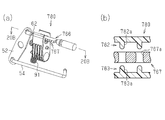
- (A) is a perspective view which shows a power transmission mechanism and a blocking mechanism for an outside handle device according to a sixth embodiment
- (b) is a cross-sectional view taken along line 20B-20B in (a).
- the outside handle device will be described with reference to FIGS.
- the front-rear direction and the width direction are defined based on the arrangement when the outside handle device is mounted on a vehicle. “Front” and “rear” of the outside handle device coincide with the front and rear of the vehicle. “Inward” in the outside handle device indicates a direction toward the inside of the vehicle in the vehicle width direction.
- the outside handle device (hereinafter referred to as “handle device 7”) is configured to operate the grip 20, the bell crank 32 (see FIG. 4), and the bell crank 32 disposed on the outer surface side of the outer panel 2 of the vehicle door 1.
- a power transmission mechanism 60 (see FIG. 2) that operates the locking device 8 based on the above and a blocking mechanism 80 (see FIG. 8) that blocks the operation of the power transmission mechanism 60 are provided.
- the handle device 7 operates the lock device 8 by operating the grip 20 so that the vehicle door 1 can be opened and closed.
- such a handle device 7 can be composed of three structures.
- the handle device 7 can be configured by three structures of the grip 20, the first unit 30 including the bell crank 32, and the second unit 50 including the blocking mechanism 80 and the power transmission mechanism 60.
- the locking device 8 is disposed behind the inner panel 3 of the vehicle door 1 (see FIG. 1).
- the lock device 8 includes a latch mechanism 10 that restrains the vehicle door 1 in a closed state, and a power control mechanism 19.
- the power control mechanism 19 controls the power transmitted to the latch mechanism 10 based on the operation of the operation unit (outside handle, inside handle, child lock operation unit) of the vehicle door 1.
- the power control mechanism 19 transmits the power from the outside handle or the inside handle to the latch mechanism 10 based on the operation of the operation unit of the vehicle door 1 or cuts off the transmission of the power, or latches by the motor.
- the mechanism 10 is operated.
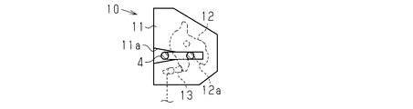
- the latch mechanism 10 includes a main body 11 having a groove 11 a, a latch 12 that engages with a striker 4 provided in the vehicle body, and a pole 13 that restricts the rotation of the latch 12.
- the latch 12 has a groove 12 a that allows the striker 4 to enter.
- the main body 11 is arranged on the inner panel 3 so that the groove 11a is exposed to the outside and the groove 11a extends along the vehicle width direction. The striker 4 attached to the entrance of the vehicle body is inserted into the groove 11a.
- the striker 4 is inserted into both the groove 11a of the main body 11 and the groove 12a of the latch 12, and the latch 12 rotates so that the extending direction of the groove 11a of the main body 11 and the extending direction of the groove 12a of the latch 12 intersect. Then, the striker 4 is restrained by the latch 12.
- the latch 12 is disposed at a position where the striker 4 is restrained (hereinafter referred to as “lock position”), the pawl 13 engages with the latch 12 and the rotation of the latch 12 is restricted. The engagement with is maintained.
- the pole 13 is moved or rotated from a position engaging with the latch 12 to a position not engaging with the latch 12 by an operation of the cable 61 described later. Therefore, when the pole 13 is operated based on the operation of the cable 61 and the engagement between the striker 4 and the latch 12 is released, the vehicle door 1 can be opened and closed.
- the above power control mechanism 19 is interposed between the pole 13 and the cable 61.
- the electrical components in the lock device 8 and the electrical components in the grip 20 are controlled by a control device provided in the vehicle body.
- a lock device connection portion 14 and a handle connection portion 15 are provided on the inner surface side (the surface side facing the vehicle interior) of the lock device 8 (see FIG. 2).
- the lock device connection portion 14 is a connection end portion of a wiring extending from an electrical component in the lock device 8.
- a first wiring 5 (including a power supply wiring and a signal wiring) extending from the control device of the vehicle main body is connected to the locking device connecting portion 14.
- the handle connection portion 15 is a vehicle main body side connection end portion of a wiring (hereinafter referred to as “handle wiring 16”) connected to an electrical component in the grip 20.
- a second wiring 6 (including a power supply wiring and a signal wiring) extending from the control device of the vehicle main body is connected to the handle connection portion 15.
- the grip 20 will be described with reference to FIGS. 4 and 5.
- the grip 20 includes a body portion 21 that is a hand-held portion, a first protrusion portion 22 that protrudes from the front end portion of the body portion 21, and a second protrusion portion 23 that protrudes from the rear end portion of the body portion 21.
- the grip 20 is provided with a cylindrical wiring guide portion 25 in the vicinity of the first protruding portion 22.
- a wiring extending from the electrical component in the grip 20 is inserted into the wiring guide portion 25.
- a connecting portion 24 (see FIG. 9) that is the end of the wiring extending from the electrical component is disposed at the tip of the cylindrical wiring guide portion 25.
- the detection sensor which detects the contact or approach of a hand is mentioned, for example.
- 1st protrusion part 22, 2nd protrusion part 23, and wiring guide part 25 protrude in the same direction.
- An engaging claw portion 23 a that engages with a bell crank 32 described later is provided at the tip of the second protruding portion 23.
- the first protrusion 22 of the grip 20 is inserted into the first through hole 31d of the base 31 of the first unit 30 together with the wiring guide 25.
- the end of the first protrusion 22 of the grip 20 is attached to the base 31 of the first unit 30 via a rotating member (not shown). With this configuration, the grip 20 rotates with respect to the base 31.
- the second protrusion 23 of the grip 20 is inserted into the second through hole 31 e of the base 31 of the first unit 30.
- the engaging claw part 23a of the 2nd protrusion part 23 of the grip 20 engages with the bell crank 32 mentioned later (refer Fig.6 (a) and FIG.6 (b)).
- the second protrusion 23 of the grip 20 moves outward (outward in the vehicle width direction) to rotate the bell crank 32.
- the position of the grip 20 when the grip 20 is not rotating the bell crank 32 is referred to as an “initial position”, and the portion near the second protrusion 23 of the grip 20 is separated from the outer panel 2.
- the position of the grip 20 when the grip 20 rotates is referred to as an “operation position”.
- the grip 20 rotates from the initial position toward the operation position the grip 20 rotates in the “operation direction”.
- the first unit 30 will be described with reference to FIGS. 5, 6 (a), and 6 (b). As shown in FIG. 5, the first unit 30 includes a base 31 attached to the inside of the outer panel 2 of the vehicle door 1 and a bell crank 32 attached to the inside of the base 31 (inside in the vehicle width direction).
- the base 31 includes a base main body 31a attached to the outer panel 2 and an edge 31b protruding from the periphery of the base main body 31a.
- a first through hole 31 d is provided on the front side of the base 31, and a second through hole 31 e is provided on the rear side of the base 31.
- the first protrusion 22 of the grip 20 is inserted through the front region of the first through hole 31d.
- the wiring guide portion 25 is inserted through the rear region of the first through hole 31d.
- a unit arrangement region 31f in which the frame 51 of the second unit 50 is arranged is provided in a portion of the base 31 between the first through hole 31d and the second through hole 31e.
- the bell crank 32 is disposed in the vicinity of the second through hole 31e.
- the bell crank 32 includes a rotating shaft 33 and a crank body 40 that is rotatably supported by the base 31 via the rotating shaft 33.
- the crank body 40 is biased by a coil spring 34 in a direction in which the grip 20 engaging with the crank body 40 is pulled inward (inward in the vehicle width direction) (FIGS. 6A and 6B). The direction of arrow B in the middle).
- the rotation shaft 33 is arranged so that the center axis thereof is parallel to the rotation axis of the grip 20.
- the crank body 40 is different from the bearing portion 41 that receives the rotation shaft 33, the first arm 42 that extends from the bearing portion 41 and engages with the engaging claw portion 23 a of the grip 20, and the bearing portion 41 to the first arm 42.
- a second arm 43 extending in the direction.
- the mass of the second arm 43 is larger than the mass of the first arm 42.
- the size (volume) of the second arm 43 is larger than that of the first arm 42.
- the second arm 43 has an outer surface 43a, a side surface 43b, an inner surface 43d, and a surface that engages with the engaging portion 54b of the flange member 54 (hereinafter referred to as an “engaging surface 43c”).
- the outer surface 43a is a surface facing the outer panel 2
- the inner surface 43d is a surface opposite to the outer surface 43a.
- the side surface 43b is a surface between the outer surface 43a and the inner surface 43d.
- the engagement surface 43c is provided between the side surface 43b and the inner surface 43d and extends inward (in the direction toward the vehicle interior).
- the engaging surface 43c may be provided on the entire boundary portion between the side surface 43b and the inner surface 43d, or may be provided on a part of the boundary portion as shown in the present embodiment (see FIG. 11).
- the engagement surface 43c faces rearward (rearward in the vehicle front-rear direction).
- the engagement surface 43c faces the outer panel 2 (that is, the base 31). That is, when the grip 20 rotates in the operation direction, the engagement surface 43c is opposite to the bell crank 32 in the engagement portion 54b of the flange member 54 (that is, the side facing the rotation axis 33 (rotation axis) of the bell crank 32). And slidably contact the engaging portion 54b.
- the second arm 43 is provided with an insertion groove 44 (see FIG. 5) through which a shaft portion 54a (see FIG. 11) of a flange member 54 described later is inserted.
- the insertion groove 44 extends so as to intersect perpendicularly to the extending direction of the engaging surface 43 c extending in the direction along the rotation shaft 33.
- the second unit 50 will be described with reference to FIGS.
- the second unit 50 includes a frame 51, a power transmission mechanism 60 that transmits the rotational power of the bell crank 32 to the lock device 8, a cover 70, and a blocking mechanism 80.
- the second unit 50 further includes a coil spring 53 that biases the lever 52.
- the frame 51 supports the components of the power transmission mechanism 60 and the blocking mechanism 80. Specifically, the frame 51 supports the end 63 a of the outer 63 of the cable 61, the flange member 54, and the lever 52, which are components of the power transmission mechanism 60, and is an inertia that is a component of the blocking mechanism 80. The member 81 is supported.
- the frame 51 rotatably supports the frame main body 51a, the first support 51b that supports the end 63a of the outer 63 of the cable 61, the second support 51c that supports the flange member 54, and the lever 52.
- a support shaft 51d and a holding portion 51e that holds the coil spring 53 are provided.
- maintenance part 51e are arrange
- the first support portion 51b and the second support portion 51c are disposed on the rear side of the frame main body portion 51a.
- the power transmission mechanism 60 includes a cable 61, a lever 52, and a flange member 54 connected to the cable 61 through the lever 52.
- the power transmission mechanism 60 includes a moving unit 66 that moves based on the rotation of the bell crank 32.
- the moving part 66 is provided in a portion of the inner cable 62 of the cable 61 that is exposed from the outer 63. That is, the moving part 66 moves together with the inner cable 62.
- the moving portion 66 is provided with an engaging portion 67 with which the first blocking portion 82 and the second blocking portion 83 of the blocking mechanism 80 are engaged.
- the engaging portion 67 protrudes from the inner cable 62.
- the engaging portion 67 is configured to include a first engaging portion 68 and a second engaging portion 69.
- the first engaging portion 68 faces in a direction perpendicular to the moving direction of the moving portion 66.
- the second engaging portion 69 is in a direction perpendicular to the moving direction of the moving portion 66 and is opposite to the first engaging portion 68.
- the first engaging portion 68 and the second engaging portion 69 protrude in opposite directions in the direction perpendicular to the moving direction of the moving portion 66.
- the engaging part 67 is constituted by a plurality of convex parts 67a.
- the convex portions 67 a are arranged at equal intervals in the extending direction of the inner cable 62.
- the convex portion 67a is formed in a ring shape or a hook shape extending in the circumferential direction of the inner cable 62, and has surfaces 67x and 67y perpendicular to the extending direction of the inner cable 62 (that is, in the moving direction of the moving portion 66).
- the first engaging portion 68 is a portion protruding outward in the vehicle width direction
- the second engaging portion 69 protrudes inward in the vehicle width direction. (See FIG. 15).
- the lever 52 is urged in a predetermined rotational direction by the coil spring 53, contacts the stopper, and stops at a predetermined position (hereinafter referred to as “first position”).
- the lever 52 rotates in a direction opposite to the predetermined rotation direction by a force against the urging force of the coil spring 53 and is disposed at a predetermined position (hereinafter, “second position”).
- the tip end portion of the inner cable 62 of the cable 61 is rotatably connected to the first end portion 52 a of the lever 52 via a connection member 65.
- An end portion of the flange member 54 (an end portion opposite to the engaging portion 54b) is rotatably connected to the second end portion 52b of the lever 52 via the connection member 55.
- the second end portion 52b is an end portion on the opposite side to the first end portion 52a across the rotation center portion of the lever 52.
- the eaves member 54 is a rod-like member and is configured by a rigid member.
- the flange member 54 includes a shaft portion 54a and an engaging portion 54b disposed at the tip of the shaft portion 54a.
- the engaging portion 54b of the flange member 54 extends perpendicular to the shaft portion 54a.
- the extending direction of the shaft portion 54 a of the flange member 54 is orthogonal to the direction along the rotation shaft 33 of the bell crank 32.
- the extending direction of the engaging portion 54 b is parallel to the direction along the rotation axis 33. With this configuration, the flange member 54 moves in the extending direction of the shaft portion 54a as the bell crank 32 rotates.
- the eaves member 54 is arranged as follows in relation to the arrangement of the bell crank 32.
- the engaging portion 54b of the flange member 54 contacts the engaging surface 43c of the bell crank 32 or is spaced from the engaging surface 43c. It arrange
- the cover 70 includes a cover main body 71 and an extension 72 extending from the cover main body 71.
- the cover main body 71 covers the lever 52, the coil spring 53, the exposed portion of the inner cable 62 of the cable 61, and a part of the shaft portion 54 a of the flange member 54.
- the frame 51 and the cover 70 constitute a case 77 (see FIG. 10) having an accommodation space for accommodating the lever 52, the coil spring 53, and the like.
- a pair of support portions 73 that rotatably support the container 74 are provided at the ends of the extension portion 72 of the cover 70.
- a connecting portion 17 of the handle wiring 16 is attached to the container 74. That is, the connection portion 17 of the handle wiring 16 is rotatably supported by the extension portion 72 of the cover 70 via the container 74.
- the above-described handle wiring 16 (wiring connected to the electrical components in the grip 20) passes through the case 77.
- the connection portion 17 of the handle wiring 16 is rotatably supported by the support portion 73 of the cover 70 as described above, and is connected to the wiring connection portion 24 extending from the electrical components in the grip 20 ( (See FIG. 9).
- the handle wiring 16 extends from the connecting portion 17 so as to pass through the case 77, and is drawn out from the case 77 and arranged along the cable 61.
- the handle wiring 16 and the cable 61 are covered together with a protective member 64 (for example, a cylindrical member such as a resin tube) (see FIG. 7).
- a through-hole 75 through which the shaft portion 54 a of the flange member 54 is inserted is provided at a boundary portion where the cover 70 and the frame 51 come into contact.
- the through hole 75 is formed by the concave second support part 51 c of the frame 51 and the concave support part 71 a of the cover 70.
- the engaging portion 54 b of the flange member 54 is disposed outside the case 77.
- the size of the through hole 75 is set so as not to limit the movement of the shaft portion 54a of the flange member 54 accompanying the rotation of the bell crank 32. Thereby, smooth rotation of the bell crank 32 is ensured. Further, the size of the through hole 75 is set so as to suppress the shaft shake of the shaft portion 54a of the flange member 54 so that the engagement between the flange member 54 and the bell crank 32 is not disengaged.
- the blocking mechanism 80 will be described with reference to FIGS.
- the prevention mechanism 80 prevents the power transmission mechanism 60 from operating when the grip 20 moves when a large inertia force is applied to the grip 20 in a collision or the like.
- the blocking mechanism 80 includes an inertia member 81 and a limiting portion 90 that limits the swing of the inertia member 81.
- the inertia member 81 has a predetermined interval between the first blocking portion 82 and the second blocking portion 83 that engage with the engaging portion 67 of the moving portion 66 of the inner cable 62, and the first blocking portion 82 and the second blocking portion 83.
- a support portion 84 that supports the opening.
- a weight 85 is accommodated in the support portion 84.
- the mass of the weight 85 is set so that the inertia member 81 is greatly shaken when a large inertia force is applied as in a collision.
- the inertia member 81 has a shaft portion 86 having a rotation axis.
- the shaft portion 86 is provided so as to protrude from each of the side surfaces of the inertia member 81.
- the shaft portion 86 is disposed at a portion between the weight 85 and the first blocking portion 82 (or the second blocking portion 83) on the side surface of the inertia member 81.
- These shaft portions 86 are rotatably supported by two bearings 56 (see FIG. 8) provided on the frame 51.
- a protrusion 87 (see FIG. 8) that protrudes in the same direction as the extending direction of the shaft portion 86 is provided on the side corresponding to the weight 85.
- the protrusion 87 engages with a coil spring 91 described later.
- the first blocking portion 82 and the second blocking portion 83 extend on the opposite side of the weight 85 with respect to the shaft portion 86. Moreover, the 1st prevention part 82 and the 2nd prevention part 83 are arrange
- the first blocking portion 82 includes an arm 82a extending from the support portion 84 and a plurality of convex portions 82b (see FIGS. 15A to 15C) protruding from the arm 82a toward the second blocking portion 83. Have.
- the convex portion 82 b has a surface 82 x perpendicular to the moving direction of the moving portion 66.
- the surface 82x can be engaged with a surface 67x of the engaging portion 67 of the moving portion 66 provided in the inner cable 62.
- the second blocking portion 83 includes an arm 83a extending from the support portion 84 and a plurality of convex portions 83b (see FIGS. 15A to 15C) protruding from the arm 83a toward the first blocking portion 82.
- the convex portion 83 b has a surface 83 x perpendicular to the moving direction of the moving portion 66.
- the surface 83x can be engaged with a surface 67x of the engaging portion 67 of the moving portion 66 provided in the inner cable 62.
- the first blocking portion 82 can engage with the first engaging portion 68 of the moving portion 66 regardless of the position of the moving portion 66 as long as the moving portion 66 of the inner cable 62 moves within a predetermined range.
- the second blocking portion 83 can engage with the second engaging portion 69 of the moving portion 66 regardless of the position of the moving portion 66 as long as the moving portion 66 of the inner cable 62 moves within a predetermined range.
- the first blocking portion 82 is composed of a plurality of convex portions 82b.
- the plurality of convex portions 82 b are arranged along the moving direction of the moving portion 66.
- the arrangement interval of the convex portions 82b is the same as the arrangement interval of the convex portions 67a of the engaging portion 67, and the gap size between the adjacent convex portions 82b can be inserted into one convex portion 67a of the engaging portion 67.
- the 2nd prevention part 83 is constituted by a plurality of convex parts 83b.
- the plurality of convex portions 83 b are arranged along the moving direction of the moving portion 66.
- the arrangement interval of the convex portions 83b is the same as the arrangement interval of the convex portions 67a of the engaging portion 67, and the gap size between the adjacent convex portions 83b can enter one convex portion 67a of the engaging portion 67. Set to dimensions.
- the restricting portion 90 is an inertia member such that the moving portion 66 is disposed between the first blocking portion 82 and the second blocking portion 83 and not in contact with the first blocking portion 82 and the second blocking portion 83. 81 is stopped. Further, when the inertia member 81 is shaken, the restricting portion 90 applies a force to the inertia member 81 in a direction opposite to the shake direction. That is, the restricting unit 90 restricts the rotation of the inertia member 81 so as to swing the inertia member 81.
- the limiting unit 90 is configured by a coil spring 91.
- a protrusion 87 of the inertia member 81 is disposed between the both end portions 91 a of the coil spring 91.
- interval of the both ends 91a and 91a of the coil spring 91 is set so that the protrusion 87 and the edge part 91a of the coil spring 91 may contact
- the operation of the blocking mechanism 80 will be described with reference to FIG.
- an impact is applied to the vehicle (especially an impact on the side of the vehicle) and an inertia force acts on the blocking mechanism 80
- the inertia member 81 swings, and one of the first blocking portion 82 or the second blocking portion 83 is moved by the moving portion 66.
- the engagement portion 67 approaches and both engage.
- an inertial force is applied to the blocking mechanism 80 when the vehicle is turning, but when the inertial force is small as described above, the swinging width of the inertia member 81 is small due to the action of the limiting portion 90, so
- the first blocking part 82 (or the second blocking part 83) and the engaging part 67 of the moving part 66 are not engaged.
- the attachment method of the handle apparatus 7 is demonstrated.
- the cover 70 is removed from the handle device 7 attached to the vehicle door 1.
- the first unit 30 is attached to the inner surface of the outer panel 2.
- the grip 20 is disposed on the outer surface of the outer panel 2, and the grip 20 is attached to the first unit 30.
- the second unit 50 is disposed at a predetermined position of the first unit 30.
- the connection portion 17 of the handle wiring 16 attached to the second unit 50 is disposed at a position facing the first through hole 31 d of the first unit 30.
- the engaging portion 54b of the flange member 54 is disposed in the bell crank 32 near the boundary between the engaging surface 43c and the inner surface 43d.
- the second unit 50 is inserted into the first unit 30.
- the frame 51 of the second unit 50 is arranged in the unit arrangement region 31f of the first unit 30, and the protrusion 31c provided on the edge 31b of the base 31 of the first unit 30 (see FIG. 4).
- the claw portion 76 provided so as to protrude from the peripheral edge of the cover 70 of the second unit 50.
- the engaging portion 54b of the flange member 54 is disposed near the boundary between the engaging surface 43c and the inner surface 43d in the bell crank 32 (see FIG. 14).
- the connection portion 17 of the handle wiring 16 is connected to a wiring connection portion 24 extending from the electrical component in the grip 20. In this way, the handle device 7 is easily attached to the vehicle door 1.
- the operation of the handle device 7 will be described.
- the operation described here is the operation of the handle device 7 when the grip 20 is operated in the closed state of the vehicle door 1.
- the grip 20 is operated and the second projecting portion 23 of the grip 20 is pulled away from the outer panel 2, the bell crank 32 rotates, and accordingly, the hook member 54 moves and the lever 52 rotates, and the cable 61
- the inner cable 62 is pulled.
- the power transmitted via the inner cable 62 is transmitted to the pole 13 of the latch mechanism 10 via the power control mechanism 19, and the pole 13 rotates.
- the pole 13 rotates, the engagement between the latch 12 and the pole 13 is released, the latch 12 can be rotated, and the engagement between the latch 12 and the striker 4 can be released. In this way, the vehicle door 1 is opened by operating the grip 20.
- FIGS. 15A to 15C are plan views of the blocking mechanism 80 and its peripheral portion as seen from the direction of arrow C shown in FIG.
- the first situation is a situation in which the next impact is applied immediately after the first impact is applied to the vehicle.
- the second situation is a situation in which an impact is applied to the vehicle, the inertia member 81 rotates in one direction due to the impact, and immediately after that, the inertia member 81 rotates in the opposite direction (the inertia member 81 bounces back).
- the first situation will be described.
- a large impact is applied to the vehicle.
- an impact acts in the vehicle width direction and an inertia force outward in the vehicle width direction is applied to the grip 20
- the same force as the operation of pulling the grip 20 from the vehicle door 1 is applied to the grip 20.
- the lock device 8 of the door 1 operates and the vehicle door 1 can be opened.
- a second impact may be continuously applied to the vehicle.
- the vehicle slips due to the first impact and crashes into an obstacle such as a wall an impact from a direction different from the initial impact is applied to the vehicle. That is, the vehicle may receive two or more impacts in a short time.
- the operation of the blocking mechanism 80 when an impact is applied twice or more will be described below.
- the moving unit 66 is positioned between the first blocking unit 82 and the second blocking unit 83 when a strong force such as an impact is not applied to the vehicle.
- a strong force such as an impact is not applied to the vehicle.
- an outward inertial force acts on the vehicle door 1 to which the impact is applied.
- the grip 20 is rotated outward, the second protrusion 23 of the grip 20 is separated from the outer panel 2, and the crank body 40 of the bell crank 32 is rotated so that the inner cable 62 is pulled.
- FIG. 15A the moving unit 66 is positioned between the first blocking unit 82 and the second blocking unit 83 when a strong force such as an impact is not applied to the vehicle.
- the inertia member 81 is shaken by the inertial force, and the first blocking portion 82 and the second blocking portion 83 move outward in the vehicle width direction.
- an inertial force such as an impact acts
- the force of the coil spring 91 and the mass of the inertial member 81 are set so that the rotational speed of the inertial member 81 is larger than the rotational speed of the grip 20. Therefore, before the rotation amount of the grip 20 increases, for example, before the rotation amount of the grip 20 becomes larger than the rotation amount corresponding to the play of the grip 20, the first blocking portion 82 of the inertia member 81 is moved to the power transmission mechanism.
- the first blocking portion 82 and the first engaging portion 68 are engaged with each other. Thereby, rotation of the grip 20 is prevented and the engagement between the latch 12 of the locking device 8 and the striker 4 of the vehicle is maintained.
- the direction of the inertial force applied to the grip 20 changes.
- an outward inertial force is applied to the grip 20, and an inertial force in a direction different from the initial impact may be applied to the inertia member 81.
- the inertial force applied to the inertia member 81 is reversed simultaneously with the inertial force applied to the grip 20 due to the second impact, the first blocking portion 82 and the first block formed by the first impact are reversed.
- the grip 20 rotates and the moving portion 66 of the power transmission mechanism 60 starts to move.
- the second blocking portion 83 approaches the second engaging portion 69 of the moving portion 66 at the same time, and FIG. ),
- the second blocking portion 83 and the second engaging portion 69 engage immediately after the moving portion 66 moves. That is, immediately after the first blocking portion 82 and the first engaging portion 68 are disengaged, the second blocking portion 83 and the second engaging portion 69 are engaged. In this way, the operation of the power transmission mechanism 60 is prevented.
- the inertia member 81 When the impact on the vehicle disappears, the inertia member 81 returns to the initial position, so that the blocking mechanism 80 and the engaging portion 67 are not engaged, and the movement of the moving portion 66 is allowed. That is, when the vehicle is stationary, the vehicle door 1 can be opened and closed.
- the blocking mechanism 80 in the second situation will be described.
- the grip 20 rotates outward as in the first situation.
- the inertia member 81 is shaken by the inertial force, and the first blocking portion 82 approaches toward the engaging portion 67 of the moving portion 66.
- the rotational speed of the inertia member 81 is excessive, the inertia member 81 is moved before the surface 82x of the convex portion 82b of the first blocking portion 82 and the surface 67x of the convex portion 67a of the engaging portion 67 are engaged. rebound.
- the second blocking portion 83 approaches toward the engaging portion 67 of the moving portion 66. Therefore, immediately after the rebounding, the second blocking portion 83 and The engaging portion 67 is engaged. Thus, even when the inertia member 81 bounces, the operation of the power transmission mechanism 60 is prevented.
- the inertia member 81 swings in the blocking mechanism 80. And the inertia member 81 is comprised so that it may engage with the engaging part 67 of the moving part 66, even if it rotates in any direction. For this reason, even when there are a plurality of continuous collisions, when the inertial force is applied, the inertia member 81 rotates in either direction, so that the blocking mechanism 80 can engage with the engaging portion 67 of the moving portion 66. .
- the blocking mechanism 80 is engaged with the moving unit 66 at the first approach (the first blocking unit 82 or the second blocking unit 83 approaches the moving unit 66). Even when not engaging with the portion 67, the blocking mechanism 80 can engage with the engaging portion 67 of the moving portion 66 because the inertia member 81 rebounds and approaches the second time. In this way, the operation of the power transmission mechanism 60 due to the collision and the opening of the vehicle door 1 are suppressed.
- the power transmission mechanism 60 includes a moving unit 66 that moves based on the operation of the bell crank 32.
- the moving part 66 is provided with an engaging part 67.
- the blocking mechanism 80 includes a first blocking unit 82 and a second blocking unit 83.
- the first blocking portion 82 engages with the engaging portion 67 of the power transmission mechanism 60 from the first direction to block the operation of the power transmission mechanism 60.
- the second blocking portion 83 engages with the engaging portion 67 of the power transmission mechanism 60 from a second direction different from the first direction to block the operation of the power transmission mechanism 60.
- the first blocking portion 82 and the second blocking portion 83 are movable and are separated from the engaging portion 67 when receiving no inertial force.
- the first direction is preferably one direction in the vehicle width direction.
- the second direction is preferably a direction opposite to the first direction.
- the moving unit 66 is configured to move in the vehicle front-rear direction.
- the first blocking unit 82 and the second blocking unit 83 are movable in a direction intersecting with the moving direction of the moving unit 66, more specifically in a direction orthogonal to the moving direction of the moving unit 66.
- the first blocking portion 82 and the second blocking portion 83 are supported so as to be swingable in the vehicle width direction.
- the swing is a movement like a pendulum that repeats positive rotation and negative rotation around a rotation axis, and a movement that repeats reciprocation along a predetermined path (for example, a straight path or a curved path). Including.
- first blocking portion 82 and the second blocking portion 83 are configured as a single body so as to swing together when receiving an inertial force.
- a fourth embodiment described later see FIG. 18). These may be configured as separate bodies as shown in FIG.
- the handle device 7 includes a case 77.
- the case 77 houses the moving part 66 of the power transmission mechanism 60 and the blocking mechanism 80.
- the engagement of the first blocking part 82 or the second blocking part 83 of the blocking mechanism 80 with the engaging part 67 of the moving part 66 is inhibited.
- the function of the blocking mechanism 80 may not be sufficiently exerted even if the inertial force acts due to impact on the vehicle or the like because the swinging of the inertia member 81 is hindered.
- the moving unit 66 is provided in the inner cable 62.
- the arrangement of the moving unit 66 is not limited to this. That is, the moving part 66 can be provided in at least one of the flange member 54, the lever 52, and the inner cable 62. That is, in this configuration, the moving part 66 and the blocking mechanism 80 that engages with the moving part 66 are arranged around the grip 20.
- the moving part 66 is provided in the inner cable 62.
- the engaging part 67 has a first engaging part 68 and a second engaging part 69.
- the first engaging portion 68 faces in a direction perpendicular to the moving direction of the moving portion 66.
- the second engaging portion 69 is a direction perpendicular to the moving direction of the moving portion 66 and faces in the opposite direction to the first engaging portion 68.
- the first blocking portion 82 and the second blocking portion 83 are disposed so as to face the first engaging portion 68 and the second engaging portion 69, respectively.
- the engagement structure between the first engagement portion 68 and the first blocking portion 82 and the engagement structure between the second engagement portion 69 and the second blocking portion 83 are configured as a meshing structure.
- at least one of the first engaging portion 68 and the first blocking portion 82 is configured by a plurality of convex portions (67a, 82b), and at least the second engaging portion 69 and the second blocking portion 83 are included.
- One side may be constituted by a plurality of convex portions (67a, 83b). According to this configuration, the first engaging portion 68 and the first blocking portion 82 are engaged, and the second engaging portion 69 and the second blocking portion 83 are engaged.
- Second Embodiment A second embodiment of the handle device 7 will be described with reference to FIG.
- the same reference numerals as those in the first embodiment are assigned to substantially the same configurations as those in the first embodiment, and different reference numerals are assigned to the different configurations. To do.
- the moving part 166 is provided on the shaft part 54a of the flange member 54.
- the structure of the engaging portion 167 is the same as that in the first embodiment.
- the structure of the blocking mechanism 180 is the same as that of the first embodiment. According to this configuration, when the inertial force is applied to the handle device 7 in the impact on the vehicle and the blocking mechanism 180 operates, the movement of the eaves member 54 is limited and the operation of the power transmission mechanism 60 is blocked.
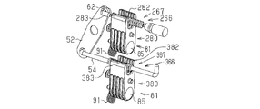
- the handle device 7 includes two moving parts (hereinafter referred to as “first moving part 266” and “second moving part 366”) and two blocking mechanisms (hereinafter referred to as “first blocking mechanism 280”, respectively). , “Second blocking mechanism 380").
- first moving part 266 and “second moving part 366”
- first blocking mechanism 280 two blocking mechanisms
- second blocking mechanism 380 blocking mechanism 380
- the inner cable 62 is provided with a first moving part 266 and a corresponding first blocking mechanism 280 is provided.
- the collar member 54 is provided with a second moving portion 366, and a second blocking mechanism 380 corresponding thereto is provided. That is, the third embodiment is a combination of the first embodiment and the second embodiment. With this configuration, the same effect as in the first embodiment and the second embodiment can be obtained.
- the mass of the weight 85 of the first blocking mechanism 280 and the second blocking mechanism 380 or the force of the coil spring 91 is set so that the vibration cycle of the first blocking mechanism 280 and the vibration cycle of the second blocking mechanism 380 are different.
- the vibration period is a period when the inertia member 81 makes a single vibration when no inertial force is applied.
- the first blocking mechanism 280 and the second blocking mechanism 380 have different rotational speeds when subjected to an impact, and their movements are not synchronized. For this reason, after the first impact, the first blocking mechanism 280 is not engaged with the engaging portion 267 of the first moving portion 266 (that is, after the first blocking portion 282 is engaged with the engaging portion 267).
- one of the first blocking portion 382 and the second blocking portion 383 of the second blocking mechanism 380 is the engaging portion of the second moving portion 366. 367 may be engaged.
- a fourth embodiment of the handle device 7 will be described with reference to FIG.
- This embodiment is a modification of the third embodiment.
- the first blocking mechanism 480 has a first blocking portion 481.
- the second blocking mechanism 580 has a second blocking portion 581.
- the first blocking portion 481 of the first blocking mechanism 480 and the second blocking portion 581 of the second blocking mechanism 580 are directed in opposite directions.
- the first blocking unit 481 corresponds to the second blocking unit 283 in the third embodiment (see FIGS. 17 and 18).
- the second blocking unit 581 corresponds to the first blocking unit 382 in the third embodiment (see FIGS. 17 and 18).
- the moving part 666 is provided on the peripheral edge of the semicircular lever 152.
- the rotation axis of the lever 152 is along the vehicle width direction.
- the moving part 666 has an engaging part 667 that engages with the blocking mechanism 680.
- the engaging portion 667 includes a first engaging portion 668 and a second engaging portion (not shown).
- the convex portion 668 a constituting the first engaging portion 668 protrudes in one direction along the rotation axis of the lever 152.
- the convex portion constituting the second engaging portion protrudes to the other side in the direction along the rotation axis of the lever 152.
- the first blocking portion and the second blocking portion of the blocking mechanism 680 are disposed so as to face the first engaging portion 668 and the second engaging portion, respectively. According to this configuration, when the inertial force is applied to the handle device 7 with the impact on the vehicle and the blocking mechanism 680 operates, the rotation of the lever 152 is limited and the operation of the power transmission mechanism 60 is blocked.
- the moving unit 766 is provided in the inner cable 62.
- the engaging portion 767 is configured as a through hole 767 a that penetrates the moving portion 766.
- the first blocking portion 782 and the second blocking portion 783 of the blocking mechanism 780 are configured as protrusions 782a and 783a configured to be inserted through the through hole 767a. Further, the first blocking portion 782 and the second blocking portion 783 are disposed so as to face the two surfaces of the moving portion 766 communicated with each other through the through hole 767a.
- the moving part 766 has two opposite surfaces on which the through hole 767a is opened, and the first blocking part 782 and the second blocking part 783 are arranged so as to face the two surfaces, respectively. According to this configuration, when the inertial force is applied to the handle device 7 due to the impact on the vehicle and the blocking mechanism 780 operates, the first blocking portion 782 or the second blocking portion 783 is engaged with the engaging portion 767. The movement of the moving unit 766 is restricted, and the operation of the power transmission mechanism 60 is prevented.
- the member provided with the moving part 766 is not limited to the inner cable 62.
- the moving part 766 may be provided on at least one of the flange member 54, the lever 52, and the inner cable 62.
- a seventh embodiment of the handle device 7 will be described with reference to FIG.
- This embodiment is a modification of the blocking mechanism in the first to sixth embodiments.
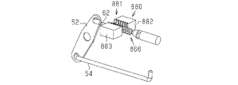
- the inertia member 881 does not rotate around the rotation axis, but reciprocates along a predetermined path.
- the inertia member 881 is supported by a guide rail (not shown) so as to be movable in a direction intersecting (specifically, orthogonal) with the moving direction of the moving unit 866.
- the inertia member 881 is supported via a spring member so that the moving portion 866 is disposed at an intermediate position between the first blocking portion 882 and the second blocking portion 883 when no inertial force is applied. Yes.
- the moving part 866 is provided in the inner cable 62.
- the moving portion 966 is provided with a through hole 967 penetrating in a direction perpendicular to the vehicle width direction and the vehicle front-rear direction, that is, the vehicle height direction, and the first engagement portion 968 and the second engagement are formed on the inner surface of the through hole 967.
- a portion 969 is provided.
- the first engaging portion 968 and the second engaging portion 969 face each other in the vehicle width direction.
- the blocking mechanism 980 includes an insertion portion 981 having a first blocking portion 982 and a second blocking portion 983.
- the insertion part 981 is disposed between the first engaging part 968 and the second engaging part 969 of the moving part 966.
- the insertion portion 981 is configured by a plurality of engagement teeth 981a protruding from the support portion 984.
- a portion of the engagement tooth 981 a that faces the first engagement portion 968 is a first blocking portion 982, and a portion that faces the second engagement portion 969 is a second blocking portion 983.
- the inner cable 62 and the flange member 54 are connected to two locations on the same side with respect to the rotation center portion. Even in such a structure, the power transmission mechanism 60 can be provided with the moving part 66, and the blocking mechanism 80 can be provided corresponding to the moving part 66.
- the engagement structure between the convex portion 67a provided in the engaging portion 67 and the convex portion 82b of the first blocking portion 82 (or the convex portion 83b of the second blocking portion 83) is It can be changed as follows. For example, as shown by a two-dot chain line in FIG. 15A, the convex portion 67a approaches the lever 52 as it goes from the root to the tip, that is, the inner cable 62 of the inner cable 62 when the grip 20 rotates outward. It can be tilted towards the direction of movement.
- the convex portion 82b of the first blocking portion 82 and the convex portion 83b of the second blocking portion 83 are separated from the lever 52 from the root toward the tip, that is, the inner cable 62 when the grip 20 rotates outward. It can be tilted in the direction opposite to the direction of movement. According to this configuration, when the convex portion 67 b of the first blocking portion 82 (or the convex portion 83 b of the second blocking portion 83) engages with the convex portion 67 a of the engaging portion 67, the inner cable between the two engaging each other. Since a pressing force in a direction perpendicular to the extending direction of 62 acts, it is difficult to disengage. As a result, the engagement time between the two becomes longer, and the rebound of the inertia member 81 such that the inertia member 81 rotates in one direction and immediately thereafter rotates in the opposite direction is suppressed.
Landscapes
- Engineering & Computer Science (AREA)
- Mechanical Engineering (AREA)
- Lock And Its Accessories (AREA)
Abstract
アウトサイドハンドル装置は、車両ドアに取り付けられるよう構成されたグリップと、グリップに係合するベルクランクと、ベルクランクの動力を車両ドアのロック装置に伝達するよう構成された動力伝達機構と、動力伝達機構の動作を阻止するよう構成された阻止機構とを備える。動力伝達機構は、ベルクランクの動作に基づいて移動する移動部を有し、移動部には係合部が設けられる。阻止機構は、第1方向から係合部に係合して動力伝達機構の動作を阻止する第1阻止部と、第1方向とは異なる第2方向から係合部に係合して動力伝達機構の動作を阻止する第2阻止部とを有する。第1阻止部及び第2阻止部は、移動可能でありかつ慣性力を受けてないとき係合部から離間する。
Description
本発明は、衝突時にグリップの回転動作を抑制する機構を備える車両ドアのアウトサイドハンドル装置に関する。
アウトサイドハンドル装置として、衝突時にグリップの回転動作を阻止する阻止機構を備えるものが知られている(例えば、特許文献1)。
特許文献1に記載の阻止機構(同文献では「慣性システム」と呼ばれている。)は、グリップ(同文献においてドアレバー)に係合し得る円筒状本体と、慣性質量体を有するアームとを備える。円筒状本体は、主回転軸線の周りで回転可能である。アームは、主回転軸線に平行な回転軸線のまわりを回転し、円筒状本体に係合し得る。
特許文献1に記載の阻止機構(同文献では「慣性システム」と呼ばれている。)は、グリップ(同文献においてドアレバー)に係合し得る円筒状本体と、慣性質量体を有するアームとを備える。円筒状本体は、主回転軸線の周りで回転可能である。アームは、主回転軸線に平行な回転軸線のまわりを回転し、円筒状本体に係合し得る。
第1の衝突時(他の車の衝突)、その衝撃によりアームの回転により円筒状本体を回転させて、円筒状本体とグリップとを係合させ、アンロック位置(車両ドアのロック装置をアンロック状態に移行させるグリップの位置)へのグリップの回転を阻止する。第1の衝突の後に連続する第2の衝突時、アームに、第1の衝撃とは反対方向の力(負の慣性の力)が作用すると、アームと円筒状本体との係合が解除され、円筒状本体は、初期位置に戻り得る状態になる。回転ダンパにより円筒状本体の復帰が緩慢になるように構成されているため、暫くの期間、円筒状本体はグリップに係合し続ける。このように、従来技術では、第1の衝突だけでなく第2の衝突においてもアウトサイドハンドルの回転が抑制される。
しかし、特許文献1に記載の技術では、第2の衝突の衝撃が大きいとき、または第2の衝突のタイミングによっては、円筒状本体が初期位置に復帰するおそれがある。円筒状本体が初期位置に復帰すると、円筒状本体とグリップの係合が解除され、車両ドアのロックを解除する方向にグリップが回転して、第2の衝撃の直後に車両ドアが開放する。すなわち、最初の衝突に起因して次の衝突が生じる状況において車両ドアが開放するおそれがある。
本発明の目的は、1回目だけでなく2回目以降の衝撃においてもグリップの回転を抑制することができるアウトサイドハンドル装置を提供することにある。
上記課題を解決するアウトサイドハンドル装置は、車両ドアに取り付けられるよう構成されたグリップと、前記グリップに係合するベルクランクと、前記ベルクランクの動力を前記車両ドアのロック装置に伝達するよう構成された動力伝達機構と、前記動力伝達機構の動作を阻止するよう構成された阻止機構とを備え、前記動力伝達機構は、前記ベルクランクの動作に基づいて移動する移動部を有し、前記移動部には係合部が設けられ、前記阻止機構は、第1方向から前記係合部に係合して前記動力伝達機構の動作を阻止する第1阻止部と、前記第1方向とは異なる第2方向から前記係合部に係合して前記動力伝達機構の動作を阻止する第2阻止部とを有し、前記第1阻止部及び前記第2阻止部は、移動可能でありかつ慣性力を受けてないとき前記係合部から離間する。
<第1実施形態>
図1~図15(c)を参照して、アウトサイドハンドル装置について説明する。
アウトサイドハンドル装置の説明では、アウトサイドハンドル装置を車両に搭載したときの配置を基準にして、前後方向及び幅方向を定義する。アウトサイドハンドル装置の「前方」及び「後方」とは、車両の前方及び後方と一致する。アウトサイドハンドル装置における「内方」とは、車幅方向において車内に向く方向を示す。
図1~図15(c)を参照して、アウトサイドハンドル装置について説明する。
アウトサイドハンドル装置の説明では、アウトサイドハンドル装置を車両に搭載したときの配置を基準にして、前後方向及び幅方向を定義する。アウトサイドハンドル装置の「前方」及び「後方」とは、車両の前方及び後方と一致する。アウトサイドハンドル装置における「内方」とは、車幅方向において車内に向く方向を示す。
アウトサイドハンドル装置(以下、「ハンドル装置7」という。)は、車両ドア1のアウタパネル2の外面側に配置されるグリップ20と、ベルクランク32(図4参照)と、ベルクランク32の動作に基づいてロック装置8を動作させる動力伝達機構60(図2参照)と、動力伝達機構60の動作を阻止する阻止機構80(図8参照)とを備える。ハンドル装置7は、グリップ20の操作によりロック装置8を動作させて、車両ドア1を開閉可能にする。
図2に示されるように、このようなハンドル装置7は、3つの構造体により構成され得る。具体的には、ハンドル装置7は、グリップ20と、ベルクランク32を含む第1ユニット30と、阻止機構80及び動力伝達機構60を含む第2ユニット50との3つの構造体により構成され得る。
ロック装置8の一例を説明する。ロック装置8は、車両ドア1のインナパネル3の後方に配置される(図1参照)。ロック装置8は、閉鎖状態にある車両ドア1を拘束するラッチ機構10と、動力制御機構19とを備える。動力制御機構19は、車両ドア1の操作部(アウトサイドハンドル、インサイドハンドル、チャイルドロック用操作部)の操作に基づいて、ラッチ機構10に伝達される動力を制御する。例えば、動力制御機構19は、車両ドア1の操作部の操作に基づいて、アウトサイドハンドルまたはインサイドハンドルからの動力をラッチ機構10に伝達したりまたは当該動力の伝達を切断したり、モータによりラッチ機構10を動作させたりする。
図3に示されるように、ラッチ機構10は、溝部11aを有する本体部11と、車体に設けられたストライカ4に係合するラッチ12と、ラッチ12の回転を規制するポール13とを備える。ラッチ12は、ストライカ4の進入を許容する溝部12aを有する。本体部11は、溝部11aが外部に露出しかつ溝部11aが車幅方向に沿って延びるようにインナパネル3に配置される。溝部11aには、車体の乗降口に取り付けられたストライカ4が挿入される。本体部11の溝部11aとラッチ12の溝部12aとの両者にストライカ4が挿入され、本体部11の溝部11aの延長方向とラッチ12の溝部12aの延長方向とが交差するようにラッチ12が回転すると、ストライカ4がラッチ12により拘束される。ラッチ12が、ストライカ4を拘束する位置(以下、「ロック位置」という。)に配置されると、ポール13がラッチ12に係合しラッチ12の回転が規制されるため、ストライカ4とラッチ12との係合が維持される。ポール13は、後述のケーブル61の動作により、ラッチ12に係合する位置から、ラッチ12に係合しない位置まで移動または回転する。従って、ケーブル61の操作に基づいてポール13が動作し、ストライカ4とラッチ12の係合が解除されると、車両ドア1の開閉が可能になる。なお、ポール13とケーブル61との間には、上述の動力制御機構19が介在する。
ロック装置8内の電装部品及びグリップ20内の電装部品(後述参照)は、車両本体に設けられる制御装置により制御される。
ロック装置8の内面側(車内に向く面側)には、ロック装置用接続部14とハンドル用接続部15とが設けられる(図2参照)。ロック装置用接続部14とは、ロック装置8内の電装部品から延びる配線の接続端部である。ロック装置用接続部14には、車両本体の制御装置から延びる第1配線5(電力供給配線及び信号配線を含む)が接続される。ハンドル用接続部15とは、グリップ20内の電装部品に接続される配線(以下、「ハンドル用配線16」という。)における車両本体側接続端部である。ハンドル用接続部15には、車両本体の制御装置から延びる第2配線6(電力供給配線及び信号配線を含む)が接続される。
ロック装置8の内面側(車内に向く面側)には、ロック装置用接続部14とハンドル用接続部15とが設けられる(図2参照)。ロック装置用接続部14とは、ロック装置8内の電装部品から延びる配線の接続端部である。ロック装置用接続部14には、車両本体の制御装置から延びる第1配線5(電力供給配線及び信号配線を含む)が接続される。ハンドル用接続部15とは、グリップ20内の電装部品に接続される配線(以下、「ハンドル用配線16」という。)における車両本体側接続端部である。ハンドル用接続部15には、車両本体の制御装置から延びる第2配線6(電力供給配線及び信号配線を含む)が接続される。
図4及び図5を参照して、グリップ20について説明する。
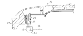
グリップ20は、手で把持される部分である胴部21と、胴部21の前端部から突出する第1突出部22と、胴部21の後端部から突出する第2突出部23とを有する。また、グリップ20には、第1突出部22の近傍に筒状の配線案内部25が設けられている。配線案内部25には、グリップ20内の電装部品から延びる配線が挿通する。電装部品から延びる配線の末端である接続部24(図9参照)は、筒状の配線案内部25の先端に配置される。なお、グリップ20内に配置される電装部品としては、例えば、手の接触または接近を検出する検出センサが挙げられる。
グリップ20は、手で把持される部分である胴部21と、胴部21の前端部から突出する第1突出部22と、胴部21の後端部から突出する第2突出部23とを有する。また、グリップ20には、第1突出部22の近傍に筒状の配線案内部25が設けられている。配線案内部25には、グリップ20内の電装部品から延びる配線が挿通する。電装部品から延びる配線の末端である接続部24(図9参照)は、筒状の配線案内部25の先端に配置される。なお、グリップ20内に配置される電装部品としては、例えば、手の接触または接近を検出する検出センサが挙げられる。
第1突出部22と第2突出部23と配線案内部25とは同じ方向に突出する。第2突出部23の先端部には、後述のベルクランク32に係合する係合爪部23aが設けられている。
グリップ20の第1突出部22は、配線案内部25と共に、第1ユニット30のベース31の第1貫通孔31dに挿通する。グリップ20の第1突出部22の端部は、回転部材(図示省略)を介して、第1ユニット30のベース31に取り付けられる。この構成により、グリップ20はベース31に対して回転する。グリップ20の第2突出部23は、第1ユニット30のベース31の第2貫通孔31eに挿通する。
グリップ20の第2突出部23の係合爪部23aは、後述のベルクランク32に係合する(図6(a)及び図6(b)参照)。グリップ20は、ベース31に対して回転すると、グリップ20の第2突出部23が外方(車幅方向における外方)に移動して、ベルクランク32を回転させる。なお、以降の説明では、グリップ20がベルクランク32を回転させていないときの、グリップ20の位置を「初期位置」といい、グリップ20の第2突出部23付近の部分がアウタパネル2から離間するようにグリップ20が回転したときの、グリップ20の位置を「操作位置」という。そして、グリップ20が初期位置から操作位置に向かって回転することを、グリップ20が「操作方向」に回転する、という。
図5、図6(a)及び図6(b)を参照して、第1ユニット30について説明する。
図5に示されるように、第1ユニット30は、車両ドア1のアウタパネル2の内側に取り付けられるベース31と、ベース31の内側(車幅方向における内側)に取り付けられるベルクランク32とを備える。
図5に示されるように、第1ユニット30は、車両ドア1のアウタパネル2の内側に取り付けられるベース31と、ベース31の内側(車幅方向における内側)に取り付けられるベルクランク32とを備える。
ベース31は、アウタパネル2に取り付けられるベース本体部31aと、ベース本体部31aの周縁から突出する縁部31bとを備える。ベース31の前側には第1貫通孔31dが設けられ、ベース31の後側には第2貫通孔31eが設けられている。第1貫通孔31dにおける前方領域には、グリップ20の第1突出部22が挿通する。第1貫通孔31dにおける後方領域には、配線案内部25が挿通する。ベース31において第1貫通孔31dと第2貫通孔31eとの間の部分には、第2ユニット50のフレーム51が配置されるユニット配置領域31fが設けられている。ベルクランク32は、第2貫通孔31eの付近に配置される。
図5に示されるように、ベルクランク32は、回転軸33と、回転軸33を介してベース31に回転可能に支持されるクランク体40とを備える。クランク体40は、クランク体40に係合するグリップ20を内方(車幅方向の内方)に引き込む方向にコイルばね34で付勢されている(図6(a)及び図6(b)中の矢印Bの方向)。回転軸33は、その中心軸線がグリップ20の回転軸線に平行となるように、配置される。
クランク体40は、回転軸33を受ける軸受部41と、軸受部41から延びてグリップ20の係合爪部23aに係合する第1アーム42と、軸受部41から第1アーム42とは異なる方向に延びる第2アーム43とを備える。第2アーム43の質量は、第1アーム42の質量に比べて大きい。具体的には、クランク体40が単一材料で構成されている場合、第2アーム43の大きさ(体積)は第1アーム42よりも大きい。
第2アーム43は、外面43aと、側面43bと、内面43dと、鉤部材54の係合部54bに係合する面(以下、「係合面43c」という。)とを有する。外面43aは、アウタパネル2に対向する面であり、内面43dは、外面43aと反対側の面である。側面43bは、外面43aと内面43dとの間の面である。係合面43cは、側面43bと内面43dとの間に設けられて内方(車内に向かう方向)に延びる。係合面43cは、側面43bと内面43dとの境界部の全部に設けられてもよいし、本実施形態に示されるように、境界部の一部分に設けられてもよい(図11参照)。
図6(a)に示されるように、グリップ20が初期位置に配置されているとき、係合面43cは、後方(車両前後方向における後方)に向く。そして、図6(b)に示されるように、グリップ20が操作方向に回転すると、係合面43cは、アウタパネル2(すなわち、ベース31)の方を向く。すなわち、グリップ20が操作方向に回転すると、係合面43cは、鉤部材54の係合部54bにおいてベルクランク32とは反対側(すなわち、ベルクランク32の回転軸33(回転軸線)に向く側とは反対側)に回り込むようにして係合部54bに摺接する。この構成によれば、ベルクランク32の回転時、鉤部材54の係合部54bにはベルクランク32の回転軸33(回転軸線)に向く力が作用し、鉤部材54の係合部54bとベルクランク32とが互いに押圧し合うようになるため、鉤部材54の係合部54bとベルクランク32の係合面43cとの係合が外れ難くなる。
また、第2アーム43には、後述の鉤部材54の軸部54a(図11参照)が挿通する挿通溝44(図5参照)が設けられている。挿通溝44は、回転軸33に沿う方向に延びる係合面43cの延長方向に対して垂直に交差するように延びる。これにより、鉤部材54は、回転軸33の中心軸線に沿う方向への移動が制限され、かつ軸部54aに沿う方向には移動が許容されるようになる。
図7~図10を参照して、第2ユニット50について説明する。
第2ユニット50は、フレーム51と、ベルクランク32の回転動力をロック装置8に伝達する動力伝達機構60と、カバー70と、阻止機構80とを備える。第2ユニット50は、更に、レバー52を付勢するコイルばね53を備える。
第2ユニット50は、フレーム51と、ベルクランク32の回転動力をロック装置8に伝達する動力伝達機構60と、カバー70と、阻止機構80とを備える。第2ユニット50は、更に、レバー52を付勢するコイルばね53を備える。
フレーム51は、動力伝達機構60の構成要素と阻止機構80とを支持する。具体的には、フレーム51は、動力伝達機構60の構成要素である、ケーブル61のアウタ63の端部63a、鉤部材54、及びレバー52を支持するとともに、阻止機構80の構成要素である慣性部材81を支持する。
フレーム51は、フレーム本体部51aと、ケーブル61のアウタ63の端部63aを支持する第1支持部51bと、鉤部材54を支持する第2支持部51cと、レバー52を回転可能に支持する支軸51dと、コイルばね53を保持する保持部51eとを有する。第1支持部51bと、第2支持部51cと、支軸51dと、保持部51eとは、フレーム本体部51aの内面(車内に向く面)に配置される。第1支持部51bと第2支持部51cとは、フレーム本体部51aにおいて後側に配置される。
動力伝達機構60は、ケーブル61と、レバー52と、レバー52を介しケーブル61に接続される鉤部材54とを備える。
動力伝達機構60は、ベルクランク32の回転に基づいて移動する移動部66を有する。本実施形態では、移動部66は、ケーブル61のインナケーブル62においてアウタ63から露出する部分に設けられている。すなわち、移動部66は、インナケーブル62と共に移動する。
動力伝達機構60は、ベルクランク32の回転に基づいて移動する移動部66を有する。本実施形態では、移動部66は、ケーブル61のインナケーブル62においてアウタ63から露出する部分に設けられている。すなわち、移動部66は、インナケーブル62と共に移動する。
移動部66には、阻止機構80の第1阻止部82及び第2阻止部83が係合する係合部67が設けられている。係合部67は、インナケーブル62から突出する。係合部67は、第1係合部68と第2係合部69とを含むように構成されている。第1係合部68は、移動部66の移動方向に垂直な方向に向く。第2係合部69は、移動部66の移動方向に垂直な方向であって第1係合部68とは反対方向に向く。言い換えば、第1係合部68及び第2係合部69は、移動部66の移動方向に垂直な方向において互いに反対方向に突出する。
例えば、係合部67は、複数の凸部67aにより構成される。凸部67aは、インナケーブル62の延長方向に等間隔で配列される。凸部67aは、インナケーブル62の周方向に延びる環形状或いは鍔形状に構成され、インナケーブル62の延長方向に(すなわち、移動部66の移動方向に)垂直な面67x,67yを有する。環状の凸部67aにより構成される係合部67において、第1係合部68は車幅方向の外方に突出する部分であり、第2係合部69は車幅方向の内方に突出する部分である(図15参照)。係合部67が阻止機構80の第1阻止部82及び第2阻止部83のいずれか一方と係合すると、移動部66にはその移動方向とは反対方向に力が加えられるため、移動部66の移動が阻止される。
レバー52は、コイルばね53により所定回転方向に付勢され、ストッパに当接して所定位置(以下、「第1位置」という。)で止まる。レバー52は、コイルばね53の付勢力に抗する力により所定回転方向とは反対方向に回転して、所定位置(以下、「第2位置」)に配置される。レバー52の第1端部52aには、ケーブル61のインナケーブル62の先端部が接続部材65を介して回転可能に接続される。レバー52の第2端部52bには、鉤部材54の端部(係合部54bとは反対側の端部)が接続部材55を介して回転可能に接続される。なお、第2端部52bは、レバー52の回転中心部を挟んで第1端部52aとは反対側にある端部である。
鉤部材54は、棒状の部材であり、剛性を有する部材により構成される。鉤部材54は、軸部54aと、軸部54aの先端に配置される係合部54bとを有する。鉤部材54の係合部54bは、軸部54aに対して垂直に延びる。鉤部材54の軸部54aの延長方向は、ベルクランク32の回転軸33に沿う方向に直交する。係合部54bの延長方向は回転軸33に沿う方向に平行である。この構成により、鉤部材54は、ベルクランク32の回転動作に伴って、軸部54aの延長方向に移動する。
また、鉤部材54は、ベルクランク32との配置関係で次のように配置される。レバー52が第1位置に配置され、かつグリップ20が初期位置にあるとき、鉤部材54の係合部54bは、ベルクランク32の係合面43cに接触するか、または係合面43cから隙間をあけて対向するところに配置される(図11参照)。
カバー70は、カバー本体部71と、カバー本体部71から延びる延長部72とを備える。カバー本体部71は、レバー52と、コイルばね53と、ケーブル61のインナケーブル62の露出部分と、鉤部材54の軸部54aの一部とを覆う。フレーム51とカバー70とは、レバー52、コイルばね53等を収容する収容空間を有するケース77(図10参照)を構成する。
カバー70の延長部72の端部には、収容体74を回転可能に支持する一対の支持部73が設けられている。収容体74には、ハンドル用配線16の接続部17が取り付けられる。すなわち、ハンドル用配線16の接続部17は、収容体74を介してカバー70の延長部72に回転可能に支持される。
上述のハンドル用配線16(グリップ20内の電装部品に接続される配線)はケース77を挿通する。ハンドル用配線16の接続部17は、ケース77の外で上述したようにカバー70の支持部73で回転可能に支持され、グリップ20内の電装部品から延びる配線の接続部24に接続される(図9参照)。ハンドル用配線16は接続部17からケース77内を通るように延びるとともに、ケース77から引き出されてケーブル61に沿うように配置される。ハンドル用配線16とケーブル61とは保護部材64(例えば、樹脂チューブ等の筒状部材)でともに覆われる(図7参照)。
図10に示されるように、カバー70とフレーム51とが接触する境界部分には、鉤部材54の軸部54aが挿通する貫通孔75が設けられている。具体的には、貫通孔75は、フレーム51の凹形状の第2支持部51cと、カバー70の凹形状の支持部71aとによって形成される。鉤部材54の係合部54bはケース77の外側に配置される。
貫通孔75の大きさは、ベルクランク32の回転に伴う鉤部材54の軸部54aの移動を制限しないように設定される。これにより、ベルクランク32の円滑な回転が確保される。また、貫通孔75の大きさは、鉤部材54とベルクランク32との係合が外れることがないように、鉤部材54の軸部54aの軸ぶれを抑えるように設定されている。
図11~図13を参照して、阻止機構80について説明する。
阻止機構80は、衝突等において大きい慣性力がグリップ20に加わることによりグリップ20が移動するとき、そのグリップ20の移動に伴って動力伝達機構60が動作することを阻止する。
阻止機構80は、衝突等において大きい慣性力がグリップ20に加わることによりグリップ20が移動するとき、そのグリップ20の移動に伴って動力伝達機構60が動作することを阻止する。
図11及び図12に示されるように、阻止機構80は、慣性部材81と、慣性部材81の揺動を制限する制限部90とを備える。
慣性部材81は、インナケーブル62の移動部66の係合部67に係合する第1阻止部82及び第2阻止部83と、第1阻止部82と前記第2阻止部83とを所定間隔をあけて支持する支持部84とを有する。
慣性部材81は、インナケーブル62の移動部66の係合部67に係合する第1阻止部82及び第2阻止部83と、第1阻止部82と前記第2阻止部83とを所定間隔をあけて支持する支持部84とを有する。
支持部84には錘85が収容されている。錘85の質量は、衝突時のように大きい慣性力が働くときに慣性部材81が大きく揺れるように設定される。
慣性部材81は、回転軸線を有する軸部86を有する。軸部86は、慣性部材81の側面それぞれから突出するように設けられている。軸部86は、慣性部材81の側面において、錘85と第1阻止部82(または第2阻止部83)との間の部分に配置される。これらの軸部86は、フレーム51に設けられた2つの軸受56(図8参照)により回転可能に支持される。慣性部材81の一方の側面において錘85と対応する側の部分には、軸部86の延長方向と同じ方向に突出する突起87(図8参照)が設けられている。突起87は、後述のコイルばね91に係合する。
慣性部材81は、回転軸線を有する軸部86を有する。軸部86は、慣性部材81の側面それぞれから突出するように設けられている。軸部86は、慣性部材81の側面において、錘85と第1阻止部82(または第2阻止部83)との間の部分に配置される。これらの軸部86は、フレーム51に設けられた2つの軸受56(図8参照)により回転可能に支持される。慣性部材81の一方の側面において錘85と対応する側の部分には、軸部86の延長方向と同じ方向に突出する突起87(図8参照)が設けられている。突起87は、後述のコイルばね91に係合する。
第1阻止部82及び第2阻止部83は、軸部86に対して錘85とは反対側に延びる。また、第1阻止部82と第2阻止部83とは、インナケーブル62の移動部66がそれらの間を通過するように間隔をあけて配置される。第1阻止部82は、支持部84から延びるアーム82aと、アーム82aから第2阻止部83に向かって突出する複数の凸部82b(図15(a)~図15(c)参照)とを有する。凸部82bは、移動部66の移動方向に垂直な面82xを有する。この面82xは、インナケーブル62に設けられた移動部66の係合部67の面67xに係合し得る。第2阻止部83は、支持部84から延びるアーム83aと、アーム83aから第1阻止部82に向かって突出する複数の凸部83b(図15(a)~図15(c)参照)とを有する。凸部83bは、移動部66の移動方向に垂直な面83xを有する。この面83xは、インナケーブル62に設けられた移動部66の係合部67の面67xに係合し得る。
第1阻止部82は、インナケーブル62の移動部66が所定範囲内で移動する限りにおいては移動部66の位置に関わらず、移動部66の第1係合部68に係合し得る。第2阻止部83は、インナケーブル62の移動部66が所定範囲内で移動する限りにおいては移動部66の位置に関わらず、移動部66の第2係合部69に係合し得る。
例えば、第1阻止部82は複数の凸部82bにより構成される。複数の凸部82bは、移動部66の移動方向に沿って配列される。凸部82bの配列間隔は、係合部67の凸部67aの配列間隔と同じであり、隣り合う凸部82b間の隙間寸法は、係合部67の1つの凸部67aが入り込むことのできる寸法に設定されている。同様に、第2阻止部83は複数の凸部83bにより構成される。複数の凸部83bは、移動部66の移動方向に沿って配列される。凸部83bの配列間隔は、係合部67の凸部67aの配列間隔と同じであり、隣り合う凸部83b間の隙間寸法は、係合部67の1つの凸部67aが入り込むことのできる寸法に設定されている。
制限部90は、第1阻止部82と第2阻止部83との間であって第1阻止部82及び第2阻止部83に接触しないところに移動部66が配置されるように、慣性部材81を静止させる。また、制限部90は、慣性部材81が揺れると、揺れた方向とは反対方向に慣性部材81に力を加える。すなわち、制限部90は、慣性部材81を揺動させるように、慣性部材81の回転を制限する。
具体的には、制限部90は、コイルばね91により構成される。コイルばね91の両端部91a,91aの間には慣性部材81の突起87が配置される。そして、慣性部材81が揺動したときに突起87とコイルばね91の端部91aとが当接するように、コイルばね91の両端部91a,91aの間隔が設定される。
図13を参照して、阻止機構80の動作を説明する。車両に衝撃(特に車両の側面への衝撃)が加わって阻止機構80に慣性力が作用すると、慣性部材81が揺動し、第1阻止部82または第2阻止部83の一方が移動部66の係合部67に接近し、両者が係合する。一方、車両が旋回走行するとき阻止機構80には慣性力が加わるが、このように慣性力が小さいときは、制限部90の作用により慣性部材81の揺動幅が小さいため、阻止機構80の第1阻止部82(または第2阻止部83)と移動部66の係合部67とは係合しない。
図14を参照して、ハンドル装置7の取り付け方法を説明する。なお、図14は、車両ドア1に取り付けたハンドル装置7からカバー70を取り外したものである。
まず、第1ユニット30をアウタパネル2の内面に取り付ける。次いで、グリップ20をアウタパネル2の外面に配置して、グリップ20を第1ユニット30に取り付ける。そして、第1ユニット30の所定位置に第2ユニット50を配置する。そうすると、第2ユニット50に取り付けられているハンドル用配線16の接続部17は、第1ユニット30の第1貫通孔31dに対向したところに配置される。また、鉤部材54の係合部54bは、ベルクランク32において係合面43cと内面43dとの境界付近に配置される。
まず、第1ユニット30をアウタパネル2の内面に取り付ける。次いで、グリップ20をアウタパネル2の外面に配置して、グリップ20を第1ユニット30に取り付ける。そして、第1ユニット30の所定位置に第2ユニット50を配置する。そうすると、第2ユニット50に取り付けられているハンドル用配線16の接続部17は、第1ユニット30の第1貫通孔31dに対向したところに配置される。また、鉤部材54の係合部54bは、ベルクランク32において係合面43cと内面43dとの境界付近に配置される。
次に、第1ユニット30に第2ユニット50を差し込む。具体的には、第1ユニット30のユニット配置領域31fに第2ユニット50のフレーム51を配置して、第1ユニット30のベース31の縁部31bに設けられている突起31c(図4参照)と、第2ユニット50のカバー70の周縁から突出するように設けられている爪部76とを係合する。そうすると、鉤部材54の係合部54bは、ベルクランク32において係合面43cと内面43dとの境界付近に配置される(図14参照)。続いて、ハンドル用配線16の接続部17を、グリップ20内の電装部品から延びる配線の接続部24に接続する。このように、ハンドル装置7は、車両ドア1に簡単に取り付けられる。
ハンドル装置7の動作を説明する。
ここで説明する動作は、車両ドア1の閉鎖状態で、グリップ20が操作されるときのハンドル装置7の動作である。グリップ20が操作されてグリップ20の第2突出部23がアウタパネル2から離れる方向に引かれると、ベルクランク32が回転し、これに伴い鉤部材54が移動してレバー52が回転し、ケーブル61のインナケーブル62が引かれる。インナケーブル62を介して伝達される動力は動力制御機構19を介してラッチ機構10のポール13に伝達され、ポール13が回転する。ポール13が回転するとラッチ12とポール13との係合が解除されて、ラッチ12の回転が可能になり、ラッチ12とストライカ4との係合が解除され得るようになる。このようにして、グリップ20の操作により車両ドア1が開放される。
ここで説明する動作は、車両ドア1の閉鎖状態で、グリップ20が操作されるときのハンドル装置7の動作である。グリップ20が操作されてグリップ20の第2突出部23がアウタパネル2から離れる方向に引かれると、ベルクランク32が回転し、これに伴い鉤部材54が移動してレバー52が回転し、ケーブル61のインナケーブル62が引かれる。インナケーブル62を介して伝達される動力は動力制御機構19を介してラッチ機構10のポール13に伝達され、ポール13が回転する。ポール13が回転するとラッチ12とポール13との係合が解除されて、ラッチ12の回転が可能になり、ラッチ12とストライカ4との係合が解除され得るようになる。このようにして、グリップ20の操作により車両ドア1が開放される。
図15(a)~図15(c)を参照して、車両に衝撃が加わるときの阻止機構80の動作を説明する。なお、図15(a)~図15(c)は、図11に示される矢印C方向からみた、阻止機構80及びその周辺部の平面図である。
ここでは、2つの状況について説明する。第1の状況は、車両に最初の衝撃が加わった直後に次の衝撃が加わるような状況である。第2の状況は、車両に衝撃が加わり、その衝撃で慣性部材81が一方向に回転しその直後に慣性部材81が逆方向に回転する状況(慣性部材81の跳ね返り状況)である。
第1の状況について説明する。
車両が壁に衝突したり、車両に他の車両が衝突したりすると、車両に大きな衝撃が加わる。特に、衝撃が車幅方向に作用し、グリップ20に車幅方向外方の慣性力が加わると、車両ドア1からグリップ20が引かれる操作と同じ力がグリップ20に加わることになるため、車両ドア1のロック装置8が動作して、車両ドア1が開放され得る。また、最初の衝突後、続けて車両に第2の衝撃が加わることがある。例えば、最初の衝撃により車両が滑って壁等の障害物に激突すると、車両には、最初の衝撃とは異なる方向からの衝撃が加わる。すなわち、車両には、短時間の間に2回以上の衝撃が加わることがある。このように2回以上の衝撃が加わるときの阻止機構80の動作を以下に説明する。
車両が壁に衝突したり、車両に他の車両が衝突したりすると、車両に大きな衝撃が加わる。特に、衝撃が車幅方向に作用し、グリップ20に車幅方向外方の慣性力が加わると、車両ドア1からグリップ20が引かれる操作と同じ力がグリップ20に加わることになるため、車両ドア1のロック装置8が動作して、車両ドア1が開放され得る。また、最初の衝突後、続けて車両に第2の衝撃が加わることがある。例えば、最初の衝撃により車両が滑って壁等の障害物に激突すると、車両には、最初の衝撃とは異なる方向からの衝撃が加わる。すなわち、車両には、短時間の間に2回以上の衝撃が加わることがある。このように2回以上の衝撃が加わるときの阻止機構80の動作を以下に説明する。
図15(a)に示されるように、車両に衝撃等の強い力が加わっていないとき、移動部66は、第1阻止部82と第2阻止部83との間に位置する。
車両の側面から内方に向かって衝撃が加わると、衝撃が加わった車両ドア1において外方への慣性力が作用する。そうすると、グリップ20が外方に回転し、グリップ20の第2突出部23がアウタパネル2から離間すると共にベルクランク32のクランク体40が回転して、インナケーブル62が引かれる。一方、図15(b)に示されるように、阻止機構80では、慣性力により慣性部材81が揺れ、第1阻止部82及び第2阻止部83は車幅方向の外方に移動する。衝撃等の慣性力が作用するとき、慣性部材81の回転速度は、グリップ20の回転速度よりも大きくなるようにコイルばね91の力及び慣性部材81の質量が設定されている。そのため、グリップ20の回転量が大きくなる前に、例えば、グリップ20の回転量がグリップ20の遊びに相当する回転量よりも大きくなる前に、慣性部材81の第1阻止部82が動力伝達機構60の移動部66に当接し、第1阻止部82と第1係合部68とが係合する。これにより、グリップ20の回転が阻止され、ロック装置8のラッチ12と車両のストライカ4との係合が維持される。
車両の側面から内方に向かって衝撃が加わると、衝撃が加わった車両ドア1において外方への慣性力が作用する。そうすると、グリップ20が外方に回転し、グリップ20の第2突出部23がアウタパネル2から離間すると共にベルクランク32のクランク体40が回転して、インナケーブル62が引かれる。一方、図15(b)に示されるように、阻止機構80では、慣性力により慣性部材81が揺れ、第1阻止部82及び第2阻止部83は車幅方向の外方に移動する。衝撃等の慣性力が作用するとき、慣性部材81の回転速度は、グリップ20の回転速度よりも大きくなるようにコイルばね91の力及び慣性部材81の質量が設定されている。そのため、グリップ20の回転量が大きくなる前に、例えば、グリップ20の回転量がグリップ20の遊びに相当する回転量よりも大きくなる前に、慣性部材81の第1阻止部82が動力伝達機構60の移動部66に当接し、第1阻止部82と第1係合部68とが係合する。これにより、グリップ20の回転が阻止され、ロック装置8のラッチ12と車両のストライカ4との係合が維持される。
最初の衝撃に続けて第2の衝撃が、最初の衝撃とは異なる方向から加わると、グリップ20に加わる慣性力の方向が変わる。このような場合、グリップ20に外方への慣性力が加わり、かつ、慣性部材81には、最初の衝撃とは異なる方向の慣性力が加わることがある。このように、第2の衝撃により、グリップ20に外方への慣性力が加わると同時に、慣性部材81に加わる慣性力が反転すると、第1の衝撃で形成された第1阻止部82と第1係合部68との係合が解除されると同時にグリップ20が回転して動力伝達機構60の移動部66が移動し出す。また、第1阻止部82と第1係合部68との係合が解除されると同時に第2阻止部83が当該移動部66の第2係合部69に接近するため、図15(c)に示されるように、移動部66の移動の直後に、第2阻止部83と第2係合部69とが係合する。すなわち、第1阻止部82と第1係合部68との係合解除の直後に第2阻止部83と第2係合部69とが係合する。このようにして、動力伝達機構60の動作が阻止される。
車両への衝撃がなくなると、慣性部材81は当初の位置に戻るため、阻止機構80と係合部67とは係合せず、移動部66の移動は許容されるようになる。すなわち、車両が静止すると、車両ドア1が開閉可能な状態になる。
第2の状況における、阻止機構80の動作を説明する。
車両の側面から内方に向かって衝撃が加わると、第1の状況と同様に、グリップ20が外方に回転する。また、阻止機構80では、慣性力により慣性部材81が揺れ、第1阻止部82が、移動部66の係合部67に向かって接近する。しかし、慣性部材81の回転速度が過大であると、第1阻止部82の凸部82bの面82xと係合部67の凸部67aの面67xとが係合する前に、慣性部材81が跳ね返る。このような慣性部材81の跳ね返りが生じると、これと同時に、第2阻止部83が、移動部66の係合部67に向かってに接近するため、跳ね返りの直後に、第2阻止部83と係合部67とが係合する。このようにして、慣性部材81の跳ね返りが生じるときでも、動力伝達機構60の動作が阻止される。
車両の側面から内方に向かって衝撃が加わると、第1の状況と同様に、グリップ20が外方に回転する。また、阻止機構80では、慣性力により慣性部材81が揺れ、第1阻止部82が、移動部66の係合部67に向かって接近する。しかし、慣性部材81の回転速度が過大であると、第1阻止部82の凸部82bの面82xと係合部67の凸部67aの面67xとが係合する前に、慣性部材81が跳ね返る。このような慣性部材81の跳ね返りが生じると、これと同時に、第2阻止部83が、移動部66の係合部67に向かってに接近するため、跳ね返りの直後に、第2阻止部83と係合部67とが係合する。このようにして、慣性部材81の跳ね返りが生じるときでも、動力伝達機構60の動作が阻止される。
ハンドル装置7の作用を説明する。
上述の阻止機構80の動作の説明で示されたように、阻止機構80では、慣性部材81が揺動する。そして、慣性部材81は、いずれの方向に回転しても、移動部66の係合部67に係合するように構成されている。このため、連続した複数の衝突があるときでも、慣性力が作用するときは慣性部材81はいずれかの方向に回転するため、阻止機構80は移動部66の係合部67に係合し得る。また、慣性部材81の回転速度が過大であることにより、最初の接近(第1阻止部82または第2阻止部83が移動部66に接近すること)では阻止機構80が移動部66の係合部67に係合しない場合でも、慣性部材81の跳ね返りにより2回目の接近があるため、阻止機構80は移動部66の係合部67に係合し得る。このようにして、衝突に起因して動力伝達機構60の動作し車両ドア1が開放されることが抑制される。
上述の阻止機構80の動作の説明で示されたように、阻止機構80では、慣性部材81が揺動する。そして、慣性部材81は、いずれの方向に回転しても、移動部66の係合部67に係合するように構成されている。このため、連続した複数の衝突があるときでも、慣性力が作用するときは慣性部材81はいずれかの方向に回転するため、阻止機構80は移動部66の係合部67に係合し得る。また、慣性部材81の回転速度が過大であることにより、最初の接近(第1阻止部82または第2阻止部83が移動部66に接近すること)では阻止機構80が移動部66の係合部67に係合しない場合でも、慣性部材81の跳ね返りにより2回目の接近があるため、阻止機構80は移動部66の係合部67に係合し得る。このようにして、衝突に起因して動力伝達機構60の動作し車両ドア1が開放されることが抑制される。
以下、ハンドル装置7の効果を説明する。
(1)実施形態では、動力伝達機構60は、ベルクランク32の動作に基づいて移動する移動部66を有する。移動部66には係合部67が設けられる。阻止機構80は、第1阻止部82と第2阻止部83とを備える。第1阻止部82は、第1方向から動力伝達機構60の係合部67に係合して動力伝達機構60の動作を阻止する。第2阻止部83は、第1方向とは異なる第2方向から動力伝達機構60の係合部67に係合して動力伝達機構60の動作を阻止する。第1阻止部82及び第2阻止部83は、移動可能でありかつ慣性力を受けてないとき係合部67から離間する。第1方向とは、好ましくは車幅方向における一方の方向である。第2方向とは、好ましくは第1方向と反対方向である。移動部66は車両前後方向に移動するように構成されている。第1阻止部82及び第2阻止部83は移動部66の移動方向と交差する方向、より具体的には移動部66の移動方向と直交する方向に移動可能である。また、好ましくは、第1阻止部82及び第2阻止部83は、車幅方向に揺動可能に支持される。ここで、揺動とは、回転軸線を中心に正回転と負回転とを繰り返す振り子のような運動と、所定経路(例えば、直線経路または湾曲した経路)に沿って往復運動を繰り返す運動とを含む。
(1)実施形態では、動力伝達機構60は、ベルクランク32の動作に基づいて移動する移動部66を有する。移動部66には係合部67が設けられる。阻止機構80は、第1阻止部82と第2阻止部83とを備える。第1阻止部82は、第1方向から動力伝達機構60の係合部67に係合して動力伝達機構60の動作を阻止する。第2阻止部83は、第1方向とは異なる第2方向から動力伝達機構60の係合部67に係合して動力伝達機構60の動作を阻止する。第1阻止部82及び第2阻止部83は、移動可能でありかつ慣性力を受けてないとき係合部67から離間する。第1方向とは、好ましくは車幅方向における一方の方向である。第2方向とは、好ましくは第1方向と反対方向である。移動部66は車両前後方向に移動するように構成されている。第1阻止部82及び第2阻止部83は移動部66の移動方向と交差する方向、より具体的には移動部66の移動方向と直交する方向に移動可能である。また、好ましくは、第1阻止部82及び第2阻止部83は、車幅方向に揺動可能に支持される。ここで、揺動とは、回転軸線を中心に正回転と負回転とを繰り返す振り子のような運動と、所定経路(例えば、直線経路または湾曲した経路)に沿って往復運動を繰り返す運動とを含む。
この構成によれば、車両への衝撃により、ハンドル装置7に慣性力が作用するとき、動力伝達機構60における移動部66の係合部67に第1阻止部82及び第2阻止部83の一方が当接して係合するため、移動部66の移動が止められて動力伝達機構60の動作が阻止される。更に、最初の衝撃の後の第2の衝撃に基づいて最初とは異なる方向への慣性力がハンドル装置7に加えられるとき、係合部67に対する第1阻止部82及び第2阻止部83の一方の係合が解除される一方で、係合部67に第1阻止部82及び第2阻止部83の他方が係合するようになる。このため、第2の衝撃においても移動部66の移動が止められて動力伝達機構60の動作が阻止される。このようにして、1回目だけでなく2回目以降の衝撃においても動力伝達機構60の動作が阻止され、グリップ20の回転が抑制される。
なお、第1阻止部82及び第2阻止部83は、本実施形態では、慣性力を受けるとき一体で揺動するように一体物として構成されるが、後述の第4実施形態(図18参照)に示されるようにこれらは別体としても構成され得る。
(2)実施形態において、ハンドル装置7はケース77を備える。ケース77は、動力伝達機構60の移動部66と、阻止機構80とを収容する。移動部66及び阻止機構80に埃等が溜まったりまたは水が付着したりすると、移動部66の係合部67に対する阻止機構80の第1阻止部82または第2阻止部83の係合が阻害されたり、慣性部材81の揺動が阻害されたりして、車両への衝撃等で慣性力が作用しても阻止機構80の機能が十分に発揮されないようになる虞がある。この点、上記構成によれば、移動部66及び阻止機構80に埃、塵または水等の異物が付着することが抑制されるため、慣性力が作用しても阻止機構80の機能が十分に発揮されないといった事態の発生が抑制される。
(3)実施形態において、移動部66は、インナケーブル62に設けられている。なお、移動部66の配置はこれに限定されない。すなわち、移動部66は、鉤部材54、レバー52、及びインナケーブル62のうちの少なくとも1つに設けられ得る。すなわち、この構成では、移動部66及びこの移動部66に係合する阻止機構80はグリップ20の周辺に配置される。
(4)実施形態において、移動部66はインナケーブル62に設けられている。係合部67は、第1係合部68と第2係合部69とを有する。第1係合部68は、移動部66の移動方向に垂直な方向に向く。第2係合部69は、移動部66の移動方向に垂直な方向であって、第1係合部68とは反対方向に向く。第1阻止部82及び第2阻止部83は、第1係合部68及び第2係合部69にそれぞれ向かいあうように配置されている。この構成によれば、車両への衝撃においてハンドル装置7に慣性力が加わり阻止機構80が動作するとき、インナケーブル62の移動が制限されて動力伝達機構60の動作が阻止される。
(5)実施形態において、第1係合部68と第1阻止部82との係合構造及び第2係合部69と第2阻止部83との係合構造は噛合構造として構成される。具体的には、第1係合部68及び第1阻止部82の少なくとも一方が、複数の凸部(67a,82b)により構成され、かつ第2係合部69及び第2阻止部83の少なくとも一方が、複数の凸部(67a,83b)により構成され得る。この構成によれば、第1係合部68と第1阻止部82とが係合し、また第2係合部69と第2阻止部83とが係合する。
<第2実施形態>
図16を参照して、ハンドル装置7の第2実施形態を説明する。なお、第2実施形態及びこれ以降の実施形態の説明では、第1実施形態と実質的に同じ構成については同実施形態と同じ符号を付し、異なる構成には別の符号を付して説明する。
図16を参照して、ハンドル装置7の第2実施形態を説明する。なお、第2実施形態及びこれ以降の実施形態の説明では、第1実施形態と実質的に同じ構成については同実施形態と同じ符号を付し、異なる構成には別の符号を付して説明する。
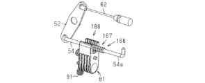
本実施形態では、移動部166は鉤部材54の軸部54aに設けられている。係合部167の構造は第1実施形態と同じである。また、阻止機構180の構造も第1実施形態と同じである。この構成によれば、車両への衝撃においてハンドル装置7に慣性力が加わり阻止機構180が動作するとき、鉤部材54の移動が制限されて動力伝達機構60の動作が阻止される。
<第3実施形態>
図17を参照して、ハンドル装置7の第3実施形態を説明する。ハンドル装置7は、2つの移動部(以下、それぞれを「第1移動部266」、「第2移動部366」という。)と、2つの阻止機構(以下、それぞれを「第1阻止機構280」、「第2阻止機構380」という。)とを備える。具体的には、第1実施形態と同様に、インナケーブル62に第1移動部266が設けられてこれに対応する第1阻止機構280が設けられる。また、第2実施形態と同様に、鉤部材54に第2移動部366が設けられてこれに対応する第2阻止機構380が設けられる。すなわち、第3実施形態は第1実施形態と第2実施形態とを組み合わせたものである。この構成によっても、第1実施形態及び第2実施形態と同様の効果が得られる。
図17を参照して、ハンドル装置7の第3実施形態を説明する。ハンドル装置7は、2つの移動部(以下、それぞれを「第1移動部266」、「第2移動部366」という。)と、2つの阻止機構(以下、それぞれを「第1阻止機構280」、「第2阻止機構380」という。)とを備える。具体的には、第1実施形態と同様に、インナケーブル62に第1移動部266が設けられてこれに対応する第1阻止機構280が設けられる。また、第2実施形態と同様に、鉤部材54に第2移動部366が設けられてこれに対応する第2阻止機構380が設けられる。すなわち、第3実施形態は第1実施形態と第2実施形態とを組み合わせたものである。この構成によっても、第1実施形態及び第2実施形態と同様の効果が得られる。
この構成において、第1阻止機構280の振動周期と第2阻止機構380の振動周期とが異なるように、第1阻止機構280及び第2阻止機構380の錘85の質量またはコイルばね91の力を調整してもよい。ここで振動周期とは、慣性力が作用していないとき慣性部材81が単振動するときの周期である。この構成によれば、第1阻止機構280と第2阻止機構380とは、衝撃を受けたときの回転速度が異なるようになり、両者の動きは同期しない。このため、最初の衝撃後、第1阻止機構280が第1移動部266の係合部267に係合していない期間(すなわち、第1阻止部282が係合部267に係合してから、第2阻止部283が係合部267に係合するまでの期間)に、第2阻止機構380の第1阻止部382及び第2阻止部383の一方が第2移動部366の係合部367に係合し得る。これにより、第1の衝撃に次ぐ第2の衝撃が加わるとき、第2の衝撃後から動力伝達機構60の動作が阻止されるまでの時間が短縮され得る。
<第4実施形態>
図18を参照して、ハンドル装置7の第4実施形態を説明する。本実施形態は、第3実施形態の変形例である。第1阻止機構480は第1阻止部481を有する。第2阻止機構580は第2阻止部581を有する。第1阻止機構480の第1阻止部481と第2阻止機構580の第2阻止部581とは互いに反対方向に向く。なお、本実施形態では、第1阻止部481は、第3実施形態における第2阻止部283に対応する(図17及び図18参照)。また、第2阻止部581は、第3実施形態における第1阻止部382に対応する(図17及び図18参照)。この構成では、第3実施形態に準じた効果が得られる。
図18を参照して、ハンドル装置7の第4実施形態を説明する。本実施形態は、第3実施形態の変形例である。第1阻止機構480は第1阻止部481を有する。第2阻止機構580は第2阻止部581を有する。第1阻止機構480の第1阻止部481と第2阻止機構580の第2阻止部581とは互いに反対方向に向く。なお、本実施形態では、第1阻止部481は、第3実施形態における第2阻止部283に対応する(図17及び図18参照)。また、第2阻止部581は、第3実施形態における第1阻止部382に対応する(図17及び図18参照)。この構成では、第3実施形態に準じた効果が得られる。
<第5実施形態>
図19を参照して、ハンドル装置7の第5実施形態を説明する。本実施形態では、移動部666は、半円形状のレバー152の周縁部に設けられている。レバー152の回転軸線は車幅方向に沿う。移動部666は、阻止機構680に係合する係合部667を有する。
図19を参照して、ハンドル装置7の第5実施形態を説明する。本実施形態では、移動部666は、半円形状のレバー152の周縁部に設けられている。レバー152の回転軸線は車幅方向に沿う。移動部666は、阻止機構680に係合する係合部667を有する。
係合部667は、第1係合部668と第2係合部(図示省略)とを含む。第1係合部668を構成する凸部668aは、レバー152の回転軸線に沿う方向で一方に突出する。第2係合部を構成する凸部は、レバー152の回転軸線に沿う方向で他方に突出する。阻止機構680の第1阻止部及び第2阻止部は、第1係合部668及び第2係合部にそれぞれ向かいあうように配置されている。この構成によれば、車両への衝撃に伴いハンドル装置7に慣性力が加わり阻止機構680が動作するとき、レバー152の回転が制限されて動力伝達機構60の動作が阻止される。
<第6実施形態>
図20(a)及び図20(b)を参照して、ハンドル装置7の第6実施形態を説明する。本実施形態では、移動部766はインナケーブル62に設けられる。係合部767は、移動部766を貫通する貫通孔767aとして構成される。阻止機構780の第1阻止部782及び第2阻止部783は、貫通孔767aに挿通するように構成された突起部782a,783aとして構成されている。また、第1阻止部782及び第2阻止部783は、貫通孔767aで連通される移動部766の2つの面にそれぞれ向かいあうように配置されている。すなわち、移動部766は、貫通孔767aが開口する互いに反対側の2つの面を有し、第1阻止部782及び第2阻止部783はこれら2つの面にそれぞれ向かいあうように配置されている。この構成によれば、車両への衝撃に伴いハンドル装置7に慣性力が加わり阻止機構780が動作するとき、係合部767に第1阻止部782または第2阻止部783が係合することにより、移動部766の移動が制限されて、動力伝達機構60の動作が阻止される。なお、この構成において、移動部766が設けられる部材はインナケーブル62に限定されない。移動部766は鉤部材54、レバー52及びインナケーブル62のうちの少なくとも1つに設けられ得る。
図20(a)及び図20(b)を参照して、ハンドル装置7の第6実施形態を説明する。本実施形態では、移動部766はインナケーブル62に設けられる。係合部767は、移動部766を貫通する貫通孔767aとして構成される。阻止機構780の第1阻止部782及び第2阻止部783は、貫通孔767aに挿通するように構成された突起部782a,783aとして構成されている。また、第1阻止部782及び第2阻止部783は、貫通孔767aで連通される移動部766の2つの面にそれぞれ向かいあうように配置されている。すなわち、移動部766は、貫通孔767aが開口する互いに反対側の2つの面を有し、第1阻止部782及び第2阻止部783はこれら2つの面にそれぞれ向かいあうように配置されている。この構成によれば、車両への衝撃に伴いハンドル装置7に慣性力が加わり阻止機構780が動作するとき、係合部767に第1阻止部782または第2阻止部783が係合することにより、移動部766の移動が制限されて、動力伝達機構60の動作が阻止される。なお、この構成において、移動部766が設けられる部材はインナケーブル62に限定されない。移動部766は鉤部材54、レバー52及びインナケーブル62のうちの少なくとも1つに設けられ得る。
<第7実施形態>
図21を参照して、ハンドル装置7の第7実施形態を説明する。本実施形態は、第1~第6実施形態における阻止機構の変形例である。本実施形態の阻止機構880では、慣性部材881は、回転軸線を中心に回転するものではなく、所定経路を往復する。具体的には、慣性部材881は、ガイドレール(図示省略)で移動部866の移動方向と交差(具体的には直交)する方向へ移動可能に支持される。また、慣性部材881は、慣性力が加わっていないときに、第1阻止部882と第2阻止部883との中間位置に移動部866が配置されるように、ばね部材を介して支持されている。すなわち、第1阻止部882及び第2阻止部883の一方が移動部866に接近するとき他方が離間するように構成され、かつ第1阻止部882及び第2阻止部883は移動部866を中心として往復運動するように構成されている。このため、第1~第6実施形態と同様の効果が得られる。
図21を参照して、ハンドル装置7の第7実施形態を説明する。本実施形態は、第1~第6実施形態における阻止機構の変形例である。本実施形態の阻止機構880では、慣性部材881は、回転軸線を中心に回転するものではなく、所定経路を往復する。具体的には、慣性部材881は、ガイドレール(図示省略)で移動部866の移動方向と交差(具体的には直交)する方向へ移動可能に支持される。また、慣性部材881は、慣性力が加わっていないときに、第1阻止部882と第2阻止部883との中間位置に移動部866が配置されるように、ばね部材を介して支持されている。すなわち、第1阻止部882及び第2阻止部883の一方が移動部866に接近するとき他方が離間するように構成され、かつ第1阻止部882及び第2阻止部883は移動部866を中心として往復運動するように構成されている。このため、第1~第6実施形態と同様の効果が得られる。
<第8実施形態>
図22を参照して、ハンドル装置7の第8実施形態を説明する。本実施形態は、第1実施形態における阻止機構の変形例である。本実施形態では、移動部866はインナケーブル62に設けられる。移動部966には、車幅方向及び車両前後方向に垂直な方向、すなわち車両高さ方向、に貫く貫通孔967が設けられ、貫通孔967の内面に第1係合部968と第2係合部969とが設けられている。第1係合部968と第2係合部969とは車幅方向に対向する。阻止機構980は、第1阻止部982と第2阻止部983とを有する挿通部981を備える。挿通部981は、移動部966の第1係合部968と第2係合部969との間に配置される。挿通部981は、支持部984から突出する複数の係合歯981aにより構成される。係合歯981aにおいて第1係合部968に対向する部分が第1阻止部982であり、第2係合部969に対向する部分が第2阻止部983である。この構成によれば、車両への衝撃によりハンドル装置7に慣性力が作用するとき、阻止機構980の揺動により挿通部981が移動部966の第1係合部968または第2係合部969に係合する。このため、本実施形態に係るハンドル装置7は、第1実施形態に準じた効果を奏する。
図22を参照して、ハンドル装置7の第8実施形態を説明する。本実施形態は、第1実施形態における阻止機構の変形例である。本実施形態では、移動部866はインナケーブル62に設けられる。移動部966には、車幅方向及び車両前後方向に垂直な方向、すなわち車両高さ方向、に貫く貫通孔967が設けられ、貫通孔967の内面に第1係合部968と第2係合部969とが設けられている。第1係合部968と第2係合部969とは車幅方向に対向する。阻止機構980は、第1阻止部982と第2阻止部983とを有する挿通部981を備える。挿通部981は、移動部966の第1係合部968と第2係合部969との間に配置される。挿通部981は、支持部984から突出する複数の係合歯981aにより構成される。係合歯981aにおいて第1係合部968に対向する部分が第1阻止部982であり、第2係合部969に対向する部分が第2阻止部983である。この構成によれば、車両への衝撃によりハンドル装置7に慣性力が作用するとき、阻止機構980の揺動により挿通部981が移動部966の第1係合部968または第2係合部969に係合する。このため、本実施形態に係るハンドル装置7は、第1実施形態に準じた効果を奏する。
<その他の実施形態>
・図23を参照して、ハンドル装置7について、他の実施形態を説明する。
第1実施形態では、グリップ20が操作されるとき、ケーブル61のインナケーブル62の移動方向と鉤部材54の移動方向とが逆である。これに対して図23に示されるハンドル装置107では、ケーブル61のインナケーブル62の移動方向と鉤部材54の移動方向とが同じ方向である。具体的には、前者の実施形態では、レバー52において回転中心部を間に挟む2箇所にそれぞれインナケーブル62と鉤部材54とが接続されているが、後者のすなわち図23の実施形態では、レバー152において回転中心部に対して同じ側の2箇所にインナケーブル62と鉤部材54とが接続される。このような構造においても、動力伝達機構60に移動部66を設け、この移動部66に対応して阻止機構80を設けることができる。
・図23を参照して、ハンドル装置7について、他の実施形態を説明する。
第1実施形態では、グリップ20が操作されるとき、ケーブル61のインナケーブル62の移動方向と鉤部材54の移動方向とが逆である。これに対して図23に示されるハンドル装置107では、ケーブル61のインナケーブル62の移動方向と鉤部材54の移動方向とが同じ方向である。具体的には、前者の実施形態では、レバー52において回転中心部を間に挟む2箇所にそれぞれインナケーブル62と鉤部材54とが接続されているが、後者のすなわち図23の実施形態では、レバー152において回転中心部に対して同じ側の2箇所にインナケーブル62と鉤部材54とが接続される。このような構造においても、動力伝達機構60に移動部66を設け、この移動部66に対応して阻止機構80を設けることができる。
・第1実施形態に係るハンドル装置7において、係合部67に設けられる凸部67aと第1阻止部82の凸部82b(または第2阻止部83の凸部83b)との係合構造は次のように変更され得る。例えば、図15(a)の2点鎖線で示すように、凸部67aは、根元から先端に行くに従ってレバー52に近づくように、すなわち、グリップ20が外方に回転するときのインナケーブル62の移動方向に向かって、傾けられ得る。第1阻止部82の凸部82b及び第2阻止部83の凸部83bは、根元から先端に行くに従ってレバー52から離れるように、すなわち、グリップ20が外方に回転するときのインナケーブル62の移動方向とは反対方向に向かって、傾けられ得る。この構成によれば、係合部67の凸部67aに第1阻止部82の凸部82b(または第2阻止部83の凸部83b)が係合すると、互いに係合する両者間でインナケーブル62の延長方向とは垂直方向における押圧力が作用するようになるため、その係合が外れ難くなる。これにより、両者の係合時間が長くなり、慣性部材81が一方向に回転しその直後にその逆の方向に回転するといった慣性部材81の跳ね返りが抑制される。
Claims (9)
- 車両ドアに取り付けられるよう構成されたグリップと、
前記グリップに係合するベルクランクと、
前記ベルクランクの動力を前記車両ドアのロック装置に伝達するよう構成された動力伝達機構と、
前記動力伝達機構の動作を阻止するよう構成された阻止機構と、を備え、
前記動力伝達機構は、前記ベルクランクの動作に基づいて移動する移動部を有し、前記移動部には係合部が設けられ、
前記阻止機構は、第1方向から前記係合部に係合して前記動力伝達機構の動作を阻止する第1阻止部と、前記第1方向とは異なる第2方向から前記係合部に係合して前記動力伝達機構の動作を阻止する第2阻止部とを有し、前記第1阻止部及び前記第2阻止部は、移動可能でありかつ慣性力を受けてないとき前記係合部から離間する、アウトサイドハンドル装置。 - 前記移動部と前記阻止機構とを収容するケースを更に備える
請求項1に記載のアウトサイドハンドル装置。 - 前記動力伝達機構は、前記ベルクランクに係合する鉤部材と、前記鉤部材に係合するレバーと、インナケーブルを有するケーブルとを備え、前記インナケーブルは、前記レバーに接続される一端部と前記ロック装置に接続される他端部とを有し、
前記移動部は、前記鉤部材、前記レバー、及び前記インナケーブルのうちの少なくとも1つに設けられている
請求項1または請求項2に記載のアウトサイドハンドル装置。 - 前記移動部は前記インナケーブルに設けられ、
前記係合部は、前記移動部の移動方向に垂直な方向に向く第1係合部と、前記移動部の移動方向に垂直な方向であって前記第1係合部とは反対方向に向く第2係合部とを含み、
前記第1阻止部及び前記第2阻止部は、前記第1係合部及び前記第2係合部にそれぞれ向かいあうように配置されている
請求項3に記載のアウトサイドハンドル装置。 - 前記鉤部材は前記移動部を有する軸部を備え、
前記係合部は、前記移動部の移動方向に垂直な方向に向く第1係合部と、前記移動部の移動方向に垂直な方向であって前記第1係合部とは反対方向に向く第2係合部とを含み、
前記第1阻止部及び前記第2阻止部は、前記第1係合部及び前記第2係合部にそれぞれ向かいあうように配置されている
請求項3に記載のアウトサイドハンドル装置。 - 前記移動部は第1移動部と第2移動部とを含み、
前記第1移動部は前記インナケーブルに設けられ、前記鉤部材は前記第2移動部を有する軸部を備え、
前記係合部は、前記第1移動部に設けられて前記第1移動部の移動方向に垂直な方向に向く第1係合部と、前記第2移動部に設けられて前記第2移動部の移動方向に垂直な方向であって前記第1係合部とは反対方向に向く第2係合部とを含み、
前記阻止機構は、前記第1移動部に対応する第1阻止機構と、前記第2移動部に対応する第2阻止機構とを含む
請求項3に記載のアウトサイドハンドル装置。 - 前記移動部は前記レバーの周縁部に設けられ、
前記係合部は、前記移動部の移動方向に垂直な方向に向く第1係合部と、前記移動部の移動方向に垂直な方向であって前記第1係合部とは反対方向に向く第2係合部とを含み、
前記第1阻止部及び前記第2阻止部は、前記第1係合部及び前記第2係合部にそれぞれ向かいあうように配置されている
請求項3に記載のアウトサイドハンドル装置。 - 前記第1係合部及び前記第1阻止部の少なくとも一方は複数の凸部であり、前記第2係合部及び前記第2阻止部の少なくとも一方は複数の凸部である
請求項4~請求項7のいずれか一項に記載のアウトサイドハンドル装置。 - 前記係合部は、前記移動部を貫通する貫通孔であり、
前記第1阻止部及び前記第2阻止部は、前記貫通孔に挿通するように構成された突起部であり、前記貫通孔で連通される前記移動部の2つの面にそれぞれ向かいあうように配置されている
請求項3に記載のアウトサイドハンドル装置。
Applications Claiming Priority (2)
| Application Number | Priority Date | Filing Date | Title |
|---|---|---|---|
| JP2016016433A JP2017133318A (ja) | 2016-01-29 | 2016-01-29 | アウトサイドハンドル装置 |
| JP2016-016433 | 2016-01-29 |
Publications (1)
| Publication Number | Publication Date |
|---|---|
| WO2017130606A1 true WO2017130606A1 (ja) | 2017-08-03 |
Family
ID=59398107
Family Applications (1)
| Application Number | Title | Priority Date | Filing Date |
|---|---|---|---|
| PCT/JP2016/087845 Ceased WO2017130606A1 (ja) | 2016-01-29 | 2016-12-19 | アウトサイドハンドル装置 |
Country Status (2)
| Country | Link |
|---|---|
| JP (1) | JP2017133318A (ja) |
| WO (1) | WO2017130606A1 (ja) |
Cited By (5)
| Publication number | Priority date | Publication date | Assignee | Title |
|---|---|---|---|---|
| JP2020097848A (ja) * | 2018-12-18 | 2020-06-25 | 三井金属アクト株式会社 | 自動車用ドアラッチ装置 |
| US11248400B2 (en) * | 2017-09-25 | 2022-02-15 | Volkswagen Aktiengesellschaft | Door handle device for a door of a motor vehicle, door, and motor vehicle |
| US11866963B2 (en) | 2020-07-09 | 2024-01-09 | D. la Porte Söhne GmbH | Remotely actuable release device for a vehicle door lock |
| US20250034913A1 (en) * | 2021-12-15 | 2025-01-30 | Minebea Accesssolutions Italia S.P.A. | Inertial safety system for a vehicle door handle |
| US20250270857A1 (en) * | 2024-02-23 | 2025-08-28 | Witte Automotive Gmbh | Door handle |
Citations (3)
| Publication number | Priority date | Publication date | Assignee | Title |
|---|---|---|---|---|
| JP2014040711A (ja) * | 2012-08-21 | 2014-03-06 | Toyota Motor Corp | 車両側部構造 |
| JP5471921B2 (ja) * | 2010-07-15 | 2014-04-16 | スズキ株式会社 | 車両用ドアハンドルのストッパ構造 |
| JP2015004221A (ja) * | 2013-06-21 | 2015-01-08 | アイシン精機株式会社 | 車両用ドアハンドル装置 |
-
2016
- 2016-01-29 JP JP2016016433A patent/JP2017133318A/ja active Pending
- 2016-12-19 WO PCT/JP2016/087845 patent/WO2017130606A1/ja not_active Ceased
Patent Citations (3)
| Publication number | Priority date | Publication date | Assignee | Title |
|---|---|---|---|---|
| JP5471921B2 (ja) * | 2010-07-15 | 2014-04-16 | スズキ株式会社 | 車両用ドアハンドルのストッパ構造 |
| JP2014040711A (ja) * | 2012-08-21 | 2014-03-06 | Toyota Motor Corp | 車両側部構造 |
| JP2015004221A (ja) * | 2013-06-21 | 2015-01-08 | アイシン精機株式会社 | 車両用ドアハンドル装置 |
Cited By (5)
| Publication number | Priority date | Publication date | Assignee | Title |
|---|---|---|---|---|
| US11248400B2 (en) * | 2017-09-25 | 2022-02-15 | Volkswagen Aktiengesellschaft | Door handle device for a door of a motor vehicle, door, and motor vehicle |
| JP2020097848A (ja) * | 2018-12-18 | 2020-06-25 | 三井金属アクト株式会社 | 自動車用ドアラッチ装置 |
| US11866963B2 (en) | 2020-07-09 | 2024-01-09 | D. la Porte Söhne GmbH | Remotely actuable release device for a vehicle door lock |
| US20250034913A1 (en) * | 2021-12-15 | 2025-01-30 | Minebea Accesssolutions Italia S.P.A. | Inertial safety system for a vehicle door handle |
| US20250270857A1 (en) * | 2024-02-23 | 2025-08-28 | Witte Automotive Gmbh | Door handle |
Also Published As
| Publication number | Publication date |
|---|---|
| JP2017133318A (ja) | 2017-08-03 |
Similar Documents
| Publication | Publication Date | Title |
|---|---|---|
| JP2017133318A (ja) | アウトサイドハンドル装置 | |
| US9856675B2 (en) | Safety device for vehicle door handle | |
| JP5663714B2 (ja) | 自動車両のドア開閉体のハンドル | |
| JP6061092B2 (ja) | 車両用ドアハンドル装置 | |
| KR101457717B1 (ko) | 안전 장치를 구비한 차량용 손잡이 | |
| US12123226B2 (en) | Door latch device | |
| US9605450B2 (en) | Vehicle door closure system including speed-based latch release | |
| US9637954B2 (en) | Vehicle door outer handle structure | |
| ITMI20111130A1 (it) | Dispositivo di sicurezza per una maniglia di portiera di veicolo. | |
| KR101470248B1 (ko) | 차량 측면 충돌 시 도어 열림 방지장치 | |
| KR101755828B1 (ko) | 도어 열림 방지를 위한 도어 래치 링크구조 | |
| JP5735520B2 (ja) | 慣性システムを備える、レバープレートを有するタイプのドアハンドル | |
| KR20180037467A (ko) | 차량도어 아웃사이드 핸들 | |
| WO2008068261A1 (en) | Vehicle handle with a security device | |
| JP6764827B2 (ja) | 車両ドアラッチ装置 | |
| JP5630382B2 (ja) | サイドロック装置 | |
| JP2005232768A (ja) | 車両用ドアハンドル装置 | |
| KR100747227B1 (ko) | 자동차의 도어아웃사이드 핸들 | |
| JP2017218127A (ja) | 車両用内装装置 | |
| JP2008156935A (ja) | 自動車用ドアハンドル装置 | |
| JP4776527B2 (ja) | 自動車用ドアハンドル装置 | |
| JP5994151B2 (ja) | ドアロック装置のカウンタウェイト取付構造 | |
| KR101807127B1 (ko) | 관성력에 의한 도어 열림 방지구조 | |
| KR20140052104A (ko) | 도어래치 록킹 구조 | |
| JP5544641B2 (ja) | 収容構造体装置 |
Legal Events
| Date | Code | Title | Description |
|---|---|---|---|
| 121 | Ep: the epo has been informed by wipo that ep was designated in this application |
Ref document number: 16888190 Country of ref document: EP Kind code of ref document: A1 |
|
| NENP | Non-entry into the national phase |
Ref country code: DE |
|
| 122 | Ep: pct application non-entry in european phase |
Ref document number: 16888190 Country of ref document: EP Kind code of ref document: A1 |