WO2017126543A1 - シュラウド構造体及びターボチャージャ - Google Patents
シュラウド構造体及びターボチャージャ Download PDFInfo
- Publication number
- WO2017126543A1 WO2017126543A1 PCT/JP2017/001523 JP2017001523W WO2017126543A1 WO 2017126543 A1 WO2017126543 A1 WO 2017126543A1 JP 2017001523 W JP2017001523 W JP 2017001523W WO 2017126543 A1 WO2017126543 A1 WO 2017126543A1
- Authority
- WO
- WIPO (PCT)
- Prior art keywords
- shroud
- ceramic member
- impeller
- pressing
- turbine
- Prior art date
- Legal status (The legal status is an assumption and is not a legal conclusion. Google has not performed a legal analysis and makes no representation as to the accuracy of the status listed.)
- Ceased
Links
Images



Classifications
-
- F—MECHANICAL ENGINEERING; LIGHTING; HEATING; WEAPONS; BLASTING
- F02—COMBUSTION ENGINES; HOT-GAS OR COMBUSTION-PRODUCT ENGINE PLANTS
- F02B—INTERNAL-COMBUSTION PISTON ENGINES; COMBUSTION ENGINES IN GENERAL
- F02B39/00—Component parts, details, or accessories relating to, driven charging or scavenging pumps, not provided for in groups F02B33/00 - F02B37/00
Definitions
- the present invention relates to a shroud structure and a turbocharger installed in a turbocharger.
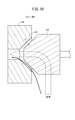
- a turbine side of a turbocharger includes an impeller 102 having a blade 100 and a metal shroud 104 covering the blade 100 of the impeller 102 as shown in FIG.
- the impeller 102 is rotated by the pressure of the exhaust gas flowing in from the exhaust inlet, and the rotational energy can be recovered by the compressor.
- the exhaust gas does not rotate the impeller 102 and passes through the gap (clearance d) between the shroud 104 and the impeller 102, thereby reducing the energy recovery rate.
- This problem also occurs between the compressor-side impeller 102 and the shroud 104. Therefore, conventionally, efforts have been made to make the clearance d between the impeller 102 and the shroud 104 as small as possible.
- Japanese Patent Laid-Open No. 2-196109 describes an example in which a ceramic seal layer bonded with a porous ceramic is joined to a metal shroud via an intermediate layer that absorbs a difference in thermal expansion.
- Japanese Patent Application Laid-Open No. 6-39820 discusses shrink fitting.
- a sliding member made of resin is adopted as a part of the shroud on the compressor side. Since the compressor side has a low temperature (about 200 ° C.) as compared with the turbine side, a resin sliding member can be used. However, since the turbine side becomes a high temperature (800 ° C. or higher), the resin sliding member does not have heat resistance.
- a ceramic seal layer is employed as an abradable seal on a metal shroud.
- thermal stress is generated due to a difference in thermal expansion coefficient between the ceramic and the metal.
- a crack may arise in the joining interface of a shroud and a ceramic seal layer, or peeling may arise and a position may shift.
- the clearance between the original target impeller and the shroud cannot be reduced.
- An intermediate layer is interposed to relieve the thermal stress, but there is also a problem that the thermal stress is too large to be alleviated.
- the present invention has been made in consideration of such a problem.
- a metal shroud is provided with a ceramic member, and the clearance between the impeller and the shroud is almost zero before and after the temperature rise. It is an object of the present invention to provide a shroud structure that can be maintained and can suppress a reduction in energy recovery rate in a turbocharger.
- the present invention provides a turbocharger that can maintain the clearance between the impeller and the shroud at a clearance that is substantially close to zero before and after the temperature rise, and that can suppress a decrease in the energy recovery rate. Objective.
- a shroud structure is a shroud structure including a metal shroud that covers a blade among impellers that are rotationally driven by the pressure of exhaust gas, and includes the shroud and the shroud. And a ceramic member attached at a position facing the blade of the impeller, and a pressing member that presses the ceramic member toward the shroud.
- the shroud has at least one first inclined surface at a portion to which the ceramic member is attached, and the ceramic member faces the first inclined surface of the shroud. You may have at least 1 2nd inclined surface.
- the first inclined surface and the second inclined surface have the same angle with respect to the pressing direction by the pressing member.
- the first inclined surface and the second inclined surface may have an angle of more than 0 ° and less than 90 ° with respect to the pressing direction by the pressing member.
- the pressing direction by the pressing member may be a direction along the axial direction of the impeller and away from the impeller.
- the pressing member presses an exposed surface of the ceramic member that does not face the blade of the impeller.
- the pressing member has a metal member that is in contact with the exposed surface of the ceramic member and is fixed to the shroud at a low temperature portion, and the metal member is a metal that constitutes the shroud. It is preferable to have a coefficient of thermal expansion higher than that of the material.
- the shroud may include a member that fixes a surface of the metal member opposite to a surface that contacts the exposed surface of the ceramic member.
- the shroud includes a first projecting portion that projects toward the metal member
- the metal member includes a second projecting portion that projects toward the shroud
- the pressing member includes: Furthermore, you may have a clamp member which fastens the front-end
- the shroud has a plurality of the first inclined surfaces
- the ceramic member has a plurality of the second inclined surfaces
- the ceramic member preferably has a porosity of 1 to 80%.
- the porosity of the ceramic member is preferably such that the porosity of the portion facing the shroud is lower than the porosity of the portion facing the blade of the impeller.
- the ceramic member preferably has a thermal expansion coefficient of 0.1 to 18.0 ⁇ 10 ⁇ 6 / K.
- a lubricant may be interposed between the shroud and the ceramic member.
- a turbocharger is the turbocharger having an impeller that is rotationally driven by the pressure of exhaust gas and a metal shroud that covers a blade of the impeller. It has a ceramic member attached to the position facing the blade of the impeller, and a pressing member that presses the ceramic member toward the shroud.
- the impeller may be a turbine impeller installed on a turbine side
- the shroud may be a turbine shroud installed in a turbine.
- the metal shroud is provided with the ceramic member, and the clearance between the impeller and the shroud can be maintained at a nearly zero clearance before and after the temperature rise. A decrease in the energy recovery rate in the charger can be suppressed.
- the clearance between the impeller and the shroud can be maintained at nearly zero clearance before and after the temperature rise, and the reduction in energy recovery rate can be suppressed.
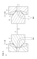
- FIG. 1 is a cross-sectional view showing a schematic configuration of the turbocharger according to the present embodiment with a part thereof omitted.
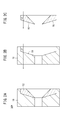
- FIG. 2A is a cross-sectional view showing the shroud structure (first shroud structure) according to the first embodiment.
- FIG. 2B is a cross-sectional view showing the turbine shroud of the first shroud structure.
- FIG. 2C is a cross-sectional view showing a ceramic member of the first shroud structure.
- FIG. 3A is a cross-sectional view of the first shroud structure with a part of the state before the temperature rise omitted.
- FIG. 3B is a cross-sectional view showing a part of the first shroud structure after the temperature is partially omitted.
- FIG. 1 is a cross-sectional view showing a schematic configuration of the turbocharger according to the present embodiment with a part thereof omitted.
- FIG. 2A is a cross-sectional view showing the shroud structure (first shrou
- FIG. 4A is a cross-sectional view showing the first shroud structure including the first pressing member with a part thereof omitted.
- FIG. 4B is a cross-sectional view showing a part of the first shroud structure including the second pressing member.
- FIG. 5A is a cross-sectional view illustrating a shroud structure (second shroud structure) according to the second embodiment with a part thereof omitted.
- FIG. 5B is a cross-sectional view showing the turbine shroud of the second shroud structure.
- FIG. 5C is a cross-sectional view showing a ceramic member of the second shroud structure.
- FIG. 6A is a cross-sectional view illustrating a shroud structure (third shroud structure) according to the third embodiment with a part thereof omitted.
- FIG. 6B is a cross-sectional view showing the turbine shroud of the third shroud structure.
- FIG. 6C is a cross-sectional view showing a ceramic member of the third shroud structure.
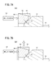
- FIG. 7A is a cross-sectional view showing a state of the third shroud structure before temperature elevation with a part omitted.
- FIG. 7B is a cross-sectional view showing a part of the third shroud structure after the temperature is partially omitted.
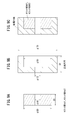
- FIG. 8A is a cross-sectional view illustrating the configuration of the ceramic member 1 (or ceramic member 2) according to the first embodiment.
- FIG. 8B is a cross-sectional view illustrating the configuration of the metal cylinder according to the first embodiment.
- FIG. 8C is a cross-sectional view illustrating a state in which the ceramic member 1 (or the ceramic member 2) is fitted to the inner peripheral surface of the metal cylinder in the first embodiment.
- FIG. 9A is a cross-sectional view showing a configuration of a ceramic member 1 (or ceramic member 2) according to Comparative Example 1.
- FIG. 9B is a cross-sectional view illustrating a configuration of a metal cylinder according to Comparative Example 1.
- FIG. 9C is a cross-sectional view illustrating a state in which the ceramic member 1 (or the ceramic member 2) is fitted to the inner peripheral surface of the metal cylinder in the first comparative example. It is explanatory drawing which shows the effect
- a turbocharger 10 includes a metal turbine impeller 12 that is driven to rotate by exhaust pressure on the turbine side, and a blade 14 portion of the turbine impeller 12.
- a metal turbine shroud 16 is installed.
- a metal compressor impeller 20 connected to the turbine impeller 12 via the rotor shaft 18, and a metal compressor shroud 24 covering the blade 22 portion of the compressor impeller 20 are installed. Yes.
- the turbine impeller 12 is rotated by the pressure of exhaust gas flowing from an exhaust inlet (not shown).
- the rotational force of the turbine impeller 12 is transmitted to the compressor impeller 20 via the rotor shaft 18, and fresh air taken from a fresh air inlet (not shown) passes through a flow path between a plurality of blades 22 provided in the compressor impeller 20. Then, it is compressed and sent to the internal combustion engine.
- the shroud structure 50A according to the first embodiment (hereinafter, referred to as the first shroud structure 50A) is installed, for example, on the turbine side as shown in FIG. 2A, and the metal turbine shroud 16 described above is used. And an annular ceramic member 52 attached to the turbine shroud 16 at a position facing the blade 14 of the turbine impeller 12, and a pressing member 54 (see FIG. 3A) for pressing the ceramic member 52 toward the turbine shroud 16.
- the first shroud structure 50A is installed, for example, on the turbine side as shown in FIG. 2A, and the metal turbine shroud 16 described above is used.
- the ceramic member 52 when the ceramic member 52 is attached to the turbine shroud 16 at room temperature, the ceramic member 52 is attached to the turbine shroud 16 as shown in FIG. 2B. However, as will be described later, when the temperature around the turbine shroud 16 becomes high and the turbine shroud 16 is thermally expanded, the ceramic member 52 slides relative to the turbine shroud 16 (see FIG. 3B).
- the turbine shroud 16 has at least one first inclined surface 58 at a portion where the ceramic member 52 is attached.
- the ceramic member 52 has at least one second inclined surface 60 that faces the first inclined surface 58 of the turbine shroud 16.
- the first inclined surface 58 provided on the turbine shroud 16 and the second inclined surface 60 provided on the ceramic member 52 have the same angle ⁇ with respect to the pressing direction by the pressing member 54.
- the first inclined surface 58 and the second inclined surface 60 have an angle of more than 0 ° and less than 90 °, preferably 30 with respect to the pressing direction by the pressing member 54 (see FIG. 3A).
- the pressing direction by the pressing member 54 is a direction along the axial direction of the turbine impeller 12 and away from the turbine impeller 12, as shown in FIG. 3A.
- the pressing member 54 presses the exposed surface 56 of the ceramic member 52 that does not face the blade 14 of the turbine impeller 12. A specific configuration example of the pressing member 54 will be described later.
- the first inclined surface 58 provided in the turbine shroud 16 and the second inclined surface 60 provided in the ceramic member 52 have the same angle ⁇ with respect to the pressing direction by the pressing member 54. Therefore, the second inclined surface 60 of the ceramic member 52 can slide smoothly with respect to the first inclined surface 58 of the turbine shroud 16, and the occurrence of cracks or the like in the ceramic member 52 can be suppressed.
- the lubricant is interposed between the first inclined surface 58 of the turbine shroud 16 and the second inclined surface 60 of the ceramic member 52, so that the second inclined surface 60 of the ceramic member 52 is further The turbine shroud 16 can be smoothly slid with respect to the first inclined surface 58.
- the pressing member 54 presses the exposed surface 56 of the ceramic member 52 not facing the blade 14 of the turbine impeller 12. Therefore, the pressing member 54 can press the ceramic member 52 toward the turbine shroud 16 without hindering the rotation of the turbine impeller 12.
- the pressing member according to the first configuration example (hereinafter referred to as the first pressing member 54 ⁇ / b> A) is in contact with the exposed surface 56 of the ceramic member 52, and in the low temperature region 64, the turbine shroud. 16 has an annular metal member 62 fixed to 16.
- the metal member 62 has a coefficient of thermal expansion higher than that of the metal material constituting the turbine shroud 16.
- the turbine impeller 12 and its surroundings become high temperature.
- a cylindrical region (indicated by a two-dot chain line) having a diameter substantially the same as the outer diameter of the turbine impeller 12 is the high temperature region 66.
- the turbine shroud 16 has a fixing member 68 that fixes a surface of the metal member 62 opposite to the surface that contacts the exposed surface 56 of the ceramic member 52.
- the fixing member 68 is formed integrally with the turbine shroud 16, for example, and has an annular outer wall 68 a extending from the outer peripheral portion of the turbine shroud 16 toward the compressor, and an annular fixing wall extending from the end of the outer wall 68 a toward the turbine impeller 12. 68b.
- the metal member 62 is installed in an annular space formed between the exposed surface 56 of the ceramic member 52, the inner surface of the outer wall 68 a of the fixing member 68, and the fixing wall 68 b of the fixing member 68.
- the metal member 62 Since the coefficient of thermal expansion of the metal member 62 is higher than the coefficient of thermal expansion of the metal material constituting the turbine shroud 16, the metal member 62 expands to some extent even if the turbine shroud 16 hardly thermally expands.
- the member 52 can be pressed toward the turbine shroud 16.
- the metal member 62 presses the ceramic member 52 toward the turbine shroud 16 even at room temperature.
- the metal member 62 only needs to have a higher thermal expansion coefficient than that of the metal material constituting the turbine shroud 16, and may be a metal material different from the metal material constituting the turbine shroud 16, or the same kind of metal material. Good.
- the pressing member according to the second configuration example (hereinafter referred to as the second pressing member 54B) is a metal member 62 similar to the metal member 62 of the first pressing member 54A described above. Although it is the same in terms of use, it differs in the following points.
- the turbine shroud 16 has a first projecting portion 70 that projects from the rear portion (compressor side) toward the metal member 62 and in a direction away from the high temperature region 66.
- the metal member 62 has a thick flange portion 72 at the rear (compressor side), a thin cylindrical portion 74 protruding from the flange portion 72 toward the exposed surface 56 of the ceramic member 52, A second projecting portion 76 projecting from the boundary portion of the cylindrical portion 74 toward the first projecting portion 70 of the turbine shroud 16 and in a direction away from the high temperature region 66 is provided.
- the second pressing member 54 ⁇ / b> B has a clamp member 78 that fastens the distal end portion of the first projecting portion 70 and the distal end portion of the second projecting portion 76 in the low temperature region 64.
- a commercially available clamp center ring etc. can be used, for example.
- the metal member 62 can be fixed to the turbine shroud 16 in the low temperature region 64 by fastening the tip of the first overhang 70 and the tip of the second overhang 76.
- the fastening can be performed in the low temperature region 64 that is separated from the high temperature region 66, there is an advantage that the fastening force is difficult to loosen.
- the thermal expansion coefficient of the metal member 62 is higher than the thermal expansion coefficient of the metal material constituting the turbine shroud 16. Therefore, even if the turbine shroud 16 hardly thermally expands, the metal member 62 thermally expands to some extent. Therefore, the ceramic member 52 can be pressed toward the turbine shroud 16 through the cylindrical shape of the metal member 62. . Even at room temperature, the metal member 62 presses the ceramic member 52 against the turbine shroud 16. Similarly to the first pressing member 54A, the metal member 62 only needs to have a higher thermal expansion coefficient than that of the metal material constituting the turbine shroud 16, and is different from the metal material constituting the turbine shroud 16. However, the same kind of metal material may be used.
- a shroud structure according to the second embodiment (hereinafter referred to as a second shroud structure 50B) will be described with reference to FIGS. 5A and 5B.
- the second shroud structure 50B has substantially the same configuration as the first shroud structure 50A described above, but differs in the following points.
- the turbine shroud 16 has two first inclined surfaces 58 (a first inclined surface 58a on the outer peripheral side and a first inclined surface 58b on the inner peripheral side).
- the ceramic member 52 has two second inclined surfaces 60 (a second inclined surface 60a on the outer peripheral side and a second inclined surface 60b on the inner peripheral side).
- the ceramic member 52 has a step 80 between the two second inclined surfaces 60.
- the step 80 extends in a direction away from the exposed surface 56.
- the size and material of the metal member 62 must be selected in consideration of the thermal expansion of the metal member 62 and the amount of change of the ceramic member 52.
- the amount of change of the ceramic member 52 is small, it is only necessary to select the size and material of the metal member 62 in consideration of only the thermal expansion of the metal member 62. Therefore, it is possible to select various materials and freedom of design. It is possible to increase the degree and reduce the material cost.
- FIGS. 5A and 5B the example in which the first pressing member 54A is adopted is shown, but the same effect can be obtained even if the second pressing member 54B (see FIG. 4B) is adopted.
- a shroud structure (hereinafter referred to as a third shroud structure 50C) according to a third embodiment will be described with reference to FIGS. 6A to 7B.
- the third shroud structure 50C has substantially the same configuration as the first shroud structure 50A described above, but differs in the following points.
- the turbine shroud 16 has a structure in which the thickness gradually increases toward the turbine impeller 12 (see FIG. 7A), and the inner peripheral surface itself constitutes the first inclined surface 58.
- the ceramic member 52 is installed in the turbine shroud 16, and the outer peripheral surface itself constitutes the second inclined surface 60.
- the pressing member 54 presses the exposed surface 56 of the ceramic member 52 that does not face the blade 14 of the turbine impeller 12. In this case, the pressing direction of the turbine impeller 12 is Along the axial direction and toward the turbine impeller 12.
- the first inclined surface 58 and the second inclined surface 60 have the same angle with respect to the pressing direction by the pressing member 54, an angle of more than 0 ° and less than 90 °, preferably an angle of 30 ° or more and less than 90 °, More preferably, it has an angle of 60 ° or more and less than 90 °.
- the ceramic member 52 is pressed toward the turbine shroud 16 by the pressing member 54. Therefore, when the turbine shroud 16 expands in the radial direction due to thermal expansion, the second inclined surface 60 of the ceramic member 52 slides along the first inclined surface 58 of the turbine shroud 16, against the expansion of the turbine shroud 16. Maintain the shape before temperature rise. That is, the ceramic member 52 maintains the position before the temperature rise without breaking. As a result, even when the temperature of the turbine shroud 16 and its surroundings is high, a clearance d that is almost zero is maintained between the blade 14 of the turbine impeller 12 and the ceramic member 52, and the energy associated with the increase of the clearance d is increased. A reduction in recovery rate can be suppressed.
- the first pressing member 54A or the second pressing member 54B described above can be preferably employed.
- the porosity of the ceramic member 52 is 1 to 80%, preferably 10 to 70%, and more preferably 20 to 60%. If the porosity is low, that is, it is dense, the ceramic member 52 cannot be scraped by the blades 14 of the turbine impeller 12, and the blades 14 of the turbine impeller 12 may be damaged. On the other hand, if the porosity is too high, the mechanical strength is weakened, and there is a risk of damage due to pressing by the pressing member 54.
- the porosity of the ceramic member 52 is preferably such that the porosity of the portion facing the turbine shroud 16 is lower than the porosity of the portion facing the blade 14 of the turbine impeller 12. If the porosity of the portion facing the turbine shroud 16 is high, the ceramic member 52 may be scraped when attached to the turbine shroud 16, and the dimensions may change. If the porosity of the portion of the turbine impeller 12 facing the blade 14 is low, the blade 14 may be damaged.
- the thermal expansion coefficient of the ceramic member 52 is 0.1 to 18.0 ⁇ 10 ⁇ 6 / K, preferably 0.5 to 11.0 ⁇ 10 ⁇ 6 / K, more preferably 1 to 5.0 ⁇ 10 ⁇ . 6 / K. If the coefficient of thermal expansion is too low, the dimensional difference from the turbine shroud 16 (made of metal) having a high coefficient of thermal expansion greatly increases when the temperature is raised, and the first inclined surface 58 and the second inclined surface 60 slide with each other. It may not be possible to absorb the dimensional difference. If the thermal expansion coefficient is too high, cracking may occur due to thermal stress generated by the temperature difference of the ceramic member 52 itself when the temperature is raised.
- machinable ceramic such as mica, talc, titanium silicon carbide, boron nitride, or a mixture including at least one of these materials.
- nickel alloy such as Inconel (registered trademark), Hastelloy (registered trademark), or the like. Due to its high heat resistance, it is suitable for high temperature (800 ° C or higher) use environment.
- Example 1 Porous by yttria partially stabilized zirconia powder uniaxial press molding, CIP (cold isostatic pressing method) to produce cylindrical pellets, followed by firing in air at 1200 ° C for 2 hours A ceramic cylinder was obtained. By machining this, as shown in FIG. 8A, the outer diameter of one end is ⁇ 30 mm, the outer diameter of the other end is ⁇ 70 mm, and the inner diameter is constant ⁇ 30 mm from one end to the other end. Thus, a cylindrical ceramic member 1 having a distance (height) from one end to the other end of 20 mm was obtained. The inclination angle of the outer peripheral surface is 45 °.
- the porosity of the ceramic member 1 was 50% as measured by Archimedes method (JIS 1634-1998).
- the coefficient of thermal expansion was 10.5 ⁇ 10 ⁇ 6 / K as measured according to JIS1618-2002.
- Ceramic Member 2 A yttria partially stabilized zirconia powder was mixed with a solvent, poured into a mold, dried, and fired at 1200 ° C. for 2 hours to obtain a ceramic member 2 having the same shape as the ceramic member 1 described above.
- the porosity was 50% and the thermal expansion coefficient was 10.5 ⁇ 10 ⁇ 6 / K.
- Metal cylinder As shown in FIG. 8B, a metal cylinder having a shape in which the inner diameter expands from one end to the other end was prepared.
- the inner diameter of one end is ⁇ 10 mm, and the inner diameter of the other end is ⁇ 70 mm.
- the outer diameter is a constant ⁇ 70 mm from one end to the other end.
- the distance (height) from one end to the other end is 30 mm.
- the inclination angle of the inner peripheral surface is 45 °.
- the thermal expansion coefficient of the metal cylinder was 12.0 ⁇ 10 ⁇ 6 / K.
- the ceramic member 2 was fixed by pressing it with a pressure of 10 MPa. In this state, the temperature of the metal cylinder and the entire ceramic member 2 was increased to 500 ° C. After the temperature rise, it was inspected whether the ceramic member 2 was peeled off or cracked. The same inspection was performed after the temperature was lowered to room temperature.
- Example 2 Ceramic member 1 and ceramic member 2 (thermal expansion coefficient 2.8 ⁇ 10 ⁇ 6 / K) were made of silicon nitride. That is, the ceramic member 1 and the ceramic member in the same manner as in Example 1 except that silicon nitride was used as a raw material, yttria was used as an auxiliary, alumina was used, and a resin was used as a pore-forming agent. 2 was produced. And it experimented by the method similar to Example 1. FIG.
- Example 3 The experiment was performed in the same manner as in Example 1 except that the inclination angle of the ceramic member 1, the ceramic member 2, and the metal cylinder was set to 10 °.
- Example 4 The ceramic member 1 and the ceramic member 2 (thermal expansion coefficient 2.8 ⁇ 10 ⁇ 6 / K) are made of silicon nitride, except that the inclination angle of the ceramic member 1, the ceramic member 2 and the metal cylinder is 10 °. The experiment was conducted in the same manner as in Example 1.
- Example 5 The experiment was performed in the same manner as in Example 1 except that the inclination angle of the ceramic member 1, the ceramic member 2, and the metal cylinder was set to 80 °.
- Example 6 The ceramic member 1 and the ceramic member 2 (thermal expansion coefficient 2.8 ⁇ 10 ⁇ 6 / K) are made of silicon nitride, except that the inclination angle of the ceramic member 1, the ceramic member 2 and the metal cylinder is 80 °. The experiment was conducted in the same manner as in Example 1.
- Example 7 Ceramic member 1 and ceramic member 2 (thermal expansion coefficient 2.8 ⁇ 10 ⁇ 6 / K) are made of silicon nitride, the porosity of ceramic member 1 and ceramic member 2 is 30%, ceramic member 1, ceramic member 2 and The experiment was performed in the same manner as in Example 1 except that the inclination angle of the metal cylinder was 80 °.
- Example 8 Ceramic member 1 and ceramic member 2 (thermal expansion coefficient 2.8 ⁇ 10 ⁇ 6 / K) are made of silicon nitride, the porosity of ceramic member 1 and ceramic member 2 is 60%, ceramic member 1, ceramic member 2 and The experiment was performed in the same manner as in Example 1 except that the inclination angle of the metal cylinder was 80 °.
- Example 9 Ceramic member 1 and ceramic member 2 (thermal expansion coefficient 2.8 ⁇ 10 ⁇ 6 / K) are made of silicon nitride, the porosity of ceramic member 1 and ceramic member 2 is 60%, ceramic member 1, ceramic member 2 and The experiment was performed in the same manner as in Example 1 except that the inclination angle of the metal cylinder was 88 °.
- Ceramic member 1 and ceramic member 2 (thermal expansion coefficient 2.8 ⁇ 10 ⁇ 6 / K) are made of silicon nitride, the porosity of ceramic member 1 and ceramic member 2 is 60%, ceramic member 1, ceramic member 2 and The experiment was performed in the same manner as in Example 1 except that the inclination angle of the metal cylinder was 60 °.
- Ceramic member 1 and ceramic member 2 (coefficient of thermal expansion 4.5 ⁇ 10 ⁇ 6 / K) were made of silicon carbide and silicon. That is, ceramic member 1 and ceramic member 2 were produced in the same manner as in Example 1 except that silicon carbide and silicon were used as raw materials and resin was used as a pore-forming agent, and firing was performed at 1430 ° C. for 2 hours in an argon atmosphere. And it experimented by the method similar to Example 1 except the porosity of the ceramic member 1 and the ceramic member 2 having been 60%, and the inclination angle of the ceramic member 1, the ceramic member 2, and the metal cylinder having been 80 degrees. .
- Example 12 Ceramic member 1 and ceramic member 2 (coefficient of thermal expansion 1.5 ⁇ 10 ⁇ 6 / K) were prepared using cordierite. That is, the ceramic member 1 and the ceramic member 2 were prepared in the same manner as in Example 1 except that talc, alumina, kaolin, silica as a raw material and resin as a pore-forming agent were fired at 1420 ° C. for 2 hours in an air atmosphere. Produced. And it experimented by the method similar to Example 1 except the porosity of the ceramic member 1 and the ceramic member 2 having been 60%, and the inclination angle of the ceramic member 1, the ceramic member 2, and the metal cylinder having been 80 degrees. .
- the outer diameter is a constant ⁇ 50 mm from one end to the other end
- the inner diameter is a constant ⁇ 10 mm from one end to the other end.
- the cylinder was 20 mm in height.
- the outer diameter was a constant ⁇ 70 mm from one end to the other end.
- the inner diameter was changed in two steps. That is, the inner diameter of a portion extending from one end portion to 10 mm toward the other end portion was ⁇ 10 mm, and the inner diameter portion of the portion extending from the other end portion to 20 mm toward one end portion was ⁇ 50 mm.
- the distance (height) from one end to the other was 30 mm. That is, it has the structure where the recessed part for inserting the ceramic member 1 or the ceramic member 2 was formed in the other edge part of a metal cylinder.
- the ceramic member 1 was fixed by pressing it with a pressure of 10 MPa. In this state, the temperature of the metal cylinder and the entire ceramic member 1 was increased to 500 ° C. After the temperature increase, it was inspected whether the ceramic member 1 was peeled off or cracked. The same inspection was performed after the temperature was lowered to room temperature. A similar experiment was conducted on the ceramic member 2.
- the ceramic member 1 assuming the ceramic member 52 and the ceramic member 2 are fitted to the inner peripheral surface of the metal cylinder assuming the turbine shroud 16, that is, all of Examples 1 to 12 are ceramic.
- the member 1 and the ceramic member 2 were not peeled off or cracked.
- shroud structure and the turbocharger according to the present invention are not limited to the above-described embodiments, and can of course have various configurations without departing from the gist of the present invention.
- the shroud structure may be applied to the compressor shroud 24 on the compressor side (see FIG. 1). Even if it says low temperature, it is about 200 degreeC and is high temperature compared with room temperature (25 degreeC). Even in such an environment, by applying the shroud structure according to the present embodiment, the clearance between the ceramic member 52 installed in the compressor shroud 24 and the blade 22 of the compressor impeller 20 is constant regardless of temperature changes. And the effect of suppressing the decrease in energy efficiency can be further enhanced.
- the configuration of the shroud structure and the turbocharger according to the present invention can be diverted to a gas turbine.
Landscapes
- Engineering & Computer Science (AREA)
- Chemical & Material Sciences (AREA)
- Combustion & Propulsion (AREA)
- Mechanical Engineering (AREA)
- General Engineering & Computer Science (AREA)
- Supercharger (AREA)
Abstract
本発明は、ターボチャージャに設置されるシュラウド構造体に関する。シュラウド構造体(50A)は、排気の圧力によって回転駆動するタービンインペラ(12)のうち、ブレード(14)を覆う金属製のタービンシュラウド(16)と、タービンインペラ(12)のブレード(14)と対向する位置に取り付けられたセラミック部材(52)と、セラミック部材(52)をタービンシュラウド(16)に向けて押し付ける押し付け部材(54)とを有する。
Description
本発明は、ターボチャージャに設置されるシュラウド構造体及びターボチャージャに関する。
一般に、ターボチャージャの例えばタービン側は、図10に示すように、ブレード100を有するインペラ102と、該インペラ102のブレード100を覆う金属製のシュラウド104とを備えている。通常、排気入口から流入した排気の圧力によって、インペラ102を回転させ、その回転エネルギーをコンプレッサで回収することができればよい。しかし、排気がインペラ102を回転させずに、シュラウド104とインペラ102間の隙間(クリアランスd)を通過してしまい、エネルギーの回収率が低下するという問題がある。この問題は、コンプレッサ側のインペラ102とシュラウド104との間でも生じている。そこで、従来から、インペラ102とシュラウド104間のクリアランスdをできるだけ小さくするための取り組みが行われている。
例えば特許第3639846号公報では、コンプレッサ側において、金属材料を摩耗させない樹脂で構成された滑り部材をシュラウドの一部に採用(アブレーダブルシール:abradable seal)することで、上述のクリアランスをほぼゼロにしている。
特開平2-196109号公報では、金属製のシュラウド上に、多孔質セラミックにて結合したセラミックシール層を、熱膨張差を吸収する中間層を介して接合した例が記載されている。また、特開平6-39820号公報では、焼きばめが検討されている。
ところで、特許第3639846号公報に記載の方法は、コンプレッサ側において、樹脂で構成された滑り部材をシュラウドの一部に採用している。コンプレッサ側は、タービン側と比して低温(200℃程度)であるため、樹脂製の滑り部材を使用することができる。しかし、タービン側は、高温(800℃以上)になるため、樹脂製の滑り部材では耐熱性が持たない。
特開平2-196109号公報に記載の方法では、金属製のシュラウド上にセラミックシール層をアブレーダブルシールとして採用している。しかし、室温から高温に昇温した際に、セラミックと金属との熱膨張係数差で熱応力が発生する。これにより、シュラウドとセラミックシール層との接合界面で割れが生じたり、剥がれが生じ、位置がずれるおそれがある。この場合、本来の目的のインペラとシュラウド間のクリアランスを小さくすることができなくなる。熱応力を緩和するために中間層を介在させているが、熱応力が大きすぎて緩和しきれないという問題もある。
特開平6-39820号公報に記載の方法では、焼きばめが検討されている。しかし、室温から高温に昇温した際に、金属部材が大きく膨らむ一方で、セラミック部材はほとんど膨らまないため、金属部材とセラミック部材間にギャップが発生する。この場合、セラミック部材が位置ずれを起こし、本来の目的であるインペラとシュラウド間のクリアランスを小さくすることができなくなるおそれがある。場合によっては、回転軸ずれによるインペラとの干渉、磨耗によって、クリアランスがさらに大きくなるおそれもある。
このように、セラミック部材を金属部材にクリアランスを小さい状態に保ったまま固定したいが、化学的、物理的に固定(接合)する上述の2つの手法のどちらにおいても課題がある。
本発明はこのような課題を考慮してなされたものであり、金属製のシュラウドにセラミック部材を具備させ、且つ、昇温の前後において、インペラとシュラウド間のクリアランスを、ほぼゼロに近いクリアランスに維持させることができ、ターボチャージャにおけるエネルギーの回収率の低下を抑えることができるシュラウド構造体を提供することを目的とする。
また、本発明は、昇温の前後において、インペラとシュラウド間のクリアランスを、ほぼゼロに近いクリアランスに維持させることができ、エネルギーの回収率の低下を抑えることができるターボチャージャを提供することを目的とする。
[1] 第1の本発明に係るシュラウド構造体は、排気の圧力によって回転駆動するインペラのうち、ブレードを覆う金属製のシュラウドを有するシュラウド構造体であって、前記シュラウドと、前記シュラウドのうち、前記インペラのブレードと対向する位置に取り付けられたセラミック部材と、前記セラミック部材を前記シュラウドに向けて押し付ける押し付け部材とを有することを特徴とする。
[2] 第1の本発明において、前記シュラウドは、前記セラミック部材が取り付けられた部分に少なくとも1つの第1傾斜面を有し、前記セラミック部材は、前記シュラウドの前記第1傾斜面に対向する少なくとも1つの第2傾斜面を有してもよい。
[3] この場合、前記第1傾斜面及び前記第2傾斜面は、前記押し付け部材による押し付け方向に対して同じ角度を有することが好ましい。
[4] また、前記第1傾斜面及び前記第2傾斜面は、前記押し付け部材による押し付け方向に対して0°を超えて90°未満の角度を有してもよい。
[5] 第1の本発明において、前記押し付け部材による押し付け方向が、前記インペラの軸方向に沿い、且つ、前記インペラから遠ざかる方向であってもよい。
[6] 第1の本発明において、前記押し付け部材による押し付け方向が、前記インペラの軸方向に沿い、且つ、前記インペラに向かう方向であってもよい。
[7] 第1の本発明において、前記押し付け部材は、前記セラミック部材のうち、前記インペラのブレードに対向していない露出面を押し付けることが好ましい。
[8] この場合、前記押し付け部材は、前記セラミック部材の前記露出面に接触し、且つ、低温部分において前記シュラウドに固定された金属部材を有し、前記金属部材は、前記シュラウドを構成する金属材料の熱膨張係数よりも高い熱膨張係数を有することが好ましい。
[9] さらに、前記シュラウドは、前記金属部材のうち、前記セラミック部材の前記露出面に接触する面と反対の面を固定する部材を有してもよい。
[10] あるいは、前記シュラウドは、前記金属部材に向かって張り出す第1張り出し部を有し、前記金属部材は、前記シュラウドに向かって張り出す第2張り出し部を有し、前記押し付け部材は、さらに、前記第1張り出し部の先端部と前記第2張り出し部の先端部を締結するクランプ部材を有してもよい。
[11] また、前記シュラウドは、複数の前記第1傾斜面を有し、前記セラミック部材は、複数の前記第2傾斜面を有し、且つ、複数の前記第2傾斜面間に段差を有し、前記段差は、前記露出面から遠ざかる方向に延びていてもよい。
[12] 第1の本発明において、前記セラミック部材の気孔率は1~80%であることが好ましい。
[13] この場合、前記セラミック部材の気孔率は、シュラウドと対向する部分の気孔率が、インペラのブレードと対向する部分の気孔率より低いことが好ましい。
[14] 第1の本発明において、前記セラミック部材の熱膨張係数は0.1~18.0×10⁻⁶/Kであることが好ましい。
[15] 第1の本発明において、前記シュラウドと前記セラミック部材との間に潤滑剤が介在されていてもよい。
[16] 第2の本発明に係るターボチャージャは、排気の圧力によって回転駆動するインペラと、該インペラのブレードを覆う金属製のシュラウドとを有するターボチャージャにおいて、前記シュラウドと、前記シュラウドのうち、前記インペラのブレードと対向する位置に取り付けられたセラミック部材と、前記セラミック部材を前記シュラウドに向けて押し付ける押し付け部材とを有することを特徴とする。
[17] 第2の本発明において、前記インペラがタービン側に設置されるタービンインペラであり、前記シュラウドがタービンに設置されるタービンシュラウドであってもよい。
本発明に係るシュラウド構造体によれば、金属製のシュラウドにセラミック部材を具備させ、且つ、昇温の前後において、インペラとシュラウド間のクリアランスをほぼゼロに近いクリアランスに維持させることができ、ターボチャージャにおけるエネルギーの回収率の低下を抑えることができる。
本発明に係るターボチャージャによれば、昇温の前後において、インペラとシュラウド間のクリアランスをほぼゼロに近いクリアランスに維持させることができ、エネルギーの回収率の低下を抑えることができる。
以下、本発明に係るシュラウド構造体及びターボチャージャの実施の形態例を図1~図9Cを参照しながら説明する。
先ず、本実施の形態に係るターボチャージャ10は、図1に示すように、タービン側に、排気の圧力によって回転駆動する金属製のタービンインペラ12と、該タービンインペラ12のうち、ブレード14の部分を覆う金属製のタービンシュラウド16とが設置されている。コンプレッサ側には、タービンインペラ12とローターシャフト18を介して連結された金属製のコンプレッサインペラ20と、該コンプレッサインペラ20のうち、ブレード22の部分を覆う金属製のコンプレッサシュラウド24とが設置されている。
このターボチャージャ10は、図示しない排気入口から流入した排気の圧力によってタービンインペラ12が回転する。タービンインペラ12の回転力は、ローターシャフト18を介してコンプレッサインペラ20に伝わり、図示しない新気入口から取り入れた新気は、コンプレッサインペラ20に設けられた複数のブレード22の間の流路を通り、圧縮されつつ内燃機関へと圧送される。
そして、第1の実施の形態に係るシュラウド構造体50A(以下、第1シュラウド構造体50Aを記す)は、図2Aに示すように、例えばタービン側に設置され、上述した金属製のタービンシュラウド16と、タービンシュラウド16のうち、タービンインペラ12のブレード14と対向する位置に取り付けられた環状のセラミック部材52と、セラミック部材52をタービンシュラウド16に向けて押し付ける押し付け部材54(図3A参照)とを有する。
例えば室温下でタービンシュラウド16にセラミック部材52を取り付ける場合には、図2Bに示すように、タービンシュラウド16にセラミック部材52を嵌め込む形態で取り付けられる。しかし、後述するように、タービンシュラウド16の周辺が高温となって、タービンシュラウド16が熱膨張すると、セラミック部材52はタービンシュラウド16に対して摺動することとなる(図3B参照)。
タービンシュラウド16は、セラミック部材52が取り付けられた部分に少なくとも1つの第1傾斜面58を有する。セラミック部材52は、タービンシュラウド16の第1傾斜面58に対向する少なくとも1つの第2傾斜面60を有する。
タービンシュラウド16に設けられた第1傾斜面58及びセラミック部材52に設けられた第2傾斜面60は、押し付け部材54による押し付け方向に対して同じ角度θを有する。この第1シュラウド構造体50Aでは、第1傾斜面58及び第2傾斜面60は、押し付け部材54による押し付け方向(図3A参照)に対して0°を超えて90°未満の角度、好ましくは30°以上90°未満の角度、さらに好ましくは60°以上90°未満の角度を有する。
押し付け部材54による押し付け方向は、図3Aに示すように、タービンインペラ12の軸方向に沿い、且つ、タービンインペラ12から遠ざかる方向である。また、押し付け部材54は、セラミック部材52のうち、タービンインペラ12のブレード14に対向していない露出面56を押し付ける。押し付け部材54の具体的構成例については後述する。
上述のように、タービンシュラウド16のうち、タービンインペラ12のブレード14と対向する位置にセラミック部材52を設置することで、タービンインペラ12のブレード14とセラミック部材52との間には、一定のクリアランスd、すなわち、ほぼゼロに近いクリアランスdが維持されている。
そして、高温の排気が流れ込むことによって、図3Bに示すように、タービンシュラウド16並びにその周辺が昇温すると、タービンシュラウド16は熱膨張によって径方向に拡大する。すなわち、外径、内径が大きくなる。このとき、セラミック部材52は熱膨張係数が小さいため、ほとんど拡大しない。しかも、セラミック部材52は押し付け部材54によってタービンシュラウド16に向かって押し付けられている。そのため、セラミック部材52は、第2傾斜面60がタービンシュラウド16の第1傾斜面58に沿って摺動し、タービンシュラウド16の拡大に抗して昇温前の形状を維持する。すなわち、セラミック部材52は剥離や破壊することなく、昇温前の位置を維持する。その結果、タービンシュラウド16並びにその周辺が高温になっても、タービンインペラ12のブレード14とセラミック部材52との間には、ほぼゼロに近いクリアランスdが維持され、クリアランスdの拡大に伴うエネルギーの回収率の低下を抑制することができる。
特に、タービンシュラウド16に設けられた第1傾斜面58及びセラミック部材52に設けられた第2傾斜面60は、押し付け部材54による押し付け方向に対して同じ角度θを有する。そのため、セラミック部材52の第2傾斜面60は、タービンシュラウド16の第1傾斜面58に対してスムーズに摺動することができ、セラミック部材52に割れ等の発生を抑制することができる。また、図示しないが、タービンシュラウド16の第1傾斜面58とセラミック部材52の第2傾斜面60との間に潤滑剤を介在させることで、さらに、セラミック部材52の第2傾斜面60を、タービンシュラウド16の第1傾斜面58に対してスムーズに摺動させることができる。
また、押し付け部材54によって、セラミック部材52のうち、タービンインペラ12のブレード14に対向していない露出面56を押し付けるようにしている。そのため、押し付け部材54はタービンインペラ12の回転を阻害することなく、セラミック部材52をタービンシュラウド16に向けて押し付けることが可能となる。
ここで、押し付け部材54のいくつかの構成例について図4A及び図4Bを参照しながら説明する。
先ず、第1の構成例に係る押し付け部材(以下、第1押し付け部材54Aと記す)は、図4Aに示すように、セラミック部材52の露出面56に接触し、且つ、低温領域64においてタービンシュラウド16に固定された環状の金属部材62を有する。金属部材62は、タービンシュラウド16を構成する金属材料の熱膨張係数よりも高い熱膨張係数を有する。
タービンインペラ12には高温の排気が供給されることから、タービンインペラ12並びにその周辺部分は高温となる。具体的には、径がタービンインペラ12の外径とほぼ同じ筒状の領域(二点鎖線で示す)が高温領域66となる。高温領域66から離れれば離れるほど低温になる。従って、高温領域66の外側は、供給される排気によってほとんど昇温しない部分、すなわち、低温領域64と称することができる。
一方、タービンシュラウド16は、金属部材62のうち、セラミック部材52の露出面56に接触する面と反対の面を固定する固定部材68を有する。この固定部材68は、例えばタービンシュラウド16と一体に形成され、タービンシュラウド16の外周部分からコンプレッサ側に延びる環状の外壁68aと、外壁68aの端部からタービンインペラ12に向かって延びる環状の固定壁68bとを有する。金属部材62は、セラミック部材52の露出面56と固定部材68の上記外壁68aの内面と固定部材68の上記固定壁68bとの間に形成される環状の空間に設置される。
金属部材62の熱膨張係数は、タービンシュラウド16を構成する金属材料の熱膨張係数よりも高いため、タービンシュラウド16がほとんど熱膨張しなくても、金属部材62はある程度熱膨張することから、セラミック部材52をタービンシュラウド16に向かって押し付けることが可能となる。もちろん、室温の際にも、金属部材62はセラミック部材52をタービンシュラウド16に向かって押し付けている。なお、金属部材62は、熱膨張係数がタービンシュラウド16を構成する金属材料の熱膨張係数よりも高ければよく、タービンシュラウド16を構成する金属材料と異なる金属材料でもよいし、同種の金属材料でもよい。
次に、第2の構成例に係る押し付け部材(以下、第2押し付け部材54Bと記す)は、図4Bに示すように、上述した第1押し付け部材54Aの金属部材62と同様の金属部材62を用いる点では同じであるが、以下の点で異なる。
すなわち、タービンシュラウド16は、後部(コンプレッサ側)から金属部材62に向かって、且つ、高温領域66から離間する方向に張り出す第1張り出し部70を有する。
金属部材62は、後部(コンプレッサ側)に厚肉のフランジ部72を有し、このフランジ部72からセラミック部材52の露出面56に向かって突出する薄肉の筒状部74と、フランジ部72と筒状部74の境界部分からタービンシュラウド16の第1張り出し部70に向かって、且つ、高温領域66から離間する方向に張り出す第2張り出し部76とを有する。
さらに、第2押し付け部材54Bは、第1張り出し部70の先端部と第2張り出し部76の先端部とを低温領域64で締結するクランプ部材78を有する。クランプ部材78としては、例えば市販のクランプ・センターリング等を用いることができる。
このように、第1張り出し部70の先端部と第2張り出し部76の先端部を締結することによって、低温領域64において金属部材62をタービンシュラウド16に固定することができる。特に、高温領域66から距離を離した低温領域64で締結することができるため、締結力が緩みにくいという利点がある。
この場合も、金属部材62の熱膨張係数は、タービンシュラウド16を構成する金属材料の熱膨張係数よりも高い。そのため、タービンシュラウド16がほとんど熱膨張しなくても、金属部材62はある程度熱膨張することから、金属部材62の筒状を介してセラミック部材52をタービンシュラウド16に向かって押し付けることが可能となる。なお、室温の際にも、金属部材62はセラミック部材52をタービンシュラウド16に向かって押し付けている。また、第1押し付け部材54Aと同様に、金属部材62は、熱膨張係数がタービンシュラウド16を構成する金属材料の熱膨張係数よりも高ければよく、タービンシュラウド16を構成する金属材料と異なる金属材料でもよいし、同種の金属材料でもよい。
次に、第2の実施の形態に係るシュラウド構造体(以下、第2シュラウド構造体50Bと記す)について図5A及び図5Bを参照しながら説明する。
この第2シュラウド構造体50Bは、上述した第1シュラウド構造体50Aとほぼ同様の構成を有するが、以下の点で異なる。
すなわち、図5A~図5Cに示すように、タービンシュラウド16は、2つの第1傾斜面58(外周側の第1傾斜面58a及び内周側の第1傾斜面58b)を有する。セラミック部材52は、2つの第2傾斜面60(外周側の第2傾斜面60a及び内周側の第2傾斜面60b)を有する。また、セラミック部材52は、2つの第2傾斜面60間に段差80を有する。この段差80は、露出面56から遠ざかる方向に延びている。これらの構成によって、露出面56に対向する外周側の第1傾斜面58aの径方向の長さdaを小さくすることができる。そのため、セラミック部材52の熱膨張も考慮した場合に、セラミック部材52の横方向の熱膨張による変化量が小さくなる。
セラミック部材52の熱膨張による変化量が大きいと、金属部材62の熱膨張とセラミック部材52の変化量とを考慮して金属部材62の寸法や材料を選ばなければならない。一方、セラミック部材52の変化量が小さければ、ほとんど金属部材62の熱膨張のみを考慮して金属部材62の寸法や材料を選べばよいため、様々な材料を選ぶことが可能となり、設計の自由度の拡大、材料費の低減等を実現することができる。図5A及び図5Bの例では、第1押し付け部材54Aを採用した例を示したが、第2押し付け部材54B(図4B参照)を採用しても同様の効果を得ることができる。
次に、第3の実施の形態に係るシュラウド構造体(以下、第3シュラウド構造体50Cと記す)について図6A~図7Bを参照しながら説明する。
この第3シュラウド構造体50Cは、図6A~図6C及び図7Aに示すように、上述した第1シュラウド構造体50Aとほぼ同様の構成を有するが、以下の点で異なる。
すなわち、タービンシュラウド16は、タービンインペラ12(図7A参照)に向かって厚みが徐々に厚くなる構造を有し、内周面自体が第1傾斜面58を構成している。セラミック部材52は、タービンシュラウド16内に設置され、その外周面自体が第2傾斜面60を構成している。押し付け部材54は、図7A及び図7Bに示すように、セラミック部材52のうち、タービンインペラ12のブレード14に対向していない露出面56を押し付けるが、この場合、押し付け方向は、タービンインペラ12の軸方向に沿い、且つ、タービンインペラ12に向かう方向である。
第1傾斜面58及び第2傾斜面60は、押し付け部材54による押し付け方向に対して同じ角度を有し、0°を超えて90°未満の角度、好ましくは30°以上90°未満の角度、さらに好ましくは60°以上90°未満の角度を有する。
そして、図7Bに示すように、セラミック部材52は、押し付け部材54によってタービンシュラウド16に向かって押し付けられている。そのため、タービンシュラウド16が熱膨張によって径方向に拡大すると、セラミック部材52の第2傾斜面60がタービンシュラウド16の第1傾斜面58に沿って摺動し、タービンシュラウド16の拡大に抗して昇温前の形状を維持する。すなわち、セラミック部材52は破壊することなく、昇温前の位置を維持する。その結果、タービンシュラウド16並びにその周辺が高温になっても、タービンインペラ12のブレード14とセラミック部材52との間には、ほぼゼロに近いクリアランスdが維持され、クリアランスdの拡大に伴うエネルギーの回収率の低下を抑制することができる。
なお、押し付け部材54の構成例としては、上述した第1押し付け部材54A又は第2押し付け部材54Bを好ましく採用することができる。
上述した第1シュラウド構造体50A~第3シュラウド構造体50Cにおいて、セラミック部材52の気孔率は1~80%、好ましくは10~70%、さらに好ましくは20~60%である。気孔率が低い、すなわち、緻密であると、セラミック部材52をタービンインペラ12のブレード14で削ることができず、タービンインペラ12のブレード14を破損するおそれがある。反対に、気孔率が高すぎると、機械的強度が弱くなり、押し付け部材54による押圧によって破損するおそれがある。
また、セラミック部材52の気孔率は、タービンシュラウド16と対向する部分の気孔率が、タービンインペラ12のブレード14と対向する部分の気孔率より低いことが好ましい。タービンシュラウド16と対向する部分の気孔率が高いと、セラミック部材52をタービンシュラウド16に取り付ける際に削れてしまい、寸法が変化するおそれがある。タービンインペラ12のブレード14と対向する部分の気孔率が低いと、ブレード14を傷つけるおそれがある。
セラミック部材52の熱膨張係数は、0.1~18.0×10⁻⁶/K、好ましくは0.5~11.0×10-6/K、さらに好ましくは1~5.0×10-6/Kである。熱膨張係数が低すぎると、昇温した際に、高熱膨張係数のタービンシュラウド16(金属製)との寸法差が大きく広がってしまい、第1傾斜面58と第2傾斜面60同士の摺動で寸法差を吸収できなくなるおそれがある。また、熱膨張係数が高すぎると、昇温した際に、セラミック部材52自身の温度差で発生する熱応力で割れが生じるおそれがある。
セラミック部材52の構成材料としては、窒化珪素、サイアロン、ジルコニア、コージェライト、炭化珪素、もしくは雲母、タルク、チタンシリコンカーバイド、窒化ホウ素等のマシナブルセラミック、又はこれらの材料を少なくとも1つを含む混合物を好ましく採用することができる。
タービンシュラウド16やタービンインペラ12等の金属部品については、耐熱鋳鋼等、ニッケル合金、例えばインコネル(登録商標)、ハステロイ(登録商標)等を使用することが好ましい。耐熱性が高いため、高温(800℃以上)の使用環境下に適する。
実施例1~12及び比較例1について、セラミック部材の剥がれ、割れを確認した。
(実施例1)
[セラミック部材1の作製]
イットリア部分安定化ジルコニアの粉末を一軸プレス成形、CIP(冷間等方圧加圧法)を施し、円柱のペレットを作製した後に、大気雰囲気中にて1200℃2時間にて焼成することで多孔質セラミックの円柱を得た。これを機械加工することで、図8Aに示すように、一方の端部の外径がφ30mm、他方の端部の外径がφ70mm、内径が一方の端部から他方の端部にかけて一定のφ30mmで、一方の端部から他方の端部までの距離(高さ)が20mmの円筒状のセラミック部材1を得た。外周面の傾斜角は45°である。
[セラミック部材1の作製]
イットリア部分安定化ジルコニアの粉末を一軸プレス成形、CIP(冷間等方圧加圧法)を施し、円柱のペレットを作製した後に、大気雰囲気中にて1200℃2時間にて焼成することで多孔質セラミックの円柱を得た。これを機械加工することで、図8Aに示すように、一方の端部の外径がφ30mm、他方の端部の外径がφ70mm、内径が一方の端部から他方の端部にかけて一定のφ30mmで、一方の端部から他方の端部までの距離(高さ)が20mmの円筒状のセラミック部材1を得た。外周面の傾斜角は45°である。
セラミック部材1の気孔率は、アルキメデス法(JIS1634-1998)で測定したところ、50%であった。熱膨張係数は、JIS1618-2002に準じて測定したところ、10.5×10⁻⁶/Kであった。
[セラミック部材2の作製]
イットリア部分安定化ジルコニアの粉末を溶剤に混ぜた後、型に流し込み、乾燥後1200℃2時間にて焼成することで、上述したセラミック部材1と同様の形状を有するセラミック部材2を得た。セラミック部材2においても、セラミック部材1と同様に、気孔率が50%、熱膨張係数が10.5×10⁻⁶/Kであった。
イットリア部分安定化ジルコニアの粉末を溶剤に混ぜた後、型に流し込み、乾燥後1200℃2時間にて焼成することで、上述したセラミック部材1と同様の形状を有するセラミック部材2を得た。セラミック部材2においても、セラミック部材1と同様に、気孔率が50%、熱膨張係数が10.5×10⁻⁶/Kであった。
[金属円筒]
図8Bに示すように、内径が一方の端部から他方の端部に向かって拡大する形状の金属円筒を用意した。一方の端部の内径がφ10mm、他方の端部の内径がφ70mmである。外径は一方の端部から他方の端部にかけて一定のφ70mmである。一方の端部から他方の端部までの距離(高さ)は30mmである。内周面の傾斜角は45°である。金属円筒の熱膨張係数は12.0×10⁻⁶/Kであった。
図8Bに示すように、内径が一方の端部から他方の端部に向かって拡大する形状の金属円筒を用意した。一方の端部の内径がφ10mm、他方の端部の内径がφ70mmである。外径は一方の端部から他方の端部にかけて一定のφ70mmである。一方の端部から他方の端部までの距離(高さ)は30mmである。内周面の傾斜角は45°である。金属円筒の熱膨張係数は12.0×10⁻⁶/Kであった。
[実験方法]
図8Cに示すように、タービンシュラウド16を想定した金属円筒の内周面に、セラミック部材52を想定したセラミック部材1の外周面を嵌め合せた後、セラミック部材1を1MPaの圧力で押圧することで固定した。この状態で、金属円筒及びセラミック部材1全体を500℃まで昇温した。昇温後、セラミック部材1が剥がれていないか、また、割れていないかどうかを検査した。室温に降温した後にも同様の検査を行った。
図8Cに示すように、タービンシュラウド16を想定した金属円筒の内周面に、セラミック部材52を想定したセラミック部材1の外周面を嵌め合せた後、セラミック部材1を1MPaの圧力で押圧することで固定した。この状態で、金属円筒及びセラミック部材1全体を500℃まで昇温した。昇温後、セラミック部材1が剥がれていないか、また、割れていないかどうかを検査した。室温に降温した後にも同様の検査を行った。
同様に、金属円筒の内周面に今度はセラミック部材2の外周面を嵌め合せた後、セラミック部材2を10MPaの圧力で押圧することで固定した。この状態で、金属円筒及びセラミック部材2全体を500℃まで昇温した。昇温後、セラミック部材2が剥がれていないか、また、割れていないかどうかを検査した。室温に降温した後にも同様の検査を行った。
(実施例2)
窒化珪素でセラミック部材1及びセラミック部材2(熱膨張係数2.8×10⁻⁶/K)を作製した。すなわち、原料として窒化珪素、助剤としてイットリア、アルミナ、造孔剤として樹脂を用いて、窒素雰囲気中で1750℃で2時間焼成した以外は実施例1と同様にして、セラミック部材1及びセラミック部材2を作製した。そして、実施例1と同様の方法で実験を行った。
窒化珪素でセラミック部材1及びセラミック部材2(熱膨張係数2.8×10⁻⁶/K)を作製した。すなわち、原料として窒化珪素、助剤としてイットリア、アルミナ、造孔剤として樹脂を用いて、窒素雰囲気中で1750℃で2時間焼成した以外は実施例1と同様にして、セラミック部材1及びセラミック部材2を作製した。そして、実施例1と同様の方法で実験を行った。
(実施例3)
セラミック部材1、セラミック部材2及び金属円筒の傾斜角を10°とした点以外は、実施例1と同様にして実験を行った。
セラミック部材1、セラミック部材2及び金属円筒の傾斜角を10°とした点以外は、実施例1と同様にして実験を行った。
(実施例4)
窒化珪素でセラミック部材1及びセラミック部材2(熱膨張係数2.8×10⁻⁶/K)を作製し、セラミック部材1、セラミック部材2及び金属円筒の傾斜角を10°とした点以外は、実施例1と同様にして実験を行った。
窒化珪素でセラミック部材1及びセラミック部材2(熱膨張係数2.8×10⁻⁶/K)を作製し、セラミック部材1、セラミック部材2及び金属円筒の傾斜角を10°とした点以外は、実施例1と同様にして実験を行った。
(実施例5)
セラミック部材1、セラミック部材2及び金属円筒の傾斜角を80°とした点以外は、実施例1と同様にして実験を行った。
セラミック部材1、セラミック部材2及び金属円筒の傾斜角を80°とした点以外は、実施例1と同様にして実験を行った。
(実施例6)
窒化珪素でセラミック部材1及びセラミック部材2(熱膨張係数2.8×10⁻⁶/K)を作製し、セラミック部材1、セラミック部材2及び金属円筒の傾斜角を80°とした点以外は、実施例1と同様にして実験を行った。
窒化珪素でセラミック部材1及びセラミック部材2(熱膨張係数2.8×10⁻⁶/K)を作製し、セラミック部材1、セラミック部材2及び金属円筒の傾斜角を80°とした点以外は、実施例1と同様にして実験を行った。
(実施例7)
窒化珪素でセラミック部材1及びセラミック部材2(熱膨張係数2.8×10⁻⁶/K)を作製し、セラミック部材1及びセラミック部材2の気孔率を30%、セラミック部材1、セラミック部材2及び金属円筒の傾斜角を80°とした点以外は、実施例1と同様にして実験を行った。
窒化珪素でセラミック部材1及びセラミック部材2(熱膨張係数2.8×10⁻⁶/K)を作製し、セラミック部材1及びセラミック部材2の気孔率を30%、セラミック部材1、セラミック部材2及び金属円筒の傾斜角を80°とした点以外は、実施例1と同様にして実験を行った。
(実施例8)
窒化珪素でセラミック部材1及びセラミック部材2(熱膨張係数2.8×10⁻⁶/K)を作製し、セラミック部材1及びセラミック部材2の気孔率を60%、セラミック部材1、セラミック部材2及び金属円筒の傾斜角を80°とした点以外は、実施例1と同様にして実験を行った。
窒化珪素でセラミック部材1及びセラミック部材2(熱膨張係数2.8×10⁻⁶/K)を作製し、セラミック部材1及びセラミック部材2の気孔率を60%、セラミック部材1、セラミック部材2及び金属円筒の傾斜角を80°とした点以外は、実施例1と同様にして実験を行った。
(実施例9)
窒化珪素でセラミック部材1及びセラミック部材2(熱膨張係数2.8×10⁻⁶/K)を作製し、セラミック部材1及びセラミック部材2の気孔率を60%、セラミック部材1、セラミック部材2及び金属円筒の傾斜角を88°とした点以外は、実施例1と同様にして実験を行った。
窒化珪素でセラミック部材1及びセラミック部材2(熱膨張係数2.8×10⁻⁶/K)を作製し、セラミック部材1及びセラミック部材2の気孔率を60%、セラミック部材1、セラミック部材2及び金属円筒の傾斜角を88°とした点以外は、実施例1と同様にして実験を行った。
(実施例10)
窒化珪素でセラミック部材1及びセラミック部材2(熱膨張係数2.8×10⁻⁶/K)を作製し、セラミック部材1及びセラミック部材2の気孔率を60%、セラミック部材1、セラミック部材2及び金属円筒の傾斜角を60°とした点以外は、実施例1と同様にして実験を行った。
窒化珪素でセラミック部材1及びセラミック部材2(熱膨張係数2.8×10⁻⁶/K)を作製し、セラミック部材1及びセラミック部材2の気孔率を60%、セラミック部材1、セラミック部材2及び金属円筒の傾斜角を60°とした点以外は、実施例1と同様にして実験を行った。
(実施例11)
炭化珪素とシリコンでセラミック部材1及びセラミック部材2(熱膨張係数4.5×10⁻⁶/K)を作製した。すなわち、原料として炭化珪素、シリコン、造孔剤として樹脂を用いて、アルゴン雰囲気中で1430℃で2時間焼成した以外は実施例1と同様にして、セラミック部材1及びセラミック部材2を作製した。そして、セラミック部材1及びセラミック部材2の気孔率を60%、セラミック部材1、セラミック部材2及び金属円筒の傾斜角を80°とした点以外は、実施例1と同様の方法で実験を行った。
炭化珪素とシリコンでセラミック部材1及びセラミック部材2(熱膨張係数4.5×10⁻⁶/K)を作製した。すなわち、原料として炭化珪素、シリコン、造孔剤として樹脂を用いて、アルゴン雰囲気中で1430℃で2時間焼成した以外は実施例1と同様にして、セラミック部材1及びセラミック部材2を作製した。そして、セラミック部材1及びセラミック部材2の気孔率を60%、セラミック部材1、セラミック部材2及び金属円筒の傾斜角を80°とした点以外は、実施例1と同様の方法で実験を行った。
(実施例12)
コージェライトでセラミック部材1及びセラミック部材2(熱膨張係数1.5×10⁻⁶/K)を作製した。すなわち、原料としてタルク、アルミナ、カオリン、シリカ、造孔剤として樹脂を用いて、大気雰囲気中で1420℃で2時間焼成した以外は実施例1と同様にして、セラミック部材1及びセラミック部材2を作製した。そして、セラミック部材1及びセラミック部材2の気孔率を60%、セラミック部材1、セラミック部材2及び金属円筒の傾斜角を80°とした点以外は、実施例1と同様の方法で実験を行った。
コージェライトでセラミック部材1及びセラミック部材2(熱膨張係数1.5×10⁻⁶/K)を作製した。すなわち、原料としてタルク、アルミナ、カオリン、シリカ、造孔剤として樹脂を用いて、大気雰囲気中で1420℃で2時間焼成した以外は実施例1と同様にして、セラミック部材1及びセラミック部材2を作製した。そして、セラミック部材1及びセラミック部材2の気孔率を60%、セラミック部材1、セラミック部材2及び金属円筒の傾斜角を80°とした点以外は、実施例1と同様の方法で実験を行った。
(比較例1)
セラミック部材1及びセラミック部材2については、図9Aに示すように、外径が一方の端部から他方の端部にかけて一定のφ50mm、内径が一方の端部から他方の端部にかけて一定のφ10mmで、高さが20mmの円筒状とした。
セラミック部材1及びセラミック部材2については、図9Aに示すように、外径が一方の端部から他方の端部にかけて一定のφ50mm、内径が一方の端部から他方の端部にかけて一定のφ10mmで、高さが20mmの円筒状とした。
金属円筒については、図9Bに示すように、外径を一方の端部から他方の端部にかけて一定のφ70mmとした。内径は2段階に変化させた。すなわち、一方の端部から他方の端部に向かって10mmにわたる部分の内径をφ10mmとし、他方の端部から一方の端部に向かって20mmにわたる部分の内径をφ50mmとした。一方の端部から他方の端部までの距離(高さ)を30mmとした。つまり、金属円筒の他方の端部に、セラミック部材1又はセラミック部材2を挿入するための凹部が形成された構造を有する。
そして、図9Cに示すように、金属円筒の他方の端部に形成された凹部内にセラミック部材1を嵌め合せた後、セラミック部材1を10MPaの圧力で押圧することで固定した。この状態で、金属円筒及びセラミック部材1全体を500℃まで昇温した。昇温後、セラミック部材1が剥がれていないか、また、割れていないかどうかを検査した。室温に降温した後にも同様の検査を行った。セラミック部材2についても同様の実験を行った。
(評価)
昇温後にセラミック部材1及びセラミック部材1の剥がれや割れが生じなかった場合は「○」と判定し、セラミック部材1及びセラミック部材1のいずれか1つでも剥がれや割れが生じた場合を「×」と判定した。実施例1~12、比較例1の内訳並びに評価結果を下記表1に示す。
昇温後にセラミック部材1及びセラミック部材1の剥がれや割れが生じなかった場合は「○」と判定し、セラミック部材1及びセラミック部材1のいずれか1つでも剥がれや割れが生じた場合を「×」と判定した。実施例1~12、比較例1の内訳並びに評価結果を下記表1に示す。

表1から、タービンシュラウド16を想定した金属円筒の内周面に、セラミック部材52を想定したセラミック部材1及びセラミック部材2を嵌め合せた構成、すなわち、実施例1~12については、いずれもセラミック部材1及びセラミック部材2の剥がれや割れは生じなかった。
従来の構成を想定した比較例については、セラミック部材1及びセラミック部材2のいずれも割れが生じた。
なお、本発明に係るシュラウド構造体及びターボチャージャは、上述の実施の形態に限らず、本発明の要旨を逸脱することなく、種々の構成を採り得ることはもちろんである。
すなわち、上述の例では、シュラウド構造体を、高温となるタービン側のタービンシュラウド16に適用した例を示したが、コンプレッサ側のコンプレッサシュラウド24(図1参照)に適用してもよい。低温といっても200℃程度であって、室温(25℃)と比べれば高温である。このような環境においても、本実施の形態に係るシュラウド構造体を適用することで、コンプレッサシュラウド24に設置されたセラミック部材52とコンプレッサインペラ20のブレード22間のクリアランスを温度変化にかかわりなく、一定に維持することができ、エネルギー効率の低下の抑制効果をさらに高めることができる。
また、本発明に係るシュラウド構造体並びにターボチャージャの構成をガスタービンにも転用できることはもちろんである。
Claims (17)
- 排気の圧力によって回転駆動するインペラ(12)のうち、ブレード(14)を覆う金属製のシュラウド(16)を有するシュラウド構造体であって、
前記シュラウド(16)と、
前記シュラウド(16)のうち、前記インペラ(12)のブレード(14)と対向する位置に取り付けられたセラミック部材(52)と、
前記セラミック部材(52)を前記シュラウド(16)に向けて押し付ける押し付け部材(54)とを有することを特徴とするシュラウド構造体。 - 請求項1記載のシュラウド構造体において、
前記シュラウド(16)は、前記セラミック部材(52)が取り付けられた部分に少なくとも1つの第1傾斜面(58)を有し、
前記セラミック部材(52)は、前記シュラウド(16)の前記第1傾斜面(58)に対向する少なくとも1つの第2傾斜面(60)を有することを特徴とするシュラウド構造体。 - 請求項2記載のシュラウド構造体において、
前記第1傾斜面(58)及び前記第2傾斜面(60)は、前記押し付け部材(54)による押し付け方向に対して同じ角度(θ)を有することを特徴とするシュラウド構造体。 - 請求項2又は3記載のシュラウド構造体において、
前記第1傾斜面(58)及び前記第2傾斜面(60)は、前記押し付け部材(54)による押し付け方向に対して0°を超えて90°未満の角度(θ)を有することを特徴とするシュラウド構造体。 - 請求項1~4のいずれか1項に記載のシュラウド構造体において、
前記押し付け部材(54)による押し付け方向が、前記インペラ(12)の軸方向に沿い、且つ、前記インペラ(12)から遠ざかる方向であることを特徴とするシュラウド構造体。 - 請求項1~4のいずれか1項に記載のシュラウド構造体において、
前記押し付け部材(54)による押し付け方向が、前記インペラ(12)の軸方向に沿い、且つ、前記インペラ(12)に向かう方向であることを特徴とするシュラウド構造体。 - 請求項1~6のいずれか1項に記載のシュラウド構造体において、
前記押し付け部材(54)は、
前記セラミック部材(52)のうち、前記インペラ(12)のブレード(14)に対向していない露出面(56)を押し付けることを特徴とするシュラウド構造体。 - 請求項7記載のシュラウド構造体において、
前記押し付け部材(54A)は、
前記セラミック部材(52)の前記露出面(56)に接触し、且つ、低温部分において前記シュラウド(16)に固定された金属部材(62)を有し、
前記金属部材(62)は、前記シュラウド(16)を構成する金属材料の熱膨張係数よりも高い熱膨張係数を有することを特徴とするシュラウド構造体。 - 請求項8記載のシュラウド構造体において、
前記シュラウド(16)は、前記金属部材(62)のうち、前記セラミック部材(52)の前記露出面(56)に接触する面と反対の面を固定する部材(68)を有することを特徴とするシュラウド構造体。 - 請求項8記載のシュラウド構造体において、
前記シュラウド(16)は、前記金属部材(62)に向かって張り出す第1張り出し部(70)を有し、
前記金属部材(62)は、前記シュラウド(16)に向かって張り出す第2張り出し部(76)を有し、
前記押し付け部材(54B)は、さらに、前記第1張り出し部(70)の先端部と前記第2張り出し部(76)の先端部を締結するクランプ部材(78)を有することを特徴とするシュラウド構造体。 - 請求項7~10のいずれか1項に記載のシュラウド構造体において、
前記シュラウド(16)は、複数の第1傾斜面(58)を有し、
前記セラミック部材(52)は、複数の第2傾斜面(60)を有し、且つ、複数の前記第2傾斜面(60)間に段差(80)を有し、
前記段差(80)は、前記露出面(56)から遠ざかる方向に延びていることを特徴とするシュラウド構造体。 - 請求項1~11のいずれか1項に記載のシュラウド構造体において、
前記セラミック部材(52)の気孔率は1~80%であることを特徴とするシュラウド構造体。 - 請求項12記載のシュラウド構造体において、
前記セラミック部材(52)の気孔率は、前記シュラウド(16)と対向する部分の気孔率が、前記インペラ(12)のブレード(14)と対向する部分の気孔率より低いことを特徴とするシュラウド構造体。 - 請求項1~13のいずれか1項に記載のシュラウド構造体において、
前記セラミック部材(52)の熱膨張係数は0.1~18.0×10⁻⁶/Kであることを特徴とするシュラウド構造体。 - 請求項1~14のいずれか1項に記載のシュラウド構造体において、
前記シュラウド(16)と前記セラミック部材(52)との間に潤滑剤が介在されていることを特徴とするシュラウド構造体。 - 排気の圧力によって回転駆動するインペラ(12)と、該インペラ(12)のブレード(14)を覆う金属製のシュラウド(16)とを有するターボチャージャにおいて、
前記シュラウド(16)と、
前記シュラウド(16)のうち、前記インペラ(12)のブレード(14)と対向する位置に取り付けられたセラミック部材(52)と、
前記セラミック部材(52)を前記シュラウド(16)に向けて押し付ける押し付け部材(54)とを有することを特徴とするターボチャージャ。 - 請求項16記載のターボチャージャにおいて、
前記インペラ(12)がタービン側に設置されるタービンインペラであり、
前記シュラウド(16)がタービンに設置されるタービンシュラウドであることを特徴とするターボチャージャ。
Priority Applications (1)
| Application Number | Priority Date | Filing Date | Title |
|---|---|---|---|
| JP2017562842A JP6768007B2 (ja) | 2016-01-22 | 2017-01-18 | シュラウド構造体及びターボチャージャ |
Applications Claiming Priority (2)
| Application Number | Priority Date | Filing Date | Title |
|---|---|---|---|
| JP2016-010758 | 2016-01-22 | ||
| JP2016010758 | 2016-01-22 |
Publications (1)
| Publication Number | Publication Date |
|---|---|
| WO2017126543A1 true WO2017126543A1 (ja) | 2017-07-27 |
Family
ID=59361744
Family Applications (1)
| Application Number | Title | Priority Date | Filing Date |
|---|---|---|---|
| PCT/JP2017/001523 Ceased WO2017126543A1 (ja) | 2016-01-22 | 2017-01-18 | シュラウド構造体及びターボチャージャ |
Country Status (2)
| Country | Link |
|---|---|
| JP (1) | JP6768007B2 (ja) |
| WO (1) | WO2017126543A1 (ja) |
Citations (4)
| Publication number | Priority date | Publication date | Assignee | Title |
|---|---|---|---|---|
| JPS54148709U (ja) * | 1978-04-07 | 1979-10-16 | ||
| JPH09170442A (ja) * | 1995-12-20 | 1997-06-30 | Hitachi Ltd | 内燃機関の過給機 |
| JP2005226470A (ja) * | 2004-02-10 | 2005-08-25 | Kyoritsu:Kk | ターボチャージャ |
| JP2011117433A (ja) * | 2009-11-05 | 2011-06-16 | Toyota Motor Corp | 過給機のコンプレッサハウジング |
Family Cites Families (1)
| Publication number | Priority date | Publication date | Assignee | Title |
|---|---|---|---|---|
| JP3858347B2 (ja) * | 1997-05-30 | 2006-12-13 | 石川島播磨重工業株式会社 | ターボチャージャ |
-
2017
- 2017-01-18 JP JP2017562842A patent/JP6768007B2/ja not_active Expired - Fee Related
- 2017-01-18 WO PCT/JP2017/001523 patent/WO2017126543A1/ja not_active Ceased
Patent Citations (4)
| Publication number | Priority date | Publication date | Assignee | Title |
|---|---|---|---|---|
| JPS54148709U (ja) * | 1978-04-07 | 1979-10-16 | ||
| JPH09170442A (ja) * | 1995-12-20 | 1997-06-30 | Hitachi Ltd | 内燃機関の過給機 |
| JP2005226470A (ja) * | 2004-02-10 | 2005-08-25 | Kyoritsu:Kk | ターボチャージャ |
| JP2011117433A (ja) * | 2009-11-05 | 2011-06-16 | Toyota Motor Corp | 過給機のコンプレッサハウジング |
Also Published As
| Publication number | Publication date |
|---|---|
| JPWO2017126543A1 (ja) | 2018-11-08 |
| JP6768007B2 (ja) | 2020-10-14 |
Similar Documents
| Publication | Publication Date | Title |
|---|---|---|
| US7534086B2 (en) | Multi-layer ring seal | |
| US8215900B2 (en) | Turbine vane with high temperature capable skins | |
| US7887929B2 (en) | Oriented fiber ceramic matrix composite abradable thermal barrier coating | |
| JP4446710B2 (ja) | 平面状セグメント表面における円周方向シールを備えるシュラウドセグメント及び組立体 | |
| EP2476865B1 (en) | Turbomachine shroud | |
| EP1793090B1 (en) | Variable stator vane assembly and bushing thereof | |
| US8313288B2 (en) | Mechanical attachment of ceramic or metallic foam materials | |
| JP2017053345A (ja) | ターボ機械用の被覆シールスロットシステム及びその形成方法 | |
| EP1229252A2 (en) | Abradable coating and method of production | |
| EP2037083B1 (en) | Seal for gas turbine engine component | |
| US10927689B2 (en) | Turbine vane assembly with ceramic matrix composite components mounted to case | |
| JP2016142267A (ja) | Cmcタービン構成部品及びcmcタービン構成部品の形成方法 | |
| US11021971B2 (en) | CMC blade with monolithic ceramic platform and dovetail | |
| MX2015006730A (es) | Sistemas de sellado para uso en turbomaquinas y los metodos para la fabricacion de los mismos. | |
| JP6979751B2 (ja) | タービン構成要素 | |
| CN108534178A (zh) | 用于穿透cmc衬套的构件的密封组件 | |
| JP2013185586A (ja) | 加工タービンエーロフォイル | |
| JP2006105129A (ja) | タービンエンジンのシュラウドセグメント | |
| EP3470648B1 (en) | Turbocharger | |
| US8235664B2 (en) | Liner in a cooling channel of a turbine blade | |
| WO2017126543A1 (ja) | シュラウド構造体及びターボチャージャ | |
| WO2018217485A1 (en) | Refractory ceramic component for a gas turbine engine | |
| JP3930403B2 (ja) | タービン動翼及びタービン動翼の製造方法 | |
| US10883371B1 (en) | Ceramic matrix composite vane with trailing edge radial cooling | |
| JPH08254102A (ja) | タービンロータ |
Legal Events
| Date | Code | Title | Description |
|---|---|---|---|
| 121 | Ep: the epo has been informed by wipo that ep was designated in this application |
Ref document number: 17741420 Country of ref document: EP Kind code of ref document: A1 |
|
| ENP | Entry into the national phase |
Ref document number: 2017562842 Country of ref document: JP Kind code of ref document: A |
|
| NENP | Non-entry into the national phase |
Ref country code: DE |
|
| 122 | Ep: pct application non-entry in european phase |
Ref document number: 17741420 Country of ref document: EP Kind code of ref document: A1 |