WO2017126229A1 - 伝送路の劣化検出装置 - Google Patents
伝送路の劣化検出装置 Download PDFInfo
- Publication number
- WO2017126229A1 WO2017126229A1 PCT/JP2016/085181 JP2016085181W WO2017126229A1 WO 2017126229 A1 WO2017126229 A1 WO 2017126229A1 JP 2016085181 W JP2016085181 W JP 2016085181W WO 2017126229 A1 WO2017126229 A1 WO 2017126229A1
- Authority
- WO
- WIPO (PCT)
- Prior art keywords
- signal
- communication device
- transmission
- control circuit
- transmission path
- Prior art date
- Legal status (The legal status is an assumption and is not a legal conclusion. Google has not performed a legal analysis and makes no representation as to the accuracy of the status listed.)
- Ceased
Links
Images


Classifications
-
- H—ELECTRICITY
- H04—ELECTRIC COMMUNICATION TECHNIQUE
- H04B—TRANSMISSION
- H04B3/00—Line transmission systems
- H04B3/02—Details
- H04B3/46—Monitoring; Testing
- H04B3/493—Testing echo effects or singing
-
- G—PHYSICS
- G01—MEASURING; TESTING
- G01R—MEASURING ELECTRIC VARIABLES; MEASURING MAGNETIC VARIABLES
- G01R31/00—Arrangements for testing electric properties; Arrangements for locating electric faults; Arrangements for electrical testing characterised by what is being tested not provided for elsewhere
- G01R31/08—Locating faults in cables, transmission lines, or networks
- G01R31/11—Locating faults in cables, transmission lines, or networks using pulse reflection methods
-
- H—ELECTRICITY
- H04—ELECTRIC COMMUNICATION TECHNIQUE
- H04B—TRANSMISSION
- H04B3/00—Line transmission systems
- H04B3/02—Details
- H04B3/04—Control of transmission; Equalising
- H04B3/06—Control of transmission; Equalising by the transmitted signal
-
- H—ELECTRICITY
- H04—ELECTRIC COMMUNICATION TECHNIQUE
- H04B—TRANSMISSION
- H04B3/00—Line transmission systems
- H04B3/02—Details
- H04B3/20—Reducing echo effects or singing; Opening or closing transmitting path; Conditioning for transmission in one direction or the other
- H04B3/23—Reducing echo effects or singing; Opening or closing transmitting path; Conditioning for transmission in one direction or the other using a replica of transmitted signal in the time domain, e.g. echo cancellers
-
- H—ELECTRICITY
- H04—ELECTRIC COMMUNICATION TECHNIQUE
- H04M—TELEPHONIC COMMUNICATION
- H04M9/00—Arrangements for interconnection not involving centralised switching
- H04M9/08—Two-way loud-speaking telephone systems with means for conditioning the signal, e.g. for suppressing echoes for one or both directions of traffic
- H04M9/082—Two-way loud-speaking telephone systems with means for conditioning the signal, e.g. for suppressing echoes for one or both directions of traffic using echo cancellers
Definitions
- the present disclosure relates to a transmission line deterioration detection apparatus that detects a deteriorated state of a communication signal transmission line.
- An apparatus for detecting a failure such as a disconnection of a transmission path of a communication signal has been conventionally known, but there has been no configuration for detecting a state in which the transmission path has deteriorated before the transmission path fails.
- a method for detecting the deterioration of the transmission path for example, a method of counting the total usage time and predicting the deterioration based on the counted usage time can be considered. It was difficult to predict deterioration by time alone.
- Patent Document 1 describes a TDR (Time Domain Domain Reflectometry) method in which a pulse wave is applied to inspect deterioration.
- This TDR method is effective when inspecting a one-to-one communication transmission path.
- the sensitivity is insufficient, disconnection or connection failure of the transmission path can be detected, but deterioration cannot be detected.
- dedicated inspection devices such as a pulse generator, a probe, and an oscilloscope were required.
- a detection device that detects whether a response signal can be received is known.
- this apparatus when the communication apparatus of the communication partner is not an active communication apparatus, it is necessary to incorporate an inspection function into the communication apparatus of the communication partner, which causes a problem that the manufacturing cost increases.
- An object of the present disclosure is to provide a transmission line deterioration detection device that can detect deterioration of a transmission line before the transmission line breaks down, eliminates the need for a dedicated inspection device, and can suppress an increase in manufacturing cost. It is to provide.
- a first aspect of the present disclosure is a signal that is provided in a transmission line of a transmission system, a plurality of communication devices connected to the transmission line, and one communication device among the plurality of communication devices, and generates a pseudo communication signal.
- a degradation unit that detects degradation of the transmission path based on receiving the pseudo communication signal that is provided in the generation unit and one of the plurality of communication apparatuses and that has passed through the transmission path is provided. Is.
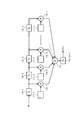
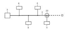
- FIG. 1 shows the first embodiment, and is an electrical configuration diagram showing an overall schematic configuration of a transmission system.
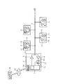
- FIG. 2 is a block diagram of an echo canceller.
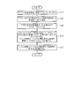
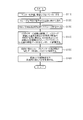
- FIG. 3 is a flowchart of the deterioration determination control.
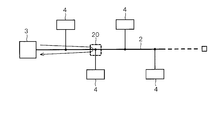
- FIG. 4 is a diagram for explaining a degradation place in the transmission system.
- FIG. 5 is a diagram illustrating an example of changes in the filter coefficients c (1) to c (n).
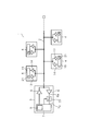
- FIG. 6 shows the second embodiment, and is an electrical configuration diagram showing an overall schematic configuration of the transmission system.
- FIG. 7 is a flowchart of the deterioration determination control.
- FIG. 1 shows the first embodiment, and is an electrical configuration diagram showing an overall schematic configuration of a transmission system.
- FIG. 2 is a block diagram of an echo canceller.
- FIG. 3 is a flowchart of the deterioration determination control.
- FIG. 4 is a diagram for explaining a degradation place in the transmission system.
- FIG. 5 is a diagram illustrating an example of changes
- FIG. 8 is a diagram for explaining a degradation place in the transmission system.
- FIG. 9 is a diagram illustrating an example of changes in the filter coefficients a (1) to a (n).
- FIG. 10 shows the third embodiment, and is an electrical configuration diagram showing an overall schematic configuration of the transmission system.
- FIG. 11 is a flowchart of the deterioration determination control.
- FIG. 12 shows a fourth embodiment and is a flowchart of deterioration determination control.
- the first embodiment will be described below with reference to FIGS. 1 to 5.
- the transmission system 1 is configured to be able to communicate by, for example, bus connection communication.
- a transmission path 2 that is a communication line and a plurality of communication devices 3 connected to the transmission path 2 4.
- the master communication device 3 has a transmission function and a reception function, and includes a driver circuit 5, a receiver circuit 6, a master control circuit 7, and an echo canceller 8.
- the driver circuit 5 receives a transmission data signal (that is, a digital signal) from the master control circuit 7, generates a transmission signal (that is, an analog pulse signal), and outputs the generated transmission signal to the transmission path 2.
- the driver circuit 5 includes a transmission-side analog circuit and a DAC (Digital Analog Converter) circuit.
- the receiver circuit 6 receives a voltage signal (that is, an analog pulse signal) from the transmission line 2, generates a reception signal (that is, a digital signal), and outputs the generated reception signal to the master control circuit 7.
- the receiver circuit 6 includes a reception-side analog circuit and an ADC (Analog Digital Converter) circuit.
- the master control circuit 7 has a function of transmitting a transmission data signal to the driver circuit 5 and receiving a reception signal from the receiver circuit 6.
- the master control circuit 7 has a function as a deterioration detection unit. When the reception signal received from the receiver circuit 6 is distorted, the master control circuit 7 has a function of correcting the distorted reception signal.
- the master control circuit 7 includes a signal generator 9 that generates, for example, a PRBS7 signal, which is a kind of pseudorandom signal, as a pseudo communication signal.
- the signal generator 9 has a function as a signal generator.
- the master control circuit 7 outputs the PRBS7 signal generated by the signal generator 9 to the transmission line 2 through the driver circuit 5 as a transmission signal.
- the echo canceller 8 has a function of canceling an echo of a transmission signal (that is, a PRBS7 signal), that is, a reflection signal from the transmission path 2.
- the echo canceller 8 has a function as a filter coefficient control circuit. The specific configuration and operation of the echo canceller 8 will be described later.
- the slave communication device 4 has a transmission function and a reception function, and includes a driver circuit 13, a receiver circuit 14, and a slave control circuit 15.
- the driver circuit 13 receives a transmission data signal (that is, a digital signal) from the slave control circuit 15 to generate a transmission signal (for example, a digital signal), and outputs the generated transmission signal to the transmission path 2.
- the receiver circuit 14 inputs a voltage signal (that is, an analog pulse signal) from the transmission line 2, digitizes the input signal using a simple determiner, and controls the slave as a received signal using the simplified digitized signal. Output to the circuit 15.
- the slave control circuit 15 has a function of transmitting a transmission data signal to the driver circuit 13 and receiving a reception signal from the receiver circuit 14. Unlike the master communication device 3, the slave communication device 4 does not include a processing circuit that corrects distortion of the received signal and a circuit that cancels echo of the transmission signal. That is, the slave communication device 4 is called a slave because it operates more passively than the master communication device 3.
- the echo canceller 8 automatically adjusts the filter coefficient so that when the transmission signal (that is, PRBS7 signal) is output from the master control circuit 7 to the transmission line 2 via the driver circuit 5, the reflection is reflected on the transmission line 2.
- the transmission signal that is, PRBS7 signal
- the signal returning to the master communication device 3, that is, the signal input to the reception terminal 7a of the master control circuit 7 can be controlled to be zero.
- the echo canceller 8 makes a copy of the echo by an internal circuit and subtracts it from the reflected signal, thereby controlling the signal input to the receiving terminal 7a of the master control circuit 7 to be zero.
- the formula for how to make a copy of Echo is:
- Echo (copy) c (1) x x (1) + c (2) x x (2) + ... + c (n) x x (n) (1)
- c (n) is a filter coefficient of the echo canceller
- x (n) is a PRBS7 signal as a transmission signal (that is, origin of echo) transmitted from the master communication device 3.
- Delay circuits 16-1 to 16-n and 16- (n + 1) are circuits that delay the input signal for a set time.
- the filter coefficient control circuits 17-1 to 17-n have a function of automatically adjusting the filter coefficients c (1) to c (n) so that the signal input to the reception terminal 7a of the master control circuit 7 becomes zero.
- the adjusted filter coefficients c (1) to c (n) are output.
- the multipliers 18-1 to 18-n calculate the multiplication part in the above equation (1).
- the adder 19 calculates the addition part in the above equation (1).
- As an algorithm for adjusting the filter coefficient for example, LMS (Least Mean Square) is preferably used, and other algorithms may be used.
- the specific value of n is preferably set according to the situation of the transmission path 2.
- the filter coefficients c (1) to c (n) of the echo canceller 8 are data corresponding to the magnitude of the signal that is reflected back (ie, echo).
- the data corresponds to the transmission characteristics. Therefore, the deterioration of the transmission path 2 can be determined by examining the change in the magnitude of each value of the filter coefficients c (1) to c (n).
- the master control circuit 7 acquires the filter coefficients c (1) to c (n) from the echo canceller 8 before deterioration of the transmission path 2 (for example, at the time of factory shipment or at the initial stage of operation), It is stored in an internal memory (for example, EEPROM or flash memory). Then, when the echo canceller 8 operates and controls so that the signal input to the reception terminal 7a of the master control circuit 7 becomes zero, the master control circuit 7 performs filter coefficients c (1) to c (1) to Acquire c (n) from the echo canceller 8 and compare the acquired filter coefficients c (1) to c (n) with the pre-degradation filter coefficients c (1) to c (n) stored in the memory.
- an internal memory for example, EEPROM or flash memory
- the process of operating the echo canceller 8 is mainly executed in a statup process until the main communication can be performed. Further, it is preferable that the processing for operating the echo canceller 8 is executed periodically (for example, once a day, once a week, etc.).
- the flowchart of FIG. 3 shows the content of the control for determining the deterioration of the transmission path 2 in the control of the master control circuit 7 of the master communication device 3.
- the master control circuit 7 transmits a control signal for stopping transmission and reception to all slave communication devices 4, and does not transmit or receive all slave communication devices 4. Enter mode.
- the process proceeds to step S20, and the master control circuit 7 transmits (ie, outputs) the PRBS7 signal to the transmission path 2 via the driver circuit 5.
- step S30 A part of the PRBS7 signal is reflected by the transmission line 2, the reflected wave (ie, echo signal) returns to the master communication device 3, and the returned reflected wave is received by the receiver circuit 6. Is received by the master control circuit 7.
- the master control circuit 7 controls the filter coefficients c (1) to c (n) of the filter coefficient control circuits 17-1 to 17-n of the echo canceller 8 to copy the echo signal. The echo is canceled by subtracting from the echo signal (ie, the reflected signal). In this case, control is performed so that the signal input to the receiving terminal 7a of the master control circuit 7 becomes zero. Since the filter coefficients c (1) to c (n) are characteristic data indicating the characteristics of the current transmission line 2, these filter coefficients c (1) to c (n) are stored in the master control circuit 7. Store in the memory.
- the filter coefficients c (1) to c (n) greatly changes in the increasing direction as shown in the table of FIG. Accordingly, when a large change as shown in the table of FIG. 5 is detected, the master control circuit 7 determines that the transmission path 2 has deteriorated. When the deterioration of the transmission path 2 is determined, the master control circuit 7 is configured to notify the user of a message indicating that the transmission path 2 has deteriorated. Thereby, the control shown in FIG. 3 is completed.
- the filter coefficients c (1) to c (n) greatly change is considered to be that impedance mismatching deteriorates due to deterioration of the transmission path 2 or disconnection.
- the control shown in FIG. 3 is configured to be executed in a statup process or periodically.
- the filter coefficient of the echo canceller 8 before deterioration (for example, at the time of shipment) is stored by the master control circuit 7, and when the echo canceller 8 operates thereafter, the echo canceller 8 filter coefficients are stored, and both filter coefficients are compared to determine whether or not the transmission path 2 has deteriorated.
- this configuration it is possible to detect deterioration of the transmission line 2 before the transmission line 2 breaks down, and it is possible to eliminate the need for a dedicated inspection device.
- since only the function of detecting the deterioration of the transmission line 2 is incorporated in the master control circuit 7 of the master communication device 3, an increase in manufacturing cost can be suppressed.
- the echo canceller 8 is periodically operated to update and store the filter coefficient, it is possible to grasp the deterioration process before the transmission line 2 is disconnected. Become. And according to the said structure, the disconnection of the transmission line 2, the connection failure of a connector, etc. are detectable by the change of the filter coefficient of the echo canceller 8. FIG.
- (Second Embodiment) 6 to 9 show a second embodiment.
- symbol is attached
- the signal generator 21 for generating the PRBS7 signal is provided in each of the slave control circuits 15 of the plurality of slave communication devices 4.
- an equalizer 22 is provided between the output terminal 6 a of the receiver circuit 6 and the input terminal 7 a of the master control circuit 7.
- the equalizer 22 has a function of correcting the distorted reception signal when the reception signal received by the receiver circuit 6 is distorted.
- the equalizer 22 has a function as a filter coefficient control circuit.
- a known PRBS7 signal is transmitted from any one slave communication device 4, and a distorted signal is received by the master communication device 3 through the transmission path 2, and this received signal is In the communication device 3, the equalizer 22 is entered via the receiver circuit 6. Since the equalizer 22 grasps the identity of the received PRBS7 signal, that is, the original waveform of the PRBS7 signal when transmitted from the slave communication device 4, the equalizer 22 adjusts the filter coefficient of the equalizer. Thus, it is possible to control so as to generate a PRBS7 signal having a substantially original waveform based on the received PRBS7 signal.
- the method for generating the PRBS7 signal is represented by the following equation.
- PRBS7 a (1) ⁇ i (1) + a (2) ⁇ i (2) + ... + a (n) ⁇ i (n) (2)
- a (n) is a filter coefficient of the equalizer
- i (n) is a received signal of the master communication device 3.
- the specific circuit of the equalizer 22 for calculating the above equation (2) that is, for generating the PRBS7 signal, has substantially the same circuit configuration as the specific circuit of the echo canceller 8 shown in FIG. It can be formed by a control circuit, a multiplier and an adder.
- the filter coefficients a (1) to a (n) of the equalizer 22 are automatically adjusted so that the signal input to the reception terminal 7a of the master control circuit 7 becomes the PRBS7 signal having the original waveform. 22 outputs the adjusted filter coefficients a (1) to a (n) to the master control circuit 7.
- the filter coefficients a (1) to a (n) of the equalizer 22 are data corresponding to the magnitude of the distortion of the signal entering the master communication device 3, and therefore the slave communication device. 4 and data corresponding to the transmission characteristics of the transmission path 2 between the master communication device 3. Therefore, the deterioration of the transmission path 2 between the slave communication device 4 and the master communication device 3 is determined by examining changes in the values of the filter coefficients a (1) to a (n). Can do.
- the master control circuit 7 uses the filter coefficient a () before the deterioration of the transmission path 2 between the slave communication device 4 and the master communication device 3 (for example, at the time of factory shipment or at the initial operation) 1) to a (n) are acquired from the equalizer 22 and stored in an internal memory (for example, an EEPROM or a flash memory).
- an internal memory for example, an EEPROM or a flash memory.
- the equalizer 22 compares the latest filter coefficients a (1) to a (n) stored in the memory with the pre-degradation filter coefficients a (1) to a (n) stored in the memory. Thus, it is possible to determine deterioration or failure of the transmission path 2 between the slave communication apparatus 4 and the master communication apparatus 3.
- the remaining slave communication devices 4 also transmit known PRBS7 signals to the transmission path 2, and transmit the transmission path 2 between the remaining slave communication devices 4 and the master communication device 3.
- the master communication device 3 receives the distorted signal, and the master communication device 3 adjusts the filter coefficient of the equalizer 22 in the master communication device 3 so that the waveform of the original waveform is substantially based on the received PRBS7 signal.
- Control for generating the PRBS7 signal is executed, and the filter coefficients a (1) to a (n) at that time are stored in the memory of the master control circuit 7.
- the master control circuit 7 then updates the latest filter coefficients a (1) to a (n) stored in the memory for each transmission path 2 between the remaining slave communication devices 4 and the master communication device 3.
- the deterioration of the transmission path 2 is determined by comparing with the pre-degradation filter coefficients a (1) to a (n) stored in the memory.
- the processing for operating the equalizer 22 is mainly executed in a stat-up process until the main communication is possible. Further, it is preferable that the process for operating the equalizer 22 is performed periodically (for example, once a day, once a week, etc.).
- the echo canceller 8 described in the first embodiment is provided inside the master communication device 3 so that echo cancellation processing is executed.
- the equalizer 22 according to the second embodiment is provided inside the master communication device 3 according to the first embodiment, and the signal generator according to the second embodiment. 21 is provided in the slave control circuit 15 of the slave communication device 4 of the first embodiment, and a process for correcting the distortion of the received signal is executed.
- step S110 the master control circuit 7 of the master communication device 3 is set to an operation mode in which the master communication device 3 is not transmitting and receiving. Subsequently, the process proceeds to step S120, and the master control circuit 7 transmits, for example, a control signal instructing to transmit the PRBS7 signal to the first (that is, the upper left in FIG. 6) slave communication device 4. The first slave communication device 4 transmits the PRBS7 signal to the transmission line 2 via the driver circuit 13.
- step S140 in the master communication device 3, the equalizer 22 controls the filter coefficients a (1) to a (n), and applies to the reception terminal 7a of the master control circuit 7 according to the equation (2).
- the input signal is adjusted to be the PRBS7 signal having the original waveform.
- the adjusted filter coefficients a (1) to a (n) become characteristic data indicating the characteristics of the transmission path 2 between the first slave communication device 4 and the master communication device 3 at the present time. From these, the filter coefficients a (1) to a (n) are stored in the memory in the master control circuit 7.
- step S150 the master control circuit 7 also applies the first slave communication device 4 to the remaining slave communication devices 4, for example, in order from the second (lower left in FIG. 6) slave communication device 4.
- Processing executed for the slave communication device 4, specifically, processing for transmitting the PRBS7 signal and operating the equalizer 22 to acquire the filter coefficients a (1) to a (n) and store them in the memory (ie, Steps S120 to S140) are executed.
- the filter coefficients a (1) to a (n) indicating the characteristics of each transmission line 2 between the second, third,... Slave communication device 4 and the master communication device 3 are obtained. And stored in the memory in the master control circuit 7.
- step S160 the master control circuit 7 determines the first, second,... Slave communication devices 4 at the present time based on the change over time of the filter coefficients a (1) to a (n).
- the deterioration or failure of each transmission line 2 between the communication device 3 and the master communication device 3 is determined. Specifically, for each transmission path 2 between the first, second,... Slave communication device 4 and the master communication device 3, before the deterioration stored in the memory, for example, at the time of shipment from the factory.
- the filter coefficients a (1) to a (n) with the latest filter coefficients a (1) to a (n) stored in the memory, the current first, second, ... slaves
- the deterioration of each transmission line 2 between the communication device 4 and the master communication device 3 is determined.
- the current slave of the fourth slave The coefficients a (1) and a (2) in the filter coefficients a (1) to a (n) indicating the characteristics of the transmission line 2 between the communication device 4 and the master communication device 3 are shown in the table of FIG. As shown in the figure, the direction of the increase greatly changes. Therefore, when a large change as shown in the table of FIG. 9 is detected, the master control circuit 7 determines that the transmission path 2 between the fourth slave communication device 4 and the master communication device 3 has deteriorated. It comes to judge.
- the master control circuit 7 When it is determined that the transmission path 2 has deteriorated, the master control circuit 7 is configured to notify the user of a message indicating that the transmission path 2 has deteriorated. In this case, the filter coefficients a (1) to a (n) indicating the characteristics of the transmission paths 2 between the slave communication devices 4 other than the fourth and the master communication device 3 are not significantly changed. Therefore, the master control circuit 7 does not determine that each transmission line 2 has deteriorated. Thereby, the control shown in FIG. 7 ends.
- the filter coefficients a (1) to a (n) largely change is considered to be that impedance mismatching deteriorates due to degradation of the transmission path 2, disconnection, or the like. Further, the control shown in FIG. 7 is configured to be executed in a statup process or periodically.
- the configuration of the second embodiment other than that described above is the same as the configuration of the first embodiment. Therefore, in the second embodiment, substantially the same operational effects as in the first embodiment can be obtained.
- (Third embodiment) 10 and 11 show a third embodiment.
- symbol is attached
- the communication unit 24 is provided in the master communication device 3 so that the master control circuit 7 can communicate with the management device 26 in the management center via the communication unit 24 and the communication network 25.
- the communication network 25 is composed of, for example, a mobile phone network or the Internet.
- the management device 26 is configured by a computer such as a server, for example.
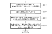
- FIG. 11 shows a flowchart of deterioration detection control of the third embodiment.
- the processing from step S110 to step S150 in FIG. 7 of the second embodiment is executed. Thereafter, the process proceeds to step S210 in FIG. 11, and the master control circuit 7 of the master communication device 3 executes the processes from step S110 to step S150 to update the filter updated periodically or in the startup process.
- Data of coefficients a (1) to a (n) is stored in an area for uploading to the management center in the internal memory. At this time, the update time data of the filter coefficients a (1) to a (n) is also stored in the area.
- step S220 the master control circuit 7 obtains the updated filter coefficients a (1) to a (n) and the execution time data at any time (for example, when step S210 is executed).
- the data is transmitted (that is, uploaded) to the management device 26 of the management center via the communication unit 24 and the communication network 25.
- step S230 the management device 26 in the management center receives the filter coefficients a (1) to a (n) and the execution time data transmitted from the master communication device 3, and receives the received filter coefficient a. (1) to a (n) and execution time data are stored in an internal memory (such as a hard disk). Furthermore, the management device 26 determines the status of the transmission path 2 based on the received filter coefficients a (1) to a (n) and the execution time, and a unique database for deterioration determination stored in the internal memory. That is, the degree of deterioration and failure are analyzed.
- step S240 the management device 26 can predict the replacement time of the parts according to the analysis result of the state of the transmission path 2, so that the user visits the store before the failure occurs.
- the management device 26 sends a message to the master communication device 3 via the communication network 25 to urge the user to visit the store for repair, thereby notifying the user. It is preferable to configure as described above.
- the transmission system 1 of this embodiment is mounted in a vehicle, for example, the user may visit the store instructed by the message in the vehicle.
- the configuration of the third embodiment other than that described above is the same as the configuration of the second embodiment. Therefore, in the third embodiment, substantially the same operational effects as in the second embodiment can be obtained.
- the filter coefficients a (1) to a (n) and the execution time data can be stored in a large-capacity memory of the management device 26, the filter coefficients a (1) to a (n) It is possible to periodically accumulate and store a large amount of soot and execution time data from the state before deterioration. Since the state of the transmission line 2 can be analyzed based on the large amount of stored data and a unique database for determining deterioration inside the management device 26, the state of deterioration of the transmission line 2 and the like can be more accurately determined. Analysis can be performed, and the detection accuracy of deterioration and the like can be increased.
- FIG. 12 shows a fourth embodiment.
- symbol is attached
- the fourth embodiment is configured to be applied to, for example, a transmission system mounted on a vehicle, and stores filter coefficients a (1) to a (n) and execution time data in the memory of the management device 26 of the management center. Instead, it is configured to be stored in a diagnostic memory mounted on the vehicle.
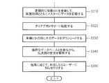
- FIG. 12 shows a flowchart of the degradation detection control of the fourth embodiment.
- the processing from step S110 to step S150 in FIG. 7 of the second embodiment is executed. Thereafter, the process proceeds to step S210 in FIG. 12, and the master control circuit 7 of the master communication device 3 executes the processes from step S110 to step S150 to update the filter updated periodically or in the startup process.
- Data of coefficients a (1) to a (n) is stored in an area for storing in a diagnosis memory in the internal memory.
- the update time data of the filter coefficients a (1) to a (n) is also stored in the area.
- step S320 the master control circuit 7 obtains the updated filter coefficients a (1) to a (n) and the execution time data at any time (for example, when step S210 is executed). It is stored (that is, transcribed) in a diagnostic memory mounted on the vehicle.
- step S330 when the user visits the vehicle by a vehicle inspection or the like, the store serviceman reads the filter coefficients a (1) to a (n) and the execution time stored in the vehicle memory. Data is read (i.e., downloaded) and stored in the memory of a store management device (e.g., a computer such as a server or terminal).
- a store management device e.g., a computer such as a server or terminal.
- step S340 the store management apparatus is based on the stored filter coefficients a (1) to a (n) and the execution time, and the original database for deterioration determination stored in the internal memory. Then, the state of the transmission path 2, that is, the degree of progress of deterioration, failure, etc. are analyzed.
- step S350 the store management device can predict the replacement time of the parts in accordance with the analysis result of the state of the transmission path 2, and therefore visits the user before the failure occurs.
- the management device is configured to display a message prompting to visit the store for repair on the display device or to notify the user by e-mail or the like when the time for parts replacement is approaching. Note that a clerk who has confirmed the message displayed on the management device may notify the user by telephone or the like.
- the configuration of the fourth embodiment other than that described above is the same as the configuration of the third embodiment. Therefore, in the fourth embodiment, substantially the same operational effects as in the third embodiment can be obtained.
- step S110 of FIG. 7 of FIG. 7 of FIG. 11 to step S150 might be performed before FIG.11 and FIG.12
- the processing from step S10 to step S40 of FIG. 3 of the first embodiment may be executed.
- filter coefficients c (1) to c (n) of the echo canceller 8 are used instead of the filter coefficients a (1) to a (n) of the equalizer 22. Also when comprised in this way, the effect similar to 3rd Embodiment and 4th Embodiment can be acquired.
- the PRBS7 signal is used as the pseudo communication signal.
- the present invention is not limited to this, and other signals may be used.
- the echo canceller 8 and the equalizer 22 are used as the filter coefficient control circuit.
- the present invention is not limited to this, and other circuits may be used.
Landscapes
- Engineering & Computer Science (AREA)
- Signal Processing (AREA)
- Computer Networks & Wireless Communication (AREA)
- Physics & Mathematics (AREA)
- General Physics & Mathematics (AREA)
- Cable Transmission Systems, Equalization Of Radio And Reduction Of Echo (AREA)
- Telephone Function (AREA)
- Testing Of Short-Circuits, Discontinuities, Leakage, Or Incorrect Line Connections (AREA)
- Tests Of Electronic Circuits (AREA)
- Dc Digital Transmission (AREA)
- Maintenance And Management Of Digital Transmission (AREA)
Priority Applications (1)
| Application Number | Priority Date | Filing Date | Title |
|---|---|---|---|
| US15/770,507 US10615846B2 (en) | 2016-01-18 | 2016-11-28 | Transmission-path degradation detection apparatus |
Applications Claiming Priority (2)
| Application Number | Priority Date | Filing Date | Title |
|---|---|---|---|
| JP2016-007112 | 2016-01-18 | ||
| JP2016007112A JP2017129378A (ja) | 2016-01-18 | 2016-01-18 | 伝送路の劣化検出装置 |
Publications (1)
| Publication Number | Publication Date |
|---|---|
| WO2017126229A1 true WO2017126229A1 (ja) | 2017-07-27 |
Family
ID=59362685
Family Applications (1)
| Application Number | Title | Priority Date | Filing Date |
|---|---|---|---|
| PCT/JP2016/085181 Ceased WO2017126229A1 (ja) | 2016-01-18 | 2016-11-28 | 伝送路の劣化検出装置 |
Country Status (3)
| Country | Link |
|---|---|
| US (1) | US10615846B2 (enExample) |
| JP (1) | JP2017129378A (enExample) |
| WO (1) | WO2017126229A1 (enExample) |
Cited By (1)
| Publication number | Priority date | Publication date | Assignee | Title |
|---|---|---|---|---|
| WO2022030192A1 (ja) * | 2020-08-04 | 2022-02-10 | 日立Astemo株式会社 | 通信装置、通信システム、通信方法 |
Families Citing this family (1)
| Publication number | Priority date | Publication date | Assignee | Title |
|---|---|---|---|---|
| US12160279B2 (en) * | 2020-11-25 | 2024-12-03 | Marvell Asia Pte Ltd | Automotive physical layer (PHY) cable fault diagnosis |
Citations (3)
| Publication number | Priority date | Publication date | Assignee | Title |
|---|---|---|---|---|
| JPS63185233A (ja) * | 1986-10-22 | 1988-07-30 | ブリティシュ・テレコミュニケーションズ・パブリック・リミテッド・カンパニ | 伝送線路障害検出方法および装置 |
| JPH04365231A (ja) * | 1991-06-12 | 1992-12-17 | Ricoh Co Ltd | 回線品質測定システム |
| JP2000235769A (ja) * | 1999-02-10 | 2000-08-29 | Hitachi Ltd | 磁気記録再生装置 |
Family Cites Families (7)
| Publication number | Priority date | Publication date | Assignee | Title |
|---|---|---|---|---|
| JP4454772B2 (ja) | 2000-03-17 | 2010-04-21 | 富士通マイクロエレクトロニクス株式会社 | 通信バスの異常検出装置とマイクロコンピュータ |
| US7295618B2 (en) * | 2004-06-16 | 2007-11-13 | International Business Machines Corporation | Automatic adaptive equalization method and system for high-speed serial transmission link |
| US8331430B2 (en) * | 2006-08-02 | 2012-12-11 | Broadcom Corporation | Channel diagnostic systems and methods |
| CN102201947B (zh) * | 2010-03-24 | 2015-08-12 | 中兴通讯股份有限公司 | 吞吐量测量方法及维护端节点 |
| JP2012149914A (ja) | 2011-01-17 | 2012-08-09 | Mitsubishi Electric Corp | プリント基板劣化検査装置および劣化検査方法 |
| US8468398B2 (en) * | 2011-01-20 | 2013-06-18 | Advanced Micro Devices, Inc. | Loopback testing with phase alignment of a sampling clock at a test receiver apparatus |
| US10222415B2 (en) * | 2016-12-12 | 2019-03-05 | Stmicroelectronics International N.V. | Generic width independent parallel checker for a device under test |
-
2016
- 2016-01-18 JP JP2016007112A patent/JP2017129378A/ja active Pending
- 2016-11-28 WO PCT/JP2016/085181 patent/WO2017126229A1/ja not_active Ceased
- 2016-11-28 US US15/770,507 patent/US10615846B2/en active Active
Patent Citations (3)
| Publication number | Priority date | Publication date | Assignee | Title |
|---|---|---|---|---|
| JPS63185233A (ja) * | 1986-10-22 | 1988-07-30 | ブリティシュ・テレコミュニケーションズ・パブリック・リミテッド・カンパニ | 伝送線路障害検出方法および装置 |
| JPH04365231A (ja) * | 1991-06-12 | 1992-12-17 | Ricoh Co Ltd | 回線品質測定システム |
| JP2000235769A (ja) * | 1999-02-10 | 2000-08-29 | Hitachi Ltd | 磁気記録再生装置 |
Cited By (3)
| Publication number | Priority date | Publication date | Assignee | Title |
|---|---|---|---|---|
| WO2022030192A1 (ja) * | 2020-08-04 | 2022-02-10 | 日立Astemo株式会社 | 通信装置、通信システム、通信方法 |
| JP2022029259A (ja) * | 2020-08-04 | 2022-02-17 | 日立Astemo株式会社 | 通信装置、通信システム、通信方法 |
| JP7417492B2 (ja) | 2020-08-04 | 2024-01-18 | 日立Astemo株式会社 | 通信装置、通信システム、通信方法 |
Also Published As
| Publication number | Publication date |
|---|---|
| US20180302122A1 (en) | 2018-10-18 |
| JP2017129378A (ja) | 2017-07-27 |
| US10615846B2 (en) | 2020-04-07 |
Similar Documents
| Publication | Publication Date | Title |
|---|---|---|
| US20130251169A1 (en) | Echo canceler and echo detector | |
| US8582443B1 (en) | Method and apparatus for virtual cable test using echo canceller coefficients | |
| US7627025B2 (en) | Echo canceller gain control for channel diagnostic systems | |
| US10454528B2 (en) | Relay device for relaying data between communication cables | |
| US20070258514A1 (en) | Apparatus for and method of far-end crosstalk (fext) detection and estimation | |
| JP5352011B2 (ja) | 温度補償用の切換え可能な基準折返し経路を用いて、ディーゼル微粒子除去装置の無線周波数伝送損失から同フィルタの負荷を求めること | |
| CN103222192A (zh) | 信号处理设备、信号处理方法和信号处理程序 | |
| JP7303459B2 (ja) | 光受信装置及び伝送特性推定方法 | |
| CN116438781B (zh) | 信号传输装置、信号传输系统和信息提供方法 | |
| JP2856113B2 (ja) | エコーキャンセラ | |
| JPWO2014128857A1 (ja) | 能動振動騒音制御装置 | |
| WO2017126229A1 (ja) | 伝送路の劣化検出装置 | |
| US20170310360A1 (en) | Echo removal device, echo removal method, and non-transitory storage medium | |
| US9641383B2 (en) | Method for error diagnosis of can communication | |
| US20160109549A1 (en) | Method for compensating for propagation inhomogeneities for a temporal reflectometry signal | |
| TWI524076B (zh) | 通道測試方法及其系統 | |
| US20230273251A1 (en) | Communication Device, Communication System, and Communication Method | |
| JP2010011265A (ja) | エコーキャンセラ装置及びその方法 | |
| US8331430B2 (en) | Channel diagnostic systems and methods | |
| JP2023040159A (ja) | 位相シフト検出装置及び位相シフト検出方法 | |
| GB2414151A (en) | Method of discriminating between double talk state and single talk state | |
| JP6230705B2 (ja) | 伝送ケーブル特性測定装置及び伝送ケーブル特性測定方法 | |
| KR0154186B1 (ko) | 능동소음제거장치의 진단장치 | |
| CN113678003A (zh) | 用于同步信号的方法 | |
| JP6435613B2 (ja) | トーク状態検出器、トーク状態検出方法、エコーキャンセラ及びエコーサプレッサ、並びに、トーク状態検出プログラム |
Legal Events
| Date | Code | Title | Description |
|---|---|---|---|
| 121 | Ep: the epo has been informed by wipo that ep was designated in this application |
Ref document number: 16886468 Country of ref document: EP Kind code of ref document: A1 |
|
| WWE | Wipo information: entry into national phase |
Ref document number: 15770507 Country of ref document: US |
|
| NENP | Non-entry into the national phase |
Ref country code: DE |
|
| 122 | Ep: pct application non-entry in european phase |
Ref document number: 16886468 Country of ref document: EP Kind code of ref document: A1 |