WO2017122592A1 - 回転打撃工具 - Google Patents
回転打撃工具 Download PDFInfo
- Publication number
- WO2017122592A1 WO2017122592A1 PCT/JP2017/000276 JP2017000276W WO2017122592A1 WO 2017122592 A1 WO2017122592 A1 WO 2017122592A1 JP 2017000276 W JP2017000276 W JP 2017000276W WO 2017122592 A1 WO2017122592 A1 WO 2017122592A1
- Authority
- WO
- WIPO (PCT)
- Prior art keywords
- motor
- rotary
- voltage supplied
- control unit
- hit
- Prior art date
Links
Images


Classifications
-
- B—PERFORMING OPERATIONS; TRANSPORTING
- B25—HAND TOOLS; PORTABLE POWER-DRIVEN TOOLS; MANIPULATORS
- B25B—TOOLS OR BENCH DEVICES NOT OTHERWISE PROVIDED FOR, FOR FASTENING, CONNECTING, DISENGAGING OR HOLDING
- B25B21/00—Portable power-driven screw or nut setting or loosening tools; Attachments for drilling apparatus serving the same purpose
- B25B21/02—Portable power-driven screw or nut setting or loosening tools; Attachments for drilling apparatus serving the same purpose with means for imparting impact to screwdriver blade or nut socket
- B25B21/023—Portable power-driven screw or nut setting or loosening tools; Attachments for drilling apparatus serving the same purpose with means for imparting impact to screwdriver blade or nut socket for imparting an axial impact, e.g. for self-tapping screws
-
- B—PERFORMING OPERATIONS; TRANSPORTING
- B25—HAND TOOLS; PORTABLE POWER-DRIVEN TOOLS; MANIPULATORS
- B25B—TOOLS OR BENCH DEVICES NOT OTHERWISE PROVIDED FOR, FOR FASTENING, CONNECTING, DISENGAGING OR HOLDING
- B25B21/00—Portable power-driven screw or nut setting or loosening tools; Attachments for drilling apparatus serving the same purpose
- B25B21/008—Portable power-driven screw or nut setting or loosening tools; Attachments for drilling apparatus serving the same purpose with automatic change-over from high speed-low torque mode to low speed-high torque mode
-
- B—PERFORMING OPERATIONS; TRANSPORTING
- B25—HAND TOOLS; PORTABLE POWER-DRIVEN TOOLS; MANIPULATORS
- B25B—TOOLS OR BENCH DEVICES NOT OTHERWISE PROVIDED FOR, FOR FASTENING, CONNECTING, DISENGAGING OR HOLDING
- B25B23/00—Details of, or accessories for, spanners, wrenches, screwdrivers
- B25B23/14—Arrangement of torque limiters or torque indicators in wrenches or screwdrivers
- B25B23/1405—Arrangement of torque limiters or torque indicators in wrenches or screwdrivers for impact wrenches or screwdrivers
-
- B—PERFORMING OPERATIONS; TRANSPORTING
- B25—HAND TOOLS; PORTABLE POWER-DRIVEN TOOLS; MANIPULATORS
- B25B—TOOLS OR BENCH DEVICES NOT OTHERWISE PROVIDED FOR, FOR FASTENING, CONNECTING, DISENGAGING OR HOLDING
- B25B23/00—Details of, or accessories for, spanners, wrenches, screwdrivers
- B25B23/14—Arrangement of torque limiters or torque indicators in wrenches or screwdrivers
- B25B23/147—Arrangement of torque limiters or torque indicators in wrenches or screwdrivers specially adapted for electrically operated wrenches or screwdrivers
- B25B23/1475—Arrangement of torque limiters or torque indicators in wrenches or screwdrivers specially adapted for electrically operated wrenches or screwdrivers for impact wrenches or screwdrivers
Definitions
- the present invention relates to a rotary impact tool, and more particularly, to a rotary impact tool that outputs intermittent rotational impact force.
- Patent Document 1 describes an impact tool that is a type of rotary impact tool and includes an impact mechanism that impacts the hammer against the anvil by reciprocating the hammer in the axial direction while rotating the hammer.
- the electric power supplied to the motor is controlled by the PWM signal (PWM control), the motor is driven in a state where the duty ratio of the PWM signal is 100%, and the current flowing through the motor is a predetermined current.
- the duty ratio is decreased to prevent excessive hammer retreat. More specifically, the duty ratio is set to 100% until the current flowing through the motor reaches a predetermined current value, and when the current flowing through the motor exceeds the predetermined current value, the duty ratio is reduced to 85%, and then continues. The duty ratio is gradually increased over multiple hits.
- Patent Document 2 describes an impact tool that is a type of rotary impact tool and includes an impact mechanism that impacts the hammer against the anvil by reciprocating in the axial direction while rotating the hammer.
- the first voltage smaller than the first voltage is applied after the first voltage is applied to the motor in a period before the hammer is hit after the minimum value of the rotational speed of the motor is detected.
- the duty ratio of PWM control is set to 100% immediately before hitting, the duty ratio is reduced to 70% from immediately before hitting to immediately after hitting, and the duty ratio is immediately set to 100% immediately after hitting. It is raised to.
- Patent Document 3 is a type of rotary impact tool, and includes an oil pulse mechanism that generates impact force by intermittently setting the oil enclosed between the liner and the shaft by rotating the liner so that the oil is intermittently in a high pressure state.
- An oil pulse tool is described.
- the driving force of the motor when the liner reverses due to a reaction immediately after hitting, the driving force of the motor is decreased, and when the liner turns forward again and passes the hitting position, the driving force of the motor is increased. By doing so, the current flowing through the motor is reduced. More specifically, the duty ratio of the PWM control is decreased from 100% to 75% immediately before the liner reaches the striking position, and a striking amount is generated when the liner reaches the striking position.
- the duty ratio is reduced to 50%.
- the duty ratio is decreased to 25%.
- the duty ratio is immediately increased to 100%.
- the oil pulse tool described in Patent Document 3 has a special structure in which the liner of the oil pulse mechanism unit is connected to the rotor of the motor without passing through the speed reduction mechanism unit. The applied torque is relatively small. Therefore, when the liner reaches the striking position, it has a characteristic that the hammer strikes for a very short time and immediately after the hammering strike, the liner immediately reverses due to the recoil of the strike. Is suitable.
- Patent Document 4 describes an electronic pulse tool that is a type of rotary impact tool and includes a pulse mechanism that strikes a hammer on an anvil by repeating forward and reverse rotations of a motor and a hammer by electronic control. .
- the duty ratio of PWM control is limited for a predetermined time and then gradually increased, thereby reducing the current flowing to the motor. . More specifically, the duty ratio of the PWM control is gradually increased until it reaches 100% while rotating the motor and hammer normally until just before hitting, and the duty ratio is set to 0% from the start of hitting to the end of hitting.
- the duty ratio is maintained at 40% for a predetermined time while reversing the motor and the hammer, and then gradually increased until reaching 100%.
- Patent Document 1 since the impact tool described in Patent Document 1 is configured to drive the motor with a duty ratio of 100%, the current flowing through the motor always increases, and the temperature rise of the motor and the switching element tends to become remarkable. there were. In addition, when the current flowing through the motor exceeds a predetermined current value, the duty ratio is uniformly reduced while a plurality of continuous rotation hits occur. However, there is a problem that the tightening performance is lowered.
- this invention aims at providing the rotary impact tool which can suppress the temperature rise of a motor or a switching element, suppressing the fall of fastening performance.
- Another object of the present invention is to provide a rotary impact tool capable of reducing a current flowing through a motor or a switching element while suppressing a decrease in tightening performance.
- Another object of the present invention is to provide a rotary impact tool with good operability.
- the present invention is provided in a motor, a tip tool holding portion driven by the motor, and a power transmission path from the motor to the tip tool holding portion.
- Rotation provided with a striking mechanism configured to intermittently generate a rotational striking force transmitted to the tip tool holding unit, a switching element for switching a voltage supplied to the motor, and a control unit for controlling the switching element It is a striking tool, and the voltage supplied to the motor starts to gradually increase between the end of the first rotational impact and the start of the second rotational impact following the first rotational impact.
- the rotary hitting tool is characterized in that the control unit is configured.
- the rotational speed of the striking mechanism immediately before the start of the rotating impact is important as one of the important factors affecting the tightening performance in the rotating impact tool. That is, in order to obtain sufficient tightening performance in the second rotational impact, it is sufficient if the rotational speed of the impact mechanism unit can be accelerated to a desired rotational speed immediately before the second rotational impact is started. Thus, it is not necessary to increase the voltage supplied to the motor immediately after the first rotational impact is finished to the maximum value.
- the rotation speed of the hitting mechanism portion refers to the relative rotation speed between the hitting portion that is the member to be hit and the hit portion that is the hit member.
- the liner portion 6A in the oil pulse unit 6 corresponds to the hitting portion
- the hitting shaft portion 6B corresponds to the hit portion
- the rotational speed of the liner portion 6A relative to the hitting shaft portion 6B is This corresponds to the rotation speed of the hitting mechanism.
- control unit gradually increases the voltage supplied to the motor from the start of the second rotary impact following the first rotary impact to the end of the second rotary impact. It is preferable to begin lowering.
- the present invention is provided in a motor, a tip tool holding portion driven by the motor, and a power transmission path from the motor to the tip tool holding portion.
- a striking mechanism configured to intermittently generate a rotational striking force transmitted to the tip tool holding unit, a switching element that switches a voltage supplied to the motor, and a control unit that controls the switching element.
- the rotary hitting tool is configured to gradually decrease the voltage supplied to the motor between the start of the second rotary hit following the first rotary hit and the end of the second rotary hit.
- a rotary impact tool is provided that is characterized by configuring the control to get started.
- the motor In order for the inventors to obtain sufficient tightening performance, it is sufficient that the motor generates a large torque only for a limited period from the start of the rotary hit to the end of the rotary hit, It has been found that the motor need not continue to generate large torque.
- the tightening is performed by configuring the control unit so that the voltage supplied to the motor starts to gradually decrease between the start of the second rotary hit and the end of the second rotary hit. The temperature rise of the motor or the switching element can be suppressed while suppressing the decrease in performance.
- control unit alternately repeats the increase period and the decrease period of the voltage supplied to the motor during a period from the end of the first rotation hit to the start of the second rotation hit. It is preferable to control the voltage supplied to the motor so that the voltage maximum value, which is a value when changing from the increase period to the decrease period, gradually increases.
- a current detection unit that detects a motor current flowing through the motor is further provided, and the control unit gradually decreases the voltage supplied to the motor when the motor current exceeds a target current value, When the motor current is less than or equal to the target current value, it is preferable to gradually increase the voltage supplied to the motor.
- the control unit controls the voltage supplied to the motor as described above and applies to the motor.
- the control is performed to reduce the voltage supplied to the motor, and then the motor is supplied to the motor while a plurality of rotational impacts occur. It is preferable to gradually increase the voltage.
- the motor current when the second operation is performed, the motor current can be lowered and the temperature increase of the motor or the switching element can be suppressed as compared with a configuration in which the voltage supplied to the motor is not once reduced. can do.
- the motor current when the second work is performed, the motor current can be increased and the tightening performance is reduced as compared with the configuration in which the tightening work is performed with the voltage supplied to the motor reduced. Can be suppressed. That is, the temperature rise of the motor or the switching element can be suppressed while suppressing the decrease in the tightening performance.
- control unit controls the voltage supplied to the motor as described above when the first work is performed by the tip tool connected to the tip tool holding unit, and the motor
- the current exceeds a determination threshold value that is larger than the target current value, it is determined that a second work in which the load applied to the motor is larger than the first work is being performed, and the second work is performed.
- the control unit decreases the voltage supplied to the motor to a first predetermined value, and then is larger than the first predetermined value from the first predetermined value.
- the voltage is increased to a second predetermined value over a predetermined period, and the voltage supplied to the motor is decreased to a third predetermined value smaller than the first predetermined value after the predetermined period has elapsed.
- the voltage supplied to the motor after a predetermined period has elapsed since the second work has been performed is reduced to a third predetermined value that is smaller than the first predetermined value.
- a large motor current does not flow, and the temperature rise of the motor or switching element can be further suppressed.
- this control part controls the voltage supplied to this motor so that the period of this rotational impact performed intermittently may become indefinite.
- the rotation hitting cycle is indefinite, the rotation hitting cycle and the mechanism used in the rotary hitting tool do not resonate. Thereby, the vibration which generate
- the present invention is further provided in a motor, a tip tool holding portion driven by the motor, and a power transmission path from the motor to the tip tool holding portion.
- a hammering mechanism configured to intermittently generate a rotary hammer transmitted to the tip tool holding unit; a switching element that switches a voltage supplied to the motor; and a controller that controls the switching element.
- the rotary impact tool wherein the control unit is configured to gradually increase a voltage supplied to the motor while a plurality of rotary impacts occur.
- the tightening performance increases as the voltage supplied to the motor increases the time of the tightening operation. Therefore, the load is small as in the case of performing the tightening operation using wood screws or the like.
- the wood screw or the like can be sufficiently fastened to the material to be fastened by merely driving the motor with a small voltage in a short time. Even if tightening is still insufficient, the voltage and tightening performance will gradually increase as work continues, so even if the load on the material to be tightened is greater than expected, it can be handled without interruption. it can. Therefore, it is possible to provide a rotary impact tool with good operability.
- the above configuration further includes a current detection unit that detects a motor current flowing through the motor, and the control unit performs control to reduce a voltage supplied to the motor when the motor current exceeds a determination threshold value. Thereafter, it is preferable that the voltage supplied to the motor is gradually increased while a plurality of rotational impacts occur.
- the motor current can be reduced and the temperature increase of the motor or the switching element can be suppressed as compared with a configuration in which the voltage supplied to the motor is not reduced.
- the motor current can be increased and a decrease in the tightening performance can be suppressed as compared with a configuration in which the tightening operation is performed with the voltage supplied to the motor reduced.
- the control unit when the motor current exceeds the determination threshold, the control unit reduces the voltage supplied to the motor to a first predetermined value, and then from the first predetermined value to the first predetermined value. It is preferable to increase over a predetermined period to a large second predetermined value, and to decrease the voltage supplied to the motor after the predetermined period has elapsed to a third predetermined value that is smaller than the first predetermined value.
- the motor current can be lowered and the temperature increase of the motor or the switching element can be suppressed as compared with a configuration in which the voltage supplied to the motor is not decreased once when the determination threshold is exceeded. Can do.
- the motor current can be increased and the decrease in tightening performance can be suppressed compared to a configuration in which tightening work is performed with the voltage supplied to the motor reduced when the discrimination threshold is exceeded. can do. That is, the temperature rise of the motor or the switching element can be suppressed while suppressing the decrease in the tightening performance.
- the voltage supplied to the motor after the predetermined period has elapsed is reduced to a third predetermined value that is smaller than the first predetermined value, a large motor current does not flow after the predetermined period has elapsed, and the motor or switching element Temperature rise can be further suppressed.
- the control unit waits between the end of the first rotation hit and the start of the second rotation hit following the first rotation hit.
- the voltage supplied to the motor starts to gradually increase, and is supplied to the motor between the start of the second rotary hit following the first rotary hit and the end of the second rotary hit. It is preferable to begin to gradually lower the applied voltage.
- the control unit is configured such that the voltage supplied to the motor starts to gradually increase between the end of the first rotary hit and the start of the second rotary hit. Therefore, it is possible to accelerate the striking mechanism while suppressing an excessive increase in current, and it is possible to suppress an increase in temperature of the motor or the switching element while suppressing a decrease in tightening performance. Furthermore, since the control unit is configured to gradually decrease the voltage supplied to the motor between the start of the second rotary hit and the end of the second rotary hit, the tightening performance The rise in the temperature of the motor or the switching element can be suppressed while suppressing the decrease.
- the control unit performs a second rotation hit following the first rotation hit after the end of the first rotation hit in the rotation hit performed intermittently.
- the voltage maximum value which is a value when the voltage supplied to the motor repeats an increase period and a decrease period alternately and shifts from the increase period to the decrease period, gradually increases until the start of It is preferable to control the voltage supplied to the motor.
- the motor current flowing through the motor also repeats the increase and decrease. For this reason, the temperature rise of a motor or a switching element can be suppressed compared with the structure to which a large motor current always flows in the state which fixed the voltage supplied to a motor to 100%.
- the voltage maximum value supplied to the motor gradually increases, a sufficient voltage is supplied to the motor, and the rotation speed of the motor (from the end of the first rotation hit to the start of the second rotation hit ( The rotational speed of the striking mechanism portion can be sufficiently increased, and a sufficient rotational striking force can be obtained.
- the control unit gradually decreases the voltage supplied to the motor.
- the motor current is less than or equal to the target current value, it is preferable to gradually increase the voltage supplied to the motor.
- this control part controls the voltage supplied to this motor so that the period of this rotational impact performed intermittently may become indefinite.
- the rotation hitting cycle is indefinite, the rotation hitting cycle and the mechanism used in the rotary hitting tool do not resonate. Thereby, the vibration which generate
- the rotary impact tool of the present invention it is possible to suppress an increase in temperature of the motor or the switching element while suppressing a decrease in tightening performance. Moreover, according to the rotary impact tool of the present invention, it is possible to suppress the current flowing through the motor or the switching element while suppressing a decrease in the tightening performance. Moreover, according to this invention, a rotary impact tool with favorable operativity can be provided.
- FIG. 2 is a partially enlarged view of FIG. 1 showing an oil pulse unit of the oil pulse driver according to the embodiment of the present invention.
- FIG. 3 is a cross-sectional view taken along the line III-III in FIG. 2 showing an oil pulse unit of an oil pulse driver according to an embodiment of the present invention, where (a) shows a case where the relative rotation angle between the liner portion and the striking shaft portion is 0 ° ) Shows the case of 180 °. It is a perspective view which shows the main shaft of the oil pulse unit in the oil pulse driver by embodiment of this invention.
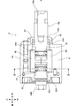
- FIG. 1 is a partial sectional side view showing an entire oil pulse driver 1 which is an example of a rotary impact tool according to an embodiment of the present invention, and shows a state where a battery pack P is mounted on the oil pulse driver 1.
- the oil pulse driver 1 is a tool that performs a tightening operation on wood screws, bolts, and the like.
- the oil pulse driver 1 includes a housing 2, a brushless motor 3, an annular substrate 4, a speed reduction mechanism 5, an oil pulse unit 6, and a control substrate unit 7.
- “front” indicated by an arrow is defined as a forward direction
- “rear” is defined as a rear direction
- “up” is defined as an upward direction
- “down” is defined as a downward direction.
- the left is defined as the left direction and the right is defined as the right direction.
- the housing 2 forms an outline of the oil pulse driver 1, and includes a motor housing portion 21, a handle portion 22, and a substrate housing portion 23.
- the motor accommodating portion 21 has a substantially cylindrical shape extending in the front-rear direction, and accommodates the brushless motor 3, the annular substrate 4, the speed reduction mechanism 5, and the oil pulse unit 6 therein. Further, a mechanism case 21 ⁇ / b> A is disposed inside the front side of the motor housing portion 21.
- the mechanism case 21A has a shape that gradually decreases in diameter toward the front, and an opening 21a is formed at the front end portion thereof.
- the brushless motor 3 is accommodated in the rear portion of the motor accommodating portion 21, and includes a rotating shaft 31, a rotor 32, and a stator 33.
- the rotating shaft 31 is a shaft extending in the front-rear direction, and is rotatably supported by the motor housing portion 21 via a bearing.
- a cooling fan 31 ⁇ / b> A is provided at the front portion of the rotating shaft 31.
- the cooling fan 31 ⁇ / b> A is a centrifugal fan, and is rotated by the rotation of the rotating shaft 31 to generate cooling air that cools the brushless motor 3, the annular substrate 4, and the like in the motor housing portion 21.
- the rotor 32 is a rotor having a plurality of permanent magnets 32 ⁇ / b> A, is fixed to the rotating shaft 31, and is configured to rotate integrally with the rotating shaft 31.
- the stator 33 is a stator having a stator winding 33 ⁇ / b> A, and is fixed to the motor housing portion 21. Details of the electrical configuration of the brushless motor 3 will be described later.
- the brushless motor 3 is an example of the “motor” in the present invention.
- the annular substrate 4 is an annular substrate in a rear view, and is disposed behind the stator 33 of the brushless motor 3. Further, an insertion hole penetrating in the front-rear direction is formed in the center of the annular substrate 4 as viewed from the rear, and the rear portion of the rotating shaft 31 is inserted through the insertion hole. Details of the electrical configuration of the annular substrate 4 will be described later.
- the reduction mechanism 5 is a planetary gear mechanism that decelerates the rotation of the rotation shaft 31 (rotor 32) of the brushless motor 3 and transmits it to the oil pulse unit 6.
- the speed reduction mechanism 5 includes a sun gear 5A that rotates integrally with the rotation shaft 31, a planetary gear 5B that meshes with the sun gear 5A, a ring gear 5C that meshes with the planetary gear 5B and is fixed to the motor housing portion 21, and a planetary gear. 5B and a carrier 5D connected to the oil pulse unit 6 and configured to rotate coaxially with the rotary shaft 31.
- the rotation of the rotating shaft 31 is converted into the orbiting motion of the planetary gear 5B via the sun gear 5A, and the orbiting motion is transmitted to the oil pulse unit 6 via the carrier 5D. Thereby, the rotation of the rotating shaft 31 is decelerated and transmitted to the oil pulse unit 6.
- the oil pulse unit 6 is a mechanism that converts the rotational force of the rotating shaft 31 (rotor 32) of the brushless motor 3 into an intermittent rotational striking force and outputs it, and is housed inside the mechanism case 21A.
- the oil pulse unit 6 includes a liner portion 6A connected to the speed reduction mechanism 5 and a striking shaft portion 6B capable of holding a tip bit (not shown).
- a tip bit In the oil pulse unit 6, by rotating the liner portion 6A with respect to the striking shaft portion 6B, intermittent rotational striking force is generated in the striking shaft portion 6B holding the tip bit.
- the oil pulse driver 1 a tightening operation for wood screws, bolts and the like is performed using the intermittent rotational impact force.
- the tip bit is a driver bit, a bolt tightening bit, or the like. Details of the oil pulse unit 6 will be described later.
- the handle portion 22 is a portion that extends downward from approximately the center in the front-rear direction of the motor housing portion 21 and is a portion that is gripped by the user.
- the handle portion 22 includes a switch trigger 22A and a switch mechanism 22B configured to be operable by a user.
- the switch trigger 22 ⁇ / b> A is provided in front of the upper end of the handle portion 22 and is connected to the switch mechanism 22 ⁇ / b> B inside the handle portion 22.
- the switch mechanism 22B is connected to the control board unit 7 and outputs a start signal to the control board unit 7 when the switch trigger 22A is pushed (turned on).
- the board housing part 23 is connected to the lower end of the handle part 22 and houses the control board part 7 therein.
- a battery connection portion 23 ⁇ / b> A configured to detachably hold the battery pack P is formed at the lower end portion of the substrate housing portion 23.
- the battery connection portion 23A has a positive connection terminal 23B and a negative connection terminal 23C (FIG. 6). Details of the electrical configuration of the control board 7 will be described later.
- the battery pack P accommodates a battery set having a secondary battery serving as a power source for the brushless motor 3, the annular substrate 4 and the control substrate unit 7.
- the battery set is configured to be connected to the plus connection terminal 23B and the minus connection terminal 23C in a state where the battery pack P is mounted (connected) to the battery connection portion 23A.
- the secondary battery is a lithium ion secondary battery.
- FIG. 2 is a partially enlarged view of FIG. 1 showing the oil pulse unit 6.
- 3 is a cross-sectional view of the oil pulse unit 6 taken along the line III-III in FIG.
- the state shown in FIG. 3A is defined as a state in which the relative rotation angle of the liner portion 6A with respect to the striking shaft portion 6B is 0 °.
- the state shown in FIG. 3B is a state in which the relative rotation angle of the liner portion 6A with respect to the striking shaft portion 6B is 180 °.
- 2 and 3 represents the rotation axis of the rotation shaft 31 (carrier 5D).
- the liner portion 6A of the oil pulse unit 6 includes a main cylindrical portion 61 having a cylindrical shape extending in the front-rear direction, a connection plate 62 for closing the rear portion of the main cylindrical portion 61, A front end cylindrical portion 63 provided at the front end of the main cylindrical portion 61, and is provided so as to be rotatable about the rotation axis A.
- a liner chamber 61a is defined inside the liner portion 6A by an inner peripheral surface of the main cylindrical portion 61, and the liner chamber. 61a is filled with oil (hydraulic oil).
- the inner peripheral surface of the main cylindrical portion 61 defines a substantially elliptical shape in the rear view, and the inner peripheral surface has a first protrusion.
- a portion 61A, a second protrusion 61B, a first protrusion 61C, and a second protrusion 61D are formed.
- the major axis of the substantially elliptic shape defined by the inner peripheral surface of the main cylindrical portion 61 is indicated by a virtual major axis XX, and the minor axis is a virtual minor axis Y-. Y is shown.
- the first convex portion 61A protrudes from the inner peripheral surface of the main cylindrical portion 61 inward in the radial direction of the main cylindrical portion 61 and extends in the front-rear direction, and is positioned on the virtual long axis XX in the rear view. is doing.
- the second convex portion 61B has the same shape as the first convex portion 61A, and is configured symmetrically with the first convex portion 61A with respect to the rotation axis A.
- the first protrusion 61C protrudes from the inner peripheral surface of the main cylindrical portion 61 inward in the radial direction of the main cylindrical portion 61 and extends in the front-rear direction, and is slightly smaller than the virtual short axis YY in the rear view. It is located on the first convex portion 61A side.
- the second protrusion 61D has the same shape as the first protrusion 61C, and is configured symmetrically with the first protrusion 61C with respect to a virtual plane that includes the virtual long axis XX and is orthogonal to the virtual short axis YY. . In the state shown in FIG.
- the first protrusion 61C and the second protrusion 61D are positioned slightly above the virtual short axis YY in the rear view, and FIG. In the state shown in (b) (relative rotation angle 180 °), it is located slightly below the virtual short axis YY.
- connection plate 62 includes a disc part 62 ⁇ / b> A and a connection part 62 ⁇ / b> B.
- the disc part 62A is a part that closes the rear part of the main cylindrical part 61, and has a circular shape in a rear view.
- a bearing hole 62a that is recessed rearward is formed in the front surface of the disc portion 62A.
- the connecting portion 62B has a substantially hexagonal shape extending in the front-rear direction, is fixed to the approximate center of the rear surface of the disc portion 62A, and is connected to the carrier 5D of the speed reduction mechanism 5 so as not to be relatively rotatable. Thereby, the liner part 6A rotates around the rotation axis A integrally with the carrier 5D.
- the distal cylindrical portion 63 is a portion that is continuous with the main cylindrical portion 61 and has a cylindrical shape that extends forward from the front end of the main cylindrical portion 61.
- the outer diameter of the distal tubular portion 63 is configured to be smaller than the outer diameter of the main tubular portion 61, and an opening 63 a is formed at the front end of the distal tubular portion 63.
- the striking shaft portion 6B of the oil pulse unit 6 includes a main shaft 64, a first blade 65, and a second blade 66.
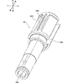
- FIG. 4 is a perspective view showing the main shaft 64.
- the main shaft 64 is a substantially cylindrical shaft extending in the front-rear direction, and the front portion thereof has an opening 63a of the liner portion 6A and an opening 21a of the mechanism case 21A (FIG. 1). ) And the rear part is accommodated in the liner chamber 61a. Further, a holding hole 64a into which the front end bit is inserted is formed in the front portion of the main shaft 64 so as to be recessed backward from the front end, and the rear end portion is inserted into the bearing hole 62a of the liner portion 6A.
- a rubber O-ring 64A is provided between the substantially central portion of the main shaft 64 in the front-rear direction and the inner peripheral surface of the tip cylindrical portion 63 of the liner portion 6A. That is, the main shaft 64 is rotatably supported by the liner portion 6A via the bearing hole 62a, and the oil inside the oil pulse unit 6 is prevented from leaking to the outside by the O-ring 64A.
- the rotation axis of the main shaft 64 substantially coincides with the rotation axis A.
- the rear portion of the main shaft 64 accommodated in the liner chamber 61a extends in the front-rear direction and passes through the center of the main shaft 64 (rotation axis A).
- a shaft through hole 64b penetrating in the radial direction is formed.
- a first seal convex portion 64B, a second seal convex portion 64C, a third seal convex portion 64D, and a first seal convex portion 64D that protrude radially outward of the main shaft 64 and extend in the front-rear direction.
- a four-seal projection 64E is formed.
- the first seal convex portion 64B is formed at a position facing the first protrusion 61C of the liner portion 6A in the state of FIG. 3A (relative rotation angle 0 °).
- the second seal convex portion 64C has the same shape as the first seal convex portion 64B, and is formed at a position facing the second protrusion 61D of the liner portion 6A in the state of FIG. In the state where the first seal convex portion 64B and the second seal convex portion 64C are opposed to the first protrusion 61C and the second protrusion 61D, a slight gap is formed between them.
- the third seal protrusion 64D is formed at a position facing the first protrusion 61C in the state shown in FIG. 3B (relative rotation angle 180 °).
- the fourth seal convex portion 64E is formed at a position facing the second protrusion 61D in the state of FIG. In the state where the third seal convex portion 64D and the fourth seal convex portion 64E are opposed to the first protrusion 61C and the second protrusion 61D, a slight gap is formed between them.
- the first blade 65 and the second blade 66 are the same member having a substantially plate shape extending in the front-rear direction, and the diameter of the main shaft 64 in the shaft through hole 64b. It is provided so that it can reciprocate in the direction.
- a spring 67 is provided between the first blade 65 and the second blade 66, and the spring 67 biases the first blade 65 and the second blade 66 outward in the radial direction of the main shaft 64. .
- the radially outer end of the first blade 65 is in contact with the first convex portion 61A of the liner portion 6A, and the radially outer end of the second blade 66 is in contact with the second convex portion 61B.
- the radially outer end of the first blade 65 is the second convex portion 61B of the liner portion 6A, and the radially outer end of the second blade 66 is the first convex portion 61A. It comes into contact.
- FIG. 5A and 5B are diagrams showing the operation of the oil pulse unit 6.
- FIG. 5A shows a case where the relative rotation angle between the liner portion 6A and the striking shaft portion 6B is 0 °
- FIG. ) Is 90 °
- (d) is 135 °
- (e) is 180 °
- (f) is 225 °
- (g) is 270 °
- (h) is 315 ° Shows the case.
- the rotation direction R (arrow) in FIG. 5 has shown the rotation direction (clockwise direction in rear view) of the liner part 6A.
- the liner portion 6A starts to rotate in the rotation direction R.
- the liner chamber 61a The liner portion 6A and the striking shaft portion 6B rotate integrally only with the resistance of the filled oil.
- the liner portion 6A and the striking shaft portion 6B do not rotate integrally, but only the liner portion 6A rotates. .
- the first protrusion 61C of the liner portion 6A is the first of the striking shaft portion 6B (main shaft 64).
- the seal protrusion 64B and the second protrusion 61D face the second seal protrusion 64C across the entire front-rear direction
- the first protrusion 61A is the first blade 65
- the second protrusion 61B is the second blade 66. Abuts over the entire front-rear direction.
- the liner chamber 61a is in a “partitioned state” that is partitioned into four chambers 61a, 61c, 61d, and 61e, as shown in FIG. 5A.
- the main cylindrical portion 61 of the liner portion 6A is provided with a torque adjustment mechanism (not shown) for adjusting the tightening torque by controlling the oil pressure that rises instantaneously.
- the first seal convex portion 64B faces the first protrusion 61C, 2
- the seal convex part 64C is facing the second protrusion 61D
- the first blade 65 is in contact with the first convex part 61A
- the second blade 66 is in contact with the second convex part 61B
- the “partition state” of the liner chamber 61a that has been partitioned into the four chambers is canceled and becomes the “partition release state”.
- the “partition release state” is entered again, and after the state of FIG. 5D (relative rotation angle 135 °), the state of FIG. Rotation angle 180 °).
- the first protrusion 61C of the liner portion 6A is the third seal protrusion 64D of the striking shaft portion 6B (main shaft 64)
- the second protrusion 61D is the front and rear of the fourth seal protrusion 64E.
- the first convex portion 61A is in contact with the second blade 66 and the second convex portion 61B is in contact with the first blade 65 over the entire front-rear direction. Accordingly, as shown in FIG.
- the liner chamber 61a is partitioned again into four chambers 61a, 61c, 61d, 61e (“partition state”), and the liner portion 6A When the ball rotates further with respect to the striking shaft portion 6B, a rotational striking force is generated again.
- the oil pulse unit 6 converts the rotational force of the rotating shaft 31 (rotor 32) of the brushless motor 3 into an intermittent rotational impact force, and outputs the intermittent rotational impact force. Tighten the bolts.
- the oil pulse unit 6 is an example of the “blow mechanism” in the present invention.
- the tip bit is an example of the “tip tool” in the present invention.
- the holding hole 64a into which the tip bit formed in the front portion of the main shaft 64 is inserted is an example of the “tip tool holding portion” in the present invention.
- FIG. 6 is a circuit diagram including a block diagram showing an electrical configuration of the oil pulse driver 1.
- the rotor 32 of the brushless motor 3 includes two sets of permanent magnets 32 ⁇ / b> A each having a north pole and a south pole.
- the stator winding 33 ⁇ / b> A of the stator 33 has star-connected three-phase coils U, V, and W, and the coils U, V, and W are connected to the annular substrate 4.
- the annular substrate 4 includes an inverter circuit 41 and three Hall ICs 42. Further, the control board unit 7 includes a control power supply circuit 71, a current detection circuit 72, a voltage detection circuit 73, a rotation position detection circuit 74, a rotation number detection circuit 75, a drive signal output circuit 76, and a control unit 77.
- the inverter circuit 41 is a circuit that supplies power from the battery pack P to the brushless motor 3, and is connected between the plus connection terminal 23 ⁇ / b> B and the minus connection terminal 23 ⁇ / b> C and the brushless motor 3.
- the inverter circuit 41 has six switching elements, that is, FETs 41A to 41F.
- the six FETs 41A to 41F are connected in a three-phase bridge form, each gate is connected to the drive signal output circuit 76, and each drain or each source is connected to the coils U, V, W of the brushless motor 3. ing.
- the six FETs 41A to 41F switch the power (voltage) supplied to the brushless motor 3.
- the six FETs 41A to 41F perform a switching operation for rotating the rotor 32 in a predetermined rotation direction based on the drive signal (gate signal) output from the drive signal output circuit 76.
- Each of the three Hall ICs 42 is provided at a position facing the rotor 32 on the front surface of the annular substrate 4, and outputs a high signal or a low signal to the rotational position detection circuit 74 according to the rotational position of the rotor 32.
- Any one of the FETs 41A to 41F is an example of the “switching element” in the present invention.
- the control power supply circuit 71 is a constant voltage power supply circuit that supplies control power to each circuit.
- the control power supply circuit 71 is configured to convert the voltage between the positive connection terminal 23B and the negative connection terminal 23C (voltage of the battery pack P) into 5V (control voltage) and apply it to each circuit. Has been.
- the current detection circuit 72 detects the current (motor current) flowing through the brushless motor 3 by taking in the voltage drop value of the shunt resistor 1A provided between the inverter circuit 41 and the minus connection terminal 23C, and detects the detected motor current. Is a circuit that outputs a signal (current value signal) corresponding to The current detection circuit 72 is an example of the “current detection unit” in the present invention.
- the voltage detection circuit 73 is connected between the plus connection terminal 23B and the minus connection terminal 23C, and is applied to the brushless motor 3 (the voltage applied between the plus connection terminal 23B and the minus connection terminal 23C). ) And outputs a signal (voltage value signal) indicating the detected voltage value to the control unit 77.
- the rotational position detection circuit 74 detects the rotational position of the rotor 32 according to a high signal or a low signal output from each of the three Hall ICs 42, and outputs a signal (rotational position signal) indicating the detected rotational position as the rotational speed. This circuit outputs the detection circuit 75 and the control unit 77.
- the rotation speed detection circuit 75 calculates the rotation speed of the rotor 32 based on the rotation position signal output from the rotation position detection circuit 74, and outputs a signal (rotation speed signal) indicating the calculated rotation speed to the control unit 77. Circuit.
- the drive signal output circuit 76 is connected to the gates of the six FETs 41A to 41F and the control unit 77.
- the drive signal output circuit 76 is a circuit that outputs drive signals to the gates of the six FETs 41A to 41F based on the control signal output from the control unit 77.
- the control unit 77 includes a processing program used for driving control of the brushless motor 3, a calculation unit (not shown) having a central processing unit (CPU) that performs calculation based on various data, the processing program, various data, various threshold values, and the like.
- a ROM (not shown) for storing, a storage unit having a RAM (not shown) for temporarily storing data, and a time measuring unit for measuring time are provided.
- the control unit 77 is a microcomputer.
- the control unit 77 Based on the rotational position signal output from the rotational position detection circuit 74, the control unit 77 forms a control signal for alternately switching the FET to be conducted among the FETs 41A to 41F, and the control signal is output to the drive signal output circuit. Output to 76.
- a predetermined coil among the coils U, V, and W is alternately energized to rotate the rotor 32 in a predetermined rotation direction.
- a drive signal for driving (conducting) the FETs 41D to 41F connected to the negative power supply side (minus line) of the inverter circuit 41 is output as a pulse width modulation signal (PWM drive signal).
- the PWM drive signal is a signal whose duty ratio can be changed.
- pulse width modulation In pulse width modulation (PWM control), the average voltage output is switched by switching the magnitude of the duty ratio, which is the pulse width. If the duty ratio is increased, the average voltage supplied (applied) to the brushless motor 3 is increased, and if the duty ratio is decreased, the average voltage supplied (applied) to the brushless motor 3 is decreased.
- the average voltage supplied to the brushless motor 3 by pulse width modulation (PWM control) is an example of the “voltage supplied to the motor” in the present invention.
- the control unit 77 is an example of the “control unit” in the present invention.
- constant current control is performed so that the motor current becomes the target current value by changing the duty ratio based on the motor current, and a predetermined current threshold value (current threshold value). If I2) is exceeded, it is determined that a fastening member such as a bolt that places an excessive load on the brushless motor 3 (liner portion 6A) at the time of seating is seated on the material to be fastened. To S110).
- the maximum value of the vertical movement centered on the target current value of the motor current when not in rotation hitting is the brushless motor 3 and the FETs 41A to 41F.
- the target current value is set so that the current value does not cause an excessive temperature increase of 41 F (so as not to reach a current value that causes an excessive temperature increase).
- the target current value is 25 A, but is not limited to this, and the motor current does not cause an excessive temperature rise in consideration of the heat resistance temperature of the motor and the switching element used. What is necessary is just to set so that it may become an electric current value.
- the duty ratio is increased or decreased by a specified amount every time the duty ratio is changed without performing control such as PID feedback control in which the gain is set high.
- the specified amount is 1%, and the duty ratio changing process by the control unit 77 is performed approximately every 1 ms. For this reason, the followability of the motor current to the target current value is slower than that of PID feedback control or the like with a high gain, and the motor current gently moves up and down around the target current value.
- the low follow-up performance with respect to the target current value compared to the PID feedback control or the like set with a high gain makes it possible to reliably determine the bolt seating while suppressing a decrease in the tightening performance. Because. More specifically, if constant current control with high follow-up to the target current value is performed, the duty ratio is suddenly reduced and tightened against the sudden increase in motor current that occurs at the time of rotational impact. Attaching performance will decrease. On the other hand, if constant current control with low followability in the present embodiment is used, it is possible to suppress a decrease in tightening performance without rapidly decreasing the duty ratio.
- the duty ratio is decreased rapidly in response to a rapid increase in motor current after the bolt is seated on the fastened material. End up. For this reason, before the motor current exceeds the current threshold value I2, the motor current is reduced to the vicinity of the target current value, and bolt seating cannot be determined (discriminated) reliably.
- the constant current control with low followability in the present embodiment the duty ratio can be reduced rapidly even with a sudden increase in motor current after the bolt is seated on the material to be fastened. There is no. For this reason, before the motor current exceeds the current threshold value I2, it is possible to reliably determine the bolt seating without reducing the motor current to near the target current value.
- the followability of constant current control is configured to be low by controlling the duty ratio to increase or decrease by a specified amount (1%) for each process of changing the duty ratio, but the present invention is not limited to this. The followability may be lowered by using PID feedback control or the like in which the gain value is appropriately set.
- FIG. 7 is a flowchart showing drive control of the brushless motor 3 by the control unit 77.
- the control unit 77 starts drive control when the battery pack P is connected to the battery connection unit 23 ⁇ / b> A and power is supplied from the control power supply circuit 71.
- the control unit 77 determines whether or not the switch trigger 22A is turned on in S101. This determination is made based on whether or not a start signal is input to the control unit 77 from the switch mechanism 22B. When the start signal is input to the control unit 77, it is determined that the switch trigger 22A is turned on.
- S101 If it is determined in S101 that the switch trigger 22A is not turned on (S101: No), the determination in S101 is performed again. That is, while the determination of S101 is repeated, the process waits until the switch trigger 22A is turned on by the user.
- a current I flowing through the brushless motor 3 (hereinafter referred to as a motor current I) is a current threshold value. It is determined whether or not I1 is exceeded.
- the controller 77 detects the motor current I based on the current value signal output from the current detection circuit 72.
- the current threshold value I1 is 25A as described above, and is a target current value in the constant current control.
- the processing duty ratio D1 which is the duty ratio in the processing of S103, is a predetermined value D (this embodiment). It is determined whether or not it is less than 100%.
- the current threshold value I2 is a threshold value for determining the type of the fastening member seated on the fastened material.
- the screw head is seated on the fastened material. If the main shaft 64 is determined to be a fastening member such as a bolt that applies an excessive load, on the other hand, if the motor current I does not exceed the current threshold I2, the main shaft 64 is also main after the screw head is seated on the material to be fastened.
- the fastening member is a fastening member such as a wood screw that is recessed into the material to be fastened.
- the current threshold I2 is an example of the “discrimination threshold” in the present invention.
- the tightening operation for the wood screw is an example of the “first operation” in the present invention.
- the tightening work before the bolt is seated in the tightening work for the bolt is an example of the “first work” in the present invention, and the tightening work after the bolt is seated in the tightening work for the bolt. Is an example of the “second operation” in the present invention.
- the duty ratio is designated in S107.
- D2 the designated duty ratio D2 is 80%.
- the value of the voltage supplied to the brushless motor 3 in the case of the designated duty ratio D2 is an example of the “first predetermined value” in the present invention.
- the duty ratio is increased to the designated value D3 (0.025% in the present embodiment) in S108, and the designated period has elapsed since the processing of S105 in S109. Determine whether or not. If it is determined in S109 that the designated period (800 ms in the present embodiment) has not elapsed, the duty ratio is increased by the designated value D3 for each process of S108 while repeating S108 and S109. In the present embodiment, the repetition cycle of S108 and S109 is 1 ms and the specified period is 800 ms. Therefore, by setting the specified value D3 to 0.025%, the duty ratio is increased during the specified period 800 ms. Increases from 80% to 100%.
- the designated period in S109 ie, 800 ms, is an example of the “predetermined period” in the present invention.
- the value of the voltage supplied to the brushless motor 3 when the duty ratio is 100% after the lapse of the designated period is the “first number” in the present invention. It is an example of “2 predetermined value”.
- the duty ratio is set to the specified duty ratio D4 (20% in the present embodiment) in S110.
- the value of the voltage supplied to the brushless motor in the case of the designated duty ratio D4 is an example of the “third predetermined value” in the present invention.
- the duty ratio becomes 20% after 800 ms has elapsed after the bolt has been seated, a large current does not flow for a long time after the bolt has been seated, and the temperature of the brushless motor 3 or FETs 41A to 41F increases. Can be suppressed. Also, since the duty ratio is once lowered to 80% and increased to 100% over 800 ms after the bolt is seated, the brushless motor 3 and The temperature rise of the FETs 41A to 41F can be further suppressed.
- the designated period of 800 ms is a period during which the bolt can be securely fastened to the material to be fastened after the bolt is seated.
- the above-mentioned numerical value is an illustration, the designation
- designated period is not restricted to 800 ms, What is necessary is just the period which can be fastened to a to-be-fastened material reliably after bolt seating.
- the designated duty ratios D2 and D3 are not limited to 80% and 0.025%, and may be any values that the duty ratio becomes 100% over a designated period from a value of 100% or less after the bolt is seated. The calculation may be performed taking into account the repetition cycle of S109.
- the duty ratio is maintained at 20% until the switch trigger 22A is turned off by the user.
- the driving of the brushless motor 3 is stopped, and the process returns to S101 and waits until the switch trigger 22A is turned on again.
- the control unit 77 stops driving the brushless motor 3, returns to S101, and the switch trigger 22A is turned on. Wait until
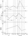
- FIG. 8 is a time chart showing the time change of the motor current, the duty ratio, and the rotation speed of the brushless motor 3, and the next rotation hit after the tightening operation is started on the wood screw and the rotation hit is performed. Indicates the period until the end of. Note that time t0 in FIG. 8 is the time when the brushless motor 3 starts driving, and time t1 is the time immediately after the rotary hitting is finished and the liner portion 6A starts to rotate relative to the hitting shaft portion 6B. .
- the motor current I changes while gently moving up and down around the current threshold value I1 (target current value) by the drive control by the control unit 77 after the end of the rotation hit.
- the motor current I flows through the brushless motor 3, the rotational speed increases.
- the next rotation hit is started at time t9, the rotation speed decreases rapidly, so that the motor current I increases rapidly.
- the duty ratio reduction processing (repetition of S102, S105, and S106) by the control unit 77 described above.
- the motor current I starts to decrease around time t12 during the rotation hitting.
- the motor current I starts to gradually decrease during the rotation hit, but the motor current I exceeds the current threshold I1 at time t13 when the rotation hit ends and the rotation speed starts increasing again, and continues to decrease after that. It starts to rise again around t15.
- the duty ratio changes while repeating the increase period and the decrease period by the drive control by the above-described control unit 77 after the end of the rotation impact.
- the voltage applied (supplied) to the brushless motor 3 changes while repeating the increase period and the decrease period after the end of the rotation impact.
- the control unit 77 repeats the above-described duty ratio reduction processing. (Repetition of S102, S105, and S106), the processing is reflected with a delay, the duty ratio starts to decrease from time t2, and continues to decrease until time t4 (period T2, decreasing period).
- the control unit 77 An increase process (repetition of S102, S103, S104) is performed, the process is reflected with a delay, the duty ratio starts increasing from time t4, and continues to increase until time t6 (period T4, increase period) .
- the duty ratio decreasing process of the control unit 77 in the period T1 is delayed and reflected from the time t2
- the duty ratio increasing process of the control unit 77 in the period T3 is reflected and delayed from the time t4. This is because a predetermined period is required from the processing until the FETs 41A to 41F of the inverter circuit 41 are driven.
- the duty ratio changes while alternately repeating the increase period and the decrease period, and the rotational impact is started at time t9, that is, the oil pulse unit at time t9.
- a rotational impact force is generated.
- the motor current I exceeds the current threshold value I1 again at time t10, and the control unit 77 starts the duty ratio reduction process again.
- the ratio is decreasing.
- the duty ratio continues to decrease after the time t13 when the rotary impact is finished, and then increases again, and the above-described process is repeated.
- the duty ratio D8 at the start of impact (time t9) is larger than the duty ratio D9 at the end of impact (time t13).
- the maximum values D5, D6, and D7 of the duty ratio when changing from the increase period to the decrease period gradually increase. That is, the maximum value D7 is larger than the maximum value D6, and the maximum value D6 is larger than the maximum value D5.
- the increase rate for example, the period T4
- the decrease rate decrease slope
- the reason why the increase rate of the motor current I due to the duty ratio increasing process becomes smaller than the decrease rate of the motor current I due to the duty ratio decreasing process is that the load applied to the brushless motor 3 decreases as the rotation speed of the brushless motor 3 increases. This is because the motor current I is unlikely to rise to the current threshold value I1. As the time taken for the motor current I to rise to the current threshold I1 becomes longer, the time for the duty ratio to rise also becomes longer. As a result, the maximum values D5, D6, and D7 of the duty ratio gradually increase. .
- the period T4 is an example of the “increase period” in the present invention
- the period T2 is an example of the “decrease period” in the present invention.
- the processing speed of the microcomputer that constitutes the control unit 77 is limited, in a series of operations in which a plurality of rotational impacts are intermittently generated, from the end of the rotational impact to the start of the next rotational impact.
- Three maximum values D5, D6, and D7 of the duty ratio are generated during the period, but when the control unit 77 is configured with a microcomputer having a higher processing speed, the duty ratio increasing process and the duty ratio decreasing process are more switched. The frequency becomes frequent, and the number of maximum values of the duty ratio that occurs between the end of the rotary hit and the start of the next rotary hit increases.
- the duty ratio is increased by a specified amount (1%) in S104.
- the specified amount may be increased as the difference between the motor current I and the current threshold I1 increases. If it is determined in S102 that the motor current I exceeds the current threshold I1, and it is determined in S105 that the motor current I does not exceed the current threshold I2, the duty ratio is set to a specified amount (1%) in S106.
- the specified amount is increased as the difference between the motor current I and the current threshold value I1 is larger in a range where the follow-up performance of the constant current control by the control unit 77 is not so high that the bolt seating cannot be determined. You may comprise so that may become large. In such a configuration, the motor current I moves up and down more finely in the vicinity of the current threshold value I1, and switching between the duty ratio increasing process and the duty ratio decreasing process becomes more frequent. Therefore, also in this case, the number of maximum values of the duty ratio that occurs between the end of the rotation hit and the start of the next rotation hit increases.
- the switching between the duty ratio increasing process and the duty ratio decreasing process becomes more frequent, and when the number of maximum duty ratios that occur between the end of the rotation hit and the start of the next rotation hit increases, Since the difference between the maximum value and the minimum value of the duty ratio becomes small, the duty ratio increases more smoothly between the end of the rotation hit and the start of the next rotation hit.
- the duty ratio gradually increases as a whole.
- the average value between the maximum value of the duty ratio and the subsequent minimum value of the duty ratio is calculated. If this average value increases with time, the duty ratio gradually increases as a whole. It can be said.
- the maximum value D5 is, for example, 90%
- the maximum value D6 is, for example, 95%
- the maximum value D7 is, for example, 100%.
- Each of the value of the voltage supplied to the brushless motor 3 in the case of the maximum value D5, the value of the voltage in the case of D6, and the value of the voltage in the case of D7 is an example of the “voltage maximum value” in the present invention.
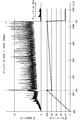
- FIG. 9 is a diagram for explaining a rotation hitting cycle when drive control is performed by the control unit 77, and shows a time change of the motor current and the number of rotations in a period corresponding to five rotation hits.
- the first rotary hit is started at time t16, the rotary hit is finished at time t17, and the second rotary hit is started at time t18. Also, a third rotary impact is started at time t19, a fourth rotary impact at time t20, and a fifth rotary impact at time t21.
- the rotation hitting interval (rotation hitting cycle) from the start of the first rotary hit (time t16) to the start of the second rotary hit (time t18) is 22 ms, and 3 from the second rotary hit (time t18).
- the rotation hitting interval until the second rotation hit (time t19) is 20 ms.
- the rotation hit interval from the third rotation hit (time t19) to the fourth rotation hit (time t20) is 26 ms, and the fifth rotation hit (time t21) from the fourth rotation hit (time t20). ) Is 21 ms.
- the rotation hits that are started from time t16, time t18, time t19, time t20, and time t21 are examples of the “first rotary hit” and the “second rotary hit” in the present invention. Assuming that the rotational impact starting from time t19 is an example of the “first rotational impact” in the present invention, the rotational impact starting from time t20 is an example of the “second rotational impact” in the present invention.
- the rotation hitting interval (rotation hitting cycle) is not constant but sparse. This is because the behavior of the motor current I and the number of rotations is slightly different for each rotation hit due to the above-described duty ratio reduction process or duty ratio increase process by the control unit 77, and the liner 6A hits after the end of the rotation hit. This is because the period until the shaft portion 6B rotates relative to the shaft portion 6B (that is, the rotation hitting interval) is different for each rotation hitting.
- FIG. 10 is a time chart showing changes over time in the motor current and the duty ratio, and shows a case where the tightening operation is performed on the bolt. Note that a time t22 in FIG. 10 is a time when the brushless motor 3 starts driving.
- the duty ratio increases from 80% to 100% over a period of 800 ms by repeating the processing of S108 to S109 of the control unit 77. During this time, the motor current I gradually increases. At time 24 when the duty ratio becomes 100% after 800 ms has elapsed from time 23, the duty ratio is reduced to 20% by the processing of S110 of the control unit 77. When the duty ratio is reduced to 20%, the motor current I is also greatly reduced.
- the oil pulse driver 1 is provided in the brushless motor 3, the main shaft 64 driven by the brushless motor 3, and the power transmission path from the brushless motor 3 to the striking shaft portion 6B.
- Controls an oil pulse unit 6 configured to intermittently generate a rotational blow that transmits the driving force of the brushless motor 3 to the main shaft 64, FETs 41A to 41F for switching the voltage supplied to the brushless motor 3, and FETs 41A to 41F.
- a control unit 77 that performs rotation hitting (for example, rotary hitting started at time t18) and the next rotary hitting (for example, rotary hitting started at time t19) following the rotary hitting. ) Gradually increases until the voltage supplied to the brushless motor 3 increases.
- Control unit 77 is configured to begin. That is, the voltage supplied to the brushless motor 3 starts to rise between the end of the rotary hit and the start of the next rotary hit following the rotary hit, and then the voltage gradually increases.
- the control unit 77 is configured.
- the power of the brushless motor 3 is transmitted in order from the brushless motor 3 through the speed reduction mechanism 5 and the oil pulse unit 6 to the tip bit, and this path is an example of the “power transmission path” in the present invention. .
- the rotational speed of the liner portion 6A with respect to the striking shaft portion 6B immediately before the start of the rotational striking is important as one of the important factors affecting the tightening performance in the rotational striking tool. .
- the rotational speed of the liner portion 6A with respect to the impact shaft portion 6B is accelerated to a desired rotational speed immediately before the second rotational impact is started. It is sufficient to be able to do this, and it is not necessary to increase the duty ratio to the maximum value immediately after the end of the rotation hit.
- control unit 77 is configured such that the voltage supplied to the brushless motor 3 starts to gradually increase between the end of the rotary hit and the start of the next rotary hit following the rotary hit.
- the liner portion 6A can be accelerated while suppressing an excessive increase in current, and the temperature increase of the brushless motor 3 or the FETs 41A to 41F can be suppressed while suppressing a decrease in fastening performance.
- control unit 77 is configured so that the voltage supplied to the brushless motor 3 starts to gradually decrease between the start of the rotary hit and the end of the rotary hit. .
- control unit 77 is configured such that the voltage supplied to the brushless motor 3 starts to decrease after the rotation hitting and ends, and thereafter the voltage gradually decreases. Has been.
- the motor In order to obtain a sufficient tightening performance, it is sufficient that the motor generates a large torque for a limited period from the start of the rotation hit to the end of the rotary hit.
- the inventors have found that it is not necessary to continue to generate a large torque. For this reason, by configuring the control unit 77 to gradually decrease the voltage supplied to the brushless motor 3 from the start of the rotary impact to the end of the rotary impact, the tightening performance is reduced. While suppressing, the temperature rise of the brushless motor 3 or the FETs 41A to 41F can be suppressed.
- the oil pulse driver 1 includes a brushless motor 3, an oil pulse unit 6 that is driven by the brushless motor 3 to intermittently perform a rotation hit, and FETs 41A to 41F that switch a voltage supplied to the brushless motor 3. And a control unit 77 that controls the FETs 41A to 41F.
- the control unit 77 is supplied to the brushless motor 3 during a period from the end of the rotary hit to the start of the next rotary hit following the rotary hit.
- the maximum value (maximum value of the duty ratio) of the voltage which is a value when the voltage (duty ratio of the PWM signal) alternately repeats the increase period and the decrease period and changes from the increase period to the decrease period, gradually increases ( The voltage (duplex) supplied to the brushless motor 3 so as to increase in the order of the maximum duty ratio D5, D6, D7). And it controls the duty ratio).
- the motor current flowing through the brushless motor 3 also repeats the increase and decrease. For this reason, the temperature increase of the brushless motor 3 or the FETs 41A to 41F is suppressed as compared with a configuration in which a large motor current always flows with the voltage supplied to the brushless motor 3 being fixed at the maximum (duty ratio is 100%). be able to. Further, since the maximum value of the voltage supplied to the brushless motor 3 gradually increases (since the maximum values D5, D6, and D7 of the duty ratio gradually increase in that order), a sufficient voltage (power) is supplied to the brushless motor 3.
- the rotational speed of the brushless motor 3 (the rotational speed of the liner portion 6A with respect to the striking shaft portion 6B) can be sufficiently increased from the end of the rotational impact to the start of the next rotational impact, so that sufficient rotation A striking force can be obtained. Accordingly, it is possible to suppress a decrease in the tightening performance while suppressing a temperature rise of the brushless motor 3 or the FETs 41D to 41F.
- the control unit 77 of the oil pulse driver 1 gradually decreases the duty ratio so that the motor current is less than or equal to the target current value (current threshold value I1). In some cases, the duty ratio is gradually increased. That is, in order to make the motor current approach the target current value, the control unit 77 does not perform constant current control with high tracking performance such as PID feedback control with a high gain, and sets the duty ratio to a fixed value every 1 ms. (1%) Control to increase or decrease is performed. For this reason, when the motor current suddenly increases at the time of the rotation impact, the duty ratio is decreased and the motor current is decreased.
- control unit 77 performs control to increase / decrease the duty ratio by 1% every 1 ms, but is not limited thereto. For example, even if the duty ratio is increased or decreased by a fixed value of 5% or less every 1 ms, the above effect can be obtained, and preferably 2% or more and 3% or less.
- the oil pulse unit 6 in the oil pulse driver 1 reduces the duty ratio to 80% when a bolt with a load applied to the brushless motor 3 larger than that of a wood screw or the like is seated on the material to be fastened. It is increased from 80% to 100% over 800 ms. For this reason, the motor current can be lowered and the temperature of the brushless motor 3 or the FETs 41A to 41F can be increased as compared with the configuration in which the tightening operation is performed with the duty ratio fixed to 100% with respect to the bolt after sitting. Can be suppressed.
- the motor current can be increased and the deterioration of the tightening performance can be suppressed as compared with the configuration in which the tightening operation is performed with the duty ratio fixed to 80% with respect to the bolt after sitting. . That is, it is possible to suppress the temperature rise of the brushless motor 3 or the FETs 41A to 41F while suppressing a decrease in tightening performance.
- control unit 77 of the oil pulse driver 1 determines that the bolt is seated on the material to be fastened when the motor current exceeds the current threshold value I2 that is larger than the target current value (current threshold value I1). ing.
- the current threshold value I2 larger than the target current value (current threshold value I1) is used to determine the seating of the bolt, it is possible to determine the seating of the bolt through which a large motor current flows during the seating.
- the control unit 77 in the oil pulse driver 1 gradually increases the duty ratio when the target current value is exceeded and gradually decreases the duty ratio when the target current value or less. Therefore, the duty ratio is not excessively decreased with respect to the motor current that rapidly increases when the bolt is seated. For this reason, it is possible to improve the accuracy of the bolt seating determination performed using the current threshold value I2 without excessively suppressing an increase in motor current accompanying the seating of the bolt.
- control unit 77 of the oil pulse driver 1 reduces the duty ratio to 20%, which is smaller than 80%, after 800 ms has elapsed since the bolt is seated. For this reason, a large motor current does not flow after 800 ms has elapsed since the bolt is seated, and the temperature rise of the brushless motor 3 or the FETs 41A to 41F can be further suppressed.
- control unit 77 of the oil pulse driver 1 controls the duty ratio so that the period of the rotational impact that is intermittently performed becomes indefinite.
- the period of a rotation impact and the mechanism etc. which are used in the rotation impact tool do not resonate.
- produces in a rotary impact tool can be reduced, and operativity can be improved.
- the rotary impact tool according to the present invention is not limited to the above-described embodiments, and various modifications can be made within the scope of the gist of the invention described in the claims.
- the oil pulse driver 1 has been described as an example.
- the present invention is not limited to this, and the present invention can be applied to an impact driver or an impact wrench having a striking mechanism portion composed of a so-called hammer and anvil. is there.
- the liner part 6A may make two rotation impacts while making one rotation with respect to the impact shaft part 6B
- it is not restricted to this.
- it is good also as a structure where one rotation hit occurs while liner 6A makes one rotation with respect to hitting shaft part 6B.
- the third seal convex portion 64D and the fourth seal convex portion 64E are deleted, it can be configured such that one rotation hit occurs while the liner portion 6A makes one rotation with respect to the hit shaft portion 6B. .
- the brushless motor 3 is adopted and the control unit 77 controls the duty ratio of pulse width modulation (PWM control).
- PWM control pulse width modulation
- the voltage supplied to the brushless motor may be switched by pulse amplitude modulation (PAM control).
- PAM control pulse amplitude modulation
- a motor provided with a brush may be employed, or the battery pack P may be replaced with an AC power source to drive the motor.
- the control unit 77 may be configured to control the conduction angle.
- the specified amount (1%) when increasing the duty ratio (S104) and the specified amount (1%) when decreasing (S106) are the same value.
- the present invention is not limited to this, and the specified amount when the duty ratio is increased (S104) may be different from the specified amount when the duty ratio is decreased (S106).
Priority Applications (4)
| Application Number | Priority Date | Filing Date | Title |
|---|---|---|---|
| US16/070,083 US10994393B2 (en) | 2016-01-14 | 2017-01-06 | Rotary impact tool |
| JP2017561600A JP6587110B2 (ja) | 2016-01-14 | 2017-01-06 | 回転打撃工具 |
| EP17738346.0A EP3406404B1 (en) | 2016-01-14 | 2017-01-06 | Rotary impact tool |
| CN201780006835.XA CN108602177B (zh) | 2016-01-14 | 2017-01-06 | 旋转冲击工具 |
Applications Claiming Priority (2)
| Application Number | Priority Date | Filing Date | Title |
|---|---|---|---|
| JP2016-004948 | 2016-01-14 | ||
| JP2016004948 | 2016-01-14 |
Publications (1)
| Publication Number | Publication Date |
|---|---|
| WO2017122592A1 true WO2017122592A1 (ja) | 2017-07-20 |
Family
ID=59311782
Family Applications (1)
| Application Number | Title | Priority Date | Filing Date |
|---|---|---|---|
| PCT/JP2017/000276 WO2017122592A1 (ja) | 2016-01-14 | 2017-01-06 | 回転打撃工具 |
Country Status (5)
| Country | Link |
|---|---|
| US (1) | US10994393B2 (zh) |
| EP (1) | EP3406404B1 (zh) |
| JP (1) | JP6587110B2 (zh) |
| CN (1) | CN108602177B (zh) |
| WO (1) | WO2017122592A1 (zh) |
Families Citing this family (9)
| Publication number | Priority date | Publication date | Assignee | Title |
|---|---|---|---|---|
| AU2019101751A4 (en) * | 2018-02-19 | 2020-11-05 | Milwaukee Electric Tool Corporation | Impact tool |
| US11597061B2 (en) * | 2018-12-10 | 2023-03-07 | Milwaukee Electric Tool Corporation | High torque impact tool |
| CN215789519U (zh) * | 2018-12-21 | 2022-02-11 | 米沃奇电动工具公司 | 冲击工具 |
| JP7386027B2 (ja) * | 2019-09-27 | 2023-11-24 | 株式会社マキタ | 回転打撃工具 |
| JP7320419B2 (ja) | 2019-09-27 | 2023-08-03 | 株式会社マキタ | 回転打撃工具 |
| JP7178591B2 (ja) * | 2019-11-15 | 2022-11-28 | パナソニックIpマネジメント株式会社 | インパクト工具、インパクト工具の制御方法及びプログラム |
| JP7281744B2 (ja) * | 2019-11-22 | 2023-05-26 | パナソニックIpマネジメント株式会社 | インパクト工具、インパクト工具の制御方法及びプログラム |
| USD948978S1 (en) | 2020-03-17 | 2022-04-19 | Milwaukee Electric Tool Corporation | Rotary impact wrench |
| JP2023075720A (ja) * | 2021-11-19 | 2023-05-31 | パナソニックホールディングス株式会社 | インパクト回転工具、インパクト回転工具システム、管理システム |
Citations (4)
| Publication number | Priority date | Publication date | Assignee | Title |
|---|---|---|---|---|
| JP2009072889A (ja) * | 2007-09-21 | 2009-04-09 | Hitachi Koki Co Ltd | インパクト工具 |
| JP2013146847A (ja) * | 2012-01-23 | 2013-08-01 | Hitachi Koki Co Ltd | インパクト工具 |
| JP2013252579A (ja) * | 2012-06-05 | 2013-12-19 | Makita Corp | 回転打撃工具 |
| JP2016078230A (ja) * | 2014-10-20 | 2016-05-16 | 株式会社マキタ | 回転打撃工具 |
Family Cites Families (22)
| Publication number | Priority date | Publication date | Assignee | Title |
|---|---|---|---|---|
| JP4289458B2 (ja) * | 2004-09-07 | 2009-07-01 | 三菱電機株式会社 | 電動パワーステアリング制御装置 |
| JP5115904B2 (ja) | 2007-09-21 | 2013-01-09 | 日立工機株式会社 | インパクト工具 |
| EP2190628B1 (en) | 2007-09-21 | 2016-03-23 | Hitachi Koki CO., LTD. | Impact tool |
| JP5126515B2 (ja) | 2008-05-08 | 2013-01-23 | 日立工機株式会社 | オイルパルス工具 |
| KR101458286B1 (ko) * | 2009-07-29 | 2014-11-04 | 히다치 고키 가부시키가이샤 | 충격 공구 |
| JP5464434B2 (ja) * | 2010-03-31 | 2014-04-09 | 日立工機株式会社 | 電動工具 |
| JP5686236B2 (ja) * | 2010-07-30 | 2015-03-18 | 日立工機株式会社 | 電動工具及びネジ締め用電動工具 |
| JP5621980B2 (ja) | 2010-12-29 | 2014-11-12 | 日立工機株式会社 | インパクト工具 |
| JP5670258B2 (ja) * | 2011-05-31 | 2015-02-18 | 日立オートモティブシステムズ株式会社 | ブラシレスモータの駆動装置 |
| JP2013022681A (ja) * | 2011-07-21 | 2013-02-04 | Hitachi Koki Co Ltd | 電動工具 |
| JP5942500B2 (ja) * | 2012-03-14 | 2016-06-29 | 日立工機株式会社 | 電動工具 |
| DE102012211910A1 (de) * | 2012-07-09 | 2014-01-09 | Robert Bosch Gmbh | Drehschlagschrauber mit einem Schlagwerk |
| WO2014084158A1 (ja) * | 2012-11-29 | 2014-06-05 | 日立工機株式会社 | インパクト工具 |
| US9272400B2 (en) * | 2012-12-12 | 2016-03-01 | Ingersoll-Rand Company | Torque-limited impact tool |
| CN104981325B (zh) * | 2013-03-30 | 2018-08-31 | 日立工机株式会社 | 电动工具 |
| JP6107385B2 (ja) * | 2013-04-26 | 2017-04-05 | 日立工機株式会社 | 電動工具 |
| CN104175267B (zh) * | 2013-05-20 | 2016-08-03 | 南京德朔实业有限公司 | 电动工具及其控制方法 |
| JP6304533B2 (ja) * | 2014-03-04 | 2018-04-04 | パナソニックIpマネジメント株式会社 | インパクト回転工具 |
| DE102014211891A1 (de) * | 2014-06-20 | 2015-12-24 | Robert Bosch Gmbh | Verfahren zum Betreiben eines Elektrowerkzeuges |
| US10322498B2 (en) * | 2014-10-20 | 2019-06-18 | Makita Corporation | Electric power tool |
| JP6390446B2 (ja) * | 2015-01-22 | 2018-09-19 | 株式会社デンソー | 回転電機の制御装置 |
| US10654153B2 (en) * | 2015-01-30 | 2020-05-19 | Koki Holdings Co., Ltd. | Impact tool |
-
2017
- 2017-01-06 JP JP2017561600A patent/JP6587110B2/ja active Active
- 2017-01-06 WO PCT/JP2017/000276 patent/WO2017122592A1/ja active Application Filing
- 2017-01-06 US US16/070,083 patent/US10994393B2/en active Active
- 2017-01-06 CN CN201780006835.XA patent/CN108602177B/zh active Active
- 2017-01-06 EP EP17738346.0A patent/EP3406404B1/en active Active
Patent Citations (4)
| Publication number | Priority date | Publication date | Assignee | Title |
|---|---|---|---|---|
| JP2009072889A (ja) * | 2007-09-21 | 2009-04-09 | Hitachi Koki Co Ltd | インパクト工具 |
| JP2013146847A (ja) * | 2012-01-23 | 2013-08-01 | Hitachi Koki Co Ltd | インパクト工具 |
| JP2013252579A (ja) * | 2012-06-05 | 2013-12-19 | Makita Corp | 回転打撃工具 |
| JP2016078230A (ja) * | 2014-10-20 | 2016-05-16 | 株式会社マキタ | 回転打撃工具 |
Non-Patent Citations (1)
| Title |
|---|
| See also references of EP3406404A4 * |
Also Published As
| Publication number | Publication date |
|---|---|
| JP6587110B2 (ja) | 2019-10-09 |
| EP3406404B1 (en) | 2021-09-01 |
| EP3406404A1 (en) | 2018-11-28 |
| US20190030692A1 (en) | 2019-01-31 |
| JPWO2017122592A1 (ja) | 2018-11-08 |
| US10994393B2 (en) | 2021-05-04 |
| CN108602177A (zh) | 2018-09-28 |
| EP3406404A4 (en) | 2019-10-02 |
| CN108602177B (zh) | 2020-08-11 |
Similar Documents
| Publication | Publication Date | Title |
|---|---|---|
| JP6587110B2 (ja) | 回転打撃工具 | |
| EP3391999B1 (en) | Rotary impact tool | |
| US10322498B2 (en) | Electric power tool | |
| US10427282B2 (en) | Rotary impact tool and method for controlling the same | |
| US11701759B2 (en) | Electric power tool | |
| EP2459348B1 (en) | Impact tool | |
| WO2013136711A2 (en) | Impact tool | |
| JP6705632B2 (ja) | 回転打撃工具 | |
| US20130062088A1 (en) | Impact tool | |
| US20130333910A1 (en) | Impact tool | |
| JP5841010B2 (ja) | 電動工具 | |
| JP2011212802A (ja) | 電動工具 | |
| WO2013183535A1 (ja) | 回転打撃工具 | |
| JP2019030947A (ja) | 電動作業機 | |
| JP5440767B2 (ja) | インパクト工具 | |
| JP5716898B2 (ja) | 電動工具 | |
| JP5516959B2 (ja) | 電動工具 | |
| US20220410352A1 (en) | Impact tool | |
| JP2011212799A (ja) | 電動工具 |
Legal Events
| Date | Code | Title | Description |
|---|---|---|---|
| 121 | Ep: the epo has been informed by wipo that ep was designated in this application |
Ref document number: 17738346 Country of ref document: EP Kind code of ref document: A1 |
|
| WWE | Wipo information: entry into national phase |
Ref document number: 2017561600 Country of ref document: JP |
|
| NENP | Non-entry into the national phase |
Ref country code: DE |
|
| WWE | Wipo information: entry into national phase |
Ref document number: 2017738346 Country of ref document: EP |
|
| ENP | Entry into the national phase |
Ref document number: 2017738346 Country of ref document: EP Effective date: 20180814 |