WO2017122490A1 - モータ制御システム - Google Patents
モータ制御システム Download PDFInfo
- Publication number
- WO2017122490A1 WO2017122490A1 PCT/JP2016/087466 JP2016087466W WO2017122490A1 WO 2017122490 A1 WO2017122490 A1 WO 2017122490A1 JP 2016087466 W JP2016087466 W JP 2016087466W WO 2017122490 A1 WO2017122490 A1 WO 2017122490A1
- Authority
- WO
- WIPO (PCT)
- Prior art keywords
- current
- phase
- value
- motor
- command value
- Prior art date
- Legal status (The legal status is an assumption and is not a legal conclusion. Google has not performed a legal analysis and makes no representation as to the accuracy of the status listed.)
- Ceased
Links
Images


Classifications
-
- H—ELECTRICITY
- H02—GENERATION; CONVERSION OR DISTRIBUTION OF ELECTRIC POWER
- H02P—CONTROL OR REGULATION OF ELECTRIC MOTORS, ELECTRIC GENERATORS OR DYNAMO-ELECTRIC CONVERTERS; CONTROLLING TRANSFORMERS, REACTORS OR CHOKE COILS
- H02P27/00—Arrangements or methods for the control of AC motors characterised by the kind of supply voltage
- H02P27/04—Arrangements or methods for the control of AC motors characterised by the kind of supply voltage using variable-frequency supply voltage, e.g. inverter or converter supply voltage
- H02P27/06—Arrangements or methods for the control of AC motors characterised by the kind of supply voltage using variable-frequency supply voltage, e.g. inverter or converter supply voltage using DC to AC converters or inverters
Definitions
- the present invention relates to a motor control system.
- Patent Document 1 Various motor control system technologies for driving an AC motor by an inverter have been proposed.
- the harmonic current component of the motor current increases as the motor speed increases. Therefore, if a motor current including a harmonic current component is used for feedback control as it is, the harmonic current component tends to be amplified in the overmodulation / rectangular wave modulation region. Therefore, there is a problem that the current control amount is saturated or fluctuates, current control in the overmodulation / rectangular wave modulation region becomes unstable, and the motor torque cannot be stably controlled.
- the present invention has been made in view of the above problems, and an object of the present invention is to provide a motor control system capable of stably controlling the torque of an AC motor by an inverter.
- the motor control system of the present invention that solves the above problem is a motor control system that drives and controls an AC motor by an inverter, calculates a voltage command value based on a target current command value, and based on the voltage command value
- a current control unit that generates a modulation wave command value of the inverter; a phase current detection unit that detects a phase current value output from the inverter to the AC motor in accordance with the modulation wave command value; the voltage command value;
- a harmonic current estimator that calculates a harmonic current component estimated value of the phase current value based on a modulated wave command value, and the current control unit calculates the phase current value and the harmonic current component estimated value.
- the target current command value is used for feedback correction.
- the torque of the AC motor can be stably controlled by the inverter.
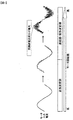
- the figure which shows the relationship between a motor rotation speed and a motor input current The figure explaining the motor control system concerning a 1st embodiment.
- FIG. 1 is a diagram showing the relationship between the motor speed and the motor input current, and shows the state of the motor input current from the sine wave modulation region to the overmodulation / rectangular wave modulation region.
- the sine wave modulation region shifts to the overmodulation / rectangular wave modulation region, and the harmonic current component included in the motor input current increases.
- the current control amount is saturated or fluctuates, current control in the overmodulation / rectangular wave modulation region becomes unstable, and the motor Torque cannot be controlled stably.
- the harmonic current component tends to be amplified instead of being suppressed.
- the harmonic current detected by the phase current detector is compared with the current command value, and a higher harmonic voltage is applied to the motor in order to reduce the current deviation.
- the harmonic component of the current is large in the overmodulation region, the current deviation is large, and voltage saturation occurs when a voltage command value exceeding the voltage value that can be actually applied is generated. As a result, a voltage for realizing the fundamental current becomes insufficient, and the harmonic current increases. By repeating this phenomenon, the harmonic current is amplified and the current control system becomes unstable.
- the present invention provides a motor control system that drives and controls the motor 4 using the inverter 3.
- the inverter output voltage which greatly affects the stability of the current control system during overmodulation.
- a harmonic current estimator that estimates the harmonic current from the harmonic voltage, and subtracting the estimated harmonic current from the motor current detected by the phase current detector, only the fundamental current of the motor current is obtained. provide feedback. Thereby, the influence of the harmonic current can be reduced even in the overmodulation / rectangular wave modulation region, and current control can be performed stably.
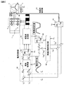
- FIG. 2 is a configuration diagram of the motor control system according to the first embodiment.
- the motor control system includes a high voltage power supply 1, a smoothing capacitor 2, an inverter 3, a motor (AC motor) 4, a rotation speed sensor 5, a phase current detector 100, a phase current detection unit 110, and a current control unit. 120, a current controller 130, a two-phase three-phase converter 140, a modulation wave generator 150, three-phase two-phase converters 160 and 170, and a harmonic current estimator 180.
- the high voltage power supply 1 is a power supply circuit for driving the system.
- the smoothing capacitor 2 is connected between the high-voltage power supply 1 and the inverter 3 to reduce voltage fluctuation.
- the inverter 3 has a DC side connected to the smoothing capacitor 2 and a three-phase AC side connected to the motor 4.
- the motor 4 is connected to the three-phase AC side of the inverter 3.
- the rotation speed sensor 5 is connected to the motor 4 and acquires the rotation speed and angle information of the motor 4.
- the phase current detector 100 is connected to the UVW phase between the three-phase AC side of the inverter 3 and the motor 4, and detects the UVW phase current output from the inverter 3 to the motor 4.
- the phase current detection unit 110 detects the phase current detected from the phase current detector 100 and inputs the phase current value to the three-phase / two-phase conversion unit 170.
- the current control unit 120 is connected to the inverter 3 and outputs a voltage calculated from the current command.
- the current control unit 120 calculates voltage commands (voltage command values) vd * and vq * based on the target current commands id and iq, and generates a modulation wave command value for the inverter 3 based on the voltage commands vd * and vq *. To do.
- the current control unit 120 includes a current controller 130, a two-phase / three-phase conversion unit 140, and a modulated wave generation unit 150 as its internal functions.
- the current controller 130 receives the deviations ⁇ id and ⁇ iq between the target current command (target current command value) id and iq and the feedback current, and calculates the voltage commands vd * and vq *.
- the current controller 130 is connected to the two-phase / three-phase converter 140 and outputs voltage commands vd * and vq *.
- the two-phase / three-phase conversion unit 140 is connected between the current controller 130 and the modulated wave generation unit 150, and the rotation speed of the motor 4 that acquires the two-phase voltage value acquired from the current controller 130 from the rotation speed sensor 5. Using ⁇ e and angle information, it is converted into a three-phase voltage value and output to the modulated wave generator 150.
- the modulated wave generator 150 is connected between the two-phase three-phase converter 140 and the inverter 3, changes the ON / OFF time ratio of the voltage value acquired from the two-phase three-phase converter 140, and is applied to the inverter 3. Adjust the average power.
- the three-phase / two-phase conversion unit 160 is connected between the modulation wave generation unit 150 and the harmonic current estimation unit 180, and the three-phase voltage acquired from the modulation wave generation unit 150 is obtained from the rotation speed sensor 5. Using the rotation speed ⁇ e and angle information, it is converted into a two-phase voltage.
- the three-phase / two-phase converter 170 is connected between the phase current detector 110 and the current controller 120, and the rotational speed ⁇ e of the motor 4 that acquires the three-phase current acquired from the phase current detector 110 from the rotational speed sensor 5. And angle information are used to convert to a two-phase current.
- the harmonic current estimation unit 180 is connected between the current control unit 120 via the three-phase / two-phase conversion unit 160 and the phase current detection unit 110 via the three-phase / two-phase conversion unit 170.
- the harmonic currents (harmonic current component estimated values) idh * and iqh * are estimated using the two-phase voltage that is the difference between the modulated wave command value and the voltage command value obtained from the above.
- the harmonic current estimation unit 180 estimates the harmonic currents idh * and iqh * using the harmonic voltages vdh * and vqh * in the output voltage of the inverter 3.
- the motor control system of this embodiment subtracts the estimated current (harmonic current idh *, iqh *) estimated by the harmonic current estimation unit 180 from the motor current (phase current value) detected by the phase current detector 100.
- the fundamental current component of the motor current is computed (fundamental current computation unit), and only the calculated fundamental current component of the motor current is fed back to the current controller 130 of the current control unit 120.
- the current control unit 120 feedback corrects the target current commands id and iq using the fed back fundamental wave current component. Specifically, deviations ⁇ id and ⁇ iq between the target current commands id and iq and the feedback current are input to the current controller 130.
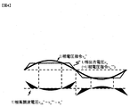
- FIG. 4 shows waveforms of the U-phase output voltage vu in the overmodulation region and the U-phase voltage command vu * generated by the modulation wave generator.
- the U-phase output voltage vu ** includes a fundamental wave component and a harmonic component, while the U-phase voltage command vu * is substantially only the fundamental wave component. Therefore, the UVW phase harmonic voltage (vuh *, vvh *, vwh *) included in the output voltage of the inverter 3 can be expressed by the following equation (1).
- the above formula (1) is the UVW phase harmonic voltage (vuh *, vvh *, vwh *) expressed in the UVW phase static coordinate system.
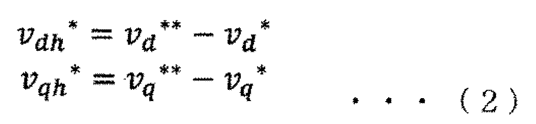
- the dq axis harmonic voltage ( vdh *, vqh *) can be expressed by the following equation (2).
- the dq-axis harmonic voltage included in the output voltage of the inverter 3 is estimated.
- dq axis voltage command (vd, vq) in the above equation (4) matches the dq axis voltage command (vd **, vq **) generated by the modulated wave generator, and the dq axis voltage command generated by the current controller.
- Vd *, vq * and dq-axis harmonic voltage (vdh *, vqh *) calculated by the harmonic current estimator. (5) is derived by converting to.
- FIG. 3 is a configuration diagram of a motor control system according to the second embodiment.
- the same components as those in the first embodiment are denoted by the same reference numerals, and detailed description thereof is omitted.
- the motor control system includes a seamless rectangular wave processing unit 200 and a PWM / rectangular wave modulator 210 instead of the modulated wave generating unit 150 of the first embodiment.
- the seamless rectangular wave processing unit 200 is connected between the two-phase three-phase converter 140 and the PWM / rectangular wave modulator 210, and the voltage acquired from the current controller 130 via the two-phase three-phase converter 140. Convert command to trapezoidal wave command value.
- the PWM / rectangular wave modulator 210 is connected between the seamless rectangular wave processing unit 200 and the inverter 3, and changes the ON / OFF time ratio of the voltage value of the trapezoidal wave command value acquired from the seamless rectangular wave processing unit 200. Thus, the average power applied to the inverter 3 is adjusted.
- FIG. 4 is a diagram illustrating the output voltage and voltage command waveforms of the motor control system according to the present embodiment.
- FIG. 4 shows waveforms of the U-phase output voltage vu and the U-phase voltage command vu * in the overmodulation region.
- the U-phase output voltage vu has the same waveform as the U-phase voltage command vu ** generated by the modulation wave generation unit 150 (seamless rectangular wave processing unit 200), and includes a fundamental wave component and a harmonic component.
- the U-phase voltage command vu * obtained from the dq-axis voltage command (vd *, vq *) generated by the current controller 130 from the two-phase / three-phase converter 140 is substantially only the fundamental wave component. Therefore, the U-phase harmonic voltage vuh * can be calculated by subtracting the U-phase voltage command vu * from the U-phase voltage command vu **.
- FIG. 5 is a diagram showing the harmonic current calculation logic of the motor control system according to the present embodiment.
- FIG. 5 shows the harmonic current calculation logic in the harmonic current estimation unit 180.
- Compensates for the interference component of the dq axis of the voltage command and can be expanded even if the motor control constant changes, and by including the rotational speed ⁇ e, which is the electric frequency of the motor, It is possible to control according to the excellent robustness.
- ⁇ e which is the electric frequency of the motor
- the load is detected by differentiating the rotational speed, and the control structure that feedback controls the torque so that the load torque and the torque command coincide with each other so that the load on the motor changes in a stepwise manner.
- the present invention is not limited to the above-described embodiments, and various designs can be made without departing from the spirit of the present invention described in the claims. It can be changed.
- the above-described embodiment has been described in detail for easy understanding of the present invention, and is not necessarily limited to one having all the configurations described.
- a part of the configuration of an embodiment can be replaced with the configuration of another embodiment, and the configuration of another embodiment can be added to the configuration of an embodiment.
Landscapes
- Engineering & Computer Science (AREA)
- Power Engineering (AREA)
- Control Of Ac Motors In General (AREA)
Abstract
インバータにより交流モータのトルクを安定に制御できるモータ制御システムを得ること。 本発明のモータ制御システムは、目標電流指令値に基づいて電圧指令値を演算し、電圧指令値に基づいてインバータ3の変調波指令値を生成する電流制御部120と、変調波指令値に応じてインバータ3から交流モータ4に出力される相電流値を検知する相電流検知部110と、電圧指令値及び変調波指令値に基づいて相電流値の高調波電流成分推定値を演算する高調波電流推定部180とを備え、電流制御部120は、相電流値と高調波電流成分推定値とを用いて目標電流指令値をフィードバック補正することを特徴とする。
Description
本発明は、モータ制御システムに関する。
インバータにより交流モータを駆動するモータ制御システムの技術が種々提案されている(特許文献1)。
モータ電流は、モータ回転数が上昇するにつれて高調波電流成分が増大する。したがって、高調波電流成分を含んだモータ電流をそのままフィードバック制御に用いると、過変調・矩形波変調領域において高調波電流成分が増幅される傾向にある。したがって、電流制御量が飽和あるいは大幅に変動し、過変調・矩形波変調領域での電流制御が不安定になり、モータのトルクを安定に制御できないという課題がある。
本発明は、上記課題に鑑みてなされたものであり、その目的とするところは、インバータにより交流モータのトルクを安定に制御できるモータ制御システムを提供することである。
上記課題を解決する本発明のモータ制御システムは、インバータにより交流モータを駆動制御するモータ制御システムであって、目標電流指令値に基づいて電圧指令値を演算し、該電圧指令値に基づいて前記インバータの変調波指令値を生成する電流制御部と、前記変調波指令値に応じて前記インバータから前記交流モータに出力される相電流値を検知する相電流検知部と、前記電圧指令値及び前記変調波指令値に基づいて前記相電流値の高調波電流成分推定値を演算する高調波電流推定部とを備え、前記電流制御部は、前記相電流値と前記高調波電流成分推定値とを用いて前記目標電流指令値をフィードバック補正することを特徴とする。
本発明によれば、インバータにより交流モータのトルクを安定に制御できる。なお、上記した以外の課題、構成及び効果は、以下の実施形態の説明により明らかにされる。
次に、本発明の実施形態について図面を用いて説明する。
図1は、モータ回転数とモータ入力電流との関係を示す図であり、正弦波変調領域から過変調・矩形波変調領域でのモータ入力電流の状態を表している。
モータ回転数は、上昇して高くなるに連れて正弦波変調領域から過変調・矩形波変調領域に移行し、モータ入力電流に含まれている高調波電流成分が増大する。このモータ入力電流の高調波電流成分を含んだモータ電流がフィードバックされると、電流制御量が飽和あるいは大幅に変動し、過変調・矩形波変調領域での電流制御が不安定になり、モータのトルクを安定に制御できない。
過変調領域における電流フィードバック系の振る舞いとして、高調波電流成分は抑制されることなく逆に増幅される傾向にある。これは以下の原理に基づく。電流フィードバック制御器では相電流検出器で検出された高調波電流は電流指令値と比較され、その電流偏差を小さくするためにより大きな高調波電圧がモータに印加される。特に、過変調領域においては電流の高調波成分が大きいため、電流偏差は大きくなり実際に印加できる電圧値を超過した電圧指令値が生じることによって電圧飽和が起こる。これにより、基本波電流を実現するための電圧が不足することになり、高調波電流が増加する。この現象が繰り返されることによって、高調波電流の増幅が起こり、電流制御系に不安定が生じる。
上記の問題点を解決するため、本発明は、インバータ3を用いてモータ4を駆動制御するモータ制御システムにおいて、過変調時の電流制御系の安定性に大きな影響を及ぼすインバータの出力電圧中の高調波電圧から高調波電流を推定する高調波電流推定部を設けて、そこで推定した高調波電流を、相電流検出器で検出したモータ電流から減算することにより、モータ電流の基本波電流のみをフィードバックする。これにより、過変調・矩形波変調領域でも高調波電流の影響を低減することができ、電流制御を安定に行うことができる。
図2は、第1実施形態に係わるモータ制御システムの構成図である。
モータ制御システムは、高圧電源1と、平滑コンデンサ2と、インバータ3と、モータ(交流モータ)4と、回転速度センサ5と、相電流検出器100と、相電流検知部110と、電流制御部120と、電流制御器130と、2相3相変換部140と、変調波生成部150と、3相2相変換部160、170と、高調波電流推定部180とを有する。
高圧電源1は、システム駆動用の電源回路である。平滑コンデンサ2は、高圧電源1とインバータ3の間に接続されており、電圧の変動を小さくする。インバータ3は、直流側が平滑コンデンサ2に接続され、3相交流側はモータ4に接続される。モータ4は、インバータ3の3相交流側に接続される。回転速度センサ5は、モータ4に接続され、モータ4の回転速度と角度情報を取得する。
相電流検出器100は、インバータ3の3相交流側とモータ4との間のUVW相に接続され、インバータ3からモータ4に出力されるUVW相電流を検出する。相電流検知部110は、相電流検出器100から検出された相電流を検知し、3相2相変換部170に相電流値を入力する。
電流制御部120は、インバータ3に接続され、電流指令から算出した電圧を出力する。電流制御部120は、目標電流指令id、iqに基づいて電圧指令(電圧指令値)vd*、vq*を演算し、電圧指令vd*、vq*に基づいてインバータ3の変調波指令値を生成する。電流制御部120は、その内部機能として、電流制御器130と、2相3相変換部140と、変調波生成部150を有している。
電流制御器130は、目標電流指令(目標電流指令値)id、iqとフィードバック電流との偏差Δid、Δiqを入力とし、電圧指令vd*,vq*を演算する。電流制御器130は、2相3相変換部140に接続されており、電圧指令vd*,vq*を出力する。
2相3相変換部140は、電流制御器130と変調波生成部150の間に接続され、電流制御器130から取得した2相の電圧値を回転速度センサ5から取得したモータ4の回転速度ωeと角度情報を用いて3相の電圧値に変換し、変調波生成部150に出力する。変調波生成部150は、2相3相変換部140とインバータ3の間に接続され、2相3相変換部140から取得した電圧値のON/OFF時間比率を変化させて、インバータ3にかかる平均電力を調整する。
3相2相変換部160は、変調波生成部150と高調波電流推定部180の間に接続され、変調波生成部150から取得した3相電圧を、回転速度センサ5から取得したモータ4の回転速度ωeと角度情報を用いて2相電圧に変換する。3相2相変換部170は、相電流検知部110と電流制御部120の間に接続され、相電流検知部110から取得した3相電流を回転速度センサ5から取得したモータ4の回転速度ωeと角度情報を用いて2相電流に変換する。
高調波電流推定部180は、3相2相変換部160を介して電流制御部120と、3相2相変換部170を介して相電流検知部110との間に接続され、電流制御部120から取得した変調波指令値と電圧指令値の差である2相電圧を用いて、高調波電流(高調波電流成分推定値)idh*,iqh*を推定する。
高調波電流推定部180は、インバータ3の出力電圧中の高調波電圧vdh*,vqh*を用いて高調波電流idh*,iqh*を推定する。本実施形態のモータ制御システムは、高調波電流推定部180で推定した推定電流(高調波電流idh*,iqh*)を、相電流検出器100で検出したモータ電流(相電流値)から減算することにより、モータ電流の基本波電流成分を演算し(基本波電流演算部)、その算出したモータ電流の基本波電流成分のみを電流制御部120の電流制御器130にフィードバックする。
電流制御部120は、フィードバックされた基本波電流成分を用いて目標電流指令id、iqをフィードバック補正する。具体的は、目標電流指令id、iqとフィードバック電流との偏差Δid、Δiqを電流制御器130に入力する。
次に、高調波電流推定部180での高調波電流推定法について詳細に説明する。過変調領域におけるU相出力電圧vuと、変調波生成器で生成したU相電圧指令vu*の波形を図4に示す。U相出力電圧vu**は、基本波成分と高調波成分を含んでおり、一方、U相電圧指令vu*は、ほぼ基本波成分のみである。よって、インバータ3の出力電圧に含まれるUVW相の高調波電圧(vuh*,vvh*,vwh*)は、以下の式(1)で表せる。

上記式(1)は、UVW相静止座標系で表したUVW相高調波電圧(vuh*,vvh*,vwh*)であり、これをdq軸回転座標系に変換すると、dq軸高調波電圧(vdh*,vqh*)は、下記の式(2)で表すことができる。
以上により、インバータ3の出力電圧中に含まれるdq軸高調波電圧を推定する。
次に、上記式(2)とモータ4の電圧方程式を用いて、dq軸高調波電圧(idh*,iqh*)の推定式を導出する。下記の式(3)に示すモータ4の電圧方程式を、dq軸電流の時間微分系に変換して整理すると、下記の式(4)が算出される。


vd:d軸電圧[V]、vq:q軸電圧[V]、R:モータ相抵抗[W]、ωe:モータ電気周波数 [rad/s],id:d軸電流[A]、iq:q軸電流[A]、Ld:d軸インダクタンス、Lq: q軸インダクタンス、ke:逆起電力定数[V/rad/s]
上記式(4)のdq軸電圧(vd,vq)は変調波生成部で生成したdq軸電圧指令(vd**,vq**)と一致し、かつ電流制御器で生成したdq軸電圧指令(vd*,vq*)と高調波電流推定部で算出したdq軸高調波電圧(vdh*,vqh*)の和で表すことができるため、式(4)を高調波成分に着目した電圧方程式に変換すると式(5)が導出される。
上記式(4)のdq軸電圧(vd,vq)は変調波生成部で生成したdq軸電圧指令(vd**,vq**)と一致し、かつ電流制御器で生成したdq軸電圧指令(vd*,vq*)と高調波電流推定部で算出したdq軸高調波電圧(vdh*,vqh*)の和で表すことができるため、式(4)を高調波成分に着目した電圧方程式に変換すると式(5)が導出される。

以上により、モータ電流に含まれるdq軸高調波電圧を推定する。
上記のようにして推定したdq軸高調波電流(idh*,iqh*)を、相電流検出器100で検出したモータ4のdq軸電流から減算することにより、モータ電流の基本波成分のみを電流制御器130にフィードバックすることができる。
図3は、第2実施形態に係わるモータ制御システムの構成図である。第1実施形態と同様の構成要素には、同一の符号を付することでその詳細な説明を省略する。
モータ制御システムは、第1実施形態の変調波生成部150の代わりに、シームレス矩形波処理部200と、PWM・矩形波変調器210を有している。シームレス矩形波処理部200は、2相3相変換部140とPWM・矩形波変調器210との間に接続されており、電流制御器130から2相3相変換部140を介して取得した電圧指令を台形波指令値に変換する。PWM・矩形波変調器210は、シームレス矩形波処理部200とインバータ3の間に接続されており、シームレス矩形波処理部200から取得した台形波指令値を電圧値のON/OFF時間比率を変化させて、インバータ3にかかる平均電力を調整する。
図4は、本実施形態にかかるモータ制御システムの出力電圧と電圧指令の波形を説明する図である。図4には、過変調領域におけるU相出力電圧vuとU相電圧指令vu*の波形が示されている。
U相出力電圧vuは、変調波生成部150(シームレス矩形波処理部200)で生成したU相電圧指令vu**と同一波形であり、基本波成分と高調波成分を含んでいる。一方、電流制御器130で生成したdq軸電圧指令(vd*,vq*)を2相3相変換部140より取得されたU相電圧指令vu*は、ほぼ基本波成分のみである。よって、U相電圧指令vu**からU相電圧指令vu*を減算することにより、U相高調波電圧vuh*を算出できる。
図5は、本実施形態にかかるモータ制御システムの高調波電流計算ロジックを示す図である。図5には、高調波電流推定部180での高調波電流計算ロジックが示されている。
電圧指令のdq軸の干渉成分を補償しており、モータ制御定数が変化しても式展開が可能であり、またモータの電気周波数である回転速度ωeが含まれることにより、モータの実速度に応じた制御が可能となりロバスト性に優れている。すなわち、モータ制御システムが過変調となる運転状態において、負荷変動によってモータの速度が変動した場合にも回転速度を用いた高応答な電流制御を実現できるため、モータ停止状態から高速回転状態まで安定したモータ制御システムを提供できる利点がある。更に、回転速度を微分して負荷トルクを検出し、負荷トルクとトルク指令とが一致するようにトルクをフィードバック制御する制御構成にすることで、モータの負荷がステップ状に変化する急激な負荷変動をする場合にも安定した高応答なトルク制御ができるモータ制御システムを提供できる利点がある。
以上、本発明の実施形態について詳述したが、本発明は、前記の実施形態に限定されるものではなく、特許請求の範囲に記載された本発明の精神を逸脱しない範囲で、種々の設計変更を行うことができるものである。例えば、前記した実施の形態は本発明を分かりやすく説明するために詳細に説明したものであり、必ずしも説明した全ての構成を備えるものに限定されるものではない。また、ある実施形態の構成の一部を他の実施形態の構成に置き換えることが可能であり、また、ある実施形態の構成に他の実施形態の構成を加えることも可能である。さらに、各実施形態の構成の一部について、他の構成の追加・削除・置換をすることが可能である。
1 高圧電源
2 平滑コンデンサ
3 インバータ
4 モータ(交流モータ)
5 回転速度センサ
100 相電流検出器
110 相電流検知部
120 電流制御部
130 電流制御器
140 2相3相変換部
150 変調波生成部
160 3相2相変換部
170 3相2相変換部
180 高調波電流推定部
200 シームレス矩形波処理部
210 PWM・矩形波変調器
2 平滑コンデンサ
3 インバータ
4 モータ(交流モータ)
5 回転速度センサ
100 相電流検出器
110 相電流検知部
120 電流制御部
130 電流制御器
140 2相3相変換部
150 変調波生成部
160 3相2相変換部
170 3相2相変換部
180 高調波電流推定部
200 シームレス矩形波処理部
210 PWM・矩形波変調器
Claims (6)
- インバータにより交流モータを駆動制御するモータ制御システムであって、
目標電流指令値に基づいて電圧指令値を演算し、該電圧指令値に基づいて前記インバータの変調波指令値を生成する電流制御部と、
前記変調波指令値に応じて前記インバータから前記交流モータに出力される相電流値を検知する相電流検知部と、
前記電圧指令値及び前記変調波指令値に基づいて前記相電流値の高調波電流成分推定値を演算する高調波電流推定部と、を備え、
前記電流制御部は、前記相電流値と前記高調波電流成分推定値とを用いて前記目標電流指令値をフィードバック補正することを特徴とするモータ制御システム。 - 前記相電流値と前記高調波電流成分推定値に基づいて前記相電流値の基本波電流成分を演算する基本波電流成分演算部と、を備え、
前記電流制御部は、前記基本波電流成分を用いて前記目標電流指令値をフィードバック補正することを特徴とする請求項1に記載のモータ制御システム。 - 前記高調波電流推定部は、前記インバータの出力電圧中の高調波電圧に基づき、高調波電流を推定することを特徴とする請求項1又は2に記載のモータ制御システム。
- 前記交流モータの回転速度を検出する回転速度センサを備え、
前記高調波電流推定部は、前記電圧指令値及び前記変調波指令値及び前記回転速度に基づいて前記相電流値の高調波電流成分推定値を演算することを特徴とする請求項1から請求項3のいずれか一項に記載のモータ制御システム。 - 前記電流制御部は、前記回転速度に基づいて2相の電圧値を3相の電圧値に変換することを特徴とする請求項4に記載のモータ制御システム。
- 前記電流制御部により生成された3相の電圧値を前記交流モータの回転速度に基づいて2相の電圧値に変換する3相2相変換部を有することを特徴とする請求項5に記載のモータ制御システム。
Priority Applications (1)
| Application Number | Priority Date | Filing Date | Title |
|---|---|---|---|
| JP2017561555A JPWO2017122490A1 (ja) | 2016-01-12 | 2016-12-16 | モータ制御システム |
Applications Claiming Priority (2)
| Application Number | Priority Date | Filing Date | Title |
|---|---|---|---|
| JP2016-003171 | 2016-01-12 | ||
| JP2016003171 | 2016-01-12 |
Publications (1)
| Publication Number | Publication Date |
|---|---|
| WO2017122490A1 true WO2017122490A1 (ja) | 2017-07-20 |
Family
ID=59311330
Family Applications (1)
| Application Number | Title | Priority Date | Filing Date |
|---|---|---|---|
| PCT/JP2016/087466 Ceased WO2017122490A1 (ja) | 2016-01-12 | 2016-12-16 | モータ制御システム |
Country Status (2)
| Country | Link |
|---|---|
| JP (1) | JPWO2017122490A1 (ja) |
| WO (1) | WO2017122490A1 (ja) |
Cited By (1)
| Publication number | Priority date | Publication date | Assignee | Title |
|---|---|---|---|---|
| CN113994587A (zh) * | 2019-06-26 | 2022-01-28 | 株式会社丰田自动织机 | 电动机的控制装置 |
Citations (1)
| Publication number | Priority date | Publication date | Assignee | Title |
|---|---|---|---|---|
| JP2013094031A (ja) * | 2011-10-27 | 2013-05-16 | Hitachi Automotive Systems Ltd | 車両駆動用誘導電動機の制御装置 |
-
2016
- 2016-12-16 JP JP2017561555A patent/JPWO2017122490A1/ja active Pending
- 2016-12-16 WO PCT/JP2016/087466 patent/WO2017122490A1/ja not_active Ceased
Patent Citations (1)
| Publication number | Priority date | Publication date | Assignee | Title |
|---|---|---|---|---|
| JP2013094031A (ja) * | 2011-10-27 | 2013-05-16 | Hitachi Automotive Systems Ltd | 車両駆動用誘導電動機の制御装置 |
Non-Patent Citations (1)
| Title |
|---|
| LERDUDOMSAK SMITH ET AL.: "Harmonic Currents Estimation and Compensation for Current Control System of IPMSM in Overmodulation Range", POWER CONVERSION CONFERENCE -NAGOYA, 18 June 2007 (2007-06-18), XP031178636 * |
Cited By (2)
| Publication number | Priority date | Publication date | Assignee | Title |
|---|---|---|---|---|
| CN113994587A (zh) * | 2019-06-26 | 2022-01-28 | 株式会社丰田自动织机 | 电动机的控制装置 |
| CN113994587B (zh) * | 2019-06-26 | 2023-09-01 | 株式会社丰田自动织机 | 电动机的控制装置 |
Also Published As
| Publication number | Publication date |
|---|---|
| JPWO2017122490A1 (ja) | 2018-08-30 |
Similar Documents
| Publication | Publication Date | Title |
|---|---|---|
| US9257931B2 (en) | Power conversion apparatus | |
| US8269441B2 (en) | Motor control apparatus | |
| KR101027231B1 (ko) | 영구 자석 동기 전동기의 벡터 제어 장치 | |
| TWI654827B (zh) | 換流器控制裝置及馬達驅動系統 | |
| JP5633551B2 (ja) | 交流電動機の制御装置 | |
| US11601080B2 (en) | Motor control device | |
| JP6369517B2 (ja) | 電力変換器の制御装置 | |
| JPWO2019008676A1 (ja) | インバータ装置、及び、電動パワーステアリング装置 | |
| WO2017221339A1 (ja) | 電力変換装置 | |
| CN101248576A (zh) | 功率变换装置 | |
| JP2008199709A (ja) | インバータ制御装置及び交流電動機制御装置 | |
| CN111758215B (zh) | 电动机控制方法以及电动机控制装置 | |
| JP2004289926A (ja) | モーター制御装置 | |
| JP2018523462A (ja) | モータコントローラおよびモータシステム | |
| JP2020096425A (ja) | 永久磁石同期電動機の制御装置,マイクロコンピュータ,電動機システム及び永久磁石同期電動機の運転方法 | |
| JP2009284598A (ja) | 交流電動機の制御装置 | |
| JPWO2017122490A1 (ja) | モータ制御システム | |
| JP2011217575A (ja) | 電力変換装置 | |
| WO2024190626A1 (ja) | モータ制御装置および電気車 | |
| WO2024190624A1 (ja) | モータ制御装置および電気車 | |
| JP2017143620A (ja) | 過変調pwmインバータ装置 | |
| JP5862690B2 (ja) | 電動機駆動装置の制御装置および電動機駆動システム | |
| WO2015005016A1 (ja) | インバータの制御装置及びインバータの制御方法 | |
| JP5640452B2 (ja) | 電力変換器の制御装置 | |
| KR101996838B1 (ko) | 유도 전동기 제어 시스템 |
Legal Events
| Date | Code | Title | Description |
|---|---|---|---|
| 121 | Ep: the epo has been informed by wipo that ep was designated in this application |
Ref document number: 16885092 Country of ref document: EP Kind code of ref document: A1 |
|
| ENP | Entry into the national phase |
Ref document number: 2017561555 Country of ref document: JP Kind code of ref document: A |
|
| NENP | Non-entry into the national phase |
Ref country code: DE |
|
| 122 | Ep: pct application non-entry in european phase |
Ref document number: 16885092 Country of ref document: EP Kind code of ref document: A1 |