WO2017122389A1 - 磁気粘性流体緩衝器 - Google Patents
磁気粘性流体緩衝器 Download PDFInfo
- Publication number
- WO2017122389A1 WO2017122389A1 PCT/JP2016/076679 JP2016076679W WO2017122389A1 WO 2017122389 A1 WO2017122389 A1 WO 2017122389A1 JP 2016076679 W JP2016076679 W JP 2016076679W WO 2017122389 A1 WO2017122389 A1 WO 2017122389A1
- Authority
- WO
- WIPO (PCT)
- Prior art keywords
- piston
- core
- coil
- magnetorheological fluid
- fluid chamber
- Prior art date
- Legal status (The legal status is an assumption and is not a legal conclusion. Google has not performed a legal analysis and makes no representation as to the accuracy of the status listed.)
- Ceased
Links
Images


Classifications
-
- F—MECHANICAL ENGINEERING; LIGHTING; HEATING; WEAPONS; BLASTING
- F16—ENGINEERING ELEMENTS AND UNITS; GENERAL MEASURES FOR PRODUCING AND MAINTAINING EFFECTIVE FUNCTIONING OF MACHINES OR INSTALLATIONS; THERMAL INSULATION IN GENERAL
- F16F—SPRINGS; SHOCK-ABSORBERS; MEANS FOR DAMPING VIBRATION
- F16F9/00—Springs, vibration-dampers, shock-absorbers, or similarly-constructed movement-dampers using a fluid or the equivalent as damping medium
- F16F9/32—Details
- F16F9/53—Means for adjusting damping characteristics by varying fluid viscosity, e.g. electromagnetically
- F16F9/535—Magnetorheological [MR] fluid dampers
-
- F—MECHANICAL ENGINEERING; LIGHTING; HEATING; WEAPONS; BLASTING
- F16—ENGINEERING ELEMENTS AND UNITS; GENERAL MEASURES FOR PRODUCING AND MAINTAINING EFFECTIVE FUNCTIONING OF MACHINES OR INSTALLATIONS; THERMAL INSULATION IN GENERAL
- F16F—SPRINGS; SHOCK-ABSORBERS; MEANS FOR DAMPING VIBRATION
- F16F9/00—Springs, vibration-dampers, shock-absorbers, or similarly-constructed movement-dampers using a fluid or the equivalent as damping medium
- F16F9/32—Details
- F16F9/53—Means for adjusting damping characteristics by varying fluid viscosity, e.g. electromagnetically
- F16F9/535—Magnetorheological [MR] fluid dampers
- F16F9/537—Magnetorheological [MR] fluid dampers specially adapted valves therefor
-
- F—MECHANICAL ENGINEERING; LIGHTING; HEATING; WEAPONS; BLASTING
- F16—ENGINEERING ELEMENTS AND UNITS; GENERAL MEASURES FOR PRODUCING AND MAINTAINING EFFECTIVE FUNCTIONING OF MACHINES OR INSTALLATIONS; THERMAL INSULATION IN GENERAL
- F16F—SPRINGS; SHOCK-ABSORBERS; MEANS FOR DAMPING VIBRATION
- F16F9/00—Springs, vibration-dampers, shock-absorbers, or similarly-constructed movement-dampers using a fluid or the equivalent as damping medium
- F16F9/32—Details
- F16F9/3207—Constructional features
- F16F9/3214—Constructional features of pistons
-
- F—MECHANICAL ENGINEERING; LIGHTING; HEATING; WEAPONS; BLASTING
- F16—ENGINEERING ELEMENTS AND UNITS; GENERAL MEASURES FOR PRODUCING AND MAINTAINING EFFECTIVE FUNCTIONING OF MACHINES OR INSTALLATIONS; THERMAL INSULATION IN GENERAL
- F16F—SPRINGS; SHOCK-ABSORBERS; MEANS FOR DAMPING VIBRATION
- F16F9/00—Springs, vibration-dampers, shock-absorbers, or similarly-constructed movement-dampers using a fluid or the equivalent as damping medium
- F16F9/32—Details
- F16F9/54—Arrangements for attachment
-
- F—MECHANICAL ENGINEERING; LIGHTING; HEATING; WEAPONS; BLASTING
- F16—ENGINEERING ELEMENTS AND UNITS; GENERAL MEASURES FOR PRODUCING AND MAINTAINING EFFECTIVE FUNCTIONING OF MACHINES OR INSTALLATIONS; THERMAL INSULATION IN GENERAL
- F16F—SPRINGS; SHOCK-ABSORBERS; MEANS FOR DAMPING VIBRATION
- F16F2222/00—Special physical effects, e.g. nature of damping effects
- F16F2222/06—Magnetic or electromagnetic
-
- F—MECHANICAL ENGINEERING; LIGHTING; HEATING; WEAPONS; BLASTING
- F16—ENGINEERING ELEMENTS AND UNITS; GENERAL MEASURES FOR PRODUCING AND MAINTAINING EFFECTIVE FUNCTIONING OF MACHINES OR INSTALLATIONS; THERMAL INSULATION IN GENERAL
- F16F—SPRINGS; SHOCK-ABSORBERS; MEANS FOR DAMPING VIBRATION
- F16F2224/00—Materials; Material properties
- F16F2224/04—Fluids
- F16F2224/045—Fluids magnetorheological
Definitions
- the present invention relates to a magnetorheological fluid shock absorber.
- JP2009-216210A is provided with a cylinder filled with a magnetorheological fluid, a piston formed with a passage for allowing the magnetorheological fluid to flow between the one side liquid chamber and the other side liquid chamber, and the piston.
- a variable damping force damper having a coil and whose damping force is controlled by applying a magnetic field generated by flowing a current to the coil to a magnetorheological fluid passing through a flow path.
- the damping force variable damper of JP2009-216210A when the magnetorheological fluid passes through the gap between the inner yoke and the outer yoke, when the coil is energized, a strong flow path resistance is caused by the magnetic field formed in the gap. High damping force is generated.
- the damping force is adjusted by controlling the current supplied to the coil.
- a damping force cannot be generated.
- only a minimum damping force generated when the magnetorheological fluid passes through the gap between the inner yoke and the outer yoke can be generated.
- Such a minimum damping force may cause inconveniences such as taking time to attenuate the vibration.
- a magnetorheological fluid shock absorber that uses a magnetorheological fluid whose viscosity changes depending on the strength of a magnetic field as a working fluid is provided. And a first fluid chamber and a second fluid chamber defined in the cylinder by the piston.
- the piston includes a piston core connected to the piston rod, and an outer periphery of the piston core.
- a ring body that forms a communication path that communicates the first fluid chamber and the second fluid chamber with the surrounding piston core; an electromagnetic coil that generates a magnetic field that acts on the magnetorheological fluid flowing through the communication path; A recess formed in the outer peripheral surface, a restricting member accommodated in the recess, and a magnetic viscous flow in the first fluid chamber or the second fluid chamber in the recess in a direction in which the restricting member protrudes into the communication path. And a fail valve that opens and closes the introduction flow path, and when the current applied to the electromagnetic coil is a predetermined value or less, the fail valve opens the introduction flow path to regulate A member protrudes into the communication path.
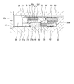
- FIG. 1 is an axial sectional view of a magnetorheological fluid shock absorber according to an embodiment of the present invention.
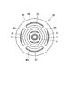
- FIG. 2 is a left side view of the piston in FIG.
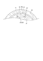
- FIG. 3 is a cross-sectional view in the radial direction of the regulating member according to the embodiment of the present invention.
- FIG. 4 is an enlarged view of the vicinity of the fail valve in FIG.
- FIG. 5 is an enlarged view of the vicinity of the fail valve in the modified example.
- buffer magnetorheological fluid shock absorber
- the shock absorber 100 is a damper whose damping coefficient can be changed by using a magnetorheological fluid whose viscosity changes due to the action of a magnetic field.
- the shock absorber 100 is interposed, for example, between a vehicle body and an axle in a vehicle such as an automobile.
- the shock absorber 100 generates a damping force that suppresses vibration of the vehicle body by an expansion and contraction operation.
- the shock absorber 100 includes a cylinder 10 enclosing a magnetorheological fluid therein, a piston rod 21 extending to the outside of the cylinder 10, and a piston 20 connected to the piston rod 21 and slidably disposed in the cylinder 10. And comprising.
- the piston rod 21 moves forward and backward with respect to the cylinder 10 as the piston 20 moves.
- the cylinder 10 is formed in a bottomed cylindrical shape.
- the magnetorheological fluid sealed in the cylinder 10 has a change in apparent viscosity due to the action of a magnetic field, and is a liquid in which fine particles having ferromagnetism are dispersed in a liquid such as oil.
- the viscosity of the magnetorheological fluid changes according to the strength of the applied magnetic field, and returns to its original state when the magnetic field is no longer affected.
- a gas chamber (not shown) in which gas is sealed is defined via a free piston (not shown).
- the volume change in the cylinder 10 due to the advance / retreat of the piston rod 21 is compensated by the gas chamber.
- the piston 20 partitions the first fluid chamber 11 and the second fluid chamber 12 in the cylinder 10.
- the piston 20 has an annular communication passage 22 that allows a magnetorheological fluid to flow between the first fluid chamber 11 and the second fluid chamber 12. The configuration of the piston 20 will be described later in detail.
- the piston rod 21 is formed coaxially with the piston 20.
- the piston rod 21 has one end 21 a fixed to the piston 20 and the other end 21 b extending to the outside of the cylinder 10.
- the piston rod 21 has a cylindrical shape in which a through hole 21c is formed across one end 21a and the other end 21b.
- a male screw 21 d that is screwed with the piston 20 is formed on the outer peripheral surface of the piston rod 21.
- the piston 20 includes a piston core 30 connected to the piston rod 21, an annular flux ring 35 as a ring body surrounding the outer periphery of the piston core 30, and an annular plate provided on the piston core 30 and supporting the flux ring 35. 40, and a fixing nut 50 that is attached to the outer peripheral surface of the piston core 30 and fixes the plate 40 to the piston core 30.
- the piston core 30 is formed by being divided into a coil assembly 33 provided with a coil 33a and a first core 31 and a second core 32 sandwiching the coil assembly 33.
- the first core 31 and the second core 32 are fastened by a pair of bolts (not shown) with the coil assembly 33 sandwiched therebetween.
- the first core 31 has a cylindrical first small-diameter portion 31a, a cylindrical second small-diameter portion 31b formed with a larger diameter than the first small-diameter portion 31a, and a second small-diameter portion 31b. And a cylindrical large-diameter portion 31c formed to have a large diameter.
- the first core 31 is formed of a magnetic material.
- a female screw 31d is formed on the inner peripheral surface of the first small diameter portion 31a to be engaged with the male screw 21d of the piston rod 21.
- the first core 31 is fastened to the piston rod 21 by screwing the female screw 31d of the first small diameter portion 31a with the male screw 21d of the piston rod 21.
- a male screw 31e to which the fixing nut 50 is screwed is formed on the outer peripheral surface at the tip of the first small diameter portion 31a.
- the second small diameter portion 31b is coaxially formed continuously with the first small diameter portion 31a in the axial direction.
- a step portion 31g is formed between the first small diameter portion 31a and the second small diameter portion 31b.
- the step portion 31 g is configured such that the inside of the end surface of the plate 40 abuts and the plate 40 is sandwiched between the fixing nut 50.
- the large-diameter portion 31 c is formed coaxially with the second small-diameter portion 31 b in the axial direction and is in contact with the coil assembly 33.
- the second core 32 of the piston core 30 has a columnar large diameter portion 32a and a columnar small diameter portion 32b formed to have a smaller diameter than the large diameter portion 32a.
- the large diameter portion 32 a has an end face 32 c that faces the second fluid chamber 12.
- the small diameter portion 32b is formed coaxially with the large diameter portion 32a continuously in the axial direction.
- the second core 32 is formed of a magnetic material.
- the coil assembly 33 of the piston core 30 includes a cylindrical coil mold portion 33b provided with a coil 33a therein, a connecting portion 33c extending radially inward from one end of the coil mold portion 33b, and an axial direction from the connecting portion 33c. And a cylindrical portion 33d extending to the center.
- the coil assembly 33 is formed by molding a resin in a state where the coil 33a is inserted.
- the coil mold portion 33b is formed so that the inner diameter is substantially the same as the outer diameter of the small diameter portion 32b of the second core 32, and is fitted to the outer peripheral surface of the small diameter portion 32b.
- the coil mold part 33 b and the connecting part 33 c are sandwiched between the first core 31 and the second core 32.
- the cylindrical part 33d is located on the opposite side to the coil mold part 33b with respect to the connecting part 33c.
- the cylindrical portion 33d is formed so that the outer diameter is substantially the same as the inner diameter of the through hole 31h formed in the large diameter portion 31c, and is fitted to the through hole 31h.
- the tip 33e of the cylindrical portion 33d is inserted into the through hole 21c of the piston rod 21.
- An O-ring 34 is provided on the outer peripheral side of the distal end portion 33e of the cylindrical portion 33d.
- the O-ring 34 is compressed in the axial direction by the large diameter portion 31 c of the first core 31 and the piston rod 21, and is compressed in the radial direction by the tip portion 33 e of the coil assembly 33 and the piston rod 21. This prevents the magnetorheological fluid flowing between the piston rod 21 and the first core 31 or between the first core 31 and the coil assembly 33 from leaking into the through hole 21 c of the piston rod 21.
- the piston core 30 is formed by being divided into three members of the first core 31, the second core 32, and the coil assembly 33. Therefore, it is only necessary to form only the coil assembly 33 provided with the coil 33 a by molding and to sandwich the coil assembly 33 between the first core 31 and the second core 32.
- the piston core 30 formed by dividing into three members can easily form the piston core 30 as compared with the case where the piston core 30 is formed as a single body and the molding operation is performed.
- the first core 31 is fixed to the piston rod 21 by screwing the female screw 31d and the male screw 21d, but the coil assembly 33 and the second core 32 are only fitted in the axial direction.
- the second core 32 and the coil assembly 33 are fixed so as to be pressed against the first core 31. Therefore, the piston core 30 can be easily assembled.
- the outer diameter of the large diameter portion 32 a and the coil mold portion 33 b of the second core 32 is formed to be the same as the large diameter portion 31 c of the first core 31. Since the outer diameters of the large-diameter portion 31c of the first core 31, the large-diameter portion 32a of the second core 32, and the coil mold portion 33b are the same, the large-diameter portion 31c of the first core 31 and the second core 32 will be described below.
- the portion composed of the large-diameter portion 32 a and the coil mold portion 33 b is referred to as the “large-diameter portion 30 a” of the piston core 30.
- the flux ring 35 of the piston 20 is formed in a substantially cylindrical shape by a magnetic material.
- the flux ring 35 is formed so that the outer diameter is substantially the same as the inner diameter of the cylinder 10, and the inner diameter is larger than the outer diameter of the large-diameter portion 30 a of the piston core 30. Therefore, an annular gap is formed between the inner peripheral surface 35d of the flux ring 35 and the outer peripheral surface of the large-diameter portion 30a of the piston core 30 over the entire length in the axial direction. This gap functions as the communication path 22 through which the magnetorheological fluid flows.
- the flux ring 35 has a small-diameter portion 35c formed at one end 35a to which the plate 40 is fitted.
- the small diameter portion 35c is formed with a small diameter as compared with other portions of the flux ring 35 so that the plate 40 fits on the outer periphery.
- the coil mold part 33 b faces the communication path 22. For this reason, the magnetic field generated by the coil 33 a acts on the magnetorheological fluid flowing in the communication path 22. That is, the communication path 22 functions as a magnetic gap through which the magnetic flux generated around the coil 33a passes.
- the coil 33a forms a magnetic field by a current supplied from the outside.
- the strength of the magnetic field increases as the current supplied to the coil 33a increases.
- a current is supplied to the coil 33a to form a magnetic field, the apparent viscosity of the magnetorheological fluid flowing through the communication path 22 changes.
- the viscosity of the magnetorheological fluid increases as the magnetic field generated by the coil 33a increases.
- a pair of wires (not shown) for supplying a current to the coil 33a is routed inside the connecting portion 33c and the cylindrical portion 33d.
- the pair of wires are drawn from the tip of the cylindrical portion 33 d and passed through the through hole 21 c of the piston rod 21.
- the plate 40 supports the one end 35a of the flux ring 35 with respect to the piston core 30 and defines the position in the axial direction.
- the outer periphery of the plate 40 is formed to have the same diameter as or less than the outer periphery of the flux ring 35.
- the plate 40 is made of a nonmagnetic material.
- the plate 40 has a plurality of flow paths 40 c that are through holes communicating with the communication path 22.
- the flow paths 40c are formed in an arc shape and are arranged at equiangular intervals. In the present embodiment, the flow paths 40c are formed at four locations at 90 ° intervals.
- the flow path 40c is not limited to an arc shape, and may be a plurality of circular through holes, for example.
- connection space 25 that connects the flow path 40 c and the communication path 22 is formed between the plate 40 and the large-diameter portion 31 c of the first core 31.
- the connection space 25 is an annular gap formed on the outer periphery of the second small diameter portion 31b.
- the magnetorheological fluid that has flowed into the piston core 30 from the flow path 40 c flows into the communication path 22 via the connection space 25.
- the first fluid chamber 11 and the second fluid chamber 12 communicate with each other through the flow path 40 c, the connection space 25, and the communication path 22.
- a through hole 40a into which the first small diameter portion 31a of the first core 31 is fitted is formed.
- annular flange 40b that fits into the small diameter portion 35c of the one end 35a of the flux ring 35 is formed.
- the flange portion 40 b is formed to protrude in the axial direction toward the flux ring 35.
- the flange portion 40b is fixed by being brazed to the small diameter portion 35c.
- the plate 40 is pressed and clamped against the stepped portion 30d by the fastening force of the fixing nut 50 to the first small diameter portion 31a of the first core 31. Thereby, the position of the axial direction with respect to the piston core 30 of the flux ring 35 fixed to the plate 40 is prescribed
- the fixing nut 50 is formed in a substantially cylindrical shape, and is attached to the outer periphery of the first small diameter portion 31a of the piston core 30.
- the fixing nut 50 is in contact with the plate 40 at the tip 50a.
- the fixing nut 50 is formed with an internal thread 50c that is engaged with the external thread 31e of the first core 31 on the inner periphery of the base end portion 50b. Thereby, the fixing nut 50 is screwed to the first small diameter portion 31a.
- the plate 40 attached to the one end 35a of the flux ring 35 is formed by the step portion 30d of the piston core 30 attached to the end portion of the piston rod 21 and the fixing nut 50 screwed into the first small diameter portion 31a. It is pinched. Thereby, the flux ring 35 is fixed to the piston core 30 in the axial direction.
- the piston 20 includes a recess 31 f formed in the outer peripheral surface of the piston core 30, a restriction member 70 accommodated in the recess 31 f, and the restriction member 70 protruding into the communication path 22.
- An introduction channel 37 that guides the magnetorheological fluid in the first fluid chamber 11 into the recess 31f in a direction to be moved, and a fail valve 60 that opens and closes the introduction channel 37 are further provided.
- the recess 31 f is formed in a groove shape extending in a certain range in the circumferential direction on the outer peripheral surface of the first core 31.
- the opposing side surfaces of the recess 31f in the axial direction and the radial direction are formed to be parallel to each other.
- the regulating member 70 is formed so as to be fitted into the recess 31f with a slight gap. This prevents the magnetorheological fluid from leaking between the regulating member 70 and the recess 31f.
- the outer side surface 70a facing the communication path 22 of the restricting member 70 is formed with the same curvature as the outer peripheral surface of the first core 31 (see FIG. 3).
- a spring 71 is provided between the regulating member 70 and the bottom of the recess 31f.
- the spring 71 is set to have a natural length when the restricting member 70 is located at a position flush with the outer peripheral surface of the first core 31. Thereby, even if the regulating member 70 is pushed into the recess 31 f, the regulating member 70 is pushed back to a position where the outer surface 70 a is flush with the outer circumferential surface of the first core 31 by the biasing force of the spring 71.
- the introduction channel 37 communicates with the connection space 25, the first introduction channel 37 a extending in the axial direction through the first core 31, and the first introduction channel 37 a and the fail valve 60 described later.
- a second introduction channel 37c that communicates the accommodation hole 37b and the recess 31f.
- the accommodation hole 37b is formed coaxially with the first introduction channel 37a and has a larger diameter than the first introduction channel 37a.
- a valve seat 37d is provided at the boundary between the first introduction flow path 37a and the accommodation hole 37b.
- the second introduction flow path 37c is formed to be orthogonal to the accommodation hole 37b.
- the fail valve 60 includes a valve body 61 that is provided in the accommodation hole 37b and opens or closes the introduction flow path 37, and a movable core 62 that is connected to the valve body 61 and moves according to the magnetic force generated by the coil 33a.
- the valve body 61 is formed in a conical shape so that the tip portion can be seated on the valve seat 37d.
- the valve body 61 is movably accommodated in a space formed by the accommodation hole 37b and the through-hole 33f formed so as to penetrate the coupling hole 33b of the coil assembly 33 continuously with the accommodation hole 37b.
- the movable core 62 is movably accommodated in a space formed by the through hole 33f and the insertion hole 32d formed in the second core 32 coaxially.
- the valve body 61 and the movable core 62 may be integrally formed.
- the movable core 62 When the current flowing through the coil 33a is equal to or greater than the predetermined value Ia, the movable core 62 is urged toward the valve seat 37d by the magnetic force generated by the coil 33a, and the valve body 61 connected to the movable core 62 is pressed against the valve seat 37d. It is done. Thereby, the introduction flow path 37 is closed by the fail valve 60, and the flow of the magnetorheological fluid from the connection space 25 to the recess 31f is blocked.
- the predetermined current value Ia means that when the shock absorber 100 is extended and the pressure of the first fluid chamber 11 becomes high, the high pressure is supplied from the connection space 25 through the first introduction flow path 37a to the valve body 61. This is the value of the current that generates an urging force that can maintain the valve body 61 in the closed state even when acting on the valve.
- shock absorber 100 configured as described above will be described.
- the communication path 22 between the piston core 30 and the flux ring 35 becomes a magnetic gap through which the magnetic flux generated around the coil 33a passes as described above.
- the magnetic field of the coil 33a acts on the magnetorheological fluid flowing through the communication path 22 during the expansion / contraction operation of the shock absorber 100.
- the adjustment of the damping force generated by the shock absorber 100 is performed by changing the amount of current supplied to the coil 33a and changing the strength of the magnetic field acting on the magnetorheological fluid flowing through the communication path 22. Specifically, as the current supplied to the coil 33a increases, the strength of the magnetic field generated around the coil 33a increases. Therefore, the viscosity of the magnetorheological fluid flowing through the communication path 22 increases, and the damping force generated by the shock absorber 100 increases.
- a current of a predetermined value Ia or higher is always applied to the coil 33a.
- the movable core 62 of the fail valve 60 always generates a biasing force that presses the valve body 61 against the valve seat 37d by the magnetic force generated by the coil 33a, and the introduction flow path 37 is maintained in a closed state.
- a current may not be applied to the coil 33a due to a disconnection or a failure of a control device, or the current applied to the coil 33a may decrease for some reason.
- the shock absorber 100 is unable to generate the magnetic force by the coil 33a, or the magnetic force generated by the coil 33a is reduced.
- the shock absorber 100 extends and the pressure of the magnetorheological fluid in the first fluid chamber 11 becomes high, this high pressure flows into the first introduction flow path 37a from the connection space 25 and the valve body 61. Act on.
- the high-pressure magnetorheological fluid flowing into the first introduction flow path 37a pushes the valve body 61 in the valve opening direction and separates it from the valve seat 37d. Thereby, the introduction flow path 37 is opened, and the connection space 25 and the recess 31f communicate with each other.
- the shock absorber 100 can obtain a constant damping force during the extension operation even when the predetermined damping force cannot be generated by the coil 33a.
- the introduction flow path 37 is configured to communicate with the first fluid chamber 11, but instead, the introduction flow path 37 may be configured to communicate with the second fluid chamber 12.
- the shock absorber 100 can obtain a constant damping force during the contraction operation even when the predetermined damping force cannot be generated by the coil 33a.
- the restriction member 70 and the recess 31f are provided in one place, but a plurality of the restriction member 70 and the recess 31f may be provided. In this case, it is possible to control by one fail valve 60 by providing a branch path from one introduction flow path 37 to the recess 31f, or even if the introduction flow path 37 and the fail valve 60 are provided for each recess 31f. Good.
- the shock absorber 100 when the current applied to the coil 33a is equal to or less than a predetermined value, that is, when a predetermined damping force cannot be generated by the coil 33a, the fail valve 60 opens the introduction flow path 37. For this reason, when the shock absorber 100 is extended or contracted, the high-pressure magnetorheological fluid in the first fluid chamber 11 or the second fluid chamber 12 communicating with the introduction flow path 37 is guided into the recess 31f. Is projected into the communication path 22. As a result, the flow path area of the communication path 22 is reduced, so that the flow of the magnetorheological fluid between the first fluid chamber 11 and the second fluid chamber 12 is restricted and applied to the magnetorheological fluid flowing through the communication path 22. Resistance increases. Therefore, the shock absorber 100 can obtain a constant damping force even when the predetermined damping force cannot be generated by the coil 33a.
- the coil 33a is used as means for urging the movable core 62 of the fail valve 60.
- a coil 64 may be provided.
- the coil 33a and the electromagnetic coil 64 are connected in series.
- the movable core 62 need not be provided.
- the urging force can be directly applied to the valve body 61, so that the set value of the predetermined current value Ia is reduced. Even so, it is possible to obtain an urging force for closing the valve body 61.
- the magnetorheological fluid shock absorber 100 includes a cylinder 10 in which magnetorheological fluid is sealed, a piston 20 connected to the piston rod 21 and movably disposed in the cylinder 10, and a piston 20 that is partitioned in the cylinder 10.
- the first fluid chamber 11 includes a first fluid chamber 11 and a second fluid chamber 12.
- the piston 20 surrounds the outer periphery of the piston core 30 connected to the piston rod 21 and the piston core 30.
- a ring body that forms a communication path 22 that communicates with the second fluid chamber 12, an electromagnetic coil (coil 33a) that generates a magnetic field that acts on the magnetorheological fluid flowing through the communication path 22, and a piston core
- An introductory flow path 37 that guides the magnetorheological fluid in the first fluid chamber 11 or the second fluid chamber 12 into the recess 31f in a direction to be moved, and a fail valve 60 that opens and closes the introductory flow path 37.
- the fail valve 60 opens the introduction flow path 37, so that the regulating member 70 protrudes into the communication path 22.
- the fail valve 60 opens the introduction flow path 37, so that the first fluid chamber 11 or the second fluid chamber 12 is opened. Since the magnetorheological fluid is guided to the concave portion 31 f from the above, the regulating member 70 protrudes into the communication path 22. Thereby, the flow of the magnetorheological fluid between the first fluid chamber 11 and the second fluid chamber 12 is restricted by the restriction member 70. Therefore, a constant damping force can be obtained even when the current applied to the electromagnetic coil (coil 33a) is less than or equal to a predetermined value.
- the fail valve 60 closes the introduction flow path 37 by the magnetic force generated by the electromagnetic coil (coil 33a) provided in the piston 20.
- the electromagnetic coil (coil 33a) provided in the piston 20 is used as a drive source for the fail valve 60, it is not necessary to provide a separate drive source for the fail valve 60.
- the lift type solenoid valve has been described as an example of the fail valve 60.
- a spool type solenoid valve having the valve body 61 as a spool may be used.
Landscapes
- Engineering & Computer Science (AREA)
- General Engineering & Computer Science (AREA)
- Mechanical Engineering (AREA)
- Physics & Mathematics (AREA)
- Electromagnetism (AREA)
- Fluid-Damping Devices (AREA)
Abstract
Description
Claims (2)
- 磁場の強さによって粘性が変化する磁気粘性流体を作動流体とする磁気粘性流体緩衝器であって、
前記磁気粘性流体が封入されるシリンダと、
ピストンロッドに連結され前記シリンダ内に移動自在に配置されるピストンと、
前記ピストンによって前記シリンダ内に区画される第一流体室及び第二流体室と、
を備え、
前記ピストンは、
前記ピストンロッドに連結されるピストンコアと、
前記ピストンコアの外周を取り囲み前記ピストンコアとの間に前記第一流体室と前記第二流体室とを連通する連通路を形成するリング体と、
前記連通路を流れる磁気粘性流体に作用する磁場を発生する電磁コイルと、
前記ピストンコアの外周面に形成された凹部と、
前記凹部内に収容された規制部材と、
前記規制部材を前記連通路内に突出させる方向に前記凹部内に前記第一流体室又は前記第二流体室の磁気粘性流体を導く導入流路と、
前記導入流路を開閉するフェール弁と、を有し、
前記電磁コイルに印加される電流が所定値以下の場合には、前記フェール弁が前記導入流路を開放することで、前記規制部材が前記連通路内に突出される磁気粘性流体緩衝器。 - 請求項1に記載の磁気粘性流体緩衝器であって、
前記フェール弁は、前記ピストンに設けられた前記電磁コイルが発生する磁力によって、前記導入流路を閉鎖する磁気粘性流体緩衝器。
Priority Applications (4)
| Application Number | Priority Date | Filing Date | Title |
|---|---|---|---|
| DE112016006210.9T DE112016006210T5 (de) | 2016-01-12 | 2016-09-09 | Magnetorheologischer Fluiddämpfer |
| CN201680076449.3A CN108474435A (zh) | 2016-01-12 | 2016-09-09 | 磁粘滞性流体缓冲器 |
| US16/060,490 US20180363725A1 (en) | 2016-01-12 | 2016-09-09 | Magneto-rheological fluid damper |
| KR1020187015791A KR20180080292A (ko) | 2016-01-12 | 2016-09-09 | 자기 점성 유체 완충기 |
Applications Claiming Priority (2)
| Application Number | Priority Date | Filing Date | Title |
|---|---|---|---|
| JP2016-003838 | 2016-01-12 | ||
| JP2016003838A JP6088674B1 (ja) | 2016-01-12 | 2016-01-12 | 磁気粘性流体緩衝器 |
Publications (1)
| Publication Number | Publication Date |
|---|---|
| WO2017122389A1 true WO2017122389A1 (ja) | 2017-07-20 |
Family
ID=58185982
Family Applications (1)
| Application Number | Title | Priority Date | Filing Date |
|---|---|---|---|
| PCT/JP2016/076679 Ceased WO2017122389A1 (ja) | 2016-01-12 | 2016-09-09 | 磁気粘性流体緩衝器 |
Country Status (6)
| Country | Link |
|---|---|
| US (1) | US20180363725A1 (ja) |
| JP (1) | JP6088674B1 (ja) |
| KR (1) | KR20180080292A (ja) |
| CN (1) | CN108474435A (ja) |
| DE (1) | DE112016006210T5 (ja) |
| WO (1) | WO2017122389A1 (ja) |
Cited By (1)
| Publication number | Priority date | Publication date | Assignee | Title |
|---|---|---|---|---|
| CN108488301A (zh) * | 2018-05-16 | 2018-09-04 | 南京林业大学 | 一种可检测阻尼通道磁场的磁流变阻尼器 |
Families Citing this family (3)
| Publication number | Priority date | Publication date | Assignee | Title |
|---|---|---|---|---|
| EP3477418B1 (en) * | 2016-06-27 | 2021-06-16 | Alps Alpine Co., Ltd. | Operation device and method for controlling same |
| CN110778715A (zh) * | 2019-12-02 | 2020-02-11 | 沈阳众磊道桥有限公司 | 一种动三轴仪用封水止水活塞 |
| CN119981637B (zh) * | 2025-02-18 | 2025-09-19 | 成都佳琛石油机械有限公司 | 旋冲螺杆钻具 |
Citations (4)
| Publication number | Priority date | Publication date | Assignee | Title |
|---|---|---|---|---|
| JPH05312231A (ja) * | 1992-05-11 | 1993-11-22 | Daikin Ind Ltd | 電気粘性流体を用いた減衰定数可変ダンパ |
| JP2009216210A (ja) * | 2008-03-12 | 2009-09-24 | Honda Motor Co Ltd | 減衰力可変ダンパ |
| JP2014181807A (ja) * | 2013-03-21 | 2014-09-29 | Kayaba Ind Co Ltd | 磁気粘性流体緩衝器 |
| JP2015072046A (ja) * | 2013-10-03 | 2015-04-16 | カヤバ工業株式会社 | 液圧緩衝器 |
Family Cites Families (2)
| Publication number | Priority date | Publication date | Assignee | Title |
|---|---|---|---|---|
| JP5986757B2 (ja) * | 2012-03-01 | 2016-09-06 | Kyb株式会社 | 磁気粘性流体緩衝器 |
| JP6340942B2 (ja) | 2014-06-18 | 2018-06-13 | トヨタ自動車株式会社 | 滓還元除去方法と滓還元除去装置 |
-
2016
- 2016-01-12 JP JP2016003838A patent/JP6088674B1/ja not_active Expired - Fee Related
- 2016-09-09 WO PCT/JP2016/076679 patent/WO2017122389A1/ja not_active Ceased
- 2016-09-09 CN CN201680076449.3A patent/CN108474435A/zh active Pending
- 2016-09-09 KR KR1020187015791A patent/KR20180080292A/ko not_active Abandoned
- 2016-09-09 DE DE112016006210.9T patent/DE112016006210T5/de not_active Withdrawn
- 2016-09-09 US US16/060,490 patent/US20180363725A1/en not_active Abandoned
Patent Citations (4)
| Publication number | Priority date | Publication date | Assignee | Title |
|---|---|---|---|---|
| JPH05312231A (ja) * | 1992-05-11 | 1993-11-22 | Daikin Ind Ltd | 電気粘性流体を用いた減衰定数可変ダンパ |
| JP2009216210A (ja) * | 2008-03-12 | 2009-09-24 | Honda Motor Co Ltd | 減衰力可変ダンパ |
| JP2014181807A (ja) * | 2013-03-21 | 2014-09-29 | Kayaba Ind Co Ltd | 磁気粘性流体緩衝器 |
| JP2015072046A (ja) * | 2013-10-03 | 2015-04-16 | カヤバ工業株式会社 | 液圧緩衝器 |
Cited By (1)
| Publication number | Priority date | Publication date | Assignee | Title |
|---|---|---|---|---|
| CN108488301A (zh) * | 2018-05-16 | 2018-09-04 | 南京林业大学 | 一种可检测阻尼通道磁场的磁流变阻尼器 |
Also Published As
| Publication number | Publication date |
|---|---|
| JP2017125526A (ja) | 2017-07-20 |
| JP6088674B1 (ja) | 2017-03-01 |
| KR20180080292A (ko) | 2018-07-11 |
| US20180363725A1 (en) | 2018-12-20 |
| DE112016006210T5 (de) | 2018-09-27 |
| CN108474435A (zh) | 2018-08-31 |
Similar Documents
| Publication | Publication Date | Title |
|---|---|---|
| US10619694B2 (en) | Shock absorber | |
| CN110475985B (zh) | 缓冲器 | |
| US10352390B2 (en) | Damper and method of assembling damper | |
| KR101591221B1 (ko) | 자기 점성 유체 완충기 | |
| JP6088674B1 (ja) | 磁気粘性流体緩衝器 | |
| CN111051730B (zh) | 缓冲器 | |
| CN110998132B (zh) | 阻尼力调节式缓冲器 | |
| WO2017090492A1 (ja) | 減衰力調整式緩衝器 | |
| CN104412000A (zh) | 磁粘滞性流体缓冲器 | |
| US20260066167A1 (en) | Solenoid, damping force adjustment mechanism, and damping force adjustable shock absorber | |
| US20200080612A1 (en) | Hydraulic damping device | |
| JPWO2017145983A1 (ja) | 減衰力調整式緩衝器 | |
| US12181018B2 (en) | Shock absorber | |
| WO2014148292A1 (ja) | 磁気粘性流体緩衝器 | |
| JP2015175515A (ja) | 磁気粘性流体緩衝器 | |
| WO2017051669A1 (ja) | 磁気粘性流体緩衝器 | |
| KR102855080B1 (ko) | 감쇠력 조정식 완충기, 감쇠 밸브 및 솔레노이드 | |
| JP2017053410A (ja) | 磁気粘性流体緩衝器 | |
| WO2017047360A1 (ja) | 緩衝器 | |
| JP2023064403A (ja) | 減衰力調整式緩衝器及びソレノイド | |
| JP2023018353A (ja) | 減衰力発生装置 | |
| JP2025147933A (ja) | 緩衝装置 | |
| JP2017067128A (ja) | 磁気粘性流体緩衝器 |
Legal Events
| Date | Code | Title | Description |
|---|---|---|---|
| 121 | Ep: the epo has been informed by wipo that ep was designated in this application |
Ref document number: 16884992 Country of ref document: EP Kind code of ref document: A1 |
|
| ENP | Entry into the national phase |
Ref document number: 20187015791 Country of ref document: KR Kind code of ref document: A |
|
| WWE | Wipo information: entry into national phase |
Ref document number: 112016006210 Country of ref document: DE |
|
| 122 | Ep: pct application non-entry in european phase |
Ref document number: 16884992 Country of ref document: EP Kind code of ref document: A1 |