WO2017122331A1 - Assistance apparatus, assistance facility, and assistance method - Google Patents
Assistance apparatus, assistance facility, and assistance method Download PDFInfo
- Publication number
- WO2017122331A1 WO2017122331A1 PCT/JP2016/051031 JP2016051031W WO2017122331A1 WO 2017122331 A1 WO2017122331 A1 WO 2017122331A1 JP 2016051031 W JP2016051031 W JP 2016051031W WO 2017122331 A1 WO2017122331 A1 WO 2017122331A1
- Authority
- WO
- WIPO (PCT)
- Prior art keywords
- base
- assistance
- person
- assisted
- rotation
- Prior art date
Links
Images


Classifications
-
- A—HUMAN NECESSITIES
- A61—MEDICAL OR VETERINARY SCIENCE; HYGIENE
- A61G—TRANSPORT, PERSONAL CONVEYANCES, OR ACCOMMODATION SPECIALLY ADAPTED FOR PATIENTS OR DISABLED PERSONS; OPERATING TABLES OR CHAIRS; CHAIRS FOR DENTISTRY; FUNERAL DEVICES
- A61G5/00—Chairs or personal conveyances specially adapted for patients or disabled persons, e.g. wheelchairs
-
- A—HUMAN NECESSITIES
- A61—MEDICAL OR VETERINARY SCIENCE; HYGIENE
- A61G—TRANSPORT, PERSONAL CONVEYANCES, OR ACCOMMODATION SPECIALLY ADAPTED FOR PATIENTS OR DISABLED PERSONS; OPERATING TABLES OR CHAIRS; CHAIRS FOR DENTISTRY; FUNERAL DEVICES
- A61G7/00—Beds specially adapted for nursing; Devices for lifting patients or disabled persons
- A61G7/10—Devices for lifting patients or disabled persons, e.g. special adaptations of hoists thereto
Definitions
- the present invention relates to an assistance device, an assistance facility, and an assistance method.
- Patent Document 1 discloses an assistance robot that assists a person being assisted in standing up and sitting as an assistance device that assists the movement of the person being assisted. Moreover, in assistance equipment, as shown in Patent Document 1, there is a boarding type that allows a person being assisted to board a base provided with wheels. The boarding type assistance device is moved to a predetermined position and rotated by a predetermined angle, for example, by pulling the assistant.
- the wheel may not easily roll against the floor surface depending on the facility environment. If it does so, it may not be easy to adjust to a predetermined angle with respect to a movement target, after moving the assistance apparatus in the state in which the person being assisted got to a predetermined position.
- the present invention has been made in view of such circumstances, and an object thereof is to provide an assistance device, an assistance facility, and an assistance method capable of facilitating rotation around a specified position.
- the assistance device assists the movement of the person being assisted to the movement target.
- the assistance device includes a base on which the person being assisted can board, a moving device that is provided on the base and supports the base so as to be movable with respect to a floor surface, and is provided on the base.
- a support device capable of supporting an assistant in a standing position, and a base provided on the base and engaged with a base provided at a predetermined position with respect to the movement target, with the base on the base at a predetermined position.
- a rotation assist mechanism for assisting the rotation of the base.
- the moving target is installed, and the defining portion that can be engaged with the rotation assist mechanism of the assistance device is provided.
- the assistance method assists the movement of the person being assisted to the movement target using the assistance device.
- the assistance device includes a base on which the person to be assisted can board, a moving device that is provided on the base and supports the base so as to be movable relative to a floor surface, and is provided on the base.
- a support device capable of supporting a person being assisted in a standing posture, and a predetermined portion provided at a predetermined position with respect to the movement target, and provided at the base, and centered on a predetermined position on the base
- the assisting method includes a positioning step of moving the assisting device to the predetermined position where the defining portion is provided, and engaging the positioning assisting mechanism with the defining portion, and positioning the assisting mechanism.
- An angle determining step of maintaining the state engaged with the defining portion and rotating the base to a target angle.
- the rotation assist mechanism is engaged with the defining portion, whereby the movement of the base relative to the defining portion is restricted, and the movement of the rotating shaft passing through the prescribed position is restricted. Thereby, the base is maintained at the positioned position. Therefore, rotation around the specified position is favorably assisted, and the assisting device can be easily adjusted to a specified angle.
- the defining portion is provided according to the movement target. Accordingly, when the assistant moves the assistance device on which the person being assisted is moved to the movement target, the assistance device is positioned at a predetermined angle after the assistance device is positioned at a predetermined position where the engaging portion is provided. It becomes easy to adjust to. As a result, the person being assisted can be quickly moved to the movement target, and the burden on the person being assisted and the person assisted by the movement can be reduced.
- the rotation assist mechanism in the positioning step, is engaged with the defining portion, so that the movement of the base relative to the defining portion is restricted, and the rotating shaft passing through the prescribed position is fixed. .
- the base is maintained with the positioned defining portion. Therefore, rotation around the specified position in the angle determination step is preferably assisted, and the assisting device can be easily adjusted to the specified position and angle.
- the assistance device is an assistance robot that supports the standing person's standing operation and sitting operation.
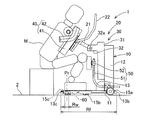
- the assistance robot 1 supports a person M (shown in FIGS. 2 and 3) to support a standing operation from a sitting posture to a standing posture and to support a sitting operation from a standing posture to a sitting posture. Since the assistance robot 1 supports the upper body of the person M who is in the standing posture, one assistance person can pull the assistance robot 1 and move it to a moving target in an assistance facility, for example.
- the “standing posture” means a state where at least the lower body of the person M is standing, and does not mean a state where the upper body is standing.
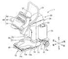
- the assistance robot 1 includes a base 10, a support device 20, an engagement member 60, and a control device 70.
- the front, rear, left, right, up and down are the front, back, left, right, up and down as viewed from the person being assisted as shown in FIG.
- the base 10 is configured such that the person being assisted M can board the vehicle, and is configured to be movable in the front-rear direction and the left-right direction while the person assisted by the person M is riding.
- the base 10 includes a frame 11, a support 12, a foot placing base 13, a fixed cover 14, and a moving device 15.
- the frame 11 of the base 10 is provided at a position slightly separated from the floor surface 2 (grounding surface, ground) and substantially horizontally with respect to the floor surface 2.
- the support column 12 is fixed to the frame 11 and is provided in a state of standing upward from the front upper surface of the frame 11.
- the column 12 is disposed at the center in the left-right direction in front of the frame 11.
- the assistance robot 1 has the one support
- the foot placement table 13 is fixed to the rear of the upper surface of the frame 11 and places the foot of the person being assisted on board.
- a grounding mark 13 a for the foot of the person being assisted M is written on the upper surface of the foot placing table 13.
- the ground mark 13a has a role of guiding the position of the foot to the person being assisted. Further, the position where the pair of foot forms constituting the ground mark 13a is closest to each other corresponds to a specified position Pr of the base 10 described later. With such a configuration, the ground mark 13 a functions as a mark indicating the specified position Pr of the base 10.
- the fixed cover 14 is fixed to the frame 11 or the support column 12 as shown in FIG.
- the fixed cover 14 covers the periphery of the lower portion of the elevating body 31 of the elevating unit 30 in the support device 20 described later, and protects the inside of the support device 20.
- the moving device 15 is provided on the base 10 and supports the base 10 so as to be movable with respect to the floor surface 2. In the present embodiment, the moving device 15 is provided with a plurality of wheels 15a to 15c.
- the plurality of wheels 15a to 15c are provided with four corners (first wheel 15a, third wheel 15c) in the front and rear and left and right sides of the frame 11, and left and right (second wheels 15b) in the middle part in the front and rear direction. It is arranged in a total of 6 places.
- the plurality of wheels 15 a to 15 c are freewheels that can rotate around a rotation axis that is perpendicular to the frame 11.
- the pair of first wheels 15a arranged at the foremost portion of the plurality of wheels 15a to 15c has a lock mechanism that can regulate the rotation around the rolling axis.
- the assistance robot 1 in this embodiment is a boarding type that allows the person being assisted M to board the base 10 on which the moving device 15 is provided.
- the support device 20 is provided on the base 10 and configured to be able to support the person being assisted in a standing posture (see FIG. 3).
- the support device 20 includes an arm 21, a grip 22, an elevating unit 30, a holding unit 40, and a crus pad 50.
- the elevating unit 30 is a mechanism that moves linearly in the vertical direction with respect to the base 10.
- the elevating unit 30 includes an elevating body 31, a swing support unit 32, and an elevating cover 33.
- the elevating body 31 is formed in an elongated shape in the up-down direction.
- the elevating body 31 is provided on the rear surface of the support column 12 so as to be linearly movable in the vertical direction.
- the elevating body 31 is guided by a guide (not shown) on the rear surface of the column 12 and is driven by a linear motion device (not shown).
- the elevating body 31 is surrounded by the fixed cover 14.
- the swing support part 32 is provided on the upper end side of the elevating body 31, and has a swing axis 32a parallel to the left-right direction.
- the elevating cover 33 is fixed to the elevating part 30 and surrounds the elevating body 31 and the swing support part 32. Further, the elevating cover 33 surrounds the support column 12 and the fixed cover 14.
- the assisting robot 1 has one lifting unit 30 corresponding to one support column 12.
- the assistance robot 1 may have a configuration having the number of lifting units 30 corresponding to the number of columns 12.
- the arm 21 is provided so as to be swingable about the swing axis 32a of the swing support part 32 of the elevating part 30 as a central axis.
- the arm 21 is swung by an arm driving device (not shown).
- the assistance robot 1 assists standing up, the arm 21 turns to the front side from the state extending backward.
- the assistance robot 1 performs seating assistance, the arm 21 turns to the rear side so as to extend rearward.
- the holding unit 40 is supported at the tip of the arm 21 so as to be swingable with respect to the elevating unit 30.
- the holding unit 40 holds the upper body of the person being assisted.
- the holding unit 40 includes a body receiving part 41 that contacts the body of the person being assisted M and a side receiving part 42 that holds both sides of the person being assisted M.
- the holding unit 40 may include only one of the body receiving unit 41 and the side receiving unit 42.
- the trunk receiving part 41 supports the trunk of the person being assisted M from below.
- drum receiving part 41 is formed in planar shape, and is formed with a cushion material.
- the torso receiving part 41 is formed in an initial shape corresponding to the body of the standard person being assisted M, and is flexibly deformed according to the body of each person being assisted. In this embodiment, the torso receiving part 41 contacts from the person's M's chest to the abdomen.
- the side receiving portions 42 are formed in an arc shape, and are arranged on the left and right sides of the body receiving portion 41 so that the arc opening faces upward.
- the side support part 42 supports the upper half of the person being assisted M by supporting the side of the person being assisted from below. Furthermore, the side receiving part 42 regulates the back-and-forth movement of the person being assisted by sandwiching both sides of the person being assisted from the front-rear direction. Therefore, the trunk receiving part 41 and the side receiving part 42 can regulate the position of the shoulder of the person being assisted M held by the holding part 40.
- the grip 22 is formed in a U shape, and both ends of the U shape of the grip 22 are fixed to the lower surface of the body receiving portion 41.
- the central portion of the grip 22 is positioned in front of the body receiving portion 41 and is gripped by the person being assisted M held by the holding portion 40.
- the grip 22 is also used when an assistant pulls the assistant robot 1.
- the lower leg pad 50 determines the position and posture of the lower half of the person being assisted in the sitting position by bringing the front part of the lower leg (shin or knee) of the person being assisted in the sitting position. In particular, the position of the foot is determined to some extent.
- the lower thigh pad 50 is fixed to the column 12 of the base 10.
- the crus pad part 50 includes two support members 51 and a crus pad main body 52.
- the support member 51 is formed in an L shape. One end of the L shape of the support member 51 is fixed to the support column 12, and the other end of the L shape of the support member 51 is positioned behind the support column 12.
- the crus pad main body 52 is fixed to the other end side of the support member 51, and is located behind the lifting cover 33 and below the swing support part 32.
- the lower thigh pad main body 52 is a part that contacts the front part of the lower leg of the person being assisted M, is formed in a planar shape, and is formed of a cushion material.
- the engaging member 60 is provided on the base 10.
- the engaging member 60 is a rotation assist mechanism that assists in rotation of the base 10 around the specified position Pr in the base 10 by engaging with a specified portion provided at a predetermined position with respect to the movement target.
- the detailed configuration of the engaging member 60 will be described later.
- the control device 70 controls the vertical movement of the elevating unit 30 and the swinging of the holding unit 40 to support the standing person's standing operation and the sitting operation.
- the control device 70 is fixed to the frame 11 of the base 10 on the side of the column 12.
- the control device 70 supports the standing person's standing operation and the like by controlling the operation of each part in accordance with an operation by the operator (the person being assisted M or the person being assisted) on a controller (not shown).
- the engaging member 60 provided on the base 10 constitutes a rotation assist mechanism of the assisting robot 1.
- the rotation assist mechanism assists the rotation operation of the base 10 configured to be movable and rotatable with respect to the floor surface 2 by the moving device 15.
- the engaging member 60 is rotatably engaged with the pin member 90 installed on the floor surface 2. Detailed configurations of the engaging member 60 and the pin member 90 will be described with reference to FIGS.
- the pin member 90 has a pedestal 91 and a pin body 92 as shown in FIG.
- the pedestal 91 is formed in a disc shape and is fixed to the floor surface 2.
- the pin body 92 is formed in a columnar shape and is provided in a standing state at the center of the pedestal 91.
- the pin member 90 is installed so that the center portion of the pin main body 92 is at a predetermined position with respect to the movement target.
- the pin member 90 is provided at the center in the left-right direction of the toilet 85 on the floor surface 2 of the toilet room 80. It is done.
- the left-right direction of the toilet 85 is the left-right direction seen from the user in a state where the user is seated on the seat surface 86 of the toilet 85.
- the pin member 90 is provided on the floor 2 around the movement target (toilet bowl 85), as well as on a fixed object such as a wall installed around the movement target, or on the movement target itself. Also good.
- the engaging member 60 is rotatably engaged with the pin main body 92 of the pin member 90.
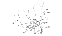
- the engaging member 60 includes a main body portion 61, a bearing portion 62, and a guide portion 63.
- the main body 61 is formed in a plate shape.
- the main body 61 is fixed to the frame 11 of the base 10.
- the bearing portion 62 is located in the central portion of the main body portion 61 and is formed in a semicircular shape that opens to the rear of the base 10.
- the curvature of the bearing portion 62 is set to be approximately the same as or slightly larger than the curvature of the outer peripheral surface of the pin main body 92.
- the center of the bearing portion 62 corresponds to the specified position Pr on the base 10 and serves as the center of the rotation operation assisted by the rotation assist mechanism.
- the specified position Pr of the base 10 is set to a range Rf between the front end portion 13b and the rear end portion 13c of the footrest table 13, as shown in FIG. That is, the central axis in the rotation operation of the base 10 passes through the footrest 13. Thereby, the run-around of the person being assisted can be reduced, and the rotational axis can be brought closer to the center of gravity of the entire person including the person being assisted M, thereby improving the rotation.
- the specified position Pr of the base 10 is set to a range Rw between the pair of third wheels 15c that are arranged facing the left and right directions of the assisting robot 1 at the rearmost portion of the plurality of wheels 15a to 15c. . That is, the pair of third wheels 15c are located approximately at symmetrical positions with the specified position Pr interposed therebetween. Thereby, operation
- the specified position Pr of the base 10 is set at the center in the left-right direction of the assistance robot 1 as shown in FIG.
- the pin member 90 is provided at the center in the left-right direction of the movement target (the toilet bowl 85). Therefore, the assistance robot 1 is centered with respect to the movement target.
- the specified position Pr is set at the center in the left-right direction of the assisting robot 1, the right-and-left bias is eliminated, and the rotation is improved and the interference with the moving target or the like is suppressed.
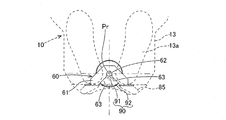
- the guide part 63 guides the relative movement of the pin member 90 with respect to the engaging member 60 when the specified position Pr of the base 10 moves toward the specified part (pin member 90).
- the guide part 63 includes a pair of inclined parts that are inclined so as to further expand the opening of the bearing part 62.
- the guide part 63 is formed in a linear shape. The pin member 90 is guided so as to move along the guide portion 63 toward the bearing portion 62.
- the assistance robot 1 is used for movement between predetermined movement targets in an assistance facility Fs in which various assistances for the person being assisted M are performed.
- the assistance facility Fs a plurality of movement targets are installed, and a pin member 90 (regulating portion) that can be engaged with the engagement member 60 of the assistance robot 1 is provided.
- the assistance facility Fs includes a toilet room 80 in which a toilet 85 as a movement target is installed, as shown in FIG.
- the toilet room 80 is partitioned by a front wall 81 and a rear wall 82 that are disposed to face the toilet 85 in the front-rear direction, and a pair of side walls 83 that are disposed to face the toilet 85 in the left-right direction.
- the entrance / exit 84 of the toilet room 80 is provided on a side wall 83 located on the side of the toilet 85.
- the person to be assisted M When the person to be assisted M is moved to the toilet room 80 having such a configuration, the person to be assisted is directed toward the entrance / exit 84 by facing the assistance robot 1 on which the person assisted by the person M has boarded, as indicated by a thick arrow in FIG. To enter. Then, the assistant positions the assisting robot 1 at a predetermined distance in the front-rear direction with respect to the toilet 85, which is the movement target, and when the assistant M is in the sitting posture, It is necessary to determine the angle of the assisting robot 1 so as to be seated at the position.
- the positioning and angle determination of the assisting robot 1 as described above may not be easy. Specifically, when the space in the toilet room 80 and the area of the entrance / exit 84 are not sufficiently secured, it may be difficult for the assistant to pull the assistance robot 1 or the like. Further, when the floor 2 of the assistance facility Fs is a cushion floor having cushioning properties, the wheels 15a to 15c may sink and the traveling performance of the assistance robot 1 may be reduced.
- the assistance robot 1 carrying the person M to be moved quickly to the movement target and adjusting it to a desired angle contributes to reducing the burden on the person M and the person being assisted.
- the following steps are sequentially performed to appropriately position and determine the angle of the assisting robot 1.
- the assistance robot 1 on which the person being assisted M is boarded is applied to the grip 22 by the assistant and enters backward from the entrance / exit of the toilet room 80.
- the assistant moves the assistance robot 1 backward so that the rear part of the assistance robot 1 faces the toilet 85 that is the movement target. At this time, the assistant recognizes the part of the base 10 that should be brought close to the pin member 90 that is visually recognized (that is, the specified position Pr of the base 10), with the ground mark 13a of the footrest 13 as a mark. To operate. When the assistance robot 1 approaches the pin member 90 to some extent, the guide portion 63 of the engagement member 60 comes into contact with the pin main body 92 of the pin member 90 as shown in FIG.
- the pin member 90 moves relative to the engaging member 60 along the guide portion 63 toward the bearing portion 62. That is, the assistance robot 1 is guided and positioned to a position where the bearing portion 62 of the engaging member 60 is engaged with the pin main body 92 of the pin member 90.
- the specified position Pr of the base 10 coincides with a predetermined position where the pin member 90 is installed.
- the assisting robot 1 When further operating force is applied to the assisting robot 1, the assisting robot 1 is rotated around the engaging position of the engaging member 60 and the pin member 90 (that is, the specified position Pr of the base 10) to determine the angle. Is done. That is, in the angle determination process as described above, as shown in FIG. 8, the engaging member 60 maintains the state of being engaged with the pin member 90, and the base 10 is set to the target angle (the assisting robot 1 is in the toilet bowl). Rotating motion that is rotated up to 85).
- the person being assisted M is supported by the operation of the support device 20 in accordance with the operation of the controller by the assistant, for example, on the seat surface 86 of the toilet 85. After that, the person being assisted M is supported by the operation of the support device 20 and is again in the standing posture.
- the raising / lowering and swinging of the holding portion 40 accompanying the operation of the support device 20 the movement of the base 10 in the left-right direction is restricted by the engagement of the engagement member 60 with the pin member 90. Thereby, the stable stop state of the assistance robot 1 is maintained.
- the assistance robot 1 is rotated and advanced by the operation force of the assistant. Thereby, the engaging member 60 is detached from the pin member 90 and is not engaged with the pin member 90.
- the assistance robot 1 on which the person being assisted M is boarded is withdrawn from the toilet room 80 by traction by the assistant.
- the assistance device (assisting robot 1) assists the person M to be moved to the movement target (toilet bowl 85).
- the assistance device (assisting robot 1) includes a base 10 on which a person M can be boarded, a moving device 15 that is provided on the base 10 and supports the base 10 movably with respect to the floor surface 2, and a base
- a support device 20 provided on the base 10 and capable of supporting the person being assisted in a standing position, and a defining part (pin) provided on the base 10 and provided at a predetermined position with respect to the movement target (toilet bowl 85)
- a rotation assist mechanism (engagement member 60) that engages with the member 90) and assists the rotation of the base 10 about the specified position Pr in the base 10.
- the rotation assist mechanism (engagement member 60) is engaged with the defining portion (pin member 90), so that the movement of the base 10 with respect to the defining portion (pin member 90) is restricted, and the definition is made.
- the movement of the rotating shaft passing through the position Pr is restricted.
- the base 10 is maintained at the positioned position. Therefore, rotation about the specified position Pr is suitably assisted, and it becomes easy to adjust the assistance device (assisting robot 1) to a prescribed angle.
- the defining portion is one of the pin member 90 or the engaging member 60 that is rotatably engaged with the pin member 90.
- the rotation assist mechanism (engagement member 60) is the other of the pin member 90 or the engagement member 60, and the engagement member 60 is engaged with the pin member 90, and the center is a predetermined position Pr that coincides with a predetermined position.
- the rotation of the base 10 is supported. According to such a configuration, the base 10 can be engaged with the defining portion (pin member 90) by the engagement between the pin member 90 and the engagement member 60. With such a configuration, it is possible to configure a rotation assist mechanism (engagement member 60) with high rotation. Further, the relative movement of the engaging member 60 with respect to the pin member 90 is easy, the approaching operation and the detaching operation are easy, and high mobility (running performance) of the assistance device (assisting robot 1) can be ensured.
- the engaging member 60 has a guide portion 63 that guides the relative movement of the pin member 90 relative to the engaging member 60 when the specified position Pr of the base 10 moves toward the specified portion (pin member 90). It is formed. According to such a configuration, since the movement to the defining portion (pin member 90) is guided, the operation of approaching the defining portion (pin member 90) is simplified.
- the assisting person who pulls the assisting device (assisting robot 1) or the control device 70 in the self-propelled type moves the assisting device (assisting robot 1) substantially toward the defining portion (pin member 90), thereby assisting the assisting device.
- the moving locus of the (assisting robot 1) can be properly corrected and positioned. Thereby, the prescribed position Pr of the base 10 can be reached at a predetermined position where the prescribed part (pin member 90) is provided.
- the defining portion is a pin member 90.
- the rotation assist mechanism is an engagement member 60 that can engage with the pin member 90.
- the pin member 90 having a smaller overall dimension than the engaging member 60 is provided as the defining portion.
- the base 10 has the foot mounting base 13 on which the foot of the person M who boarded is mounted.
- the specified position Pr of the base 10 is set in a range between the front end 13b and the rear end 13c of the footrest 13. According to such a configuration, since the center in the rotation operation is located on the footrest 13, the swing of the person being assisted on board is reduced, and the uncomfortable feeling associated with the rotation operation can be reduced. In addition, since the center in the rotation operation is close to the entire center of gravity including the person being assisted M, the rotational performance can be increased, and the external force necessary for the rotation operation (or the driving force in the self-propelled type) can be reduced.
- the moving device 15 is provided with a plurality of wheels 15a to 15c.
- the specified position Pr of the base 10 is set in a range between a pair of wheels (third wheel 15c) arranged facing the left and right direction of the assistance device (assisting robot 1) among the plurality of wheels 15a to 15c.
- the pair of third wheels 15c are generally located at symmetrical positions with the specified position Pr in between, and the rotation about the specified position Pr becomes smooth. Thereby, the rotational property of the base 10 can be improved, and the external force or drive force required for rotation operation can be reduced.
- the support device 20 includes an elevating unit 30 that moves linearly in the vertical direction with respect to the base 10, and a holding unit 40 that is supported to be swingable with respect to the elevating unit 30 and holds the upper body of the person being assisted M.
- the assistance device (assisting robot 1) further includes a control device 70 that controls the vertical movement of the elevating unit 30 and the swinging of the holding unit 40 to support the standing person's standing operation and the sitting operation.
- the assistance device is the assistance robot 1 that supports the standing motion and the sitting motion.
- the assistance robot 1 that is intended for the person M who is not easy to walk is required to perform positioning and angle determination particularly when transferring. Therefore, the application of the present invention to the assisting robot is particularly useful.
- the assistance robot 1 has a larger mass than the assistance device that does not include the lifting unit 30. Therefore, adjustment of the rotation angle is likely to be more difficult, and application of the present invention that can improve the rotation of the assisting robot 1 is particularly useful also from this viewpoint.
- a ground mark 13 a indicating the specified position Pr of the base 10 is provided on the upper surface of the base 10. According to such a configuration, since the assistant can move the assistance device (assisting robot 1) so as to match the ground mark 13a, the movement operation is simplified. Further, in the case of the self-propelled type, it becomes easy to predict the timing of engagement, and it becomes possible to prepare for vibration of engagement and the like.
- the assistance facility Fs is provided with a moving target (toilet bowl 85) and a defining portion (pin member 90) that can be engaged with the rotation assist mechanism (engaging member 60) of the assistance device (assisting robot 1). .
- regulation part (pin member 90) is provided according to the movement target (toilet bowl 85).
- the assistance facility Fs includes a toilet room 80 in which a toilet 85 as a movement target is installed.
- the entrance / exit 84 of the toilet room 80 is provided on a side wall 83 located on the side of the toilet 85.
- the toilet room 80 is provided with the side wall 83, the toilet bowl 85, and the like, and there is a case where sufficient space is not secured for the assistant to operate the assistance device (assisting robot 1). Therefore, application of the present invention is particularly useful.
- the toilet room 80 is provided with a non-movable toilet bowl 85 and the person to be assisted M must be accurately seated on the toilet seat of the toilet bowl 85, the position and angle of the assistance device (assisting robot 1) can be adjusted. There is a high need to do.
- the assistance device (assisting robot 1) can be easily positioned with respect to the toilet seat and the angle can be determined.
- the specified position Pr of the base 10 is set at the center in the left-right direction of the assistance device (assisting robot 1).
- the assistance facility Fs includes a toilet room 80 in which a toilet 85 as a movement target is installed.
- the defining portion (pin member 90) is provided in the center of the toilet 85 in the left-right direction. According to such a configuration, the discomfort of the person being assisted by the rotation operation is reduced, and the assistance device (assisting robot 1) can be reliably moved to a predetermined position or the angle can be adjusted.
- the foot of the person being assisted M is still placed on the foot placing table 13.
- the rotation assist mechanism (engaging member 60) with the defining portion (pin member 90) by maintaining the engagement of the rotation assist mechanism (engaging member 60) with the defining portion (pin member 90), the movement of the assisting device (assisting robot 1) is restricted, and the assisting device (assisting device) A stable stop state of the robot 1) can be maintained. Moreover, since each is arrange
- an assistance method assists the movement of the assistance subject M to the movement target (toilet bowl 85) using an assistance apparatus (assisting robot 1).
- the assistance device (assisting robot 1) includes a base 10 on which a person M can be boarded, a moving device 15 that is provided on the base 10 and supports the base 10 movably with respect to the floor surface 2, and a base A support device 20 provided on the base 10 and capable of supporting the person being assisted in a standing position, and a defining part (pin) provided on the base 10 and provided at a predetermined position with respect to the movement target (toilet bowl 85)
- a rotation assist mechanism (engagement member 60) that engages with the member 90) and assists the rotation of the base 10 about the specified position Pr in the base 10.
- the assistance device (assisting robot 1) is moved to a predetermined position where the defining portion (pin member 90) is provided, and the rotation assist mechanism (engaging member 60) is engaged with the defining portion (pin member 90).
- the rotation assist mechanism (engaging member 60) is engaged with the defining portion (pin member 90), so that the movement of the base 10 with respect to the defining portion (pin member 90) is restricted.
- the rotation axis passing through the specified position Pr is fixed.
- the base 10 maintains the positioned defining portion (pin member 90). Therefore, rotation about the specified position Pr in the angle determination step is preferably assisted, and it becomes easy to adjust the assistance device (assisting robot 1) to the specified position and angle.
- the rotation assist mechanism is the engagement member 60 that can be engaged with a defining portion (pin member 90) provided at a predetermined position with respect to the movement target (the toilet bowl 85 of the toilet room 80).
- a defining portion pin member 90
- a configuration in which the pin member 90 having a small overall size is arranged on the floor 2 side is preferable. .
- the defining portion (pin member 90) disposed on the floor surface 2 may be configured to be detachable. Specifically, for example, an installation hole set to a predetermined depth is formed in the floor surface 2, and a pin is inserted into the installation hole when the assisting robot 1 is moved to the movement target. Even in such a configuration, the same effects as in the embodiment can be obtained.
- a detachable type if the pin is pulled out when not in use, the member protruding from the floor surface 2 can be removed, so that it is possible to prevent an obstacle to the use of others.
- the position of the defining portion (pin member 90) arranged on the floor surface 2 side is appropriately set so that the assisting robot 1 that rotates around the defined position Pr does not interfere with the moving target or the like.
- the defining portion (pin member 90) is a fixed type that is not removable, it is preferable that the defining portion (pin member 90) is installed at a position that does not hinder the use of others.
- the defining portion may be disposed at the center in the left-right direction of the toilet bowl 85 as exemplified in the embodiment, or when the seating surface 86 of the toilet bowl 85 projects forward like a bag from the main body section. May be arranged below the projecting portion.
- the assisting robot 1 is provided with a rotation assist mechanism (engaging member 60) that assists rotation around the specified position Pr, with the specified position Pr being set at the left and right center of the rear side of the base 10. It is done.
- the rotation assist mechanism is configured so that, for example, a specified position is set at the front part or the side part of the base 10 and assists rotation around the specified position. It is good also as a structure provided in the predetermined position of the base 10.
- the pin member 90 is installed in the vicinity of the bed or the bed. Then, the assistance robot 1 is assisted to rotate around the specified position of the front portion or the side portion of the base 10 by the rotation assist mechanism. Even in such a configuration, the same effects as in the embodiment can be obtained.
- the rotation assist mechanism (engagement member 60) is configured to engage with a defining portion (pin member 90) provided at a predetermined position with respect to the movement target.
- the rotation assist mechanism may adopt another configuration as long as it can be engaged with a predetermined position with respect to the movement target.
- the rotation assist mechanism may include a pin support device that supports the pins so that the pins can be moved up and down. The rotation assist mechanism is engaged by lowering a pin in an installation hole provided in the floor surface 2 to assist the rotation operation of the base 10.
- the rotation assist mechanism may include a friction plate support device that supports the friction plate engaged with the floor surface 2 by friction so as to be movable up and down and rotatable.
- the rotation assist mechanism lowers and engages the friction plate at an arbitrary position on the floor surface 2 to assist the rotation operation of the base 10.
- the portion of the floor surface 2 that is engaged with the friction plate corresponds to the “defining portion” of the present invention.
- the defining part on the movement target side and the defined position Pr of the base 10 may not always match.
- the ground mark 13 a functions as a mark indicating the specified position Pr of the base 10.
- a center mark that clearly shows the position that is engaged with the pin member 90 and becomes the center of rotation
- a guide mark that shows the shape of the guide portion 63 of the engaging member 60.
- the assistance device is the assistance robot 1 that includes the elevating unit 30 and the holding unit 40 and supports the standing person's standing operation and sitting operation.
- the assistance device may be configured to raise and lower or swing the holding unit 40 by the operation force of the assistant, regardless of the driving of the linear motion device or the arm driving device in the support device 20.
- the assistance device may be configured not to include the elevating unit 30 or the like. Even in such a configuration, the same effects as in the embodiment can be obtained.
- the assistance robot 1 moves while being pulled by an assistant.
- the assistance robot 1 may be a self-propelled type in which, for example, the moving device 15 has driving wheels and can be self-propelled regardless of the traction of the assistant.
- the control device 70 controls the operation of the moving device 15 of the base 10 so as to execute the entry step, the positioning step, and the angle determination step.
- 1 assistance robot (assistance device), 2: floor surface 10: base 11: frame, 12: support column 13: footrest, 13a: grounding mark, 13b: front end, 13c: rear end, 14: fixed cover, 15: moving device, 15a to 15c: wheels, 20: support device, 21: arm, 22: grip, 30: lifting unit, 31: lifting body 32: Oscillating support part 32a: Oscillating axis 33: Lifting cover 40: Holding part 41: Body receiving part 42: Side receiving part 50: Lower leg support part 51: Support member 52: Lower leg support body 60: Engagement member (rotation assist mechanism) 61: Body part 62: Bearing part 63: Guide part 70: Control device 80: Toilet room 81: Front wall 82: Rear wall 83: Side wall 84: Entrance / exit 85: Toilet (movement target) 86: Seat Surface 90: Pin member (engagement part), 91: Pedestal, 92: Pin main body Fs: Nursing facility, Pr: Specified position, M: Person to be assisted R
Abstract
The purpose of the present invention is to provide an assistance apparatus, assistance facility, and assistance method capable of facilitating rotation centered on a regulatory position. The assistance apparatus is provided with: a base on which a person being assisted can board; a movement device for supporting the base on the floor so as to be movable; a support device capable of supporting the person being assisted to a standing posture; and a rotation-aiding mechanism for engaging with a regulatory part provided at a specified location with respect to a movement destination and aiding the rotation of the base centered on the regulatory position of the base.
Description
本発明は、介助装置、介助施設、および介助方法に関するものである。
The present invention relates to an assistance device, an assistance facility, and an assistance method.
特許文献1には、被介助者の移動を介助する介助装置として、被介助者の起立動作および着座動作を支援する介助ロボットが開示されている。また、介助装置には、特許文献1に示すように、車輪を設けられた基台に被介助者が搭乗可能とする搭乗タイプがある。搭乗タイプの介助装置は、例えば介助者の牽引等によって所定の位置に移動されるとともに所定の角度に回転される。
Patent Document 1 discloses an assistance robot that assists a person being assisted in standing up and sitting as an assistance device that assists the movement of the person being assisted. Moreover, in assistance equipment, as shown in Patent Document 1, there is a boarding type that allows a person being assisted to board a base provided with wheels. The boarding type assistance device is moved to a predetermined position and rotated by a predetermined angle, for example, by pulling the assistant.
搭乗タイプの介助装置に被介助者が搭乗して全体の質量が大きくなると、施設環境によっては、床面に対して車輪が転がりにくくなることがある。そうすると、被介助者が搭乗した状態にある介助装置を所定の位置まで移動させた後に、移動目標に対して所定の角度に調整することが容易でないことがある。
If the person being assisted gets on the boarding type assistance device and the overall mass increases, the wheel may not easily roll against the floor surface depending on the facility environment. If it does so, it may not be easy to adjust to a predetermined angle with respect to a movement target, after moving the assistance apparatus in the state in which the person being assisted got to a predetermined position.
本発明は、このような事情に鑑みてなされたものであり、規定位置を中心とした回転を容易にすることが可能な介助装置、介助施設、および介助方法を提供することを目的とする。
The present invention has been made in view of such circumstances, and an object thereof is to provide an assistance device, an assistance facility, and an assistance method capable of facilitating rotation around a specified position.
請求項1に係る介助装置は、被介助者の移動目標への移動を介助する。介助装置は、前記被介助者が搭乗可能な基台と、前記基台に設けられ、前記基台を床面に対して移動可能に支持する移動装置と、前記基台に設けられ、前記被介助者を立位姿勢に支持可能な支持装置と、前記基台に設けられ、前記移動目標に対して所定の位置に設けられた規定部に係合して前記基台における規定位置を中心とした前記基台の回転を補助する回転補助機構と、を備える。
The assistance device according to claim 1 assists the movement of the person being assisted to the movement target. The assistance device includes a base on which the person being assisted can board, a moving device that is provided on the base and supports the base so as to be movable with respect to a floor surface, and is provided on the base. A support device capable of supporting an assistant in a standing position, and a base provided on the base and engaged with a base provided at a predetermined position with respect to the movement target, with the base on the base at a predetermined position. A rotation assist mechanism for assisting the rotation of the base.
請求項9に係る介助施設は、前記移動目標が設置され、且つ前記介助装置の前記回転補助機構と係合可能な前記規定部が設けられる。
In the assistance facility according to claim 9, the moving target is installed, and the defining portion that can be engaged with the rotation assist mechanism of the assistance device is provided.
請求項12に係る介助方法は、介助装置を用いて移動目標への被介助者の移動を介助する。前記介助装置は、前記被介助者が搭乗可能な基台と、前記基台に設けられ、前記基台を床面に対して移動可能に支持する移動装置と、前記基台に設けられ、前記被介助者を立位姿勢に支持可能な支持装置と、前記基台に設けられ、前記移動目標に対して所定の位置に設けられた規定部に係合して前記基台における規定位置を中心とした前記基台の回転を補助する回転補助機構と、を備える。
前記介助方法は、前記規定部が設けられた前記所定の位置まで前記介助装置を移動させるとともに、前記回転補助機構を前記規定部に係合させて位置決めする位置決め工程と、前記回転補助機構が前記規定部に係合された状態を維持して、前記基台を目標角度まで回転させる角度決め工程と、を備える。 The assistance method according to claim 12 assists the movement of the person being assisted to the movement target using the assistance device. The assistance device includes a base on which the person to be assisted can board, a moving device that is provided on the base and supports the base so as to be movable relative to a floor surface, and is provided on the base. A support device capable of supporting a person being assisted in a standing posture, and a predetermined portion provided at a predetermined position with respect to the movement target, and provided at the base, and centered on a predetermined position on the base A rotation assist mechanism for assisting the rotation of the base.
The assisting method includes a positioning step of moving the assisting device to the predetermined position where the defining portion is provided, and engaging the positioning assisting mechanism with the defining portion, and positioning the assisting mechanism. An angle determining step of maintaining the state engaged with the defining portion and rotating the base to a target angle.
請求項1に係る発明の構成によると、回転補助機構が規定部に係合することにより、規定部に対する基台の移動が規制されて、規定位置を通る回転軸の移動が規制される。これにより、基台は、位置決めされた位置を維持される。よって、規定位置を中心とした回転が好適に補助され、介助装置を規定の角度に調整することが容易となる。
According to the configuration of the invention according to claim 1, the rotation assist mechanism is engaged with the defining portion, whereby the movement of the base relative to the defining portion is restricted, and the movement of the rotating shaft passing through the prescribed position is restricted. Thereby, the base is maintained at the positioned position. Therefore, rotation around the specified position is favorably assisted, and the assisting device can be easily adjusted to a specified angle.
請求項9に係る発明の構成によると、移動目標に応じて規定部が設けられている。これにより、介助者は、当該移動目標へと被介助者を搭乗させた介助装置を移動させる場合に、係合部が設けられた所定の位置において介助装置の位置決めした後に介助装置を所定の角度に調整することが容易となる。これにより、被介助者を移動目標まで迅速に移動させることが可能となり、当該移動に伴う被介助者および介助者の負担を軽減することができる。
According to the configuration of the invention according to claim 9, the defining portion is provided according to the movement target. Accordingly, when the assistant moves the assistance device on which the person being assisted is moved to the movement target, the assistance device is positioned at a predetermined angle after the assistance device is positioned at a predetermined position where the engaging portion is provided. It becomes easy to adjust to. As a result, the person being assisted can be quickly moved to the movement target, and the burden on the person being assisted and the person assisted by the movement can be reduced.
請求項12に係る発明の構成によると、位置決め工程において、回転補助機構が規定部に係合することにより、規定部に対する基台の移動が規制されて、規定位置を通る回転軸が固定される。これにより、基台は、位置決めされた規定部を維持される。よって、角度決め工程における規定位置を中心とした回転が好適に補助され、介助装置を規定の位置および角度に調整することが容易となる。
According to the structure of the twelfth aspect of the present invention, in the positioning step, the rotation assist mechanism is engaged with the defining portion, so that the movement of the base relative to the defining portion is restricted, and the rotating shaft passing through the prescribed position is fixed. . As a result, the base is maintained with the positioned defining portion. Therefore, rotation around the specified position in the angle determination step is preferably assisted, and the assisting device can be easily adjusted to the specified position and angle.
以下、本発明の介助装置、介助施設、および介助方法を具体化した実施形態について図面を参照して説明する。実施形態において、介助装置が被介助者の起立動作および着座動作を支援する介助ロボットである態様を例示する。
Hereinafter, embodiments of the assistance device, assistance facility, and assistance method of the present invention will be described with reference to the drawings. In the embodiment, an aspect in which the assistance device is an assistance robot that supports the standing person's standing operation and sitting operation is illustrated.
<実施形態>
(介助ロボット1の構成)
介助ロボット1は、被介助者M(図2および図3に示す)に対して座位姿勢から立位姿勢への起立動作の支援、および立位姿勢から座位姿勢への着座動作の支援を行う。介助ロボット1が立位姿勢における被介助者Mの上半身を支持することで、一人の介助者が介助ロボット1を牽引等して、例えば介助施設における移動目標に移動させることができる。なお、「立位姿勢」とは、少なくとも被介助者Mの下半身が立っている状態を意味し、上半身が立っている状態を意味するものではない。 <Embodiment>
(Configuration of assistance robot 1)
Theassistance robot 1 supports a person M (shown in FIGS. 2 and 3) to support a standing operation from a sitting posture to a standing posture and to support a sitting operation from a standing posture to a sitting posture. Since the assistance robot 1 supports the upper body of the person M who is in the standing posture, one assistance person can pull the assistance robot 1 and move it to a moving target in an assistance facility, for example. Note that the “standing posture” means a state where at least the lower body of the person M is standing, and does not mean a state where the upper body is standing.
(介助ロボット1の構成)
介助ロボット1は、被介助者M(図2および図3に示す)に対して座位姿勢から立位姿勢への起立動作の支援、および立位姿勢から座位姿勢への着座動作の支援を行う。介助ロボット1が立位姿勢における被介助者Mの上半身を支持することで、一人の介助者が介助ロボット1を牽引等して、例えば介助施設における移動目標に移動させることができる。なお、「立位姿勢」とは、少なくとも被介助者Mの下半身が立っている状態を意味し、上半身が立っている状態を意味するものではない。 <Embodiment>
(Configuration of assistance robot 1)
The
介助ロボット1は、図1および図2に示すように、基台10、支持装置20、係合部材60、制御装置70を備える。以下において、前後左右上下は、図1に示すように、被介助者Mから見た前後左右上下とする。基台10は、被介助者Mが搭乗可能に構成され、被介助者Mが搭乗した状態で前後方向および左右方向に移動可能に構成される。基台10は、図1および図2に示すように、フレーム11と、支柱12と、足載置台13と、固定カバー14と、移動装置15とを備える。
As shown in FIGS. 1 and 2, the assistance robot 1 includes a base 10, a support device 20, an engagement member 60, and a control device 70. In the following, the front, rear, left, right, up and down are the front, back, left, right, up and down as viewed from the person being assisted as shown in FIG. The base 10 is configured such that the person being assisted M can board the vehicle, and is configured to be movable in the front-rear direction and the left-right direction while the person assisted by the person M is riding. As shown in FIG. 1 and FIG. 2, the base 10 includes a frame 11, a support 12, a foot placing base 13, a fixed cover 14, and a moving device 15.
基台10のフレーム11は、床面2(接地面、地面)から僅かに離れた位置であって、床面2に対してほぼ水平に設けられる。支柱12は、フレーム11に固定されており、フレーム11の前方上面から上方に向かって立った状態で設けられる。支柱12は、フレーム11の前方のうち、左右方向中央に配置される。なお、本実施形態において、介助ロボット1は、1本の支柱12を有するが、2本以上の支柱12を備えるようにしてもよい。
The frame 11 of the base 10 is provided at a position slightly separated from the floor surface 2 (grounding surface, ground) and substantially horizontally with respect to the floor surface 2. The support column 12 is fixed to the frame 11 and is provided in a state of standing upward from the front upper surface of the frame 11. The column 12 is disposed at the center in the left-right direction in front of the frame 11. In addition, in this embodiment, although the assistance robot 1 has the one support | pillar 12, you may make it provide the 2 or more support | pillar 12. FIG.
足載置台13は、フレーム11の上面後方に固定され、搭乗した被介助者Mの足を載置される。足載置台13の上面には、被介助者Mの足の接地マーク13aが記されている。接地マーク13aは、被介助者Mに対して足の位置を案内する役割を有する。また、接地マーク13aを構成する一対の足形が互いに最も接近する位置は、後述する基台10の規定位置Prに相当する。このような構成により、接地マーク13aは、基台10の規定位置Prを示すマークとして機能する。
The foot placement table 13 is fixed to the rear of the upper surface of the frame 11 and places the foot of the person being assisted on board. On the upper surface of the foot placing table 13, a grounding mark 13 a for the foot of the person being assisted M is written. The ground mark 13a has a role of guiding the position of the foot to the person being assisted. Further, the position where the pair of foot forms constituting the ground mark 13a is closest to each other corresponds to a specified position Pr of the base 10 described later. With such a configuration, the ground mark 13 a functions as a mark indicating the specified position Pr of the base 10.
固定カバー14は、図1に示すように、フレーム11または支柱12に固定される。固定カバー14は、後述する支持装置20における昇降部30の昇降本体31の下側部分の周囲を覆って、支持装置20の内部を保護する。移動装置15は、基台10に設けられ、基台10を床面2に対して移動可能に支持する。本実施形態において、移動装置15には、複数の車輪15a~15cが設けられる。
The fixed cover 14 is fixed to the frame 11 or the support column 12 as shown in FIG. The fixed cover 14 covers the periphery of the lower portion of the elevating body 31 of the elevating unit 30 in the support device 20 described later, and protects the inside of the support device 20. The moving device 15 is provided on the base 10 and supports the base 10 so as to be movable with respect to the floor surface 2. In the present embodiment, the moving device 15 is provided with a plurality of wheels 15a to 15c.
複数の車輪15a~15cは、図1に示すように、フレーム11の前後左右の四隅(第一車輪15a,第三車輪15c)と、前後方向の中間部に左右(第二車輪15b)との計6箇所に配置される。複数の車輪15a~15cは、フレーム11に対して鉛直な回転軸周りに回転可能な自在輪である。また、複数の車輪15a~15cのうち最前部に配置された一対の第一車輪15aは、転がり軸周りの回転を規制可能なロック機構を有する。このように、本実施形態における介助ロボット1は、移動装置15が設けられた基台10に被介助者Mが搭乗可能とする搭乗タイプである。
As shown in FIG. 1, the plurality of wheels 15a to 15c are provided with four corners (first wheel 15a, third wheel 15c) in the front and rear and left and right sides of the frame 11, and left and right (second wheels 15b) in the middle part in the front and rear direction. It is arranged in a total of 6 places. The plurality of wheels 15 a to 15 c are freewheels that can rotate around a rotation axis that is perpendicular to the frame 11. In addition, the pair of first wheels 15a arranged at the foremost portion of the plurality of wheels 15a to 15c has a lock mechanism that can regulate the rotation around the rolling axis. Thus, the assistance robot 1 in this embodiment is a boarding type that allows the person being assisted M to board the base 10 on which the moving device 15 is provided.
支持装置20は、基台10に設けられ、被介助者Mを立位姿勢に支持可能に構成される(図3を参照)。本実施形態において、支持装置20は、アーム21と、グリップ22と、昇降部30と、保持部40と、下腿当て部50とを有する。昇降部30は、基台10に対して上下方向に直動する機構である。昇降部30は、昇降本体31と、揺動支持部32と、昇降カバー33とを備える。
The support device 20 is provided on the base 10 and configured to be able to support the person being assisted in a standing posture (see FIG. 3). In the present embodiment, the support device 20 includes an arm 21, a grip 22, an elevating unit 30, a holding unit 40, and a crus pad 50. The elevating unit 30 is a mechanism that moves linearly in the vertical direction with respect to the base 10. The elevating unit 30 includes an elevating body 31, a swing support unit 32, and an elevating cover 33.
昇降本体31は、図2に示すように、上下方向に長尺状に形成される。昇降本体31は、支柱12の後面に上下方向に直動可能に設けられる。昇降本体31は、支柱12の後面のガイド(図示せず)に案内されるとともに、直動装置(図示せず)により駆動される。この昇降本体31は、固定カバー14により囲まれている。揺動支持部32は、昇降本体31の上端側に設けられ、左右方向に平行な揺動軸心32aを有する。
As shown in FIG. 2, the elevating body 31 is formed in an elongated shape in the up-down direction. The elevating body 31 is provided on the rear surface of the support column 12 so as to be linearly movable in the vertical direction. The elevating body 31 is guided by a guide (not shown) on the rear surface of the column 12 and is driven by a linear motion device (not shown). The elevating body 31 is surrounded by the fixed cover 14. The swing support part 32 is provided on the upper end side of the elevating body 31, and has a swing axis 32a parallel to the left-right direction.
昇降カバー33は、図1に示すように、昇降部30に固定され、昇降本体31および揺動支持部32を囲む。さらに、昇降カバー33は、支柱12および固定カバー14を囲む。なお、本実施形態においては、介助ロボット1は、1本の支柱12に対応して1個の昇降部30を有する。これに対して、介助ロボット1は、仮に2本以上の支柱12を有する場合には、支柱12の数に対応する数の昇降部30を有する構成としてもよい。
As shown in FIG. 1, the elevating cover 33 is fixed to the elevating part 30 and surrounds the elevating body 31 and the swing support part 32. Further, the elevating cover 33 surrounds the support column 12 and the fixed cover 14. In the present embodiment, the assisting robot 1 has one lifting unit 30 corresponding to one support column 12. On the other hand, if the assistance robot 1 has two or more columns 12, the assistance robot 1 may have a configuration having the number of lifting units 30 corresponding to the number of columns 12.
アーム21は、昇降部30の揺動支持部32の揺動軸心32aを中心軸として揺動可能に設けられる。アーム21は、アーム駆動装置(図示せず)によって揺動される。介助ロボット1が起立補助を行う場合には、アーム21は、後方に延びた状態から前側に旋回する。一方で、介助ロボット1が着座補助を行う場合には、アーム21は、後方に延びる状態となるように後側に旋回する。
The arm 21 is provided so as to be swingable about the swing axis 32a of the swing support part 32 of the elevating part 30 as a central axis. The arm 21 is swung by an arm driving device (not shown). When the assistance robot 1 assists standing up, the arm 21 turns to the front side from the state extending backward. On the other hand, when the assistance robot 1 performs seating assistance, the arm 21 turns to the rear side so as to extend rearward.
保持部40は、アーム21の先端に設けられることにより、昇降部30に対して揺動可能に支持される。保持部40は、被介助者Mの上半身を保持する。本実施形態においては、保持部40は、被介助者Mの胴体に接触する胴体受部41と、被介助者Mの両脇を抱える脇受部42とを備える。なお、保持部40は、胴体受部41と脇受部42の何れか一方のみを備えるようにしてもよい。
The holding unit 40 is supported at the tip of the arm 21 so as to be swingable with respect to the elevating unit 30. The holding unit 40 holds the upper body of the person being assisted. In the present embodiment, the holding unit 40 includes a body receiving part 41 that contacts the body of the person being assisted M and a side receiving part 42 that holds both sides of the person being assisted M. The holding unit 40 may include only one of the body receiving unit 41 and the side receiving unit 42.
胴体受部41は、被介助者Mの胴体を下方から支持する。胴体受部41は、面状に形成され、クッション材により形成される。胴体受部41は、標準的な被介助者Mの胴体に応じた初期形状に形成され、個々の被介助者Mの胴体に応じて柔軟に変形する。本実施形態では、胴体受部41は、被介助者Mの胸部から腹部に亘って接触する。
The trunk receiving part 41 supports the trunk of the person being assisted M from below. The trunk | drum receiving part 41 is formed in planar shape, and is formed with a cushion material. The torso receiving part 41 is formed in an initial shape corresponding to the body of the standard person being assisted M, and is flexibly deformed according to the body of each person being assisted. In this embodiment, the torso receiving part 41 contacts from the person's M's chest to the abdomen.
脇受部42は、円弧状に形成され、円弧開口が上方を向くように胴体受部41の左右それぞれに配置される。脇受部42は、被介助者Mの脇を下方から支持することで、被介助者Mの上半身を支持する。さらに、脇受部42は、被介助者Mの両脇を前後方向から挟むことで、被介助者Mの前後動を規制する。従って、胴体受部41および脇受部42は、保持部40により保持された状態の被介助者Mの肩の位置を規制できる。
The side receiving portions 42 are formed in an arc shape, and are arranged on the left and right sides of the body receiving portion 41 so that the arc opening faces upward. The side support part 42 supports the upper half of the person being assisted M by supporting the side of the person being assisted from below. Furthermore, the side receiving part 42 regulates the back-and-forth movement of the person being assisted by sandwiching both sides of the person being assisted from the front-rear direction. Therefore, the trunk receiving part 41 and the side receiving part 42 can regulate the position of the shoulder of the person being assisted M held by the holding part 40.
グリップ22は、U字状に形成され、グリップ22のU字状の両端が、胴体受部41の下面に固定される。グリップ22の中央部は、胴体受部41の前方に位置し、保持部40に保持された状態の被介助者Mにより把持される。また、グリップ22は、介助者が介助ロボット1を牽引等する場合にも用いられる。
The grip 22 is formed in a U shape, and both ends of the U shape of the grip 22 are fixed to the lower surface of the body receiving portion 41. The central portion of the grip 22 is positioned in front of the body receiving portion 41 and is gripped by the person being assisted M held by the holding portion 40. The grip 22 is also used when an assistant pulls the assistant robot 1.
下腿当て部50は、座位姿勢における被介助者Mの下腿前部(脛部または膝部)を接触させることで、座位姿勢における被介助者Mの下半身の位置および姿勢を決める。特に、足の位置がある程度決定される。下腿当て部50は、基台10の支柱12に固定される。下腿当て部50は、2個の支持部材51と、下腿当て本体52とを備える。
The lower leg pad 50 determines the position and posture of the lower half of the person being assisted in the sitting position by bringing the front part of the lower leg (shin or knee) of the person being assisted in the sitting position. In particular, the position of the foot is determined to some extent. The lower thigh pad 50 is fixed to the column 12 of the base 10. The crus pad part 50 includes two support members 51 and a crus pad main body 52.
支持部材51は、L字状に形成される。支持部材51のL字状の一端が、支柱12に固定され、支持部材51のL字状の他端が、支柱12より後方に位置する。下腿当て本体52は、支持部材51の他端側に固定され、昇降カバー33の後方且つ揺動支持部32の下方に位置する。下腿当て本体52は、被介助者Mの下腿前部を接触させる部位であり、面状に形成され、クッション材により形成される。
The support member 51 is formed in an L shape. One end of the L shape of the support member 51 is fixed to the support column 12, and the other end of the L shape of the support member 51 is positioned behind the support column 12. The crus pad main body 52 is fixed to the other end side of the support member 51, and is located behind the lifting cover 33 and below the swing support part 32. The lower thigh pad main body 52 is a part that contacts the front part of the lower leg of the person being assisted M, is formed in a planar shape, and is formed of a cushion material.
係合部材60は、基台10に設けられる。係合部材60は、移動目標に対して所定の位置に設けられた規定部に係合して基台10における規定位置Prを中心とした基台10の回転を補助する回転補助機構である。係合部材60の詳細構成については後述する。
The engaging member 60 is provided on the base 10. The engaging member 60 is a rotation assist mechanism that assists in rotation of the base 10 around the specified position Pr in the base 10 by engaging with a specified portion provided at a predetermined position with respect to the movement target. The detailed configuration of the engaging member 60 will be described later.
制御装置70は、昇降部30の上下動および保持部40の揺動を制御して、被介助者Mの起立動作および着座動作を支援する。制御装置70は、支柱12の側方において、基台10のフレーム11に固定される。制御装置70は、図示しないコントローラに対する操作者(被介助者Mまたは介助者)による操作に応じて、各部の動作を制御して被介助者Mの起立動作等を支援する。
The control device 70 controls the vertical movement of the elevating unit 30 and the swinging of the holding unit 40 to support the standing person's standing operation and the sitting operation. The control device 70 is fixed to the frame 11 of the base 10 on the side of the column 12. The control device 70 supports the standing person's standing operation and the like by controlling the operation of each part in accordance with an operation by the operator (the person being assisted M or the person being assisted) on a controller (not shown).
(係合部材60およびピン部材90の詳細構成)
基台10に設けられた係合部材60は、上記のように、介助ロボット1の回転補助機構を構成する。回転補助機構は、移動装置15によって床面2に対して移動可能に且つ回転可能に構成された基台10の回転動作を補助する。本実施形態において、係合部材60は、床面2に設置されたピン部材90に回転可能に係合する。係合部材60およびピン部材90の詳細構成について図2~図5を参照して説明する。 (Detailed configuration of the engagingmember 60 and the pin member 90)
As described above, the engagingmember 60 provided on the base 10 constitutes a rotation assist mechanism of the assisting robot 1. The rotation assist mechanism assists the rotation operation of the base 10 configured to be movable and rotatable with respect to the floor surface 2 by the moving device 15. In this embodiment, the engaging member 60 is rotatably engaged with the pin member 90 installed on the floor surface 2. Detailed configurations of the engaging member 60 and the pin member 90 will be described with reference to FIGS.
基台10に設けられた係合部材60は、上記のように、介助ロボット1の回転補助機構を構成する。回転補助機構は、移動装置15によって床面2に対して移動可能に且つ回転可能に構成された基台10の回転動作を補助する。本実施形態において、係合部材60は、床面2に設置されたピン部材90に回転可能に係合する。係合部材60およびピン部材90の詳細構成について図2~図5を参照して説明する。 (Detailed configuration of the engaging
As described above, the engaging
ピン部材90は、図4に示すように、台座91およびピン本体92を有する。本実施形態において、台座91は、円盤状に形成され、床面2に固定されている。ピン本体92は、円柱状に形成され、台座91の中心部において立った状態で設けられている。ピン部材90は、ピン本体92の中心部が移動目標に対して所定の位置となるように設置される。
The pin member 90 has a pedestal 91 and a pin body 92 as shown in FIG. In the present embodiment, the pedestal 91 is formed in a disc shape and is fixed to the floor surface 2. The pin body 92 is formed in a columnar shape and is provided in a standing state at the center of the pedestal 91. The pin member 90 is installed so that the center portion of the pin main body 92 is at a predetermined position with respect to the movement target.
本実施形態において、図5に示すように、例えば移動目標がトイレ室80の便器85である場合に、ピン部材90は、トイレ室80の床面2のうち便器85の左右方向の中央に設けられる。ここで、便器85の左右方向とは、便器85の座面86に利用者が着座した状態において、当該利用者から見た左右方向である。ピン部材90は、上記のように移動目標(便器85)の周辺の床面2に設けられる他に、移動目標の周辺に設置された壁などの固定物、または移動目標自体に設けられる構成としてもよい。
In the present embodiment, as shown in FIG. 5, for example, when the movement target is the toilet 85 of the toilet room 80, the pin member 90 is provided at the center in the left-right direction of the toilet 85 on the floor surface 2 of the toilet room 80. It is done. Here, the left-right direction of the toilet 85 is the left-right direction seen from the user in a state where the user is seated on the seat surface 86 of the toilet 85. As described above, the pin member 90 is provided on the floor 2 around the movement target (toilet bowl 85), as well as on a fixed object such as a wall installed around the movement target, or on the movement target itself. Also good.
係合部材60は、ピン部材90のピン本体92に回転可能に係合する。係合部材60は、図4に示すように、本体部61と、軸受部62と、案内部63とを有する。本体部61は、板状に形成されている。本体部61は、基台10のフレーム11に固定される。軸受部62は、本体部61の中央部に位置し、基台10の後方に開口した半円形状に形成されている。軸受部62の曲率は、ピン本体92の外周面の曲率と同程度または僅かに大きく設定されている。
The engaging member 60 is rotatably engaged with the pin main body 92 of the pin member 90. As shown in FIG. 4, the engaging member 60 includes a main body portion 61, a bearing portion 62, and a guide portion 63. The main body 61 is formed in a plate shape. The main body 61 is fixed to the frame 11 of the base 10. The bearing portion 62 is located in the central portion of the main body portion 61 and is formed in a semicircular shape that opens to the rear of the base 10. The curvature of the bearing portion 62 is set to be approximately the same as or slightly larger than the curvature of the outer peripheral surface of the pin main body 92.
また、軸受部62の中心は、基台10における規定位置Prに相当し、回転補助機構により補助される回転動作の中心となる。本実施形態において、基台10の規定位置Prは、図2に示すように、足載置台13の前端部13bと後端部13cとの間の範囲Rfに設定される。つまり、基台10の回転動作における中心軸が足載置台13を通る。これにより、搭乗している被介助者の振れ回りを小さくでき、また被介助者Mを含む全体の重心に回転軸を近付けて回転性を向上できる。
Further, the center of the bearing portion 62 corresponds to the specified position Pr on the base 10 and serves as the center of the rotation operation assisted by the rotation assist mechanism. In the present embodiment, the specified position Pr of the base 10 is set to a range Rf between the front end portion 13b and the rear end portion 13c of the footrest table 13, as shown in FIG. That is, the central axis in the rotation operation of the base 10 passes through the footrest 13. Thereby, the run-around of the person being assisted can be reduced, and the rotational axis can be brought closer to the center of gravity of the entire person including the person being assisted M, thereby improving the rotation.
また、基台10の規定位置Prは、複数の車輪15a~15cのうち最後部において介助ロボット1の左右方向に対向して配置された一対の第三車輪15cの間の範囲Rwに設定される。つまり、一対の第三車輪15cは、規定位置Prを挟んだ対称位置に概ね位置することになる。これにより、一対の第三車輪15cの動作が安定する。結果として、基台10の回転性を向上させ、回転動作に必要な操作力を低減できる。
Further, the specified position Pr of the base 10 is set to a range Rw between the pair of third wheels 15c that are arranged facing the left and right directions of the assisting robot 1 at the rearmost portion of the plurality of wheels 15a to 15c. . That is, the pair of third wheels 15c are located approximately at symmetrical positions with the specified position Pr interposed therebetween. Thereby, operation | movement of a pair of 3rd wheel 15c is stabilized. As a result, the rotability of the base 10 can be improved and the operating force required for the rotating operation can be reduced.
さらに、基台10の規定位置Prは、図4に示すように、介助ロボット1の左右方向の中央に設定される。これにより、係合部材60がピン部材90に係合した状態で基台10が回転されて所定の角度にされた場合に、ピン部材90が移動目標(便器85)の左右方向の中央に設けられていることから、介助ロボット1が移動目標に対して中央揃えされる。また、規定位置Prを介助ロボット1の左右方向の中央とすることで、左右の偏りをなくして回転性の向上、および移動目標等への干渉の抑制が図られている。
Furthermore, the specified position Pr of the base 10 is set at the center in the left-right direction of the assistance robot 1 as shown in FIG. Thus, when the base 10 is rotated to a predetermined angle with the engaging member 60 engaged with the pin member 90, the pin member 90 is provided at the center in the left-right direction of the movement target (the toilet bowl 85). Therefore, the assistance robot 1 is centered with respect to the movement target. In addition, by setting the specified position Pr at the center in the left-right direction of the assisting robot 1, the right-and-left bias is eliminated, and the rotation is improved and the interference with the moving target or the like is suppressed.
案内部63は、規定部(ピン部材90)に向かって基台10の規定位置Prが移動する場合に、係合部材60に対するピン部材90の相対移動を案内する。具体的には、案内部63は、軸受部62の開口部をさらに拡げるように傾斜した一対の傾斜部により構成される。本実施形態において、案内部63は、直線状に形成される。ピン部材90は、案内部63に沿って軸受部62側へと移動するように案内される。
The guide part 63 guides the relative movement of the pin member 90 with respect to the engaging member 60 when the specified position Pr of the base 10 moves toward the specified part (pin member 90). Specifically, the guide part 63 includes a pair of inclined parts that are inclined so as to further expand the opening of the bearing part 62. In this embodiment, the guide part 63 is formed in a linear shape. The pin member 90 is guided so as to move along the guide portion 63 toward the bearing portion 62.
(回転補助機構による回転動作の補助)
係合部材60(回転補助機構)による基台10の回転動作の補助について、図5~図8を参照して説明する。ここで、介助ロボット1は、被介助者Mを対象とした種々の介助が行われる介助施設Fsにおいて、所定の移動目標の間の移動に用いられる。介助施設Fsには、複数の移動目標が設置され、且つ介助ロボット1の係合部材60に係合可能なピン部材90(規定部)が設けられている。 (Assisting rotation with the rotation assist mechanism)
Assisting the rotational operation of the base 10 by the engaging member 60 (rotation assist mechanism) will be described with reference to FIGS. Here, theassistance robot 1 is used for movement between predetermined movement targets in an assistance facility Fs in which various assistances for the person being assisted M are performed. In the assistance facility Fs, a plurality of movement targets are installed, and a pin member 90 (regulating portion) that can be engaged with the engagement member 60 of the assistance robot 1 is provided.
係合部材60(回転補助機構)による基台10の回転動作の補助について、図5~図8を参照して説明する。ここで、介助ロボット1は、被介助者Mを対象とした種々の介助が行われる介助施設Fsにおいて、所定の移動目標の間の移動に用いられる。介助施設Fsには、複数の移動目標が設置され、且つ介助ロボット1の係合部材60に係合可能なピン部材90(規定部)が設けられている。 (Assisting rotation with the rotation assist mechanism)
Assisting the rotational operation of the base 10 by the engaging member 60 (rotation assist mechanism) will be described with reference to FIGS. Here, the
本実施形態において、介助施設Fsは、図5に示すように、移動目標としての便器85が設置されたトイレ室80を備える。トイレ室80は、便器85の前後方向に対向して配置された前壁81と後壁82、および便器85の左右方向に対向して配置された一対の側壁83により区画されている。トイレ室80の出入り口84は、便器85の側方に位置する側壁83に設けられている。
In this embodiment, the assistance facility Fs includes a toilet room 80 in which a toilet 85 as a movement target is installed, as shown in FIG. The toilet room 80 is partitioned by a front wall 81 and a rear wall 82 that are disposed to face the toilet 85 in the front-rear direction, and a pair of side walls 83 that are disposed to face the toilet 85 in the left-right direction. The entrance / exit 84 of the toilet room 80 is provided on a side wall 83 located on the side of the toilet 85.
このような構成からなるトイレ室80に被介助者Mを移動させる場合に、介助者は、図5の太矢印にて示すように、被介助者Mが搭乗した介助ロボット1を後ろ向きで出入り口84から進入させる。そして、介助者は、移動目標である便器85に対して介助ロボット1が前後方向の所定距離となるように位置決めするとともに、被介助者Mが座位姿勢となった場合に座面86の適切な位置に着座するように介助ロボット1を角度決めする必要がある。
When the person to be assisted M is moved to the toilet room 80 having such a configuration, the person to be assisted is directed toward the entrance / exit 84 by facing the assistance robot 1 on which the person assisted by the person M has boarded, as indicated by a thick arrow in FIG. To enter. Then, the assistant positions the assisting robot 1 at a predetermined distance in the front-rear direction with respect to the toilet 85, which is the movement target, and when the assistant M is in the sitting posture, It is necessary to determine the angle of the assisting robot 1 so as to be seated at the position.
しかしながら、施設環境によっては上記のような介助ロボット1の位置決めや角度決めが容易でないことがある。具体的には、トイレ室80内のスペースや出入り口84の広さが十分に確保されていない場合には、介助者による介助ロボット1の牽引等が困難になるおそれがある。また、介助施設Fsの床面2がクッション性を有するクッションフロアの場合には、複数の車輪15a~15cの沈み込みが発生して介助ロボット1の走行性が低下するおそれがある。
However, depending on the facility environment, the positioning and angle determination of the assisting robot 1 as described above may not be easy. Specifically, when the space in the toilet room 80 and the area of the entrance / exit 84 are not sufficiently secured, it may be difficult for the assistant to pull the assistance robot 1 or the like. Further, when the floor 2 of the assistance facility Fs is a cushion floor having cushioning properties, the wheels 15a to 15c may sink and the traveling performance of the assistance robot 1 may be reduced.
そのため、被介助者Mを搭乗させた介助ロボット1を移動目標まで迅速に移動可能とし、且つ所望の角度に調整可能とすることは、被介助者Mおよび介助者の負担の軽減に貢献する。本実施形態の介助ロボット1および介助施設Fsによると、以下のような工程が順次実行されて、介助ロボット1が適正に位置決めおよび角度決めされる。先ず、進入工程において、被介助者Mが搭乗された介助ロボット1は、介助者によりグリップ22に操作力が加えられて、トイレ室80の出入り口から後ろ向きで進入する。
Therefore, enabling the assistance robot 1 carrying the person M to be moved quickly to the movement target and adjusting it to a desired angle contributes to reducing the burden on the person M and the person being assisted. According to the assisting robot 1 and the assisting facility Fs of the present embodiment, the following steps are sequentially performed to appropriately position and determine the angle of the assisting robot 1. First, in the entry process, the assistance robot 1 on which the person being assisted M is boarded is applied to the grip 22 by the assistant and enters backward from the entrance / exit of the toilet room 80.
介助者は、介助ロボット1の後部が移動目標である便器85に向かうように介助ロボット1を後進させる。このとき、介助者は、足載置台13の接地マーク13aを目印にして、視認しているピン部材90に接近させるべき基台10の部位(即ち、基台10の規定位置Pr)を認識して操作する。介助ロボット1がピン部材90にある程度接近すると、図6に示すように、係合部材60の案内部63がピン部材90のピン本体92に接触する。
The assistant moves the assistance robot 1 backward so that the rear part of the assistance robot 1 faces the toilet 85 that is the movement target. At this time, the assistant recognizes the part of the base 10 that should be brought close to the pin member 90 that is visually recognized (that is, the specified position Pr of the base 10), with the ground mark 13a of the footrest 13 as a mark. To operate. When the assistance robot 1 approaches the pin member 90 to some extent, the guide portion 63 of the engagement member 60 comes into contact with the pin main body 92 of the pin member 90 as shown in FIG.
この状態で介助ロボット1に操作力が加えられると、係合部材60に対してピン部材90が案内部63に沿って軸受部62側へと相対移動する。つまり、介助ロボット1は、係合部材60の軸受部62がピン部材90のピン本体92に係合する位置まで案内されるとともに、位置決めされる。上記のような位置決め工程によって、図7に示すように、ピン部材90に係合部材60が係合すると、ピン部材90が設置された所定の位置に基台10の規定位置Prが一致する。
In this state, when an operating force is applied to the assistance robot 1, the pin member 90 moves relative to the engaging member 60 along the guide portion 63 toward the bearing portion 62. That is, the assistance robot 1 is guided and positioned to a position where the bearing portion 62 of the engaging member 60 is engaged with the pin main body 92 of the pin member 90. As shown in FIG. 7, when the engaging member 60 is engaged with the pin member 90 by the positioning process as described above, the specified position Pr of the base 10 coincides with a predetermined position where the pin member 90 is installed.
そして、介助ロボット1にさらに操作力が加えられると、係合部材60とピン部材90の係合位置(即ち、基台10の規定位置Pr)を中心として、介助ロボット1が回転されて角度決めされる。つまり、上記のような角度決め工程において、図8に示すように、係合部材60は、ピン部材90に係合された状態を維持して、基台10が目標角度(介助ロボット1が便器85に対して中央揃えされる角度)まで回転される回転動作を補助する。
When further operating force is applied to the assisting robot 1, the assisting robot 1 is rotated around the engaging position of the engaging member 60 and the pin member 90 (that is, the specified position Pr of the base 10) to determine the angle. Is done. That is, in the angle determination process as described above, as shown in FIG. 8, the engaging member 60 maintains the state of being engaged with the pin member 90, and the base 10 is set to the target angle (the assisting robot 1 is in the toilet bowl). Rotating motion that is rotated up to 85).
被介助者Mは、例えば介助者によるコントローラへの操作に応じた支持装置20の動作によって、便器85の座面86への着座動作を支援される。その後に、被介助者Mは、支持装置20の動作により起立動作を支援されて、再び起立姿勢となる。このような支持装置20の動作に伴う保持部40の昇降および揺動において、ピン部材90への係合部材60の係合により、基台10の左右方向への移動が規制される。これにより、介助ロボット1の安定した停止状態が維持される。
The person being assisted M is supported by the operation of the support device 20 in accordance with the operation of the controller by the assistant, for example, on the seat surface 86 of the toilet 85. After that, the person being assisted M is supported by the operation of the support device 20 and is again in the standing posture. In the raising / lowering and swinging of the holding portion 40 accompanying the operation of the support device 20, the movement of the base 10 in the left-right direction is restricted by the engagement of the engagement member 60 with the pin member 90. Thereby, the stable stop state of the assistance robot 1 is maintained.
介助ロボット1は、介助者による操作力によって回転および前進される。これにより、係合部材60は、ピン部材90から離脱して、ピン部材90と係合しない状態となる。被介助者Mが搭乗された介助ロボット1は、介助者による牽引等により、トイレ室80から退室される。
The assistance robot 1 is rotated and advanced by the operation force of the assistant. Thereby, the engaging member 60 is detached from the pin member 90 and is not engaged with the pin member 90. The assistance robot 1 on which the person being assisted M is boarded is withdrawn from the toilet room 80 by traction by the assistant.
(実施形態および変形態様の構成による効果)
介助装置(介助ロボット1)は、被介助者Mの移動目標(便器85)への移動を介助する。介助装置(介助ロボット1)は、被介助者Mが搭乗可能な基台10と、基台10に設けられ、基台10を床面2に対して移動可能に支持する移動装置15と、基台10に設けられ、被介助者Mを立位姿勢に支持可能な支持装置20と、基台10に設けられ、移動目標(便器85)に対して所定の位置に設けられた規定部(ピン部材90)に係合して基台10における規定位置Prを中心とした基台10の回転を補助する回転補助機構(係合部材60)と、を備える。
このような構成によると、回転補助機構(係合部材60)が規定部(ピン部材90)に係合することにより、規定部(ピン部材90)に対する基台10の移動が規制されて、規定位置Prを通る回転軸の移動が規制される。これにより、基台10は、位置決めされた位置を維持される。よって、規定位置Prを中心とした回転が好適に補助され、介助装置(介助ロボット1)を規定の角度に調整することが容易となる。 (Effects of configuration of embodiment and modification)
The assistance device (assisting robot 1) assists the person M to be moved to the movement target (toilet bowl 85). The assistance device (assisting robot 1) includes a base 10 on which a person M can be boarded, a movingdevice 15 that is provided on the base 10 and supports the base 10 movably with respect to the floor surface 2, and a base A support device 20 provided on the base 10 and capable of supporting the person being assisted in a standing position, and a defining part (pin) provided on the base 10 and provided at a predetermined position with respect to the movement target (toilet bowl 85) A rotation assist mechanism (engagement member 60) that engages with the member 90) and assists the rotation of the base 10 about the specified position Pr in the base 10.
According to such a configuration, the rotation assist mechanism (engagement member 60) is engaged with the defining portion (pin member 90), so that the movement of the base 10 with respect to the defining portion (pin member 90) is restricted, and the definition is made. The movement of the rotating shaft passing through the position Pr is restricted. Thereby, thebase 10 is maintained at the positioned position. Therefore, rotation about the specified position Pr is suitably assisted, and it becomes easy to adjust the assistance device (assisting robot 1) to a prescribed angle.
介助装置(介助ロボット1)は、被介助者Mの移動目標(便器85)への移動を介助する。介助装置(介助ロボット1)は、被介助者Mが搭乗可能な基台10と、基台10に設けられ、基台10を床面2に対して移動可能に支持する移動装置15と、基台10に設けられ、被介助者Mを立位姿勢に支持可能な支持装置20と、基台10に設けられ、移動目標(便器85)に対して所定の位置に設けられた規定部(ピン部材90)に係合して基台10における規定位置Prを中心とした基台10の回転を補助する回転補助機構(係合部材60)と、を備える。
このような構成によると、回転補助機構(係合部材60)が規定部(ピン部材90)に係合することにより、規定部(ピン部材90)に対する基台10の移動が規制されて、規定位置Prを通る回転軸の移動が規制される。これにより、基台10は、位置決めされた位置を維持される。よって、規定位置Prを中心とした回転が好適に補助され、介助装置(介助ロボット1)を規定の角度に調整することが容易となる。 (Effects of configuration of embodiment and modification)
The assistance device (assisting robot 1) assists the person M to be moved to the movement target (toilet bowl 85). The assistance device (assisting robot 1) includes a base 10 on which a person M can be boarded, a moving
According to such a configuration, the rotation assist mechanism (engagement member 60) is engaged with the defining portion (pin member 90), so that the movement of the base 10 with respect to the defining portion (pin member 90) is restricted, and the definition is made. The movement of the rotating shaft passing through the position Pr is restricted. Thereby, the
また、規定部は、ピン部材90または当該ピン部材90に回転可能に係合する係合部材60の一方である。回転補助機構(係合部材60)は、ピン部材90または係合部材60の他方であり、ピン部材90に係合部材60が係合して、所定の位置に一致する規定位置Prを中心とした基台10の回転を補助する。
このような構成によると、ピン部材90と係合部材60との係合によって基台10を規定部(ピン部材90)に対して係合させることができる。このような構成により回転性が高い回転補助機構(係合部材60)を構成できる。また、ピン部材90に対する係合部材60の相対移動が容易であり、接近動作および離脱動作がしやすく、介助装置(介助ロボット1)の高い移動性(走行性)を確保できる。 The defining portion is one of thepin member 90 or the engaging member 60 that is rotatably engaged with the pin member 90. The rotation assist mechanism (engagement member 60) is the other of the pin member 90 or the engagement member 60, and the engagement member 60 is engaged with the pin member 90, and the center is a predetermined position Pr that coincides with a predetermined position. The rotation of the base 10 is supported.
According to such a configuration, thebase 10 can be engaged with the defining portion (pin member 90) by the engagement between the pin member 90 and the engagement member 60. With such a configuration, it is possible to configure a rotation assist mechanism (engagement member 60) with high rotation. Further, the relative movement of the engaging member 60 with respect to the pin member 90 is easy, the approaching operation and the detaching operation are easy, and high mobility (running performance) of the assistance device (assisting robot 1) can be ensured.
このような構成によると、ピン部材90と係合部材60との係合によって基台10を規定部(ピン部材90)に対して係合させることができる。このような構成により回転性が高い回転補助機構(係合部材60)を構成できる。また、ピン部材90に対する係合部材60の相対移動が容易であり、接近動作および離脱動作がしやすく、介助装置(介助ロボット1)の高い移動性(走行性)を確保できる。 The defining portion is one of the
According to such a configuration, the
また、係合部材60には、規定部(ピン部材90)に向かって基台10の規定位置Prが移動する場合に当該係合部材60に対するピン部材90の相対移動を案内する案内部63が形成される。
このような構成によると、規定部(ピン部材90)への移動が案内されるので、規定部(ピン部材90)へと接近させる動作が簡易になる。介助装置(介助ロボット1)を牽引等する介助者、または自走式における制御装置70は、介助装置(介助ロボット1)を規定部(ピン部材90)に向かって概ね移動させることで、介助装置(介助ロボット1)の移動軌跡が適正に修正されて位置決めすることが可能となる。これにより、規定部(ピン部材90)が設けられた所定の位置に基台10の規定位置Prを到達させることができる。 The engagingmember 60 has a guide portion 63 that guides the relative movement of the pin member 90 relative to the engaging member 60 when the specified position Pr of the base 10 moves toward the specified portion (pin member 90). It is formed.
According to such a configuration, since the movement to the defining portion (pin member 90) is guided, the operation of approaching the defining portion (pin member 90) is simplified. The assisting person who pulls the assisting device (assisting robot 1) or thecontrol device 70 in the self-propelled type moves the assisting device (assisting robot 1) substantially toward the defining portion (pin member 90), thereby assisting the assisting device. The moving locus of the (assisting robot 1) can be properly corrected and positioned. Thereby, the prescribed position Pr of the base 10 can be reached at a predetermined position where the prescribed part (pin member 90) is provided.
このような構成によると、規定部(ピン部材90)への移動が案内されるので、規定部(ピン部材90)へと接近させる動作が簡易になる。介助装置(介助ロボット1)を牽引等する介助者、または自走式における制御装置70は、介助装置(介助ロボット1)を規定部(ピン部材90)に向かって概ね移動させることで、介助装置(介助ロボット1)の移動軌跡が適正に修正されて位置決めすることが可能となる。これにより、規定部(ピン部材90)が設けられた所定の位置に基台10の規定位置Prを到達させることができる。 The engaging
According to such a configuration, since the movement to the defining portion (pin member 90) is guided, the operation of approaching the defining portion (pin member 90) is simplified. The assisting person who pulls the assisting device (assisting robot 1) or the
また、規定部は、ピン部材90である。回転補助機構は、ピン部材90と係合可能な係合部材60である。
このような構成によると、係合部材60よりも全体の寸法が小さいピン部材90が規定部として設けられる。これにより、被介助者Mの不使用時において他者の利用の障害物となりにくくすることができる。 The defining portion is apin member 90. The rotation assist mechanism is an engagement member 60 that can engage with the pin member 90.
According to such a configuration, thepin member 90 having a smaller overall dimension than the engaging member 60 is provided as the defining portion. Thereby, when the care receiver M is not used, it can be made difficult to be an obstacle for the use of others.
このような構成によると、係合部材60よりも全体の寸法が小さいピン部材90が規定部として設けられる。これにより、被介助者Mの不使用時において他者の利用の障害物となりにくくすることができる。 The defining portion is a
According to such a configuration, the
また、基台10は、搭乗した被介助者Mの足を載置される足載置台13を有する。基台10の規定位置Prは、足載置台13の前端部13bと後端部13cとの間の範囲に設定される。
このような構成によると、回転動作における中心が足載置台13に位置するので、搭乗している被介助者Mの振れ回りが小さくなり、回転動作に伴う不快感を軽減できる。また、回転動作における中心が被介助者Mを含む全体の重心に近くなるため、回転性を高くすることができ、回転動作に必要な外力(または自走式における駆動力)を低減できる。 Moreover, thebase 10 has the foot mounting base 13 on which the foot of the person M who boarded is mounted. The specified position Pr of the base 10 is set in a range between the front end 13b and the rear end 13c of the footrest 13.
According to such a configuration, since the center in the rotation operation is located on thefootrest 13, the swing of the person being assisted on board is reduced, and the uncomfortable feeling associated with the rotation operation can be reduced. In addition, since the center in the rotation operation is close to the entire center of gravity including the person being assisted M, the rotational performance can be increased, and the external force necessary for the rotation operation (or the driving force in the self-propelled type) can be reduced.
このような構成によると、回転動作における中心が足載置台13に位置するので、搭乗している被介助者Mの振れ回りが小さくなり、回転動作に伴う不快感を軽減できる。また、回転動作における中心が被介助者Mを含む全体の重心に近くなるため、回転性を高くすることができ、回転動作に必要な外力(または自走式における駆動力)を低減できる。 Moreover, the
According to such a configuration, since the center in the rotation operation is located on the
また、移動装置15には、複数の車輪15a~15cが設けられる。基台10の規定位置Prは、複数の車輪15a~15cのうち介助装置(介助ロボット1)の左右方向に対向して配置された一対の車輪(第三車輪15c)の間の範囲に設定される。
このような構成によると、一対の第三車輪15cは、規定位置Prを挟んだ対称位置に概ね位置することになり、規定位置Prを中心とした回転がスムーズになる。これにより、基台10の回転性を向上でき、回転動作に必要な外力または駆動力を低減できる。 The movingdevice 15 is provided with a plurality of wheels 15a to 15c. The specified position Pr of the base 10 is set in a range between a pair of wheels (third wheel 15c) arranged facing the left and right direction of the assistance device (assisting robot 1) among the plurality of wheels 15a to 15c. The
According to such a configuration, the pair ofthird wheels 15c are generally located at symmetrical positions with the specified position Pr in between, and the rotation about the specified position Pr becomes smooth. Thereby, the rotational property of the base 10 can be improved, and the external force or drive force required for rotation operation can be reduced.
このような構成によると、一対の第三車輪15cは、規定位置Prを挟んだ対称位置に概ね位置することになり、規定位置Prを中心とした回転がスムーズになる。これにより、基台10の回転性を向上でき、回転動作に必要な外力または駆動力を低減できる。 The moving
According to such a configuration, the pair of
また、支持装置20は、基台10に対して上下方向に直動する昇降部30と、昇降部30に対して揺動可能に支持され、被介助者Mの上半身を保持する保持部40と、を有する。介助装置(介助ロボット1)は、昇降部30の上下動および保持部40の揺動を制御して、被介助者Mの起立動作および着座動作を支援する制御装置70をさらに備える。
このような構成によると、介助装置は、起立動作と着座動作とを支援する介助ロボット1である。このように、歩行が容易でない被介助者Mを対象とした介助ロボット1には、特に移乗の際の位置決めや角度決めが正確になされることが要求される。そのため、介助ロボットへの本発明の適用は特に有用である。また、昇降部30を有しない介助装置と比較して介助ロボット1は質量が大きくなる。そのため、回転角度の調整がより困難となりやすく、このような観点からも、介助ロボット1の回転性を向上できる本発明の適用は特に有用である。 In addition, thesupport device 20 includes an elevating unit 30 that moves linearly in the vertical direction with respect to the base 10, and a holding unit 40 that is supported to be swingable with respect to the elevating unit 30 and holds the upper body of the person being assisted M. Have. The assistance device (assisting robot 1) further includes a control device 70 that controls the vertical movement of the elevating unit 30 and the swinging of the holding unit 40 to support the standing person's standing operation and the sitting operation.
According to such a configuration, the assistance device is theassistance robot 1 that supports the standing motion and the sitting motion. As described above, the assistance robot 1 that is intended for the person M who is not easy to walk is required to perform positioning and angle determination particularly when transferring. Therefore, the application of the present invention to the assisting robot is particularly useful. Further, the assistance robot 1 has a larger mass than the assistance device that does not include the lifting unit 30. Therefore, adjustment of the rotation angle is likely to be more difficult, and application of the present invention that can improve the rotation of the assisting robot 1 is particularly useful also from this viewpoint.
このような構成によると、介助装置は、起立動作と着座動作とを支援する介助ロボット1である。このように、歩行が容易でない被介助者Mを対象とした介助ロボット1には、特に移乗の際の位置決めや角度決めが正確になされることが要求される。そのため、介助ロボットへの本発明の適用は特に有用である。また、昇降部30を有しない介助装置と比較して介助ロボット1は質量が大きくなる。そのため、回転角度の調整がより困難となりやすく、このような観点からも、介助ロボット1の回転性を向上できる本発明の適用は特に有用である。 In addition, the
According to such a configuration, the assistance device is the
また、基台10の上面には、基台10の規定位置Prを示す接地マーク13aが設けられる。
このような構成によると、介助者は接地マーク13aに合わせるように介助装置(介助ロボット1)を移動させることができるので、移動操作が簡易となる。また、自走式の場合には、係合するタイミングを予測しやすくなり、係合の振動等に備えることが可能となる。 Further, aground mark 13 a indicating the specified position Pr of the base 10 is provided on the upper surface of the base 10.
According to such a configuration, since the assistant can move the assistance device (assisting robot 1) so as to match theground mark 13a, the movement operation is simplified. Further, in the case of the self-propelled type, it becomes easy to predict the timing of engagement, and it becomes possible to prepare for vibration of engagement and the like.
このような構成によると、介助者は接地マーク13aに合わせるように介助装置(介助ロボット1)を移動させることができるので、移動操作が簡易となる。また、自走式の場合には、係合するタイミングを予測しやすくなり、係合の振動等に備えることが可能となる。 Further, a
According to such a configuration, since the assistant can move the assistance device (assisting robot 1) so as to match the
また、介助施設Fsは、移動目標(便器85)が設置され、且つ介助装置(介助ロボット1)の回転補助機構(係合部材60)と係合可能な規定部(ピン部材90)が設けられる。
このような構成によると、移動目標(便器85)に応じて規定部(ピン部材90)が設けられている。これにより、介助者は、当該移動目標(便器85)へと被介助者Mを搭乗させた介助装置(介助ロボット1)を移動させる場合に、係合部が設けられた所定の位置において介助装置(介助ロボット1)の位置決めした後に介助装置(介助ロボット1)を所定の角度に調整することが容易となる。これにより、被介助者Mを移動目標(便器85)まで迅速に移動させることが可能となり、当該移動に伴う被介助者Mおよび介助者の負担を軽減することができる。 The assistance facility Fs is provided with a moving target (toilet bowl 85) and a defining portion (pin member 90) that can be engaged with the rotation assist mechanism (engaging member 60) of the assistance device (assisting robot 1). .
According to such a structure, the prescription | regulation part (pin member 90) is provided according to the movement target (toilet bowl 85). Thus, when the assistant moves the assistance device (assisting robot 1) carrying the person to be assisted M to the movement target (toilet bowl 85), the assistance device at a predetermined position where the engagement portion is provided. After the (assisting robot 1) is positioned, it is easy to adjust the assisting device (assisting robot 1) to a predetermined angle. As a result, the person being assisted M can be quickly moved to the movement target (the toilet 85), and the burden on the person assisted by the person M and the person assisted by the movement can be reduced.
また、介助施設Fsは、移動目標としての便器85が設置されたトイレ室80を備える。トイレ室80の出入り口84は、便器85の側方に位置する側壁83に設けられている。
このような構成によると、トイレ室80は側壁83や便器85などが設置されており、また介助者が介助装置(介助ロボット1)を操作するのに十分なスペースが確保されていない場合もあることから、特に本発明の適用が有用である。また、トイレ室80は、移動不能な便器85が設置され、当該便器85の便座に被介助者Mを正確に着座させる必要があるため、介助装置(介助ロボット1)の位置および角度の調整を行う必要性が高い。これに対して、本発明を適用することにより、簡易に介助装置(介助ロボット1)を便座に対して位置決めし、且つ角度決めすることができる。 Further, the assistance facility Fs includes atoilet room 80 in which a toilet 85 as a movement target is installed. The entrance / exit 84 of the toilet room 80 is provided on a side wall 83 located on the side of the toilet 85.
According to such a configuration, thetoilet room 80 is provided with the side wall 83, the toilet bowl 85, and the like, and there is a case where sufficient space is not secured for the assistant to operate the assistance device (assisting robot 1). Therefore, application of the present invention is particularly useful. Further, since the toilet room 80 is provided with a non-movable toilet bowl 85 and the person to be assisted M must be accurately seated on the toilet seat of the toilet bowl 85, the position and angle of the assistance device (assisting robot 1) can be adjusted. There is a high need to do. On the other hand, by applying the present invention, the assistance device (assisting robot 1) can be easily positioned with respect to the toilet seat and the angle can be determined.
このような構成によると、トイレ室80は側壁83や便器85などが設置されており、また介助者が介助装置(介助ロボット1)を操作するのに十分なスペースが確保されていない場合もあることから、特に本発明の適用が有用である。また、トイレ室80は、移動不能な便器85が設置され、当該便器85の便座に被介助者Mを正確に着座させる必要があるため、介助装置(介助ロボット1)の位置および角度の調整を行う必要性が高い。これに対して、本発明を適用することにより、簡易に介助装置(介助ロボット1)を便座に対して位置決めし、且つ角度決めすることができる。 Further, the assistance facility Fs includes a
According to such a configuration, the
また、基台10の規定位置Prは、介助装置(介助ロボット1)の左右方向の中央に設定される。介助施設Fsは、移動目標としての便器85が設置されたトイレ室80を備える。規定部(ピン部材90)は、便器85の左右方向の中央に設けられる。
このような構成によると、回転動作に伴う被介助者Mの不快感が低減され、介助装置(介助ロボット1)を確実に規定の位置に移動させ、または角度を調整することができる。また、被介助者Mが便座に着座した状態では、なお足載置台13に被介助者Mの足が載置されている。これに対して、規定部(ピン部材90)に対する回転補助機構(係合部材60)の係合が維持されることによって、介助装置(介助ロボット1)の移動を規制して、介助装置(介助ロボット1)の安定した停止状態を維持できる。また、それぞれが中央に配置されているため、振れ回り部位が少なく、介助装置(介助ロボット1)と便器85の干渉を防止できる。また、トイレ室80において、便器85に対する中央位置は、被介助者M以外の利用者の足が使用時にない位置であり、中央配置されたピン部材が障害物とはなりにくい。 Further, the specified position Pr of thebase 10 is set at the center in the left-right direction of the assistance device (assisting robot 1). The assistance facility Fs includes a toilet room 80 in which a toilet 85 as a movement target is installed. The defining portion (pin member 90) is provided in the center of the toilet 85 in the left-right direction.
According to such a configuration, the discomfort of the person being assisted by the rotation operation is reduced, and the assistance device (assisting robot 1) can be reliably moved to a predetermined position or the angle can be adjusted. In addition, in the state where the person being assisted M is seated on the toilet seat, the foot of the person being assisted M is still placed on the foot placing table 13. On the other hand, by maintaining the engagement of the rotation assist mechanism (engaging member 60) with the defining portion (pin member 90), the movement of the assisting device (assisting robot 1) is restricted, and the assisting device (assisting device) A stable stop state of the robot 1) can be maintained. Moreover, since each is arrange | positioned in the center, there are few swinging parts and the interference of the assistance apparatus (assisting robot 1) and thetoilet bowl 85 can be prevented. Moreover, in the toilet room 80, the center position with respect to the toilet bowl 85 is a position where a user's foot other than the person being assisted M is not in use, and the pin member disposed in the center is unlikely to be an obstacle.
このような構成によると、回転動作に伴う被介助者Mの不快感が低減され、介助装置(介助ロボット1)を確実に規定の位置に移動させ、または角度を調整することができる。また、被介助者Mが便座に着座した状態では、なお足載置台13に被介助者Mの足が載置されている。これに対して、規定部(ピン部材90)に対する回転補助機構(係合部材60)の係合が維持されることによって、介助装置(介助ロボット1)の移動を規制して、介助装置(介助ロボット1)の安定した停止状態を維持できる。また、それぞれが中央に配置されているため、振れ回り部位が少なく、介助装置(介助ロボット1)と便器85の干渉を防止できる。また、トイレ室80において、便器85に対する中央位置は、被介助者M以外の利用者の足が使用時にない位置であり、中央配置されたピン部材が障害物とはなりにくい。 Further, the specified position Pr of the
According to such a configuration, the discomfort of the person being assisted by the rotation operation is reduced, and the assistance device (assisting robot 1) can be reliably moved to a predetermined position or the angle can be adjusted. In addition, in the state where the person being assisted M is seated on the toilet seat, the foot of the person being assisted M is still placed on the foot placing table 13. On the other hand, by maintaining the engagement of the rotation assist mechanism (engaging member 60) with the defining portion (pin member 90), the movement of the assisting device (assisting robot 1) is restricted, and the assisting device (assisting device) A stable stop state of the robot 1) can be maintained. Moreover, since each is arrange | positioned in the center, there are few swinging parts and the interference of the assistance apparatus (assisting robot 1) and the
また、介助方法は、介助装置(介助ロボット1)を用いて移動目標(便器85)への被介助者Mの移動を介助する。介助装置(介助ロボット1)は、被介助者Mが搭乗可能な基台10と、基台10に設けられ、基台10を床面2に対して移動可能に支持する移動装置15と、基台10に設けられ、被介助者Mを立位姿勢に支持可能な支持装置20と、基台10に設けられ、移動目標(便器85)に対して所定の位置に設けられた規定部(ピン部材90)に係合して基台10における規定位置Prを中心とした基台10の回転を補助する回転補助機構(係合部材60)と、を備える。
介助方法は、規定部(ピン部材90)が設けられた所定の位置まで介助装置(介助ロボット1)を移動させるとともに、回転補助機構(係合部材60)を規定部(ピン部材90)に係合させて位置決めする位置決め工程と、回転補助機構(係合部材60)が規定部(ピン部材90)に係合された状態を維持して、基台10を目標角度まで回転させる角度決め工程と、を備える。
このような構成によると、位置決め工程において、回転補助機構(係合部材60)が規定部(ピン部材90)に係合することにより、規定部(ピン部材90)に対する基台10の移動が規制されて、規定位置Prを通る回転軸が固定される。これにより、基台10は、位置決めされた規定部(ピン部材90)を維持される。よって、角度決め工程における規定位置Prを中心とした回転が好適に補助され、介助装置(介助ロボット1)を規定の位置および角度に調整することが容易となる。 Moreover, an assistance method assists the movement of the assistance subject M to the movement target (toilet bowl 85) using an assistance apparatus (assisting robot 1). The assistance device (assisting robot 1) includes a base 10 on which a person M can be boarded, a movingdevice 15 that is provided on the base 10 and supports the base 10 movably with respect to the floor surface 2, and a base A support device 20 provided on the base 10 and capable of supporting the person being assisted in a standing position, and a defining part (pin) provided on the base 10 and provided at a predetermined position with respect to the movement target (toilet bowl 85) A rotation assist mechanism (engagement member 60) that engages with the member 90) and assists the rotation of the base 10 about the specified position Pr in the base 10.
In the assistance method, the assistance device (assisting robot 1) is moved to a predetermined position where the defining portion (pin member 90) is provided, and the rotation assist mechanism (engaging member 60) is engaged with the defining portion (pin member 90). A positioning step for positioning together, and an angle determination step for rotating the base 10 to a target angle while maintaining the state where the rotation assist mechanism (engagement member 60) is engaged with the defining portion (pin member 90). .
According to such a configuration, in the positioning step, the rotation assist mechanism (engaging member 60) is engaged with the defining portion (pin member 90), so that the movement of the base 10 with respect to the defining portion (pin member 90) is restricted. Thus, the rotation axis passing through the specified position Pr is fixed. As a result, thebase 10 maintains the positioned defining portion (pin member 90). Therefore, rotation about the specified position Pr in the angle determination step is preferably assisted, and it becomes easy to adjust the assistance device (assisting robot 1) to the specified position and angle.
介助方法は、規定部(ピン部材90)が設けられた所定の位置まで介助装置(介助ロボット1)を移動させるとともに、回転補助機構(係合部材60)を規定部(ピン部材90)に係合させて位置決めする位置決め工程と、回転補助機構(係合部材60)が規定部(ピン部材90)に係合された状態を維持して、基台10を目標角度まで回転させる角度決め工程と、を備える。
このような構成によると、位置決め工程において、回転補助機構(係合部材60)が規定部(ピン部材90)に係合することにより、規定部(ピン部材90)に対する基台10の移動が規制されて、規定位置Prを通る回転軸が固定される。これにより、基台10は、位置決めされた規定部(ピン部材90)を維持される。よって、角度決め工程における規定位置Prを中心とした回転が好適に補助され、介助装置(介助ロボット1)を規定の位置および角度に調整することが容易となる。 Moreover, an assistance method assists the movement of the assistance subject M to the movement target (toilet bowl 85) using an assistance apparatus (assisting robot 1). The assistance device (assisting robot 1) includes a base 10 on which a person M can be boarded, a moving
In the assistance method, the assistance device (assisting robot 1) is moved to a predetermined position where the defining portion (pin member 90) is provided, and the rotation assist mechanism (engaging member 60) is engaged with the defining portion (pin member 90). A positioning step for positioning together, and an angle determination step for rotating the base 10 to a target angle while maintaining the state where the rotation assist mechanism (engagement member 60) is engaged with the defining portion (pin member 90). .
According to such a configuration, in the positioning step, the rotation assist mechanism (engaging member 60) is engaged with the defining portion (pin member 90), so that the movement of the base 10 with respect to the defining portion (pin member 90) is restricted. Thus, the rotation axis passing through the specified position Pr is fixed. As a result, the
<実施形態の変形態様>
(回転補助機構の構成について)
実施形態において、回転補助機構は、移動目標(トイレ室80の便器85)に対して所定の位置に設けられた規定部(ピン部材90)に係合可能な係合部材60である。これに対して、床面2に係合部材が設置され、基台10には、当該係合部材に係合可能なピン部材が設けられる構成としてもよい。但し、床面2に設置される構造体が他者の利用の障害になることを防止する観点からは、全体の寸法が小さいピン部材90が床面2側に配置される構成が好適である。 <Modification of Embodiment>
(About the structure of the rotation assist mechanism)
In the embodiment, the rotation assist mechanism is theengagement member 60 that can be engaged with a defining portion (pin member 90) provided at a predetermined position with respect to the movement target (the toilet bowl 85 of the toilet room 80). On the other hand, it is good also as a structure by which an engaging member is installed in the floor surface 2 and the base 10 is provided with the pin member which can be engaged with the said engaging member. However, from the viewpoint of preventing the structure installed on the floor 2 from becoming an obstacle to the use of others, a configuration in which the pin member 90 having a small overall size is arranged on the floor 2 side is preferable. .
(回転補助機構の構成について)
実施形態において、回転補助機構は、移動目標(トイレ室80の便器85)に対して所定の位置に設けられた規定部(ピン部材90)に係合可能な係合部材60である。これに対して、床面2に係合部材が設置され、基台10には、当該係合部材に係合可能なピン部材が設けられる構成としてもよい。但し、床面2に設置される構造体が他者の利用の障害になることを防止する観点からは、全体の寸法が小さいピン部材90が床面2側に配置される構成が好適である。 <Modification of Embodiment>
(About the structure of the rotation assist mechanism)
In the embodiment, the rotation assist mechanism is the
また、床面2に配置される規定部(ピン部材90)は、着脱可能に設けられる構成としてもよい。具体的には、例えば床面2に所定の深さに設定された設置穴が形成され、介助ロボット1が移動目標に移動される際に、当該設置穴にピンを挿入する。このような構成においても実施形態と同様の効果を奏する。また、着脱式とすることにより、不使用の際にピンを抜いておけば、床面2から突起する部材を除去できるので、他者の利用の障害になることを防止できる。
Further, the defining portion (pin member 90) disposed on the floor surface 2 may be configured to be detachable. Specifically, for example, an installation hole set to a predetermined depth is formed in the floor surface 2, and a pin is inserted into the installation hole when the assisting robot 1 is moved to the movement target. Even in such a configuration, the same effects as in the embodiment can be obtained. In addition, by adopting a detachable type, if the pin is pulled out when not in use, the member protruding from the floor surface 2 can be removed, so that it is possible to prevent an obstacle to the use of others.
また、床面2側に配置される規定部(ピン部材90)の位置は、規定位置Prを中心に回転する介助ロボット1が移動目標等に干渉しないように適宜設定される。また、規定部(ピン部材90)は、着脱式としない固定式とする場合には、他者の利用の障害にならないような位置に設置されることが好ましい。例えば、規定部は、実施形態にて例示したように便器85の左右方向の中央に配置されてもよいし、便器85の座面86が本体部から庇のように前方に張り出している場合には当該張り出している部位の下方に配置されてもよい。
Further, the position of the defining portion (pin member 90) arranged on the floor surface 2 side is appropriately set so that the assisting robot 1 that rotates around the defined position Pr does not interfere with the moving target or the like. Further, in the case where the defining portion (pin member 90) is a fixed type that is not removable, it is preferable that the defining portion (pin member 90) is installed at a position that does not hinder the use of others. For example, the defining portion may be disposed at the center in the left-right direction of the toilet bowl 85 as exemplified in the embodiment, or when the seating surface 86 of the toilet bowl 85 projects forward like a bag from the main body section. May be arranged below the projecting portion.
実施形態において、介助ロボット1には、基台10の後部側の左右中央に規定位置Prが設定され、当該規定位置Prを中心とした回転を補助する回転補助機構(係合部材60)が設けられる。これに対して、回転補助機構は、介助ロボット1の用途に応じて、例えば基台10の前部や側方部に規定位置が設定されて、当該規定位置を中心とした回転を補助するように基台10の所定の位置に設けられる構成としてもよい。
In the embodiment, the assisting robot 1 is provided with a rotation assist mechanism (engaging member 60) that assists rotation around the specified position Pr, with the specified position Pr being set at the left and right center of the rear side of the base 10. It is done. On the other hand, according to the use of the assisting robot 1, the rotation assist mechanism is configured so that, for example, a specified position is set at the front part or the side part of the base 10 and assists rotation around the specified position. It is good also as a structure provided in the predetermined position of the base 10.
例えば、被介助者Mが介助ロボット1からベッドや車椅子などに移乗する場合に、当該ベッド等の近傍またはベッドにピン部材90を設置する。そして、介助ロボット1は、回転補助機構によって、基台10の前部または側方部の規定位置を中心とした回転を補助される。このような構成においても実施形態と同様の効果を奏する。
For example, when the person being assisted M is transferred from the assistance robot 1 to a bed, a wheelchair or the like, the pin member 90 is installed in the vicinity of the bed or the bed. Then, the assistance robot 1 is assisted to rotate around the specified position of the front portion or the side portion of the base 10 by the rotation assist mechanism. Even in such a configuration, the same effects as in the embodiment can be obtained.
実施形態において、回転補助機構(係合部材60)は、移動目標に対して所定の位置に設けられた規定部(ピン部材90)に係合する構成とした。これに対して、回転補助機構は、移動目標に対する所定の位置に係合可能であれば、他の構成を採用し得る。例えば、回転補助機構は、ピンを昇降可能に支持するピン支持装置を備える構成としてもよい。回転補助機構は、床面2に設けられた設置穴にピンを下降させることにより係合し、基台10の回転動作を補助する。
In the embodiment, the rotation assist mechanism (engagement member 60) is configured to engage with a defining portion (pin member 90) provided at a predetermined position with respect to the movement target. On the other hand, the rotation assist mechanism may adopt another configuration as long as it can be engaged with a predetermined position with respect to the movement target. For example, the rotation assist mechanism may include a pin support device that supports the pins so that the pins can be moved up and down. The rotation assist mechanism is engaged by lowering a pin in an installation hole provided in the floor surface 2 to assist the rotation operation of the base 10.
また、回転補助機構は、床面2と摩擦により係合する摩擦板を昇降可能に且つ回転可能に支持する摩擦板支持装置を備えてもよい。回転補助機構は、床面2の任意の位置に摩擦板を下降させて係合し、基台10の回転動作を補助する。このような構成において、摩擦板と係合した床面2の部位が、本発明の「規定部」に相当する。また、上記のような態様によると、移動目標側の規定部と基台10の規定位置Prとは、必ずしも一致しない場合がある。
Further, the rotation assist mechanism may include a friction plate support device that supports the friction plate engaged with the floor surface 2 by friction so as to be movable up and down and rotatable. The rotation assist mechanism lowers and engages the friction plate at an arbitrary position on the floor surface 2 to assist the rotation operation of the base 10. In such a configuration, the portion of the floor surface 2 that is engaged with the friction plate corresponds to the “defining portion” of the present invention. Moreover, according to the above aspects, the defining part on the movement target side and the defined position Pr of the base 10 may not always match.
(マークについて)
実施形態において、接地マーク13aは、基台10の規定位置Prを示すマークとして機能する。これに対して、基台10の上面には、ピン部材90と係合して回転の中心となる位置をより明確に示す中心マークや、係合部材60の案内部63の形状を示す案内マークが設けられる構成としてもよい。これにより、介助者は、中心マークや案内マークを参照して、ピン部材90に対して基台10の後部を接近させればよいかを把握することが容易となる。よって、介助ロボット1の位置決めが容易となり、移動に伴う被介助者および介助者の負担を軽減することができる。 (About the mark)
In the embodiment, theground mark 13 a functions as a mark indicating the specified position Pr of the base 10. On the other hand, on the upper surface of the base 10, a center mark that clearly shows the position that is engaged with the pin member 90 and becomes the center of rotation, and a guide mark that shows the shape of the guide portion 63 of the engaging member 60. May be provided. Thereby, it becomes easy for the assistant to grasp whether the rear part of the base 10 should be brought close to the pin member 90 with reference to the center mark and the guide mark. Therefore, the positioning of the assistance robot 1 is facilitated, and the burden on the person being assisted and the assistance accompanying the movement can be reduced.
実施形態において、接地マーク13aは、基台10の規定位置Prを示すマークとして機能する。これに対して、基台10の上面には、ピン部材90と係合して回転の中心となる位置をより明確に示す中心マークや、係合部材60の案内部63の形状を示す案内マークが設けられる構成としてもよい。これにより、介助者は、中心マークや案内マークを参照して、ピン部材90に対して基台10の後部を接近させればよいかを把握することが容易となる。よって、介助ロボット1の位置決めが容易となり、移動に伴う被介助者および介助者の負担を軽減することができる。 (About the mark)
In the embodiment, the
(介助装置について)
実施形態において、介助装置は、昇降部30および保持部40を備え、被介助者Mの起立動作および着座動作を支援する介助ロボット1である。これに対して、被介助者Mを立位姿勢に支持可能な支持装置20を備え、且つ被介助者Mが搭乗可能に構成された搭乗タイプであれば、介助装置としては種々の態様を適用され得る。例えば、介助装置は、支持装置20における直動装置やアーム駆動装置の駆動によらず、介助者の操作力によって保持部40を昇降させたり揺動させたりする構成としてもよい。また、介助装置は、昇降部30等を有しない構成としてもよい。このような構成においても、実施形態と同様の効果を奏する。 (About assistance devices)
In the embodiment, the assistance device is theassistance robot 1 that includes the elevating unit 30 and the holding unit 40 and supports the standing person's standing operation and sitting operation. On the other hand, as long as it is a boarding type provided with the support device 20 capable of supporting the person being assisted in a standing posture and being able to board the person being assisted, various modes are applied as the assistance device. Can be done. For example, the assistance device may be configured to raise and lower or swing the holding unit 40 by the operation force of the assistant, regardless of the driving of the linear motion device or the arm driving device in the support device 20. Further, the assistance device may be configured not to include the elevating unit 30 or the like. Even in such a configuration, the same effects as in the embodiment can be obtained.
実施形態において、介助装置は、昇降部30および保持部40を備え、被介助者Mの起立動作および着座動作を支援する介助ロボット1である。これに対して、被介助者Mを立位姿勢に支持可能な支持装置20を備え、且つ被介助者Mが搭乗可能に構成された搭乗タイプであれば、介助装置としては種々の態様を適用され得る。例えば、介助装置は、支持装置20における直動装置やアーム駆動装置の駆動によらず、介助者の操作力によって保持部40を昇降させたり揺動させたりする構成としてもよい。また、介助装置は、昇降部30等を有しない構成としてもよい。このような構成においても、実施形態と同様の効果を奏する。 (About assistance devices)
In the embodiment, the assistance device is the
また、実施形態において、介助ロボット1は、介助者により牽引等されて移動する。これに対して、介助ロボット1は、例えば移動装置15が駆動輪を有し、介助者の牽引等によらず自走可能な自走式としてもよい。このような構成において、例えば制御装置70は、実施形態にて例示したように、進入工程、位置決め工程、および角度決め工程を実行するように、基台10の移動装置15の動作を制御する。
In the embodiment, the assistance robot 1 moves while being pulled by an assistant. On the other hand, the assistance robot 1 may be a self-propelled type in which, for example, the moving device 15 has driving wheels and can be self-propelled regardless of the traction of the assistant. In such a configuration, for example, as exemplified in the embodiment, the control device 70 controls the operation of the moving device 15 of the base 10 so as to execute the entry step, the positioning step, and the angle determination step.
1:介助ロボット(介助装置)、 2:床面
10:基台
11:フレーム、 12:支柱
13:足載置台、
13a:接地マーク、 13b:前端部、 13c:後端部
14:固定カバー、 15:移動装置、 15a~15c:車輪
20:支持装置、 21:アーム、 22:グリップ
30:昇降部
31:昇降本体、 32:揺動支持部、 32a:揺動軸心
33:昇降カバー
40:保持部、 41:胴体受部、 42:脇受部
50:下腿当て部、 51:支持部材、 52:下腿当て本体
60:係合部材(回転補助機構)
61:本体部、 62:軸受部、 63:案内部
70:制御装置
80:トイレ室
81:前壁、 82:後壁、 83:側壁、 84:出入り口
85:便器(移動目標)、 86:座面
90:ピン部材(係合部)、 91:台座、 92:ピン本体
Fs:介護施設、 Pr:規定位置、 M:被介助者
Rf:(足載置台が前後方向に位置する)範囲
Rw:(一対の車輪の間の)範囲 1: assistance robot (assistance device), 2: floor surface 10: base 11: frame, 12: support column 13: footrest,
13a: grounding mark, 13b: front end, 13c: rear end, 14: fixed cover, 15: moving device, 15a to 15c: wheels, 20: support device, 21: arm, 22: grip, 30: lifting unit, 31: lifting body 32:Oscillating support part 32a: Oscillating axis 33: Lifting cover 40: Holding part 41: Body receiving part 42: Side receiving part 50: Lower leg support part 51: Support member 52: Lower leg support body 60: Engagement member (rotation assist mechanism)
61: Body part 62: Bearing part 63: Guide part 70: Control device 80: Toilet room 81: Front wall 82: Rear wall 83: Side wall 84: Entrance / exit 85: Toilet (movement target) 86: Seat Surface 90: Pin member (engagement part), 91: Pedestal, 92: Pin main body Fs: Nursing facility, Pr: Specified position, M: Person to be assisted Rf: Range where the footrest is positioned in the front-rear direction Rw: Range (between a pair of wheels)
10:基台
11:フレーム、 12:支柱
13:足載置台、
13a:接地マーク、 13b:前端部、 13c:後端部
14:固定カバー、 15:移動装置、 15a~15c:車輪
20:支持装置、 21:アーム、 22:グリップ
30:昇降部
31:昇降本体、 32:揺動支持部、 32a:揺動軸心
33:昇降カバー
40:保持部、 41:胴体受部、 42:脇受部
50:下腿当て部、 51:支持部材、 52:下腿当て本体
60:係合部材(回転補助機構)
61:本体部、 62:軸受部、 63:案内部
70:制御装置
80:トイレ室
81:前壁、 82:後壁、 83:側壁、 84:出入り口
85:便器(移動目標)、 86:座面
90:ピン部材(係合部)、 91:台座、 92:ピン本体
Fs:介護施設、 Pr:規定位置、 M:被介助者
Rf:(足載置台が前後方向に位置する)範囲
Rw:(一対の車輪の間の)範囲 1: assistance robot (assistance device), 2: floor surface 10: base 11: frame, 12: support column 13: footrest,
13a: grounding mark, 13b: front end, 13c: rear end, 14: fixed cover, 15: moving device, 15a to 15c: wheels, 20: support device, 21: arm, 22: grip, 30: lifting unit, 31: lifting body 32:
61: Body part 62: Bearing part 63: Guide part 70: Control device 80: Toilet room 81: Front wall 82: Rear wall 83: Side wall 84: Entrance / exit 85: Toilet (movement target) 86: Seat Surface 90: Pin member (engagement part), 91: Pedestal, 92: Pin main body Fs: Nursing facility, Pr: Specified position, M: Person to be assisted Rf: Range where the footrest is positioned in the front-rear direction Rw: Range (between a pair of wheels)
Claims (12)
- 被介助者の移動目標への移動を介助する介助装置であって、
前記被介助者が搭乗可能な基台と、
前記基台に設けられ、前記基台を床面に対して移動可能に支持する移動装置と、
前記基台に設けられ、前記被介助者を立位姿勢に支持可能な支持装置と、
前記基台に設けられ、前記移動目標に対して所定の位置に設けられた規定部に係合して前記基台における規定位置を中心とした前記基台の回転を補助する回転補助機構と、
を備える介助装置。 An assistance device for assisting a person to be moved to a movement target,
A base on which the caregiver can board;
A moving device which is provided on the base and supports the base so as to be movable with respect to a floor surface;
A support device provided on the base and capable of supporting the person being assisted in a standing posture;
A rotation assist mechanism that is provided on the base and engages a defining portion provided at a predetermined position with respect to the movement target to assist the rotation of the base around the defined position on the base;
An assistance device comprising: - 前記規定部は、ピン部材または当該ピン部材に回転可能に係合する係合部材の一方であり、
前記回転補助機構は、前記ピン部材または前記係合部材の他方であり、前記ピン部材に前記係合部材が係合して、前記所定の位置に一致する前記規定位置を中心とした前記基台の回転を補助する、請求項1に記載の介助装置。 The defining portion is one of a pin member and an engaging member that rotatably engages with the pin member,
The rotation assisting mechanism is the other of the pin member or the engaging member, and the base is centered on the prescribed position that coincides with the predetermined position when the engaging member is engaged with the pin member. The assisting device according to claim 1, wherein the assisting device assists the rotation of the assisting device. - 前記係合部材には、前記規定部に向かって前記基台の前記規定位置が移動する場合に当該係合部材に対する前記ピン部材の相対移動を案内する案内部が形成される、請求項2に記載の介助装置。 The guide portion for guiding the relative movement of the pin member with respect to the engagement member when the specified position of the base moves toward the defining portion is formed on the engagement member. The assistance device described.
- 前記規定部は、前記ピン部材であり、
前記回転補助機構は、前記ピン部材と係合可能な前記係合部材である、請求項2または3に記載の介助装置。 The defining portion is the pin member,
The assistance device according to claim 2, wherein the rotation assist mechanism is the engagement member that can be engaged with the pin member. - 前記基台は、搭乗した前記被介助者の足を載置される足載置台を有し、
前記基台の前記規定位置は、前記足載置台の前端部と後端部との間の範囲に設定される、請求項1-4の何れか一項に記載の介助装置。 The base has a footrest on which the foot of the person being assisted is placed;
The assistance device according to any one of claims 1 to 4, wherein the specified position of the base is set in a range between a front end portion and a rear end portion of the footrest table. - 前記移動装置には、複数の車輪が設けられ、
前記基台の前記規定位置は、前記複数の車輪のうち前記介助装置の左右方向に対向して配置された一対の車輪の間の範囲に設定される、請求項1-5の何れか一項に記載の介助装置。 The moving device is provided with a plurality of wheels,
6. The prescribed position of the base is set in a range between a pair of wheels arranged opposite to each other in the left-right direction of the assistance device among the plurality of wheels. The assistance device described in 1. - 前記支持装置は、前記基台に対して上下方向に直動する昇降部と、前記昇降部に対して揺動可能に支持され、前記被介助者の上半身を保持する保持部と、を有し、
前記介助装置は、前記昇降部の上下動および前記保持部の揺動を制御して、前記被介助者の起立動作および着座動作を支援する制御装置をさらに備える、請求項1-6の何れか一項に記載の介助装置。 The support device includes an elevating unit that moves linearly in the vertical direction with respect to the base, and a holding unit that is swingably supported with respect to the elevating unit and holds the upper body of the person being assisted. ,
The said assistance apparatus is further equipped with the control apparatus which controls the raising / lowering movement of the said raising / lowering part and the rocking | fluctuation of the said holding | maintenance part, and assists the standing person's standing operation | movement and seating operation | movement. The assistance device according to one item. - 前記基台の上面には、前記基台の前記規定位置を示すマークが設けられる、請求項1-7の何れか一項に記載の介助装置。 The assistance device according to any one of claims 1 to 7, wherein a mark indicating the specified position of the base is provided on an upper surface of the base.
- 前記移動目標が設置され、且つ請求項1-8の何れか一項に記載の前記介助装置の前記回転補助機構と係合可能な前記規定部が設けられた介助施設。 9. An assistance facility in which the moving target is installed and the defining portion that can be engaged with the rotation assist mechanism of the assistance device according to any one of claims 1 to 8.
- 前記介助施設は、前記移動目標としての便器が設置されたトイレ室を備え、
前記トイレ室の出入り口は、前記便器の側方に位置する側壁に設けられている、請求項9に記載の介助施設。 The assistance facility includes a toilet room in which a toilet as the movement target is installed,
The entrance / exit of the said toilet room is an assistance facility of Claim 9 provided in the side wall located in the side of the said toilet bowl. - 前記基台の前記規定位置は、前記介助装置の左右方向の中央に設定され、
前記介助施設は、前記移動目標としての便器が設置されたトイレ室を備え、
前記規定部は、前記便器の左右方向の中央に設けられる、請求項9または10に記載の介助施設。 The prescribed position of the base is set at the center in the left-right direction of the assistance device,
The assistance facility includes a toilet room in which a toilet as the movement target is installed,
The assisting facility according to claim 9 or 10, wherein the defining portion is provided at a center in a left-right direction of the toilet. - 介助装置を用いて移動目標への被介助者の移動を介助する介助方法であって、
前記介助装置は、
前記被介助者が搭乗可能な基台と、
前記基台に設けられ、前記基台を床面に対して移動可能に支持する移動装置と、
前記基台に設けられ、前記被介助者を立位姿勢に支持可能な支持装置と、
前記基台に設けられ、前記移動目標に対して所定の位置に設けられた規定部に係合して前記基台における規定位置を中心とした前記基台の回転を補助する回転補助機構と、を備え、
前記介助方法は、
前記規定部が設けられた前記所定の位置まで前記介助装置を移動させるとともに、前記回転補助機構を前記規定部に係合させて位置決めする位置決め工程と、
前記回転補助機構が前記規定部に係合された状態を維持して、前記基台を目標角度まで回転させる角度決め工程と、
を備える介助方法。 An assistance method for assisting the movement of the person being assisted to the movement target using the assistance device,
The assistance device is:
A base on which the caregiver can board;
A moving device which is provided on the base and supports the base so as to be movable with respect to a floor surface;
A support device provided on the base and capable of supporting the person being assisted in a standing posture;
A rotation assist mechanism that is provided on the base and engages a defining portion provided at a predetermined position with respect to the movement target to assist the rotation of the base around the defined position on the base; With
The assistance method is:
A positioning step of moving the assisting device to the predetermined position where the defining portion is provided, and positioning the rotation assist mechanism by engaging the defining portion;
An angle determination step of rotating the base to a target angle while maintaining the state where the rotation assist mechanism is engaged with the defining portion;
An assistance method comprising:
Priority Applications (14)
| Application Number | Priority Date | Filing Date | Title |
|---|---|---|---|
| PCT/JP2016/051031 WO2017122331A1 (en) | 2016-01-14 | 2016-01-14 | Assistance apparatus, assistance facility, and assistance method |
| JP2017561472A JP6586472B2 (en) | 2016-01-14 | 2016-01-14 | Assistance device, assistance facility, and assistance method |
| JP2017544380A JP6745810B2 (en) | 2015-10-06 | 2016-05-17 | Assistance device |
| SG11201802366QA SG11201802366QA (en) | 2015-10-06 | 2016-05-17 | Assisting apparatus |
| EP16853292.7A EP3360525B1 (en) | 2015-10-06 | 2016-05-17 | Assistance device |
| AU2016336279A AU2016336279B2 (en) | 2015-10-06 | 2016-05-17 | Assistance device |
| PCT/JP2016/064651 WO2017061136A1 (en) | 2015-10-06 | 2016-05-17 | Assistance device |
| DK16853292.7T DK3360525T3 (en) | 2015-10-06 | 2016-05-17 | Assistance device |
| PCT/JP2016/069400 WO2017061151A1 (en) | 2015-10-06 | 2016-06-30 | Assistance device |
| JP2017544389A JP7007912B2 (en) | 2015-10-06 | 2016-06-30 | Caregiving device |
| SG11201802365WA SG11201802365WA (en) | 2015-10-06 | 2016-06-30 | Assisting apparatus |
| EP16853306.5A EP3360526B1 (en) | 2015-10-06 | 2016-06-30 | Assistance device |
| AU2016336284A AU2016336284B2 (en) | 2015-10-06 | 2016-06-30 | Assistance device |
| JP2020132358A JP6896920B2 (en) | 2015-10-06 | 2020-08-04 | Assistance device |
Applications Claiming Priority (1)
| Application Number | Priority Date | Filing Date | Title |
|---|---|---|---|
| PCT/JP2016/051031 WO2017122331A1 (en) | 2016-01-14 | 2016-01-14 | Assistance apparatus, assistance facility, and assistance method |
Publications (1)
| Publication Number | Publication Date |
|---|---|
| WO2017122331A1 true WO2017122331A1 (en) | 2017-07-20 |
Family
ID=59310899
Family Applications (1)
| Application Number | Title | Priority Date | Filing Date |
|---|---|---|---|
| PCT/JP2016/051031 WO2017122331A1 (en) | 2015-10-06 | 2016-01-14 | Assistance apparatus, assistance facility, and assistance method |
Country Status (2)
| Country | Link |
|---|---|
| JP (1) | JP6586472B2 (en) |
| WO (1) | WO2017122331A1 (en) |
Cited By (1)
| Publication number | Priority date | Publication date | Assignee | Title |
|---|---|---|---|---|
| CN111328276A (en) * | 2018-03-30 | 2020-06-23 | 株式会社熊谷组 | Walking assisting device |
Citations (5)
| Publication number | Priority date | Publication date | Assignee | Title |
|---|---|---|---|---|
| JP2012050654A (en) * | 2010-09-01 | 2012-03-15 | Yuki Iwasaki | Transfer machine |
| JP2012232101A (en) * | 2011-04-22 | 2012-11-29 | K-My:Kk | Transfer assist apparatus |
| JP2013090880A (en) * | 2011-10-27 | 2013-05-16 | Toyota Motor Corp | Transfer support device and transfer support device control method |
| JP2015047332A (en) * | 2013-09-02 | 2015-03-16 | 株式会社今仙電機製作所 | Stand-up assisting device |
| WO2015145758A1 (en) * | 2014-03-28 | 2015-10-01 | 富士機械製造株式会社 | Assistance robot |
-
2016
- 2016-01-14 JP JP2017561472A patent/JP6586472B2/en active Active
- 2016-01-14 WO PCT/JP2016/051031 patent/WO2017122331A1/en active Application Filing
Patent Citations (5)
| Publication number | Priority date | Publication date | Assignee | Title |
|---|---|---|---|---|
| JP2012050654A (en) * | 2010-09-01 | 2012-03-15 | Yuki Iwasaki | Transfer machine |
| JP2012232101A (en) * | 2011-04-22 | 2012-11-29 | K-My:Kk | Transfer assist apparatus |
| JP2013090880A (en) * | 2011-10-27 | 2013-05-16 | Toyota Motor Corp | Transfer support device and transfer support device control method |
| JP2015047332A (en) * | 2013-09-02 | 2015-03-16 | 株式会社今仙電機製作所 | Stand-up assisting device |
| WO2015145758A1 (en) * | 2014-03-28 | 2015-10-01 | 富士機械製造株式会社 | Assistance robot |
Cited By (1)
| Publication number | Priority date | Publication date | Assignee | Title |
|---|---|---|---|---|
| CN111328276A (en) * | 2018-03-30 | 2020-06-23 | 株式会社熊谷组 | Walking assisting device |
Also Published As
| Publication number | Publication date |
|---|---|
| JP6586472B2 (en) | 2019-10-02 |
| JPWO2017122331A1 (en) | 2018-11-01 |
Similar Documents
| Publication | Publication Date | Title |
|---|---|---|
| KR101623686B1 (en) | A seating-type robot for gait trainer apparatus | |
| EP3569211B1 (en) | Assistance device | |
| WO2017060964A1 (en) | Assistance robot | |
| WO2017134815A1 (en) | Assistance robot | |
| WO2017009946A1 (en) | Patient care robot | |
| JPWO2017199349A1 (en) | Assistance device | |
| JP6586472B2 (en) | Assistance device, assistance facility, and assistance method | |
| JP7007912B2 (en) | Caregiving device | |
| WO2018116472A1 (en) | Caring device | |
| CN114948467B (en) | Nursing device | |
| WO2017061136A1 (en) | Assistance device | |
| KR20160129986A (en) | Stand up assistance equipment | |
| JP7108732B2 (en) | turning aid | |
| JP6586474B2 (en) | Assistance robot | |
| JP6636545B2 (en) | Assistance robot | |
| JP6847290B2 (en) | Assistance robot | |
| WO2021210077A1 (en) | Caregiving device | |
| JP6796476B2 (en) | Assistance device | |
| JP2004181061A (en) | Standing-up supporting apparatus | |
| JP2000245786A (en) | Assisting device | |
| WO2017141372A1 (en) | Assistance robot | |
| JP2010179874A (en) | Traveling device | |
| KR20150141378A (en) | A Lift Devices Installed in the Toilet for Wheelchair Users |
Legal Events
| Date | Code | Title | Description |
|---|---|---|---|
| 121 | Ep: the epo has been informed by wipo that ep was designated in this application |
Ref document number: 16884934 Country of ref document: EP Kind code of ref document: A1 |
|
| ENP | Entry into the national phase |
Ref document number: 2017561472 Country of ref document: JP Kind code of ref document: A |
|
| NENP | Non-entry into the national phase |
Ref country code: DE |
|
| 122 | Ep: pct application non-entry in european phase |
Ref document number: 16884934 Country of ref document: EP Kind code of ref document: A1 |